

Page 1
User’s Guide
3922 496 30691 August 2009 v5.0
LDK 4488, LDK 4489
SuperXpander, Xpander
Page 2

Declaration of Conformity
FCC Class A Statement
We, Grass Valley Nederland B.V., Kapittelweg 10, 4827 HG Breda, The
Netherlands, declare under our sole responsibility that this product is in
compliance with the following standards:
- EN60065 : Safety
- EN55103-1: EMC (Emission)
- EN55103-2: EMC (Immunity)
following the provisions of:
a. the Low Voltage directive 2006/95/EC
b. the EMC directive 2004/108/EC
This product generates, uses, and can radiate radio frequency energy and if
not installed and used in accordance with the instructions, may cause
interference to radio communications.
It has been tested and found to comply with the limits for a class A digital
device pursuant to part 15 of the FCC rules, which are designed to provide
reasonable protection against such interference when operated in a
commercial environment.
Copyright
Trademarks
Website
Operation of this product in a residential area is likely to cause interference in
which case the user at his own expense will be required to take whatever
measures may be required to correct the interference.
Copyright Grass Valley Nederland B.V. 2009. Copying of this document and
giving it to others, and the use or communication of the contents thereof, are
forbidden without express authority. Offenders are liable to the payment of
damages. All rights are reserved in the event of the grant of a patent or the
registration of a utility model or design. Liable to technical alterations in the
course of further development.
Grass Valley and Infinity are trademarks of Grass Valley, Inc. All other
tradenames referenced are service marks, trademarks, or registered
trademarks of their respective companies.
Visit the Grass Valley public website to download the latest user’s guide
updates and additional information about your broadcast product:
www.grassvalley.com
Page 3

Table of contents
Chapter 1 – Introduction
1.1 System overview . . . . . . . . . . . . . . . . . . . . . . . . . . . . . . . . . . . . . . . . . . . . . . . . . . . . . 15
1.2 Versions . . . . . . . . . . . . . . . . . . . . . . . . . . . . . . . . . . . . . . . . . . . . . . . . . . . . . . . . . . . . 16
1.3 Options and accessories . . . . . . . . . . . . . . . . . . . . . . . . . . . . . . . . . . . . . . . . . . . . . . . 16
Chapter 2 – Installation
2.1 Minimum camera requirements. . . . . . . . . . . . . . . . . . . . . . . . . . . . . . . . . . . . . . . . . 17
2.2 Mounting the viewfinder support. . . . . . . . . . . . . . . . . . . . . . . . . . . . . . . . . . . . . . . .18
2.3 Exchanging the transmission module . . . . . . . . . . . . . . . . . . . . . . . . . . . . . . . . . . . .19
Chapter 3 – Assembly
3.1 Assembly order . . . . . . . . . . . . . . . . . . . . . . . . . . . . . . . . . . . . . . . . . . . . . . . . . . . . . . 21
3.2 Tripod mounting . . . . . . . . . . . . . . . . . . . . . . . . . . . . . . . . . . . . . . . . . . . . . . . . . . . . . 22
3.3 Mounting a lens . . . . . . . . . . . . . . . . . . . . . . . . . . . . . . . . . . . . . . . . . . . . . . . . . . . . . . 23
3.4 Mounting a camera . . . . . . . . . . . . . . . . . . . . . . . . . . . . . . . . . . . . . . . . . . . . . . . . . . .24
3.5 Transport position . . . . . . . . . . . . . . . . . . . . . . . . . . . . . . . . . . . . . . . . . . . . . . . . . . . . 26
3.6 Camera balance . . . . . . . . . . . . . . . . . . . . . . . . . . . . . . . . . . . . . . . . . . . . . . . . . . . . . . 26
3.7 Cable clamp . . . . . . . . . . . . . . . . . . . . . . . . . . . . . . . . . . . . . . . . . . . . . . . . . . . . . . . . .27
3.8 Mounting a scriptboard. . . . . . . . . . . . . . . . . . . . . . . . . . . . . . . . . . . . . . . . . . . . . . . . 27
Chapter 4 – Control panel
4.1 Buttons . . . . . . . . . . . . . . . . . . . . . . . . . . . . . . . . . . . . . . . . . . . . . . . . . . . . . . . . . . . . .29
4.2 LCD display panel controls . . . . . . . . . . . . . . . . . . . . . . . . . . . . . . . . . . . . . . . . . . . . .29
4.2.1 LCD display . . . . . . . . . . . . . . . . . . . . . . . . . . . . . . . . . . . . . . . . . . . . . . . . . . . .30
4.2.2 Menu buttons . . . . . . . . . . . . . . . . . . . . . . . . . . . . . . . . . . . . . . . . . . . . . . . . . .30
4.2.3 Prev/Next buttons . . . . . . . . . . . . . . . . . . . . . . . . . . . . . . . . . . . . . . . . . . . . . . .30
4.2.4 Item selectors . . . . . . . . . . . . . . . . . . . . . . . . . . . . . . . . . . . . . . . . . . . . . . . . . .30
4.2.5 Plus/minus buttons . . . . . . . . . . . . . . . . . . . . . . . . . . . . . . . . . . . . . . . . . . . . . . 30
4.2.6 Menu function lists . . . . . . . . . . . . . . . . . . . . . . . . . . . . . . . . . . . . . . . . . . . . . . 31
4.3 Panel controls . . . . . . . . . . . . . . . . . . . . . . . . . . . . . . . . . . . . . . . . . . . . . . . . . . . . . . .33
4.3.1 Camera menu buttons . . . . . . . . . . . . . . . . . . . . . . . . . . . . . . . . . . . . . . . . . . . . 33
4.3.2 Indicators . . . . . . . . . . . . . . . . . . . . . . . . . . . . . . . . . . . . . . . . . . . . . . . . . . . . . .33
4.3.3 Viewfinder control buttons . . . . . . . . . . . . . . . . . . . . . . . . . . . . . . . . . . . . . . . .34
4.3.4 Intercom control buttons . . . . . . . . . . . . . . . . . . . . . . . . . . . . . . . . . . . . . . . . . .34
4.3.5 Call switch . . . . . . . . . . . . . . . . . . . . . . . . . . . . . . . . . . . . . . . . . . . . . . . . . . . . .34
Chapter 5 – Power
5.1 Switching on power . . . . . . . . . . . . . . . . . . . . . . . . . . . . . . . . . . . . . . . . . . . . . . . . . . 35
5.2 Remote power mode. . . . . . . . . . . . . . . . . . . . . . . . . . . . . . . . . . . . . . . . . . . . . . . . . . 35
5.3 Local power mode . . . . . . . . . . . . . . . . . . . . . . . . . . . . . . . . . . . . . . . . . . . . . . . . . . . . 36
5.4 Utility power. . . . . . . . . . . . . . . . . . . . . . . . . . . . . . . . . . . . . . . . . . . . . . . . . . . . . . . . .37
LDK 4488, LDK 4489 SuperXpander, Xpander User’s Guide (v5.0) 3
Page 4

Chapter 6 – Connectors
6.1 Left side view . . . . . . . . . . . . . . . . . . . . . . . . . . . . . . . . . . . . . . . . . . . . . . . . . . . . . . . .39
6.1.1 Fixed utility power output (option) . . . . . . . . . . . . . . . . . . . . . . . . . . . . . . . . . . .40
6.1.2 Variable utility power output (option, SuperXpander only). . . . . . . . . . . . . . . . .40
6.1.3 Lens interface connector . . . . . . . . . . . . . . . . . . . . . . . . . . . . . . . . . . . . . . . . . .40
6.2 Right side view. . . . . . . . . . . . . . . . . . . . . . . . . . . . . . . . . . . . . . . . . . . . . . . . . . . . . . .41
6.2.1 Mains power supply input socket . . . . . . . . . . . . . . . . . . . . . . . . . . . . . . . . . . .42
6.2.2 Script light connector. . . . . . . . . . . . . . . . . . . . . . . . . . . . . . . . . . . . . . . . . . . . .42
6.2.3 Viewfinder component outputs (3x). . . . . . . . . . . . . . . . . . . . . . . . . . . . . . . . . .42
6.2.4 External CVBS output . . . . . . . . . . . . . . . . . . . . . . . . . . . . . . . . . . . . . . . . . . . .42
6.2.5 Camera viewfinder connector . . . . . . . . . . . . . . . . . . . . . . . . . . . . . . . . . . . . . .43
6.2.6 Top viewfinder connector (part of optional viewfinder support) . . . . . . . . . . . .43
Chapter 7 – Specifications
7.1 Specifications for LDK 4488, LDK 4489 . . . . . . . . . . . . . . . . . . . . . . . . . . . . . . . . . . .45
7.2 Dimensions. . . . . . . . . . . . . . . . . . . . . . . . . . . . . . . . . . . . . . . . . . . . . . . . . . . . . . . . . .46
4 LDK 4488, LDK 4489 SuperXpander, Xpander User’s Guide (v5.0)
Page 5

End-of-life product recycling
Grass Valley’s innovation and excellence in product design also extends to the programs
we’ve established to manage the recycling of our products. Grass Valley has developed a
comprehensive end-of-life product take back program for recycle or disposal of end-of-life
products. Our program meets the requirements of the European Union’s WEEE Directive and
in the United States from the Environmental Protection Agency, individual state or local
agencies.
Grass Valley’s end-of-life product take back program assures proper disposal by use of Best
Available Technology. This program accepts any Grass Valley branded equipment. Upon
request, a Certificate of Recycling or a Certificate of Destruction, depending on the ultimate
disposition of the product, can be sent to the requester.
Grass Valley will be responsible for all costs associated with recycling and disposal, including
freight, however you are responsible for the removal of the equipment from your facility and
packing the equipment ready for pickup.
For further information on the Grass Valley product take back system please contact Grass
Valley at + 800 80 80 20 20 or +33 1 48 25 20 20 from most other countries. In the US and
Canada please call 800-547-8949 or 530-478-4148. Ask to be connected to the EH&S
Department. In addition, information concerning the program can be found at:
www.thomsongrassvalley.com/environment
LDK 4488, LDK 4489 SuperXpander, Xpander User’s Guide (v5.0) 5
Page 6

Important information
Read this information carefully before installing this equipment and retain them for future
reference. Read and comply with the warning and caution notices that appear in the manual.
Any changes or modifications not expressly approved in this manual could void your authority
to operate this equipment.
Safety Summary
This informaton is intended as a guide for trained and qualified personnel who are aware of the
dangers involved in handling potentially hazardous electrical/electronic equipment. It is not
intended to contain a complete list of all safety precautions which should be observed by
personnel in using this or other electronic equipment.
The installation of this equipment involves risks both to personnel and equipment and must be
performed only by qualified personnel exercising due care.
During installation and operation of this equipment, local building safety and fire protection
standards must be observed.
Before connecting the equipment to the power supply of the installation, the proper
functioning of the protective earth lead of the installation needs to be verified.
Whenever it is likely that safe operation is impaired, the apparatus must be made inoperative
and secured against any unintended operation. The appropriate servicing authority must then
be informed. For example, safety is likely to be impaired if the apparatus fails to perform the
intended function or shows visible damage.
Warnings
Warnings indicate danger that requires correct procedures or practices to prevent death or
injury to personnel.
• Do not modify this equipment;
• Installation of this equipment must only be performed by qualified personnel;
• Only mount the unit on a tripod or pedestal and head that can carry a payload of more than
50 kg;
• Grass Valley clearly states that it is unacceptable with respect to safety to use Triax cables
(for the interconnection between Base Station and the SuperXpander/Xpander) with
knowingly a short circuit between the inner and outer shield. Also the use of coax cables
or the use of patch panels with a short circuit between the inner and outer shield is
prohibited;
• Do not use any accessories other than those recommended by the manufacturer;
• In case of an emergency ensure that the power is disconnected;
• Mount equipment so that power lead can be accessed to disconnect power;
• Any interruption of the protection conductor inside or outside the apparatus, or
disconnection of the protective earth terminal, is likely to make the apparatus dangerous.
Intentional interruption is prohibited;
• Use only fuses of the type and rating specified;
• To prevent fire or shock hazard, do not expose the unit to rain or moisture.
6 LDK 4488, LDK 4489 SuperXpander, Xpander User’s Guide (v5.0)
Page 7

Cautions
• There are no user servicable parts inside. Refer servicing to qualified personnel only or
contact your local Grass Valley representative;
• Observe local building safety, fire protection and electrical installation standards during
installation and operation of this equipment;
• Before connecting the equipment to the power supply of the installation, verify the proper
functioning of the protective earth lead;
• Whenever it is likely that safe operation is impaired, the apparatus must be made
inoperative and secured against any unintended operation.
Cautions indicate procedures or practices that should be followed to prevent damage or
destruction to equipment or property.
• Do not subject the unit to severe shocks or vibration;
• Do not expose the unit to extremes of temperature;
• To prevent risk of overheating, ventilate the product correctly;
• Connect the product only to a power source with the specified voltage rating.
LDK 4488, LDK 4489 SuperXpander, Xpander User’s Guide (v5.0) 7
Page 8

Wichtige Hinweise
Lesen Sie bitte diese Hinweise genau bevor Sie diese Apparatur installieren und erhalten Sie Sie für
künftiges Nachslagen. Beachten und Lesen Sie alle mit “Achtung” und “Vorsicht”
gekennzeichneten Warnhinweise.
Änderungen haben zur Folge, dass die Garantie ungültig wird und der Benutzer für etwaige
durch die veränderte Ausrüstung verursachte Störungen haftbar gemacht werden könnte.
Sicherheit (Zusammenfassung)
Diese Informationen sind als Leitfaden für qualifiziertes Fachpersonal gedacht, das die
Gefahren beim Umgang mit potenziell gefährlicher elektrischer/elektronischer Ausrüstung
kennt. Es handelt sich dabei nicht um eine vollständige Zusammenstellung aller
Sicherheitsvorkehrungen, die beim Gebrauch dieser oder anderer elektronischer Geräte zu
beachten sind.
Die Montage, Wartung und Instandsetzung dieser Ausrüstung ist mit Risiken für Personal und
Ausrüstung verbunden und darf nur von qualifiziertem Personal vorgenommen werden, wobei
mit der nötigen Sorgfalt vorzugehen ist.
Beim Einbau und Betrieb dieser Ausrüstung müssen die örtlichen Gebäudesicherheits- und
Brandschutzvorschriften beachtet werden. Vor dem Anschluss der Ausrüstung an die
Stromversorgung der Anlage muss überprüft werden, ob der Schutzleiter intakt ist.
Wenn eine Beeinträchtigung des sicheren Betriebs wahrscheinlich ist, muss das Gerät außer
Betrieb gesetzt und gegen ungewollten Betrieb gesichert werden. Dann muss der zuständige
Kundendienst benachrichtigt werden. Eine Beeinträchtigung der Sicherheit ist zum Beispiel
dann wahrscheinlich, wenn das Gerät nicht wie vorgesehen funktioniert oder einen sichtbaren
Schaden aufweist.
Vorsicht
Mit “Vorsicht” wird auf eine Gefahr hingewiesen, die korrekte Arbeits- oder
Verfahrensweisen erfordert, um Tod oder Verletzung zu verhindern.
• An dieser Ausrüstung dürfen keine Änderungen vorgenommen werden;
• Die Montage dieser Ausrüstung darf nur von Fachpersonal vorgenommen werden;
• Diese Ausrüstung soll nur auf einem Stativ oder Sokkel und einem Kopf aufgestellt
werden die eine Last von mehr als 50 kg trägen kann;
• Grass Valley erklärt daß es im Zusammenhang mit der Sicherheit nicht gestattet ist
Triaxkabel zu verwenden (für die Verbindung zwischen Base Station und SuperXpander/
Xpander) die wissentlich ein Kurzschluß zwischen der innere und aussere Abschirmung
haben. Auch die Verwendung von Koaxialkabel oder Rangierfeldern mit einem Kurzschluß
zwischen der innere und aussere Abschirmung is nicht gestattet.
• Es sollen nur von den Hersteller empfohlene Zubehöre verwendet werden;
• Bei Eintreten eines Notfalls unbedingt die Stromzufuhr abschalten;
• Ausrüstung so montieren, daß das Netzkabel zum Abschalten der Stromzufuhr zugänglich
ist;
• Jede Unterbrechung des Schutzleiters innerhalb oder ausserhalb des Geräts oder
Trennung der Schutzleiter-anschlussklemme Könnte das Gerät fefährlich machen. Eine
absichtliche Unterbrechung ist untersagt;
8 LDK 4488, LDK 4489 SuperXpander, Xpander User’s Guide (v5.0)
Page 9

Achtung
• Es dürfen nur Sicherungen des vorgeschriebenen Typs und Nennwerts verwendet
werden;
• Um Feuer oder Schlaggefahr vorzubeugen, soll das Produkt nie an Regen oder Feucht
ausgesetzt werden.
• Dieses Produkt enthält keine Anwenderteile. Reparatur und Wartung nur von
qualifiziertem Fachpersonal vornehmen lassen oder nehmen Sie Kontakt auf mit Ihrem
Grass Valley Vertretene;
• Beim Einbau und Betrieb dieser Ausrüstung müssen die örtlichen Gebäudesicherheitsund Brandschutzvorschriften beachtet werden;
• Vor dem Anschluss der Ausrüstung an die Stromversorgung der Anlage muss überprüft
werden, ob der Schutzleiter intakt ist;
• Wenn eine Beeinträchtigung des sicheren Betriebs wahrscheinlich ist, muss das Gerät
außer Betrieb gesetzt und gegen ungewollten Betrieb gesichert werden.
Mit “Achtung” werden Arbeitsanweisungen gekennzeichnet, die zu befolgen sind, um eine
Beschädigung oder Zerstörung der Ausrüstung bzw. von Eigentum zu verhindern.
• Dieses Produkt darf nicht an extremen stöße oder Zittern ausgesetzt werden;
• Dieses Produkt darf nicht an extremen Temperaturen ausgesetzt werden;
• Um einer Überhitzungsgefahr vorzubeugen, ist das Produkt korrekt zu belüften;
• Das Produkt darf nur an eine Stromquelle mit der vorgeschriebenen Nennspannung
angeschlossen werden.
LDK 4488, LDK 4489 SuperXpander, Xpander User’s Guide (v5.0) 9
Page 10

Installation notices
For proper installation the following NEC articles should be noticed:
– Installation of equipment (NEC article 800.18);
– Avoid contact with conductors of other systems (NEC article 810.13);
– Provide extensive, separate clearance requirements for indoor and outdoor locations
(NEC article 810.18).
Tripod installation
The typical configuration for this device (SuperXpander with Triax cables and 7-inch viewfinder
mounted) has proved to be stable when used on a tripod with the following specifications:
weight 24 kg, height 120 cm, leg distance (at floor level) of 135 cm.
Note that these values are recommendations only. Always check the mechanical stability of
the device before using it.
Mains power supply chord
A mains power supply chord is not shipped with the device. To connect the device to the
mains the following power supply cord is advised: type H03 VV-F or H03 VVH2-F flexible wire:
1 mm², 250V / 10A minimum or 16 AWG.
When the device is installed in one of the following countries the power chord must be
compliant to the indicated specifications and regulations below.
Denmark
Supply cord of single-phase equipment having a rated current not exceeding 10A shall be
provided with a plug according to the Heavy Current Regulations section 107-2-D1. Class I
equipment provided with socket-outlets with earth contact or which are intended to be used in
locations where protection against indirect contact is required according to the wiring rules
shall be provided with a plug in accordance with standard sheet DK 2-1a or DK 2-5a.
Ireland
Apparatus which is fitted with a flexible cable or cord and is designed to be connected to a
mains socket conforming to I.S. 411 by means of that flexible cable or cord and plug, shall be
fitted with a 13A plug in accordance with Statutory Instrument 525:1997 - National Standards
Authority of Ireland (section 28) (13A plugs and Conversion Adaptors for Domestic Use)
Regulations, 1997.
Spain
Supply cords of single-phase equipment having a rated current not exceeding:
– 10A shall be provided with a plug according to UNE 20315:1994
CLASS I EQUIPMENT provided with socket-outlets with earth contacts, or which are intended
to be used in locations where protection against indirect contact is required according to the
wiring rules, shall be provided with a plug in accordance with UNE 20315:1994
10 LDK 4488, LDK 4489 SuperXpander, Xpander User’s Guide (v5.0)
Page 11

Switzerland
Supply cords of equipment having a rated current not exceeding 10A shall be provided vwith a
plug complying with SEV 1011 or IEC 884-1 and the following dimension sheet:
– SEV 6534-2.1991 Plug Type 12: L+N+PE250V 10A
UK
Apparatus which is fitted with a flexible cable or a cord and is designed to be connected to a
mains socket conforming to BS 1363 by means of that flexible cable or cord and plug, shall be
fitted with a "standard plug" in accordance with Statutory Instrument 1786: 1994 - The Plugs
and Sockets etc. (Safety) Regulations 1994, unless exempted by those regulations.
Note: "Standard plug" is defined in SI 1786:1994 and essentially means an approved plug
conforming to BS 1363 or an approved conversion plug.
US
Listed, detachable, maximum 4.5 m (14.76 ft.) long; rated minimum 125V, 10A, type SJT or
type SVT flexible cord; one end terminates in NEMA 5-15P or 5-20P groundingtype attachment
plug, other end in appliance coupler.
– Listed, detachable, maximum 4.5 m (14.76 ft.) long; rated minimum 250V, 10A, type
SJT or type SVT flexible cord; one end terminates in NEMA 6-15P or NEMA 6-20P
grounding-type attachment plug, other end in appliance coupler.
LDK 4488, LDK 4489 SuperXpander, Xpander User’s Guide (v5.0) 11
Page 12
Fiber-optic transmission units
CLASS 1
LASER PRODUCT
LASER KLASSE 1
PRODUKT
Laser safety statement (Europe)
Fiber-optic transmission units are classified as a "CLASS 1 Laser Product" according to
60825-1, Safety of Laser products. Class 1 laser products are considered safe and do not
EN
result in biological hazard if used according to the instructions.
Laser safety statement (US)
Fiber-optic transmission units are classified as a "CLASS 1 Laser Product" according to
1040.10 of the US Food and Drug Administration (FDA) Center for Devices and
21CFR
Radiological Health.
WARNING
Use of controls, adjustments or performance of procedures other than those specified herein
may result in hazardous radiation exposure.
To ensure proper use of this product, please read this user’s guidel carefully and retain it for
future reference. Should the unit ever require maintenance, contact an authorized service
location.
Fiber-optic cable precautions
Fiber-optic cables and connectors are easily damaged; take the following precautions into
account:
– Do not bend the cable beyond the minimum permissible bend range specified for the
cable.
– Avoid kinks in the cable.
– Avoid subjecting the cable to a high tension force (even momentarily).
– Do not twist the cable when connecting it to equipment.
– Insert connectors straight and fully into their corresponding sockets.
– In fiber-optic cable systems always put the dust caps on cable and panel connectors
immediately after disconnecting a cable. Keep the dust caps clean.
Note
☞
This Class 1 Laser Product may only be used with other Class 1 classified products such as the
Grass Valley fiber base stations or LDK cameras equipped with Fiber adapters.
12 LDK 4488, LDK 4489 SuperXpander, Xpander User’s Guide (v5.0)
Page 13

Cleaning fiber-optic connectors
WARNING
Always switch off power before cleaning the connectors.
WARNING
Never clean an optical connector attached to a fiber that is carrying light.
Particles of foreign matter on the tip of a ferrule can have a disabling effect on fiber-optic
transmission. Fiber-optic connectors need to be cleaned every time they are mated and
unmated; it is essential that fiber-optic users develop the necessary discipline to always clean
the connectors before they are mated.
Use a commerially available cleaning kit specifically designed for fiber-optic connectors and
follow the manufacturer's instructions carefully.
• The connector sections to be cleaned include the tips and sides of ferrules, the interior
walls of alignment sleeves, and the interior and exterior of connector shells.
• For plugs, the interior surfaces of alignment sleeves and the tips of ferrules are to be
cleaned with a cleaning stick treated with the appropriate fluid. (Cleaning sticks with a
slender design are available that allow alignment sleeves to be cleaned without having to
detach them.)
• For jacks, it is important to clean both the tips and sides of the completely protruding
ferrules.
• Both the male and female connector shells tend to attract dust and metal particles, so it is
important to clean both the insides and outsides.
• The fiber end face and ferrule must be absolutely clean before it is inserted into a
transmitter or receiver.
• Mate the connector immediately! Don't let the connector lie around and collect dust
before mating.
• Air can be used to remove lint or loose dust from the port of a transmitter or receiver to be
mated with the connector. Never insert any liquid into the ports.
LDK 4488, LDK 4489 SuperXpander, Xpander User’s Guide (v5.0) 13
Page 14

14 LDK 4488, LDK 4489 SuperXpander, Xpander User’s Guide (v5.0)
Page 15

Chapter 1
Introduction
1.1 System overview
Grass Valley™ products from Thomson offer production professionals the most
comprehensive multi-format solutions for acquisition, production, storage, and playback, and a
strong foundation for centralized, proactive status and activity monitoring.
The Grass Valley SuperXpander/Xpander is such a solution. Compatible with most LDK
camera* families, it supports box-type lenses, teleprompters and high-resolution viewfinders.
For sports and events coverage the use of large zoom lenses is a common requirement. The
SuperXpander/Xpander acts as a large lens adapter, rapidly converting a portable Triax or fiber
camera into a mobile production system. The modular transmission unit allows you to change
from Triax to fiber configurations, even in the field.
To make life even easier, your camera can remain mounted in the SuperXpander/Xpander
housing for transport, saving rigging time and precious space, and ensuring that the camera is
aligned and ready to go immediately. Alternatively, you can mount or release the camera from
the housing quickly so you can switch between pedestal, box lens, and handheld applications
working with an EFP-style lens – even during a live program.
For fast-moving sports and entertainment television, camera operators demand a large, bright,
high-resolution viewfinder. The SuperXpander/Xpander system incorporates a new 7"
monochrome viewfinder providing unprecedented degrees of freedom. The unique design of
the SuperXpander/Xpander system puts even a large viewfinder close to the optical axis of the
camera, making camera movements and positioning more intuitive for the operator to ensure
that the shot is right every time.
Secure connectors for intercom, prompt feed and other accessories are located on the base.
The SuperXpander/Xpander also provides secure mounting and balancing for the largest
prompt head.
*) Refer to the minimum camera requirements in the installation chapter.
Chapter 1 - Introduction
LDK 4488, LDK 4489 SuperXpander, Xpander User’s Guide (v5.0) 15
Page 16

Chapter 1 - Introduction
1.2 Versions
Two versions of the SuperXpander/Xpander are available:
• The LDK 4489 Xpander supports box-type lenses and features mounting capability for a
Grass Valley 7-inch viewfinder.
• The LDK 4488 SuperXpander has all Xpander functionality but it also features a control
panel at its rear, putting operational adjustments under the hand of the operator.
1.3 Options and accessories
Triax transmission modules
with Fischer connector LDK 4487/01
with ARD connector LDK 4487/06
with Lemo (4E) connector LDK 4487/11
with Lemo (3T) connector LDK 4487/16
with Lemo (BBC) connector LDK 4487/41
with Tri-Lock connector LDK 4487/51
Fiber transmission modules
with Lemo connector LDK 4487/61
with Stratos connector LDK 4487/71
with SM connector LDK 4487/81
with Fischer connector LDK 4487/91
Power and control units
Utility power unit LDK 4486
Control panel (option for the LDK 4489 Xpander) LDK 4484
Other
Transport case for SXP LDK 6986/01
Scriptboard with top light LDK 6985/01
16 LDK 4488, LDK 4489 SuperXpander, Xpander User’s Guide (v5.0)
Page 17

Chapter 2
Installation
2.1 Minimum camera requirements
Before installing the SuperXpander/Xpander, check the camera model compatibility and
minimum software status as indicated in the table below.:
Chapter 2 - Installation
Supported camera type(s) Required software status
LDK 100, 200, 300, 400, 500 (SD) cameras Status 16 or higher
LDK 4000 camera Status 3 or higher
LDK 5000 HD-prepared camera Status 9 or higher
LDK 6000 HD camera Status 28 or higher
LDK 6200 HD high speed camera Status 6 or higher
LDK 8000 HD camera Status 2 or higher
LDK 8300 HD high speed camera no minimal status
LDK 4000 Elite HD camera no minimal status
LDK 8000 Elite HD camera no minimal status
Note
☞
If the software of your camera needs to be updated to meet the requirements, please contact
your local Grassvalley representative.
LDK 4488, LDK 4489 SuperXpander, Xpander User’s Guide (v5.0) 17
Page 18

Chapter 2 - Installation
2.2 Mounting the viewfinder support
To mount the LDK 4020, LDK 4021 or LDK 4025 viewfinder on top of the SuperXpander/
Xpander you need to install the viewfinder support that was supplied with the viewfinder.
viewfinder
support
support (right
side)
Torx screws
viewfinder
socket
Mounting procedure
1. Remove the camera if it is already mounted.
2. Place the viewfinder support on top of the SuperXpander/Xpander and align the pins in the
left and right supports with the holes in the SuperXpander.
3. Make sure that the support is aligned properly.
4. Using the four Torx screws supplied, secure the viewfinder support to the SuperXpander/
Xpander (reach inside the unit and secure from underneath).
5. Attach the viewfinder support connector to the socket at the right front side.
6. Use the two internal cable clamps to guide the cable along the inside of the
SuperXpander/Xpander.
18 LDK 4488, LDK 4489 SuperXpander, Xpander User’s Guide (v5.0)
Page 19

2.3 Exchanging the transmission module
The SuperXpander/Xpander is supplied with either a Triax or a Fiber transmission module,
depending on the base station and camera connector type you are using. You can exchange
the transmission module easily to use the SuperXpander/Xpander with a different transmission
system or connector type. To exchange the transmission module proceed as follows:
Caution
Make sure that power is switched off and both the mains power lead and the Triax or Fiber
cable are disconnected from the SuperXpander/Xpander.
1. At the left side of the SuperXpander/Xpander locate the currently installed transmission
module.
2. Unplug the flying lead from the camera adapter side.
3. Unscrew the four captive screws of the transmission module using a Torx-10 screwdriver.
Chapter 2 - Installation
SuperXpander/
Xpander
flying lead
transmission module
4. Pull the transmission module out of its bay. Note that the flying lead is attached to the
module. Store the module at a safe place. The module can also be stored in the optional
LDK
6986/01 Transport case.
5. Insert the new transmission module into the empty bay and slide it in until the front of the
module is aligned with the outside of the SuperXpander/Xpander.
6. Secure the transmission module using the four captive screws.
7. Plug the flying lead into the camera adapter.
Note
☞
Local power mode is not fully supported when using the SuperXpander/Xpander in a Fiber
configuration. Refer to the chapter “Power” on page 35.
4x captive screws
LDK 4488, LDK 4489 SuperXpander, Xpander User’s Guide (v5.0) 19
Page 20

Chapter 2 - Installation
20 LDK 4488, LDK 4489 SuperXpander, Xpander User’s Guide (v5.0)
Page 21

Chapter 3
Assembly
3.1 Assembly order
7-inch viewfinder
Chapter 3 - Assembly
camera
studio
lens
tripod head
It is important that you assemble and disassemble the units in the right order. The correct
order of assembly is as follows:
1. Attach the SuperXpander/Xpander to the tripod.
2. Mount the lens onto the SuperXpander/Xpander.
3. Attach the camera to the SuperXpander/Xpander.
4. Mount the viewfinder onto the viewfinder support of the SuperXpander/Xpander
balance knob
LDK 4488, LDK 4489 SuperXpander, Xpander User’s Guide (v5.0) 21
Page 22

Chapter 3 - Assembly
3.2 Tripod mounting
Caution
Only mount the unit on a tripod or pedestal and head that can carry a load of more than 50 kg.
To mount the SuperXpander/Xpander on a tripod, first attach the tripod wedge plate to the
underside of the SuperXpander/Xpander as follows:
1. Lay the SuperXpander/Xpander on its side.
2. Fasten the balance knob tightly.
3. Ensure that the flat side of the tripod wedge plate is against the underside of the
SuperXpander/Xpander.
4. Secure the tripod wedge plate to the SuperXpander/Xpander by screwing four M6 x 16
screws into the holes provided.
5. Slide the SuperXpander/Xpander onto the tripod and lock in place with the tripod locking
bar and security pin.
22 LDK 4488, LDK 4489 SuperXpander, Xpander User’s Guide (v5.0)
Page 23

3.3 Mounting a lens
SIDE VIEW
viewfinder support
retaining lever
Chapter 3 - Assembly
viewfinder support bracket
lens locking
handle
support rail slot
FRONT VIEW
balance knob
lens support rail
To mount the lens onto the SuperXpander/Xpander, proceed as follows:
1. Slide the viewfinder support back towards the rear of the SuperXpander/Xpander.
2. When the camera is mounted (in transport position) remove the lens cap before
proceeding.
3. Hook the lens onto the support rail ensuring that the upper lens pin fits into the slot in the
support rail.
4. Swing the lens downwards so that the lower lens pin fits into the hole in the front of the
SuperXpander/Xpander.
5. Turn the lens locking handle clockwise to secure the lens in place.
6. If a zoom control is used, attach the zoom control cable to the lens.
LDK 4488, LDK 4489 SuperXpander, Xpander User’s Guide (v5.0) 23
Page 24

Chapter 3 - Assembly
3.4 Mounting a camera
To mount the camera into the SuperXpander/Xpander follow these instructions:
1. Make sure that the SuperXpander/Xpander is mounted firmly on the tripod.
2. Make sure that the Quick Mount plate inside the SuperXpander/Xpander is in the back
postion and that lever B is completely pulled out.
3. Slide the viewfinder support towards the front of the SuperXpander/Xpander.
4. Hold the camera at a slight angle and place the front onto the Quick Mount plate behind
the rear stud.
5. Level the camera and slide it forward slightly to rest on the Quick Mount plate.
6. Connect the lens cable from the SuperXpander/Xpander to the lens connector at the side
of the camera.
7. Connect the viewfinder cable from the SuperXpander/Xpander to the viewfinder
connector at the side of the camera.
24 LDK 4488, LDK 4489 SuperXpander, Xpander User’s Guide (v5.0)
Page 25

Chapter 3 - Assembly
8. Push the camera all the way forward along the wedge-shaped groove until the rear stud
engages the rear of the camera. When he camera is correctly locked into position lever A
springs out.
wedge-shaped groove
Quick Mount plate
rear stud
9. Adjust the position of the camera with levers C and D so that the bayonet ring engages
the lens.
hole
LENS FIXING TOOL
10. Use the supplied lens fixing tool to turn the bayonet ring lever on the front of the camera
downwards so that the camera is connected to the lens. The adjustment pin on the
bayonet ring fits into the hole of the fixing tool.
11. Tighten the levers C and D to secure the camera.
12. Plug the flying Triax lead from the left side panel of the SuperXpander/Xpander into the
rear of the camera.
13. Connect the Triax cable from the Triaxbase station to the connector on the left side of the
SuperXpander/Xpander.
LDK 4488, LDK 4489 SuperXpander, Xpander User’s Guide (v5.0) 25
Page 26

Chapter 3 - Assembly
3.5 Transport position
The SuperXpander/Xpander can be transported in a safe way without the need to remove the
camera and the viewfinder. To bring the unit into transport position proceed as follows:
1. Remove the mains power lead (if used) and the Triax or fiber cable from the
SuperXpander/Xpander. Remove any plugs from the utility power and a script board if
used.
2. If a zoom control is used, remove the zoom control cable from the lens and the zoom
control handle.
3. Turn the bayonet ring lever on the front of the camera upwards to disconnect the lens
from the camera.
4. Remove the lens as described in the section “Mounting a lens” on page 23.
5. Release lever D to loosen the camera and press lever A to release it.
6. Gently pull back the camera until lever B is pushed out and the camera is locked.
7. Tighten lever D to secure the camera. Leave lever C in the current position.
8. Slide the viewfinder support all the way back and rotate the viewfinder 180 degrees to the
left. Lift and tilt the viewfinder until it is in the lowest horizontal position and fix this
position with the proper handles.
9. The SuperXpander/Xpander is now ready for safe transportation.
3.6 Camera balance
When the lens and camera are mounted on the SuperXpander/Xpander it may be
necessary to balance the SuperXpander/Xpander on the tripod as follows:
1. Loosen the balance knob on the side of the footbed by turning it counterclockwise.
2. Move the footbed back and forth along the tripod until the best balance is achieved.
3. Ensure that the ribs mesh correctly. The red ring on the balance knob should be barely
visible.
4. Tighten the balance knob on the side of the footbed by turning it clockwise.
26 LDK 4488, LDK 4489 SuperXpander, Xpander User’s Guide (v5.0)
Page 27

3.7 Cable clamp
When the lens and camera are mounted on the SuperXpander/Xpander it is necessary to
clamp the camera Triax or fiber cable. Proceed as follows:
1. Loosen the cable clamp on the right side of the footbed by turning it counterclockwise.
2. Put the cable into the clamp.
3. Tighten the cable clamp by turning it clockwise.
4. When connected to the camera, run the flying lead through the bottom clamp at the rear
of the SuperXpander/Xpander to keep it from blocking the control panel. When not
connected to the camera, run it through both clamps.
3.8 Mounting a scriptboard
An optional scriptboard can be mounted on the right or left side of the SuperXpander/Xpander.
To mount the scriptboard onto the SuperXpander/Xpander insert the pin into the scriptboard
hole of the SuperXpander/Xpander. Tighten the screw and adjust the scriptboard.
Chapter 3 - Assembly
LDK 4488, LDK 4489 SuperXpander, Xpander User’s Guide (v5.0) 27
Page 28

Chapter 3 - Assembly
28 LDK 4488, LDK 4489 SuperXpander, Xpander User’s Guide (v5.0)
Page 29

Chapter 4
Control panel
4.1 Buttons
The LDK 4488 SuperXpander is equipped with a control panel at the rear of the unit . This panel
includes an LCD screen and buttons for controlling the camera and the viewfinder. The buttons
on the control panel have coloured backlighting that indicates the state of the button.
Chapter 4 - Control panel
Button state Description
Blue Function is available but not selected.
Yellow Function is selected and active.
Yellow (blinking) Function is selected but has unusual behaviour.
Off Function is unavailable.
4.2 LCD display panel controls
menu
buttons
MENU1MENU
display
panel
item
selectors
2
+-
menu
buttons
MENU3MENU
4
PREV NEXT
ON AIR POWER REMOTE
V
F
ON AIR
DIM
SELECT
INDI-
CATORVFZOOM
MARKER TEXT
CENTER
CROSSVFDETAIL
SAFE
AREA
FOCUS
ASSIST
Y/-Y Y/EXT
R/-R EXT 1
G/-G EXT 2
B/-B
EXT
ASPECT
RATIO
I
N
T
PROG
E
R
C
O
M
ENG
PROD
CALL
plus/minus
buttons
item
selectors
previous/next
buttons
LDK 4488, LDK 4489 SuperXpander, Xpander User’s Guide (v5.0) 29
Page 30

Chapter 4 - Control panel
4.2.1 LCD display
The LCD display shows menus, items and values. When no menu is selected the display
shows a status screen that includes the transmission mode and the current power status.
LDK 4488 SuperXpander
Transmiss: Triax
Local Pwr: Yes
Util Pwr: Disabled
4.2.2 Menu buttons
The system functions are divided into menus 1 to 4:
• Menu 1 contains functions for controlling the SuperXpander.
• Menu 2 contains camera functions.
• Menu 3 contains viewfinder related functions.
• Menu 4 contains lens related functions.
When a menu button is selected, it becomes yellow. Pressing a selected menu button again
returns the status screen.
4.2.3 Prev/Next buttons
The Prev and Next buttons scroll through the pages in multipage menus.
4.2.4 Item selectors
Each one of the four item selector buttons is associated with an item displayed on the
screen either at the top-left, top-right, bottom-left or bottom-right of the screen. When
you tap one of these buttons the associated item becomes active. It can now be changed
using the plus/minus buttons or toggled when the item has only two possible options.
4.2.5 Plus/minus buttons
These buttons are used to increase or decrease the value of an analog function or to
select values for a function.
30 LDK 4488, LDK 4489 SuperXpander, Xpander User’s Guide (v5.0)
Page 31

4.2.6 Menu function lists
The following tables provide an overview of functions included in the SuperXpander control
panel. Note that the availability of some functions depends on your camera configuration.
Menu 1
switch function values description
< page 1 >
top-left LCD Backl 0..99 (50) Sets LCD backlight level.
top-right LCD Contr 0..99 (70) Sets LCD contrast level.
bottom-left LED Blue 0..99 (50) Sets light level for blue indicator LEDs.
bottom-right LED Yellow 0..99 (50) Sets Light level for yellow indicator LEDs.
< page 2 >
top-left Indicator Zm,Fc,Ir,
top-right ENG switch momentary,
bottom-left
bottom-right Zoom SW momentary,
< page 3 >
top-left Utility Power 0..12V (0) Sets the variable utility power voltage in steps of
top-right Utility Power
bottom-left Local Power Yes, No Indicates if the SuperXpander is locally (AC)
bottom-right Transmission Triax, Fiber,
< page 4 >
top-left SXP software
top-right SXP boot
bottom-left bottom-right Temperature xxC/xxF Temperature of SuperXpander (displayed in degrees
Status
version
software version
Chapter 4 - Control panel
Assignment of the indicator button to either zoom,
Zm/Fc,Zm/Ir
alternating
alternating
Disabled,
Overload, Ok,
Unavailable
Unknown
v00.00 Indicates the version of the software of the
v00.00 Indicates the version of the boot software of the
focus and/or iris indicator in the VF.
Choice between momentary of alternating
behaviour of the ENG switch.
Choice between momentary of alternating
behaviour of the Zoom switch.
0.25V.
Note: this option is only available when the utility
power is installed.
Indicates the status of the utility power.
Note: this option is only available when the utility
power is installed.
powered.
Indicates which type of transmission unit is
installed.
SuperXpander.
SuperXpander.
C and F)
LDK 4488, LDK 4489 SuperXpander, Xpander User’s Guide (v5.0) 31
Page 32

Chapter 4 - Control panel
Menu 2
switch function values description
<page 1 >
top-left ND Filter 1-4 Control of the ND Filter in the camera. If the filter is
top-right FX Filter A-D Control of the FX filter in the camera, if available.
bottom-left AutoWhite Off,Window,
bottom-right Bars On,Off Control of the Color Bar test signal.
Menu 3
switch function values description
< page 1 >
top-left Lamp Off, On Switches the 7-inch viewfinder On Air lamp and
top-right bottom-left bottom-right -
not motorized this is an indication.
Control of the Auto White balace process.
On,Fail
Lens On-Air lamps.
Menu 4
switch function values description
< page 1 >
top-left top-right Iris Ind. F1.4 .. Fclose Indication of the current Iris position in F-stops.
bottom-left Focus Ind. 0..99 Indication of the current focus position in a 0..99
range.
bottom-right Zoom Ind. 0..99 Indication of the current zoom position in a 0..99
range.
< page 2>
top-left top-right bottom-left Range Extender Off, On Indication of the lens range extender.
bottom-right -
< page 3 >
top-left Lens I/F Analog, Digital Indication of the lens interface currently in use.
top-right link state OK, Not OK indication of the status of the transmission module.
bottom-left bottom-right -
32 LDK 4488, LDK 4489 SuperXpander, Xpander User’s Guide (v5.0)
Page 33

4.3 Panel controls
Chapter 4 - Control panel
MENU1MENU
2
+-
4.3.1 Camera menu buttons
These Up, Down and Select buttons are used to navigate and select functions in the camera
menu system. The camera menu is displayed on the viewfinder. These buttons operate in the
same way as the Rotary and Select buttons on the front of the camera.
MENU3MENU
PREV NEXT
camera menu
buttons
on air/iso
indicators
4
power
indicator
ON AIR POWER REMOTE
V
F
ON AIR
DIM
SELECT
INDI-
CATORVFZOOM
MARKER TEXT
CENTER
CROSSVFDETAIL
SAFE
AREA
FOCUS
ASSIST
Y/-Y Y/EXT
R/-R EXT 1
G/-G EXT 2
B/-B
viewfinder
controls
EXT
ASPECT
RATIO
I
N
T
PROG
E
R
C
O
M
ENG
PROD
CALL
remote
indicator
intercom
buttons
4.3.2 Indicators
The three indicators at the top of the panel show the following:
Indicator Description
On Air Lights RED when the camera is on air.
Power Lights when the SuperXpander is receiving power.
Remote Lights when the camera is in the remote control mode.
Lights YELLOW when the ISO signal is activated.
LDK 4488, LDK 4489 SuperXpander, Xpander User’s Guide (v5.0) 33
Page 34

Chapter 4 - Control panel
4.3.3 Viewfinder control buttons
This group of buttons controls what is displayed in the viewfinder
Switch Function
ON AIR DIM Switches the brightness of the On Air lamp on the viewfinder up
INDICATOR Turns all indicators on the viewfinder screen On or Off
MARKER Turns the marker indicator in the viewfinder on and off.
CENTER CROSS Turns the centre cross indicator in the viewfinder on and off.
SAFE AREA Turns the safe area indicator in the viewfinder on and off.
VF ZOOM Turns the viewfinder zoom on and off.
TEXT Turns the text display in the viewfinder on and off.
VF DETAIL Turns the viewfinder detail on and off.
FOCUS ADSSIST Turns the focus assist system in the viewfinder on and off.
Y/-Y
R/-R
G/-G
B/-B
Y/EXT Y/EXT ON switches a mix of Y + EXT 1 or Y + EXT 2 signal for
EXT 1
EXT 2
EXT ASPECT RATIO Selects the aspect ratio of the external signal.
and down in steps.
Switches the R, G, B or Y signal or their inverse from the camera for
display in the viewfinder.
display in the viewfinder.
Y/EXT OFF switches only EXT 1 or EXT 2 signal for display in the
viewfinder.
Switches the External video 1 and External video 2 signal for
display in the viewfinder. Ext 1 and Ext 2 are also selectable with
the pan-bar switches at the back of the handle.
If no switch is selected the previous signal is displayed.
NOTE: the viewfinder and external selection switches on the
camera adapter are disabled.
4.3.4 Intercom control buttons
The intercom control buttons route the various intercom signals.
4.3.5 Call switch
Pressing this button sends a signal to the control panels calling for attention. An incoming call
activates the LED in the switch.
34 LDK 4488, LDK 4489 SuperXpander, Xpander User’s Guide (v5.0)
Page 35

Chapter 5
Power
5.1 Switching on power
Use the On/Off switch on the right side panel to switch the SuperXpander/Xpander and
camera on and off. The On/Off indicator lights when the system is switched on.
Chapter 5 - Power
On/Off
switch
On
Off
T4AH 250V
local power
indicator
Active
Local
12V - 6VA
Power
active
100 - 240V~ 50-60Hz 3A
local power
mains
connector
5.2 Remote power mode
In remote power mode, the SuperXpander/Xpander, camera and viewfinder are powered by
the base station via the Triax or hybrid fiber cable. The SuperXpander/Xpander is not connected
to the mains.
Triax cable lengths
When the Triax transmission module is installed and the SuperXpander/Xpander operates in
remote power mode the maximum length of the Triax cable highly depends on the amount of
power drawn by the utility power outlet(s). All power needs to be transported via the Triax
cable.
Power
indicator
Power
Script
Light
Viewfinder BNC
Y
Pr
Ext
OUT
Pb
Viewfinder
VF Conn.
LDK 4488, LDK 4489 SuperXpander, Xpander User’s Guide (v5.0) 35
Page 36

Chapter 5 - Power
The following table gives an approximation of the maximum Triax cable length versus utility
power consumption (the nominal SuperXpander/Xpander system power consumption is
already taken into account for these values).
Utility power: Triax cable (8 mm) Triax cable (11 mm) Triax cable (14 mm)
0 VA 430 m (1,400 ft) 860 m (2,820 ft) 1,720 m (5,640 ft)
25 VA 360 m (1,180 ft) 720 m (2,360 ft) 1,450 m (4,760 ft)
50 VA 300 m (980 ft) 610 m (2,000 ft) 1,220 m (4000 ft)
75 VA 260 m (850 ft) 520 m (1,700 ft) 1,030 m (3,380 ft)
100 VA 220 m (720 ft) 440 m (1,440 ft) 870 m (2,850 ft)
120 VA 190 m (620 ft) 380 m (1,250 ft) 760 m (2,500 ft)
Fiber cable lengths
The maximum length of cable that can be used without significant degradation of the video
signal is 4,000 m (13,000 ft).
– Overall fiber cable length highly depends on the optical budget, determined mainly by
the number of optical transitions (interconnections).
– The hybrid fiber cable length is also limited by the total amount of power drawn by the
SuperXander/Xpander system, including camera, viewfinder and utility power.
5.3 Local power mode
When power is provided at the mains connector, the SuperXpander/Xpander automatically
switches to local power mode. The local power active indicator lights to indicate that power is
being supplied via the mains connector.
Local power mode is recommended for high power situations and/or long Triax cable runs. As
an addition to the Triax infrastructure an LDK 4800 Triax repeater unit can be used to extend
Triax cable lengths.
Note
☞
When the SuperXpander/Xpander is used in local power mode the utility power is not available.
Note
☞
Local power mode is not fully supported when using the SuperXpander/Xpander in a Fiber
configuration. Power to the camera is still supplied by the base station while the
SuperXpander/Xpander itself and the viewfinder are powered locally.
36 LDK 4488, LDK 4489 SuperXpander, Xpander User’s Guide (v5.0)
Page 37

5.4 Utility power
Note
☞
When the SuperXpander/Xpander is used in local power mode the utility power is not available.
Chapter 5 - Power
fixed power
output
variable power output
(SuperXpander only)
Utility Power
15V=
0-12V
DC out
50W
RED
OVERLOAD
utility power
indicator
SuperXpander
When the utility power unit is installed two power outputs are available. The socket on the left
provides a fixed voltage of 15 VDC. The socket on the right provides a variable voltage between
0 VDC and 12 VDC that can be set in the menu (menu 1 > page 3) of the control panel.
Note
☞
The maximum power consumption of the variable output should not exceed 50 W and the
power consumption of both outputs combined should not exceed 120 W. When the variable
output is not used, the fixed output can deliver max. 120 W.
Xpander
When the utility power unit is installed only one power output is available. The socket on the
left provides a fixed voltage of 15 VDC. The socket on the right is not used. Power consumption
is max. 120 W.
LDK 4488, LDK 4489 SuperXpander, Xpander User’s Guide (v5.0) 37
Page 38

Chapter 5 - Power
Power indication
The utility power indicator provides information about the power output(s):
Indicator Description
YELLOW Normal operation. Power is available.
RED Power overload on the variable power output (applies to the SuperXpander
Off (in remote mode) In remote mode this indicates that there is a power overload on the fixed
Off (in local mode) In local mode this indicates that the utility power unit is switched off.
Temperature warning system
When the temperature inside the SuperXpander/Xpander becomes too high, the variable
power output is switched off and a warning message is shown on the LCD display. When the
temperature increases even more, the fixed power output is switched off as well and another
warning message is shown.
The table below shows detailed information about the temperature warning system:
only)
power output.
Fixed output Variable output
Action
(SuperXpander only)
below 60ºC below 59 ºC normal operation
from 60 ºC up to 65 ºC from 59 ºC up to 64 ºC The following warning message is shown on
the LCD display of the control panel
(SuperXpander only).
Curr. Temp 65 ºC
UTIL SWITCH OFF TEMP
Variable: 62 ºC
Fixed: 61 ºC
65 ºC and higher 64 ºC and higher The power output is switched off and the
following warning message is shown on the
LCD display of the control panel
(SuperXpander only).
Curr. Temp 65 ºC
UTIL SWITCH OFF TEMP
Variable: OFF
Fixed: OFF
63 ºC or lower 62 ºC or lower The power ouput is switched back on again.
No warning will be shown as long as the
temperature decreases.
38 LDK 4488, LDK 4489 SuperXpander, Xpander User’s Guide (v5.0)
Page 39

Chapter 6
Connectors
6.1 Left side view
Chapter 6 - Connectors
lens interface
connector
Fixed power
output
15V =
50W
DC OUT
Variable power output
(SuperXpander only)
5-12V =
50W
Triax connection to
Base Station
Flying lead (connects
to camera)
Triax or fiber connection
to Base Station
Utility power
outputs
Flying lead
(connects to
the camera)
LDK 4488, LDK 4489 SuperXpander, Xpander User’s Guide (v5.0) 39
Page 40

Chapter 6 - Connectors
6.1.1 Fixed utility power output (option)
4
3
XLR 4-pin male
2
Pin Description
1
1GND
2 no connection
3 no connection
4+15 VDC
6.1.2 Variable utility power output (option, SuperXpander only)
*) variable, can be set in the operation
panel.
4
3
XLR 4-pin male
Pin Description
1
1GND
2 no connection
2
3 no connection
4 0 to 12 VDC*)
6.1.3 Lens interface connector
18
1
Pin Description
1 no connection
2 no connection
3 no connection
4 Lens power (+15 VDC)
5 Lens power return
6 GND
7 Housing
8 Re A or RXD
9Re B
10 Re C or Aspect ratio follow
11 He a te r
12 Iris follow
36 19
36-pin Centronics connector
Pin Description
13 Zoom control
14 Ext switch 1
15 Ext switch 2
16 Zoom/focus local/remote
or Exit pupil pos
17 Iris control
18 Iris auto/remote or TxD
19 Zoom control
20 Focus control
21 Tally control
22 Zoom/focus local/remote
or Exit pupil pos
23 no connection
Pin Description
24 Lens ID0
25 Lens ID1
26 Lens ID2
27 Lens ID3
28 no connection
29 no connection
30 Focus follow
31 Image stabilizer
32 no connection
33 ENG switch
34 PROD switch
35 no connection
36 no connection
40 LDK 4488, LDK 4489 SuperXpander, Xpander User’s Guide (v5.0)
Page 41

6.2 Right side view
top viewfinder connector
(part of optional viewfinder support)
flying lead
(connects to
camera
Chapter 6 - Connectors
viewfinder
connector
control panel (SuperXpander/
Xpander only)
mains power supply
input socket
100 - 240V~ 50-60Hz 3A
T4AH 250V
mains
power
connector
Active
Local
12V - 6VA
Power
script
light
connector
external output
viewfinder
outputs
power
script light
switch
power output
On
Power
Off
Script
Light
Viewfinder BNC
Y
Pr
Ext
OUT
Pb
viewfinder
outputs
(component
external
output
(CVBS)
Viewfinder
VF Conn.
viewfinder
connector
video)
LDK 4488, LDK 4489 SuperXpander, Xpander User’s Guide (v5.0) 41
Page 42
Chapter 6 - Connectors
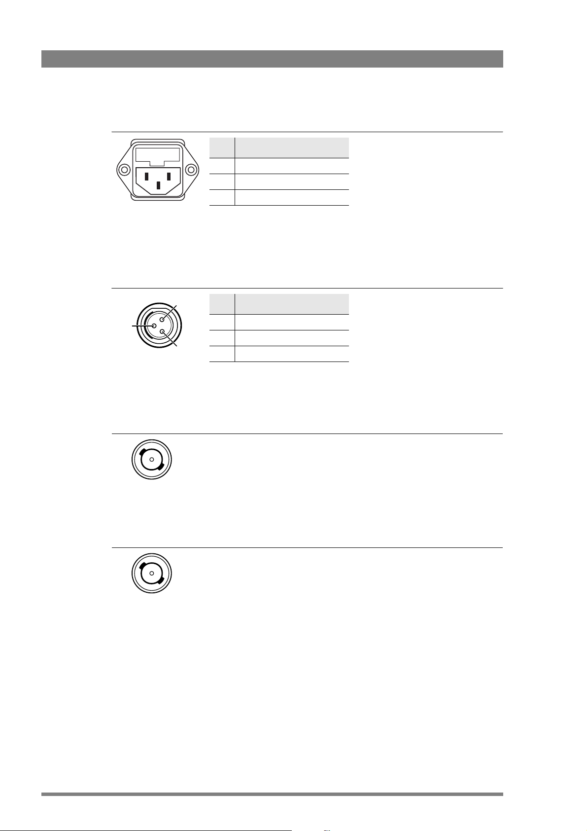
6.2.1 Mains power supply input socket
Pin Description
1
3
3-pin Euro
connector
2
1 Neutral
2Phase
3Earth
6.2.2 Script light connector
1
2
3
Fischer 3-pin female
connector
Pin Description
1 +12 VDC (max. 6 W)
2GND
3 Shield
6.2.3 Viewfinder component outputs (3x)
Mains input voltage: 100 to 240 VAC
(auto ranging)
Mains frequency: 50 to 60 Hz
Fuses (2): T4.0 A H250V
NOTE: the script light connector is
different than the one on the camera
adaptor!
Manufacturer/type: Fischer DBP 103
A052-28
BNC connector
6.2.4 External CVBS output
BNC connector
These 3 BNC sockets provide video output (component video) of the viewfinder
signal.
Y (1.0 Vpp with sync), Pr (0.7 Vpp), Pb (0.7 Vpp);
This BNC socket provides CVBS analog video output (1.0 Vpp)
The source for this output (EXT1 or EXT2) can be selected on the control panel
of the SuperXpander or in the camera (Xpander)
42 LDK 4488, LDK 4489 SuperXpander, Xpander User’s Guide (v5.0)
Page 43

6.2.5 Camera viewfinder connector
Chapter 6 - Connectors
19 16
18 1720
11
13 1215 14
8710 9 6
5
3241
20-pin female VF-
connector
Pin Description
1 -55 VDC
2 not connected
3GND
4INTN-D
5 VF Ext video
6 not connected
7 VF video return
8SDA-D
9SCL -D
10 VF Ext video return
Pin Description
11 GND
12 VF video
13 Pb VF return
14 Pr VF return
15 GND
16 + Batt
17 + Batt
18 Pb VF
19 +Pr VF
20 Shield
6.2.6 Top viewfinder connector (part of optional viewfinder support)
18
15 9
15-pin female D-sub
connector
Pin Description
1 VF video
2 VF Ext Video
3VF Pb
4GND
5 Shield
6+15 VDC
7SCL - D
8INTN-D
Pin Description
9 VF video return
10 VF Ext video return
11 +15 V D C
12 GND
13 Shield
14 VF Pr
15 SDA-D
LDK 4488, LDK 4489 SuperXpander, Xpander User’s Guide (v5.0) 43
Page 44

Chapter 6 - Connectors
44 LDK 4488, LDK 4489 SuperXpander, Xpander User’s Guide (v5.0)
Page 45

Chapter 7
Specifications
7. 1 Specifications for LDK 4488, LDK 4489
Item Val ue
Chapter 7 - Specifications
Power
Power requirements 100 to 240 VAC; 50 to 60 Hz 3 A; fuses (2x): T4.0 AH 250 V
Power consumption 250 VA max. fully equipped
Power connection IEC type 3-pin male
Environment
Operating temperatures 0°C to +45 °C (32 to +113 °F)
Storage temperatures -20 °C to +60 °C (-4 to +140 °F)
Weight (approx.) 14.4 kg (31.7 lbs) without viewfinder support
Dimensions (L x W x H) 526 x 286 x 385 mm (20.7 x 11.3 x 15.2 in) without viewfinder and
lens
Power outputs
Utility power output 1 (fixed) 15 VDC; XLR-4 female connector, P
Utility power output 2 (variable)
(SuperXpander only)
*) The maximum power consumption of the two utility outputs combined is 120 W
Script light output 12 VDC; P
Connections
Lens interface 36-pin Centronics female connector
External CVBS output 1.0 Vpp ~ 75 Ohm; BNC socket
External Components outputs Y (1.0 Vpp with sync.), Pr (0.7 Vpp), Pb (0.7 Vpp); 3x BNC sockets
VF connector (camera) 20-pin female VF connector
VF connector (top) 15-pin Sub-D connector, female
0 to 12 VDC; XLR-4 female connector, Pmax = 50 W
= 6 VA;
Fischer 3-pin female connector type DBP 103 A052-28
max
= 120 W *)
max
LDK 4488, LDK 4489 SuperXpander, Xpander User’s Guide (v5.0) 45
Page 46

Chapter 7 - Specifications
1
5V =
50W
5-1
2V =
50W
DC OUT
7. 2 Dimensions
Figure 7-1. Dimensions of the LDK 4488 SuperXpander with Triax transmission unit
342 43
385
115
32
285125.5 215
5V =
5-
2V =
DC OUT
50W
50W
286
109.5 416.5
526
22036 61
46 LDK 4488, LDK 4489 SuperXpander, Xpander User’s Guide (v5.0)
 Loading...