

Page 1
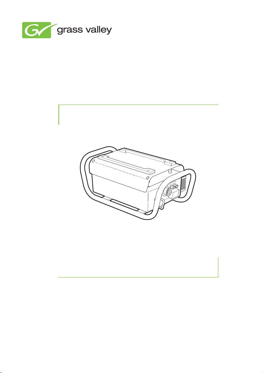
LDK 4426
User’s Guide
3922 496 31861 October 2011 v2.0
3G Camera Triax to 3G Fiber Converter
Page 2

Declaration of Conformity
We, Grass Valley Nederland B.V., Kapittelweg 10, 4827 HG Breda, The Netherlands,
declare under our sole responsibility that this product is in compliance with the
following standards:
- EN60065 : Safety
- EN55103-1:2009 EMC (Emission) for the following environments:
(E1) Residential;
(E2) Commercial and light industrial;
(E3) Urban outdoors;
(E4) Controlled EMC environment, and the rural outdoors environment.
- EN55103-2: EMC (Immunity)
following the provisions of:
- the EMC directive 2004/108/EC
- the Low Voltage directive 2006/95/EC
FCC Class A Statement
This product generates, uses, and can radiate radio frequency energy and if not
installed and used in accordance with the instructions, may cause interference to
radio communications.
It has been tested and found to comply with the limits for a class A digital device
pursuant to part 15 of the FCC rules, which are designed to provide reasonable
protection against such interference when operated in a commercial environment.
Operation of this product in a residential area is likely to cause interference in which
case the user at his own expense will be required to take whatever measures may
be required to correct the interference.
Copyright
Copyright Grass Valley Nederland B.V. 2011. Copying of this document and giving it
to others, and the use or communication of the contents thereof, are forbidden
without express authority. Offenders are liable to the payment of damages. All rights
are reserved in the event of the grant of a patent or the registration of a utility model
or design. Liable to technical alterations in the course of further development.
Trademarks
Grass Valley is a trademark of Grass Valley, Inc. All other tradenames referenced are
service marks, trademarks, or registered trademarks of their respective companies.
Page 3

Table of contents
Chapter 1 – Installation
1.1 Introduction . . . . . . . . . . . . . . . . . . . . . . . . . . . . . . . . . . . . . . 13
1.2 Configurations . . . . . . . . . . . . . . . . . . . . . . . . . . . . . . . . . . . . 13
1.2.1 3G Triax to dark fiber . . . . . . . . . . . . . . . . . . . . . . . . . . 13
1.2.2 3G Triax to hybrid fiber . . . . . . . . . . . . . . . . . . . . . . . . 14
1.2.3 3G Triax to hybrid fiber (with LDK 4410) . . . . . . . . . . . 15
1.3 Power . . . . . . . . . . . . . . . . . . . . . . . . . . . . . . . . . . . . . . . . . . . 16
1.4 Location of connectors and indicators . . . . . . . . . . . . . . . . 17
Chapter 2 – Operation
2.1 Indicator panel. . . . . . . . . . . . . . . . . . . . . . . . . . . . . . . . . . . . 19
2.2 Transmission . . . . . . . . . . . . . . . . . . . . . . . . . . . . . . . . . . . . . 20
2.2.1 Triax signal. . . . . . . . . . . . . . . . . . . . . . . . . . . . . . . . . . 20
2.2.2 Fiber connection . . . . . . . . . . . . . . . . . . . . . . . . . . . . . 21
2.3 Power and connection . . . . . . . . . . . . . . . . . . . . . . . . . . . . . 22
2.3.1 Local power indicator . . . . . . . . . . . . . . . . . . . . . . . . . 22
2.3.2 Camera test/camera connected indicators . . . . . . . . . 22
2.3.3 Base station power indicator . . . . . . . . . . . . . . . . . . . . 23
Chapter 3 – Specifications
3.1 Technical specifications . . . . . . . . . . . . . . . . . . . . . . . . . . . . 25
3.1.1 General . . . . . . . . . . . . . . . . . . . . . . . . . . . . . . . . . . . . 25
3.1.2 Dimensions . . . . . . . . . . . . . . . . . . . . . . . . . . . . . . . . . 26
3.2 Connectors. . . . . . . . . . . . . . . . . . . . . . . . . . . . . . . . . . . . . . . 26
3.2.1 Mains power connector. . . . . . . . . . . . . . . . . . . . . . . . 26
3.2.2 Triax connector . . . . . . . . . . . . . . . . . . . . . . . . . . . . . . 27
3.2.3 Fiber connector . . . . . . . . . . . . . . . . . . . . . . . . . . . . . . 27
LDK 4426 3G Camera Triax to 3G Fiber Converter User’s Guide (v2.0) 3
Page 4

End-of-life product recycling
Grass Valley’s innovation and excellence in product design also extends to the
programs we’ve established to manage the recycling of our products. Grass Valley
has developed a comprehensive end-of-life product take back program for recycle or
disposal of end-of-life products. Our program meets the requirements of the
European Union’s WEEE Directive and in the United States from the Environmental
Protection Agency, individual state or local agencies.
Grass Valley’s end-of-life product take back program assures proper disposal by use
of Best Available Technology. This program accepts any Grass Valley branded
equipment. Upon request, a Certificate of Recycling or a Certificate of Destruction,
depending on the ultimate disposition of the product, can be sent to the requester.
Grass Valley will be responsible for all costs associated with recycling and disposal,
including freight, however you are responsible for the removal of the equipment
from your facility and packing the equipment ready for pickup.
For further information on the Grass Valley product take back system please contact
Grass Valley at + 800 80 80 20 20 or +33 1 48 25 20 20 from most other countries.
In the US and Canada please call 800-547-8949 or 530-478-4148. Ask to be
connected to the EH&S Department. In addition, information concerning Grass
Valley’s environmental policy can be found at:
www.grassvalley.com/about/environmental-policy
4 LDK 4426 3G Camera Triax to 3G Fiber Converter User’s Guide (v2.0)
Page 5

Packing/Unpacking
Inspect the shipping container for evidence of damage immediately after receipt. If
the shipping container or cushioning material is damaged, it should be kept until the
contents of the shipment have been checked for completeness and the unit has
been checked mechanically and electrically.
The shipping container should be placed upright and opened from the top. Remove
the cushioning material and lift out the contents.
The contents of the shipment should be checked against the packing list. If the
contents are incomplete, if there is mechanical damage or defect, or if the unit does
not perform correctly when unpacked, notify your Grass Valley sales or service
centre within eight days.
If the shipping container shows signs of damage or stress, notify the carrier as well.
If the unit is being returned to Grass Valley for servicing, try to use the containers
and materials of the original packaging. Attach a tag indicating the type of service
required, return address, model number, full serial number and the return number
which will be supplied by your Grass Valley service centre.
If the original packing can no longer be used, the following general instructions
should be used for repacking with commercially available materials:
• Wrap unit in heavy paper or plastic.
• Use a strong shipping container.
• Use a layer of shock-absorbing material around all sides of the unit to provide
firm cushioning and prevent movement inside container.
• Seal shipping container securely.
• Mark shipping container FRAGILE to ensure careful handling.
LDK 4426 3G Camera Triax to 3G Fiber Converter User’s Guide (v2.0) 5
Page 6
Important information
Read this information carefully before installing this equipment and retain them for
future reference. Read and comply with the warning and caution notices that appear
in the manual. Any changes or modifications not expressly approved in this manual
could void your authority to operate this equipment.
Safety Summary
This information is intended as a guide for trained and qualified personnel who are
aware of the dangers involved in handling potentially hazardous electrical/electronic
equipment. It is not intended to contain a complete list of all safety precautions
which should be observed by personnel in using this or other electronic equipment.
The installation of this equipment involves risks both to personnel and equipment
and must be performed only by qualified personnel exercising due care.
During installation and operation of this equipment, local building safety and fire
protection standards must be observed.
Whenever it is likely that safe operation is impaired, the apparatus must be made
inoperative and secured against any unintended operation. The appropriate servicing
authority must then be informed. For example, safety is likely to be impaired if the
apparatus fails to perform the intended function or shows visible damage.
Read and comply with the warning and caution notices that appear in the manual.
This symbol is intended to alert the user to the presence of uninsulated "dangerous
voltage" source within the unit's enclosure that may be of sufficient magnitude to
constitute a risk of electric shock to persons. Accordingly it is dangerous to touch
any parts within this unit.
Warnings
Warnings indicate danger that requires correct procedures or practices to prevent
death or injury to personnel.
Do not modify this equipment;
• Do not use any accessories other than those recommended by the
manufacturer;
• In case of an emergency ensure that the power is disconnected;
• Mount equipment so that power lead can be accessed to disconnect power;
• There are no user serviceable parts inside. Refer servicing to qualified
personnel only or contact your local Grass Valley representative;
6 LDK 4426 3G Camera Triax to 3G Fiber Converter User’s Guide (v2.0)
Page 7

Cautions
• Observe local building safety, fire protection and electrical installation
standards during installation and operation of this equipment;
• Whenever it is likely that safe operation is impaired, the apparatus must be
made inoperative and secured against any unintended operation.
• Always power the unit from the building’s installation (overvoltage CAT. II). The
unit is not designed to be powered directly from a mains distribution net.
Cautions indicate procedures or practices that should be followed to prevent
damage or destruction to equipment or property.
• Do not subject the unit to severe shocks or vibration;
• Do not expose the unit to extremes of temperature;
• To prevent risk of overheating, ventilate the product correctly: do not cover the
unit with a rain cover as this may obstruct proper ventilation of the unit.
LDK 4426 3G Camera Triax to 3G Fiber Converter User’s Guide (v2.0) 7
Page 8

Dust and water protection
The unit is protected according to IEC 60529 IP54 (dust-protected and resistant to
splashing water) and it is tested for outdoor use. This means that splashing against
the enclosure from any direction shall have no harmful effect.
However, to prevent damage or injury take the following precautions:
• To prevent rain from entering the mains entty, only use the unit in its default,
horizontal position.
• Always unplug the mains plug before a wet or moist plug is disconnected from
the unit.
• When not in use, always protect connectors with their dust/protection caps.
8 LDK 4426 3G Camera Triax to 3G Fiber Converter User’s Guide (v2.0)
Page 9

Fiber-optic transmission units
CLASS 1
LASER PRODUCT
LASER KLASSE 1
PRODUKT
Laser safety statement (Europe)
Fiber-optic transmission units are classified as a “CLASS 1 Laser Product” according
to EN 60825-1, Safety of Laser products. Class 1 laser products are considered safe
and do not result in biological hazard if used according to the instructions.
Laser safety statement (US)
Fiber-optic transmission units are classified as a “CLASS 1 Laser Product” according
to 21CFR 1040.10 of the US Food and Drug Administration (FDA) Center for Devices
and Radiological Health.
Use of controls, adjustments or performance of procedures other than those
specified herein may result in hazardous radiation exposure.
To ensure proper use of this product, please read this instruction manual carefully
and retain for future reference. Should the unit ever require maintenance, contact an
authorized service location.
Fiber-optic cable precautions
Fiber-optic cables and connectors are easily damaged; take the following
percautions into account:
– Do not bend the cable beyond the minimum permissible bend range
specified for the cable.
– Avoid kinks in the cable.
– Avoid subjecting the cable to a high tension force (even momentarily).
– Do not twist the cable when connecting it to equipment.
– Insert connectors straight and fully into their corresponding sockets.
– In fiber-optic cable systems always put the dust caps on cable and panel
connectors immediately after disconnecting a cable. Keep the dust caps
clean.
LDK 4426 3G Camera Triax to 3G Fiber Converter User’s Guide (v2.0) 9
Page 10

Cleaning fiber-optic connectors
Warning
Never clean an optical connector attached to a fiber that is carrying light.
Particles of foreign matter on the tip of a ferrule can have a disabling effect on fiberoptic transmission. Fiber-optic connectors need to be cleaned every time they are
mated and unmated; it is essential that fiber-optic users develop the necessary
discipline to always clean the connectors before they are mated.
Use a commerially available cleaning kit specifically designed for fiber-optic
connectors and follow the manufacturer's instructions carefully.
• The connector sections to be cleaned include the tips and sides of ferrules, the
interior walls of alignment sleeves, and the interior and exterior of connector
shells.
• For plugs, the interior surfaces of alignment sleeves and the tips of ferrules are
to be cleaned with a cleaning stick treated with the appropriate fluid. (Cleaning
sticks with a slender design are available that allow alignment sleeves to be
cleaned without having to detach them.)
• For jacks, it is important to clean both the tips and sides of the completely
protruding ferrules.
• Both the male and female connector shells tend to attract dust and metal
particles, so it is important to clean both the insides and outsides.
• The fiber end face and ferrule must be absolutely clean before it is inserted
into a transmitter or receiver.
• Mate the connector immediately! Don't let the connector lie around and
collect dust before mating.
• Air can be used to remove lint or loose dust from the port of a transmitter or
receiver to be mated with the connector. Never insert any liquid into the ports.
10 LDK 4426 3G Camera Triax to 3G Fiber Converter User’s Guide (v2.0)
Page 11

Earthing
This unit has a protective earth terminal (M5-screw) This terminal is internally
connected to the protective earth conductor of the power cable.
The unit must be connect to earth either by using a earthed mains power cable OR
by connecting a separate earth cable between the protective earth terminal and the
building’s central earth.
Mains lead wiring for UK users
The wires in the mains lead are colored in accordance with the following code:
GREEN and YELLOW - EARTH,
BLUE - NEUTRAL,
BROWN - LIVE
As the colors of the wires in the mains lead of this apparatus may not correspond
with the colored markings identifying the terminals in your plug proceed as follows:
• The wire colored GREEN and YELLOW must be connected to the terminal on
the plug marked with the letter E or by the safety earth symbol or colored
GREEN or GREEN and YELLOW.
• The wire colored BROWN must be connected to the terminal marked with the
letter L or colored RED.
• The wire colored BLUE must be connected to the terminal marked with the
letter N or colored BLACK.
Ensure that your equipment is connected correctly - if you are in any doubt consult a
qualified electrician.
LDK 4426 3G Camera Triax to 3G Fiber Converter User’s Guide (v2.0) 11
Page 12

12 LDK 4426 3G Camera Triax to 3G Fiber Converter User’s Guide (v2.0)
Page 13

Chapter 1
Local power
LDK 4420
3G Twin Base
Station
Studio camera
with LDK 5418
3G Triax adapter
LDK 4426 3G
Camera Triax to
Fiber Converter
Dark fiberTr ia x
Installation
1.1 Introduction
The 3G Camera Triax to 3G Fiber Converter is used to convert 3G Triax signals
coming from a camera with an LDK 5418 3G Triax adapter to dark fiber or hybrid
fiber signals that are routed to the LDK 4420 3G Twin Base Station. The hybrid fiber
version of the unit can also connect to an LDK 4410 3G Fiber Base Station.
1.2 Configurations
1.2 .1 3G Triax to dark fiber
A studio camera with a 3G Triax adapter is connected to the converter with a Triax
cable.
Chapter 1 - Installation
LDK 4426 3G Camera Triax to 3G Fiber Converter User’s Guide (v2.0) 13
Page 14

Chapter 1 - Installation
Local power
LDK 4420
3G Twin Base
Station
Studio camera
with LDK 5418
3G Triax adapter
LDK 4426 3G
Camera Triax to
Fiber Converter
Hybrid
fiber
LDK 4429 3G
Twi n Powe r
Converter
Tr ia x
The following versions of the 3G Camera Triax to 3G Fiber Converter are available:
Product
version
LDK 4426/01 Fisher 2x SC (mono fiber)
LDK 4426/06 ARD 2x SC (mono fiber)
LDK 4426/11 Lemo-4E 2x SC (mono fiber)
LDK 4426/16 Lemo-3T 2x SC (mono fiber)
LDK 4426/41 BBC Lemo 2x SC (mono fiber)
LDK 4426/51 Trilock 2x SC (mono fiber)
LDK 4426/02 Fisher 2x ST (mono fiber)
LDK 4426/07 ARD 2x ST (mono fiber)
LDK 4426/12 Lemo-4E 2x ST (mono fiber)
LDK 4426/17 Lemo-3T 2x ST (mono fiber)
LDK 4426/42 BBC Lemo 2x ST (mono fiber)
LDK 4426/52 Trilock 2x ST (mono fiber)
Triax connector
(from camera)
1.2 .2 3G Triax to hybrid fiber
Fiber connectors
(to base station)
14 LDK 4426 3G Camera Triax to 3G Fiber Converter User’s Guide (v2.0)
Page 15

Chapter 1 - Installation
Note
Local power
LDK 4410
3G Fiber Base
Station
Studio camera
with LDK 5418
3G Triax adapter
LDK 4426 3G
Camera Triax to
Fiber Converter
Hybrid fiberTr ia x
The following versions of the 3G Camera Triax to 3G Fiber Converter are available:
Product
version
LDK 4426/00 Fisher Lemo (hybrid fiber)
LDK 4426/05 ARD Lemo (hybrid fiber)
LDK 4426/10 Lemo-4E Lemo (hybrid fiber)
LDK 4426/15 Lemo-3T Lemo (hybrid fiber)
LDK 4426/40 BBC Lemo Lemo (hybrid fiber)
LDK 4426/50 Trilock Lemo (hybrid fiber)
Triax connector
(from camera)
Fiber connector
(to base station)
1.2 .3 3G Triax to hybrid fiber (with LDK 4410)
Transmission diagnostics are not fully supported with this configuration.
The converter can also be used to connect a 3G Triax equipped camera to an
LDK 4410 3G Fiber Base station using a hybrid fiber connection. Power can be
applied locally to the converter or via the hybrid fiber cable by the Base Station.
LDK 4426 3G Camera Triax to 3G Fiber Converter User’s Guide (v2.0) 15
Page 16

1.3 Power
Note
By default the camera and the 3G Camera Triax to 3G Fiber Converter are powered
by the base station.
When a hybrid fiber connector is used, the unit can be powered via the hybrid cable
(by the base station) or via local mains power. Switching between both power
situations is done automatically and occurs only once, at startup. The automatic
switch chooses the first power available and blocks further switching.
Applying local power will not force switching power when the camera is already
powered.
The unit can be forced to use local power as follows:
1. Remove the hybrid fiber connector;
2. Apply power to the mains entry. The system starts up using local power;
3. Reconnect the hybrid fiber connector.
Mains cable guiding
When connecting a mains cable, make sure to guide the cable through the hinge on
the metal outer frame of the unit as indicated below:
Chapter 1 - Installation
16 LDK 4426 3G Camera Triax to 3G Fiber Converter User’s Guide (v2.0)
Page 17

Chapter 1 - Installation
Tr ia x
connector
Indicator
panel
Mains
connector
Fiber
connector(s) *)
Earth
pin
*) Can be either two mono (dark) fiber connectors or a single hybrid fiber
connector.
1.4 Location of connectors and indicators
LDK 4426 3G Camera Triax to 3G Fiber Converter User’s Guide (v2.0) 17
Page 18

Chapter 1 - Installation
18 LDK 4426 3G Camera Triax to 3G Fiber Converter User’s Guide (v2.0)
Page 19

Chapter 2
Local Power
indicator
Camera Test
indicator
Base station
power indicator
Camera
connected
indicator
Triax signal
status indicator
Fiber signal
status indicator
Triax cable
quality bar
Fiber cable
quality bar
Operation
2.1 Indicator panel
During operation the indicator panel gives an overview of power and transmission
parameters:
LOC
PWR
CAM
TST
CAM
CON
Chapter 2 - Operation
LDK 4426 3G Camera Triax to 3G Fiber Converter User’s Guide (v2.0) 19
STATUS
BS
PWR
Page 20

2.2 Transmis s i on
STATUS
BS
PWR
LOC
PWR
CAM
TST
CAM
CON
Good (< 100%) Poor (> 135%)
Triax signal status (camera > convertor):
Yellow: critical, check cabling
Red: error, check cabling
Red (flashing): no signal received
- No camera connected, or:
- Power switched off
Triax signal quality (camera > convertor):
Green: ok, normal operation
2.2.1 Triax signal
At the left side of the control panel, a vertical bar of six green lights show the cable
quality of the Triax connection between the camera and the convertor unit. More
lights mean better quality. When all six indicators are lit, transmission is optimal.
The values in the table below indicate the percentage of the nominal (100%) cable
length in use.
The indicator at the bottom provides signal status information about the Triax
connection between the convertor unit and the camera.
Chapter 2 - Operation
20 LDK 4426 3G Camera Triax to 3G Fiber Converter User’s Guide (v2.0)
Page 21

2.2.2 Fiber connection
Good (> 6 dBm) Poor (< 0 dBm)
Fiber (B) signal status (BS > convertor):
Yellow: critical, check cabling
Red: error, check cabling
Red (flashing):no signal received
- Fiber cable not connected, or:
- Base Station power switched off
Fiber (B) signal status (BS > convertor):
Green: ok, normal operation
At the right side of the control panel, a vertical bar of six green lights show the cable
quality of the Fiber connection between the Base Station and the convertor unit.
More lights mean better quality. When all six indicators are lit, transmission is
optimal.
The values in the table below indicate the optical margin (budget) left.
The indicator at the bottom provides signal status information about the Fiber
connection between the Base Station and the convertor.
LOC
PWR
CAM
TST
CAM
CON
Chapter 2 - Operation
BS
STATUS
PWR
LDK 4426 3G Camera Triax to 3G Fiber Converter User’s Guide (v2.0) 21
Page 22

2.3 Power and connection
LOC
PWR
CAM
TST
CAM
CON
LOC
PWR
CAM
TST
CAM
CON
CAM
TST
LOC
PWR
CAM
CON
LOC
PWR
CAM
TST
CAM
CON
LOC
PWR
CAM
TST
CAM
CON
LOC
PWR
CAM
TST
CAM
CON
LOC
PWR
CAM
TST
CAM
CON
LOC
PWR
CAM
TST
CAM
CON
2.3.1 Local power indicator
This green indicator lights when local power is used.
Indicators Condition Indicators Condition
Chapter 2 - Operation
LOC PWR green:
Local power (mains) is
used.
LOC PWR off:
Local power (mains) is not
used.
2.3.2 Camera test/camera connected indicators
These indicators provide information about the power status of the connection:
Indicators Condition Indicators Condition
CAM CON green flashing:
Transmission cable is
connected to camera.
CAM CON green:
Transmission cable is
connected to camera and
camera is powered.
CAM TST red flashing:
Transmission cable open.
CAM TST red:
Transmission cable error:
shortcircuit or wrong
power system.
CAM TST yellow:
Camera power is
switched off by a control
panel or from a menu.
CAM TST orange:
Selftests are running
22 LDK 4426 3G Camera Triax to 3G Fiber Converter User’s Guide (v2.0)
Page 23

2.3.3 Base station power indicator
BS
PWRBSPWR
This green indicator lights when base station power is used to power the camera.
Indicators Condition Indicators Condition
Chapter 2 - Operation
BS PWR green:
Base Station power is in
use.
BS PWR off:
Base Station power is in
not in use.
LDK 4426 3G Camera Triax to 3G Fiber Converter User’s Guide (v2.0) 23
Page 24

Chapter 2 - Operation
24 LDK 4426 3G Camera Triax to 3G Fiber Converter User’s Guide (v2.0)
Page 25

Chapter 3
Specifications
3.1 Technical specifications
3.1.1 General
Dimensions (W x H x L) 250 x 194 x 480 mm (9.8 x 7.6 x 18.9 in)
Weight (approx.) 10.7 kg (23.6 lbs)
Operating temperatures -20 to +45 °C (-4 to +113 °F)
Storage temperatures -25 to +60 °C (-13 to +140 °F)
Power requirements 100 to 240 VAC, 47 to 63 Hz
Power consumption (max.) 420 W
Power connection IEC type, 3-pin male
Triax connector Depending on product version
Triax cable length 1,200 m (3,900 ft) using 14 mm (0.55 in) Triax cable
Fiber connector Depending on product version
Fiber cable length Depending on connectors and optical budget
Chapter 3 - Specifications
LDK 4426 3G Camera Triax to 3G Fiber Converter User’s Guide (v2.0) 25
Page 26

3.1.2 Dimensions
480 mm
250 mm
194 mm
Fuses (2x): 8AT / 250 VAC
Pin Description
1 Neutral
2Line
3Earth
IEC style 3-pin male
Chapter 3 - Specifications
3.2 Connectors
3.2.1 Mains power connector
26 LDK 4426 3G Camera Triax to 3G Fiber Converter User’s Guide (v2.0)
1
2
3
Page 27

3.2.2 Triax connector
Pin Description
1 Inner pin: signal + power
2 Inner shield: Return
3 Outer shield: Housing
Various types available
Lemo hybrid fiber connector compliant
with SMPTE 304M.
Pin Description
1 Optic fiber channel A
2 Power supply return
3 Optic fiber channel B
4 Power supply
1
4
2
3
Various types available
Cn Description
A Optic fiber A
B Optic fiber B
Various types available
3
2
1
3.2.3 Fiber connector
Hybrid fiber connector
Chapter 3 - Specifications
Dark fiber connectors
A B
LDK 4426 3G Camera Triax to 3G Fiber Converter User’s Guide (v2.0) 27
Page 28

Chapter 3 - Specifications
28 LDK 4426 3G Camera Triax to 3G Fiber Converter User’s Guide (v2.0)
Page 29

LDK 4426 3G Camera Triax to 3G Fiber Converter User’s Guide (v2.0) 29
Page 30

Printed in The Netherlands Copyright Grass Valley Nederland B.V. 2011
 Loading...