

Page 1
3922 496 30481 February 2007 v4.0
LDK 5417 + LDK 4417
User’s Guide
SD Digital Triax camera system
Page 2

Declaration of Conformity
We, Grass Valley Nederland B.V., Kapittelweg 10, 4827 HG Breda, The
Netherlands, declare under our sole responsibility that this product is in
compliance with the following standards:
- EN60065 : Safety
- EN55103-1: EMC (Emission)
- EN55103-2: EMC (Immunity)
following the provisions of:
a. the Low Voltage directive 2006/95/EC
b. the EMC directive 2004/108/EC
FCC Class A Statement
This product generates, uses, and can radiate radio frequency energy and if
not installed and used in accordance with the instructions, may cause
interference to radio communications.
It has been tested and found to comply with the limits for a class A digital
device pursuant to part 15 of the FCC rules, which are designed to provide
reasonable protection against such interference when operated in a
commercial environment.
Operation of this product in a residential area is likely to cause interference in
which case the user at his own expense will be required to take whatever
measures may be required to correct the interference.
Copyright
Copyright Grass Valley Nederland B.V. 2007. Copying of this document and
giving it to others, and the use or communication of the contents thereof, are
forbidden without express authority. Offenders are liable to the payment of
damages. All rights are reserved in the event of the grant of a patent or the
registration of a utility model or design. Liable to technical alterations in the
course of further development.
Trademarks
Grass Valley and Infinity are trademarks of Grass Valley, Inc. All other
tradenames referenced are service marks, trademarks, or registered
trademarks of their respective companies.
Website
Visit the Grass Valley public website to download the latest user’s guide
updates and additional information about your broadcast product:
www.grassvalley.com
Page 3

LDK 5417 + LDK 4417 User’s Guide i
Table of contents
1 – Specifications
1.1 LDK 5417 Digital Triax Adapter . . . . . . . . . . . . . . . . . . . . . . . . . . . . . . . . . . . . . . . . . .1
1.2 LDK 4417 Digital Triax Base Station. . . . . . . . . . . . . . . . . . . . . . . . . . . . . . . . . . . . . . . 1
1.3 Triax cable specifications . . . . . . . . . . . . . . . . . . . . . . . . . . . . . . . . . . . . . . . . . . . . . . . 2
1.4 Remote control cables. . . . . . . . . . . . . . . . . . . . . . . . . . . . . . . . . . . . . . . . . . . . . . . . . . 2
2 – Configuration
2.1 Typical setup . . . . . . . . . . . . . . . . . . . . . . . . . . . . . . . . . . . . . . . . . . . . . . . . . . . . . . . . . 4
2.2 Connecting a control panel. . . . . . . . . . . . . . . . . . . . . . . . . . . . . . . . . . . . . . . . . . . . . . 5
3 – Adapter controls
3.1 Powering the camera . . . . . . . . . . . . . . . . . . . . . . . . . . . . . . . . . . . . . . . . . . . . . . . . . .6
3.2 Selecting monitoring signals . . . . . . . . . . . . . . . . . . . . . . . . . . . . . . . . . . . . . . . . . . . . 7
3.3 Audio . . . . . . . . . . . . . . . . . . . . . . . . . . . . . . . . . . . . . . . . . . . . . . . . . . . . . . . . . . . . . . .8
3.4 Intercom . . . . . . . . . . . . . . . . . . . . . . . . . . . . . . . . . . . . . . . . . . . . . . . . . . . . . . . . . . . . .8
3.5 Communication . . . . . . . . . . . . . . . . . . . . . . . . . . . . . . . . . . . . . . . . . . . . . . . . . . . . . . .9
4 – Adapter connectors
4.1 Triax connector . . . . . . . . . . . . . . . . . . . . . . . . . . . . . . . . . . . . . . . . . . . . . . . . . . . . . . 10
4.2 Ext1/Ext2 video output connector . . . . . . . . . . . . . . . . . . . . . . . . . . . . . . . . . . . . . . .10
4.3 Viewfinder / External 1 video output connector . . . . . . . . . . . . . . . . . . . . . . . . . . . . 10
4.4 Script light power supply socket . . . . . . . . . . . . . . . . . . . . . . . . . . . . . . . . . . . . . . . . 11
4.5 DC power output socket . . . . . . . . . . . . . . . . . . . . . . . . . . . . . . . . . . . . . . . . . . . . . . . 11
4.6 Audio microphone 1 connector . . . . . . . . . . . . . . . . . . . . . . . . . . . . . . . . . . . . . . . . . 11
4.7 Intercom headset connector . . . . . . . . . . . . . . . . . . . . . . . . . . . . . . . . . . . . . . . . . . . . 12
5 – Camera install menu
6 – Base Station
6.1 Dimensions, weight. . . . . . . . . . . . . . . . . . . . . . . . . . . . . . . . . . . . . . . . . . . . . . . . . . . 13
6.2 Installation of Base Station in rack. . . . . . . . . . . . . . . . . . . . . . . . . . . . . . . . . . . . . . . 14
7 – Mains power supply
7.1 Adapting the Base Station to the mains voltage. . . . . . . . . . . . . . . . . . . . . . . . . . . . 19
7.2 Fuse changing . . . . . . . . . . . . . . . . . . . . . . . . . . . . . . . . . . . . . . . . . . . . . . . . . . . . . . . 19
8 – Base Station connections
8.1 Back panel . . . . . . . . . . . . . . . . . . . . . . . . . . . . . . . . . . . . . . . . . . . . . . . . . . . . . . . . . .20
Page 4

LDK 5417 + LDK 4417 User’s Guide ii
9 – Base Station controls
9.1 Front panel . . . . . . . . . . . . . . . . . . . . . . . . . . . . . . . . . . . . . . . . . . . . . . . . . . . . . . . . . .25
10 – Base Station installation
10.1 Audio. . . . . . . . . . . . . . . . . . . . . . . . . . . . . . . . . . . . . . . . . . . . . . . . . . . . . . . . . . . . . . .27
10.2 Intercom . . . . . . . . . . . . . . . . . . . . . . . . . . . . . . . . . . . . . . . . . . . . . . . . . . . . . . . . . . . .27
10.3 Video . . . . . . . . . . . . . . . . . . . . . . . . . . . . . . . . . . . . . . . . . . . . . . . . . . . . . . . . . . . . . . .28
10.4 Adaptation of BS to external on-air signal controls from the studio . . . . . . . . . . .32
11 – DC/DC converters
11.1 Installation . . . . . . . . . . . . . . . . . . . . . . . . . . . . . . . . . . . . . . . . . . . . . . . . . . . . . . . . . .36
Page 5

LDK 5417 + LDK 4417 User’s Guide iii
End-of-life product recycling
Grass Valley’s innovation and excellence in product design also extends to the programs we’ve
established to manage the recycling of our products. Grass Valley has developed a
comprehensive end-of-life product take back program for recycle or disposal of end-of-life
products. Our program meets the requirements of the European Union’s WEEE Directive and
in the United States from the Environmental Protection Agency, individual state or local
agencies.
Grass Valley’s end-of-life product take back program assures proper disposal by use of Best
Available Technology. This program accepts any Grass Valley branded equipment. Upon
request, a Certificate of Recycling or a Certificate of Destruction, depending on the ultimate
disposition of the product, can be sent to the requester.
Grass Valley will be responsible for all costs associated with recycling and disposal, including
freight, however you are responsible for the removal of the equipment from your facility and
packing the equipment ready for pickup.
For further information on the Grass Valley product take back system please contact Grass
Valley at + 800 80 80 20 20 or +33 1 48 25 20 20 from most other countries. In the US and
Canada please call 800-547-8949 or 530-478-4148. Ask to be connected to the EH&S
Department. In addition, information concerning the program can be found at:
www.grassvalley.com/environment
Page 6

LDK 5417 + LDK 4417 User’s Guide iv
Important information
Read this information carefully before installing this equipment and retain them for future
reference. Read and comply with the warning and caution notices that appear in the manual.
Any changes or modifications not expressly approved in this manual could void your authority
to operate this equipment.
Safety Summary
This informaton is intended as a guide for trained and qualified personnel who are aware of the
dangers involved in handling potentially hazardous electrical/electronic equipment. It is not
intended to contain a complete list of all safety precautions which should be observed by
personnel in using this or other electronic equipment.
The installation of this equipment involves risks both to personnel and equipment and must be
performed only by qualified personnel exercising due care.
During installation and operation of this equipment, local building safety and fire protection
standards must be observed.
Before connecting the equipment to the power supply of the installation, the proper
functioning of the protective earth lead of the installation needs to be verified.
Whenever it is likely that safe operation is impaired, the apparatus must be made inoperative
and secured against any unintended operation. The appropriate servicing authority must then
be informed. For example, safety is likely to be impaired if the apparatus fails to perform the
intended function or shows visible damage.
Warnings
Warnings indicate danger that requires correct procedures or practices to prevent death or
injury to personnel.
• Do not modify this equipment;
• Installation of this equipment must only be performed by qualified personnel;
• Only mount the unit on a tripod or pedestal and head that can carry a payload of more than
50 kg.
• Do not use any accessories other than those recommended by the manufacturer;
• In case of an emergency ensure that the power is disconnected;
• Mount equipment so that power lead can be accessed to disconnect power;
• Any interruption of the protection conductor inside or outside the apparatus, or
disconnection of the protective earth terminal, is likely to make the apparatus dangerous.
Intentional interruption is prohibited;
• Use only fuses of the type and rating specified;
• To prevent fire or shock hazard, do not expose the unit to rain. If the unit is used in a wet
environment, a rain cover should be used for personal safety reasons;
• There are no user servicable parts inside. Refer servicing to qualified personnel only or
contact your local Grass Valley representative;
• Observe local building safety, fire protection and electrical installation standards during
installation and operation of this equipment;
Page 7

LDK 5417 + LDK 4417 User’s Guide v
• Before connecting the equipment to the power supply of the installation, verify the proper
functioning of the protective earth lead;
• Whenever it is likely that safe operation is impaired, the apparatus must be made
inoperative and secured against any unintended operation.
Cautions
Cautions indicate procedures or practices that should be followed to prevent damage or
destruction to equipment or property.
• Do not subject the unit to severe shocks or vibration;
• Do not expose the unit to extremes of temperature;
• To prevent risk of overheating, ventilate the product correctly;
• Connect the product only to a power source with the specified voltage rating.
Page 8

LDK 5417 + LDK 4417 User’s Guide vi
Wichtige Hinweise
Lesen Sie bitte diese Hinweise genau bevor Sie diese Apparatur installieren und erhalten Sie
Sie für künftiges Nachslagen. Beachten und Lesen Sie alle mit “Achtung” und “Vorsicht”
gekennzeichneten Warnhinweise.
Änderungen haben zur Folge, dass die Garantie ungültig wird und der Benutzer für etwaige
durch die veränderte Ausrüstung verursachte Störungen haftbar gemacht werden könnte.
Sicherheit (Zusammenfassung)
Diese Informationen sind als Leitfaden für qualifiziertes Fachpersonal gedacht, das die
Gefahren beim Umgang mit potenziell gefährlicher elektrischer/elektronischer Ausrüstung
kennt. Es handelt sich dabei nicht um eine vollständige Zusammenstellung aller
Sicherheitsvorkehrungen, die beim Gebrauch dieser oder anderer elektronischer Geräte zu
beachten sind.
Die Montage, Wartung und Instandsetzung dieser Ausrüstung ist mit Risiken für Personal und
Ausrüstung verbunden und darf nur von qualifiziertem Personal vorgenommen werden, wobei
mit der nötigen Sorgfalt vorzugehen ist.
Beim Einbau und Betrieb dieser Ausrüstung müssen die örtlichen Gebäudesicherheits- und
Brandschutzvorschriften beachtet werden. Vor dem Anschluss der Ausrüstung an die
Stromversorgung der Anlage muss überprüft werden, ob der Schutzleiter intakt ist.
Wenn eine Beeinträchtigung des sicheren Betriebs wahrscheinlich ist, muss das Gerät außer
Betrieb gesetzt und gegen ungewollten Betrieb gesichert werden. Dann muss der zuständige
Kundendienst benachrichtigt werden. Eine Beeinträchtigung der Sicherheit ist zum Beispiel
dann wahrscheinlich, wenn das Gerät nicht wie vorgesehen funktioniert oder einen sichtbaren
Schaden aufweist.
Vorsicht
Mit “Vorsicht” wird auf eine Gefahr hingewiesen, die korrekte Arbeits- oder Verfahrensweisen
erfordert, um Tod oder Verletzung zu verhindern.
• An dieser Ausrüstung dürfen keine Änderungen vorgenommen werden;
• Die Montage dieser Ausrüstung darf nur von Fachpersonal vorgenommen werden;
• Diese Ausrüstung soll nur auf einem Stativ oder Sokkel und einem Kopf aufgestellt
werden die eine Last von mehr als 50 kg trägen kann.
• Es sollen nur von den Hersteller empfohlene Zubehöre verwendet werden;
• Bei Eintreten eines Notfalls unbedingt die Stromzufuhr abschalten;
• Ausrüstung so montieren, daß das Netzkabel zum Abschalten der Stromzufuhr zugänglich
ist;
• Jede Unterbrechung des Schutzleiters innerhalb oder ausserhalb des Geräts oder
Trennung der Schutzleiter-anschlussklemme Könnte das Gerät fefährlich machen. Eine
absichtliche Unterbrechung ist untersagt;
• Es dürfen nur Sicherungen des vorgeschriebenen Typs und Nennwerts verwendet
werden;
• Um Feuer oder Schlaggefahr vorzubeugen, soll das Produkt nie an Regen ausgesetzt
werden. Wenn das Produkt in eine nasse Umgebung verwendet wird muss eind
Regenüberzug verwendet werden.
Page 9

LDK 5417 + LDK 4417 User’s Guide vii
• Dieses Produkt enthält keine Anwenderteile. Reparatur und Wartung nur von
qualifiziertem Fachpersonal vornehmen lassen oder nehmen Sie Kontakt auf mit Ihrem
Grass Valley Vertretene;
• Beim Einbau und Betrieb dieser Ausrüstung müssen die örtlichen Gebäudesicherheitsund Brandschutzvorschriften beachtet werden;
• Vor dem Anschluss der Ausrüstung an die Stromversorgung der Anlage muss überprüft
werden, ob der Schutzleiter intakt ist;
• Wenn eine Beeinträchtigung des sicheren Betriebs wahrscheinlich ist, muss das Gerät
außer Betrieb gesetzt und gegen ungewollten Betrieb gesichert werden.
Achtung
Mit “Achtung” werden Arbeitsanweisungen gekennzeichnet, die zu befolgen sind, um eine
Beschädigung oder Zerstörung der Ausrüstung bzw. von Eigentum zu verhindern.
• Dieses Produkt darf nicht an extremen stöße oder Zittern ausgesetzt werden;
• Dieses Produkt darf nicht an extremen Temperaturen ausgesetzt werden;
• Um einer Überhitzungsgefahr vorzubeugen, ist das Produkt korrekt zu belüften;
• Das Produkt darf nur an eine Stromquelle mit der vorgeschriebenen Nennspannung
angeschlossen werden.
Page 10

LDK 5417 + LDK 4417 User’s Guide viii
Installation notices
For proper installation the following NEC articles should be noticed:
Regarding communication circuits:
– Installation of equipment (NEC article 800.18).
Regarding radio and television equipment:
– Avoid contact with conductors of other systems (NEC article 810.13);
Provide extensive, separate clearance requirements for indoor and outdoor locations (NEC
article 810.18).
Mains power supply chord
General
A mains power supply chord is not shipped with the device. To connect the device to the mains
the following power supply cord is advised: type H03 VV-F or H03 VVH2-F flexible wire: 1 mm²,
250V / 10A minimum or 16 AWG.
When the device is installed in one of the following countries the power chord must be
compliant to the indicated specifications and regulations below:
Denmark
Supply cord of single-phase equipment having a rated current not exceeding 10A shall be
provided with a plug according to the Heavy Current Regulations section 107-2-D1. Class I
equipment provided with socket-outlets with earth contact or which are intended to be used in
locations where protection against indirect contact is required according to the wiring rules
shall be provided with a plug in accordance with standard sheet DK 2-1a or DK 2-5a.
Ireland
Apparatus which is fitted with a flexible cable or cord and is designed to be connected to a
mains socket conforming to I.S. 411 by means of that flexible cable or cord and plug, shall be
fitted with a 13A plug in accordance with Statutory Instrument 525:1997 - National Standards
Authority of Ireland (section 28) (13A plugs and Conversion Adaptors for Domestic Use)
Regulations, 1997.
Spain
Supply cords of single-phase equipment having a rated current not exceeding:
– 10A shall be provided with a plug according to UNE 20315:1994
CLASS I EQUIPMENT provided with socket-outlets with earth contacts, or which are intended
to be used in locations where protection against indirect contact is required according to the
wiring rules, shall be provided with a plug in accordance with UNE 20315:1994
Switzerland
Supply cords of equipment having a rated current not exceeding 10A shall be provided vwith a
plug complying with SEV 1011 or IEC 884-1 and the following dimension sheet:
– SEV 6534-2.1991 Plug Type 12: L+N+PE250V 10A
Page 11

LDK 5417 + LDK 4417 User’s Guide ix
UK
Apparatus which is fitted with a flexible cable or a cord and is designed to be connected to a
mains socket conforming to BS 1363 by means of that flexible cable or cord and plug, shall be
fitted with a "standard plug" in accordance with Statutory Instrument 1786: 1994 - The Plugs
and Sockets etc. (Safety) Regulations 1994, unless exempted by those regulations.
Note: "Standard plug" is defined in SI 1786:1994 and essentially means an approved plug
conforming to BS 1363 or an approved conversion plug.
US
Listed, detachable, maximum 4.5 m (14.76 ft.) long; rated minimum 125V, 10A, type SJT or
type SVT flexible cord; one end terminates in NEMA 5-15P or 5-20P groundingtype attachment
plug, other end in appliance coupler.
Listed, detachable, maximum 4.5 m (14.76 ft.) long; rated minimum 250V, 10A, type SJT or
type SVT flexible cord; one end terminates in NEMA 6-15P or NEMA 6-20P grounding-type
attachment plug, other end in appliance coupler.
Page 12

LDK 5417 + LDK 4417 User’s Guide x
Page 13
LDK 5417 + LDK 4417 User’s Guide | Specifications 1
1 Specifications
1.1 LDK 5417 Digital Triax Adapter
1.2 LDK 4417 Digital Triax Base Station
Item Val ue
Power requirements Digital Triax powered
Operating temperatures -20°C to +45°C (-4°F to +113°F)
Storage temperatures -20°C to +60°C (-4°F to +140°F)
Weight (approx.) 2.3 kg (5.0 lbs.)
Dimensions 180 mm (H) x 110 mm (W) x 191 mm (L) without handgrip
Digital Triax in/out Fischer, ARD, Lemo or Trilock connector
Maximum Triax cable length 600m (1,600 ft) with 14mm cable (without teleprompter)
refer to the Triax cable specifications below for other values.
Intercom XLR-5 with PROD channel
Video EXT out 1 Vpp ~75 Ohm; BNC socket
Video VF out 1 Vpp ~ 75 Ohm; BNC socket
Rear microphone in XLR-3, balanced, +48 Vdc
DC power out +48 Vdc, 4-pin Lemo (12 or 24 Vdc with optional DC-DC
convertor)
Scriptlight power 12 Vdc, 0.25A, 3-pin Fischer
Item Val ue
Power requirements Approx. 70 W with camera and viewfinder
Mains supply 100 - 125V or 200 - 240 Vac, 50 or 60 Hz
Operating temperatures 0°C to +40°C (32°F to +104°F)
Storage temperatures -20°C to +55°C (-4°F to +131°F)
Weight (approx.) 7.0 kg (15.4 lbs.)
Dimensions 1/2 width 19-inch 3U rack
Video links Camera to Base Station: 270 Mbits digital
Base Station to camera: 2 analog links, bandpass @ 4.5 MHz
Base Station to OCP distance max. 50m or 100m using specified serial cables
Input signals Genlock and return video Base Station to camera
Output signals Digital outputs 270 Mbits (3x), encoded video (2x), camera
microphone output (1x)
Page 14
LDK 5417 + LDK 4417 User’s Guide | Specifications 2
1.3 Triax cable specifications
Note 1
Maximum cable lengths are specified with Draka cables (8 mm and 14 mm). Exact cable
lengths depend on the quality of the cables and connectors used.
Note 2
Video signal rule: cable length is restricted by an attenuation of 24 dB max. at 100 MHz.
Note 3
Teleprompter power rule: maximum cable length is restricted by the conductor plus screen
cable resistance which may not exceed 4.
1.4 Remote control cables
1.4. 1 Standard length cables
Use one of the following RS-422 remote control cables to connect the OCP 400/10 to the Base
Station:
Other signals Intercom (4-wire or RTS)
RS-422 link to operational control panel
Power supply - ON AIR1 and ON AIR2 indications
Electromagnetic compatibility and
safety devices
Conforms with CE directives (CE marking)
Item Val ue
Features used Cable length (8 mm) Cable length (14 mm)
Camera video and return signals,
audio signals and control bus
300m (1,000 ft.) 600m (2,000 ft.)
including teleprompter power 100m (330 ft.) 300 m (1,000 ft.)
Cable type: Product code:
RS-422 Cable (2m) LDK 8121/02
RS-422 Cable (10m) LDK 8121/10
RS-422 Cable (25m) LDK 8121/25
Page 15
LDK 5417 + LDK 4417 User’s Guide | Specifications 3
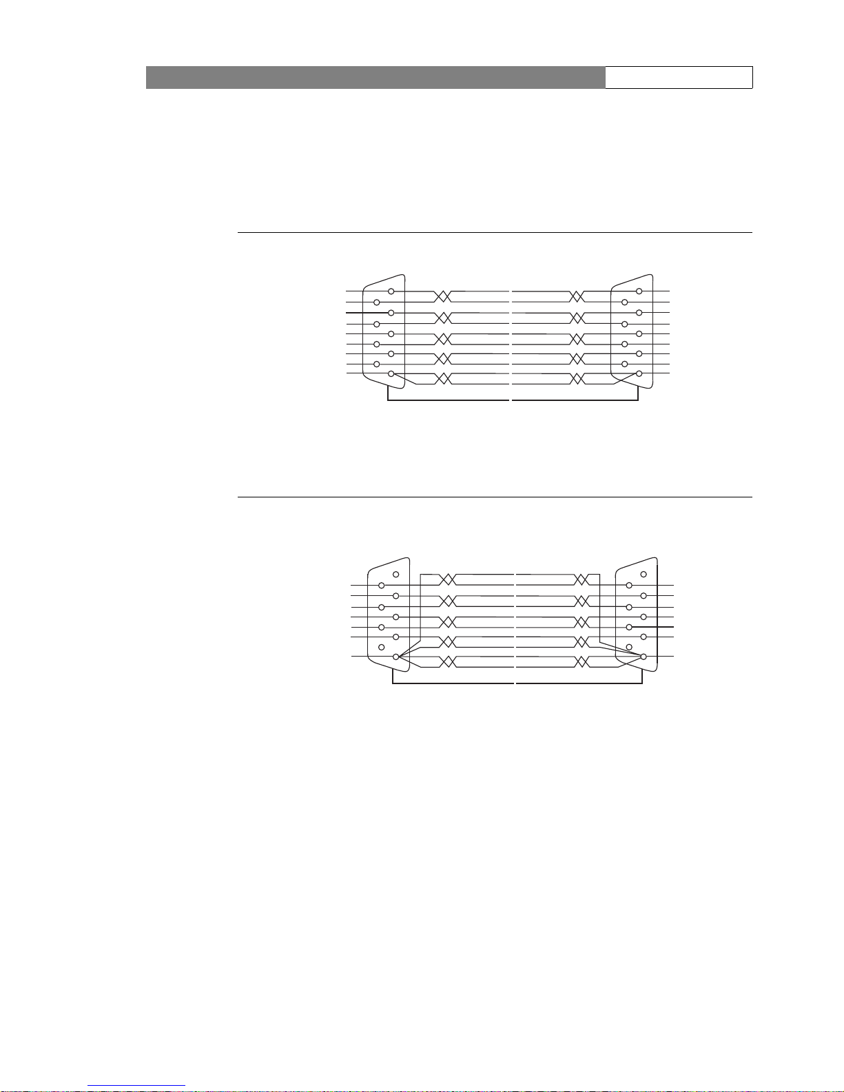
1.4 .2 Custom length cables
To create your own custom length RS-422 remote control cable use the following wiring
diagrams (for cable runs up to 50m or 100m respectively):
Figure 0-1. RS-422 serial cable type 1 (twisted pair; 0 to 50 m)
Figure 0-2. RS-422 serial cable type 2 (twisted power; 0 to 100 m)
Base Station
OCP 400/10
Ground
Ground
Return A
Return B
Out B
Out A
Ground
Ground
OCP power
(+ On Air 1,
On Air 2)
Ground
Out A
Out B
Return B
Return A
Ground
Ground
OCP Power
(+ On air1,
On AIR 2)
Ground
5
4
3
2
1
6
7
8
9
5
4
3
2
1
6
7
8
9
Cable Shield
Base Station OCP 400/10
Ground
Return A
Return B
Out B
Out A
Ground
OCP Power
(+ On Air1,
On Air2)
Ground
Out A
Out B
Return B
Return A
Ground
OCP Power
(+ On Air1,
On Air 2)
5
4
3
2
1
6
7
8
9
5
4
3
2
1
6
7
8
9
Cable Shield
Page 16

LDK 5417 + LDK 4417 User’s Guide | Configuration 4
2 Configuration
2.1 Typical setup
A camera head with an LDK 5417 Triax adapter is connected to a LDK 4417 Base Station using
a Triax cable. The maximum length of cable that can be used without significant degradation of
the video signal is 600m (2,000 ft.) for a 14 mm Triax cable when no prompter is used (see
specifications for other values). The power supply is applied to the Base Station and via the
Triax cable to the camera.
Figure 0-3. Typical Digital Triax system setup
Clear
ND1/4
ND1/16
ND1/64
Clear
Star 4P
Star 6P
Soft Focus
Smart
card
P
o
wer
on
P wel
Tracke rAux
1
2
3
4
A
B
C
D
External Power
Supply (optional)
Triax cable
OCP 400/10
remote control cable
SD Camera Head
LDK 5417 Digital Triax Adapter
LDK 4417 Digital Triax Base Station
Page 17

LDK 5417 + LDK 4417 User’s Guide | Configuration 5
2.2 Connecting a control panel
An OCP 400/10 operational control panel can be connected to the Base Station using an serial
(RS-422) link. Refer to the user’s guides of your camera and the OCP 400/10 for more
information about the functions that are available.
Powering the control panel
The recommend method to power the OCP 400/10 is to use a remote control cable mentioned
in chapter
1. 4 . The control panel is powered by the Base Station via the remote control cable.
It is also possible to use an external power supply. The Grassvalley LDK 5903/00 external
power supply can provide for up to five operational control panels. In this case, any standard
RS-422 cable can be used to connect to the Base Station.
Page 18

LDK 5417 + LDK 4417 User’s Guide | Adapter controls 6
3 Adapter controls
Figure 0-4. Digital Triax adapter LDK 5417 controls
3.1 Powering the camera
The power supply for the camera and Digital Triax adapter is supplied via the triax cable from
the Base Station. The power on indicator (6) lights when power is supplied and the camera
power switch is On.
An output power socket supplies +48 Vdc, 50W maximum for a converter (LDK 5930 or LDK
5940) to supply power for a teleprompter. Refer to chapter
11 “DC/DC converters“ for more
information about power converters.
Call
Mic
Front Rear 48V
Script
Light
Power on
Prompter power
Ext1 Ext2 Ext2
VF VF Ext1
Prod
Off
(Prod)
Ext1
Ext2
Front
Rear
Loc
DIGITAL TRIAX
2
1
3
4
5
8
7
6
Intercom routing switch
selection
5. Audio microphone switch
6. Power On indicator
7. Video output selection switch
8. Viewfinder display signal selection
Page 19

LDK 5417 + LDK 4417 User’s Guide | Adapter controls 7
3.2 Selecting monitoring signals
Viewfinder display signal
The viewfinder can display local or external video signals. The viewfinder display signal
selection switch (8) determines the signal that is displayed in the viewfinder.
Set the first switch to LOC to display the local camera Y signal in the viewfinder. (The Ret.
button on the lens also selects this signal in parallel with this switch.) If set to the other
position, then the second switch determines the signal displayed in the viewfinder.
The second switch selects the signal displayed in the viewfinder when the viewfinder signal
selection switch is not in the LOC position. The signal then displayed is:
– EXT 1 BS external input 1
– EXT 2 BS external input 2.
Video output signal selection
Two BNC connectors on the rear of the adapter carry viewfinder or external signals. To select
the output signal for these connectors use the top switch located underneath them (the
bottom switch is used for the audio microphone).
Figure 0-5. Video output switch and associated connectors
The video output signal selection switch shown above is a three-position switch which
determines the output video signal on the two video output connectors as shown in the
following table:
Switch position VF/Ext1 connector Ext1/Ext2 connector
Set to the right External 1 signal External 2 signal
Centered Viewfinder signal External 2 signal
Set to the left Viewfinder signal External 1 signal
Ext1 Ext2 Ext2
VF VF Ext1
Video output selection
switch
Page 20

LDK 5417 + LDK 4417 User’s Guide | Adapter controls 8
3.3 Audio
A high quality audio channel is available. Set the gain levels (-22 dB to -64 dB) for this channel in
the Audio section of the Install menu. A high-pass filter for the channel can also be switched on
via this menu.
The microphone for channel 1 is connected either to the socket at the front-right of the camera
or to the Mic 1 socket on the triax adapter. A 3-position switch (5) activates the socket at the
front-right or the connector at the rear. The third position selects the rear socket with a
phantom power supply (+48V). The front microphone socket always has a phantom power
supply (+48V).
3.4 Intercom
The production (PROD) intercom channel is sent from the Base Station to the camera
operator's headset. The camera operator's intercom microphone signal is sent to the Base
Station.
The Intercom section of the Install menu contains various settings for these channels. Signals
for left and right headset muffs and sidetone levels can be selected. Intercom microphone
amplification levels, phantom power supply and microphone on/off switches are also available
in this menu.
Additional controls can be found on the back of the adapter.
Intercom microphone routing switch
This 3-position switch (1) routes the camera operator's intercom microphone signal to
production (Prod) or turns off the intercom. The third (momentary) position also routes the
intercom signal to production but operates only as long as it is held in place.
Use the VTR Start button at the front of the camera, or the VTR button on the lens, to send the
camera operator's intercom microphone signal to production, regardless of the position of this
switch.
Production volume control selection
Use this 2-position switch (2) to control the volume of the production signal in the intercom
either at the front of the camera
or at the rear of the adapter.
Intercom headset volume control
This control adjusts the volume of the production signal to the camera operator's headset
when selection switch (2) is in the REAR position.
Switch position Camera front-right connector Adapter rear connector
Set to the right No input Active input with +48V
Centered No input Active Input
Set to the left Active input with +48V No input
Page 21

LDK 5417 + LDK 4417 User’s Guide | Adapter connectors 9
3.5 Communication
Call button
Press this momentary button (4) to send a signal to the control panels calling for attention. The
ND/RE indicator in the 1.5-inch viewfinder shows when a call signal is sent or received.
4 Adapter connectors
Figure 0-6. Digital Triax adapter connector location
Do not allow system earth currents to exceed 1.5A in the outer shield of the Triax cable or 0.2A
in other cable shields. To avoid excessive earth currents in a Triax system, galvanically separate
the power earth connection of equipment connected to the camera from the camera earth.
Call
Mic
Front Rear 48V
Script
Light
Power on
Prompter power
Ext1 Ext2 Ext2
VF VF Ext1
Prod
Off
(Prod)
Ext1
Ext2
Front
Rear
Loc
DIGITAL TRIAX
Triax connector
Ext1/Ext2 video output
Viewfinder/Ext1 video
output
Script light power
Intercom headset
Audio microphone 1
input
DC power supply
output
Page 22

LDK 5417 + LDK 4417 User’s Guide | Adapter connectors 10
4.1 Triax connector
Figure 0-7. Triax connector
4.2 Ext1/Ext2 video output connector
Figure 0-8. External 1 / External 2 video output connector
4.3 Viewfinder / External 1 video output connector
Figure 0-9. Viewfinder / External 1 video output connector
Centre pin
O
uter shield Inner shie
ld
1. Centre pin: Power and signals
2. Inner shield: Return
3. Outer shield: Camera housing GND
Panel view (X100)
This socket provides a 1.0 Vpp external video signal from
the Base Station (output signal is selectable).
BNC connector: panel view (X105)
This socket provides a 1.0 Vpp output viewfinder signal
or the external 1 video signal from the Base Station.
Page 23

LDK 5417 + LDK 4417 User’s Guide | Adapter connectors 11
4.4 Script light power supply socket
Figure 0-10. Script light power supply output connector
4.5 DC power output socket
Figure 0-11. DC power output connector
4.6 Audio microphone 1 connector
Figure 0-12. Audio microphone 1 connector
3
1
2
1. +12 Vdc (maximum dissipation 3W)
2. Power return
3. Shield
Fischer 3-pole female: panel view
2
1
4
3
1. +48 Vdc (max. 50W)
2. -5 Vdc
3. Ground
4. Ground
This connector can be used to supply a DC/DC
converter (LDK 5930/5940) to supply power for a
teleprompter.
Lemo 4-pole female: panel view
3
1
2
1. Audio Screen
2. Audio In signal
3. Audio Return signal
Microphone impedance >200 ohm
Sensitivity range: -64 to -24 dBu
A phantom power supply of +48 Vdc can be supplied to
the microphone via this connector. To select this use the
Audio Microphone switch (5) at the rear of the adapter.
XLR 3-pole female; panel view
Page 24

LDK 5417 + LDK 4417 User’s Guide | Camera install menu 12
4.7 Intercom headset connector
Figure 0-13. XLR intercom headset connector
5 Camera install menu
4
1
2
3
5
1. Microphone return
2. Microphone
3. Telephone return
4. Telephone left
5. Telephone right
Microphone level: -60 dBu / -20 dBu switchable
Microphone impedance: >600 Ohm
Telephone level: +6 dBu nominal
Telephone output impedance: <50 Ohm
XLR 5-pole female; panel view (X104)
Main menu items Purpose
Disable Camera on/off
IR receiver on/off
OnAir Lamp on/off
Intercom set intercom values (sidetone, gain, phantom power)
Audio set gain and filter
Aspect ratio select aspect ratio values
Exposure set lighting and clear scan values
Gain preset set gain preset values
Autowhite set autowhite speed and gain
Quick Smart Touch on/off
Heater on/off switch for SuperXpander heater
Classic Mode set on for classic control
Text insert switches text insert on/off
Buttons assign functions to buttons
Page 25

LDK 5417 + LDK 4417 User’s Guide | Base Station 13
6 Base Station
6.1 Dimensions, weight
.
Weight: Approximately 7 kg
ON AIR
MAINSCAMERA
ON
OFF
CABLE
OPEN
CCU
POWER
I
O
RCP
SOUND/
AUX
CAM.LOCK
GENLOCK/
VIDEO
FINE
COARSE
EXT.REF.
H
SC
CAM. OK
TRIAX
SC/H
FRONT
PORCH
ON AIR
MAINSCAMERA
ON
OFF
CABLE
OPEN
CCU
POWER
I
O
RCP
SOUND/
AUX
CAM.LOCK
GENLOCK/
VIDEO
FINE
COARSE
EXT.REF.
H
SC
CAM. OK
TRIAX
SC/H
FRONT
PORCH
218
264
246
57
3
9
0 (with
connect
o
rs)
Page 26

LDK 5417 + LDK 4417 User’s Guide | Base Station 14
6.2 Installation of Base Station in rack
The Base Station is fitted in a 19"rack:
1. Either alone or with an accessory of dimension 1/2 19" (vectorscope, oscilloscope, etc.)
using the assembly kit for Base Station in 19" racks, part number LDK
5108.
2. Or two Base Stations side by side using kit part number LDK 5107.
Installation of a Base Station with a 1/2 19" accessory
Equipment and tools required:
• Rack installation kit part number LDK 5108 containing various accessories,
• A screwdriver.
Fitting of accessory to the left of the Base Station
1. Remove the LH lug from the Base Station by unscrewing both attaching screws.
2. Couple the accessory rack to the LH side of the Base Station with the lugs located at the
back of the Base Station.
accessory rack
Page 27

LDK 5417 + LDK 4417 User’s Guide | Base Station 15
3. Tighten the six 4 mm dia. screws with the allen wrench from inside the accessory rack to
attach it to the Base Station.
4. Place the front cover panel against the left-hand edge of the Base Station (only one
position is correct).
5. Tighten both the 3 mm dia. screws with the screwdriver from inside the accessory rack to
fit the front cover.
6 screws F/90HC M4x5
allen wrench
front cover panel
2 screws F/90 M3x4
Page 28

LDK 5417 + LDK 4417 User’s Guide | Base Station 16
6. Attach the LH lug of the Base Station (removed in 1) to the left of the accessory rack.
7. Place the accessory in the accessory rack (accessory attachment is to be adapted
according to its type and brand).
8. Place the Base Station + accessory in the 19" rack at the desired location and attach by
means of the two lugs.
Fitting of accessory rack to the right of the Base Station
The principle is identical to the previous procedure, but the six 4 mm dia. screws joining the
two assemblies are to be fitted from inside the Base Station. This implies that the Base Station
power supply unit must be removed.
1. Remove the right-hand lug from the Base Station by unscrewing both attaching screws.
2. Couple the accessory rack to the RH side of the Base Station, with the lugs located at the
front of the Base Station.
3. Remove the power supply unit by unscrewing the 3 attaching screws.
4. Tighten the six 4 mm dia. screws using the screwdriver from inside the Base Station
(power supply unit removed) to attach the accessory rack to the Base Station.
5. Place the front cover against the right-hand edge of the Base Station (only one position
correct).
6. Tighten both 3 mm dia. screws using the screwdriver from the inside of the Base Station
to attach the front cover.
7. Attach the RH lug of the Base Station (removed in step 1) to the right of the accessory
rack.
8. Place the accessory in the accessory rack (accessory attachment is to be adapted
according to its type and brand).
Page 29

LDK 5417 + LDK 4417 User’s Guide | Base Station 17
9. Place the Base Station + accessory assembly in the 19" rack at the location required and
attach it using both lugs.
Fitting two Base Stations in a rack
Equipment and tools required:
• Reference kit LDK 5107.
• One screwdriver.
1. Remove the right-hand lug from the Base Station located to the left by unscrewing both
the attaching screws.
2. Remove the left-hand lug from the Base Station located on the right by unscrewing both
the attaching screws.
3. Remove the Base Station power supply located to the left by unscrewing the 3 attaching
screws.
4. Place the front cover against the left-hand side of the Base Station located to the right
(only one position correct).
Page 30

LDK 5417 + LDK 4417 User’s Guide | Base Station 18
5. Tighten both the 3 mm dia. screws using the screwdriver to attach the front cover.
6. Place both Base Stations side by side.
7. Tighten the six 4 mm dia. screws with the screwdriver from inside the Base Station to the
left (power supply unit removed).
8. Place both Base Stations in the 19" rack at the required location and attach it using both
lugs.
2 screws F/90 M3x4
6 screws F/90HC M4x5
allen wrench
Page 31

LDK 5417 + LDK 4417 User’s Guide | Mains power supply 19
7 Mains power supply
7. 1 Adapting the Base Station to the mains voltage
According to equipment serial number, the power supplies equipping the Base Station are:
• Bivoltage (fitted with an automatic switching system: 100 to 125 V AC and 200 to 240 V
AC 50 or 60 Hz). In this case, no adaptations are required in terms of mains voltage.
• Or monovoltage 100 to 125V AC or 200 to 240V AC 50 or 60 Hz.
Caution
Before connect the Base Station to the mains, to make sure of the equipment operation
voltage. This voltage is indicated on the label located on the Base Station rear panel.
7. 2 Fuse changing
The fuse is located in the mains connector on the back of the Base Station.
• Disconnect the mains plug for access to fuse.
• This connector also contains a spare fuse.
Fuse type:
110V or 220V: Value T 6,3 AH 250V Fuse reference: T9000671
2 fuses:
• Equipment protection fuse.
• Spare fuse.
Page 32

LDK 5417 + LDK 4417 User’s Guide | Base Station connections 20
8 Base Station connections
8.1 Back panel
VIDEO RET 1
PROMPTER
VIDEO RET 2
GENLOCK
EXT. REF.
COMPOSITE
V. B. S.
1
1
2
23
SERIAL DIGITAL OUTPUT
OUTPUT
INPUT
CAMERA
INTERCOM
MIC OUTPUT
REMOTE
TALLY
2
3
1
N
DATA + DC OUT
53V
3A MAX
T6,3A H 250V
6
7
8
9
10
11
1
2
3 4 5
Page 33

LDK 5417 + LDK 4417 User’s Guide | Base Station connections 21
1. Mains socket and fuses
Connection to mains cable
According to equipment serial number, the power
supplies equipping the Base Station are:
Bivoltage (fitted with an automatic switching system: 100
to 125 V AC and 200 to 240 V AC 50 or 60 Hz). In this
case, no adaptations are required in terms of mains
voltage.
Or monovoltage 100 to 125V AC or 200 to 240V AC 50 or
60 Hz.
Before connecting the Base Station to the mains, to make
sure of the equipement operation voltage. This voltage is
indicated on the label located on the Base Station rear
panel.
FUSE CHANGING
The fuse is located in the mains connector on the back of
the Base Station.
Disconnect the mains plug for access to fuse.
This connector also contains a spare fuse.
2. «MIC OUT» receptacle
Audio output from ambient microphone connected to
camera.
The nominal output level is 0 dB. To modify this level,
refer to the «INSTALLATION» Chapter 10.
N
1
3
2
2 fuses:
- Equipment protection fuse
- Spare fuse.
Fuse type:
110V or 220V: Value T 6,3 AH
250V
P/N: T9000671
1 : Neutral
2 : Ground (connected to chassis ground)
3 : Phase
2
3
1
Male receptacle
Type: XLR-3-32
P/N: 91.355.161
Corresponding socket
Type: XLR-3-11C
P/N: 91.355.160
1 : GND
2 : MIC X OUT
3 : MIC Y OUT
Page 34

LDK 5417 + LDK 4417 User’s Guide | Base Station connections 22
«INTERCOM» receptacle
Connection of intercommunication network between
the Cameraman and producer.
The nominal input and output levels are 0 dB. To alter
these levels, refer to the «INSTALLATION» Chapter 10.
The link may be «4-wire» or «RTS».
Refer to the «INSTALLATION» Chapter 10.
3. «REMOTE» receptacle
Connection of remote control panel.
The link is an RS-422 link:
The «PV RCP» 12 V voltage is used for powering the
panel (Pmax = 6W).
The «ON AIR1» and «ON AIR2» signals to the OCP and
the camera are added to the «PV RCP».
INTERCOM
1
69
5
Female receptacle
Type: DEP09S400T
P/N: T9001515
Corresponding socket
Type: PMD2T09+ZHE5-M2
P/N: 99.155.568
1 : GND
2 : IN Y
3 : OUT X
4 : CH1 RTS
5 : CH2 RTS (Not used)
6 : Not connected
7 : IN X
8 : OUT Y
9 : GND
INTERCOM
CH1
RTS
Y X
OUT
Y X
IN
1
69
5
REMOTE
1
69
5
Female receptacle
Type: DEP09S400T
P/N: T9001515
Corresponding socket:
Type: PMD2T09+Z-HE5-M2
P/N: 99.155.568
1 : GND
2 : RETURN A2
3 : OUT B2
4 : GND
5 : PV RCP
6 : GND
7 : RETURN B2
8 : OUT A2
9 : GND
BS
OCP
Return A
Return B
Out A
Out B
PV RCP
Ground
1
5
3
8
7
2
1
5
3
8
7
2
Page 35

LDK 5417 + LDK 4417 User’s Guide | Base Station connections 23
4. «TALLY» receptacle
Connection of «ON AIR1» and «ON AIR2» signals.
The «ON AIR1» and «ON AIR2» signals received may be
«VOLTAGE» or «CONTACT» signals. Adaptation of the
equipment to the various types of control is described in
the «INSTALLATION» Chapter.
Example: «CONTACT» type ON AIR1.
Example: «VOLTAGE» type ON AIR1
5. «VIDEO RET 1» receptacles
The «Loopedthrough» No. 1 return video input. The signal
is not loaded into the Base Station. Input level is 1
Vpp ~
75 Ohm.
Transmission of the «RET 1» video of the camera
depends on the triaxial cable length. Refer to the
specifications chapter.
6. «PROMPTER VIDEO RET 2» receptacles.
The No. 2 return video (or «PROMPTER») input is
«loopedthrough». The signal is not loaded in the Base
Station. Input level: 1
Vpp ~ 75 Ohm
Transmission of the «RET 2» video to the camera
depends on the length of the triaxial cable. Refer to the
SPECIFICATION chapter.
7. «TRIAX» receptacle
Connection of the TRIAXIAL cable connected to the
camera control unit.
The cable transmits the various signals and the camera
power supply.
Output voltage: 52 Vdc; Imax: 3 A
TALLY
1
6
9
5
Female receptacle
Type: DEP09S400T
P/N: T9001515
Corresponding socket
Type: PMD2T09+Z-HE5M2
P/N: 99.155.568
1 : Not used
2 : ON AIR1 NEG
3 : ON AIR2 POS
4 : GND
5 : Not connected
6 : Not used
7 : ON AIR1 POS
8 : ON AIR2 NEG
9 : Not connected
TALLY
1
6
9
5
ON AIR1
TALLY
1
6
9
5
-
+
U
ON AIR1
U=5 - 48V
VIDEO RET 1
Receptacles
Type: P2189-A
P/N: T9003306
PROMPTER
VIDEO RET 2
Receptacles
Type: P2189-A
P/N: T9003306
CAMERA
Receptacles:
•LEMO 75
•LEMO 50
•FISCHER
• KINGS
•DAMAR HAGEN
Page 36

LDK 5417 + LDK 4417 User’s Guide | Base Station connections 24
8. «GEN LOCK EXT. REF» receptacles
The «looped through» reference signal input. The signal is
not loaded in the Base Station. Input level: 1
Vpp ~ 75
Ohm.
As a general rule, the signal must be of "composite video"
type to control the composite and digital signals at the
output from the Base Station (link J92 set to ON on the
GENLOCK/VIDEO board.
If the reference signal does not a "Burst", place link J92 on
the GENLOCK/VIDEO board to OFF position. The
composite signal subcarrier is then slaved with respect to
the composite sync signal.
Refer to the INSTALLATION Chapter 10 for equipment
phase alignment.
9. «COMPOSITE V.B.S.» receptacles.
Encoded PAL or NTSC signal outputs. Levels: 1 Vpp ~ 75
Ohm.
10. «SERIAL DIGITAL OUTPUT» receptacles
Serial digital signal outputs:
4:2:2, 270 Mbits.
GENLOCK
EXT. REF.
Receptacles
Type: P2189-A
P/N: T9003306
CVBS
12
Receptacles
Type: P2189-A
P/N: T9003306
12 3
SERIAL DIGITAL OUTPUT
Receptacles+cables
Type:
98230x-021-009.0
P/N: T6000091
Page 37

LDK 5417 + LDK 4417 User’s Guide | Base Station controls 25
9 Base Station controls
9.1 Front panel
ON AIR
MAINSCAMERA
ON
OFF
CABLE
OPEN
CCU
POWER
I
O
RCP
SOUND/
AUX
CAM.LOCK
GENLOCK/
VIDEO
FINE
COARSE
EXT.REF.
H
SC
CAM. OK
TRIAX
SC/H
FRONT
PORCH
1
2 3 4 5 6 7
1. «CAM OK» indicator light
Normally lit, this indicator light indicates that the digital signal
from the camera is present.
2. «H, SC, SC/H» adjustments
Adjustments of the digital video horizontal phase at the
equipment output.
Adjustment of the subcarrier and horizontal phases for
encoded videos at the equipment output.
«FRONT PORCH» adjustments of the encoded videos at the
equipment output.
Refer to the «INSTALLATION» Chapter 10 for a complete
description of these adjustments.
3. «CAM LOCK, EXT. REF» indicator lights
CAM LOCK: Normally lit, this indicator light indicates that the
camera phase is controlled by the Base Station.
EXT REF.: When lit, this indicator light indicates presence of
an external sync signal on the «GEN LOCK» receptacle of the
Base Station.
CAM. OK
FINE
COARSE
H
SC
SC/H
FRONT
PORCH
CAM.LOCK
EXT.REF.
Page 38

LDK 5417 + LDK 4417 User’s Guide | Base Station controls 26
4. «RCP» indicator light
This indicator light lights to indicate activity on the link
between Camera and OCP connected on the «REMOTE»
receptacle of the Base Station.
5. «CAMERA: ON, OFF, CABLE OPEN» indicator
lights
ON:
Normally and permanently lit, this light indicates that the
camera is powered.
This indicator light when flashing indicates excessive
consumption at the camera. The current in the triaxial cable is
then between 3 A and 3.3 A. Above 3.3 A, the Base Station
power supply cuts out. rearming is obtained automatically 4
times. If the overload persists, the cut-out becomes
permanent. An equipment on/off is then required to start the
equipment operating again.
OFF:
This permanently lit indicator light indicates that the camera
power is off.
When flashing, this indicator light indicates that the camera
consumption is excessively low. The current in the triaxial
cable is then between 0.1 A and 0.4 A.
CABLE OPEN:
This normally extinguished indicator light indicates that the
triaxial cable is not connected to the camera or to the back
panel of the Base Station.
6. «ON AIR» indicator light
When lit, this light indicates that the equipment is switched to
the antenna («ON AIR1»).
7. «MAINS» switch
The equipment master on/off switch:
«I»: The equipment is operating.
«O»: The equipment is not operating.
RCP
CAMERA
ON
OFF
CABLE
OPEN
ON AIR
MAINS
I
O
Page 39

LDK 5417 + LDK 4417 User’s Guide | Base Station installation 27
10 Base Station installation
10.1 Audio
The «MIC 1» sound output level can be adjusted on the «SOUND/AUX» card over the range 6
dB to + 18 dB. This adjustment is made using selector switch S500 «0 dB + 12 dB» and
«LEVEL» potentiometer R500.
10.2 Intercom
The «INTERCOM» link of the sound engineer’s control room may be of the 4-wire or RTS/
CLEARCOM type.
4-wire link
• Selector switches S560 and S50 on the «SOUND/AUX» board of the Base Station should
be set to 4W.
• The «INTERCOM» sound output level can be adjusted on the «SOUND/AUX» board of the
Base Station over the range - 6 dB to + 18 dB. The adjustment is performed using «0 dB
+ 12 dB» selector switch S540 and «LEVEL» potentiometer R540.
• The «INTERCOM» sound input level can be adjusted on the «SOUND / AUX» board of the
Base Station over the range - 6 dB to + 18 dB. The adjustment is made using the «0 dB +
12 dB» selector switch S581 and the «LEVEL» potentiometer R580.
☞
Note
When the 4-wire link is in use, the RTS/CLEARCOM intercom link is unavailable.
ON AIR 1
S800
S801
R500
S500
CONTACT
+12dB0dB
VOLTAGE
MIC-2 MIC-1
OUT LEVEL
R540
S540
+12dB0dB
+12dB
0dB
4W
RTS
OUT LEVEL
CCU->CAM CAM->CCU
ON AIR 2
S900
S581
R580
S580
S560
S901
CONTACT
OUT LEVEL
VOLTAGE
SOUND / AUX PCB
Page 40

LDK 5417 + LDK 4417 User’s Guide | Base Station installation 28
RTS/CLEARCOM link
• Selector switches S560 and S580 on the «SOUND/AUX» board of the Base Station must
be set to RTS
• The RTS «INTERCOM» sound input level can be adjusted on the «SOUND/AUX» board of
the Base Station over the range - 6 dB to + 18 dB. The adjustment is made using the «0
dB +12 dB» selector switch S581 and «LEVEL» potentiometer R580.
☞
Note
When the RTS/CLEARCOM link is in use, the 4-wire intercom link is unavailable.
The RTS/CLEARCOM link must be loaded with 200 Ohm.
10.3 Video
The various adjustments are made on the «GENLOCK/VIDEO» board.
ON AIR 1
S800
S801
R500
S500
CONTACT
+12dB0dB
VOLTAGE
MIC-2 MIC-1
OUT LEVEL
R540
S540
+12dB0dB
+12dB
0dB
4W
RTS
OUT LEVEL
CCU->CAM CAM->CCU
ON AIR 2
S900
S581
R580
S580
S560
S901
CONTACT
OUT LEVEL
VOLTAGE
SOUND / AUX PCB
CAM.LOCK
GENLOCK/
VIDEO
FINE
COARSE
EXT.REF.
H
SC/H
SC
FRONT
PORCH
«GENLOCK VIDEO» board switches
«GENLOCK VIDEO» board adjustments
Factory switches
Rotary switch CO1160 is for factory testing only. For normal operation, this switch
must be set to position 0.
Switch S300 is for factory use only; do not change its position.
Rotary switch CO1140 is for special applications; do not change its position.
S1151
CO1150
CO1160
S300
CO1140
Page 41

LDK 5417 + LDK 4417 User’s Guide | Base Station installation 29
Composite video output standard selection
This selection is made using rotary switch CO1150. Select the position corresponding to the
standard you require.
Equipment phase alignment with a digital installation
Equipment slaved to an external reference on «GENLOCK» input
The reference signal should be a black video signal with or without burst delivered by a
Broadcast generator and terminated with 75 Ohm load.
Horizontal phase alignment of the digital output signal
The horizontal phase of the digital output signal with respect to the external reference signal is
adjusted using the «
H COARSE» and «H FINE» thumbwheels. The range of variation
depends on the position of the lower switch of S1151.
S1151 up position (FINE):
• «H COARSE»: Adjustment in steps of 592 ns.
• «H FINE»: Adjustment in steps of 37 ns.
The range of variation of the digital output signal with respect to the reference signal is
approximately -6.4 μs + 2.7 μs.
S1151 down position (COARSE):
• «H COARSE»: Adjustment in steps of 1184 ns.
• «H FINE»: Adjustment in steps of 74 ns.
The range of variation of the digital output signal with respect to the reference signal is
approximately -12.8 μs + 5.4 μs.
Ta bl e 0-14. Standard selection
Position Standard
0 NTSC
1 PAL M
2 PAL BG H I
3 PAL N
4 to F Not used
Reference with Black Burst (BBS)
Reference without Black Burst
0.3 V
0.3 V
0.3 V
Page 42

LDK 5417 + LDK 4417 User’s Guide | Base Station installation 30
.
If the composite video output is used as a monitoring output, it is recommended to set the
upper switch of S1151 to «OFF» to disable the Subcarrier genlock. In this case, the output
composite signal carrier is internally slaved with respect to the sync signals.
If necessary, the «SC phase« and «Front porch» alignment can be adjusted using the «SC/H»
and «FRONT PORCH» thumbwheels.
Equipment without external reference (free mode)
Set the upper switch of S1151 to «OFF». The «H COARSE» and «H FINE» thumbwheels
are inactive.
If the composite video output is used as a monitoring output, and if necessary, the «SC phase«
and «Front porch» alignment can be adjusted using the «SC/H» and «FRONT PORCH»
thumbwheels. The output composite signal carrier is internally slaved with respect to the sync
signals.
Phase alignment with a analog installation
External reference on «GENLOCK» input with blackburst
The reference signal should be a black video signal with burst delivered by a Broadcast
generator (stable SC/H) and terminated with 75 Ohm load.
Set the upper switch of S1151 to «ON». In this case, the output composite signal subcarrier is
slaved to the reference burst.
The horizontal phase of the composite signal with respect to the external reference signal is
adjusted using the «
H COARSE» and «H FINE» thumbwheels. The range of variation
depends on the position of the lower switch of S1151.
S1151 up position (FINE):
• «H COARSE»: Adjustment in steps of 592 ns.
• «H FINE»: Adjustment in steps of 37 ns.
The range of variation of the composite signal with respect to the reference signal is
approximately -6.4 μs + 2.7 μs.
S1151 down position (COARSE):
• «H COARSE»: Adjustment in steps of 1184 ns.
• «H FINE»: Adjustment in steps of 74 ns.
-
)
8
5
)
8
-
)
8
5
)
8
Reference
Digital
S1151 : FINE = -6.4µs to +2.7µs
S1151 : WIDE = -12.8µs to +5.4µs
REF
Page 43

LDK 5417 + LDK 4417 User’s Guide | Base Station installation 31
The range of variation of the composite signal with respect to the reference signal is
approximately -12.8 μs + 5.4 μs.
.
The output composite signal subcarrier phase with respect to the external reference signal
(BBS) is adjusted using thumbwheel «
SC».
Adjustment of the composite signal front porch width is made using the «FRONT PORCH»
thumbwheel.
☞
Note
This setting has no effect on horizontal blanking width
.
External reference without blackburst
The reference signal should be a black video signal and terminated with 75 Ohms load.
Set the upper switch of S1151 to «OFF». The output composite signal carrier is internally
slaved with respect to the sync signals.
REFERENCE VIDEO
REF
COMPOSITE VIDEO
S1151 : FINE = -6.4µs to +2.7µs
S1151 : WIDE = -12.8µs to +5.4µs
PAL 1,5 ±0,3 μs (1,65 μs ±0,1 μs PAL I)
NTSC 1,5 ±0,1 μs
Composite outputs 1 and 2
Page 44

LDK 5417 + LDK 4417 User’s Guide | Base Station installation 32
The horizontal phase of the composite signal with respect to the external reference signal is
adjusted using the «
H COARSE» and «H FINE» thumbwheels:
The SC/H phase alignment of the composite output signal is adjusted using the «SC/H»
thumbwheel.
Adjustment of the front porch of the composite signal is made using the «FRONT PORCH»
thumbwheel.
Equipment without external reference (free mode)
The «H COARSE» and «H FINE» thumbwheels are inactive.
The output composite signal SC/H phase alignment is adjusted using the «SC/H»
thumbwheel.
The output composite signal front porch duration is adjusted using the «FRONT PORCH»
thumbwheel.
10.4 Adaptation of BS to external on-air signal controls from
the studio
The «ON AIR 1» and «ON AIR 2» main and secondary studio commands received by the Base
Station may be of two different forms:
• A DC voltage of between + 5 Volts and + 48 Volts.
• A closed loop (contact).
Adaptation is made in the «SOUND/AUX» board of the Base Station.
Depending on the type of signal from the mixer, set selector switches S800 and S801 (ON AIR
1) and S900 and S901 (ON AIR 2) to the positions indicated in the figure.
ON AIR 1
S800
S801
R500
S500
CONTACT
+12dB0dB
VOLTAGE
MIC-2 MIC-1
OUT LEVEL
R540
S540
+12dB0dB
+12dB
0dB
4W
RTS
OUT LEVEL
CCU->CAM CAM->CCU
ON AIR 2
S900
S581
R580
S580
S560
S901
CONTACT
OUT LEVEL
VOLTAGE
SOUND / AUX PCB
S800-S801 Control
Contact (up) Loop (contact)
Voltage (down) +5 V to +48 V
Page 45

LDK 5417 + LDK 4417 User’s Guide | Base Station installation 33
☞
Note
Selector switches S1000 and S1001 are not used.
S900-S901 Control
Contact (up) Loop (contact)
Vol tage (down ) +5 V to +48 V
Page 46

LDK 5417 + LDK 4417 User’s Guide | DC/DC converters 34
11 DC/DC converters
These converters, which are available as an option, are attached to the camera baseplate. The
can be used to supply teleprompters for example. They provide a regulated voltage of 12 V or
24 V (depending on converter type) and a power of 50 W. The maximum power produced by
the converter is ensured with a maximum triax length of :
– Type A triax (diameter 9 mm): 90 metres.
– Type B triax (diameter 13 mm): 150 metres.
LDK 5930 is the 12V version; LDK 5940 is the 24V version.
Figure 0-15. DC/DC converter
Attaching screws to the camera
baseplate or optional fixing plate
177
131
110
All dimensions in mm
Page 47

LDK 5417 + LDK 4417 User’s Guide | DC/DC converters 35
1.
«12V/50W» or «24V/50W» receptacle
Regulated voltage output.
The voltage on output 4 of the connector is 12 or 24 V
depending on the type of converter. The maximum power
produced is 50 Watts.
Note:
The maximum power (50W) produced by the external
converter connected on the camera "DC OUT" is ensured with
a maximum triaxial cable length.
2.
«DC IN» receptacle
Connection of cable connecting the converter to the camera.
Converter supply:
The voltage received on this receptacle varies between 30 V
DC and 52 V DC depending on:
- The length and type of the triaxial cable
- The power consumed by the converter.
The -5 V is used to delay starting of the converter on camera
power on to prevent the Channel Control Unit power supply
tripping out.
If a DC-to-DC converter (even unloaded) is connected to the
camera while operating, the safety system will cause the
camera to trip out.
The converter must be connected to the
camera with camera power off.
3.
DC out indicator
Light: the DC voltage is present on the converter output.
1
2
3
4
DC IN
3
17
37
1
2
Receptacle
Type: XLR-4-31
P/N: 91538047
Corresponding socket
Type: XLR-4-12C
P/N: 91647565
1 : GND
2 : N.C.
3 : N.C.
4 : +V OUT (12V OR 24V(
1
2
3
4
DC IN
132
4
Receptacle
Type: EMD04+Z-ERNC
P/N: T9003619
Corresponding socket
Type: FFA-1S-304-CLAC52
P/N: T9003618
1 : +48V IN
2 : -5V IN
3 : GND
4 : GND
Page 48

LDK 5417 + LDK 4417 User’s Guide | DC/DC converters 36
11. 1 Installation
To attach the DC/DC convertor to the camera proceed as follows:
• Ensure power is disconnected.
• Attach the LDK6506 fixing plate to the tripod plate using the supplied bolted screws (A).
• To ensure the converter’s thermal isolation from the tripod attach the screws in the exact
following order:
1. Tighten screw (B).
2. Tighten two screws (C).
• Connect the cable from the DC IN input of the converter to the DC OUT output of the
camera. This cable is supplied with the converter.
• Connect the equipment to be supplied to the "DC OUT 12V/50W" or "DC OUT 24V/
50W"ouput depending on the converter type used.
Figure 0-16. Installing the DC/DC converter
☞
Note
The LDK 6506 Fixing Plate is always required when using the LDK5930/5940 DC/DC convertor
with LDK cameras.
Screws C
Screw B
DC/DC convertor
Tripod plate
LDK 6506 Fixing plate *
Screws A
 Loading...