

Page 1
Camera
Communication
On Air Base
Station
Ready
Mains
Camera
Power On
Test Connected
User’s Guide
3922 496 31761 May 2011 v1.0
LDK 4410 + LDK 5420
3G Fiber Transmission System
Page 2

Copyright
Trademarks
Website
Copyright Grass Valley Nederland B.V. 2011. Copying of this document and
giving it to others, and the use or communication of the contents thereof, are
forbidden without express authority. Offenders are liable to the payment of
damages. All rights are reserved in the event of the grant of a patent or the
registration of a utility model or design. Liable to technical alterations in the
course of further development.
Grass Valley is a trademark of Grass Valley, Inc. All other tradenames
referenced are service marks, trademarks, or registered trademarks of their
respective companies.
Visit the Grass Valley public website to download the latest user’s guide
updates and additional information about your broadcast product:
www.grassvalley.com
Page 3

Table of contents
Chapter 1 – Introduction
1.1 Welcome. . . . . . . . . . . . . . . . . . . . . . . . . . . . . . . . . . . . . . . . . . . . . . . . . . . . . . . . . . . .11
1.1.1 About this manual . . . . . . . . . . . . . . . . . . . . . . . . . . . . . . . . . . . . . . . . . . . . . . .11
1.1.2 Related documents . . . . . . . . . . . . . . . . . . . . . . . . . . . . . . . . . . . . . . . . . . . . . . 11
1.2 System overview . . . . . . . . . . . . . . . . . . . . . . . . . . . . . . . . . . . . . . . . . . . . . . . . . . . . . 11
1.2.1 Transmission . . . . . . . . . . . . . . . . . . . . . . . . . . . . . . . . . . . . . . . . . . . . . . . . . . . 11
1.2.2 Dockable adapter . . . . . . . . . . . . . . . . . . . . . . . . . . . . . . . . . . . . . . . . . . . . . . . . 12
1.2.3 Base station . . . . . . . . . . . . . . . . . . . . . . . . . . . . . . . . . . . . . . . . . . . . . . . . . . . . 12
1.2.4 Operational controls. . . . . . . . . . . . . . . . . . . . . . . . . . . . . . . . . . . . . . . . . . . . . . 12
1.2.5 Intercom . . . . . . . . . . . . . . . . . . . . . . . . . . . . . . . . . . . . . . . . . . . . . . . . . . . . . .12
1.3 Main features . . . . . . . . . . . . . . . . . . . . . . . . . . . . . . . . . . . . . . . . . . . . . . . . . . . . . . . . 13
Chapter 2 – Base station
2.1 Installation . . . . . . . . . . . . . . . . . . . . . . . . . . . . . . . . . . . . . . . . . . . . . . . . . . . . . . . . . . 15
2.1.1 Control bus . . . . . . . . . . . . . . . . . . . . . . . . . . . . . . . . . . . . . . . . . . . . . . . . . . . . 15
2.1.2 Intercom cabling . . . . . . . . . . . . . . . . . . . . . . . . . . . . . . . . . . . . . . . . . . . . . . . . 15
2.1.3 Studio signalling. . . . . . . . . . . . . . . . . . . . . . . . . . . . . . . . . . . . . . . . . . . . . . . . .16
2.1.4 External audio level control . . . . . . . . . . . . . . . . . . . . . . . . . . . . . . . . . . . . . . . . 21
2.1.5 Private data . . . . . . . . . . . . . . . . . . . . . . . . . . . . . . . . . . . . . . . . . . . . . . . . . . . . 21
2.2 Base station menu . . . . . . . . . . . . . . . . . . . . . . . . . . . . . . . . . . . . . . . . . . . . . . . . . . . . 22
2.2.1 Using the rotary/push button . . . . . . . . . . . . . . . . . . . . . . . . . . . . . . . . . . . . . . . 22
2.2.2 Using the OCP . . . . . . . . . . . . . . . . . . . . . . . . . . . . . . . . . . . . . . . . . . . . . . . . . . 23
2.2.3 Menu navigation . . . . . . . . . . . . . . . . . . . . . . . . . . . . . . . . . . . . . . . . . . . . . . . . 24
2.3 Intercom setup . . . . . . . . . . . . . . . . . . . . . . . . . . . . . . . . . . . . . . . . . . . . . . . . . . . . . . . 27
2.3.1 Studio interface setup . . . . . . . . . . . . . . . . . . . . . . . . . . . . . . . . . . . . . . . . . . . . 27
2.4 Reference and timing set up. . . . . . . . . . . . . . . . . . . . . . . . . . . . . . . . . . . . . . . . . . . .28
2.4.1 Basic signal processing . . . . . . . . . . . . . . . . . . . . . . . . . . . . . . . . . . . . . . . . . . . 28
2.4.2 Adjustment procedure for HD timing . . . . . . . . . . . . . . . . . . . . . . . . . . . . . . . . 28
2.4.3 Adjustment procedure for SD timing. . . . . . . . . . . . . . . . . . . . . . . . . . . . . . . . .29
Chapter 3 – Camera adapter
3.1 Mounting . . . . . . . . . . . . . . . . . . . . . . . . . . . . . . . . . . . . . . . . . . . . . . . . . . . . . . . . . . .31
3.1.1 General . . . . . . . . . . . . . . . . . . . . . . . . . . . . . . . . . . . . . . . . . . . . . . . . . . . . . . . 31
3.1.2 Detaching. . . . . . . . . . . . . . . . . . . . . . . . . . . . . . . . . . . . . . . . . . . . . . . . . . . . . . 31
3.1.3 Attaching . . . . . . . . . . . . . . . . . . . . . . . . . . . . . . . . . . . . . . . . . . . . . . . . . . . . . . 32
3.1.4 Adjusting the shoulder pad . . . . . . . . . . . . . . . . . . . . . . . . . . . . . . . . . . . . . . . . 32
3.2 Controls and indicators . . . . . . . . . . . . . . . . . . . . . . . . . . . . . . . . . . . . . . . . . . . . . . . . 33
3.2.1 Overview . . . . . . . . . . . . . . . . . . . . . . . . . . . . . . . . . . . . . . . . . . . . . . . . . . . . . . 33
3.2.2 Power . . . . . . . . . . . . . . . . . . . . . . . . . . . . . . . . . . . . . . . . . . . . . . . . . . . . . . . .33
3.2.3 Selecting monitoring signals . . . . . . . . . . . . . . . . . . . . . . . . . . . . . . . . . . . . . . . 34
3.2.4 Using audio . . . . . . . . . . . . . . . . . . . . . . . . . . . . . . . . . . . . . . . . . . . . . . . . . . . . 34
3.2.5 Intercom . . . . . . . . . . . . . . . . . . . . . . . . . . . . . . . . . . . . . . . . . . . . . . . . . . . . . .36
3.2.6 Communication . . . . . . . . . . . . . . . . . . . . . . . . . . . . . . . . . . . . . . . . . . . . . . . . . 37
LDK 4410 + LDK 5420 3G Fiber Transmission System User’s Guide (v1.0) 3
Page 4

Chapter 4 – Transmission
4.1 Base station indicators . . . . . . . . . . . . . . . . . . . . . . . . . . . . . . . . . . . . . . . . . . . . . . . .39
4.2 Transmission diagnostics . . . . . . . . . . . . . . . . . . . . . . . . . . . . . . . . . . . . . . . . . . . . . .41
4.2.1 Monitoring transmission . . . . . . . . . . . . . . . . . . . . . . . . . . . . . . . . . . . . . . . . . .41
4.2.2 Sync/encoder HD board diagnostics . . . . . . . . . . . . . . . . . . . . . . . . . . . . . . . . . 41
4.3 Board locations . . . . . . . . . . . . . . . . . . . . . . . . . . . . . . . . . . . . . . . . . . . . . . . . . . . . . .42
4.3.1 Base station board locations . . . . . . . . . . . . . . . . . . . . . . . . . . . . . . . . . . . . . . . 42
4.3.2 Camera adapter board locations . . . . . . . . . . . . . . . . . . . . . . . . . . . . . . . . . . . .43
4.4 Replacements. . . . . . . . . . . . . . . . . . . . . . . . . . . . . . . . . . . . . . . . . . . . . . . . . . . . . . . .43
4.4.1 Replacing base station fuses . . . . . . . . . . . . . . . . . . . . . . . . . . . . . . . . . . . . . . .43
4.4.2 Replacing base station power supply unit . . . . . . . . . . . . . . . . . . . . . . . . . . . . .45
4.4.3 Replacing base station air filter . . . . . . . . . . . . . . . . . . . . . . . . . . . . . . . . . . . . . 46
Chapter 5 – Menus
5.1 Base station menu . . . . . . . . . . . . . . . . . . . . . . . . . . . . . . . . . . . . . . . . . . . . . . . . . . . .47
5.1.1 Top level. . . . . . . . . . . . . . . . . . . . . . . . . . . . . . . . . . . . . . . . . . . . . . . . . . . . . . .47
5.1.2 Video menu . . . . . . . . . . . . . . . . . . . . . . . . . . . . . . . . . . . . . . . . . . . . . . . . . . . .48
5.1.3 Monitoring menu . . . . . . . . . . . . . . . . . . . . . . . . . . . . . . . . . . . . . . . . . . . . . . . .49
5.1.4 Audio/intercom menu . . . . . . . . . . . . . . . . . . . . . . . . . . . . . . . . . . . . . . . . . . . .50
5.1.5 SDTV menu . . . . . . . . . . . . . . . . . . . . . . . . . . . . . . . . . . . . . . . . . . . . . . . . . . . .51
5.1.6 System menu. . . . . . . . . . . . . . . . . . . . . . . . . . . . . . . . . . . . . . . . . . . . . . . . . . . 52
5.1.7 Files menu . . . . . . . . . . . . . . . . . . . . . . . . . . . . . . . . . . . . . . . . . . . . . . . . . . . . .54
5.1.8 Diagnostics menu . . . . . . . . . . . . . . . . . . . . . . . . . . . . . . . . . . . . . . . . . . . . . . .55
5.2 Camera adapter menu. . . . . . . . . . . . . . . . . . . . . . . . . . . . . . . . . . . . . . . . . . . . . . . . .58
5.2.1 Install menu . . . . . . . . . . . . . . . . . . . . . . . . . . . . . . . . . . . . . . . . . . . . . . . . . . . .58
5.2.2 Diagnostics menu . . . . . . . . . . . . . . . . . . . . . . . . . . . . . . . . . . . . . . . . . . . . . . .62
Chapter 6 – Connectors
6.1 LDK 4410 3G Fiber base station connectors . . . . . . . . . . . . . . . . . . . . . . . . . . . . . . .65
6.1.1 Connector locations . . . . . . . . . . . . . . . . . . . . . . . . . . . . . . . . . . . . . . . . . . . . . .65
6.1.2 Power supply unit . . . . . . . . . . . . . . . . . . . . . . . . . . . . . . . . . . . . . . . . . . . . . . .65
6.1.3 Communication module. . . . . . . . . . . . . . . . . . . . . . . . . . . . . . . . . . . . . . . . . . .66
6.1.4 BNC connector board. . . . . . . . . . . . . . . . . . . . . . . . . . . . . . . . . . . . . . . . . . . . . 68
6.1.5 Transmission module. . . . . . . . . . . . . . . . . . . . . . . . . . . . . . . . . . . . . . . . . . . . .71
6.2 LDK 5420 3G Fiber camera adapter connectors . . . . . . . . . . . . . . . . . . . . . . . . . . . .72
6.2.1 Connector locations back panel . . . . . . . . . . . . . . . . . . . . . . . . . . . . . . . . . . . . .72
6.2.2 Connector locations side panels . . . . . . . . . . . . . . . . . . . . . . . . . . . . . . . . . . . .74
Chapter 7 – Specifications
7.1 LDK 4400 3G Fiber base station specifications . . . . . . . . . . . . . . . . . . . . . . . . . . . . . 77
7.1.1 Technical specifications . . . . . . . . . . . . . . . . . . . . . . . . . . . . . . . . . . . . . . . . . . .77
7.1.2 LDK 4531/30 High Quality SD module. . . . . . . . . . . . . . . . . . . . . . . . . . . . . . . .78
7.1.3 Dimensions . . . . . . . . . . . . . . . . . . . . . . . . . . . . . . . . . . . . . . . . . . . . . . . . . . . .79
7.2 LDK 5420 3G camera adapter specifications . . . . . . . . . . . . . . . . . . . . . . . . . . . . . . .80
7.2.1 Technical specifications . . . . . . . . . . . . . . . . . . . . . . . . . . . . . . . . . . . . . . . . . . .80
7.2.2 Dimensions . . . . . . . . . . . . . . . . . . . . . . . . . . . . . . . . . . . . . . . . . . . . . . . . . . . .81
4 LDK 4410 + LDK 5420 3G Fiber Transmission System User’s Guide (v1.0)
Page 5

End-of-life product recycling
Grass Valley’s innovation and excellence in product design also extends to the programs we’ve established to
manage the recycling of our products. Grass Valley has developed a comprehensive end-of-life product take back
program for recycle or disposal of end-of-life products. Our program meets the requirements of the European
Union’s WEEE Directive and in the United States from the Environmental Protection Agency, individual state or
local agencies.
Grass Valley’s end-of-life product take back program assures proper disposal by use of Best Available Technology.
This program accepts any Grass Valley branded equipment. Upon request, a Certificate of Recycling or a
Certificate of Destruction, depending on the ultimate disposition of the product, can be sent to the requester.
Grass Valley will be responsible for all costs associated with recycling and disposal, including freight, however
you are responsible for the removal of the equipment from your facility and packing the equipment ready for
pickup.
For further information on the Grass Valley product take back system please contact Grass Valley at + 800 80 80
20 20 or +33 1 48 25 20 20 from most other countries. In the US and Canada please call 800-547-8949 or 530478-4148. Ask to be connected to the EH&S Department. In addition, information concerning Grass Valley’s
environmental policy can be found at:
www.grassvalley.com/about/environmental-policy
Packing/unpacking
Inspect the shipping container for evidence of damage immediately after receipt. If the
shipping container or cushioning material is damaged, it should be kept until the contents of
the shipment have been checked for completeness and the units have been checked
mechanically and electrically. The shipping container should be placed upright and opened from
the top. Remove the cushioning material and lift out the contents. The contents of the
shipment should be checked against the packing list. If the contents are incomplete, if there is
mechanical damage or defect, or if the units do not perform correctly when unpacked, notify
your sales or service centre within eight days. If the shipping container shows signs of damage
or stress, notify the carrier as well.
If a unit is being returned to for servicing, try to use the containers and materials of the original
packaging. Attach a tag indicating the type of service required, return address, model number,
full serial number and the return number which will be supplied by your service centre. If the
original packing can no longer be used, the following general instructions should be used for
repacking with commercially available materials:
1. Wrap unit in heavy paper or plastic.
2. Use strong shipping container.
3. Use a layer of shock-absorbing material around all sides of the unit to provide firm
cushioning and prevent movement inside container.
4. Seal shipping container securely.
5. Mark shipping container FRAGILE to ensure careful handling.
LDK 4410 + LDK 5420 3G Fiber Transmission System User’s Guide (v1.0) 5
Page 6

Declaration of conformity
We, Grass Valley Nederland B.V., Kapittelweg 10, 4827 HG Breda, The Netherlands, declare
under our sole responsibility that this product is in compliance with the following standards:
– EN60065 Safety
– EN55103-1:2009 EMC (Emission) for the following environments:
(E1) Residential;
(E2) Commercial and light industrial;
(E3) Urban outdoors;
(E4) Controlled EMC environment, and the rural outdoors environment.
– The average half-cycle r.m.s. inrush currents for this product are:
- 16 A (on intial switch-on);
- 11 A (after a supply interruption of 5 s).
– EN55103-2 EMC (Immunity)
following the provisions of:
– the EMC Directive 2004/108/EC
– the Low Voltage Directive 2006/95/EC
FCC Class A Statement
This product generates, uses, and can radiate radio frequency energy and if not installed and
used in accordance with the instructions, may cause interference to radio communications.
It has been tested and found to comply with the limits for a class A digital device pursuant to
part 15 of the FCC rules, which are designed to provide reasonable protection against such
interference when operated in a commercial environment.
Operation of this product in a residential area is likely to cause interference in which case the
user at his own expense will be required to take whatever measures may be required to
correct the interference.
6 LDK 4410 + LDK 5420 3G Fiber Transmission System User’s Guide (v1.0)
Page 7

Important information
Read these instructions carefully and retain them for future reference.
During installation and operation of this equipment, local building safety and fire protection
standards must be observed.
Before connecting the equipment to the power supply of the installation, verify the proper
functioning of the protective earth lead.
Whenever it is likely that safe operation is impaired, the apparatus must be made inoperative
and secured against any unintended operation. The appropriate servicing authority must then
be informed. For example, safety is likely to be impaired if the apparatus fails to perform the
intended function or shows visible damage.
Any changes or modifications not expressly approved in this manual could void your authority
to operate this equipment.
Cautions and Warnings
Read and comply with the warning and caution notices that appear in the manual.
– Warnings indicate danger that requires correct procedures or practices to prevent
death or injury to personnel.
– Cautions indicate procedures or practices that should be followed to prevent damage
or destruction to equipment or property.
Warnings
To prevent fire or shock hazard, do not expose the unit to rain or moisture.
To avoid electrical shock, do not remove covers or panels. Refer servicing to qualified
personnel only.
In case of an emergency ensure that the power is disconnected.
Use only fuses of the type and rating specified.
Connect the product only to a power source with the specified voltage rating.
The base station must always be connected to protective earth. Do not interrupt the protection
conductor inside or outside the unit. Do not disconnect the protective earth terminal.
Intentional interruption is prohibited and is likely to make the unit dangerous.
To prevent risk of overheating, ventilate the units correctly.
For safety reasons the base station must be mounted in a 19-inch rack which has safety covers
according to IEC65. When two base stations are mounted above each other, the minimum
distance between them must be 50 mm or the rack must be force-air cooled.
LDK 4410 + LDK 5420 3G Fiber Transmission System User’s Guide (v1.0) 7
Page 8

Fiber-optic transmission units
Laser safety statement (Europe)
Fiber-optic transmission units are classified as a "CLASS 1 Laser Product" according to EN
60825-1, Safety of Laser products. Class 1 laser products are considered safe and do not result
in biological hazard if used according to the instructions.
Laser safety statement (US)
Fiber-optic transmission units are classified as a "CLASS 1 Laser Product" according to 21CFR
1040.10 of the US Food and Drug Administration (FDA) Center for Devices and Radiological
Health.
Use of controls, adjustments or performance of procedures other than those specified herein
may result in hazardous radiation exposure.
To ensure proper use of this product, please read this instruction manual carefully and retain
for future reference. Should the unit ever require maintenance, contact an authorized service
location.
CLASS 1
LASER PRODUCT
LASER KLASSE 1
PRODUKT
Fiber-optic cable precautions
Fiber-optic cables and connectors are easily damaged; take the following percautions into
account:
– Do not bend the cable beyond the minimum permissible bend range specified for the
cable.
– Avoid kinks in the cable.
– Avoid subjecting the cable to a high tension force (even momentarily).
– Do not twist the cable when connecting it to equipment.
– Insert connectors straight and fully into their corresponding sockets.
– In fiber-optic cable systems always put the dust caps on cable and panel connectors
immediately after disconnecting a cable. Keep the dust caps clean.
8 LDK 4410 + LDK 5420 3G Fiber Transmission System User’s Guide (v1.0)
Page 9

Cleaning fiber-optic connectors
WARNING
Never clean an optical connector attached to a fiber that is carrying light.
Particles of foreign matter on the tip of a ferrule can have a disabling effect on fiber-optic
transmission. Fiber-optic connectors need to be cleaned every time they are mated and
unmated; it is essential that fiber-optic users develop the necessary discipline to always clean
the connectors before they are mated.
Use a commerially available cleaning kit specifically designed for fiber-optic connectors and
follow the manufacturer's instructions carefully.
• The connector sections to be cleaned include the tips and sides of ferrules, the interior
walls of alignment sleeves, and the interior and exterior of connector shells.
• For plugs, the interior surfaces of alignment sleeves and the tips of ferrules are to be
cleaned with a cleaning stick treated with the appropriate fluid. (Cleaning sticks with a
slender design are available that allow alignment sleeves to be cleaned without having to
detach them.)
• For jacks, it is important to clean both the tips and sides of the completely protruding
ferrules.
• Both the male and female connector shells tend to attract dust and metal particles, so it is
important to clean both the insides and outsides.
• The fiber end face and ferrule must be absolutely clean before it is inserted into a
transmitter or receiver.
• Mate the connector immediately! Don't let the connector lie around and collect dust
before mating.
• Air can be used to remove lint or loose dust from the port of a transmitter or receiver to be
mated with the connector. Never insert any liquid into the ports.
LDK 4410 + LDK 5420 3G Fiber Transmission System User’s Guide (v1.0) 9
Page 10

Base station earthing
Metal strap
VEPE
The rear of the base station power supply unit has two separate screw terminals for protective
earth
The protective earth terminal is internally connected to the protective earth conductor of the
power cable. In normal circumstances the connection between the protective earth and the
video earth should not be broken. If required, the central earth connection wire of the studio
can be connected to terminal PE in accordance with VDE regulation 0800/part2.
Only if the studio (or OB van) is equipped with separate protective and video earth systems
may the metal strap be removed. Under these circumstances the video earth terminal must be
connected to the central functional earth potential (video earth) of the studio. This earth
potential should have functional protective and noiseless earth (FPE) qualities as stated in the
VDE regulation 0800/part2. A low impedance interconnection of both earth conductors must
be provided at the central studio earthing point.
(PE) and video earth (VE). These are normally connected by a metal strap.
Mains lead wiring for UK users
The wires in the mains lead are colored in accordance with the following code:
GREEN and YELLOW- EARTH
BLUE- NEUTRAL
BROWN- LIVE
As the colors of the wires in the mains lead of this apparatus may not correspond with the
colored markings identifying the terminals in your plug proceed as follows:
• The wire colored GREEN AND YELLOW must be connected to the terminal on the plug
marked with the letter E or by the safety earth symbol
AND YELLOW.
• The wire colored BROWN must be connected to the terminal marked with the letter L or
colored RED.
• The wire colored BLUE must be connected to the terminal marked with the letter N or
colored BLACK.
Ensure that your equipment is connected correctly - if you are in any doubt consult a qualified
electrician.
or colored GREEN or GREEN
10 LDK 4410 + LDK 5420 3G Fiber Transmission System User’s Guide (v1.0)
Page 11

Chapter 1
Introduction
1.1 Welcome
The 3G Fiber Transmission System is a reliable and robust transmission system that uses
advanced digital technology to transport video, control and many other signals from your
HD camera head to your studio or OB van and vice versa.
Chapter 1 - Introduction
1.1.1 About this manual
The purpose of this manual is to present a detailed description of how to install and operate
the 3G Fiber Transmission System. It provides the information necessary to use the system in
different configurations.
1.1.2 Related documents
Before proceeding, check the Grass valley website at www.grassvalley.com for the latest
version of this user’s guide and additional information:
• Online versions of documentation; updated versions of user’s guides, data sheets,
brochures, application notes in pdf-format are available for download.
• Software downloads; camera software updates, release notes and installation instructions
are available for download.
1.2 System overview
1.2. 1 Transmission
Grass Valley’s latest 3G Fiber Transmission System is based on digital transmission and a new,
robust power system. The transmission system consists of a dockable camera adapter that fits
on Grass Valley HD camera heads and a base station that takes care of power, signal transport
and connection to your studio or OB van.
The 3G Fiber Transmission System is the perfect interface between your HD camera and the
rest of your system. The heavy-duty base station provides many features in a compact package
while the camera adapter provides maximum freedom of movement.
LDK 4410 + LDK 5420 3G Fiber Transmission System User’s Guide (v1.0) 11
Page 12

3G Fiber transmission offers video transmission and remote control of cameras up to a
distance of 4,000 m (13,120 ft), using hybrid fiber cables.
Transmission quality can be precisely monitored before and during operation right from the
OCP 400 operational control panel.
1.2.2 Dockable adapter
The dockable principle allows a choice of transmission and thus the greatest flexibility and
cost-effective solutions in multiple applications.
1.2.3 Base station
The base station is only 2U high yet offers full broadcast functionality and quality. The low
height means that rack space is saved. Its low power consumption and efficient internal
cooling eliminate the need for space between adjacent units. Sliding rails are additionally
available for easy access to the back panel. The wings on either side of the back panel protect
all connectors from damage, including the Fiber connector. The Fiber connector itself can
easily be mounted at different angles to suit all mounting requirements.
Chapter 1 - Introduction
1.2.4 Operational controls
You can access the base station menu, which contains all operational settings, from an
Operational Control Panel. In addition to the operational menu, the installation and service
menus can be activated from the base station by pressing a switch behind the front panel. The
base station is compatible with all existing control system components.
An OCP 400 operational control panel can be connected directly to the base station using a
cross-over Ethernet cable.
Full camera control is provided via a C2IP Ethernet-based control network.
1.2.5 Intercom
The communication facilities provide for two-wire or four-wire high quality intercom signals.
12 LDK 4410 + LDK 5420 3G Fiber Transmission System User’s Guide (v1.0)
Page 13

1.3 Main features
• The 3G Fiber Transmission System offers flexible and multiple audio and video
connectivity at the base station.
• Allows video transmission, power and control of cameras up to a distance of 4,000 m
(13,120 ft) , using hybrid Fiber cables.
• Transmission of 1080p50/59.94, 1080i50/59.94, 720p50/59.94 and many psf HD video
formats.
• Transports the following digital signals from camera to base station: main video signal,
four audio channels (including embedded digital audio), two intercom channels, control
and private data.
• Transports the following digital signals from base station to camera: power, two external
HD video channels, teleprompter signal, three intercom channels, control and private data.
• Full camera control via Grass Valley’s C2IP Ethernet-based control network. Compatible
with Grass Valley’s Fusion product line for seamless integration with other Grass Valley
broadcast products.
• Two-wire or four-wire intercom compatible with international standards.
Chapter 1 - Introduction
• The adapter has a compact and ergonomic design and is dockable with all Grass Valley HD
cameras.
• All operational controls within easy reach at the back panel of the camera adapter.
• The swiveling Fiber connector on the camera adapter provides a maximum of freedom
and moveability for the operator.
• Designed to fit onto the new Grass Valley Reflex SuperXpander: the hot shoe connection
enables swift and easy coupling with the SuperXpander without the need for flying leads
or other cabling.
• Base station built in a compact 2U high 19-inch rack housing.
• Teleprompter, color bar, HD-SDI outputs standard on board.
• The digital transmission backbone and power module meet the most demanding
broadcasting needs.
• Heavy-duty design with a new base station power unit with low power consumption, ideal
for OB vans.
• Both HD and simultaneous high-quality SD outputs (optional) are available.
LDK 4410 + LDK 5420 3G Fiber Transmission System User’s Guide (v1.0) 13
Page 14

Chapter 1 - Introduction
14 LDK 4410 + LDK 5420 3G Fiber Transmission System User’s Guide (v1.0)
Page 15

Chapter 2
☞
Note
☞
Note
Function Valu e
Signal level 0 dBu (RMS)
Load impedance 200
Voltage level max. 40 VDC
-
+
-
+
-
+
Housing
Prod
Housing
Eng in/out
Prod in/out
Base station
2.1 Installation
Chapter 2 - Base station
2.1.1 Control bus
The base station is connected to the control network hub or router via an Ethernet cable
(straight-through, not cross-over). An OCP (Operational Control Panel) and, if required an MCP
(Master Control Panel), are also connected to the Ethernet network via a hub or router. An OCP
can also be connected directly to the base station using a cross-over Ethernet cable.
The IP address and other options for the Ethernet connection can be set up in the basestation
system menu. These items can also be set up remotely using a network configuration tool
such as Grass Valley’s SiteConfig.
By default, the Ethernet connection is set up for automatic IP configuration.
2.1.2 Intercom cabling
Connect the studio intercom system to the rear of the base station. The wiring of the panel
connector is shown below for two-wire and four-wire systems.
Two-wire systems
8
15
LDK 4410 + LDK 5420 3G Fiber Transmission System User’s Guide (v1.0) 15
9
1
Page 16
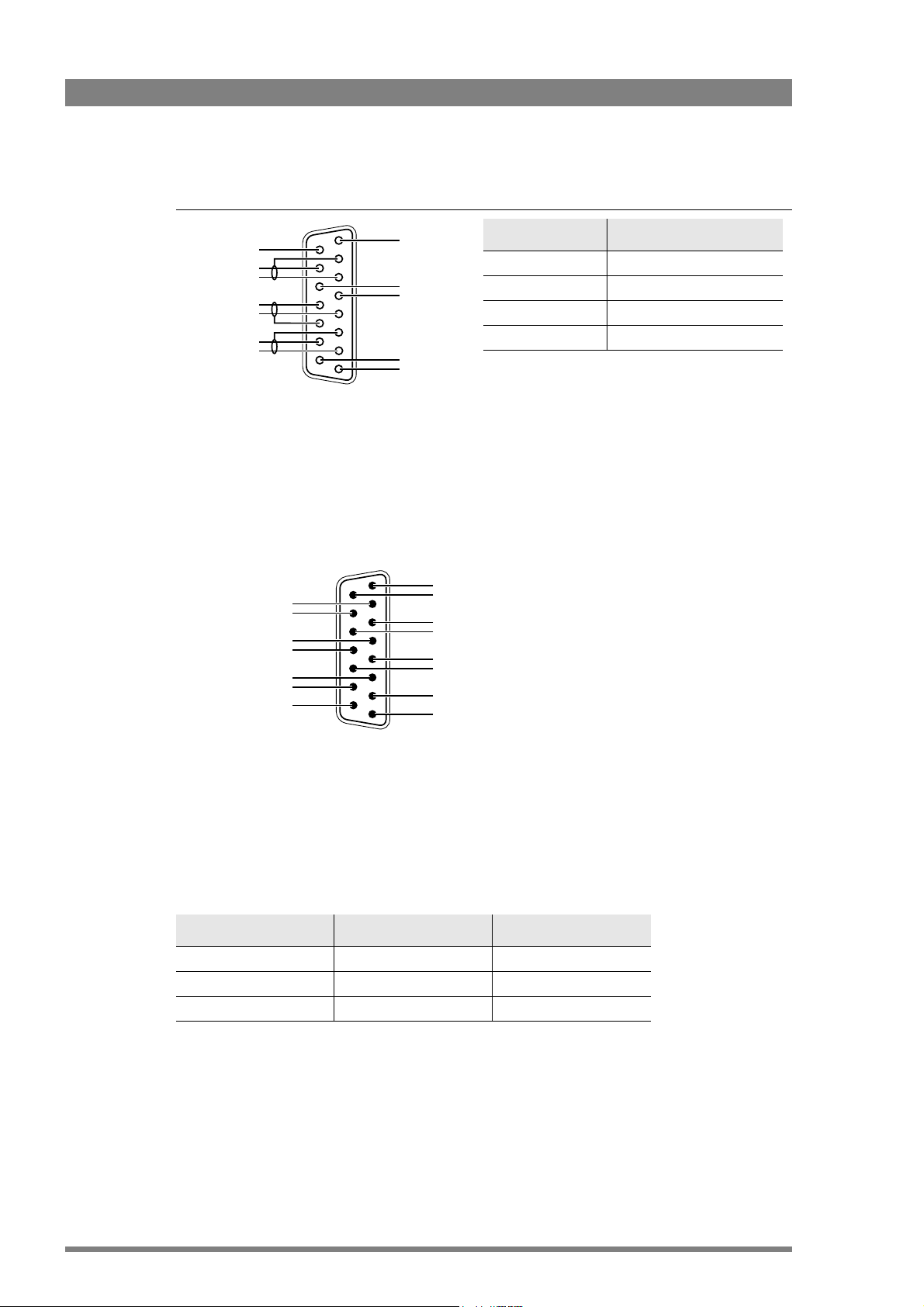
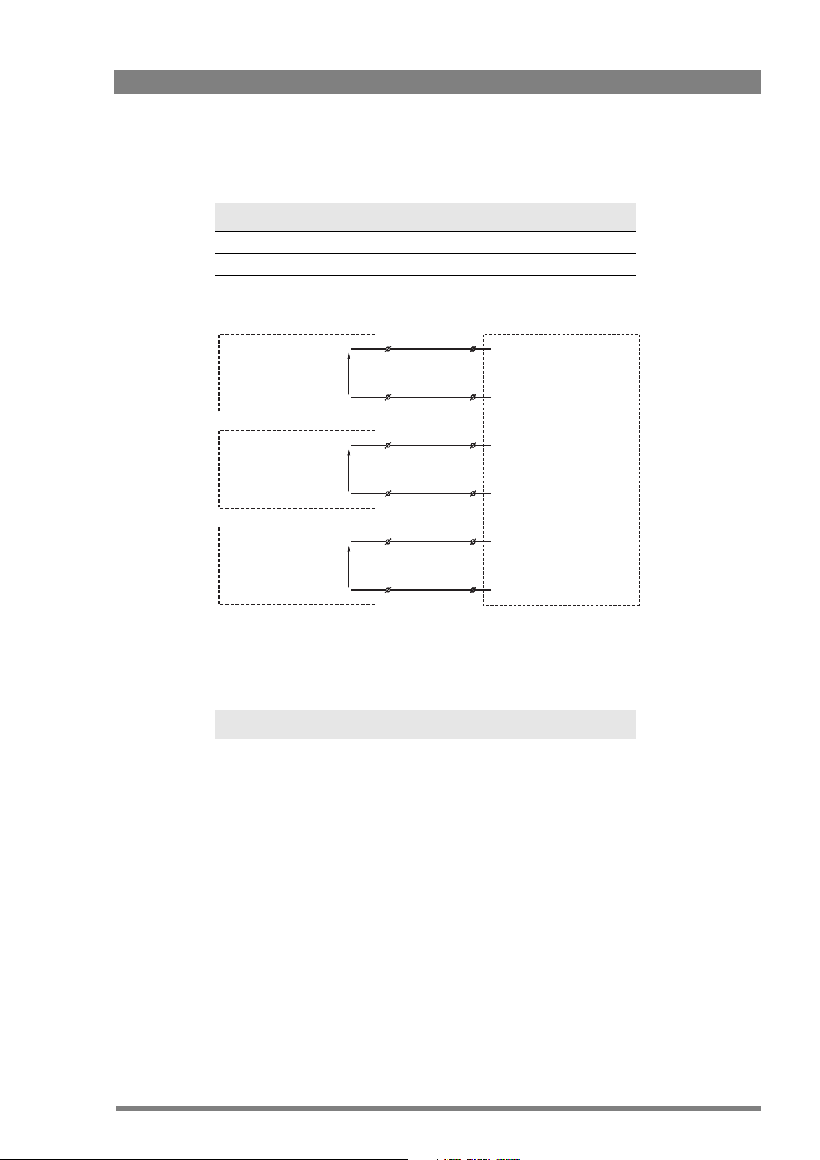
Four-wire systems
Function Valu e
Output signal level +6 or 0 dBu (RMS) selectable
Output impedance max. 50 symmetrical
Input signal level +6 or 0 dBu (RMS) selectable
Impedance min. 9 k symmetrical
-
+
-
+
Housing
Eng in/out
Prod in/out
Housing
Prog in ret
Prog in
Prod in ret
Prod in
Eng in ret
Eng in
Call out send
Call out return
On Air send
On Air return
Audio 1 level
Audio 2 level
GND
Preview out send
Preview out return
ISO in send
ISO in return
Call in send
Call in return
5 V
Housing
2.1.3 Studio signalling
Connect the studio signalling system to the rear of the base station. The wiring of the
signalling connector is shown below:
Chapter 2 - Base station
8
15
9
1
1
9
15
8
There are several connection methods for the ISO (On Air Yellow), On Air and Call signalling
functions: dry contact, common ground, voltage level and open circuit/voltage level.
A selection in the SYSTEM > SIGNALLING menu allows you to make the activity state of the
function (Active or Inactive) correspond to a particular input signal. There are two leads for each
connection - Send and Return.
Signalling function Send pin Return pin
ISO 3 11
On Air 4 12
Call 2 10
16 LDK 4410 + LDK 5420 3G Fiber Transmission System User’s Guide (v1.0)
Page 17
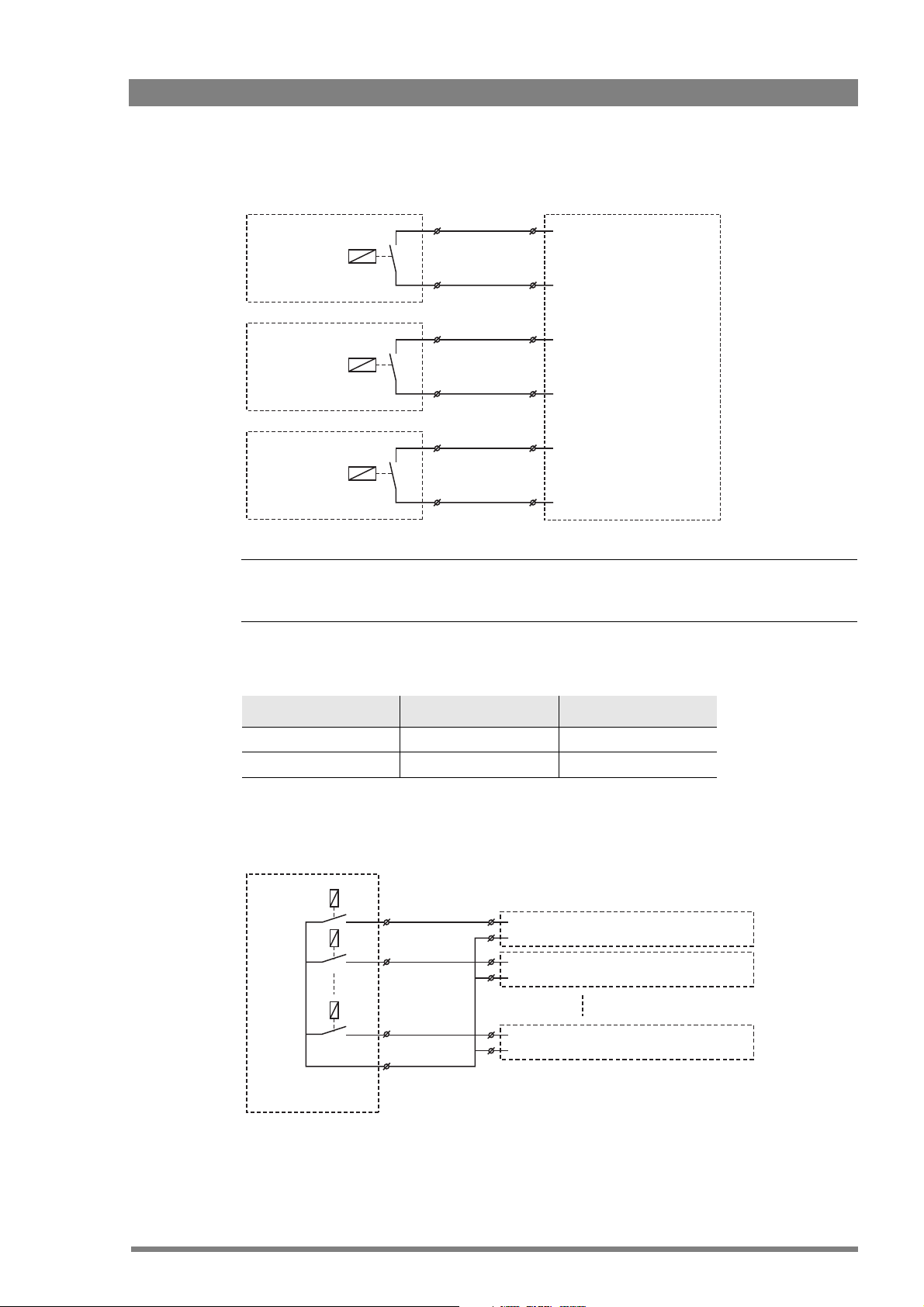
Dry contact
☞
Note
☞
Note
Chapter 2 - Base station
External ISO signalling
(dry contact)
External On-Air signalling
(dry contact)
External Call signalling
(dry contact)
ISO 1a
ISO 1b
On-Air (Tally) 1a
On-Air (Tally) 1b
Call 1a
Call 1b
ISO in ext. send (pin 3)
ISO in ext. return (pin 11)
On-Air in ext. (pin 4)
On-Air in ext. return (pin 12)
Call in ext. (pin 5)
Call in ext. return (pin 13)
A common return (not ground!) can be used for all three functions (ISO, On Air and Call)
If a contact is closed, the corresponding function is Active or Inactive, depending on the
selection the SYSTEM > SIGNALLING menu:
Menu setting Input is shorted: Input is open:
LH (low-high) Function is Active Function is Inactive
HL (high-low) Function is Inactive Function is Active
Dry contact with multiple base stations
This is an example of an On Air signalling with multiple base stations using a common contact.
On-Air (Tally) 1
On-Air (Tally) 2
On-Air (Tally) n
Common
External On-Air signalling
(common contact)
On-Air in ext. send (pin 4) Signalling connector
On-Air in ext. return (pin 12) Base Station 1
On-Air in ext. send (pin 4)
On-Air in ext. return (pin 12)
On-Air in ext. send (pin 4)
On-Air in ext. return (pin 12)
Signalling connector
Base Station 2
Signalling connector
Base Station n
LDK 4410 + LDK 5420 3G Fiber Transmission System User’s Guide (v1.0) 17
Page 18
Chapter 2 - Base station
☞
Note
☞
Note
☞
Note
☞
Note
Use either Send or Return only, but do not mix.
If a contact is closed, the corresponding function is Active or Inactive, depending on the
selection the SYSTEM > SIGNALLING menu:
Menu setting Input is shorted: Input is open:
LH (low-high) Function is Active Function is Inactive
HL (high-low) Function is Inactive Function is Active
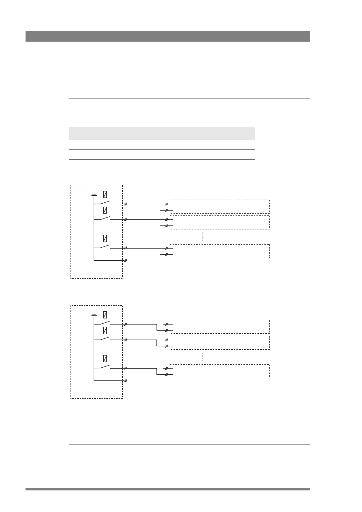
Common ground
External On-Air signalling
(common ground contact)
On-Air (Tally) 1
On-Air (Tally) 2
On-Air (Tally) n
On-Air (Tally) 1
On-Air (Tally) 2
On-Air (Tally) n
On-Air in ext. (pin 4) Signalling connector
On-Air in ext. return (pin 12) Base Station 1
On-Air in ext. (pin 4)
On-Air in ext. return (pin 12)
On-Air in ext. (pin 4)
On-Air in ext. return (pin 12)
On-Air in ext. (pin 4) Signalling connector
On-Air in ext. return (pin 12) Base Station 1
On-Air in ext. (pin 4)
On-Air in ext. return (pin 12)
On-Air in ext. (pin 4)
On-Air in ext. return (pin 12)
Signalling connector
Base Station 2
Signalling connector
Base Station n
Signalling connector
Base Station 2
Signalling connector
Base Station n
External On-Air signalling
(common ground contact)
Ensure that a reliable ground coupling exists between the control device ground and the base
station ground.
18 LDK 4410 + LDK 5420 3G Fiber Transmission System User’s Guide (v1.0)
Page 19
Chapter 2 - Base station
If a contact is closed, the corresponding function is Active or Inactive, depending on the
selection the SYSTEM > SIGNALLING menu:
Menu setting Input is shorted: Input is open:
LH (low-high) Function is Active Function is Inactive
HL (high-low) Function is Inactive Function is Active
Voltage level
0 .. 2.5 VDC
4 .. 24 VDC
0 .. 2.5 VDC
4 .. 24 VDC
0 .. 2.5 VDC
4 .. 24 VDC
+
-
+
-
+
-
ISO 1a
ISO 1b
On-Air (Tally) 1a
On-Air (Tally) 1b
Call 1a
Call 1b
ISO in ext. send (pin 3)
ISO in ext. return (pin 11)
On-Air in ext. send (pin 4)
On-Air in ext. return (pin 12)
Call in ext. send (pin 5)
Call in ext. return (pin 13)
Apply a DC voltage to the inputs (respect polarity). If the voltage is low (0 to 2.5 V), the function
is Active (or Inactive). If the voltage is high (4 to 24 V) the function is Inactive (or Active). The
function state depends on the selection the SYSTEM > SIGNALLING menu:
Menu setting Input is 0 to 2.5V: Input is 4 to 24V:
LH (low-high) Function is Active Function is Inactive
HL (high-low) Function is Inactive Function is Active
LDK 4410 + LDK 5420 3G Fiber Transmission System User’s Guide (v1.0) 19
Page 20
Open circuit/Voltage level
Chapter 2 - Base station
Open/
4..24 VDC
Open/
4..24 VDC
Open/
4..24 VDC
ISO 1a
ISO 1b
On-Air (Tally) 1a
On-Air (Tally) 1b
Call 1a
Call 1b
ISO in ext. send (pin 3)
ISO in ext. return (pin 11)
On-Air in ext. send (pin 4)
On-Air in ext. return (pin 12)
Call in ext. send (pin 5)
Call in ext. return (pin 13)
Leave the circuit open or apply a DC voltage to the inputs (respect polarity). If the circuit is
open, the function is Active (or Inactive). If the voltage is high (4 to 24 V) the function is Inactive
(or Active). The function state depends on the selection the SYSTEM > SIGNALLING menu:
Menu setting Input is open: Input is 4 to 24V:
OH (open-high) Function is Active Function is Inactive
HO (high-open) Function is Inactive Function is Active
20 LDK 4410 + LDK 5420 3G Fiber Transmission System User’s Guide (v1.0)
Page 21
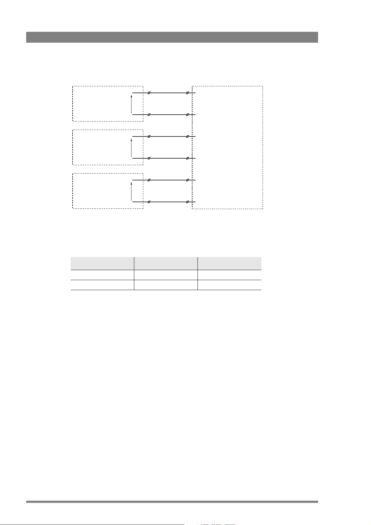
2.1.4 External audio level control
Audio 1 level (pin 6)
Audio 2 level (pin 14)
Mic/Line Mic/5 V (pin 7)
GND (pin 15)
1k
1k
1k
1k
1k
1k
1k
1k
+4.3V
+3.7V
+3.1V
+2.5V
+1.9V
+1.3V
+0.7V
0V
-22/+12dBu
-28/+4dBu
-34/-2dBu
-40/-8dBu
-46/-14dBu
-52/-20dBu
-58/-26dBu
-64/-32dBu
5
1
9
6
Private data
in
Private data
out
Function Val ue
Bitrate max. 100 kbit/s
Output level (high) > 4 V
Output level (low) < 4 V
Output impedance 250
Input level (high) > 2 V (max. 12 V)
Input level (low) < 2 V
Input impedance > 4.7 k
The camera audio level for channel 1 and 2 can be externally controlled by the base station. In
the camera menu, go to the INSTALL
On the OCP, push the SETUP button and choose the Cam(era) submenu. Use the NEXT button
to scroll to the REM AUDIO menu and select Rem. Apply a DC voltage to pins 6 and 14 of the
signalling connector to control the levels of audio channels 1 and 2 respectively, as shown in
the figure below:
Chapter 2 - Base station
> AUDIO > AUDIO GAIN MODE item and select Ext.
The actual audio level depends on the setting of the selection switches at the back panel of the
camera adapter. When Mic is selected, the maximum gain level is -64 dBu, while maximum
Line level is -32 dBu.
2.1.5 Private data
Private data channels can be used for sending serial data via the transmission cable. For
example, electronic scriptboard or character data for a video display unit or pan and tilt data can
be transmitted to the camera.
LDK 4410 + LDK 5420 3G Fiber Transmission System User’s Guide (v1.0) 21
Remember that the propagation-delay times are different for different cable lengths, especially
if a return signal is involved. At maximum lengths the total delay is at least 25 μs and can be
more than 30 μs depending on the type of cable. The duty cycle difference between input and
output is max. 5%.
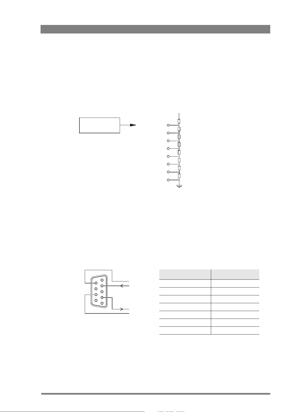
Page 22
2.2 Base station menu
☞
Note
☞
Note
Open
clasp
Open
clasp
Front
cover
Segment
display
Rotary/push
button
The base station can be set up using either:
• The rotary/push button on the data board inside the base station or
• An Operation Control Panel (OCP) connected to the base station.
2.2.1 Using the rotary/push button
Push the two clasps at the bottom of the front cover upward and remove the front cover to
access the inside:
Camera
On Air Base
Communication
Chapter 2 - Base station
Power On
Test Connected
Station
Mains
Ready
Camera
Locate the rotary/push button on the data board at the left. Rock the button to the left or right
to select the required item. The segment display shows the code of the selected item.
When accessed from the base station, the user level is set to Install.
There are three items that can be selected:
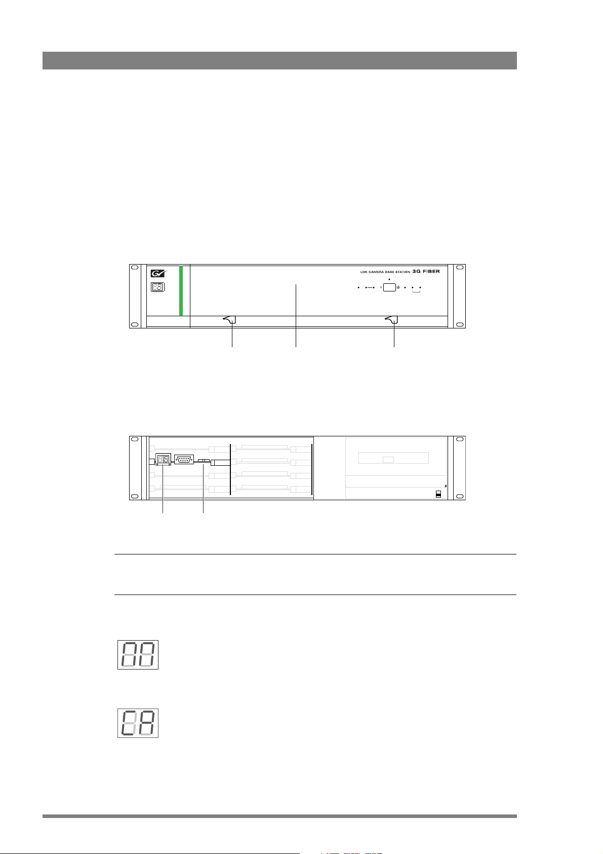
Base station menu
When “NN” is displayed, push the rotary/push button twice to enter the base
station menu. The rotary/push button can be used to navigate through the menu.
The menu appears on the Monitoring and CVBS + Text outputs of the base station.
Camera number
When “CA” is displayed, push the rotary/push button to enter the selection mode.
Rock the button to the left or right to select an available camera number. Push the
rotary/push button again to confirm the new camera number. The base station automatically
resets and the new camera number is shown in the display.
22 LDK 4410 + LDK 5420 3G Fiber Transmission System User’s Guide (v1.0)
Page 23
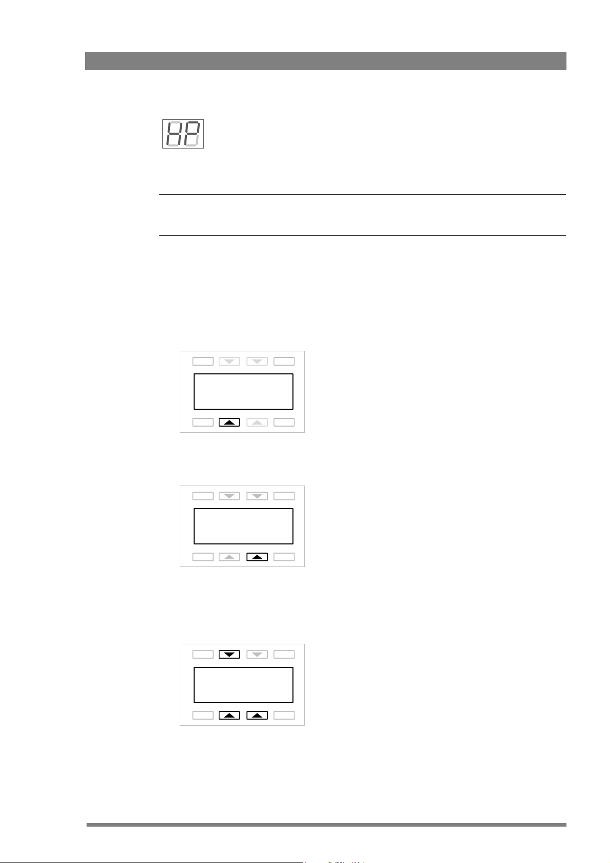
continue to rock the button, the shift change occurs in bigger steps. Push the rotary/push
☞
Note
☞
Note
button again to leave the H-Phase adjustment mode.
This item is only available when a reference signal is present.
2.2.2 Using the OCP
The OCP can be used access the base station menu instead of the rotary/push button.
1. Push the Setup button on the OCP to open the menu.
2. Push the selection button to choose the BS menu.
Chapter 2 - Base station
H-Phase adjustment
When “HP” is displayed, push the rotary/push button to enter the H-Phase
adjustment mode. Rock the button to the left or right to shift the H-Phase. If you
EXIT
Diag OCP
BS Cam
PREV
TOGGLE
NEXT
3. Push the selection button enter the Menu
EXIT
Menu
PREV
TOGGLE
NEXT
4. The menu appears on the Monitoring and CVBS + Text outputs of the base station. Use
the appropriate selection buttons to navigate the menu. You can also use the rotary contol
on the OCP to move up or down through the menu.
EXIT
TOGGLE
UP
DOWN SELECT
PREV
LDK 4410 + LDK 5420 3G Fiber Transmission System User’s Guide (v1.0) 23
NEXT
Page 24
☞
Note
☞
Note
When accessed from the OCP, the user level is set to Operator.
2.2.3 Menu navigation
The base station menu is used for configuring the base station. As there are a large number of
functions and set-up options available, it may require some time to become familiar with them
all. The menu video signal is available on the Monitoring and CVBS+Text outputs.
Entering the menu
Use the rotary/push button at the front of the base station or the Operational Control Panel to
access the base station menu. The functions of the base station are grouped into menus and
sub-menus. When accessed, the main menu appears on the monitor.
Chapter 2 - Base station
MENU OFF
Video
Monitoring
Audio/Intercom
SDTV
System
Root
Files
Diagnostics
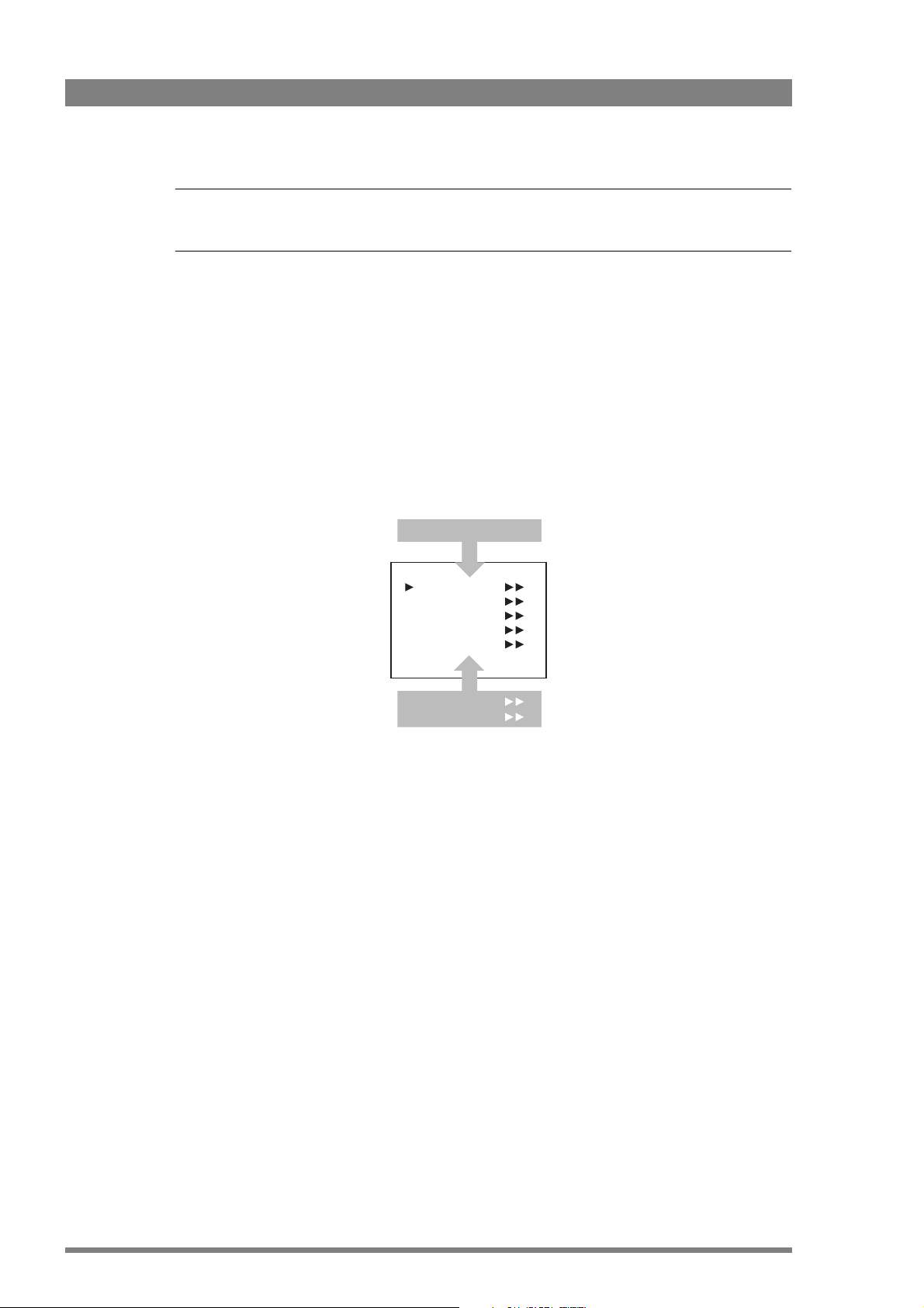
The main menu screen shows five items and the name of the menu. One or more item can be
hidden but become visible when you scroll down. A cursor shows your position in the menu.
The navigation buttons (rotary/push button or OCP buttons) move the cursor up and down.
Finding your way
Use navigation buttons to move the cursor through the menu items. If a double arrow (>>) is
visible, then pressing the rotary/push button or the SELECT button brings you one level lower
in the menu system. Only five items are visible in each menu. Scroll up or down to see more
items.
When you first enter a menu (other than the main menu) the cursor is positioned next to the
first item. The TOP and PREVIOUS entries are not immediately visible but are located above
the first item. Use the control to scroll up to them.
24 LDK 4410 + LDK 5420 3G Fiber Transmission System User’s Guide (v1.0)
Page 25

Chapter 2 - Base station
Camera Number
Camera Power
MCP Available
Yellow On Air
Timing
Clock
Video Mode
Teleprompter
TOP
PREVIOUS
System
1
On
Yes
Std
10i59
Off
• Select TOP to bring you back to the MAIN menu.
• Select PREVIOUS to go back to the menu that you were in before the current one.
The SYSTEM menu above shows the items displayed when you first enter the menu and the
other items that are available by scrolling up or down.
Leaving the menu
If you are deep within the menu structure, follow these steps to leave:
• If necessary move the cursor to the left most column.
• Scroll upwards until the cursor points to TOP (this is the main menu).
• Press the rotary/push button or the SELECT button on the OCP. The cursor now points to
the Menu off item of the MAIN menu.
• Press the rotary/push button or the SELECT button on the OCP to leave the system menu.
This is the recommended way of leaving the system menu. The menu system disappears after
a few seconds when you stop navigating. This delay can be set in the MONITORING > MENU
menu. However, when you enter the system menu again you enter at the last position of the
cursor and not at the top of main menu. To prevent confusion the next time you enter the
system menu, it is advisable to leave the system menu by returning to the main menu (TOP)
and selecting MENU OFF.
Making changes
To find out where to change a function, consult “Base station menu” on page 47to find out
under which menu group or subgroup the function is located. If the cursor points to an item
(and there are no double arrows to indicate a sub-menu) then the item pointed to has a value.
The value can be:
• a toggle value (only two values)
• a list value (more than two values)
• an analogue value (variable from 00 to 99)
• or unavailable (---).
If the value is unavailable it cannot be changed. This is indicated by three dashes (---). This can
LDK 4410 + LDK 5420 3G Fiber Transmission System User’s Guide (v1.0) 25
occur, for example, when a function is switched off. The analogue values associated with that
function are then unavailable. If there are only two values associated with the function, then
Page 26

Chapter 2 - Base station
☞
Note
☞
Note
pressing the rotary/push button toggles between these two values. If a value is displayed next
to a function that is one of several possible values, then pressing the rotary/push button or the
SELECT button on the OCP places the cursor in a list menu indicating the value currently
selected. Use the rotary/push button or the SELECT button on the OCP to point to a new
value.
Press the rotary/push button or the SELECT button on the OCP to return the cursor to the
function list. If an analogue value is displayed next to a function name, then pressing the
rotary/push button or the SELECT button on the OCP places the cursor in front of the value and
the navigation control is used to change the analogue value. Press the rotary/push button or
the SELECT button on the OCP to return the cursor to the function list.
Using Recall File to undo changes
If you make changes to the settings in the menu and you decide not to keep them, use the
Recall File function to recall a standard or stored set of values for the parameters. These files
are available in the FILES menu.
User levels
The menu items are divided into two user levels. The operator level (O) is default accessible.
Menu items with user level Install (I) are only accessible if the menu level is set to Install. To
enter the Install level proceed as follows:
1. Enter the menu.
2. Navigate to the MONITORING > MENU > MENU LEVEL item.
3. Set the Menu level to Inst.
The purpose of the user levels is to restrict the set of functions which can be changed by
whoever is using the base station. In this way a the danger of the operator accidentally
changing critical functions while shooting is reduced.
When accessed from the base station, the user level is set to Install while the user level is set
to Operator when accessed from the OCP.
26 LDK 4410 + LDK 5420 3G Fiber Transmission System User’s Guide (v1.0)
Page 27

2.3 Intercom setup
Tip
✎
The studio camera systems offer extensive intercom facilities between cameraman, tracker
(floor man), base station and studio. To help you set up and operate the intercom system, the
following controls are available:
• Base station menu system
• Camera head menu system
• Camera adapter rear panel
• Camera head switches
When setting up a system it is usually more convenient to use an OCP to select your
preferences in both the base station and camera head menu systems.
2.3.1 Studio interface setup
A four-wire or a two-wire studio system can be connected to the base station. In the
AUDIO > INTERCOM menu, select the Wire Mode for engineering (ENG), production (PROD)
and programming (PROG) channels. By default these values are set to four-wire.
Chapter 2 - Base station
Isolate
The isolate function completely disconnects the base station intercom from the studio system.
The function can be switched locally or remotely via the OCP.
Levels
In the four-wire mode the menu gives you a choice of either a 0 dBu or a +6 dBu signal level. In
the two-wire mode this level is set to 0 dBu.
• Set the input and output intercom levels for the PROD and ENG channels. The range is 0
to 99; default is 50.
• Set the input level for the PROG channel.
• Set the levels for the sidetone in a two-wire system in this menu.
LDK 4410 + LDK 5420 3G Fiber Transmission System User’s Guide (v1.0) 27
Page 28

2.4 Reference and timing set up
Tip
✎
Camera
Base station
processing
HD tri-level reference or
SD black burst reference
Scaler
HD > SD
HD output
SD output
HD output with HD
tri-level reference
HD output with SD
black burst reference
HD tri-level reference
H-phase range
H-phase range
SD black burst reference
2.4.1 Basic signal processing
The base station can be synchronized using HD tri-level or SD black burst references. Both
references can be adjusted to match the video output signals. This is an overview of the base
station output signal paths:
Chapter 2 - Base station
The default settings for the base station reference signals are:
• The first reference is HD tri-level: the outputs are in time with the HD tri-level
synchronization.
• The second reference is SD black burst: the outputs are in time with the SD black burst.
2.4.2 Adjustment procedure for HD timing
t
0
t
0
28 LDK 4410 + LDK 5420 3G Fiber Transmission System User’s Guide (v1.0)
When HD tri-level reference is used, the HD output is in sync with the HD tri-level reference. A
timing offset can be set with the SYSTEM > TIMING > H PHASE COARSE and H PHASE FINE
items of the base station menu.
Page 29

2.4.3 Adjustment procedure for SD timing
☞
Note
☞
Note
The SD output signal can be delayed using the following procedure:
1. Enter the base station menu in service mode:
MONITORING > MENU > MENU LEVEL > INST > SERVICEMODE > EXEC > YES
2. After factory delivery there is a fixed minimum delay between HD and SD outputs:
SDTV > TIMING > COMP
3. Set the SDTV timing to variable:
SDTV > TIMING > VAR
4. Adjust the SD output delay using the following items:
SDTV > TIMING > SYNC SHIFT PIXELS and SHIFT LINES
The adjustment must be carried out for each video mode. The last setting for each mode is
memorized.
The CVBS viewing output is a non-standard output and the SD output delay adjustment does
not apply to this output.
HD-trilevel sync does not contain 4-field (NTSC) or 8-field (PAL) sequence information and
therefore will be random. If this is required black burst reference should be used.
Chapter 2 - Base station
LDK 4410 + LDK 5420 3G Fiber Transmission System User’s Guide (v1.0) 29
Page 30

Chapter 2 - Base station
30 LDK 4410 + LDK 5420 3G Fiber Transmission System User’s Guide (v1.0)
Page 31

Chapter 3
Caution
Camera adapter
3.1 Mounting
Chapter 3 - Camera adapter
3.1.1 General
In general, a camera system is delivered with the camera head and camera adapter already
attached. However, the dockable concept enables switching the transmission system by
exchanging the camera adapter (and base station).
Be extremely careful with the connectors between the camera head and the adapter. Do not
allow the metal guide pins to damage the pins of the connector.
Follow the indicated steps in the exact order given below. Tightening or loosening the screws
in the wrong order could result in mechanical damage to the camera and adapter.
Exchange the adapter in a safe area, preferably indoors. Make sure your working area is clean
and dust free.
3.1.2 Detaching
To detach the adapter from the camera head proceed as follows:
1. Unscrew the vertical screw (5) in the handgrip of the camera head.
2. Unscrew the two horizontal screws (4) at the front of the camera head.
3. Unscrew the two horizontal screws (3) at the top of the camera head.
4. Carefully disconnect the adapter from the camera head.
LDK 4410 + LDK 5420 3G Fiber Transmission System User’s Guide (v1.0) 31
Page 32

3.1.3 Attaching
Tip
✎
5
1
4
3
2
1
To attach the adapter to the camera head proceed as follows:
1. Fit the guide pin at the top rear of the camera head and the guide pins on either side of
2. First, tighten the two horizontal screws (3) on the top of the camera head.
3. Next, tighten the two horizontal screws (4) at the front of the camera head.
4. Lastly, tighten the vertical screw (5) in the handgrip of the camera head.
Chapter 3 - Camera adapter
the camera connector into the corresponding slots (1 and 2) of the adapter.
3.1.4 Adjusting the shoulder pad
To change the position the shoulder pad press and hold lever (1). The shoulder pad can now be
moved backwards and forwards along the axis of the camera.
Adjust the shoulder pad when all units are mounted to get the best balanced shoulder position.
32 LDK 4410 + LDK 5420 3G Fiber Transmission System User’s Guide (v1.0)
Page 33

3.2 Controls and indicators
VF
HD-SDI (B)/VF
HD-SDI (A)
+48V
+48V
Mic.
Mic.
Line
Line
An.
VF
AES
In
Front
Rear
Mic 2
Call
Mic 1
Eng
Off
Prod
Front
Rear
Ext1
Ext2
Loc
Mix
Ext
Eng Progr Prod
VF
Power on
Script Light
Breaker
12V 1.5A max.
11-17V 5A
Intercom
routing switch
Headset production
volume control selection
Headset volume
controls
Call button
Microphone phantom
power switch
Powe r On
indicator
Circuit breaker
button
Viewfinder display
signal selection
Audio microphone
switches
VF connector signal
selection switch
(see “VF connector (+
digital audio)” on
page 72 for more
information about this
switch)
Microphone phantom
power switch
Power output
connector
Power input
connector
3.2.1 Overview
Chapter 3 - Camera adapter
3.2.2 Power
LDK 4410 + LDK 5420 3G Fiber Transmission System User’s Guide (v1.0) 33
The power supply for the camera and its adapter is normally supplied via the transmission
cable coming from the base station. The Power On indicator lights when power is supplied and
the camera power switch is set to the on position .
When power is supplied via the transmission cable, an output power socket supplies 12 VDC,
1.5 A maximum for powering accessories.
It is also possible to operate the camera without a transmission cable by supplying a 12 VDC
supply to the DC input socket. The BATT indicator in the viewfinder lights if the camera supply
voltage is less than 11.5 VDC when using an external supply.
If excessive current flows in the camera or adapter, the circuit breaker trips and shuts off
power to all the units. If this happens check the units for faults and if necessary take corrective
actions before pressing the circuit breaker button to reset the power.
Page 34

3.2.3 Selecting monitoring signals
External signal
selection switch
Viewfinder display
switch
Viewfinder display signal
The viewfinder can display local (from camera) or external (from base station) video. Two
switches at the back of the adapter determine the signal that is displayed in the viewfinder.
Eng
Off
Prod
Ext1
Ext2
The viewfinder display switch determines how the local and external signals are displayed in
the viewfinder:
– Loc: displays the local signal (Y only) in the viewfinder,
Chapter 3 - Camera adapter
Front
Rear
VF
Loc
Mix
Ext
– Mix: displays a mix (-½A + ½B) of the local (Y only) and external signal or
– Ext: displays the external signal in the viewfinder
When the viewfinder display switch is set to Mix or Ext, the external signal selection switch
determines which external (return) video signal from the base station is displayed in the
viewfinder:
– Ext1: displays external signal Ext1 or
– Ext2: displays external signal Ext2 or Ext3.
Go to the INSTALL > BUTTONS > EXT2 ASSIGN menu and select Ext3 to use the Ext3 channel
instead of Ext2.
3.2.4 Using audio
Analog audio channels
Set the gain levels (-22 to -64 dB) for these channels in the AUDIO section of the INSTALL
menu. A high-pass filter for each channel can also be switched on via this menu.
The channel 1 input socket selection switch selects either:
• the socket at the front-right of the camera, or
• the Mic 1 audio channel 1 connector at the rear of the adapter
as the input for channel 1.
The rear input level switch selects either a line level input or a microphone level input for the
channel 1 rear connector. The line level input sensitivity is 32 dB lower than the microphone
input sensitivity.
34 LDK 4410 + LDK 5420 3G Fiber Transmission System User’s Guide (v1.0)
Page 35

Chapter 3 - Camera adapter
Audio channel 1
connector
Channel 1 phantom
power switch
Audio channel 2
connector
Channel 2 phantom
power switch
Channel 1 input socket
selection switch
Rear input level selection
switch (channel1)
Channel 2 input level
selection switch
VF connector signal
selection switch
The switch under the Mic 1 socket selects a phantom power supply (48 V) for the rear socket.
Phantom power (48 V) is always present on the front-right microphone socket.
Front
Rear
Mic 1
Line
Mic.
Mic.
Line
An.
AES
VF
In
+48V
Mic 2
+48V
The channel 2 rear input level switch selects either a line level input or a microphone level input
for the channel 2 rear connector (Mic 2). The switch under the Mic 2 socket selects a phantom
power supply (+48 V) for the rear socket.
Audio channels 1 and 2 are available on the audio output 1 and 2 connectors (XLR-3) at the
base station and as digital outputs on the digital audio output (1+2) connector (BNC) at the
base station. They are also embedded as audio channels 1 and 2 in the HD-SDI video signal.
LDK 4410 + LDK 5420 3G Fiber Transmission System User’s Guide (v1.0) 35
Digital audio channels
Two AES/EBU digital audio channels are available. Set the VF connector signal selection switch
to AES In and connect a digital audio source to the VF connector.
Digital audio channels 3 and 4 are available on the digital audio output (3+4) connector (BNC)
at the base station and as embedded audio channels 3 and 4 in the HD-SDI video signal.
Page 36

3.2.5 Intercom
Production channel volume
control (only active when the
adjacent control switch is set
to Rear)
Program channel
volume control
Engineering channel
volume control
Production intercom
volume control switch
Intercom microphone
routing switch
Three intercom channels – production (Prod), program (Prog) and engineering (Eng) – are sent
from the base station to the camera operator's headset. The camera operator's intercom
microphone signal is sent back to the base station. Routing and volume controls for the
intercom can be found on the back of the adapter:
Eng
Prod
Ext1
Ext2
Chapter 3 - Camera adapter
Front
Off
Rear
VF
Loc
Mix
Ext
Eng Progr Prod
Production intercom volume control switch
Use this 2-position switch to control the volume of the production signal in the intercom either
at the front of the camera or at the rear of the adapter.
Intercom microphone routing switch
This 3-position switch routes the camera operator's intercom microphone signal to Engineering
(Eng position, latched) or production (Prod position, momentary), or turns it off (mid-position).
The VTR Start button at the front of the camera or the VTR button on the lens can be assigned
to send the intercom signal to Production or Engineering, regardless of the position of this
switch. Go to the INSTALL > BUTTONS > VTR START item and select PROD or ENG.
Intercom headset volume controls
• Prod - adjusts the volume of the production signal to the camera headset when selection
switch is in the Rear position.
• Prog - adjusts the volume of the programme signal to the camera headset.
• Eng - adjusts the volume of the engineering intercom signal to the camera headset.
The INTERCOM section of the INSTALL menu contains various settings for all these channels.
Signals for left and right headset muffs and sidetone levels can be selected. Intercom
microphone amplification levels, phantom power supply and microphone on/off switches are
also available in this menu.
Tracker intercom
A tracker can connect a headset to the side of the adapter to receive the intercom channels
from the base station and the camera operator's microphone signal. The tracker's microphone
signal is passed to the camera operator and to the base station.
36 LDK 4410 + LDK 5420 3G Fiber Transmission System User’s Guide (v1.0)
Page 37

3.2.6 Communication
Call button
Press this momentary button to send a signal to the control panels calling for attention. The
ND/RE indicator in the viewfinder shows when a call signal is sent or received.
The call button can also be used to playback a voice mail message that has been recorded in
the base station. Press once to start playback; press again to stop.
Data channel
The Aux connector on the side of the adapter provides analog control signals and allows for the
connection of a two-way private data channel between camera and base station.
Tracker tally signal
The tracker connector on the side of the adapter, as well as providing full intercom facilities for
the dolly or crane driver, also carries a tally signal and a 12 VDC power supply. This allows an
external On Air lamp to be used.
Chapter 3 - Camera adapter
LDK 4410 + LDK 5420 3G Fiber Transmission System User’s Guide (v1.0) 37
Page 38

Chapter 3 - Camera adapter
38 LDK 4410 + LDK 5420 3G Fiber Transmission System User’s Guide (v1.0)
Page 39

Chapter 4
On Air and
ISO
indicators
Base Station
Ready
indicator
Camera
communication
indicator
Camera Test
and Connected
indicators
Segment
display
Power
on
indicator
Transmission
4.1 Base station indicators
During setup and operation transmission can be monitored on the base station. There are
several display and indicators that provide information about operational functions.
Chapter 4 - Transmission
Power On
Camera
On Air Base
Communication
Test Connected
Station
Mains
Ready
Camera
Segment display
In normal operation the segment display shows the logical number of the camera connected to
the base station. When the base station menu is accessed the display shows menu items.
Power On indicator
This green indicator lights when the base station is switched on.
Camera Communication indicator
This green indicator lights when communication between camera and base station is
established and working correctly.
LDK 4410 + LDK 5420 3G Fiber Transmission System User’s Guide (v1.0) 39
Page 40

Chapter 4 - Transmission
On Air and ISO indicators
The red On Air indicator lights when the connected camera is switched On Air. The yellow ISO
indicator lights when the connected camera is in ISO mode.
Base station Ready indicator
This green indicator lights when the base station is operationally ready.
Camera Test indicator
This bi-color indicator lights red or yellow to indicate the camera and transmission status. Refer
to the table below for an explanation.
Camera Connected indicator
This green indicator lights when the camera is connected (and camera power is not switched
off by the OCP, MCP or base station menu).
Camera
Connected ind.
Green flashing Off Transmission cable is connected to camera.
Green Off Transmission cable is connected to camera and camera is
Off Red flashing Transmission cable open.
Off Red Transmission cable error: shortcircuit or wrong power system.
Off Yellow Camera power is switched off by a control panel or from a menu.
Off Yellow Power shutdown sequence in progress
Off On Selftests are running
Camera
Test indicator
Description or fault condition
powered.
1)
Other indications of these situations:
1)
OCP: Cable LED flashes red; MCP: DIAGNOSE > - OPEN; Base station menu:
DIAGNOSTICS > COMMUNICATIONS > CAMERA CONNECTED - NO
2)
OCP: Cable LED red (continuously); MCP: DIAGNOSE > - SHORT; Base station menu:
DIAGNOSTICS > BOARD DIAGNOSTICS > POWER BOARD > STATUS
2)
40 LDK 4410 + LDK 5420 3G Fiber Transmission System User’s Guide (v1.0)
Page 41

4.2 Transmission diagnostics
Base station to camera signal
quality indication.
Camera to base station signal
quality indication.
Camera to base station cable
quality indication.
Base station to camera cable
quality indication.
OK
|
NoSignal
Init Fail
Sync Lock
Ext. Ref. Avail.
Burst Lock
4.2.1 Monitoring transmission
A connected Operational Control Panel can be used to monitor the transmission between
camera and base station.
Chapter 4 - Transmission
EXIT
BS>C Cable
Signal OK
C>BS Cable
Signal
PREV NEXT
TOGGLE
|
ERROR
NoSignal
Indication Description
Cable or signal quality is OK
|
ERROR
Cable or signal quality is below optimum, transmission is still in operation. The
quality level can vary between 6 (high) and 0 (low) units.
Cable or signal quality is poor. Check cables or transmission.
Cable error: check cable for interruptions, broken or dirty optical connections.
No signal is received: Check transmission.
4.2.2 Sync/encoder HD board diagnostics
The LEDs on the sync/encoder HD board show the status of the board and the signal locking
as follows:
Indicator Description
Init. Fail Lights (red) when a configuration or initialisation error occurs or when the bus
Sync Lock Lights (green) when horizontal and vertical lock are OK.
LDK 4410 + LDK 5420 3G Fiber Transmission System User’s Guide (v1.0) 41
clock or video synchronization pulses are missing.
Page 42

Indicator Description
Digital output
board
Data
board
Sync/encoder HD
board
Transmission
board
HQ SDTV
board (option)
Powe r
unit
Audio intercom
board
Ext. Ref. Avail. Lights (green) when an external synchronization signal is present.
Burst Lock Lights (green) when the subcarrier/H-phase lock is OK.
4.3 Board locations
4.3.1 Base station board locations
Chapter 4 - Transmission
42 LDK 4410 + LDK 5420 3G Fiber Transmission System User’s Guide (v1.0)
Page 43

4.3.2 Camera adapter board locations
Caution
Caution
Cooling
fan
Transmission
Fiber
board
Audio
intercom
board
Back
panel
Powe r
convertor
board
Powe r
module
HS
output
board
6
4
Chapter 4 - Transmission
89
4.4 Replacements
4.4.1 Replacing base station fuses
Switch off the base station and disconnect power cables before proceeding.
Use only fuses of the type and rating specified. Always replace both fuses at the same time.
The base station is equipped with 2x 8 AT type 250 V fuses . They are located in the mains
entry of the power supply unit at the back of the base station. Follow these steps to replace
the fuses:
LDK 4410 + LDK 5420 3G Fiber Transmission System User’s Guide (v1.0) 43
Page 44

Chapter 4 - Transmission
Insert small
screwdriver here
to open clip
Insert small
screwdriver here
to open clip
1. Insert a very small screwdriver into the hole at the left side and then at the right side of
the fuseholder to unclip both side of the fuseholder.
2. Extract the fuseholder from the mains entry by pulling of the small clip at the bottom of
the fuseholder.
3. Replace both fuses.
4. Insert the fuseholder until it clicks into place.
5. Connect the power supply for the base station to the IEC connector at the rear.
44 LDK 4410 + LDK 5420 3G Fiber Transmission System User’s Guide (v1.0)
Page 45

4.4.2 Replacing base station power supply unit
To remove the power unit from the base station, proceed as follows:
1. Make sure that the base station is switched off and disconnected from the mains.
2. Remove the screw at the rear of the power unit.
3. Push the two clasps at the bottom of the front cover to the left and remove the front
cover.
4. Grasp the metal horizontal bar and at the same time tilt the lever (indicated by the arrow
below) and pull out the power unit.
Chapter 4 - Transmission
PULL
LIFT
To reinstall the power unit into the base station, proceed as follows:
1. Slide the power unit into the guides and tilt the lever at the bottom right side of the power
unit.
2. Push in the power unit and release the lever. Make sure that the power unit is correctly
locked.
3. Tighten the screw at the rear of the power unit. Replace the front cover and click it into
place.
LDK 4410 + LDK 5420 3G Fiber Transmission System User’s Guide (v1.0) 45
Page 46

4.4.3 Replacing base station air filter
Dust filter
(attached to the
support)
The air filter of the base station is located inside the side panel of the casing. When the air filter
is dirty, it needs to be replaced. Contact your local Grass Valley representative to purchase a
replacement air filter. Follow the steps below to replace the filter:
1. Remove four screws from the left side panel.
Chapter 4 - Transmission
2. Pull out the bracket from the base station casing. The air filter is attached to the bracket.
3. Unhook and remove the filter.
4. Attach a clean air filter to the bracket.
5. Slide the bracket together with the filter back into the base station.
6. Fix the support with four screws.
46 LDK 4410 + LDK 5420 3G Fiber Transmission System User’s Guide (v1.0)
Page 47

Chapter 5
Menus
5.1 Base station menu
The structure of the main menus and their submenus are shown on the following pages. The
first column shows the user level: Install (“I”) or Operator (“O”). You only see menu functions
whose user level is equal to or less than the user level set on your unit. Where appropriate, the
default value of the function in the standard factory file is shown after the function.
All items in the table are visible at the install user level. However, if an item is not relevant it is
not shown.
The Oper in the Level column indicates that this item is visible at the Operator user level; the
Install indicates that this item is visible at the Install user level.
The Scene in the File column indicates that the value of this item is stored in the Scene file; the
Sys indicates that the value of this item is stored in the System file; the Oper indicates that the
value of this item is stored in the Operator file.
In the Values column, the default values of the item are shown in bold.
Chapter 5 - Menus
5.1.1 Top level
Menu Description
Video Contains those functions which affect the picture quality.
Monitoring Contains those functions which determine how items in the video monitor are displayed.
Audio/Intercom Contains those functions which control various aspects of audio and intercom.
SDTV Settings related to the SDTV outputs of the base station (only available when the optional
System Contains functions that are used to set up the general configuration and for carrying out
Files This menu allows values to be stored in system and operator files, and allows these files to
Diagnostics is designed to provide information on the current status of the base station.
LDK 4531/30 High Quality SD board is installed).
adjustments and calibrations of the base station.
be recalled as required.
LDK 4410 + LDK 5420 3G Fiber Transmission System User’s Guide (v1.0) 47
Page 48

Chapter 5 - Menus
5.1.2 Video menu
Menu item Values Description Level File
Colour Bar
Colour Bar On, Off Turns color bar on or off (when no camera
signal is present/detected)
Colour bar type SMPTE-219, SMPTE, Full Selects the color bar type. Install Sys
Oper Scene
48 LDK 4410 + LDK 5420 3G Fiber Transmission System User’s Guide (v1.0)
Page 49

Chapter 5 - Menus
5.1.3 Monitoring menu
Menu item Values Description Level File
Monitoring source R, G, B, Y Selects signal on monitoring HDTV analog
output.
Menu
Display On, Time Selects the menu display to be permanently
on (visible) or to disappear after a set time.
Menu Time 5..99 (10) Sets the length of time the menu is
displayed when the Display mode is set to
Time.
Menu Level Oper, Inst, (Serv) Sets the user access level for the menu. Oper -
Service Mode Exec > Are your sure? Enters the service access level. Oper -
Status bar
Studio
Studio On, Off Displays the studio name in the status bar. Oper Oper
Name <studio name> Edit the studio name string value. Oper -
Operator
Studio On, Off Displays the operator’s name in the status
bar.
Name <operator name> Edit the operator’s name string value. Oper -
Camera Number On, Off Displays the camera number in the status
bar.
Cable Length Off, Perc, Lngth Displays the cable length in percentage
used or length left.
HD Out Text
Warning Y-pos 1..14 (14) Sets vertical level (in lines) for the warning
messages on the text output(s).
CamName Y-pos 1..14 (1) Sets vertical level (in lines) for the camera
name on the text output(s).
Oper Scene
Oper Oper
Oper Oper
Oper Oper
Oper Oper
Oper Oper
Install -
Install -
LDK 4410 + LDK 5420 3G Fiber Transmission System User’s Guide (v1.0) 49
Page 50

Chapter 5 - Menus
5.1.4 Audio/intercom menu
Menu item Values Description Level File
Audio
Audio Level 1 0dB, 6dB Selects studio audio attenuation for input 1. Install Sys
Audio Level 2 0dB, 6dB Selects studio audio attenuation for input 2. Install Sys
Intercom
Isolate
Source Local, Rmote Local = settings are available in the base
station menu; Rmote = settings are
available in the MCP
Isolate Isol, Syst Isol = Isolate Program and Production
intercom from camera head; Syst = isolate
is off
Eng
Wire Mode 2wire, 4wire Selects studio intercom wiring mode for
Engineering intercom channel,
Side Tone 0..99 (50) Sets side tone (feedback) volume level. Oper Oper
Level 0dB, 6dB Selects intercom channel attenuation. Oper Oper
In Ref Level 0..99 (50) Sets input reference level. Install Sys
Out Ref Level 0..99 (50) Sets output reference level. Install Oper
Prod
Wire Mode 2wire, 4wire Selects studio intercom wiring mode for
Production intercom channel.
Side Tone 0..99 (50) Sets side tone (feedback) volume level. Oper Oper
Level 0dB, 6dB Selects intercom channel attenuation. Oper Oper
In Ref Level 0..99 (50) Sets input reference level. Install Sys
Out Ref Level 0..99 (50) Sets output reference level. Install Oper
Prog
Wire Mode 2wire, 4wire Selects studio intercom wiring mode for
Programme intercom channel.
Level 0dB, 6dB Selects intercom channel attenuation. Oper Oper
In Ref Level 0..99 (50) Sets input reference level. Install Sys
Call Call, Voice Selects funtion of Call action: Call or Voice
Mail.
Voi ce Ma il
Record Eng On, Off When turned on, intercom messages from
the Engineering channel are recorded.
Record Prod On, Off When turned on, intercom messages from
the Production channel are recorded.
Record Prog On, Off When turned on, intercom messages from
the Program channel are recorded.
Oper Oper
Install Install
Install Sys
Install Sys
Install Sys
Oper Oper
Oper Oper
Oper Oper
Oper Oper
50 LDK 4410 + LDK 5420 3G Fiber Transmission System User’s Guide (v1.0)
Page 51

Chapter 5 - Menus
☞
Note
☞
Note
5.1.5 SDTV menu
This menu is only available when the optional LDK 4531/30 High Quality SD board is installed.
Menu item Values Description Level File
Contour
Contour On, Off Turns contour on or off. Oper Scene
Source G, R, Y, R+G Selects the source to be used for contour
generation.
Level 0..99 (10) Sets contour level. Oper Scene
Vertical Level 0..99 (50) Sets the level of the vertical component in
the contour signal.
Noise Slicer 0..99 (6) Sets the level of the noise slicer. Oper Scene
Coarse/fine 0..99 (25) Sets the coarseness of the contour (0 =
very fine)
Level Dependence 0..99 (25) Sets the dependency level for the noise
slicer.
Soft Contour On, Off Turns soft contour on or off. This function
reduces the amount of contour added for
large transitions.
Soft Contour Level 0..99 (70) Sets the upper limit level for soft contour. Oper Scene
Video Output GRB, YPrPb, CVBS, Off Select signal type for the SD video outputs. Install Scene
Aspect Ratio 16:9, 4:3 Selects aspect ratio for SD signal. Install
Letterbox Off, 16:9 Selects letterbox function (only when
aspect ratio = 4:3)
Oper Scene
Oper Scene
Oper Scene
Oper Scene
Oper Scene
Install
LDK 4410 + LDK 5420 3G Fiber Transmission System User’s Guide (v1.0) 51
Page 52

Chapter 5 - Menus
5.1.6 System menu
Menu item Values Description Level File
Cable
% of max. Spec. Att. 0..255 (100) Displays the percentage of Triax cable
attenuation that is occuring with respect to
the maximum specified value.
Remaining Length (mtr) 0..5000 (5) Displays the length of Triax cable that still
can be attached (in meters).
Camera Comm
CamComm.Mode Auto, Manual Install
CamComm. Type Serial, GSC Install
Camera Number 1..99 (99) Selects the camera number. Oper
IP Address
IP Config Mode Man, Auto Selects manual or automatic IP
configuration mode.
BS IP digit 1 1..250 (69) Selects IP address digit 1 (for manual IP
configuration mode.)
BS IP digit 2 0..255 (254) Selects IP address digit 2 (for manual IP
BS IP digit 3 0..255 (1) Selects IP address digit 3 (for manual IP
BS IP digit 4 1..254 (1) Selects IP address digit 4 (for manual IP
CAM IP digit 1 1..250 (69) Selects IP address digit 1 (for manual IP
CAM IP digit 2 0..255 (254) Selects IP address digit 2 (for manual IP
CAM IP digit 3 0..255 (1) Selects IP address digit 3 (for manual IP
CAM IP digit 4 1..254 (1) Selects IP address digit 4 (for manual IP
Subnet Mask 0..31 (24) Selects the subnet mask value (for manual
Apply IP Settings exec > busy > exec Apply Exec to apply the new manually set
Ethernet
Ethernet Speeds 10Mb, 100Mb, Auto Selects the Ethernet network speed. Install
Ethernet Duplex Half, Full, Auto Selects the Ethernet duplex mode. Install
Serial
Serial Speed 9600, 19200, 38400,
57600, 115200
Serial Compress On, Off Turns data compression over the serial
Camera power On, Off Turns the power the camera on or off Oper Oper
Control Mode C2IP, Serial Selects control network mode. Install
configuration mode.)
configuration mode.)
configuration mode.)
configuration mode.)
configuration mode.)
configuration mode.)
configuration mode.)
IP configuration mode.)
IP settings.
Selects speed of the serial connection. Install
connection on or off.
Oper
Oper
Oper
Oper
Oper
Oper
Oper
Oper
Oper
Oper
Oper
Oper
Oper
Install
52 LDK 4410 + LDK 5420 3G Fiber Transmission System User’s Guide (v1.0)
Page 53

Chapter 5 - Menus
Menu item Values Description Level File
No Signal Col.Bar, Black Selects the type of video signal the base
station generates when no camera signal is
present/detected:
Col.Bar = Color bar is generated
Black = Black video signal is generated
MCP Available Yes, No
Signalling inputs
Ye l low On Ai r Standard, Independent Standard: use to switch off the yellow On
Air signal (ISO) when a red On Air tally
signal is active.
Independent: use to leave the yellow On Air
signal (ISO) unchanged when a red On Air
tally signal is active.
Yellow On/Off Low/High, High/Low,
Open/High, High/Open
On Air On/Off Low/High, High/Low,
Open/High, High/Open
Timing
H Phase Coarse 0..99 (50) Sets horizontal phase (coarse adjustment) Oper Sys
H Phase Fine 0..99 (50) Sets horizontal phase (fine adjustment) Oper Sys
Teleprompter On, Off Turns teleprompter channel on or off. Install Sys
OCP Contour mode SDTV, HDTV Selects type of contour that is controlled by
Selects switching behaviour for the yellow
On Air (ISO) signalling inputs.
Selects switching behaviour for the red
On Air (Tally) signalling inputs.
the OCP.
Oper -
Oper
Oper
Oper
Install Sys
LDK 4410 + LDK 5420 3G Fiber Transmission System User’s Guide (v1.0) 53
Page 54

Chapter 5 - Menus
5.1.7 Files menu
Menu item Values Description Level File
User Operator Files
Operator File O_BS1, O_BS2,
O_BS3, O_BS4
Recall exec > run > exec Recalls selected Operator file. Oper
Store exec > run > exec Stores selected Operator file. Install
Std Operator Files
Operator File Cust, Fact Selects standard Operator file to use:
Recall exec > run > exec Recalls selected standard Operator file. Install
Store exec > run > exec Stores selected standard Operator file. Install
User System Files
System File S_BS1, S_BS2,
S_BS3, S_BS4
Recall exec > run > exec Recalls selected System file. Install
Store exec > run > exec Stores selected System file. Install
Std. System Files
System File Cust, Fact Selects standard system file to use:
Recall exec > run > exec Recalls selected standard system file. Install
Store exec > run > exec Stores selected standard system file. Install
Selects Operator file to use. Oper
Install
Cust(omer) or Fact(ory).
Selects System file to use. Install
Install
Cust(omer) or Fact(ory).
54 LDK 4410 + LDK 5420 3G Fiber Transmission System User’s Guide (v1.0)
Page 55

Chapter 5 - Menus
5.1.8 Diagnostics menu
Menu item Values Description Level File
Camera Type <camera type> Identifies camera type (e.g. LDK 8000) Oper
BS Type <Base Station type> Identifies base station type (e.g. LDK 4400) Oper
BS Package
Package Ok, NotOK Displays package status Oper
Package 12NC 5973 Displays 12NC Oper
Package version <version> Displays package version Oper
Board ID
Data Board <12nc>, <status>,<date> Displays 12nc, status and production date. Oper
Sync/Enc Board <12nc>, <status>,<date> Displays 12nc, status and production date. Oper
Digital output Board <12nc>, <status>,<date> Displays 12nc, status and production date. Oper
HQ SDTV output Board <12nc>, <status>,<date> Displays 12nc, status and production date.
(only when HQ SDTV output Board is
installed)
Fiber Transmission Board <12nc>, <status>,<date> Displays 12nc, status and production date. Oper
Optical Connect Board <12nc>, <status>,<date> Displays 12nc, status and production date. Oper
Power Detection Board <12nc>, <status>,<date> Displays 12nc, status and production date. Oper
Audio/Intercom Board <12nc>, <status>,<date> Displays 12nc, status and production date. Oper
Board Diagnostics
Powe r Board
Fiber Status CAMON, TSHRT, POPEN,
SOPEN, PSHRT, NOCAM,
ERROR, OVRLD, PWOFF,
UKNOW
Local Power Status Ok, NotOK Displays status of the power board. Oper
Power Overheated Ye s , No Displays status of power overheating Oper
Temperature <temp> Displays power internal temperature Oper
Fan Ok, NotOK Displays status of the internal cooling fan. Oper
Fan (V) <voltage> Displays current fan voltage Oper
Sync/Encoder Board
Reference Available None, SDTV, HDTV Displays available type of reference signal Oper
Burst Lock Ye s , No Oper
Sync Lock Yes, No Oper
Ext1 Input None, HDSDI, SDI Selects input type for External video input 1 Oper
Ext2 Input None, HDSDI, SDI Selects input type for External video input 2 Oper
Data Board
Firmware Status <status> Firmware status Oper
Boot Software Id <id> Boot software identification Oper
Base Station 12NC <12nc> Base station code number (‘12nc’) Oper
Software Status <status> Base station software status Oper
Refer to the Diagnostics section in this
user’s guide for a description of the Fiber
Status.
Oper
Oper
LDK 4410 + LDK 5420 3G Fiber Transmission System User’s Guide (v1.0) 55
Page 56

Chapter 5 - Menus
Menu item Values Description Level File
Eth MAC <MAC address> Displays the Ethernet MAC address of the
network adapter.
Eth Link Type Unknown, 10Mb/Half,
10Mb/Full, 100Mb/Half,
100Mb/Full
Eth Link State Connected, disconnected Displays the Ethernet link state. Oper
Audio/Intercom Board
Self test exec > run Select exec to run the diagnostic self test. Oper
ENG Test Tone Intern run > ok (error) Oper
PROD Test Tone Intern run > ok (error) Oper
PROG Test Tone Intern run > ok (error) Oper
ENG Test Tone Studio run > ok (error) Oper
PROD Test Tone Studio run > ok (error) Oper
Digital Output Board
FPGA Temp (C) <temp> Displays current FPGA temperature (C) Oper
FPGA Temp (F) <temp> Displays current FPGA temperature (F) Oper
Transmission Diag.
Transmission System HDDT, Tria x , Mobo x ,
Fib_A, Fib_D, Unkno,
FibHS
CAM -> BS
Fiber Cable Status Oper
Fiber Signal Status OK, Critic, Error, NoSig Displays signal status of the fiber
Opt. RX Margin (dB) 0..65535 (20) Displays optic receiving margin in dB Oper
BS -> CAM
Fiber Cable Status Oper
Fiber Signal Status OK, Critic, Error, NoSig Displays signal status of the fiber
Opt. RX Margin (dB) 0..65535 (20) Displays optic receiving margin in dB Oper
Communications Diag.
Camera Connected Yes, No Displays whether the camera is connected. Oper
Displays the Ethernet link type for the C2IP
network.
Displays the transmission system in use. Oper
connection from the camera to the
base station:
OK = Fiber transmission is OK
Critic = Signal level is critical but
transmission will continue.
Error = Signal level is too low and
transmission is not guaranteed.
NoSig = No signal detected
connection from the base station to the
camera:
OK = Fiber transmission is OK
Critic = Signal level is critical but
transmission will continue.
Error = Signal level is too low and
transmission is not guaranteed.
NoSig = No signal detected
Oper
Oper
Oper
Oper
56 LDK 4410 + LDK 5420 3G Fiber Transmission System User’s Guide (v1.0)
Page 57

Chapter 5 - Menus
Menu item Values Description Level File
C2IP panels 0..10 (1) Amount of control panels (MCP or OCP)
connected to the camera system.
LDK Connect Gatew No, Yes Displays whether a LDK Connect Gateway
is present in the C2IP network.
Oper
Oper
LDK 4410 + LDK 5420 3G Fiber Transmission System User’s Guide (v1.0) 57
Page 58

Chapter 5 - Menus
5.2 Camera adapter menu
The Install and Diagnostics menus of the camera system menu contain transmission setup
items. Their contents are listed in the following sections. For more information about accessing
and using the camera system menu, refer to user’s guide of the camera head.
5.2.1 Install menu
Install Values Description Level File
Video Mode <available modes> Selects a video acquisition mode (available
modes depend on your camera head).
Disable Camera Off, On Turn disable camera on or off. When on, the
camera’s user panel is locked.
Intercom
SideTone Level 0..99 (50) Sets the sidetone level (audio feedback to
the headphone) in the camera operator’s
headphone.
Cam Mic Off, Switch, Track, Prod Selects the camera operator’s intercom mic
routing:
Off = no routing;
Switch = intercom route depends on switch
at the rear of the adapter;
Track = route signal to tracker channel;
Prod = route signal to production channel.
Cam Mic Gain 0dB, 40dB Selects gain of camera operator’s intercom
mic.
Cam Mic Power Off, On Turns 12V Bias Tee power to camera
operator’s intercom mic on or off.
Prod volume Front, Rear Selects volume control used to adjust
Production channel volume.
Cam PROD Off, Left, Right, Both Selects the camera operator’s ear muff(s)
for the production channel.
Cam ENG Off, Left, Right, Both Selects the camera operator’s ear muff(s)
for the engineering channel.
Cam PROG Off, Left, Right, Both Selects the camera operator’s ear muff(s)
for the program channel.
Cam TRACK Off, Left, Right, Both Selects the camera operator’s ear muff(s)
for the tracker channel.
Cam TRACK Level 0..99 (50) Sets tracker signal level in the camera
operator’s headphones.
Track Mic To Off, Cam, Eng, Prod, All Selects the tracker mic routing. User 1 Oper
Track Mic Gain 0dB, 40dB Selects gain of camera Tracker’s intercom
mic.
Track Mic Power Off, On Turns +12V bias tee power Tracker’s mic
on or off.
Track Source Eng, Side Selects engineering intercom or tracker’s
mic sidetone for tracker’s headphone.
Audio
User 3 -
User 0 -
User 3 Oper
User 1 Oper
User 1 Oper
User 1 Oper
User 1 Oper
User 1 Oper
User 1 Oper
User 1 Oper
User 1 Oper
User 1 Oper
User 1 Oper
User 1 Oper
User 1 Oper
58 LDK 4410 + LDK 5420 3G Fiber Transmission System User’s Guide (v1.0)
Page 59

Chapter 5 - Menus
Install Values Description Level File
Audio ip mode Ch1, Ch1&2 Selects audio input mode: Channel 1 or
Channel 1 and 2 (Only when a Wireless
adapter is installed)
Audio Gain Mode Loc, Ext Selects audio gain mode:
Loc: audio gain levels is controlled by the
camera (local);
Ext: audio gain level is controlled by the
base station (external).
Audio 1 Source Line, Mic, Mic48, Front Selects source for audio channel 1 (Only
Audio 1 Level -22dB, -28dB, -34dB,
-40dB, -46dB, -52dB,
-58dB, -64dB
Audio 1 HPF Off, On Turns high-pass filter for audio channel 1 on
Audio 2 Source Line, Mic, Mic48, Front Selects source for audio channel 2 (Only
Audio 2 Level -22dB, -28dB, -34dB,
-40dB, -46dB, -52dB,
-58dB, -64dB
Audio 2 HPF Off, On Turns high-pass filter for audio channel 2 on
Tally
Onair Lamp Enable, Disable Select enable when the tally light at the
Tall y L ock Off, On Turns tally lock function on or off. When
Reverse Scan
Reverse Scan Off, On Turns reverse scan on or off. User 0 Scene
Mode Horiz, Vert, Both Selects reverse scan mode:
Exposure
Lighting -10..+10 (0) Sets the exposure correction to fine-adjust
Clean Scan
Cl.Scan Mode Extended, Normal Selects clean scan mode:
when a Wireless adapter is installed)
Sets input gain level for audio channel 1
(when audio gain mode is set to local).
or off. Use to reduce 50 Hz and 60 Hz hum
or low frequency noise.
when a Wireless adapter is installed)
Sets input gain level for audio channel 2
(when audio gain mode is set to local).
or off. Use to reduce 50 Hz and 60 Hz hum
or low frequency noise.
front of the 7-inch viewfinder has to follow
the tally signal; select disable if you never
want it to light.
tally lock is on, some camera controls are
locked when camera is on air.
Horiz = the image is flipped horizontally;
Vert = the image is flipped vertically;
Both = the image is flipped both horizontally
and vertically.
for ambient lighting frequency when
exposure mode is 50 Hz or 60 Hz.
Normal (VAR2 on OCP/MCP) = shutter is
running (no smear);
Extended (VAR1 on OCP/MCP) = shutter is
not running (more accurate clean scan but
possible vertical smear).
User 1 Oper
User 1 Oper
User 1 Oper
User 1 Oper
User 1 Oper
User 1 Oper
User 1 Oper
User 1 Oper
User 0 Oper
User 3 -
User 0 Scene
User 1 Scene
User 1 -
LDK 4410 + LDK 5420 3G Fiber Transmission System User’s Guide (v1.0) 59
Page 60

Chapter 5 - Menus
Install Values Description Level File
Value 50.8.. 125.0 Hz (50 Hz) /
61.0 .. 150.0 Hz (60 Hz)
or
19.6 .. 7.9 ms (50 Hz) /
16.3 .. 6.6 ms (60 Hz)
Units Hz, mSec Selects display units for clean scan. User 1 -
Gain Preset
Gain - (dB) -3dB, -6dB Selects gain value for - preset. User 2 Oper
Gain + (dB) 3dB, 6dB, 9dB Selects gain value for + preset. User 2 Oper
Gain ++ (dB) 6dB, 9dB, 12dB Selects gain value for ++ preset. User 2 Oper
AutoWhite
Awb Speed 0..99 (4) Sets the speed for the auto white balance
Awb Gain 0..99 (10) Sets the gain value for the auto white
Timing
H.Phase 0..99 (50) Sets the horizontal phase output signal. User 0 -
V-shift Off, On Turns V-shift on or off. Used to synchronize
V-shift Level 0..99 (0) Sets the variable video delay from 0 to 1
PCI id 0..8 (1) Selects the ID for external PC operation. Service -
Main text insert Auto, On, Off Selects VF text insert mode:
HD-SDI(B) Video Main, VF Selects the output signal on the HD-SDI(B)/
Buttons
Ext2 Assign EXT2, EXT3 When set to EXT3, the EXT3 video input
SW1 Call, EXT1, EXT2 Assigns a function to Switch 1:
SW1 Control Mom., Alt. Selects behaviour of Switch 1:
Select clean scan frequency. User 1 -
Service -
procedure.
Service -
balance procedure.
User 0 Scene
the camera with DLP type projectors or to
hide the horizontal bar of CRT monitors.
Only available for a limited number of video
modes.
User 0 Scene
frame.
User 3 Auto = inserts VF text into the main camera
signal when the camera is accessed from
the OCP 400 or MCP 400 control panels;
On = always inserts VF text;
Off = never inserts VF text.
User 3 VF connector:
Main: the main camera signal is output;
VF: the viewfinder signal (with markers,
indicators and text overlay) is output.
User 0 Oper
from the base station is used when EXT2 is
selected in the camera.
User 0 Oper
Call = generate Call signal;
EXT1 = switch VF to external signal 1;
EXT2 = switch VF to external signal 2.
User 0 Oper
momentary or alternating..
60 LDK 4410 + LDK 5420 3G Fiber Transmission System User’s Guide (v1.0)
Page 61

Chapter 5 - Menus
Install Values Description Level File
SW2 EIris, FocAst, EXT1, EXT2 Assigns a function to Switch 2:
EIris = Turns extended auto iris on or off;
FocAst = Turns focus assist on or off;
EXT1 = switch VF to external signal 1;
EXT2 = switch VF to external signal 2.
SW2 Control Mom., Alt. Selects behaviour of Switch 2
VTR Start PROD, ENG , Zoom,
EXT1, EXT2
VTR St. Control Mom., Alt. Selects behaviour of VTR Start switch:
VTR Lens PROD, ENG , Zoom,
EXT1, EXT2
VTR L. Control Mom., Alt. Selects behaviour of VTR Lens switch:
RET Lens Zoom, EXT, FocAst Assigns a function to RET Lens switch:
RET Control Mom, Alt. Selects behaviour of RET Lens switch:
RET2 Switch Zoom, EXT Assigns a function to RET2 Lens switch:
RET2 Control Mom., Alt. Selects behaviour of RET2 lens switch:
2” VF Option None, Disab Selects behaviour of the Option switch on
Handgrip Left PROD, ENG Selects intercom channel to use with the
Fan Operation
Head Fan Off, On Turns the head fan on or off. Turns itself on
adapter Fan Off, On Turns the adapter fan on or off. Turns itself
momentary or alternating..
Assigns a function to VTR Start switch:
PROD = Production intercom;
ENG = Engineering intercom;
Zoom = Viewfinder zoom function;
EXT1 = switch VF to external signal 1;
EXT2 = switch VF to external signal 2.
momentary or alternating.
Assigns a function to VTR Lens switch:
PROD = Production intercom;
ENG = Engineering intercom;
Zoom = Viewfinder zoom function;
EXT1 = switch VF to external signal 1;
EXT2 = switch VF to external signal 2.
momentary or alternating.
Zoom = Viewfinder zoom function;
EXT = switch VF to external signal (select
EXT1 or 2 with the switch at the rear of the
camera);
FocAst = Focus assist function.
momentary or alternating.
Zoom = Viewfinder zoom function;
EXT = switch VF to external signal (select
EXT1 or 2 with the switch at the rear of the
camera);
momentary or alternating..
the control panel of the 2-inch viewfinder.
left button under the handgrip.
after 120 min. or when temperature is too
high.
on after 120 min. or when temperature is
too high.
User 0 Oper
User 0 Oper
User 1 Oper
User 1 Oper
User 1 Oper
User 1 Oper
User 1 Oper
User 1 Oper
User 1 Oper
User 1 Oper
User 1 Oper
User 1 Oper
User 3 -
User 3 -
LDK 4410 + LDK 5420 3G Fiber Transmission System User’s Guide (v1.0) 61
Page 62

Chapter 5 - Menus
5.2.2 Diagnostics menu
Diagnostics menu Valu e(s) Description Level File
Communication
BS Connected Ye s , No Displays base station connection status. User 2 -
C2IP Panels 0..99 Displays amount of C2IP control panels
connected to the camera.
LDK Connect GW
Ser. Stats (DTCP)
Transmission
Cam. Config INVALID, 4000MK2,
5000, 6000, 6200, 8000
Camera ID xxxxxxx Displays camera indentification code. User 2 -
Displays camera system configuration. User 2 -
User 2 -
Camera Number 0..99 Displays logical camera number in the
Adaptor type None, Triax, Fiber,
Wireless, NonTriax
Adaptor typeNr LDK5418 Displays type of the attached camera
Sensor Voltage OK, NotOK Displays sensor voltage status. User 2 -
Shutter Run Run, Off Displays shutter run status. User 2 -
Cam. 12NC
Cam. Version
Cam. Status
Cam Temp
Head temp (C) -55..128 Displays camera head temperature in C. User 2 -
Head temp (F) -67..262 Displays camera head temperature in F. User 2 -
Head fan (V) n.n Displays camera head fan voltage. User 2 -
Head fan Off, Var Displays camera head cooling fan status. User 2 -
Adaptor temp (C) -55..128 Displays adapter temperature in C. User 2 -
Adaptor temp (F) -67..262 Displays adapter temperature in F. User 2 -
Adaptor fan (rpm) 1650 Displays adapter rotation speed (in rpm) User 2 -
Adaptor fan (V) n.n Displays adapter fan voltage. User 2 -
BackPnl temp (C) Off, Var Displays adapter cooling fan status. User 2 -
BackPnl temp (F) n.n Displays adapter fan voltage. User 2 -
PCB Status
#### Displays last 4 digits of the camera 12NC. User 2 -
<version> Displays camera version. Service -
0..99 Displays camera status. User 2 -
network.
Displays type of the attached camera
adapter.
adapter.
User 2 -
User 2 -
User 2 -
62 LDK 4410 + LDK 5420 3G Fiber Transmission System User’s Guide (v1.0)
Page 63

Chapter 5 - Menus
Diagnostics menu Value(s ) Description Level File
Board DVP, SyncM, PPG,
PPGsb, SeDa, LSP, RCB,
PrePr, FSP, DaCam,
FrDri, DacOu, FwDri,
Front
Board PID <id> Displays Product ID of the selected board. User 2
Board 12NC #### Displays the last 4 digits of the 12NC of the
Board Status 0..99 Displays the hardware status of the
BootSw Ver. 0..99 Displays the boot software version of the
FPGA Ver. 0..99 Displays the FPGA version of the selected
Firmw 12NC #### Displays the last 4 digits of the firmware
Firmw Status 0..99 Displays the firmware status of the
Firmw Version 0..99 Displays the firmware version of the
Softw 12NC #### Displays the last 4 digits of the 12NC of the
Softw Status 0..99 Displays the software status of the selected
Softw Version 0..99 Displays the software version of the
System Status
System Unknown, HD, HD-HS,
SD, Illegal
Camera Unknown, HD, HD-HS,
SD, Illegal
Head HW Unknown, HD, HD-HS,
SD, Illegal
adapter Unknown, HD, HD-HS,
SD, Illegal
Basestation Unknown, HD, HD-HS,
SD, Illegal
Selects a board to display detailed
information.
selected board.
selected board.
selected board.
board.
12NC of the selected board.
selected board.
selected board.
software of the selected board.
board.
selected board.
Displays the camera system configuration. User 2
Displays the camera head configuration. User 2
Displays the camera head hardware
configuration.
Displays the camaera adapter configuration. User 2
Displays the base station configuration. User 2
User 2
User 2
User 2
User 2
User 2
User 2
User 2
Service
User 2
User 2
Service
User 2
LDK 4410 + LDK 5420 3G Fiber Transmission System User’s Guide (v1.0) 63
Page 64

Chapter 5 - Menus
64 LDK 4410 + LDK 5420 3G Fiber Transmission System User’s Guide (v1.0)
Page 65

Chapter 6
Powe r
supply unit
Communication
module
BNC connector
board
Transmission
module
Pin Description
1 Neutral
2Line
3Earth
Mains input voltage:
100 to 240 VAC (auto-sensing)
Fuses (2x):
8AT / 250 VAC
Mains frequency:
47 to 63 Hz (auto-sensing)
Power consumption:
450 W max.
IEC style 3-pin male
Connectors
6.1 LDK 4410 3G Fiber base station connectors
Chapter 6 - Connectors
6.1.1 Connector locations
6.1.2 Power supply unit
Mains power connector
1
Digital Audio OUT
1+2
1
3+4
I/Com
Sign
Network
2
Analog Audio OUT
Aux
EXT1
EXT2
EXT3
HD-SDI A
HD-SDI B
HD-SDI C
Live/Effect
SD-SDI
CVBS+Text
Monitoring
1
TP
2
REF
2
3
LDK 4410 + LDK 5420 3G Fiber Transmission System User’s Guide (v1.0) 65
Page 66

6.1.3 Communication module
Digital Audio OUT
3+4
1+2
Network
Sign
I/Com
Analog Audio OUT
Aux
1
2
Audio output channel 1
connector
Auxiliary
connector
Network
connector
Intercom
connector
Signalling
connector
Audio output channel 2
connector
Digital audio output 1+2
connector
Digital audio output 3+4
connector
BNC connector, 2-channel AES/EBU
compliant audio output, 1.0 Vpp, 75
BNC connector
This connector carries the digitally
converted audio channel 1 and 2 from
the camera’s Mic 1 and Mic 2
connectors.
BNC connector, 2-channel AES/EBU
compliant audio output, 1.0 Vpp, 75
BNC connector
This connector carries digital audio
channel 3 and 4 from the camera’s VF
connector (when AES In is selected by
the VF connector signal selection
switch on the adapter).
Pin Description
1 Audio shield
2 Audio output
3 Audio return
XLR 3-pin male
Sensitivity range: -64 dBu to -22 dBu
Signal at pin 2 of audio output is in
phase with signal at pin 2 of audio
input.
Digital audio output 1+2 connector
Chapter 6 - Connectors
Digital audio output 3+4 connector
Audio output 1 connector
2
3
1
66 LDK 4410 + LDK 5420 3G Fiber Transmission System User’s Guide (v1.0)
Page 67

Intercom connector
Pin Description
1 Prod out (4-wire out, 2-wire
in/out)
2 Prod in (4-wire only)
3 Prod in shield (4-wire only)
4 Eng in (4-wire only)
5 Eng out (4-wire out, 2-wire in/
out)
6 Prog in (4-wire only)
7 Prog in shield (4-wire only)
Shield of cable to the pin marked housing.
SubD 15-pin female
Pin Description
8 Housing
9 Prod out return (4-wire out, 2-
wire in/out)
10 Prod in return (4-wire only)
11 Eng in shield (4-wire only)
12 Eng in return (4-wire only)
13 Eng out return (4-wire out, 2-
wire in/out)
14 Prog in return (4-wire only)
15 Housing
Pin Description
1 Preview output ext. (relay
contact < 10 )
2 Call output ext. (relay contact
< 10 )
3 ISO input ext. (dry contact)
4 On Air input ext. (dry contact)
5 Call input ext. (dry contact)
6 Audio 1 level (analog input
voltage from 0 to 5 V)
7 5 V (Operating Control Panel)
Microphone impedance >200
Sensitivity range: -70 to -28 dBm
Signal at pin 2 of audio input is in phase with signal at pin 2 of the audio output.
Shield of cable to the pin marked housing.
SubD 15-pin male
Pin Description
8 Housing
9 Preview output ext. return
10 Call output ext. return
11 ISO input ext. return
12 On Air input ext. return
13 Call input ext. return
14 Audio 2 level (analog input
voltage from 0 to 5 V)
15 GND
Pin Description
15 V
2 AN0 (0 to 5 V input)
3 Private data out
4Private data in
5 Housing (attach cable shield
to this pin)
SubD 9-pin female
connector
Shield of cable directly to the connector housing.
Pin Description
6 GND
7 AN1 (0 to 5 V input)
8 Private data out return
9 Private data in return
8
15
7
14
6
13
5
12
4
11
3
10
2
9
1
Chapter 6 - Connectors
Signalling connector
1
9
2
10
3
11
4
12
5
13
6
14
7
15
8
Auxiliary connector
LDK 4410 + LDK 5420 3G Fiber Transmission System User’s Guide (v1.0) 67
5
9
4
8
3
7
2
6
1
Page 68

Network connector
Pin Description
1 Transmit data + (TX+ )
2 Transmit data - (TX-)
3 Receive data+ (RX+)
4 no connection
5 no connection
6 Receive data - (RX-)
7 no connection
8 no connection
Ethernet 10Base-T, 100Base-TX
compliant with IEEE-802.3 (edition
2000)
8-pin standard
RJ-45 ethernet
connector
External video
inputs
Main video
outputs
Monitoring
outputs
Reference
outputs
SD video
outputs *)
Teleprompter
in/out
6.1.4 BNC connector board
Chapter 6 - Connectors
68 LDK 4410 + LDK 5420 3G Fiber Transmission System User’s Guide (v1.0)
HD-SDI A
EXT1
HD-SDI B
EXT2
HD-SDI C
EXT3
Live/Effect
External video input connectors
SD-SDI
CVBS+Text
Monitoring
1
TP
2
REF
Connector Signal
Ext 1-in External 1 HD-SDI or SDI video input
Ext 1-out External 1 HD-SDI or SDI looped-through signal
Ext 2-in External 2 HD-SDI or SDI video input
Ext 3-in External 3 HD-SDI or SDI video input
*) These signals are only available when the optional LDK 4531/30 High Quality SD board is
installed.
Page 69

Chapter 6 - Connectors
☞
Note
☞
Note
Make sure that the applied external video inputs match the temporal frequency (50 or
59.94
Hz) of the selected camera video mode and that they are synchronized with the camera
output signal.
External video signals
The video signals applied on the external video inputs are returned to the camera. Apply the
external video signal according to the following table:
Selected camera
video mode
1080p50/59 576i50 or 480i59.94 1080i50/59
720p50/59 576i50 or 480i59.94 1080i50/59
1080i50/59 576i50 or 480i59.94 1080i50/59
External video input
(Ext1, 2 or 3)
1080p50/59 1080i50/59
720p50/59 no signal
1080i50/59 no signal
1080p50/59 no signal
720p50/59 720p50/59
1080i50/59 no signal
1080p50/59 no signal
720p50/59 no signal
1080i50/59 1080i50/59
Output on the
camera adapter
Main video output connectors
Connector Signal or function
HD-SDI A (2x) 2x BNC, 0.8 Vpp, 75 , SMPTE 292M (1.5 Gbit/s) with embedded audio
HD-SDI B (2x) 2x BNC, 0.8 Vpp, 75 , SMPTE 292M (1.5 Gbit/s)
HD-SDI C (2x) 2x BNC, 0.8 Vpp, 75 , SMPTE 292M (1.5 Gbit/s)
Live/Effect (2x) 2x BNC, 0.8 Vpp, 75 , SMPTE 292M (1.5 Gbit/s) with embedded audio
SD video outputs
Connector Signal or function
SD-SDI-1 BNC, 0.8 Vpp, 75 , SMPTE 259M (270 Mbit/s) *)
SD-SDI-2 BNC, 0.8 Vpp, 75 , SMPTE 259M (270 Mbit/s) *)
*) These signals are only available when the optional LDK 4531/30 High Quality SD board is
installed.
LDK 4410 + LDK 5420 3G Fiber Transmission System User’s Guide (v1.0) 69
Page 70

Chapter 6 - Connectors
☞
Note
☞
Note
☞
Note
☞
Note
Monitoring video outputs
Connector Signal or function
CVBS+Text CVBS (analog SD) output signal with menu text and indicators inserted.
Monitoring HD-SDI Monitoring output signal with menu text and indicators inserted.
Teleprompter connectors
Connector Signal or function
TP-in Teleprompter input signal (analog SD)
TP-out Teleprompter looped-through (output) signal
Reference connectors
Connector Signal
REF-in Reference input signal (HD Trilevel sync or SD Black Burst)
REF-out Reference looped-through (output) signal
The last loop-through output in a chain must be terminated by a 75 terminal resistor.
The maximum number of base stations that can be looped through is 6.
70 LDK 4410 + LDK 5420 3G Fiber Transmission System User’s Guide (v1.0)
Page 71

6.1.5 Transmission module
Pin Description
1 Optic fiber channel A
2 Power supply return
3 Optic fiber channel B
4 Power supply
LEMO Hybrid Fiber connector
compliant with SMPTE 304M.
Various types of Hybrid fiber connector
are available by request
1
4
2
3
The transmission connector can be mounted to suit your cable run.
Hybrid fiber connector (front view)
Chapter 6 - Connectors
LDK 4410 + LDK 5420 3G Fiber Transmission System User’s Guide (v1.0) 71
Page 72

Chapter 6 - Connectors
Microphone 1
connector
Microphone 2
connector
Intercom headset
connector
Fiber connector
VF connector
HD-SDI (B) /
VF connector
HD-SDI (A)
connector
Power output
connector
Script light
connector
Power input
connector
VF selection
switch
Pin Description
1 Optic fiber channel A
2 Power supply return
3 Optic fiber channel B
4 Power supply
Note: Various types of hybrid fiber
connector are available.
This connector can be programmed as analog viewfinder output or digital audio
input. The VF selection switch determines the function of the connector as
follows:
BNC connector
Analog viewfinder signal (Y only)
AES/EBU digital audio input
6.2 LDK 5420 3G Fiber camera adapter connectors
6.2.1 Connector locations back panel
Eng
Front
Off
Prod
Rear
VF
Ext1
Loc
Mix
Ext2
Ext
Call
Front
Rear
Mic 1
Line
Mic.
Line
Mic.
AES
An.
In
VF
VF
Mic 2
Eng Progr Prod
+48V
Hybrid fiber connector
1
4
3
2
HD-SDI (B)/VF
HD-SDI (A)
12V 1.5A max.
Power on
Script Light
11-17V 5A
+48V
Breaker
72 LDK 4410 + LDK 5420 3G Fiber Transmission System User’s Guide (v1.0)
VF connector (+ digital audio)
AES
An.
An.
In
VF
AES
In
VF
Page 73

HD-SDI (B) / VF connector
This socket is used to output the camera HD-SDI video signal.
BNC connector
This socket is used to output the camera HD-SDI video signal.
BNC connector
Pin Description
1 Audio shield
2 Audio In (+)
3 Audio Return (-)
XLR 3-pin female
Microphone impedance > 200
Phantom power +48 V switchable
Sensitivity range microphone: -64 to
-22 dBu
Sensitivity range line: +10 to +42 dBu
Signal at pin 2 of audio input is in
phase with signal at pin 2 of audio
output.
Pin Description
1 Microphone return
2 Microphone
3 Telephone return
4 Telephone left
5 Telephone right
XLR 5-pin female
Microphone level: -64 dBu / -24 dBu
switchable Microphone impedance:
> 600
Output level: +6 dBu nominal
Output impedance: < 50
Shield of cable directly to the
connector housing.
The socket provides access to an
internal tally switch. When the camera
is On Air, the contact of the internal
relay is closed (contact between pen 1
and pen 2).
Manufacturer code: HR10A-7R-6S
Hirose 4-pin female
Pin Description
1 GND
2 On Air signal
3 GND
4 12 V (max.18 W)
HD-SDI (A) connector
Microphone 1 + 2 connectors
Chapter 6 - Connectors
1
3
2
Intercom headset connector
1
5
2
3
4
Power output connector
1
4
LDK 4410 + LDK 5420 3G Fiber Transmission System User’s Guide (v1.0) 73
2
3
Page 74

Script light connector
Caution
Pin Description
1 GND
2 Not connected
3 Not connected
412 V
Hirose 4-pin female
Shield of cable directly to the
connector housing.
Manufacturer code: HR10A-7R-6S
This socket accepts a DC voltage of
15 V nominal.
XLR 4-pin male
Pin Description
1 GND Pins 1 & 2
are bridged
2 GND
3 11.5 to 17 V Pins 3 & 4
are bridged
411.5 to 17 V
TP AUX TRACK
Reference in / Teleprompter
out connector
Auxiliary
connector
Tr ac ke r
connector
Chapter 6 - Connectors
1
4
2
3
Power input connector
1
2
3
The input voltage must not exceed 17 V.
4
6.2.2 Connector locations side panels
74 LDK 4410 + LDK 5420 3G Fiber Transmission System User’s Guide (v1.0)
Page 75

Reference input / teleprompter output connector
Reference input (in stand alone mode)
This connector is used to genlock the camera to a 0.6 Vpp HD tri-level reference
input signal.
Teleprompter output (when the base station is connected)
This socket supplies the 1.0 Vpp teleprompter video signal coming from the base
station.
BNC connector
Pin Description
1+5 VL
20 VL
3AN0
4AN1
5 Not connected
6 On Air / Not connected
7 Private Data (Cam to BS)
8 GND
9 Private Data (BS to Cam)
10 GND
11 Shield
Fischer 11-pin female
Private data input signals:
“0” < 4.0 V; “1” > 4.0 V
max. level: +/-12 V
input impedance: > 4.7 k
bitrate: max. 100 kbit/s
Private data output signals:
CMOS levels +5 V
output impedance: 250
Analog outputs (AN0 and AN1):
output level: 0 to +5 V
output impedance: 100
5
10
6
1
7
8
2
9
11
3
4
Pin Description
1 On Air return
2 Tracker microphone return
3 Tracker microphone input
4 Production tracker
5 Sidetone/engineering tracker
6 Intercom return
7 Program sound tracker
8 Cameraman microphone
9 Tally control tracker (CMOS
level, R
out
= 1 k)
10 12 V (I
max
= 100 mA)
11 12 V r e tur n
Mic. level: -64 dBu/-24 dBu switchable
Mic. impedance: > 600
Intercom output level: 0 dBu (nom.),
+6 dBu (max.)
Intercom output impedance: < 200
Fischer 11-pin female
Auxiliary connector
10
Chapter 6 - Connectors
11
3
4
5
7
1
6
Tracker connector
9
2
8
LDK 4410 + LDK 5420 3G Fiber Transmission System User’s Guide (v1.0) 75
Page 76

Chapter 6 - Connectors
76 LDK 4410 + LDK 5420 3G Fiber Transmission System User’s Guide (v1.0)
Page 77

Chapter 7 - Specifications
Chapter 7
Specifications
7. 1 LDK 4400 3G Fiber base station specifications
7. 1 . 1 Technical specifications
Item Value
General
Dimensions (W x H x D) 438 (19-inch rack) x 88 (2 RU) x 400 mm (17.2 x 3.5 x 15.7 in)
Weight (approx.) 13.5 kg (29.8 lbs)
Operating temperatures 0 to +40 °C (+32 to +104 °F)
Storage temperatures -25 to +70 °C (-13 to +158 °F)
Operating humidity max. 90% relative humidity (non condensing)
Shock resistance max. 10 G (transport)
Altitude max. 15,420 m (50,000 ft)
Power
Power requirements 100 to 240 VAC, 47 to 63 Hz
Power consumption 450 W max. fully equipped
Power connection IEC type, 3-pin male
Transmission
Fiber connector Hybrid fiber connector (Fischer, Lemo and Stratos types are
Cable length 4,000 m (13,100 ft) max. using SMPTE 311M hybrid fiber cable
Video and signal connectors
Teleprompter input 1x BNC (loop-through output), 1.0 Vpp, 75
Reference 1x BNC (loop-through output), 1.0 Vpp, 75
HD-SDI outputs (with embedded
digital audio)
excluding transmission connector
max. 2 G (operating)
available)
HD tri-level sync or SD Black Burst
6x BNC, 0.8 Vpp, 75 , SMPTE 292M, 1080i/720p at 59.94/50 Hz;
1080p23.98/25/29.97 Hz
LDK 4410 + LDK 5420 3G Fiber Transmission System User’s Guide (v1.0) 77
Page 78

Item Valu e
Chapter 7 - Specifications
HD-SDI outputs (live/effect) 2x BNC, 0.8 Vpp, 75 , SMPTE 292M, 1080i/720p at 59.94/50 Hz;
HD monitoring output 1x BNC, 0.8 Vpp, 75 , SMPTE 292M, 1080i/720p at 59.94/50 Hz;
Composite video output 1x BNC, 1.0 Vpp, 75 (CVBS, w. or w/o text, for viewing purposes)
External video inputs 3x BNC, 0.8 Vpp, 75 , HD-SDI or SDI + 1x loop through output
Data connectors
C2IP camera control Ethernet RJ-45 connector
Signalling in/out D-sub 15-pin, male; preview, green tally (Call), dry contact; yellow
Auxiliary in/out D-sub 9-pin, female; An0, 0 to 5 V in; private data in/out, 100 kbits/s
Analog audio outputs
Audio out 2x BNC, 2 x 2 channels AES/EBU compliant, 1.0 Vpp, 75
Analog audio outputs 2x XLR-3, 0/+6 dBu (±1.5 dB, max. 18 dBu, 600 , max. gain 70 dB)
Frequency response 40 Hz to 15 kHz, (+1/-3 dB, 1 kHz, -10 dBu output level)
Distortion less than 0.5% (100 Hz / 1 kHz, +6 dBu output level, 600 )
S/N ratio 58 dB (unweighted RMS)
Digital audio outputs
Audio channel 1 + 2 2x BNC, 24 bits, AES/EBU compliant, 1.0 Vpp, 75
Audio channel 3 + 4 2x BNC, 24 bits, AES/EBU compliant, 1.0 Vpp, 75
Intercom
Intercom in/out D-sub 15-pin, female (Prog in, Prod in/out, Eng in/out)
Input 0 or 6 dBu (max. 6dBu or 12 dBu), 9 k
Output 0 or 6 dBu (±2 dB, max 12 dBu), 600
Frequency response 150 Hz to 6 kHz (1 kHz, -10 dBu output level)
Distortion less than 2% (1 kHz, +12 dBu output level)
1080p23.98/25/29.97 Hz
1080p23.98/25/29.97 Hz
tally (ISO), dry contact; red tally (On Air), dry contact; remote audio
level control (-22 to -64 dBu), DC
TTL-levels (RS-232)
7. 1 . 2 LDK 4531/30 High Quality SD module
Item Valu e
Digital video outputs 3x BNC SDI outputs, 0.8 Vpp, 75 , SMPTE 259M, ITU-R,
BT.601
Analog video outputs 3x BNC analog outputs, R, G, B or Y, Pr, Pb, or 3x CVBS (menu
selection):
- RGB out: 3 x 0.7 Vpp (+/- 1%), 75
- Y, Pr, Pb: 3 x 0.7 Vpp (+/- 1%), 75
- CVBS out: 3 x 1.0 Vp p (+/- 1%), 75
Frequency response 0.1 to 5.75 MHz (+0.5 dB/-1.0 dB)
K-factor < 2%
78 LDK 4410 + LDK 5420 3G Fiber Transmission System User’s Guide (v1.0)
Page 79

7. 1 . 3 Dimensions
483 mm
465 mm
438 mm
57 mm
88 mm
440 mm
Camera
Communication
Power On
On Air Base
Mains
Chapter 7 - Specifications
Test Connected
Station
Ready
Camera
LDK 4410 + LDK 5420 3G Fiber Transmission System User’s Guide (v1.0) 79
Page 80

Chapter 7 - Specifications
7. 2 LDK 5420 3G camera adapter specifications
7. 2 . 1 Technical specifications
Item Value
Power requirements powered or 12 V (local)
Operating temperatures -20 to +45° C (-4 to +113° F)
Storage temperatures -25 to +70° C (-13 to +158° F)
Weight (approx.) 2.9 kg (6.4 lbs)
Dimensions (L x W x H) 215 x 130 x 205 mm (8.5 x 5.1 x 8.1 in) without handgrip
Fiber connector Hybrid fiber connector (Fischer, Lemo and Stratos types are
available)
Cable length 4,000 m (13,100 ft) max. using SMPTE 311M hybrid fiber cable
Monitor (Y) BNC connector 1.0 Vpp; 75
Teleprompter out or
Reference in (local mode)
Tracker 11-pin communication / signalling connector
Auxiliary/ Data 11-pins private data
Rear microphone inputs 2x XLR-3, balanced, +48 V phantom power
Intercom XLR-5 with channels Engineering/Production/Program
DC power input 12 V (11.5 to 17.0 V), XLR-4 male
Script light power output 12 V, 0.25 A, 4-pin Hirose
DC power output 12 V, 1.5 A, 4-pin Hirose
BNC connector 1.0 Vpp; 75 or 0.6 Vpp HD tri-level reference
signal
80 LDK 4410 + LDK 5420 3G Fiber Transmission System User’s Guide (v1.0)
Page 81

7. 2 . 2 Dimensions
130 mm 215 mm
205 mm
Chapter 7 - Specifications
LDK 4410 + LDK 5420 3G Fiber Transmission System User’s Guide (v1.0) 81
Page 82

Chapter 7 - Specifications
82 LDK 4410 + LDK 5420 3G Fiber Transmission System User’s Guide (v1.0)
 Loading...