

Page 1
User’s Guide
3922 496 30981 December 2008 v2.0
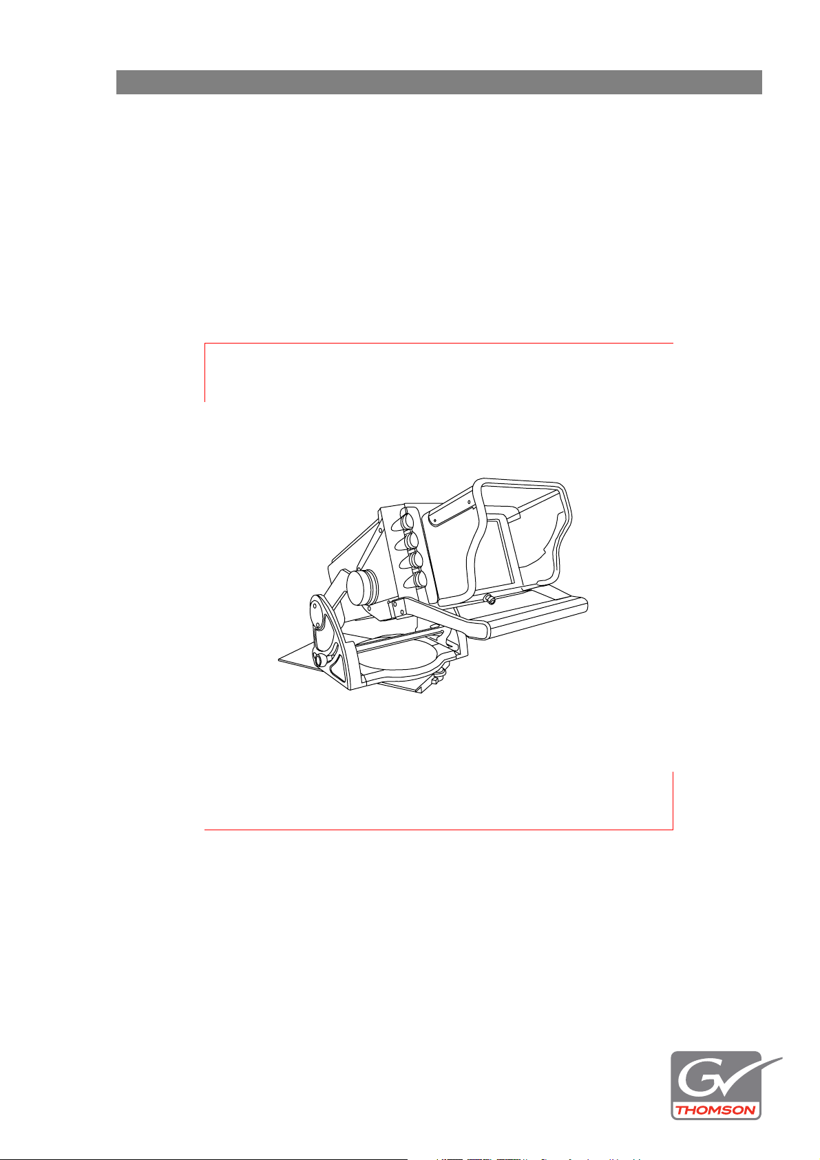
LDK 4021
HDTV 7-inch high brightness viewfinder
Page 2

Declaration of Conformity
FCC Class A Statement
We, Grass Valley Nederland B.V., Kapittelweg 10, 4827 HG Breda, The
Netherlands, declare under our sole responsibility that this product is in
compliance with the following standards:
- EN60950 : Safety
- EN55103-1: EMC (Emission)
- EN55103-2: EMC (Immunity)
following the provisions of:
a. the Safety Directives 73/23//EEC and 93/68/EEC
b. the EMC Directives 89/336/EEC and 93/68/EEC
This product generates, uses, and can radiate radio frequency energy and if not
installed and used in accordance with the instructions, may cause interference to
radio communications.
It has been tested and found to comply with the limits for a class A digital device
pursuant to part 15 of the FCC rules, which are designed to provide reasonable
protection against such interference when operated in a commercial environment.
Operation of this product in a residential area is likely to cause interference in
which case the user at his own expense will be required to take whatever
measures may be required to correct the interference.
Copyright
Trademarks
Website
Copyright Grass Valley Nederland B.V. 2008. Copying of this document and giving
it to others, and the use or communication of the contents thereof, are forbidden
without express authority. Offenders are liable to the payment of damages. All
rights are reserved in the event of the grant of a patent or the registration of a
utility model or design. Liable to technical alterations in the course of further
development.
Grass Valley and Infinity are trademarks of Grass Valley, Inc. All other tradenames
referenced are service marks, trademarks, or registered trademarks of their
respective companies.
Visit the Grass Valley public website to download the latest user’s guide updates
and additional information about your broadcast product:
www.thomsongrassvalley.com
Page 3

Table of contents
Chapter 1 – Installation
1.1 Introduction . . . . . . . . . . . . . . . . . . . . . . . . . . . . . . . . . . . . . . . . . . . . . . . . . . . . . . . . . . 9
1.2 Viewfinder support bracket. . . . . . . . . . . . . . . . . . . . . . . . . . . . . . . . . . . . . . . . . . . . . . 9
1.3 Mounting the viewfinder. . . . . . . . . . . . . . . . . . . . . . . . . . . . . . . . . . . . . . . . . . . . . . . 10
1.4 Sunhood . . . . . . . . . . . . . . . . . . . . . . . . . . . . . . . . . . . . . . . . . . . . . . . . . . . . . . . . . . . .11
Chapter 2 – Adjusting
2.1 Positioning . . . . . . . . . . . . . . . . . . . . . . . . . . . . . . . . . . . . . . . . . . . . . . . . . . . . . . . . . .13
2.1.1 Backwards and forwards . . . . . . . . . . . . . . . . . . . . . . . . . . . . . . . . . . . . . . . . . . 13
2.1.2 Tilt . . . . . . . . . . . . . . . . . . . . . . . . . . . . . . . . . . . . . . . . . . . . . . . . . . . . . . . . . . . 14
2.1.3 Lift . . . . . . . . . . . . . . . . . . . . . . . . . . . . . . . . . . . . . . . . . . . . . . . . . . . . . . . . . . . 14
2.1.4 Rotate . . . . . . . . . . . . . . . . . . . . . . . . . . . . . . . . . . . . . . . . . . . . . . . . . . . . . . . . 14
Chapter 3 – Operation
3.1 Controls . . . . . . . . . . . . . . . . . . . . . . . . . . . . . . . . . . . . . . . . . . . . . . . . . . . . . . . . . . . . 15
3.2 Indicators . . . . . . . . . . . . . . . . . . . . . . . . . . . . . . . . . . . . . . . . . . . . . . . . . . . . . . . . . . . 16
Chapter 4 – Specifications
4.1 Specifications for LDK 4021 . . . . . . . . . . . . . . . . . . . . . . . . . . . . . . . . . . . . . . . . . . . . 19
4.2 Connectors . . . . . . . . . . . . . . . . . . . . . . . . . . . . . . . . . . . . . . . . . . . . . . . . . . . . . . . . . .20
4.3 Dimensions . . . . . . . . . . . . . . . . . . . . . . . . . . . . . . . . . . . . . . . . . . . . . . . . . . . . . . . . .21
LDK 4021 HDTV 7-inch high brightness viewfinder User’s Guide (v2.0) 3
Page 4

End-of-life product recycling
Grass Valley’s innovation and excellence in product design also extends to the programs we’ve
established to manage the recycling of our products. Grass Valley has developed a
comprehensive end-of-life product take back program for recycle or disposal of end-of-life
products. Our program meets the requirements of the European Union’s WEEE Directive and
in the United States from the Environmental Protection Agency, individual state or local
agencies.
Grass Valley’s end-of-life product take back program assures proper disposal by use of Best
Available Technology. This program accepts any Grass Valley branded equipment. Upon
request, a Certificate of Recycling or a Certificate of Destruction, depending on the ultimate
disposition of the product, can be sent to the requester.
Grass Valley will be responsible for all costs associated with recycling and disposal, including
freight, however you are responsible for the removal of the equipment from your facility and
packing the equipment ready for pickup.
For further information on the Grass Valley product take back system please contact Grass
Valley at + 800 80 80 20 20 or +33 1 48 25 20 20 from most other countries. In the US and
Canada please call 800-547-8949 or 530-478-4148. Ask to be connected to the EH&S
Department. In addition, information concerning the program can be found at:
www.thomsongrassvalley.com/environment
4 LDK 4021 HDTV 7-inch high brightness viewfinder User’s Guide (v2.0)
Page 5

Important information
Read this information carefully before installing this equipment and retain them for future
reference. Read and comply with the warning and caution notices that appear in the manual.
Any changes or modifications not expressly approved in this manual could void your authority
to operate this equipment.
Safety Summary
This informaton is intended as a guide for trained and qualified personnel who are aware of
the dangers involved in handling potentially hazardous electrical/electronic equipment. It is
not intended to contain a complete list of all safety precautions which should be observed by
personnel in using this or other electronic equipment.
The installation of this equipment involves risks both to personnel and equipment and must
be performed only by qualified personnel exercising due care.
During installation and operation of this equipment, local building safety and fire protection
standards must be observed. Before connecting the equipment to the power supply of the
installation, the proper functioning of the protective earth lead of the installation needs to be
verified.
Whenever it is likely that safe operation is impaired, the apparatus must be made inoperative
and secured against any unintended operation. The appropriate servicing authority must then
be informed. For example, safety is likely to be impaired if the apparatus fails to perform the
intended function or shows visible damage.
Warnings
Warnings indicate danger that requires correct procedures or practices to prevent death or
injury to personnel.
• Do not modify this equipment;
• Installation of this equipment must only be performed by qualified personnel;
• Do not use any accessories other than those recommended by the manufacturer;
• In case of an emergency ensure that the power is disconnected;
• Mount equipment so that power lead can be accessed to disconnect power;
• Any interruption of the protection conductor inside or outside the apparatus, or
disconnection of the protective earth terminal, is likely to make the apparatus dangerous.
Intentional interruption is prohibited;
• Use only fuses of the type and rating specified;
• To prevent fire or shock hazard, do not expose the unit to rain or moisture;
• There are no user servicable parts inside. Refer servicing to qualified personnel only or
contact your local Grass Valley representative;
• Observe local building safety, fire protection and electrical installation standards during
installation and operation of this equipment;
• Before connecting the equipment to the power supply of the installation, verify the proper
functioning of the protective earth lead;
• Whenever it is likely that safe operation is impaired, the apparatus must be made
inoperative and secured against any unintended operation.
LDK 4021 HDTV 7-inch high brightness viewfinder User’s Guide (v2.0) 5
Page 6

Cautions
Cautions indicate procedures or practices that should be followed to prevent damage or
destruction to equipment or property.
• Do not subject the unit to severe shocks or vibration;
• Do not expose the unit to extremes of temperature;
• To prevent risk of overheating, ventilate the product correctly;
• Connect the product only to a power source with the specified voltage rating.
6 LDK 4021 HDTV 7-inch high brightness viewfinder User’s Guide (v2.0)
Page 7

Wichtige Hinweise
Lesen Sie bitte diese Hinweise genau bevor Sie diese Apparatur installieren und erhalten Sie Sie für
künftiges Nachslagen. Beachten und Lesen Sie alle mit “Achtung” und “Vorsicht”
gekennzeichneten Warnhinweise.
Änderungen haben zur Folge, dass die Garantie ungültig wird und der Benutzer für etwaige
durch die veränderte Ausrüstung verursachte Störungen haftbar gemacht werden könnte.
Sicherheit (Zusammenfassung)
Diese Informationen sind als Leitfaden für qualifiziertes Fachpersonal gedacht, das die
Gefahren beim Umgang mit potenziell gefährlicher elektrischer/elektronischer Ausrüstung
kennt. Es handelt sich dabei nicht um eine vollständige Zusammenstellung aller
Sicherheitsvorkehrungen, die beim Gebrauch dieser oder anderer elektronischer Geräte zu
beachten sind.
Die Montage, Wartung und Instandsetzung dieser Ausrüstung ist mit Risiken für Personal und
Ausrüstung verbunden und darf nur von qualifiziertem Personal vorgenommen werden, wobei
mit der nötigen Sorgfalt vorzugehen ist.
Beim Einbau und Betrieb dieser Ausrüstung müssen die örtlichen Gebäudesicherheits- und
Brandschutzvorschriften beachtet werden. Vor dem Anschluss der Ausrüstung an die
Stromversorgung der Anlage muss überprüft werden, ob der Schutzleiter intakt ist.
Wenn eine Beeinträchtigung des sicheren Betriebs wahrscheinlich ist, muss das Gerät außer
Betrieb gesetzt und gegen ungewollten Betrieb gesichert werden. Dann muss der zuständige
Kundendienst benachrichtigt werden. Eine Beeinträchtigung der Sicherheit ist zum Beispiel
dann wahrscheinlich, wenn das Gerät nicht wie vorgesehen funktioniert oder einen sichtbaren
Schaden aufweist.
Vorsich t
Mit “Vorsicht” wird auf eine Gefahr hingewiesen, die korrekte Arbeits- oder Verfahrensweisen
erfordert, um Tod oder Verletzung zu verhindern.
• An dieser Ausrüstung dürfen keine Änderungen vorgenommen werden;
• Die Montage dieser Ausrüstung darf nur von Fachpersonal vorgenommen werden;
• Es sollen nur von den Hersteller empfohlene Zubehöre verwendet werden;
• Bei Eintreten eines Notfalls unbedingt die Stromzufuhr abschalten;
• Ausrüstung so montieren, daß das Netzkabel zum Abschalten der Stromzufuhr zugänglich
ist;
• Jede Unterbrechung des Schutzleiters innerhalb oder ausserhalb des Geräts oder
Trennung der Schutzleiter-anschlussklemme Könnte das Gerät fefährlich machen. Eine
absichtliche Unterbrechung ist untersagt;
• Es dürfen nur Sicherungen des vorgeschriebenen Typs und Nennwerts verwendet
werden;
• Um Feuer oder Schlaggefahr vorzubeugen, soll das Produkt nie an Regen oder Feucht
ausgesetzt werden;
• Dieses Produkt enthält keine Anwenderteile. Reparatur und Wartung nur von
qualifiziertem Fachpersonal vornehmen lassen oder nehmen Sie Kontakt auf mit Ihrem
Grass Valley Vertretene;
LDK 4021 HDTV 7-inch high brightness viewfinder User’s Guide (v2.0) 7
Page 8

• Beim Einbau und Betrieb dieser Ausrüstung müssen die örtlichen Gebäudesicherheitsund Brandschutzvorschriften beachtet werden;
• Vor dem Anschluss der Ausrüstung an die Stromversorgung der Anlage muss überprüft
werden, ob der Schutzleiter intakt ist;
• Wenn eine Beeinträchtigung des sicheren Betriebs wahrscheinlich ist, muss das Gerät
außer Betrieb gesetzt und gegen ungewollten Betrieb gesichert werden.
Achtung
Mit “Achtung” werden Arbeitsanweisungen gekennzeichnet, die zu befolgen sind, um eine
Beschädigung oder Zerstörung der Ausrüstung bzw. von Eigentum zu verhindern.
• Dieses Produkt darf nicht an extremen stöße oder Zittern ausgesetzt werden;
• Dieses Produkt darf nicht an extremen Temperaturen ausgesetzt werden;
• Um einer Überhitzungsgefahr vorzubeugen, ist das Produkt korrekt zu belüften;
• Das Produkt darf nur an eine Stromquelle mit der vorgeschriebenen Nennspannung
angeschlossen werden.
Installation notices
For proper installation the following NEC articles should be noticed:
Regarding communication circuits:
– Installation of equipment (NEC article 800.18).
Regarding radio and television equipment:
– Avoid contact with conductors of other systems (NEC article 810.13);
Provide extensive, separate clearance requirements for indoor and outdoor locations (NEC
article 810.18).
8 LDK 4021 HDTV 7-inch high brightness viewfinder User’s Guide (v2.0)
Page 9

Chapter 1
Installation
1.1 Introduction
The LDK 4021 is a high quality HD 7-inch high brightness viewfinder. Due to its light-weight
construction the viewfinder is very easy to handle. The LDK 4021 is used with the Grass Valley
HD line of cameras (for example, LDK 4000 or LDK 8000).
1.2 Viewfinder support bracket
The supplied support bracket is required to mount the viewfinder on top of a Xpander/
SuperXpander. Refer to user’s guide of the Xpander/SuperXpander for the installation
instuctions for the bracket.
Note
☞
When the viewfinder is mounted on top of the LDK 6517 viewfinder support the viewfinder
support bracket is not needed.
LDK 4021 HDTV 7-inch high brightness viewfinder - User’s Guide (v2.0) 9
Page 10

Chapter 1 - Installation
1.3 Mounting the viewfinder
Caution
Switch off power of the SuperXpander before mounting the viewfinder.
Figure 1-1. Mounting the viewfinder
Caution
Always mount viewfinder before
pulling the vertical position knob.
viewfinder mount
retaining lever
viewfinder
locking levers
To mount the viewfinder on top of the SuperXpander proceed as follows:
1. Release the retaining lever on the viewfinder support and slide the viewfinder towards the
rear of the SuperXpander; fasten the lever.
2. Slide the viewfinder along the rails on top of the SuperXpander until it can go no further.
3. Push both viewfinder locking levers inwards and slide the viewfinder until it firmly
engages the connector.
4. Release the locking levers and ensure they click into the lock position (completely
outwards).
10 LDK 4021 HDTV 7-inch high brightness viewfinder - User’s Guide (v2.0)
Page 11

1.4 Sunhood
To attach the sunhood to the viewfinder proceed as follows:
1. Clip the top of the sunhood into the slot at the top-front of the viewfinder.
Figure 1-2. Attaching a sunhood
viewfinder hood support slot
off
Chapter 1 - Installation
-
+
-
+
-
+
on
off
hood fixation bracket
2. Swing the sunhood down and fasten it by pushing and turning the screw into the hood
fixation bracket.
Note
☞
The top part of the sunhood is hinged so that it can be moved up when using the viewfinder at
a high angle.
LDK 4021 HDTV 7-inch high brightness viewfinder - User’s Guide (v2.0) 11
Page 12

Chapter 1 - Installation
12 LDK 4021 HDTV 7-inch high brightness viewfinder - User’s Guide (v2.0)
Page 13

Chapter 2
Adjusting
2.1 Positioning
The viewfinder can be easily positioned to adapt to any viewing angle and situation. There are
four position adjustments:
• backwards and forwards,
• tilt,
• lift, and
• rotate.
2.1.1 Backwards and forwards
1. Loosen the viewfinder mount retaining lever on top of the SuperXpander.
2. Slide the viewfinder support mount along the rails until it is in the desired position.
3. Tighten the viewfinder retaining lever on top of the SuperXpander.
LDK 4021 HDTV 7-inch high brightness viewfinder - User’s Guide (v2.0) 13
Page 14

Chapter 2 - Adjusting
ilt
Figure 2-1. Positioning the viewfinder
2.1.2 Tilt
right rotation knob (2)
(not visible)
left rotation
knob (1)
lift
rotate
vertical position knob (4)
The viewfinder can be tilted very low when the camera is in a high position:
rotation locking wheel (5)
sunhood
t
handgrip (3)
2.1.3 Lift
2.1.4 Rotate
1. Hold the left rotation knob (1) with your left hand and loosen the right rotation knob (2)
with your right hand.
2. Tilt the viewfinder to the desired angle using the handgrip (3).
3. Fasten the right rotation knob (2) to fix the position.
1. Pull out the vertical position knob (4) with your left hand and lift the handgrip (3) with your
right hand.
2. The vertical postion can be set to four fixed postions with the vertical position knob (4).
3. Choose the desired postion and release the knob until it clicks.
The unit can rotate 90 degrees to the right and 180 degrees to the left. When rotated to the left
the viewfinder can be used to set up the lens while still observing the viewfinder picture.
1. Loosen the rotation locking wheel (5) and use the handgrip (3) to rotate the viewfinder.
2. Fasten the rotation locking wheel (5) to fix the position.
14 LDK 4021 HDTV 7-inch high brightness viewfinder - User’s Guide (v2.0)
Page 15

Chapter 3
Operation
3.1 Controls
horizontal
cursor line
(right)
horizontal
cursor line
(left)
vertical
cursor line
(top)
vertical
cursor line
(bottom)
cursor
frame
selection
off
-
+
-
+
-
+
on
off
Power switch
This switch is used to switch the power supply in the viewfinder on or off. A green LED near
the switch indicates that the unit is switched on.
Note
☞
The power to the viewfinder is supplied by the camera. When the camera is switched off the
viewfinder receives no power even when the power switch is on.
power
switch
brightness
adjust
contrast
adjust
aperture
correction
adjust
aperture
correction
on/off
Brightness adjust
Controls the brightness level of the viewfinder display.
Contrast adjust
Controls the contrast level of the viewfinder display.
LDK 4021 HDTV 7-inch high brightness viewfinder - User’s Guide (v2.0) 15
Page 16

Chapter 3 - Operation
Aperture correction adjust
Varies the amount of aperture correction applied to the viewfinder signal when the aperture
correction switch is in the On position.
Aperture correction switch
Switches the aperture correction of the viewfinder signal On and Off.
Cursor frame selection
Selects the cursor frame mode for viewfinder display: box type, deactivated, lines type.
Vertical cursor line
Shifts the top or bottom cursor lines in a vertical direction.
Horizontal cursor line
Shifts the left or right cursor lines in a horizontal direction.
3.2 Indicators
ISO
indicator
On Air
indicator
Call
indicator
Power indicator
This green LED indicates that the viewfinder is switched on.
On Air indicators
These red LEDs indicate that the camera is currently on air.
power
indicator
-
+
-
+
-
+
on
off
off
ISO
indicator
On Air
indicator
Call
indicator
ISO indicators
These yellow LEDs indicate that the camera is currently in ISO mode.
Call indicators
These green LEDs light to attracht attention when CALL is activated.
16 LDK 4021 HDTV 7-inch high brightness viewfinder - User’s Guide (v2.0)
Page 17

Chapter 3 - Operation
LDK 4021 HDTV 7-inch high brightness viewfinder - User’s Guide (v2.0) 17
Page 18

Chapter 3 - Operation
18 LDK 4021 HDTV 7-inch high brightness viewfinder - User’s Guide (v2.0)
Page 19

Chapter 4
Specifications
4.1 Specifications for LDK 4021
Item Value
Dimensions (L x W x H) 424 x 296 x 173 mm (16.7 x 11.7 x 6.8 in)
Weight (approx.) 7.3 kg (16.1 lbs)
Operating temperatures -20 to +45 °C (-4 to +113 °F)
Storage temperatures -25 to +70 °C (-13 to +140 °F)
Operating humidity 93% RH (non condensing)
Power supply 10.5 to 17 VDC
Power consumption 28 VA max (supplied by the Xpander/SuperXpander)
Supported formats 1080i59.94, 1080i50, 1080i48 (SMPTE 274)
720p59.94, 720p50 (SMPTE 296M)
CRT 7-inch high resolution type
Picture zoom zoom factor ~ 1.3 x
Geometric distortion 1.5% or less
Picture stability 1% of picture dimensions or better
Brightness 800 cd/m
Resolution Min. 800 horizontal lines in centre of screen at 500 cd/m
Frequency response 0.1 to 15 MHz (±1 dB )
15 to 27 MHz (+1/- 3 dB)
Aperture 0 to 12 dB (at approx. 12.5 MHz) variable adjustment
Black level stability Change of black level 2% with respect to white level
2
(nom.), 2,200 cd/m2 (peak)
2
LDK 4021 HDTV 7-inch high brightness viewfinder - User’s Guide (v2.0) 19
Page 20

Chapter 4 - Specifications
9
4.2 Connectors
Figure 4-1. Viewfinder connector
8 1
15-pin male D-connector
915
1. VF video
2. VF Ext video
3. VF Pb
4. GND
5. shield
6. +15 VDC
7. SCL-D
. VF video return
10. VF Ext video return
11. +15 VDC
12. GND
13. shield
14. VF Pr
15. SDA-D
8. INTN-D
20 LDK 4021 HDTV 7-inch high brightness viewfinder - User’s Guide (v2.0)
Page 21

4.3 Dimensions
215
23
Chapter 4 - Specifications
316
99
173
424
260
399
254
170
296
LDK 4021 HDTV 7-inch high brightness viewfinder - User’s Guide (v2.0) 21
Page 22

Chapter 4 - Specifications
22 LDK 4021 HDTV 7-inch high brightness viewfinder - User’s Guide (v2.0)
 Loading...