

Page 1

6.15.3 1
LDK 4016/05 7-inch Viewfinder User's Guide
LDK 4016/05
7-inch Viewfinder
with PIP
User's Guide
Contents
7-inch Viewfinder ................................................ 2
Front View LED's................................................ 3
Front View Switches ........................................... 4
How to use PIP................................................... 5
Positioning the Viewfinder .................................. 6
Page 2
2 6.15.3
LDK 4016/05 7-inch Viewfinder User's Guide
7-inch Viewfinder
1
Red On-air Lamps
These two red tally lamps on either side of the back
of the viewfinder light when the camera picture is onair.
2
Power Switch
This switch is used to switch the power supply to the
viewfinder on and off. The supply to the viwfinder is
supplied from the camera. When there is no camera
power the viewfinder receives no power even thought
the power switch may be on.
3
PIP size
This switch is used to switch the size of the PIP
signal to 1/9 or 1/16 of the viewfinder picture.
4
Reset button
This button resets the PIP signal to the top left
corner of the picture.
5
PIP border
This switch is used to switch the border of the PIP
signal on and off. This switch doesn't work in the
reverse mode.
6
Aspect Ratio Switch
This switch changes the aspect ratio of the viewfinder
display. The two positions are 4:3 and 16:9 aspect
ratios.
If the viewfinder is a part of the LDK 10 camera
system, the IIC-bus will be used and switch 3 then is
disabled.
1
2
3
4
5
6
Page 3

6.15.3 3
LDK 4016/05 7-inch Viewfinder User's Guide
Front View LED's
1
Call LED
This green LED lights to attract the cameraman's
attention.
2
On-air LEDs
These red LEDs light to indicate that the camera is
on-air.
3
ISO LED
This yellow LED lights to indicate that the camera
signal is being used though not necessarily on-air.
1
2
3
Page 4

4 6.15.3
LDK 4016/05 7-inch Viewfinder User's Guide
Front View Switches
1
Brightness Control
Controls the brightness of the viewfinder display.
2
Aperture Correction Control
This control varies the amount of aperture correction
applied to the viewfinder signal when the aperture
correction switch is in the ON position.
3
Aperture Correction Switch
This switch is used to switch the aperture correction
of the viewfinder signal on and off.
4
Contrast Control
Controls the contrast of the viewfinder display.
5
Picture In Picture Switch
This switch is used to switch on the PIP signal.
6
Cursor Frame Selection
Selects the cursor frame mode for display on the
viewfinder:
Off = Deactivated
# = Lines
= Box
Off = Deactivated
7, 8
Cursor Line Control
Shifts the horizontal cursor lines in a vertical direction.
9, 10
Cursor Line Control
Shifts the vertical cursor lines in a horizontal direction.
1
2
3
4
5
6
7
8
9
10
Page 5

6.15.3 5
LDK 4016/05 7-inch Viewfinder User's Guide
How to use PIP
The PIP signal is controlled by a toggle switch and
works as follows:
The first time toggle up gives the PIP signal in the
top left corner of the total picture.
The second time toggle up moves the PIP signal
to the top right corner of the picture.
The third time toggle up moves the PIP signal to
the bottom right corner of the picture.
The fourth time toggle up moves the PIP signal to
the bottom left corner of the picture.
The fifth time toggle up moves the picture back to
the top left corner of the picture.
Holding toggle up longer then a second switches
off the PIP signal.
After switching on the PIP signal giving a toggle
down switches the PIP in reverse mode. This
means PIP signal total view and Camera signal
PIP view, which can be recognised on the flashing
border of the PIP view.
Toggle down again switches back to normal PIP
mode.
Note:
When the PIP signal is switched on, the
Viewfinder shows the Camera signal and the PIP
signal shows the Ext. 1, Ext. 2 or the Y/Ext signal,
which can be operated from the Rear Control
Panel of the LDK10 Camera.
Toggle one
Toggle two
Toggle three
Toggle four
Page 6

6 6.15.3
LDK 4016/05 7-inch Viewfinder User's Guide
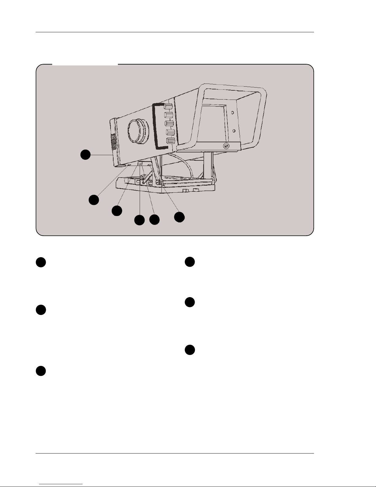
Positioning the Viewfinder
To swing out viewfinder
a. Unlock the transport lock lever.
b. Turn both unlocking knobs marked FIXED/FREE
simultaneously in the FREE direction and pull up
the back of the viewfinder.
c. The viewfinder is now unlocked. Tilt or swing out
the viewfinder into the desired position.
Locking the viewfinder
a. Rotate the two unlocking knobs marked FIXED/
FREE simultaneously in FREE direction and push
the back of the viewfinder down all the way.
b. Hold the two unlocking knobs in the FREE position
and push down the viewfinder until it clicks into
place.
c. Lock the transport lock lever.
Transport Lock
Lever
Unlocking
Locking
Hood Lock
Levers
 Loading...