

Page 1

KAYENNE
VIDEO PRODUCTION CENTER
Release Notes
Software Version 3.0
071868703
JANUARY 2011
Page 2

Affiliate with the N.V. KEMA in The Netherlands
CERTIFICATE
Certificate Number: 510040.001
The Quality System of:
Thomson Inc, and its worLdwide Grass Valley division affiliates DBA
GRASS VALLEY
Headquarters
400 Providence Mine Rd
Nevada City, CA 95959
United States
15655 SW Greystone Ct.
Beaverton, OR 97006
United States
10 Presidential Way
Suite 300
Woburn, MA 01801
United States
Kapittelweg 10
4827 HG Breda
The Nederlands
7140 Baymeadows Way
Ste 101
Jacksonville, FL 32256
United States
2300 So. Decker Lake Blvd.
Salt Lake City, UT 84119
United States
Rue du Clos Courtel
CS 31719
35517 Cesson-Sevigné Cedex
France
1 rue de l’Hautil
Z.I. des Boutries BP 150
78702 Conflans-Sainte
Honorine Cedex
France
Technopole Brest-Iroise
Site de la Pointe du Diable
CS 73808
29238 Brest Cedex 3
France
40 Rue de Bray
2 Rue des Landelles
35510 Cesson Sevigné
France
Spinnereistrasse 5
CH-5300 Turgi
Switzerland
Brunnenweg 9
D-64331 Weiterstadt
Germany
Carl-Benz-Strasse 6-8
67105 Schifferstadt
Germany
Including its implementation, meets the requirements of the standard:
ISO 9001:2008
Scope:
The design, manufacture and support of video and audio hardware and software products and
related systems
.
This Certificate is valid until: June 14, 2012
This Certificate is valid as of: June 14, 2009
Certified for the first time: June 14, 2000
H. Pierre Sallé
President
KEMA-Registered Quality
The method of operation for quality certification is defined in the KEMA General Terms
And Conditions For Quality And Environmental Management Systems Certifications.
Integral publication of this certificate is allowed.
KEMA-Registered Quality, Inc.
4377 County Line Road
Chalfont, PA 18914
Ph: (215)997-4519
Fax: (215)997-3809
CRT 001 073004
Accredited By:
ANAB
Page 3

KAYENNE
VIDEO PRODUCTION CENTER
Release Notes
Software Version 3.0
071868703
JANUARY 2011
Page 4
Contacting Grass Valley
International
Support Centers
Local Support
Centers
(available
during normal
business hours)
France
24 x 7
Australia and New Zealand: +61 1300 721 495 Central/South America: +55 11 5509 3443
Middle East: +971 4 299 64 40 Near East and Africa: +800 8080 2020 or +33 1 48 25 20 20
Europe
+800 8080 2020 or +33 1 48 25 20 20
Hong Kong, Taiwan, Korea, Macau: +852 2531 3058 Indian Subcontinent: +91 22 24933476
Asia
Southeast Asia/Malaysia: +603 7805 3884 Southeast Asia/Singapore: +65 6379 1313
China: +861 0660 159 450 Japan: +81 3 5484 6868
Belarus, Russia, Tadzikistan, Ukraine, Uzbekistan: +7 095 2580924 225 Switzerland: +41 1 487 80 02
S. Europe/Italy-Roma: +39 06 87 20 35 28 -Milan: +39 02 48 41 46 58 S. Europe/Spain: +34 91 512 03 50
Benelux/Belgium: +32 (0) 2 334 90 30 Benelux/Netherlands: +31 (0) 35 62 38 42 1 N. Europe: +45 45 96 88 70
Germany, Austria, Eastern Europe: +49 6150 104 444 UK, Ireland, Israel: +44 118 923 0499
Copyright © Grass Valley USA, LLC. All rights reserved.
This product may be covered by one or more U.S. and foreign patents.
United States/Canada
24 x 7
+1 800 547 8949 or +1 530 478 4148
Grass Valley Web Site
The www.grassvalley.com web site offers the following:
Online User Documentation — Current versions of product catalogs, brochures,
data sheets, ordering guides, planning guides, manuals, and release notes
in .pdf format can be downloaded.
FAQ Database — Solutions to problems and troubleshooting efforts can be
found by searching our Frequently Asked Questions (FAQ) database.
Software Downloads — Download software updates, drivers, and patches.
4 KAYENNE — Release Notes
Page 5

Contents
Kayenne Release Notes . . . . . . . . . . . . . . . . . . . . . . . . . . . . . . . . . . . . . . . . . . . . . . . . . . 7
Contents
Introduction . . . . . . . . . . . . . . . . . . . . . . . . . . . . . . . . . . . . . . . . . . . . . . . . . . . . . . . . . . . 7
Changes in Release 3.0 . . . . . . . . . . . . . . . . . . . . . . . . . . . . . . . . . . . . . . . . . . . . . . . . 7
New in Release 3.0 . . . . . . . . . . . . . . . . . . . . . . . . . . . . . . . . . . . . . . . . . . . . . . . . . . 7
Improved in Release 3.0 . . . . . . . . . . . . . . . . . . . . . . . . . . . . . . . . . . . . . . . . . . . . . 8
Conversion of E-MEM Effects from Prior Releases . . . . . . . . . . . . . . . . . . . . . . . . 8
Converting Version 2.0 Effects: . . . . . . . . . . . . . . . . . . . . . . . . . . . . . . . . . . . . . . . 8
Converting Version 1.5 Effects: . . . . . . . . . . . . . . . . . . . . . . . . . . . . . . . . . . . . . . . 8
Camera Control with Ethernet Tally . . . . . . . . . . . . . . . . . . . . . . . . . . . . . . . . . . . . . . 9
Basic Configuration. . . . . . . . . . . . . . . . . . . . . . . . . . . . . . . . . . . . . . . . . . . . . . . . . . . 9
Node Settings . . . . . . . . . . . . . . . . . . . . . . . . . . . . . . . . . . . . . . . . . . . . . . . . . . . . . 11
Source Definitions . . . . . . . . . . . . . . . . . . . . . . . . . . . . . . . . . . . . . . . . . . . . . . . . . 11
Acquire Resources . . . . . . . . . . . . . . . . . . . . . . . . . . . . . . . . . . . . . . . . . . . . . . . . . 13
Switcher Camera Tally . . . . . . . . . . . . . . . . . . . . . . . . . . . . . . . . . . . . . . . . . . . . . 14
Camera Operations . . . . . . . . . . . . . . . . . . . . . . . . . . . . . . . . . . . . . . . . . . . . . . . . . . 16
Source Ops . . . . . . . . . . . . . . . . . . . . . . . . . . . . . . . . . . . . . . . . . . . . . . . . . . . . . . . 16
Multi-Function Module. . . . . . . . . . . . . . . . . . . . . . . . . . . . . . . . . . . . . . . . . . . . . 19
Macro Editor . . . . . . . . . . . . . . . . . . . . . . . . . . . . . . . . . . . . . . . . . . . . . . . . . . . . . . . . . 21
Offline Macro Editing with the Frame Simulator. . . . . . . . . . . . . . . . . . . . . . . . . 21
Configuring the Frame Simulator . . . . . . . . . . . . . . . . . . . . . . . . . . . . . . . . . . . . 21
Configuring the Kayenne Menu . . . . . . . . . . . . . . . . . . . . . . . . . . . . . . . . . . . . . 22
Macro Catalog Menu Enhancement . . . . . . . . . . . . . . . . . . . . . . . . . . . . . . . . . . . . 22
Macro Edit Menus . . . . . . . . . . . . . . . . . . . . . . . . . . . . . . . . . . . . . . . . . . . . . . . . . . . 23
Macro Editing. . . . . . . . . . . . . . . . . . . . . . . . . . . . . . . . . . . . . . . . . . . . . . . . . . . . . . . 24
Line Editing. . . . . . . . . . . . . . . . . . . . . . . . . . . . . . . . . . . . . . . . . . . . . . . . . . . . . . . 25
Macro Editing/Organizing Using Buttons . . . . . . . . . . . . . . . . . . . . . . . . . . . . 27
Creating a New Macro . . . . . . . . . . . . . . . . . . . . . . . . . . . . . . . . . . . . . . . . . . . . . . . 28
Transition Chaining . . . . . . . . . . . . . . . . . . . . . . . . . . . . . . . . . . . . . . . . . . . . . . . . . . . 29
Background Transition Chaining . . . . . . . . . . . . . . . . . . . . . . . . . . . . . . . . . . . . . . 30
Partition Sync Mode . . . . . . . . . . . . . . . . . . . . . . . . . . . . . . . . . . . . . . . . . . . . . . . . . 31
Partition Sync Locks Primary/Secondary Mode On . . . . . . . . . . . . . . . . . . . . 32
Operations . . . . . . . . . . . . . . . . . . . . . . . . . . . . . . . . . . . . . . . . . . . . . . . . . . . . . . . . . 32
Creating Primary and Secondary MEs (Dual Feed) . . . . . . . . . . . . . . . . . . . . . 32
Multiple Feed . . . . . . . . . . . . . . . . . . . . . . . . . . . . . . . . . . . . . . . . . . . . . . . . . . . . . 33
Including Source Substitutions . . . . . . . . . . . . . . . . . . . . . . . . . . . . . . . . . . . . . . 33
File OPs . . . . . . . . . . . . . . . . . . . . . . . . . . . . . . . . . . . . . . . . . . . . . . . . . . . . . . . . . . . . 33
New Black Key Source . . . . . . . . . . . . . . . . . . . . . . . . . . . . . . . . . . . . . . . . . . . . . . . . . 34
Router Control of Aux Busses. . . . . . . . . . . . . . . . . . . . . . . . . . . . . . . . . . . . . . . . . . . 35
E-MEM Enhancements. . . . . . . . . . . . . . . . . . . . . . . . . . . . . . . . . . . . . . . . . . . . . . . . . 37
ME Partition Control Moved . . . . . . . . . . . . . . . . . . . . . . . . . . . . . . . . . . . . . . . . 37
New Globals Sub-level . . . . . . . . . . . . . . . . . . . . . . . . . . . . . . . . . . . . . . . . . . . . . 37
Master E-MEM Module Enhancements. . . . . . . . . . . . . . . . . . . . . . . . . . . . . . . . . . . 38
Master E-MEM Module Edit Menu Reorganized . . . . . . . . . . . . . . . . . . . . . . . 38
Get and Put Added To Master E-MEM Module . . . . . . . . . . . . . . . . . . . . . . . . 38
New Bus Delegate and Shift Button Source Colors . . . . . . . . . . . . . . . . . . . . . . . . . 39
ClipStore Enhancement . . . . . . . . . . . . . . . . . . . . . . . . . . . . . . . . . . . . . . . . . . . . . . . . 40
DVCPRO Record Mode Added. . . . . . . . . . . . . . . . . . . . . . . . . . . . . . . . . . . . . . . . 40
Kayenne Software Update . . . . . . . . . . . . . . . . . . . . . . . . . . . . . . . . . . . . . . . . . . . . . . 41
KAYENNE — Release Notes 5
Page 6

Contents
Introduction. . . . . . . . . . . . . . . . . . . . . . . . . . . . . . . . . . . . . . . . . . . . . . . . . . . . . . . . 41
Materials Required . . . . . . . . . . . . . . . . . . . . . . . . . . . . . . . . . . . . . . . . . . . . . . . . 41
Software Update Procedure . . . . . . . . . . . . . . . . . . . . . . . . . . . . . . . . . . . . . . . . . . 41
Backup Current Configuration and Effects Files . . . . . . . . . . . . . . . . . . . . . . . 42
Deploy Kayenne Update Package Files and Installer . . . . . . . . . . . . . . . . . . . 42
Kayenne Installer Program Description . . . . . . . . . . . . . . . . . . . . . . . . . . . . . . 46
System Update (Video Processor Frame & Control Panels). . . . . . . . . . . . . . 47
Kayenne Menu Panel Application Installation/Update. . . . . . . . . . . . . . . . . 49
Clear NV RAM for Control Panel and Frame. . . . . . . . . . . . . . . . . . . . . . . . . . 54
Calibrate the Lever Arm and Joystick . . . . . . . . . . . . . . . . . . . . . . . . . . . . . . . . 54
Update Additional Kayenne Menu Panels or PCs. . . . . . . . . . . . . . . . . . . . . . 55
First Time Kayenne Menu on PC Installation. . . . . . . . . . . . . . . . . . . . . . . . . . 55
NetConfig and Newton Configurator Installation. . . . . . . . . . . . . . . . . . . . . . 56
Check Software Versions . . . . . . . . . . . . . . . . . . . . . . . . . . . . . . . . . . . . . . . . . . . 56
Confirm System Operation . . . . . . . . . . . . . . . . . . . . . . . . . . . . . . . . . . . . . . . . . 56
Backup New Configuration and Effects Files . . . . . . . . . . . . . . . . . . . . . . . . . . 57
Other Kayenne Systems Software Update . . . . . . . . . . . . . . . . . . . . . . . . . . . . . . 57
Individual Kayenne System Component Update . . . . . . . . . . . . . . . . . . . . . . . . 57
Removing Kayenne Software . . . . . . . . . . . . . . . . . . . . . . . . . . . . . . . . . . . . . . . . . 58
Kayenne Menu Panel Application Removal. . . . . . . . . . . . . . . . . . . . . . . . . . . 58
Kayenne Deployment Tool Files Removal . . . . . . . . . . . . . . . . . . . . . . . . . . . . 58
Removing Using the Windows OS. . . . . . . . . . . . . . . . . . . . . . . . . . . . . . . . . . . 59
Kayenne System IP Addresses . . . . . . . . . . . . . . . . . . . . . . . . . . . . . . . . . . . . . . . . . . 59
Default IP Addresses . . . . . . . . . . . . . . . . . . . . . . . . . . . . . . . . . . . . . . . . . . . . . . . . 59
New Single Control Surface Kayenne Systems . . . . . . . . . . . . . . . . . . . . . . . . . . 60
Multiple Control Surfaces and Suites . . . . . . . . . . . . . . . . . . . . . . . . . . . . . . . . . . 60
6 KAYENNE — Release Notes
Page 7

Version 3.0
Kayenne Release Notes
Introduction
This document describes installation and other information specific to
Kayenne Video Production Center Release 3.0 software. See
Kayenne system update instructions.
Changes in Release 3.0
JANUARY 2011
page 41 for
New in Release 3.0
• New Macro Editor (see page 21)
• Camera Control with Ethernet Tally (see page 9)
• Transition Chaining (see page 29)
• Router Control of Aux Busses (see page 35)
KAYENNE — Release Notes 7
Page 8

Ver sio n 3. 0
Improved in Release 3.0
• E-MEM Enhancements:
• ME partition control (see page 37)
• New Globals sub-level (see page 37)
• Master E-MEM Module Enhancements (added GET and PUT) (see
page 38)
• Local E-MEM Module Enhancement:
• Added four-character macro names (see page 22)
• Added DPOP of Menu button to Timeline View (SPOP to Timeline
Edit)
• New Source: Black Video/Black Key (see page 34)
• Source Colors now supported for Shift and Bus Delegate buttons (see
page 39)
• ClipStore Enhancement: Addition of option to record in DVCPRO HD
mode (as an alternative to AVC-Intra) (see page 40)
• Transition Module Enhancement: Status display now shows key priorities during normal operation and transition rates when the
button is pressed.
Conversion of E-MEM Effects from Prior Releases
On loading E-MEMs created with version 1.5 or 2.0 software, they are automatically converted into version 3.0 format. This conversion process is
indicated in the menu status box. It is strongly recommended that old
effects are loaded and then re-saved in version 3.0 format to avoid the over
head of conversion each time the effect is loaded.
Although significant conversion automatically takes place, there are a few
exceptions which require manual modification of older effects.
Converting Version 2.0 Effects:
No action required.
Converting Version 1.5 Effects:
Trans Rate
-
eDPM effects that are required to be controlled by Master E-MEM, need to
have a keyframe inserted at the beginning and end of the effect on the cor
responding Primary or Secondary Master E-MEM Proxy level.
8 KAYENNE — Release Notes
-
Page 9

Camera Control with Ethernet Tally
Kayenne Camera Integration provides the ability to place cameras into a
usable but not fully shaded setup/rehearsal mode. The Kayenne Switcher
can connect to up to 99 cameras via the Grass Valley LDK Connect
Gateway. Cameras can be acquired by multiple suites.
Switcher camera control is provided by the Menu Panel and Multi-Function Module in the Control Panel.
Camera control from the Kayenne system makes camera source setup fast
and easy by allowing you to:
• Turn color bars on/off to quickly identify which source is associated
with a camera,
• Control a subset of camera settings:
• Auto Iris enable/disable,
• Auto Black level (trigger),
• ND (Neutral Density) Filter settings, and
Camera Control with Ethernet Tally
• Load a Scene File with a single button push or recall a Scene File with
an E-MEM.
Note The Camera sub-level is assigned to an E-MEM level in the Menu Panel.
Ethernet Tally allows you to:
• Tally camera associated sources using Tally Calcs and
• Tally the Red, Yellow, or Green indicator on the camera from the
Basic Configuration
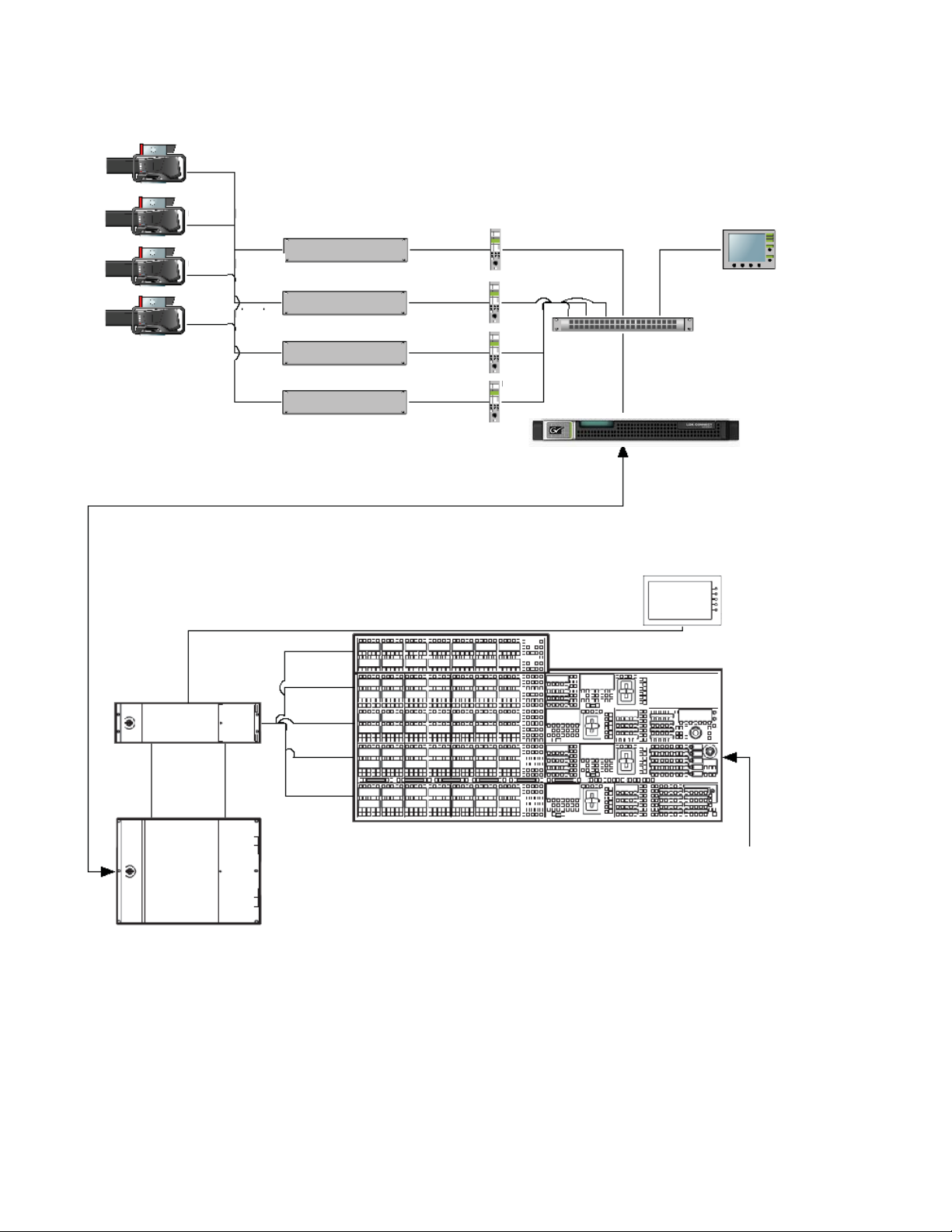
The Kayenne system uses Ethernet to communicate with the LDK Camera
Connect Gateway (
Eng Setup menu.
switcher Menu Panel/Control Panel.
Figure 1). Some basic configuration is required in the
KAYENNE — Release Notes 9
Page 10
Ver sio n 3. 0
8623267_36
Video Processing Frame
10/100
MB
1 GB
PCU
Power and Data Cables
LDK Connect Gateway to Kayenne Ethernet Interconnect
Menu Panel
OCP
OCP
OCP
OCP
MCP
Camera Head
Camera Head
Camera Head
Camera Head
Base Station
Base Station
Base Station
Base Station
Ethernet Switch
LDK Connect Gateway
Multi-Function
Module
Figure 1. Kayenne System Interconnection with Camera Gateway
10 KAYENNE — Release Notes
Page 11
Node Settings
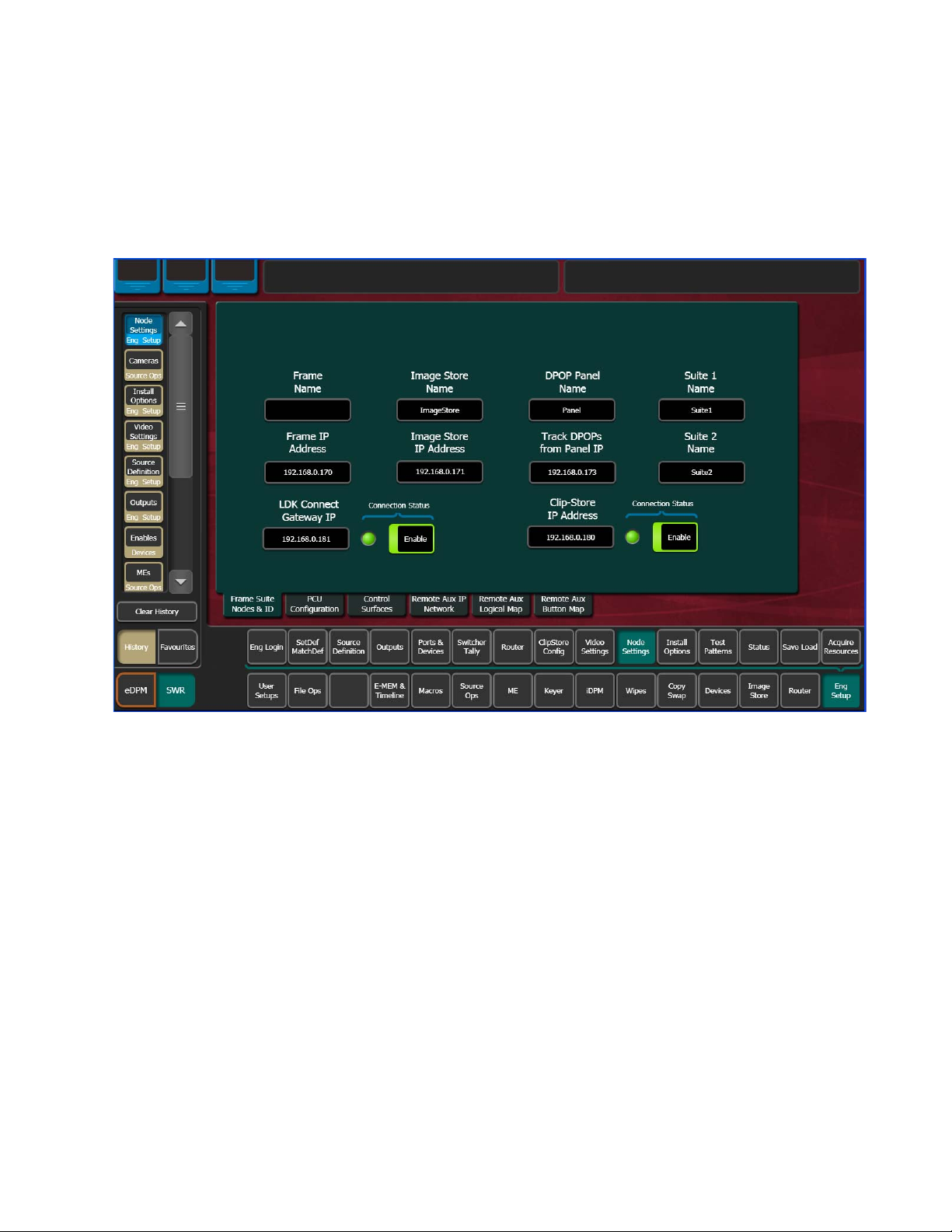
In the Eng Setup, Node Settings menu, enter a valid IP Address for the
camera gateway and touch the
Connect LED will turn green (
Figure 2. Camera IP/Enable, Node Settings Menu
Camera Control with Ethernet Tally
Enable button. When connected, the LDK
Figure 2).
Source Definitions
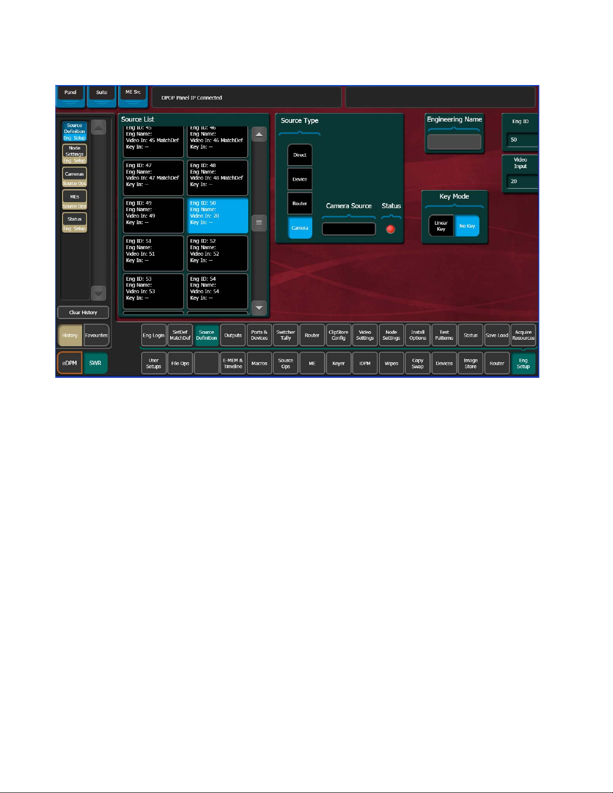
To enable camera control from the Kayenne, the source is defined as a
“Camera” type then assigned as a camera in the Eng Setup, Source Defini
tion menu (Figure 3).
-
KAYENNE — Release Notes 11
Page 12
Ver sio n 3. 0
Figure 3. Camera Source Type, Source Definition Menu
1. Touch the desired source in the Source List (Figure 3).
2. Set the Video Input and Key Mode (see the Kayenne User Manual for
more information).
3. Touch the Camera source type button in the Source Type pane (Figure 3).
Once the “Source Type” is defined as Camera, the Camera Source can
be defined.
12 KAYENNE — Release Notes
Page 13
Camera Control with Ethernet Tally
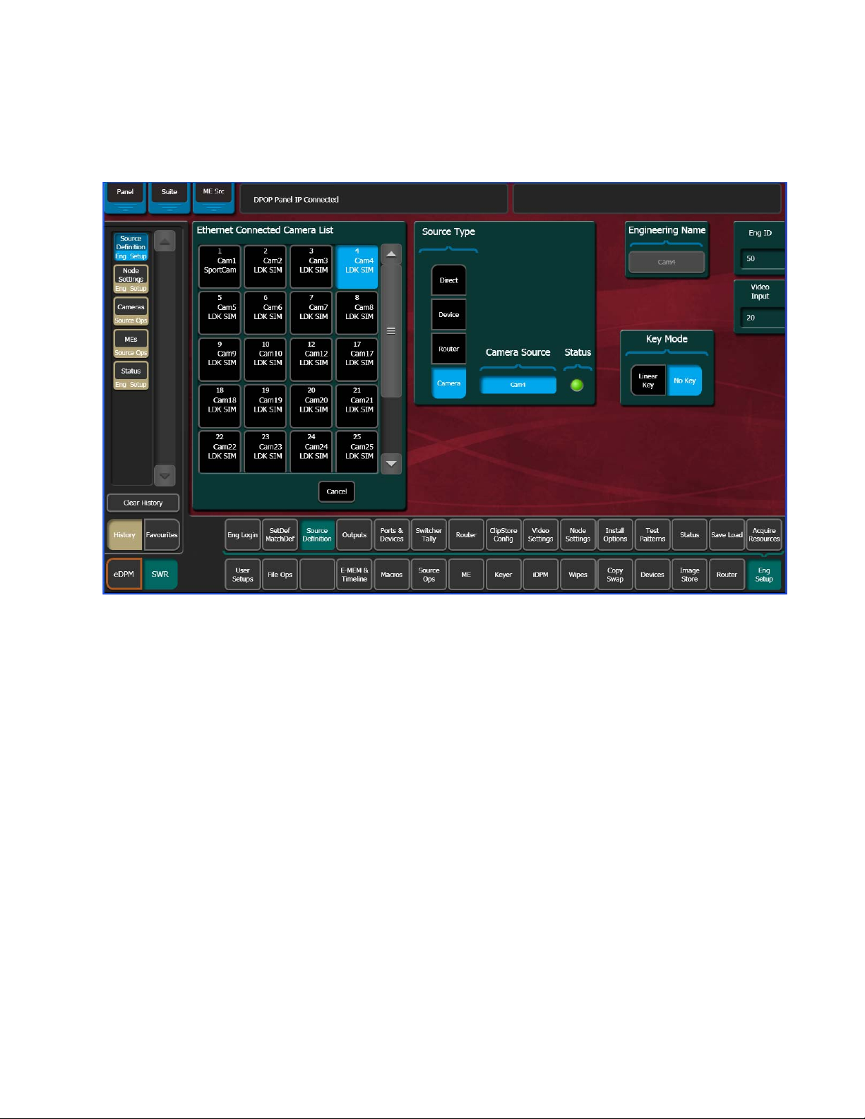
4. Tou ch the Camera Source data pad—the Ethernet Connected Camera List
pane is displayed (
Figure 4. Ethernet Connected Camera List, Eng Setup, Source Definition Menu
Figure 4).
5. Touch a camera in the Ethernet Connected Camera List.
The Ethernet Connected Camera List pane closes and the selected
camera’s Engineering Name is defined by the selection automatically.
A green
Note The Engineering Name of the source becomes “Cam##” and cannot be edited,
however the Eng. Source, Panel, OLED, and Menu Name can be changed in
the Source Patch menu (see the
tion).
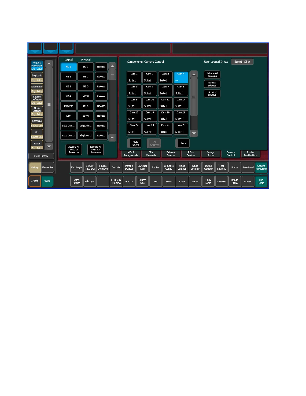
Acquire Resources
A camera resource can be acquired by Suite 1 or Suite 2 but not both
(E-MEM control is only from the suite currently controlling the camera
source). Camera resources are acquired in the Eng Setup, Acquire
Resources, Camera Control menu (
Status LED signifies a connected camera (Figure 4).
Kayenne User Manual for more informa-
Figure 5).
KAYENNE — Release Notes 13
Page 14
Ver sio n 3. 0
Figure 5. Camera Control, Eng Setup, Acquire Resources Menu
Acquire control of camera components in another suite by releasing one,
several, or all components from the current suite using the
Release All Cameras buttons, changing suites, then acquiring those com-
and
ponents in the other suite. For more information on acquiring resources, see
the Kayenne User Manual.
1. Select the components (cameras) you wish to acquire in another suite in
the Components: Camera Control pane (
2. Release those components using the release buttons.
3. Go to the Eng Login menu, and touch the Change Identity data pad.
4. Touch the data pad of the desired suite.
5. Return to the Eng Setup, Acquire, Camera Control menu and touch the
component buttons you wish to acquire to the suite.
6. Tou ch t he Acquire Selected button.
Switcher Camera Tally
The Kayenne 3.0 software provides a quickly connected, reliable, three
color tally (Red, Yellow, and Green) to Grass Valley cameras.
Release Selected
Figure 5).
Camera Tally controls have been added to the Kayenne Menu and the
Control Panel through the Multi-Function Module.
14 KAYENNE — Release Notes
Page 15
Camera Control with Ethernet Tally
Menu Panel
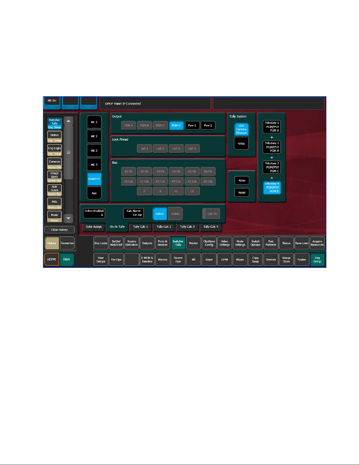
The Relay Tally category button in the Eng Setup menu has been changed
to
Switcher Tally and a Tally System pane has been added with Relay and LDK
Camera Ethernet
Figure 6. Switcher Tally LDK Camera Ethernet Menu
selector buttons to change tally menus (Figure 6).
Tally Calc Menus
As with Relay Tally, the LDK Camera Ethernet menu is used to select calculators, name calculators, and assign bus contributors to tributaries (see
the Kayenne Installation & Service Manual for more information).
Colors Enabled—Reports which colors are currently using that calculator, by
color letter corresponding to the viewfinder indicators (
• R (Red=On-Air),
• Y (Yellow=media (record)), and
• G (Green=ND/RE or ‘Call’).
Figure 6):
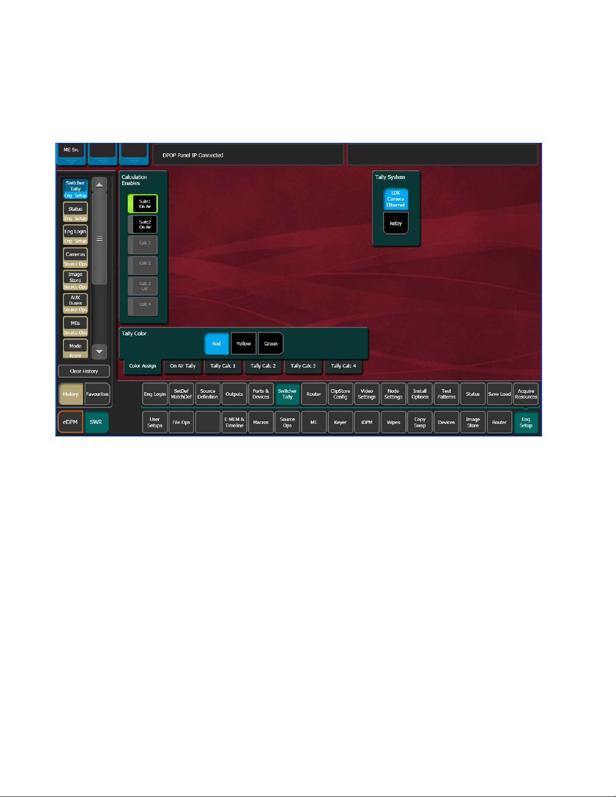
Color Assign Menu
Assigning a source as a Camera type and giving it a Camera Number is
similar to assigning a source to a relay in a Relay Tally Group (see the
Kayenne Installation & Service Manual).
KAYENNE — Release Notes 15
Page 16
Ver sio n 3. 0
The Color Assign menu is used to assign the Tally Calculators to the Tally
Colors. Touch the Eng Setup, Switcher Tally, Color Assign menu tab to
access this menu (
Figure 7. Color Assign Menu
Figure 7).
Camera Operations
Camera control from the Kayenne switcher provides remote control of a
subset of camera functions.
Source Ops
Camera user operations from the menu are performed in the Source Ops,
Cameras, Live Ops menu tab (
Figure 8).
16 KAYENNE — Release Notes
Page 17
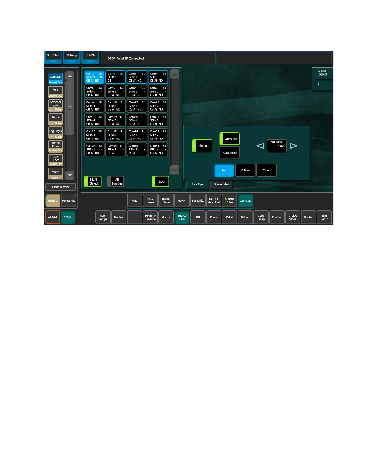
Figure 8. Source Ops, Cameras, Live Ops Menu
Camera Control with Ethernet Tally
Live Ops
Kayenne camera control provides the ability to place cameras into a usable
but not fully shaded setup/rehearsal mode using the menu buttons in the
Live Ops menu tab (
• Camera Sources—Select from 1-99 defined camera sources for control.
Color Bars—Enable/disable color bars to verify the camera as the associ-
•
ated source.
Auto Iris—Enable/disable camera’s Auto Iris.
•
Auto Black—Triggers a reset of camera’s black level.
•
ND (Neutral Density) Filter— Changes the neutral density filter wheel set-
•
ting.
Use back and forward arrow buttons (Figure 8) to scroll through and
enable 1/4, 1/16, 1/64 filter wheel settings, or CLR to clear the filter
wheel setting.
The Red, Yellow, and Green buttons allow you to test the camera tally colors
and/or send a call to the camera operator (for more information about
camera tally see
Figure 8):
Switcher Camera Tally on page 14).
KAYENNE — Release Notes 17
Page 18
Ver sio n 3. 0
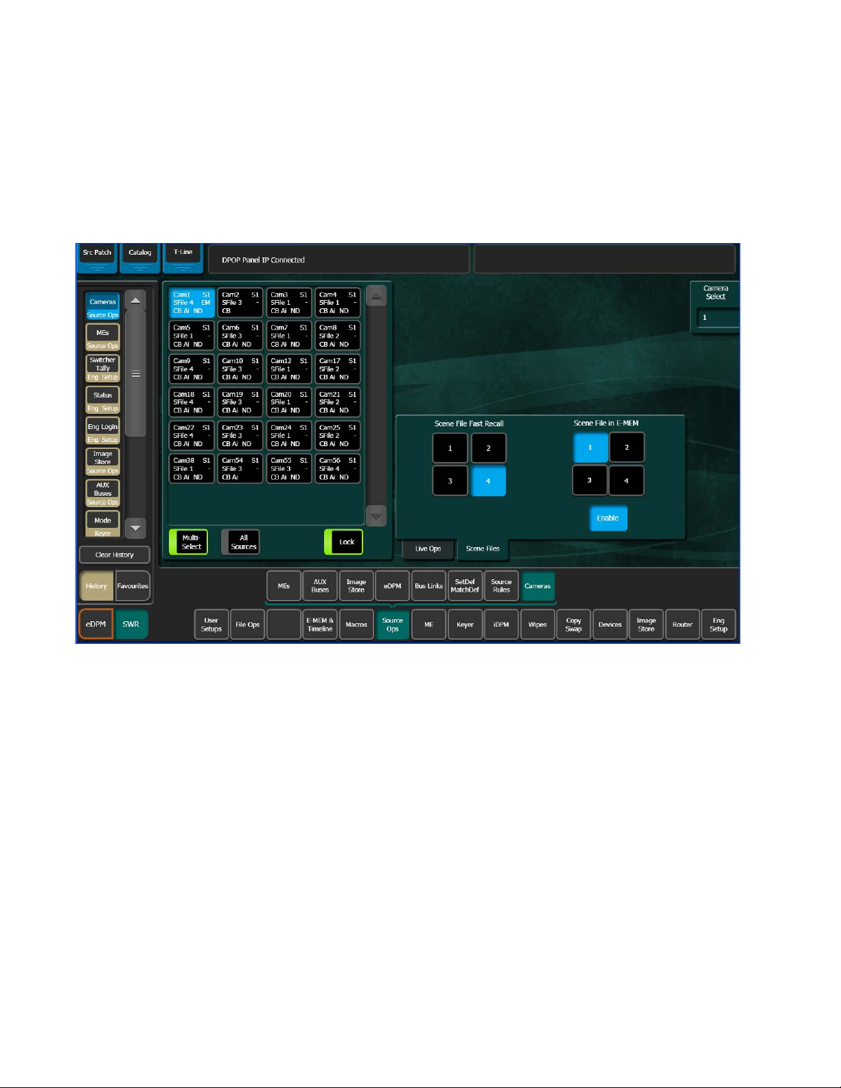
Scene Files
Up to four Scene Files saved by a camera operator can be quickly loaded to
selected cameras with the
E-MEM, using the
eras, Scene Files menu tab (Figure 9).
Figure 9. Source Ops, Cameras, Scene Files Menu
Scene File in E-MEM (1-4) buttons, in the Source Ops, Cam-
Fast Recall (1-4) buttons or recalled as part of an
Scene File Fast Recall—Allows you to recall scene files 1, 2, 3, or 4 to all
selected cameras in the Camera Source list. Simply select a camera source
or sources and touch a
Scene File in E-MEM—The Camera level button has been added to the User
Setups, E-MEM Prefs menu and therefore camera sub-levels can be
assigned to levels (and are definable) and recalled as part of an E-MEM (see
the Kayenne User Manual for more E-MEM Preference information).
E-MEMs can be used for example so the TD could recall and turn off a Star
Filter on all cameras instead of it being an engineering task.
1. Touch a camera source or sources in the Camera Sources list.
2. In the Scene Files menu, touch the numbered Scene File in E-MEM (1-4)
button for the scene file you wish to save as part of an E-MEM.
Scene File Fast Recall (1-4) button (Figure 9).
3. Tou ch t he Enable button (highlights blue when on).
EM (for E-MEM) is displayed in the selected camera’s button data.
18 KAYENNE — Release Notes
Page 19

4. Go to the Cameras E-MEM Prefs level by touching User Setups, Suite Prefs,
Wipeipe
1
KeyKey
5
KeyKey
3
KeyKey
1
Wipeipe
2
KeyKey
6
KeyKey
4
KeyKey
2
Adel Last
SF-1 ND+ND-ABLKCBARSF-2
SF-3 RED YELO
GRN
SF-4
Home
8623267_37
AIRS
Camera
Cam1
Filter
1/64
E-MEM Prefs, Cameras.
5. Touch the level to which you wish to assign the Camera’s sub-level.
6. Tou ch Done.
7. Build an E-MEM recalling the level with the camera sub-level assigned.
The enabled Scene File will be recalled for the selected cameras.
Multi-Function Module
To access the Camera menu in the Multi-Function Module, press the Cams
button from the Home menu (
Figure 10. Multi-Function Module, Camera Menu
Camera Control with Ethernet Tally
Figure 10).
KAYENNE — Release Notes 19
Page 20

Ver sio n 3. 0
The Camera (Cams) menu in the Multi-Function Module has the same controls as the Camera menu in the Menu Panel (see Source Ops on page 16):
• AIRS=Auto Iris enable/disable
CBAR=Color Bars enable/disable
•
ABLK=Auto Black (trigger)
•
ND-=Reverse scroll (through filter wheel settings)
•
ND+=Forward scroll (through filter wheel settings)
•
RED=Red tally (press and hold)
•
YELO=Yellow tally (press and hold)
•
GRN=Green tally (press and hold)
•
SF-1 through SF-4=Fast Recall of Scene Files 1-4
•
Camera soft knob scrolls through defined cameras (1-99).
•
Filter soft knob display is controlled by ND- and ND+ buttons and displays
•
the current filter wheel setting (1/4, 1/16, 1/64, CLEAR).
20 KAYENNE — Release Notes
Page 21

Macro Editor
Offline Macro Editing with the Frame Simulator
Macro Editor
With the release of Kayenne 3.0, a new and improved Macro Editor is now
part of the Kayenne menu. The Macro Editor can communicate with the
Kayenne Frame or the Kayenne Frame Simulator. Configuring the menu to
communicate with the Frame Simulator allows you to use the Macro Editor
to edit/create macros offline on a PC.
CAUTION The external Macro Editor program from V2.0 and earlier, is not supported
with V3.0 and should be removed.
Using the Frame Simulator included with the Kayenne 3.0 software, you
can edit and create macros offline and save them to a USB Memory Stick or
other storage device making them portable for use in future shows.
Also in this release, as part of the Frame Simulator interface, you can configure the line rate. The line rate will affect all transition, timeline, and
macro pause durations.
Configuring the Frame Simulator
New with version 3.0, the Kayenne Frame Simulator will be installed in the
Grass Valley directory, during the software installation (see
ware Update on page 41) to a standalone PC. In order to run the Frame Sim-
ulator properly, the line rate will have to be set (affects all transition,
timeline, and macro pause durations) and the main.exe file will need to be
running simultaneously with the Menu on PC.
Using a correctly configured Frame Simulator and Show file, you will be
assured that macros will properly reference sources and source names, as
well as the expected durations for the required line and frame rate.
To configure, operate, and understand more about the Frame Simulator,
open and follow the instructions in the Readme.txt file in the Frame Simu
lator directory (default):
C:\Program Files\Grass Valley\Kayenne\Kayenne Systems_V3.0\Frame
Simulator.
To configure the Frame Simulator, open a DOS command window and cd
to the directory containing the Frame Simulator. At the prompt, type
main.exe-config. Select the desired line rate. Once set, the frame will use the
configured line rate until changed.
Kayenne Soft-
-
KAYENNE — Release Notes 21
Page 22

Ver sio n 3. 0
Macro Catalog Menu Enhancement
Configuring the Kayenne Menu
Enter the Frame simulator IP Address:
1. In the Kayenne menu, touch Eng Setup, Node Settings, Frame Suite Nodes & ID.
2. Tou ch t he Frame IP Address data pad.
3. Enter 127.0.0.1 as the Frame IP address in the Frame IP numeric keypad
and press
Note The Node Name “LocalHost” with the IP 127.0.0.1 for Suite1 Surface A has
At this time, you may want to load a real Show file if the macros you will
be editing/creating affect sources or other variables.
Macros can now be edited, created, and saved offline from a PC.
Enter.
been auto-entered into the Eng Setup, Node Settings, Control Surfaces menu.
The “Panel Name” column has been added to the Macro Catalog menu’s
Macro List pane (
imum) displays that name in place of the Macro Register Number in the
Local E-MEM Module (when the Macro menu is delegated by pressing the
Macro button on the module).
Figure ). Entering a Panel Name (four characters max-
22 KAYENNE — Release Notes
Page 23

Figure 11. Macros, Catalog Menu
Macro Editor
To enter a four-character name, touch the Panel Name data pad next to the
desired macro register, enter the name in the pop-up keyboard, and touch
Enter.
Note If there is no Panel Name entered, the Macro menu in the Local E-MEM
Macro Edit Menus
The Macro Edit/Create button pane with the Edit button has been added to
the Macros, Catalog menu for Kayenne 3.0 (
Module will display the macro register number; it does not display the OLED
name.
Figure ).
KAYENNE — Release Notes 23
Page 24

Ver sio n 3. 0
Touching the Edit button displays the Macro Line Edit menu (Figure 12).
Figure 12. Macro Line Edit Menu
Macro Editing
A macro line is made up of the following columns:
• Line—Order of execution in the macro
Action—Type of action: SetAbs (set value) or Event (trigger)
•
Location—Switcher area affected
•
Component—Switcher component involved
•
Value—Component value set by the macro
•
With Macro Editor, you do not have to re-create complex macros that you
want to use for other parts of the switcher. You can copy a macro from one
register to another and then edit the macro lines to fit your needs.
There are two levels of macro editing: editing or organizing macro lines and
editing a macro line itself. When reorganizing macro lines, you use the
macro editing buttons which allow you delete, move, insert lines, etc.
whereas with line editing, you can edit the individual lines; location,
values, etc. for each.
24 KAYENNE — Release Notes
Page 25

Line Editing
You can edit a macro line by touching the line you wish to edit in the Macro
Line Editing menu (
The Macro Editor displays a component level, hierarchical view of the
selected macro line. In this view you can select a different Tier, Group, Loca
tion, and/or Component, and then set a new value for the Component
(
Figure 13) and apply and save the changes.
The parts of the switcher are organized hierarchically into tiers. Each
selected tier has a number of groups. Each group contains a set of compo
nents which share the same set of locations. So when editing it is essential
to select a group which contains the locations and components you wish
the macro to act on.
Note Touching the Edit Line button does not open the Component Edit menu for
Figure 13. Component Edit Value Menu
Macro Editor
Figure 12) and then touching the Line Edit button.
-
-
all lines, for example with an Insert Delay line, the Enter Delay dialog is dis-
played when the Edit Line button is touched.
If you wanted to use a macro built for ME 1 on ME 2, you could copy the
macro register and go through each line and simply change ME 1, Primary
to ME 2, Primary. The macro will now perform identically but for ME
2.
KAYENNE — Release Notes 25
Page 26

Ver sio n 3. 0
Editing Values
Changing component values is a very useful feature of line editing. For
example you could change the value for the “Safe Area Top” component of
Line 23 shown in
1. Tou ch t he Edit Value button, the Enter Value dialog is displayed.
Figure 14. Edit Component Value Menu, Enter Value Dialog Example
Figure 13:
2. Tou ch t he Value data pad, enter the new value in the pop-up numeric
keypad, and touch
Some components allow you to choose from a list of values (Figure 15).
Figure 15. Edit Component Value Menu, Enter Value from List Dialog Example
Enter.
The dialog closes and the new value is displayed in the Component
Val ue M enu ’s
26 KAYENNE — Release Notes
Edit Value data pad.
Page 27

Note It is very important to use a real show file data set, for instance if you were
choosing from a list of sources.
3. Tou ch t he Apply button.
4. Tou ch t he Save button to save your changes.
The Macro Line Edit menu is updated to reflect the value change for
Line 23.
Macro Editing/Organizing Using Buttons
The Macro Editing buttons are in the Macro Line Edit menu (Figure 16).
Figure 16. Macro Line Edit Menu
Macro Editor
Using the Macro Edit buttons, you can edit or reorganize the macro lines:
Delete Line—Deletes the selected line
Move Up/Down—Moves the selected line up/down
Duplicate Line—Duplicates the selected line
Insert New Line—Inserts a new line after the selected line (opens the Compo-
nent Edit Value menu)
Insert Delay—Inserts a Delay (line) after the selected line (see Inserting a
Macro Delay)
KAYENNE — Release Notes 27
Page 28

Ver sio n 3. 0
Insert Comment—Inserts an editable comment after the selected line; com-
ments do not effect macro performance
Inserting a Macro Delay
1. Tou ch t he Insert Delay button.
2. Tou ch t he Enter Delay data pad and enter the value in the pop-up
numeric keypad, for Fields or Frames or Seconds.
3. Tou ch Enter.
Figure 17. Enter Delay Dialog
Creating a New Macro
Creating a new macro can be done in the Macro Editor, however it may not
be practical. It is recommended that you learn about Tiers, Groups, and
component locations using existing macros first.
To create a new macro:
1. Touch an empty macro register in the Macros, Catalog menu.
2. Tou ch the Insert New Line butt on in th e Macro Lin e Edit me nu (Figure 16),
the Component Edit menu is displayed (Figure 13).
3. Choose the Tier 1, Tier 2, Tier 3 (if necessary) levels by touching those
buttons.
4. Choose the Group, Location, and Component by touching those
buttons.
5. Tou ch t he Edit Value button to set the value for the component.
6. Tou ch Apply.
7. Tou ch Save.
Repeat the above steps for each line of the macro.
28 KAYENNE — Release Notes
Page 29

Transition Chaining
Transition Chaining allows you to chain transitions across different MEs. In
Version 3.0, Background Chaining and Partition Sync (Synchronization) have
been added to the Key Chaining feature released in Version 2.0 to create
“Transition Chaining”:
• Key Chaining—Allows you to chain keys to coordinate their keyer
states (on and off) on a single ME or from one ME to another. There are
15 Key Chains available in a Kayenne System. All keys in a chain transition on and off together (see the Kayenne User Manual for more information).
• Background Chaining—Links background next-transition elements
across different MEs; Primary to Primary partitions and Secondary to
Secondary partitions. Two chains are available, per suite.
• Partition Sync—Links Primary and Secondary partitions within the
same ME.
These features can be used separately or together, and in combination with
bus links to provide for example multiple feeds or 3D productions.
Transition Chaining
The Key Chaining menu in User Setups, Suite Prefs has been changed to
Transition Chaining and selector buttons for
been added. To access the Transition Chaining menu, touch
Prefs
, Transition Chaining (Figure 19).
Key Chains and Bkgd Chains have
User Setups, Suite
KAYENNE — Release Notes 29
Page 30

Ver sio n 3. 0
Figure 18. Transition Chaining Menu
Background Transition Chaining
There are two chains available for Background Chaining in the menu. You
could for example chain backgrounds for ME 1, ME 2, and ME 3 in Chain 1
and for ME 4 and ME 5 in Chain 2 on a 4.5-ME Kayenne (
Similar to Key Chaining, where the first ME Keyer button pressed on the
Control Panel is the controlling ME for the chain, the first ME Bkgd button
pressed on the Control Panel becomes the primary or “controlling” ME.
This is important for example when you are coupling MEs (backgrounds,
keyers, buses, etc.) for a multiple feed or 3D broadcast, it will be much more
effective to switch the show from the primary ME with the secondary
ME(s) following.
The Primary ME’s Bkgd Transition button on the Transition Module (once
pressed) will be high tally while chained
Note The primary ME’s transition type and rate are not copied into the other MEs
with Background Chaining.
To access the Background Chaining menu, touch User Setups, Suite Prefs, Tran-
sition Chaining, Bkgd Chains (Figure 19).
Figure 19).
Bkgd Transition buttons will flash.
30 KAYENNE — Release Notes
Page 31

Figure 19. Background Chains Menu
Transition Chaining
In the Background Chaining menu, in the Chain 1/Chain 2 data pads, a “B” is
displayed next to the ME when that ME’s background is part of the Back
ground chain (Figure 19).
Note An ME can only belong to one Background Chain at a time, so once chained
Partition Sync Mode
There is no general need to chain the primary and secondary partitions of
an ME, this can be done by selecting both the
Source Select Module. In Kayenne, each partition can be transitioned sepa
rately by use of the left and right halves of the lever arm. However, to fully
synchronize these two partitions (essential for 3D operation), Partition
Sync Mode has been added.
Partition Sync mode (Sync Pri/Sec buttons) synchronizes or “locks” the
chained background transitions together and puts the Lever Arm in a
primary transition-only state, with the secondary transition attached. If
you perform a Primary and Secondary transition without Partition Sync on
for a split ME, the two outputs may be slightly offset. Even with the split
Lever Arm locked, the outputs may still be offset. Turning on a
button (
-
it will be grayed out and unavailable to the other chain.
Pri and Sec buttons on the
-
SyncPri/Sec
Figure 19) precisely synchronizes the backgrounds for transition.
KAYENNE — Release Notes 31
Page 32

Ver sio n 3. 0
Operations
Partition Sync Locks Primary/Secondary Mode On
Partition Sync selects the ME’s Primary and Secondary partition. The Pri
button high tallies red and the Sec button high tallies green to indicate this
mode. Prior to Kayenne 3.0, there was no way to lock the Pri/Sec mode on,
so if you had a Program Clean Feed set up on Primary and Secondary par
titions for re-entry, and you forgot to turn the Pri/Sec mode on for that ME,
upon transition the secondary partition would not re-enter as a clean feed
so the Program Clean Feed would be lost.
Background and Key Chaining and Partition Sync are configured in the
Menu Panel.
With the introduction of Kayenne DoubleTake, you could Split an ME and
it’s keyers between two feeds, for example one feed in English using the
Primary Partition and one in French using the Secondary or you could use
one partition with keyers for Left-Eye and one for Right-Eye for use with
3D. However, you were limited to six keyers divided between feeds, two of
them being “simple” keyers (Key 5 and Key 6). Now, with Background
Chaining, you can have a split feed using two full MEs rather than two par
titions, with the power and flexibility of up to six keyers per feed (four full
keyers and two simple) and two backgrounds (with the same or different
sources by using source substitution).
-
-
In addition, you are not limited to two MEs, you could chain the backgrounds of all the MEs in your Control Panel. You could switch a multiple
feed show from the English ME and also feed the show in French and
Spanish using three MEs.
Creating Primary and Secondary MEs (Dual Feed)
In the following example procedure, a dual feed with English on the
Primary and French on the Secondary ME will be configured. The A and B
background busses will be chained and bus linked and three full keyers
will be chained on ME 1 and three on ME 2. The result is the operator can
switch the show completely from ME 1 and use two full MEs with three full
keyers for each of the dual feed outputs.
ME 1 will be the primary, controlling ME, i.e. ME 2 sources, background
busses, and keyers will “follow” ME 1.
1. In the Transition Chaining, Bkgd Chains menu, touch ME 1 to assign it
to the chain.
2. Tou ch ME 2 to assign it as the secondary or “controlled” ME.
3. To synchronize the background transitions, touch the Sync Pri/Sec button
for the controlling ME (in this example, ME 1).
32 KAYENNE — Release Notes
Page 33

Transition Chaining
4. Tou ch t he Key Chains selector button to access the Key Chaining menu.
5. Touch one of the 15 Key Chain data pads and Chain ME 1, Key 1 to
ME
2, Key 2 by touching those buttons in the Key Chaining pane.
6. Repeat Step 5 for ME 1/ME 2 Key 2 and ME 1/ME 2 Key 3.
7. Go to the Bus Linking menu by touching Source Ops, Bus Links.
8. In the Links Setup menu tab, touch the Controlling Bus data pad in the
Table Setup pane.
9. In the ME Busses pane, touch ME1 A.
10. Tou ch t he Linked Bus data pad, and touch ME2 A in the ME Busses pane.
11. Repeat Step 9 and Step 10 for ME1 B and ME2 B.
The A and B busses for ME 2 will now follow the A and B busses for
ME 1.
12. To make ME 1 the controlling ME for the chain, press the ME 1 Bkgd
transition button on the Transition Module.
Multiple Feed
Including Source Substitutions
File OPs
Starting with the example above, you could chain additional MEs for multiple feeds. This should be planned carefully but once configured, the entire
show can be switched from the Primary ME thus simplifying a very
complex set of operations.
Source substitutions can also be a powerful part of chained MEs. They can
be used to cut on two or more different sources for the chained MEs and
switched from the Primary ME. For example during a “Home” verses
“Away” baseball game, the Primary ME could take a camera source in the
Home team’s dugout on Source 1 but take a different camera on Source 11
on the Secondary ME in the Away team’s dugout using the source substi
tution (see the Kayenne User Manual for more information about Source
Substitution Tables).
Source substitutions could also be used across multiple feeds for different
languages or for paid cable verses network feeds, and so on.
-
Transition Chaining is part of the Load Granularity pane in the File Ops,
User Setups, Suite Prefs menu.
KAYENNE — Release Notes 33
Page 34

Ver sio n 3. 0
New Black Key Source
Black Key (Blk Key) is a new source, #244 in the Kayenne for which the
video and key are both black. This is different from Blk source #240, where
the video is black but the key is white. This allows you to select a source of
black that is actually keyed with black, or feed black as a cut signal in a split
key (
Figure 20).
Figure 20. Source Ops, ME Menu, New Blk Key Source
This is a way of keeping a key in the ON state without the key being visible.
A simple source select on the key bus shows the key, without having to
transition the key.
This can be useful for example if a character generator or other source temporarily goes offline and you want to hide it. If you were to select Blk #240,
you would see black. However, if you select Blk Key #244 the key becomes
invisible. By placing a source hold on the bus, you do not need to modify
any E-MEMs or macros while the device is offline.
34 KAYENNE — Release Notes
Page 35

Router Control of Aux Busses
In Kayenne 3.0, the Kayenne can be configured to allow Encore and Prelude
control systems, including standalone Prelude Control Panels, to control
the Aux Bus source selections.
All switcher Aux buses can be configured to appear on the Router Control
System. Aux buses that are not enabled for router control are seen as being
‘protected’ by the switcher to the Router Control System. In other words,
an Aux bus’ current status (source selection) is displayed but it cannot be
controlled by the Router Control System.
If an Aux bus is enabled for router control, then the source can be changed
by a configured Router Control Panel.
Note Prelude Control Systems are limited to selecting the first 128 switcher
sources.
Aux busses are enabled for control in the Eng Setup, Outputs menu
(
Figure 21).
Router Control of Aux Busses
Figure 21. Eng Setup, Outputs Menu, Router Control of Aux Busses
Enable the Aux Busses for router control (Figure 21):
1. Tou ch t he Aux button in the Output Type.
KAYENNE — Release Notes 35
Page 36

Ver sio n 3. 0
2. Touch a Aux 1-46 data pad in the Logical Aux Bus pane to designate it
for router control.
3. Touch the Router Control selector button (highlights green when
selected).
Repeat Steps 1-3 for each Aux Bus you wish to control by router.
The router must have the switcher sources defined and the 46 Aux Busses
defined as destinations, with four levels each (see the documentation that
came with your router):
Level 1: Suite 1 Video,
Level 2: Suite 1 Key,
Level 3: Suite 2 Video, and
Level 4: Suite 2 Key.
Once configured, you can switch Kayenne sources on Aux Busses from the
external router.
Note A Prelude router can communicate directly with the Kayenne switcher.
36 KAYENNE — Release Notes
Page 37

E-MEM Enhancements
ME Partition Control Moved
E-MEM control of the Primary and Secondary ME outputs and Layered
parameters (on the ME Mode menu) has been moved to the ME/eDPM
Part sub-level. This is a more logical organization of ME output/layered
control for E-MEM recall and will prevent ME Secondary output recall
issues that may have occurred with earlier releases.
New Globals Sub-level
Globals have been moved from the Outputs sub-level into the new Globals
sub-level. The Outputs sub-level has been eliminated.
E-MEM Enhancements
KAYENNE — Release Notes 37
Page 38

Ver sio n 3. 0
Autoto
Recall
Autoto
RunRun
Seleelect
All
All
Eff
Dur
Dur
PausePause
Stoptop
NeNext
RevRev RwdRwd
eDPMDPM
PriPri
eDPMDPM
SecSec
ME 1
PriPri
ME 1
SecSec
ME 2
PriPri
ME 2
SecSec
ME 3
Pri
Pri
ME 3
Sec
Sec
ME 4
PriPri
ME 4
SecSec
PGMPGM
PriPri
PGMPGM
SecSec
RunRun
EMEMEMEM
EditEdit
eDPMDPM
Eff
CS-1 IS-2IS-1PARTMSC5
CS-2 IS-4IS-3AUXLINK
CS-3 IS-6IS-5GPIBKGD
CS-4 DELGEXTPBUSMCRO
10 102 KF04 E102 Ø2:ØØ:
CWB GET
<INS
ECsr CDur
GoTm
COPY
CUT DEL
LvSt NEXT PREV BEG
KfDr
PUT
PSTE
END
INS>
KfTm
MOD
862367_38
Master E-MEM Module Enhancements
Master E-MEM Module Edit Menu Reorganized
The Master E-MEM, E-MEM Edit menu buttons have been reorganized to
accommodate the addition of
bility for the operator (Figure 22).
Figure 22. Master E-MEM Module, E-MEM Edit Menu
Get and Put and to improve button accessi-
Get and Put Added To Master E-MEM Module
The Put and Get feature buttons have been added to the Master E-MEM
Figure 22):
current register’s E-MEM Timeline information, and press
into the next available register.
Module (
Put—Allows you to copy the E-MEM Timeline information from the current
E-MEM register to another E-MEM register.
1. Press the EMEM Edit button on the Master E-MEM Module.
2. Press the Put button, the Put menu is displayed.
3. Enter the target register number for the E-MEM you wish to put the
Note Pressing the Put button then the Dot “.” button will put the current register
Get—Allows you to copy the E-MEM Timeline information from another
E-MEM register to the current E-MEM register.
1. Press the EMEM Edit button on the Master E-MEM Module.
2. Press the Get button, the Get Register menu is displayed.
ENT (Enter).
38 KAYENNE — Release Notes
Page 39

New Bus Delegate and Shift Button Source Colors
3. Enter the target register number for the E-MEM you wish to get the
E-MEM Timeline information from, and press
Note Pressing the Get button, Dot “.” button, then ENT (Enter) clears the current
register. The Master E-MEM Module displays a “Clear current?” prompt after
pressing the Get and Dot “.” buttons. Press the ENT button should you wish
to continue.
ENT (Enter).
New Bus Delegate and Shift Button Source Colors
Source colors can now be configured for Bus Delegate and Shift buttons in
the User Setups, Panel Prefs, Source Colors menu (
information about Source Colors, see the Kayenne User Manual.
Figure 23. Source Colors Menu, Bus Delegate and Shift Button Configuration
Figure 23). For more
KAYENNE — Release Notes 39
Page 40

Ver sio n 3. 0
ClipStore Enhancement
DVCPRO Record Mode Added
The DVCPRO compression format mode has been added to ClipStore in
addition to AVC-Intra. It can be enabled in the Eng Setup, ClipStore Config
menu (
Figure 24. ClipStore Config Menu, DVCPRO Compression Format
Figure 24).
40 KAYENNE — Release Notes
Page 41

Kayenne Software Update
Introduction
Kayenne systems are shipped with the current software version installed.
Updates to Kayenne system software are available for download from the
Grass Valley website. Software installation tools are provided with each
update package.
The Kayenne Deployment Tool extracts and copies Kayenne system files to
a Kayenne Menu Panel or PC. These files include the Kayenne Installer Pro
gram.
The Kayenne Installer Program is used to install the extracted software to
Kayenne Video Processor Frame(s) and Kayenne Control Panel(s) over the
network. The Kayenne Installer Program also launches other installation
tools (wizards). One wizard installs the Kayenne Menu application directly
on the Menu Panel or PC running the installer program. If multiple
Kayenne Menu Panels (or PCs running the Kayenne Menu application)
exist, each must be updated individually. A wizard can also be launched for
the NetConfig features.
Kayenne Software Update
-
Note When updating the Kayenne Control Panel from a version earlier than 1.5.2,
the software must be installed twice to completely update the system.
Materials Required
You will need the following materials for this update:
• Kayenne version 3.0 Software; KayenneSetup.exe, which can be down-
loaded from the Grass Valley Customer Support website along with the
latest ClipStore/Summit software, Release Notes, and Release Notes
Addendum, and copied to a USB stick,
• Backup media for configuration and effects files,
• USB mouse and keyboard, and
• Kayenne Menu Panel, or user PC, properly configured on the Kayenne
system network.
Software Update Procedure
This software update procedure assumes your Kayenne system is fully
operational with all network communications properly configured. Refer
to the Kayenne Installation and Service Manual for configuration instructions.
KAYENNE — Release Notes 41
Page 42

Ver sio n 3. 0
Backup Current Configuration and Effects Files
1. Save your system configuration files (Eng Setup, User Setups), and
your operational registers (EMEM, Macros, etc.) and other settings. You
can create a Show file that contains all this information. See the Kayenne
Installation and Service Manual for file operations instructions.
Note A convenient location to save these backup files is on the USB stick of the
software version that created the files (the older Kayenne software being
updated). Create a new folder on that older Kayenne software USB stick for
the file and name the Show file with the current date.
2. Store the backup media in a safe place. You may want to use these files
if you decide to back down to that earlier software version.
Deploy Kayenne Update Package Files and Installer
1. Exit the Kayenne Menu application and any other applications, that
may be running on the Kayenne Menu Panel or PC.
2. Disable any virus protection, Windows firewall, and any other firewall
protections that may have been installed on the Kayenne Menu Panel
or PC. Firewalls must be inactive to allow Kayenne system software
installation over the network.
3. Insert the Kayenne Software USB stick into an available port on the
Kayenne Menu Panel or PC. A pane will open (
Figure 25. Inserted USB Stick Message
Figure 25).
42 KAYENNE — Release Notes
Page 43

Kayenne Software Update
4. Double-click on the KayenneSetup.exe and click OK. Screens will appear as
the files are extracted and the Kayenne Deployment Tool is installed
(
Figure 26).
Figure 26. File Extraction Screens
Note If the same Kayenne Deployment Tool version files are detected, a Repair/
Remove screen is displayed, allowing re-installation or removal of the
Deployment files.
5. The Kayenne Deployment Tool will then launch (Figure 27).
Figure 27. Kayenne Deployment Tool Initial Screen
KAYENNE — Release Notes 43
Page 44

Ver sio n 3. 0
6. Click Next. The License Agreement screen appears (Figure 28).
Figure 28. Kayenne License Agreement
7. Accept the license and click Next. The Destination Folder screen appears
(
Figure 29).
Figure 29. Kayenne Deployment Destination Folder
44 KAYENNE — Release Notes
Page 45

Kayenne Software Update
Figure 32. Installer Icon
8. Click Next to accept the default deploy location. Alternatively, you can
Browse to a different location to deploy the files to. The Ready to
Deploy Screen appears next (Figure 30).
Figure 30. Ready to Deploy Screen
9. Click Next to deploy the files. A progress bar will be displayed
(Figure 31).
Figure 31. Kayenne Deployment Update Status Screen
10. When the deployment completes the Kayenne Installer program will
launch automatically (Figure 33).
KAYENNE — Release Notes 45
After the Kayenne files have been deploy
can be launched at any time by clicking on its desktop icon (Figure 32).
ed, the Kayenne Installer Program
Page 46

Ver sio n 3. 0
Kayenne Installer Program Description
Figure 33. Kayenne Installer Program Initial Screen
The Kayenne Installer Program initial screen has buttons on the left used to
select various installers (
The Exit button at the bottom left closes the Kayenne Installer Program.
When System is selected, a screen appears with a central hierarchy display,
information on the upper right, and function buttons on the lower right
(
Figure 34 on page 47). The hierarchy starts with the name of the Kayenne
system, and groups that system’s Video Processor Frame with the PCU
(Control Panels) configured with that Frame. The Kayenne system name is
taken from the Video Processor Frame name. This hierarchy allows easy
identification of each Kayenne system when multiple systems reside on the
same network.
The Kayenne System Installer application has the following other features,
accessed by clicking on its labeled button:
Rescan - Re-scans the network for Kayenne devices. This refreshes the
screen to show the currently connected components and any modified
system names.
Update - Updates the software on the selected device using the software
deployed with this Kayenne Installer version.
Set Name - Opens a window allowing you to change the name of the selected
device.
System, Menu, NetConfig, Exit).
46 KAYENNE — Release Notes
Page 47

Kayenne Software Update
Set Server - (Control Panel selected in hierarchy window) - Opens a window
allowing you to enter the IP address the Control Panel will use to commu
nicate with the Video Processor Frame.
Clear NV - (Frame or Control Panel selected) Clears NV Memory.
Update All - (System selected) Updates software to all devices for the selected
system, excluding Menus.
Create CF - Allows the duplication of a Frame or Control Panel Compact
Flash Card onto another CF Card.
System Update (Video Processor Frame & Control Panels)
1. With the Kayenne Installer Program launched, click on the System
button. A screen appears with a central hierarchy display, information
on the upper right, and function buttons on the lower right (
Figure 34. Kayenne Installer, System Button Selected
-
Figure 34).
KAYENNE — Release Notes 47
Page 48

Ver sio n 3. 0
2. Each Kayenne system consists of a Video Processor Frame and
associated PCU(s) (Control Panels). Use the mouse to navigate to the
desired system (not an individual Frame or Panel). When a system has
been selected the
Figure 35. Kayenne Installer, Kayenne System Chosen
Update All button becomes active (Figure 35).
3. Click Update All. The following reboot message appears (Figure 36).
Figure 36. Kayenne Installer, Reboot Screen
4. If the Reboot when complete box is checked, the Video Processor Frame
and all associated Control Panels will automatically reboot after the
software update. If the box is not checked, you will need to manually
reboot the Video Processor Frame after the software files have finished
being transferred to them. Control Panels are always rebooted after a
software update.
48 KAYENNE — Release Notes
Page 49

Kayenne Software Update
Figure 39. Installer Icon
5. Click OK. The screen will report the progress of the update (Figure 37).
Figure 37. Kayenne Installer, Update Progress
6. While finishing the update, and the Kayenne components reboot, an
Updating screen appears (Figure 38). The Kayenne Control Panel and
Video Processor Frame will be oper
ational when complete.
Figure 38. Kayenne Installer, Updating
7. Click Finish to exit the screen.
Kayenne Menu Panel Application Installation/Update
The Kayenne Deployment Tool must be run on each Menu Panel or PC onto
which you will be installing the Kayenne Menu Panel application. See
Deploy Kayenne Update Package Files and Installer on page 42.
CAUTION For Menu on PC, you must be logged on as administrator or the installation
will fail.
KAYENNE — Release Notes 49
1. Click on the Kayenne Installer desktop icon (Figure 39), if necessary, to
launch the Kayenne In
staller Program (Figure 40).
Page 50

Ver sio n 3. 0
Figure 40. Kayenne Installer Program Initial Screen
2. Click the Menu button. The Kayenne Menu Installation Wizard
installation tool will launch (
Figure 41. Kayenne Menu Installer
Figure 41).
50 KAYENNE — Release Notes
Page 51

Kayenne Software Update
3. Click Next. The Hardware Selection screen appears (Figure 42).
Figure 42. Kayenne Menu Installer, Hardware Selection
4. Choose either Kayenne Menu Platform (the Kayenne Touch Screen Menu
Panel), or
User PC, as appropriate, and click Next.
Note The first-time installation of the Kayenne Menu application onto a user PC
may require installing Windows .NET Framework software. See
Kayenne Menu on PC Installation
5. The User Information screen appears next (Figure 43).
Figure 43. Kayenne Menu Installer, User Information
on page 55 for more information.
First Time
6. Enter a name and organization, leave the Anyone who uses this computer
setting selected, and click
Figure 44).
next (
KAYENNE — Release Notes 51
Next. The Destination Folder screen appears
Page 52

Ver sio n 3. 0
Note Selecting Only for me limits some settings to the currently logged in user.
This may be appropriate if the Kayenne Menu application is installed onto a
PC shared by several users. However, this is not a fool-proof security method
and should not be relied on for mission-critical applications.
Figure 44. Kayenne Menu Installer, Destination Folder
7. Click Next to accept the default installation location. Alternatively, you
can Browse to a different location to install the application. The Ready
to Install Screen appears next (
Figure 45. Kayenne Menu Installer, Ready to Install
Figure 45).
52 KAYENNE — Release Notes
Page 53

Kayenne Software Update
Figure 48. Kayenne Menu Icon
8. Click Next to install the application. A progress bar will be displayed
(Figure 46).
Figure 46. Kayenne Menu Installer, Update Status Screen
9. When done, the Menu Successfully Installed screen appears
(Figure 47).
Figure 47. Kayenne Menu Installer Success
10. Click Finish to exit the Kayenne Menu Installer tool.
11. Click Exit and answer Yes to the prompt to exit the Kayenne Installer.
KAYENNE — Release Notes 53
Clicking on the Kayenne Menu icon (Figure 48) now launches the new
version of the Kayenne Menu Panel
application.
Page 54

Ver sio n 3. 0
Clear NV RAM for Control Panel and Frame
It is recommended that the NV RAM for the Kayenne Control Panel and
Frame be cleared after a software update.
From the Kayenne Installer menu, touch the System button and touch the
device to be cleared. Touch the
Control Panel and Frame.
Figure 49. Kayenne Installer Program Clear NV
Clear NV button (Figure 49). Repeat for
Calibrate the Lever Arm and Joystick
It is recommended that the Lever Arm (for each Transition Module) and
Joystick be calibrated after a software update.
Lever Arm Calibration (Transition Modules)
To calibrate a Lever Arm, press and hold down the two left (Exchange ME/
Ptn Limit) and two right (EMEM Run/Trans R a t e) buttons located just above the
Lever Arm. Follow the instructions on the Transition Module status dis
play.
JoyStick Calibration (Multi-Function Module)
To calibrate the Joystick on the Multi-Function Module, from Home, press
Panl, Cali and follow the instructions on the status display.
-
54 KAYENNE — Release Notes
Page 55

Update Additional Kayenne Menu Panels or PCs
Follow the procedure above on every Kayenne Menu Panel and PC
running the Kayenne Menu Panel application that operates with the
updated Kayenne Video Processor Frame.
Note A new Kayenne Menu Panel or PC that has not been used with the Kayenne
system will need to be configured as a Kayenne Node before it can operate
with a Kayenne system. See the
Manual
for specific instructions.
Kayenne Installation and Service
First Time Kayenne Menu on PC Installation
The Windows .NET Framework software is required for Kayenne Menu
application operation. If the correct version of this software is not present
on the PC, a message will be displayed indicating it must be installed. This
framework software is included on the Kayenne Software USB stick, and in
the Complete download version available on the Grass Valley website.
1. Insert the Kayenne Software USB stick into the PC’s USB port.
Kayenne Software Update
2. Select Open folder to view files and click OK.
Figure 50. Inserted USB Stick Message
3. Open the DotNet folder, and run the dotnet.exe file. Files will be
extracted to your PC and then the .NET Framework Setup application
will run. Accept the license agreement and click
4. When done, the message Download complete. You can now disconnect from the
Internet
relaunch the Kayenne Installer Program.
will be displayed. Exit the .NET installer application and
Install.
5. You will now be able to install the Kayenne Menu application onto the
PC (see
KAYENNE — Release Notes 55
Kayenne Menu Panel Application Installation/Update on page 49).
Page 56

Ver sio n 3. 0
NetConfig and Newton Configurator Installation
Clicking on the NetConfig button launches an individual installer similar to
the Kayenne Menu Panel installer. Both NetConfig and the Newton Con
figurator plug-in will be installed. Follow the directions displayed to install
these applications onto that Kayenne Menu Panel or PC.
Note The Kayenne Installer Application and the separate NetConfig application
cannot run simultaneously on the same Menu Panel or PC.
Check Software Versions
Launch the Kayenne Menu application. The Status Menu will list the
Kayenne system devices. Ensure all the components are running the same
software version. Mismatched versions will be reported with red text
(
Figure 51).
Figure 51. Mismatched Software Versions
-
Confirm System Operation
1. Check that all the installed MEs are operational. Select different
crosspoints on the Control Panel and fly a key with an iDPM.
2. Check that any software enabled options operate correctly. Existing
authorization codes should work with the new software.
56 KAYENNE — Release Notes
Page 57

3. Check that EMEMs run properly. Older effects should work with the
new software. If there are differences, however, you will need to edit or
rebuild the effect with the new software version.
4. Reload the Macros and check that they operate correctly.
5. Load some Image Store images and confirm they display correctly.
Backup New Configuration and Effects Files
1. When you are satisfied with system operation, save the new
configuration files and effects as a Show file to a folder you’ve created
on that version’s Kayenne Software USB stick.
2. Label the media with the version and date and store it in a safe place.
3. Reactivate any virus protection on the Menu panel that may have been
disabled at the start of this procedure.
This completes the standard Kayenne system software update procedure.
Kayenne Software Update
Other Kayenne Systems Software Update
More than one Kayenne system (multiple Video Processor Frames) may
reside on your network. Each system can operate simultaneously with dif
ferent software versions, as long as all the components in each system run
the same software version.
Additional Kayenne systems are updated using the same procedure
described before.
1. Select the other Kayenne system on the Kayenne Installer Program
System hierarchy screen, and choose
2. Insert the Kayenne System Software USB stick into each Kayenne Menu
Panel or PC associated with that Kayenne system and choose the
software update button.
Update All.
Individual Kayenne System Component Update
Individual components can be selected for update (just the Video Processor
Frame, or just one Control Panel). However, all components of a Kayenne
system must run the same software version. If updating components indi
vidually, make sure they all are at the same version before resuming
Kayenne system operation.
-
Menu
-
CAUTION Allow the Video Processor Frame to completely finish rebooting before
attempting to install Control Panel software. The Control Panel update
process requires the Frame to be operational.
KAYENNE — Release Notes 57
Page 58

Ver sio n 3. 0
Removing Kayenne Software
Kayenne Menu Panel Application Removal
Running the Kayenne Installer and clicking on the Menu button when that
same version of Menu Panel software is already installed opens a Repair/
Remove screen (
the Menu Panel or PC.
Figure 52. Kayenne Menu Panel Application Removal
Figure 52). Selecting Remove uninstalls the application from
Kayenne Deployment Tool Files Removal
The Kayenne Deployment Tool package can be removed from the Menu
Panel or PC by inserting a Kayenne Software USB stick containing the same
version package. A Repair/Remove menu appears, allowing reinstallation
(repair) or removal of the deployment files (
Figure 53. Deployment Tool Removal
Figure 53).
58 KAYENNE — Release Notes
Page 59

Kayenne System IP Addresses
Deployment Archive Files
When new software versions are installed with the Kayenne Deployment
tool, older version deployment files are not automatically removed. Each
Kayenne deployment creates its own software version folder. If the default
installation location, or the same alternative destination, is always chosen,
all the version folders will be listed together (default destination C:Pro
gramFiles/Grass Valley/Kayenne/KayenneSystem_Vx.x.x). Running the
KayenneInstaller.exe file in any version’s folder will permit installation of
that version’s Kayenne files.
CAUTION Before installing an older version of the Kayenne Menu Panel application, you
must first un-install the newer, currently installed Kayenne Menu Panel version, either using that newer version’s Kayenne Deploy Tool or Windows Add/
Remove Programs. This also applies to Macro Editor installations.
Note All the components of a Kayenne system must run the same software ver-
sion. If you want to return to an earlier version of software, you should backdown the software on the Kayenne Video Processor Frame, all Kayenne
Control Panels, and all Kayenne Menu Panel applications used with that
Kayenne system.
-
Removing Using the Windows OS
Kayenne Deployment Tool versions and Menu Panel programs can also be
removed using standard Windows techniques (Setup/Add or Remove Pro
grams).
Kayenne System IP Addresses
Default IP Addresses
Kayenne systems are shipped with default IP addresses (Ta bl e 1). These
default addresses can be used if the Kayenne system is operating on a dedicated network with no other devices present. Note that these addresses
can be changed during installation, and so your system may not be using
these defaults,
Table 1. Kayenne System Default IP Addresses
Device IP Address
Video Processor Frame CPU 192.168.0.170
Image Store CPU 192.168.0.171
Control Panel Surface 1A 192.168.0.173
Touch Screen Menu Panel 1 192.168.0.175
Touch Screen Menu Panel 2 192.168.0.176
-
KAYENNE — Release Notes 59
Page 60

Ver sio n 3. 0
Table 1. Kayenne System Default IP Addresses - (continued)
Device IP Address
Control Panel Surface 1B 192.168.0.177
Control Panel Surface 2A 192.168.0.178
Control Panel Surface 2B 192.168.0.179
ClipStore Server 192.168.0.180
IP Address: 192.168.1.2
Frame IP: 192.168.1.1
32-Crosspoint Remote Aux Panels
V1.6.5 and higher software:
(hard reset with the front panel buttons)
All Subnet Masks) 255.255.255.0
All Gateways
(except V1.6.5 software Remote Aux panel)
Reserved For Future Use
Video Processor Frame Gigabit Ethernet
PCU Panel Reserved LAN Port
Gateway IP: 192.168.1.1
Subnet Mask 255.255.255.0,
Note
192.168.0.1
CAUTION
192.168.0.172
192.168.0.174
32-Crosspoint Remote Aux Panel default settings
must be changed to operate with a Kayenne
system whose other components are configured
with their default IP addresses.
Do not connect any devices configured with the following IP addresses to a Kayenne network.
New Single Control Surface Kayenne Systems
A new Kayenne system will operate on an isolated network with the
default IP addresses configured at the factory (except for 32 Crosspoint
Remote Aux panels). However, if you wish to integrate the Kayenne system
into an existing network, wish to use gateway communications, or wish to
add more Kayenne control surface components, IP addresses may need to
be changed.
Multiple Control Surfaces and Suites
If you plan to use multiple control surfaces (for example, more than one
Control Panel or more than one Menu Panel) with the same Video Pro
cessor frame, you must make sure the IP addresses of the additional items
are unique before connecting them to the network. Using default IP
addresses will cause network conflicts and unpredictable system opera
tion.
See the Kayenne Installation and Service Manual for specific information
about network configuration.
-
-
60 KAYENNE — Release Notes
 Loading...