

Page 1

Quick Start Guide
M926-9405-104
17 December 2014
Page 2

Notices
Copyright & Trademark Notice
Copyright © 2011–2014, Grass Valley USA, LLC. All rights reserved.
Belden, Belden Sending All The Right Signals, and the Belden logo are trademarks or
registered trademarks of Belden Inc. or its affiliated companies in the United States and
other jurisdictions. Grass Valley, Miranda, Kaleido-IP, Kaleido-X, iControl, and Densité are
trademarks or registered trademarks of Grass Valley USA, LLC. Belden Inc., Grass Valley USA,
LLC, and other parties may also have trademark rights in other terms used herein.
Terms and Conditions
Please read the following terms and conditions carefully. By using Kaleido multiviewer
documentation, you agree to the following terms and conditions.
Grass Valley hereby grants permission and license to owners of Kaleido multiviewers to use
their product manuals for their own internal business use. Manuals for Grass Valley
products may not be reproduced or transmitted in any form or by any means, electronic or
mechanical, including photocopying and recording, for any purpose unless specifically
authorized in writing by Grass Valley.
A Grass Valley manual may have been revised to reflect changes made to the product
during its manufacturing life. Thus, different versions of a manual may exist for any given
product. Care should be taken to ensure that one obtains the proper manual version for a
specific product serial number.
Information in this document is subject to change without notice and does not represent a
commitment on the part of Grass Valley.
Warranty information is available in the Support section of the Grass Valley Web site
(www.grassvalley.com).
Title Kaleido-IP X310/X110 Quick Start Guide
Part Number M926-9405-104
Revision 17 December 2014, 1:18 pm
ii
Page 3
Important Safeguards and Notices
This section provides important safety guidelines for operators and service personnel.
Specific warnings and cautions appear throughout the manual where they apply. Please
read and follow this important information, especially those instructions related to the risk
of electric shock or injury to persons.
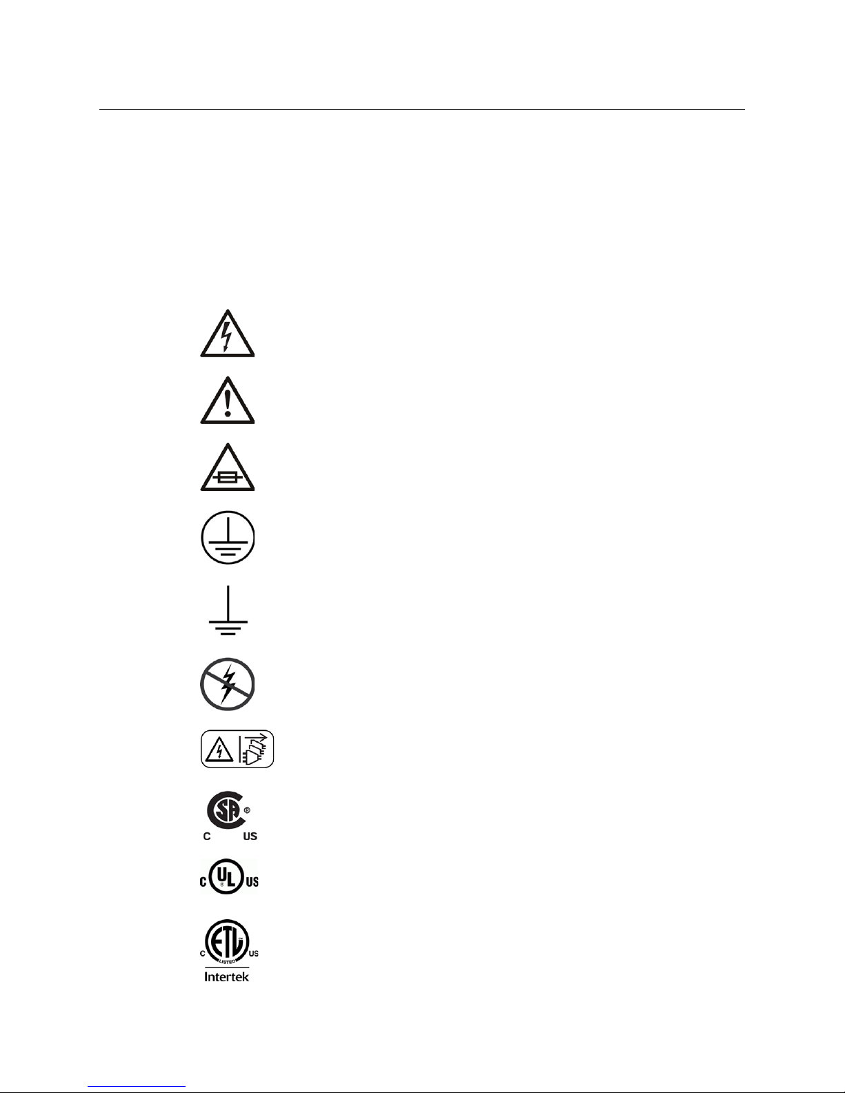
Symbols and Their Meanings
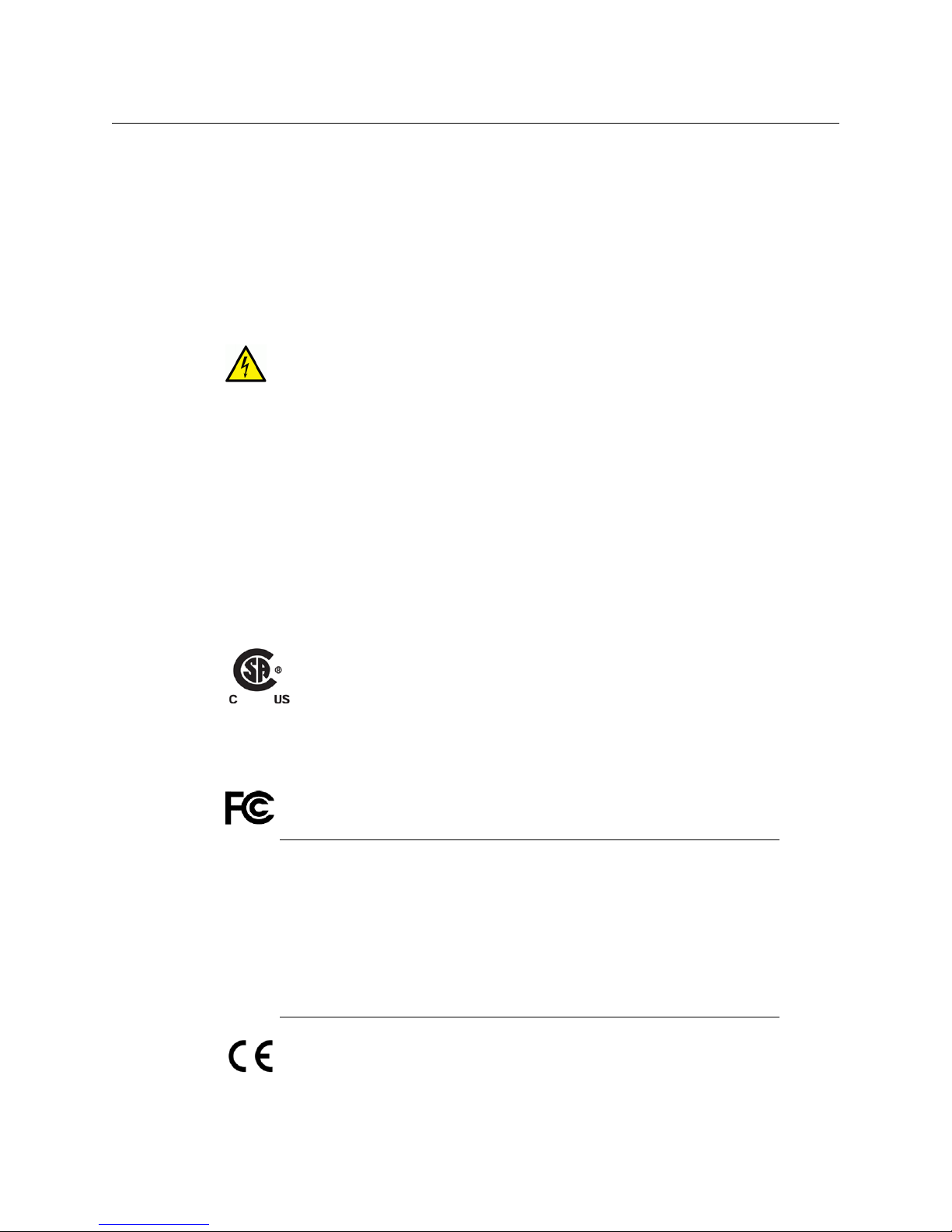
Indicates that dangerous high voltage is present within the equipment
enclosure that may be of sufficient magnitude to constitute a risk of electric
shock.
Indicates that the user, operator or service technician should refer to the product
manuals for important operating, maintenance, or service instructions.
This is a prompt to note the fuse rating when replacing fuses. The fuse
referenced in the text must be replaced with one having the ratings indicated.
Kaleido-IP X310/X110
Quick Start Guide
Identifies a protective grounding terminal which must be connected to earth
ground prior to making any other equipment connections.
Identifies an external protective grounding terminal which may be connected to
earth ground as a supplement to an internal grounding terminal.
Indicates that static sensitive components are present, which may be damaged
by electrostatic discharge. Use anti-static procedures, equipment and surfaces
during servicing.
Indicates that the equipment has more than one power supply cord, and that all
power supply cords must be disconnected before servicing to avoid electric
shock.
The presence of this symbol in or on Grass Valley equipment means that it has
been tested and certified as complying with applicable Canadian Standard
Association (CSA) regulations and recommendations for USA/Canada.
The presence of this symbol in or on Grass Valley equipment means that it has
been tested and certified as complying with applicable Underwriters Laboratory
(UL) regulations and recommendations for USA/Canada.
The presence of this symbol in or on Grass Valley equipment means that it has
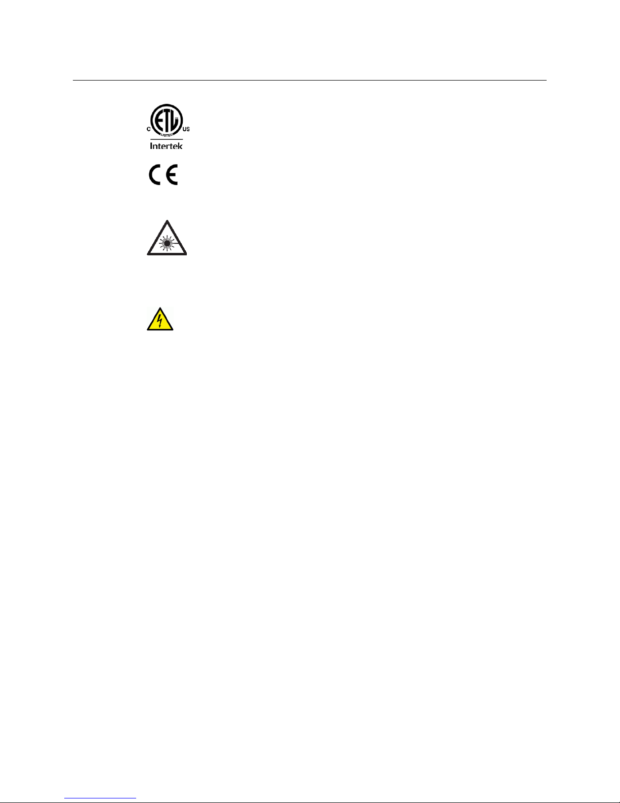
been tested and certified as complying with applicable Intertek Testing Services
regulations and recommendations for USA/Canada.
iii
Page 4
Notices
Warnings
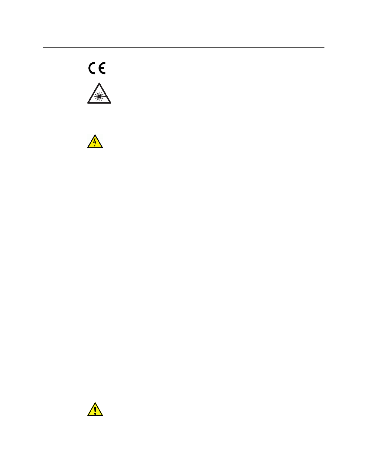
The presence of this symbol in or on Grass Valley product means that it complies
with all applicable European Union (CE) directives.
The presence of this symbol in or on Grass Valley product means that it complies
with safety of laser product applicable standards.
A warning indicates a possible hazard to personnel, which may cause injury or
death. Observe the following general warnings when using or working on this
equipment:
• Appropriately listed/certified mains supply power cords must be used for the
connection of the equipment to the mains voltage at either 120
• This product relies on the building's installation for short-circuit (over-current)
protection. Ensure that a fuse or circuit breaker for 120
phase conductors.
• Any instructions in this manual that require opening the equipment cover or enclosure
are for use by qualified service personnel only.
• Do not operate the equipment in wet or damp conditions.
• This equipment is grounded through the grounding conductor of the power cords. To
avoid electrical shock, plug the power cords into a properly wired receptacle before
connecting the equipment inputs or outputs.
• Route power cords and other cables so they are not likely to be damaged. Properly
support heavy cable bundles to avoid connector damage.
• Disconnect power before cleaning the equipment. Do not use liquid or aerosol
cleaners; use only a damp cloth.
• Dangerous voltages may exist at several points in this equipment. To avoid injury, do
not touch exposed connections and components while power is on.
• High leakage current may be present. Earth connection of product is essential before
connecting power.
• Prior to servicing, remove jewelry such as rings, watches, and other metallic objects.
• To avoid fire hazard, use only the fuse type and rating specified in the service
instructions for this product, or on the equipment.
• To avoid explosion, do not operate this equipment in an explosive atmosphere.
• Use proper lift points. Do not use door latches to lift or move equipment.
• Avoid mechanical hazards. Allow all rotating devices to come to a stop before servicing.
• Have qualified service personnel perform safety checks after any service.
V AC or 240 V AC is used on the
V AC or 240 V AC.
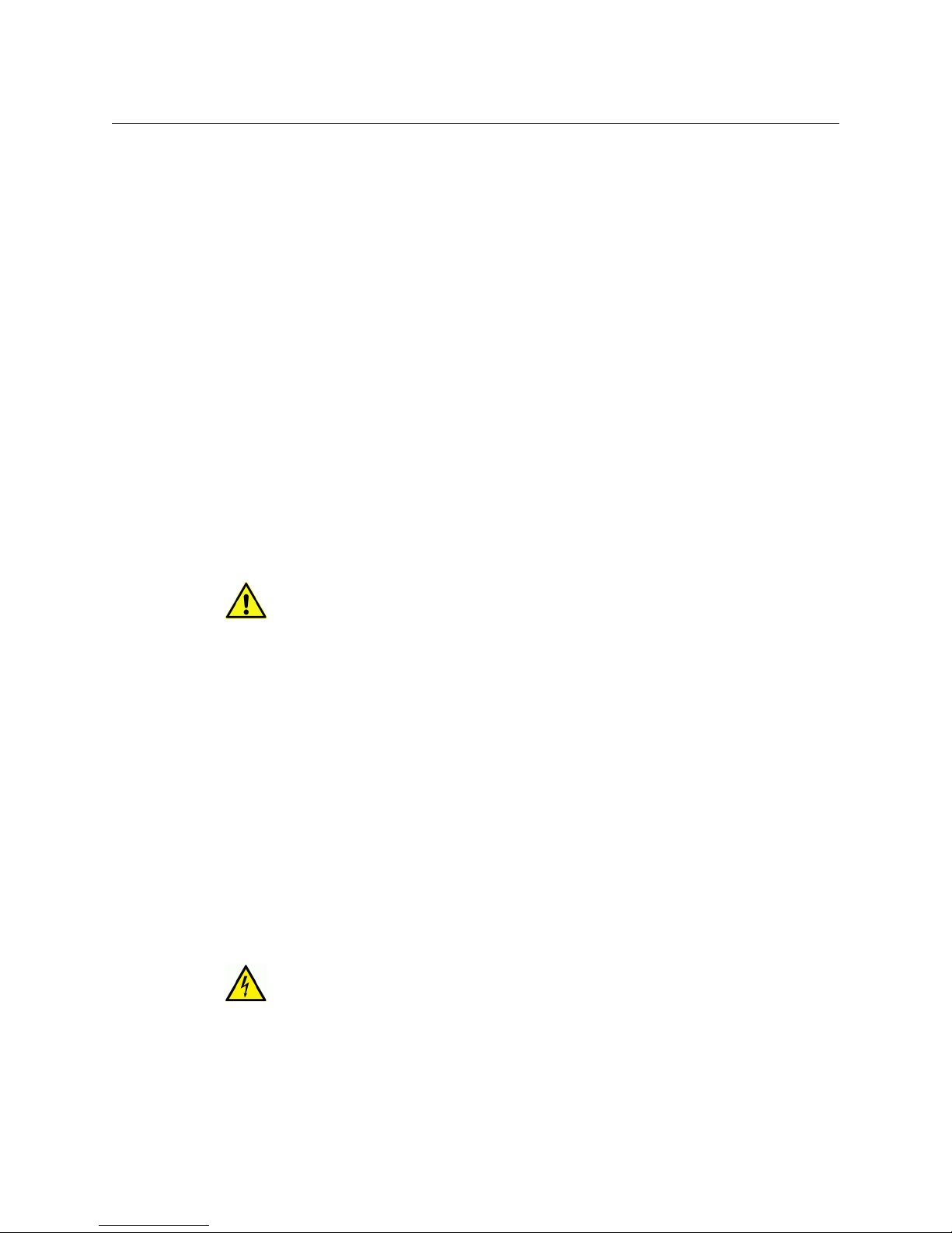
Cautions
A caution indicates a possible hazard to equipment that could result in equipment
damage. Observe the following cautions when operating or working on this
equipment:
• This equipment is meant to be installed in a restricted access location.
iv
Page 5
Kaleido-IP X310/X110
Quick Start Guide
• When installing this equipment, do not attach the power cord to building surfaces.
• Products that have no on/off switch, and use an external power supply must be
installed in proximity to a main power outlet that is easily accessible.
• Use the correct voltage setting. If this product lacks auto-ranging power supplies,
before applying power ensure that each power supply is set to match the power
source.
• Provide proper ventilation. To prevent product overheating, provide equipment
ventilation in accordance with the installation instructions.
• Do not operate with suspected equipment failure. If you suspect product damage or
equipment failure, have the equipment inspected by qualified service personnel.
• To reduce the risk of electric shock, do not perform any servicing other than that
contained in the operating instructions unless you are qualified to do so. Refer all
servicing to qualified service personnel. Servicing should be done in a static-free
environment.
• This unit may have more than one power supply cord. Disconnect all power supply
cords before servicing to avoid electric shock.
• Follow static precautions at all times when handling this equipment.
Electrostatic Discharge (ESD) Protection
Electrostatic discharge occurs when electronic components are improperly
handled and can result in intermittent failure or complete damage adversely
affecting an electrical circuit. When you remove and replace any card from a frame
always follow ESD-prevention procedures:
• Ensure that the frame is electrically connected to earth ground through the power cord
or any other means if available.
• Wear an ESD wrist strap ensuring that it makes good skin contact. Connect the
grounding clip to an unpainted surface of the chassis frame to safely ground unwanted
ESD voltages. If no wrist strap is available, ground yourself by touching the unpainted
metal part of the chassis.
• For safety, periodically check the resistance value of the antistatic strap, which should
be between
• When temporarily storing a card make sure it is placed in an ESD bag.
• Cards in an earth grounded metal frame or casing do not require any special ESD
protection.
1 and 10 megohms.
Battery Handling
This product includes a backup battery. There is a danger of explosion if the battery
is replaced incorrectly. Replace the battery only with the same or equivalent type
recommended by the manufacturer. Dispose of used batteries according to the
manufacturer’s instructions. Before disposing of your Grass Valley equipment, please
review the Disposal and Recycling Information appendix.
v
Page 6
Notices
Mesures de sécurité et avis importants
La présente section fournit des consignes de sécurité importantes pour les opérateurs et le
personnel de service. Des avertissements ou mises en garde spécifiques figurent dans le
manuel, dans les sections où ils s’appliquent. Prenez le temps de bien lire les consignes et
assurez-vous de les respecter, en particulier celles qui sont destinées à prévenir les
décharges électriques ou les blessures.
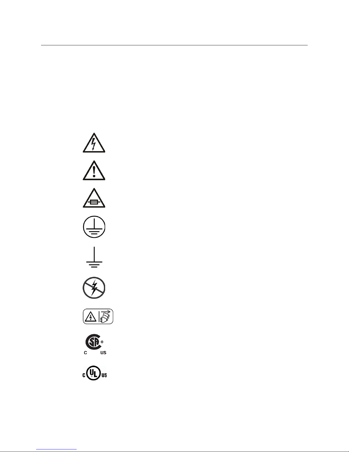
Signification des symboles utilisés
Signale la présence d’une tension élevée et dangereuse dans le boîtier de
l’équipement
décharge électrique.
Avertit l'utilisateur, l’opérateur ou le technicien de maintenance que des
instructions importantes relatives à l'utilisation et à l'entretien se trouvent dans
la documentation accompagnant l’équipement.
Invite l'utilisateur, l’opérateur ou le technicien de maintenance à prendre note du
calibre du fusible lors du remplacement de ce dernier. Le fusible auquel il est fait
référence dans le texte doit être remplacé par un fusible du même calibre.
; cette tension peut être suffisante pour constituer un risque de
Identifie une borne de mise à la terre de protection. Il faut relier cette borne à la
terre avant d’effectuer toute autre connexion à l’équipement.
Identifie une borne de mise à la terre externe qui peut être connectée en tant
que borne de mise à la terre supplémentaire.
Signale la présence de composants sensibles à l’électricité statique et qui sont
susceptibles d’être endommagés par une décharge électrostatique. Utilisez des
procédures, des équipements et des surfaces antistatiques durant les
interventions d’entretien.
Le symbole ci-contre signifie que l’appareil comporte plus d’un cordon
d'alimentation et qu’il faut débrancher tous les cordons d'alimentation avant
toute opération d’entretien, afin de prévenir les chocs électriques.
La marque C-CSA-US certifie que l’appareil visé a été testé par l'Association
canadienne de normalisation (CSA) et reconnu conforme aux exigences
applicables en matière de sécurité électrique en vigueur au Canada et aux ÉtatsUnis.
La marque C-UL-US certifie que l’appareil visé a été testé par Underwriters
Laboratory (UL) et reconnu conforme aux exigences applicables en matière de
sécurité électrique en vigueur au Canada et aux États-Unis.
vi
Page 7
Avertissements
• Un cordon d’alimentation dûment homologué doit être utilisé pour connecter
• La protection de ce produit contre les courts-circuits (surintensités) dépend de
• Dans le présent manuel, toutes les instructions qui nécessitent d’ouvrir le couvercle de
• N’utilisez pas cet appareil dans un environnement humide.
• Cet équipement est mis à la terre par le conducteur de mise à la terre des cordons
• Acheminez les cordons d’alimentation et autres câbles de façon à ce qu’ils ne risquent
• Coupez l’alimentation avant de nettoyer l’équipement. Ne pas utiliser de nettoyants
• Des tensions dangereuses peuvent exister en plusieurs points dans cet équipement.
• Avant de procéder à toute opération d’entretien ou de dépannage, enlevez tous vos
• Pour éviter tout risque d’incendie, utilisez uniquement les fusibles du type et du calibre
• Ne pas utiliser cet appareil dans une atmosphère explosive.
• Présence possible de courants de fuite. Un raccordement à la masse est indispensable
Kaleido-IP X310/X110
Quick Start Guide
La marque ETL Listed d’Intertek pour le marché Nord-Américain certifie que
l’appareil visé a été testé par Intertek et reconnu conforme aux exigences
applicables en matière de sécurité électrique en vigueur au Canada et aux ÉtatsUnis.
Le marquage CE indique que l’appareil visé est conforme aux exigences
essentielles des directives applicables de l’Union européenne en matière de
sécurité électrique, de compatibilité électromagnétique et de conformité
environnementale.
Le symbole ci-contre sur un appareil Grass Valley ou à l’intérieur de l’appareil
indique qu’il est conforme aux normes applicables en matière de sécurité laser.
Les avertissements signalent des conditions ou des pratiques susceptibles
d’occasionner des blessures graves, voire fatales. Veuillez vous familiariser avec les
avertissements d’ordre général ci-dessous
l’appareil à une tension de secteur de 120
:
V CA ou 240 V CA.
l’installation électrique du bâtiment. Assurez-vous qu'un fusible ou un disjoncteur pour
V CA ou 240 V CA est utilisé sur les conducteurs de phase.
120
l’équipement sont destinées exclusivement au personnel technique qualifié.
d’alimentation. Pour éviter les chocs électriques, branchez les cordons d’alimentation
sur une prise correctement câblée avant de brancher les entrées et sorties de
l’équipement.
pas d’être endommagés. Supportez correctement les enroulements de câbles afin de
ne pas endommager les connecteurs.
liquides ou en aérosol. Utilisez uniquement un chiffon humide.
Pour éviter toute blessure, ne touchez pas aux connexions ou aux composants exposés
lorsque l’appareil est sous tension.
bijoux (notamment vos bagues, votre montre et autres objets métalliques).
indiqués sur l’équipement ou dans la documentation qui l’accompagne.
avant la mise sous tension.
vii
Page 8

Notices
• Après tout travail d’entretien ou de réparation, faites effectuer des contrôles de sécurité
Mises en garde
• L’appareil est conçu pour être installé dans un endroit à accès restreint.
• Au moment d’installer l’équipement, ne fixez pas les cordons d’alimentation aux
• Les produits qui n'ont pas d’interrupteur marche-arrêt et qui disposent d’une source
• Si l’équipement n’est pas pourvu d’un modules d’alimentation auto-adaptables, vérifiez
• Assurez une ventilation adéquate. Pour éviter toute surchauffe du produit, assurez une
• N’utilisez pas l’équipement si vous suspectez un dysfonctionnement du produit. Faites-
• Pour réduire le risque de choc électrique, n'effectuez pas de réparations autres que
• L’appareil peut comporter plus d’un cordon d'alimentation. Afin de prévenir les chocs
• Veillez à toujours prendre les mesures de protection antistatique appropriées quand
par le personnel technique qualifié.
Les mises en garde signalent des conditions ou des pratiques susceptibles
d’endommager l’équipement. Veuillez vous familiariser avec les mises en garde ci-
dessous
surfaces intérieures de l’édifice.
d’alimentation externe doivent être installés à proximité d'une prise de courant facile
d’accès.
la configuration de chacun des modules d'alimentation avant de les mettre sous
tension.
ventilation de l’équipement conformément aux instructions d’installation.
le inspecter par un technicien qualifié.
celles qui sont décrites dans le présent manuel, sauf si vous êtes qualifié pour le faire.
Confiez les réparations à un technicien qualifié. La maintenance doit se réaliser dans un
milieu libre d’électricité statique.
électriques, débrancher tous les cordons d'alimentation avant toute opération
d’entretien.
vous manipulez l’équipement.
:
Protection contre les décharges électrostatiques (DES)
Une décharge électrostatique peut se produire lorsque des composants
électroniques ne sont pas manipulés de manière adéquate, ce qui peut entraîner
des défaillances intermittentes ou endommager irrémédiablement un circuit
électrique. Au moment de remplacer une carte dans un châssis, prenez toujours les
mesures de protection antistatique appropriées
• Assurez-vous que le châssis est relié électriquement à la terre par le cordon
d'alimentation ou tout autre moyen disponible.
• Portez un bracelet antistatique et assurez-vous qu'il est bien en contact avec la peau.
Connectez la pince de masse à une surface non peinte du châssis pour détourner à la
terre toute tension électrostatique indésirable. En l’absence de bracelet antistatique,
déchargez l’électricité statique de votre corps en touchant une surface métallique non
peinte du châssis.
viii
:
Page 9
• Pour plus de sécurité, vérifiez périodiquement la valeur de résistance du bracelet
antistatique. Elle doit se situer entre 1 et 10
• Si vous devez mettre une carte de côté, assurez-vous de la ranger dans un sac
protecteur antistatique.
• Les cartes qui sont reliées à un châssis ou boîtier métallique mis à la terre ne
nécessitent pas de protection antistatique spéciale.
Remplacement et élimination des piles
L’appareil renferme une pile. Pour réduire le risque d’explosion, vérifiez la polarité et
ne remplacez la pile que par une pile du même type, recommandée par le fabricant.
Mettez les piles usagées au rebut conformément aux directives du fabricant. Avant
de vous défaire de l’équipement, assurez-vous d’avoir lu l’appendice
Information
.
Recycling
Visit www.grassvalley.com for recycling information.
Kaleido-IP X310/X110
Quick Start Guide
mégohms.
Disposal and Recycling
Certification and Compliance
Safety Compliance
This equipment complies with the requirements of CSA/UL/IEC/EN 60950-1, 2nd
Ed. + AM1, Safety of information technology equipment.
The power cords supplied with this equipment meet the appropriate national
standards for the country of destination.
Electromagnetic Compatibility
This equipment has been tested for verification of compliance with FCC Part 15,
Subpart B requirements for class A digital devices.
Note: This equipment has been tested and found to comply with the limits
for a Class A digital device, pursuant to Part 15 of the FCC rules. These limits
are designed to provide reasonable protection against harmful interference
when the equipment is operated in a commercial environment. This
equipment generates, uses, and can radiate radio frequency energy, and, if
not installed and used in accordance with the instruction manual, may cause
harmful interference to radio communications. Operation of this equipment
in a residential area is likely to cause harmful interference in which case the
user will be required to correct the interference at his own expense.
This equipment has been tested and found to comply with the requirements of the
EMC directive 2004/108/EC
• EN 55022 Class A Radiated and conducted emissions
— Electromagnetic Compatibility:
ix
Page 10

Notices
• EN 55024 Class A Immunity
• EN 61000-3-2 Limits for harmonic current emissions
• EN 61000-3-3 Limitation of voltage fluctuations and flicker
This equipment has also been tested and found to comply with the requirements
of the EMC directive 2006/95/EC
— Low Voltage:
• EN 60950-1, 2nd edition
• IEC 60950-1, 2nd edition
• UL/CSA 60950-1, 2nd edition
• GOST R 50377-92 Certification (Russia)
• GS Certification (Germany)
x
Page 11

Table of Contents
1 Introduction . . . . . . . . . . . . . . . . . . . . . . . . . . . . . . . . . . . . . . . . . . . 1
Overview. . . . . . . . . . . . . . . . . . . . . . . . . . . . . . . . . . . . . . . . . . . . . . . . . . . . . . . . . . . . . . . . . . . . . . . . . .1
Required Materials . . . . . . . . . . . . . . . . . . . . . . . . . . . . . . . . . . . . . . . . . . . . . . . . . . . . . . . . . . . . 2
System Requirements for a Client PC . . . . . . . . . . . . . . . . . . . . . . . . . . . . . . . . . . . . . . . . . . . 3
2 Setting Up the Kaleido-IP . . . . . . . . . . . . . . . . . . . . . . . . . . . . . . . 5
Step 1: Physical Setup . . . . . . . . . . . . . . . . . . . . . . . . . . . . . . . . . . . . . . . . . . . . . . . . . . . . . . . . . . . . . 5
Setting up the Kaleido-IP Hardware . . . . . . . . . . . . . . . . . . . . . . . . . . . . . . . . . . . . . . . . . . . . 5
Cabling Diagram . . . . . . . . . . . . . . . . . . . . . . . . . . . . . . . . . . . . . . . . . . . . . . . . . . . . . . . . . . . . . . 7
Changing the Output Resolution. . . . . . . . . . . . . . . . . . . . . . . . . . . . . . . . . . . . . . . . . . . . . . . 7
Step 2: Networking Setup. . . . . . . . . . . . . . . . . . . . . . . . . . . . . . . . . . . . . . . . . . . . . . . . . . . . . . . . . . 8
Finding the Management IP Address and Application Version . . . . . . . . . . . . . . . . .13
Configuring a Client PC . . . . . . . . . . . . . . . . . . . . . . . . . . . . . . . . . . . . . . . . . . . . . . . . . . . . . . .14
Step 3: XEdit Installation . . . . . . . . . . . . . . . . . . . . . . . . . . . . . . . . . . . . . . . . . . . . . . . . . . . . . . . . . .16
Step 4: System Setup . . . . . . . . . . . . . . . . . . . . . . . . . . . . . . . . . . . . . . . . . . . . . . . . . . . . . . . . . . . . .19
Opening XEdit in Online Mode. . . . . . . . . . . . . . . . . . . . . . . . . . . . . . . . . . . . . . . . . . . . . . . .20
Configuring Transport Streams . . . . . . . . . . . . . . . . . . . . . . . . . . . . . . . . . . . . . . . . . . . . . . .20
Defining Logical Sources . . . . . . . . . . . . . . . . . . . . . . . . . . . . . . . . . . . . . . . . . . . . . . . . . . . . .25
Step 5: Testing the Monitor Wall Operation. . . . . . . . . . . . . . . . . . . . . . . . . . . . . . . . . . . . . . . .26
Using the Kaleido-RCP2 with Default Settings . . . . . . . . . . . . . . . . . . . . . . . . . . . . . . . . .26
Loading a Layout . . . . . . . . . . . . . . . . . . . . . . . . . . . . . . . . . . . . . . . . . . . . . . . . . . . . . . . . . . . . .28
3 Specifications . . . . . . . . . . . . . . . . . . . . . . . . . . . . . . . . . . . . . . . . . 29
Appendix: Disposal and Recycling Information . . . . . . . . . . . . . 33
Contact Us . . . . . . . . . . . . . . . . . . . . . . . . . . . . . . . . . . . . . . . . . . . . . . . 35
xi
Page 12

Page 13

Overview
Introduction
Welcome to the Kaleido family of multiviewers! This chapter provides information about
system requirements, and items shipped with your Kaleido-IP unit.
This Quick Start Guide is designed to help you get your Kaleido-IP X310, or Kaleido-IP X110
multiviewer up and running for the first time.
Grass Valley's Kaleido family of multiviewers ranges from quad-splits to large-scale, multiroom monitoring systems, with outstanding image quality and signal flexibility. The
Kaleido multiviewers are available in different models: the Kaleido-MX, the Kaleido-IP, the
Kaleido-X (7RU), the Kaleido-X (4RU), the Kaleido-X16, and the Kaleido-XQUAD frames, as
well as the Kaleido-Modular-X cards, and the Kaleido-Modular KMV-3901/3911 cards.
The Kaleido-IP can monitor and display HD and SD television programs distributed over IP,
across two HDTV displays. It supports MPEG-2 and H.264/AVC compressed video, and the
AAC, AC-3, DD+, MPEG-1, MPEG-2, MPEG-4 AAC LC, and MPEG-4 HE-AAC compressed audio
formats, within unencrypted DCII, DVB, or ATSC streams. The Kaleido-IP X310 supports
concurrent decoding of up to 64
of SD signals, they support concurrent decoding of up to 128
programs. The Kaleido-IP X110 supports concurrent decoding of up to 16
H.264 HD programs, and up to 48 MPEG-2 or up to 24 H.264 SD programs. The
12
Kaleido-IP X300 supports concurrent decoding of up to 24
programs, and up to 64
supports concurrent decoding of up to 8
MPEG-2 or up to 12 H.264 SD programs.
24
MPEG-2 or up to 32 H.264 SD programs. The Kaleido-IP X100
MPEG-2 or up to 32 H.264 HD video programs. In the case
MPEG-2 or up to 64 H.264
MPEG-2 or up to
MPEG-2 or up to 16 H.264 HD
MPEG-2 or up to 6 H.264 HD programs, and up to
At the heart of every multiviewer system is the Kaleido-X software, which includes the
following client applications:
• XAdmin is a Web client that your system administrator will use to manage the
multiviewer system.
• XEdit is a client application used to create layouts for the monitor wall, and to configure
the multiviewer, from your PC or laptop.
•The Router Control Software Single Bus and Matrix View applications (also part of the
iRouter Router Control Software packaged with iControl Application Servers) can be
used to control your multiviewer’s logical sources and monitor wall destinations, via
the KX Router logical router, or to control other logical routers configured within your
multiviewer system.
A Kaleido-IP multiviewer system in its default configuration includes a predefined room
and some layouts. Once you have connected your Kaleido-IP to your local management
and data networks, hooked up one or two 1920 × 1080 @ 60 Hz (HDTV) displays, and
specified transport stream information, you can start using these layouts to monitor
1
Page 14
Introduction
Required Materials
television signals distributed over IP. Consult the Kaleido-X User’s Manual (on the DVD that
shipped with your system) for instructions on how to define more rooms and layouts to suit
your specific requirements.
Required Materials
Your Kaleido-IP system package includes the following
•Kaleido-IP unit
• Installation hardware and rails, including manufacturer’s documentation for the rails
• Two 25.4 cm (10 in.) DisplayPort-to-HDMI adapter cables
• Two power cords
• DVD including the Kaleido-X User’s Manual, database samples, Quick Start guides and
hardware reference manuals for all multiviewer models
• The Kaleido-IP X310/X110 Quick Start Guide (this document)
Note: In line with our commitment to environmental preservation, only the
Quick Start Guide for your multiviewer model, and some ancillary
documents (e.g. welcome letters, warranty cards) are distributed in printed
form. All manuals and the Release Notes are available on the DVD that
shipped with your multiviewer. Refer to the Documentation section of the
Release Notes for a complete list. You can obtain the latest version of the
manuals, the Release Notes, as well as software and useful data, from the
Software and documentation section of
Grass Valley’s su ppor t por tal.
In addition to the above, you will need the following (not supplied)
• One or two displays for every Kaleido-IP unit
• Keyboard, mouse for basic Kaleido-IP configuration
• One dedicated 1000Base-T (or 100Base-T) Ethernet switch with enough ports for your
Kaleido-IP units, client PCs, and Kaleido-RCP2 devices
• Up to three more dedicated 1000Base-T (or 100Base-T) Ethernet switch for your
Kaleido-IP units to connect to high-bitrate data streams (up to five more for a Kaleido-IP
X310 with six network adapters)
• Client PC (see below for system requirements)
• Cables (to connect your multiviewers to displays, and to the networks):
Cable type Purpose
CAT-5 For Ethernet connectivity (management network, data/video
networks)
Display cables Extension modules—for example Grass Valley’s DXF-200 (par t
number DXF-200-C)—or standard DVI, HDMI, or DisplayPort cables.
DisplayPort-to-DVI adapters, if needed.
2
Page 15
System Requirements for a Client PC
A client PC or laptop meeting the following requirements is required to access the XAdmin
Web client, and the other Kaleido-X client applications.
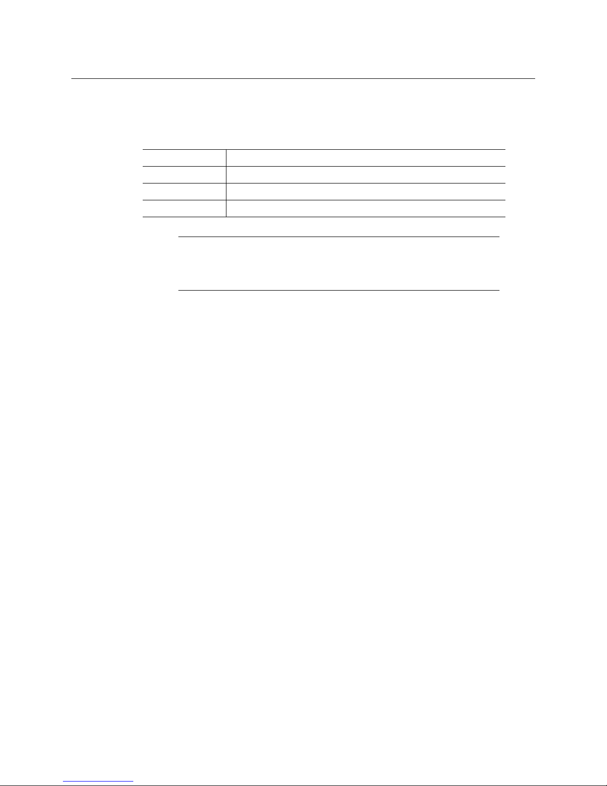
Operating system Windows XP Professional, Windows 7, Windows 8, or Windows 8.1
Processor Core 2 Duo at 2 GHz, or better
Memory At least 2 GB of RAM
Disk space At least 2 GB free
Note: The Kaleido-IP X310 and X110 multiviewers cannot be downgraded
to a Kaleido-X software version earlier than 7.30. To recover from an
unwanted downgrade, use XAdmin’s Upgrade page to upgrade your
multiviewer back to Kaleido-X version 7.30 or later.
Kaleido-IP X310/X110
Quick Start Guide
3
Page 16

Page 17

Setting Up the Kaleido-IP
This chapter will guide you through the installation of a Kaleido-IP X310, or Kaleido-IP X110
multiviewer in its default configuration.
Summary
Step 1: Physical Setup . . . . . . . . . . . . . . . . . . . . . . . . . . . . . . . . . . . . . . . . . . . . . . . . . . . . . . . . . . . . . . . . . 5
Step 2: Networking Setup . . . . . . . . . . . . . . . . . . . . . . . . . . . . . . . . . . . . . . . . . . . . . . . . . . . . . . . . . . . . . . 8
Step 3: XEdit Installation . . . . . . . . . . . . . . . . . . . . . . . . . . . . . . . . . . . . . . . . . . . . . . . . . . . . . . . . . . . . . . 16
Step 4: System Setup . . . . . . . . . . . . . . . . . . . . . . . . . . . . . . . . . . . . . . . . . . . . . . . . . . . . . . . . . . . . . . . . . 19
Step 5: Testing the Monitor Wall Operation . . . . . . . . . . . . . . . . . . . . . . . . . . . . . . . . . . . . . . . . . . . . 26
Step 1: Physical Setup
Setting up the Kaleido-IP Hardware
To set up the Kaleido-IP hardware
1 Referring to the manufacturer’s documentation shipped with your Kaleido-IP unit,
mount the unit in a standard 19-inch rack. Make sure that the unit has adequate
ventilation.
2 Connect your Kaleido-IP’s gigabit Ethernet port LAN1 to the dedicated 1000Base-T (or
100Base-T) Ethernet switch associated with your management network, and connect
LAN2 to the switch associated a data network (see
You will use the first port (gigabit LAN1) to manage your system (e.g. by using XEdit,
and XAdmin), and direct all high-bitrate data (e.g. MPEG2 streams) to the other ports
(gigabit LAN2–LAN4, or, in the case of a Kaleido-IP X310 with two optional network
adapters, LAN2–LAN6).
3 Connect the other Ethernet ports you require (if any) to the appropriate data networks.
Cabling Diagram, on page 7).
Note: To disconnect a network cable at the optional LAN5 or LAN6 data
ports, you may need to use an object (e.g., the blade of a flat screwdriver) to
reach the cable’s locking mechanism.
5
Page 18
Setting Up the Kaleido-IP
Physical Setup
4 Connect a client PC, and the Kaleido-RCP2 (if available) to the switch on LAN1. You can
also connect a mouse and a keyboard to your Kaleido-RCP2.
5 Connect one of the DisplayPort output of the multiviewer to a display that supports a
resolution of 1920
Notes
• The Kaleido-RCP2 is an optional device, and may not have been shipped
with your Kaleido-IP system. For information on this and other options for
your multiviewer system, please contact your Grass Valley sales
representative.
• You may need to upgrade your Kaleido-RCP2 devices (if available) to the
latest firmware. The update file can be found on the DVD that shipped with
your multiviewer, and on Grass Valley’s support portal. Please refer to the
Kaleido-RCP2 Guide to Installation and Operation (available on the DVD, and
from the portal), for instructions on how to determine the firmware level,
and how to perform the upgrade.
× 1080 @ 60 Hz (HDTV) (see Cabling Diagram, on page 7).
Notes
• Depending on your display type, you may use the DisplayPort-to-HDMI
that shipped with your system, or DisplayPort-to-DVI adapters (not
included).
• Although the Kaleido-IP unit has one DVI and two DisplayPort outputs,
only the two DisplayPort outputs are used.
• To disconnect a display cable at the DisplayPort outputs, you may need to
use an object (e.g., the blade of a flat screwdriver) to reach the cable’s
locking mechanism.
• If your displays are not collocated with your Kaleido-IP unit, you may
choose to employ DXF-200 transmitter/receiver devices that allow you to
install a display up to 1,000 meters (3,300 feet) from the signal source. In
this case, use a proper DisplayPort-to-HDMI cable between the Kaleido-IP
and the DXF-200-TX module. Stringing DisplayPort-to-DVI and DVI-toHDMI adapters together between the multiviewer and the DXF-200 is not
a supported configuration.
For more information on the DXF-200, refer to the DXF-200 DVI/HDMI
Optical Extension System User’s Manual (part no. M916-9900-104).
6 Connect the power cords, and then turn the power on. The power switch is located on
the front panel.
1
IMPORTANT
Should you wish to add or replace a display or AV receiver at a later time,
make sure the multiviewer is powered off, before making these changes. In
the advent that you have connected such a device while the multiviewer was
running, you must restart the multiviewer for audio monitoring to be
functional. Refer to Restarting and Shutting Down a Kaleido-IP Multiviewer, in
the Kaleido-X User’s Manual.
6
Page 19
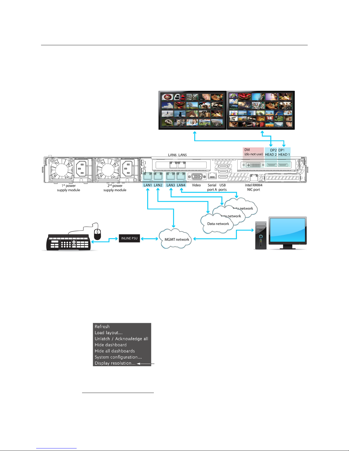
7 If you wish to use a different display resolution, see Changing the Output Resolution,
on page 7, for detailed instructions.
Cabling Diagram
Kaleido-IP X310/X110
Quick Start Guide
Cabling diagram for a Kaleido-IP X310 with two additional DATA ports (LAN5–LAN6, not connected). The Kaleido-IP
X110 rear panel is identical, except for LAN5 and LAN6, which are not available for this model.
Changing the Output Resolution
To change a display’s resolution from the monitor wall
1 Connect a mouse to one of the USB connectors of the Kaleido-IP.
2 Right-click anywhere on the monitor wall, point to Monitor Wall (if you clicked a
monitor), and then click Display resolution.
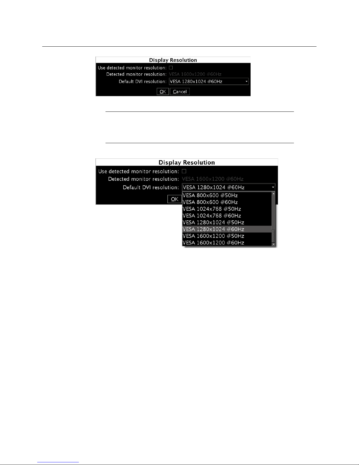
The Display Resolution window appears.
1.The Kaleido-X software does not support activating a soft shutdown from the Kaleido-IP frame’s power
button.
7
Page 20
Setting Up the Kaleido-IP
Networking Setup
3Clear the Use detected monitor resolution check box.
4 Select the desired resolution from the Default DVI resolution list.
Note: In the case of a Kaleido-IP multiviewer, the value indicated for
Detected monitor resolution in the Display Resolution window is always
“unknown” since the Kaleido-IP does not yet support automatic resolution
detection.
5Click OK.
The output resolution is adjusted accordingly.
Step 2: Networking Setup
The Kaleido-IP multiviewer must be configured with at least two IP addresses—one for the
management network (MGMT), and one for a data network (DATA)—, corresponding
network mask and gateway settings, and a system name. The Kaleido-IP X310 model may
require up to six IP addresses. In XAdmin and XEdit, a Kaleido-IP X100 or Kaleido-IP X300
with two network adapters is identified as Kaleido-IP-2. A Kaleido-IP X110, Kaleido-IP X310,
or Kaleido-IP X300 with four network adapters is identified as Kaleido-IP-4, and a Kaleido-IP
X310, or Kaleido-IP X300 with six network adapters is identified as Kaleido-IP-6.
A client PC must be configured, within the management network, to communicate with the
multiviewer (see
RCP2 units you may have ordered.
Configuring a Client PC, on page 14). You must also configure any Kaleido-
8
Page 21
Kaleido-IP X310/X110
Quick Start Guide
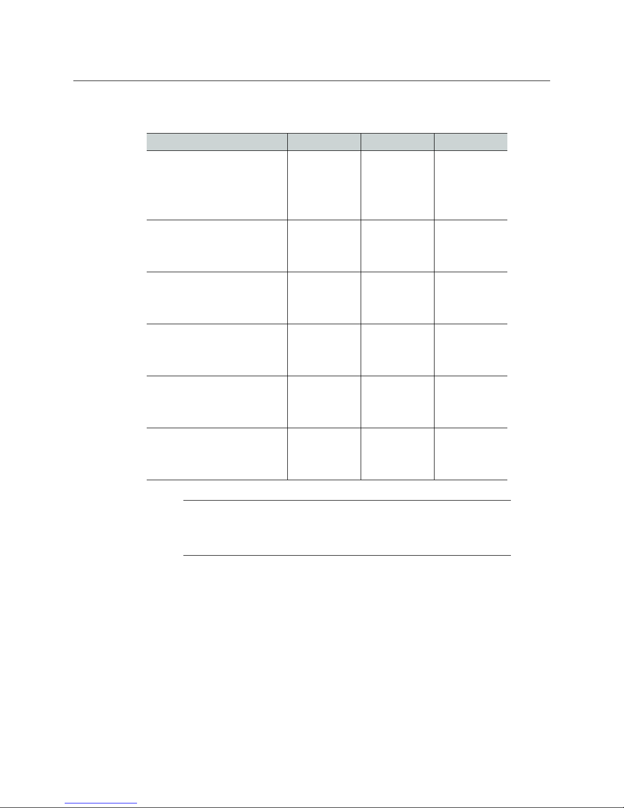
The Kaleido-IP is shipped with the following default settings.
Kaleido-IP default IP settings
Kaleido-IP-6 Kaleido-IP-4 Kaleido-IP-2
Management IP address (LAN1) 10.0.3.70 10.0.3.70 10.0.3.70
Network mask 255.255.0.0 255.255.0.0 255.255.0.0
Default gateway 10.0.0.1 10.0.0.1 10.0.0.1
Link mode Auto-negotiate Auto-negotiate Auto-negotiate
Data port 1 IP address (LAN2) 172.30.3.70 172.30.3.70 172.30.3.70
Network mask 255.255.0.0 255.255.0.0 255.255.0.0
Link mode Auto-negotiate Auto-negotiate Auto-negotiate
Data port 2 IP address (LAN3) 172.30.3.71 172.30.3.71 —
Network mask 255.255.0.0 255.255.0.0
Link mode Auto-negotiate Auto-negotiate
Data port 3 IP address (LAN4) 172.30.3.72 172.30.3.72 —
Network mask 255.255.0.0 255.255.0.0
Link mode Auto-negotiate Auto-negotiate
Data port 4 IP address (LAN5) 172.30.3.73 — —
Network mask 255.255.0.0
Link mode Auto-negotiate
Data port 5 IP address (LAN6) 172.30.3.74 — —
Network mask 255.255.0.0
Link mode Auto-negotiate
Note: If the management IP address of your Kaleido-IP has been changed
(i.e. it no longer corresponds to the as-shipped configuration), it is still
possible to determine the current management IP address setting.
Finding the Management IP Address and Application Version on page 13.
See
To change the Kaleido-IP’s management and data IP addresses
1 Configure your client PC or laptop with an IP address in the same range as the current
management IP address of the multiviewer (see
Configuring a Client PC, on page 14).
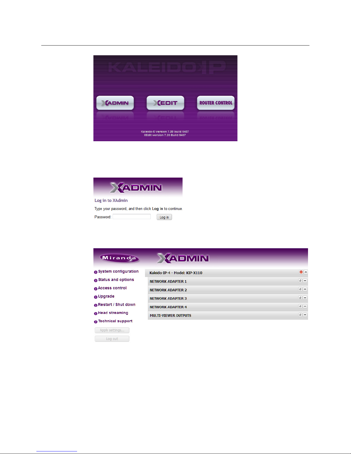
2 Open a Web browser window and type your multiviewer’s management IP address in
the address bar.
3 The multiviewer’s home page appears.
9
Page 22
Setting Up the Kaleido-IP
Networking Setup
4 Click the XAdmin button.
5 If you see a security warning, or a certificate error message, then refer to Registering
your Multiviewer's Security Credentials with your Browser, in the Kaleido-X User’s Manual.
6 If the “Log in to XAdmin” page appears, type the password, and then click Log in.
7 Internet Explorer users: If a blank page appears, then refer to Enabling the
Compatibility View in Internet Explorer 10, in the Kaleido-X User’s Manual.
The XAdmin Status and Options page appears.
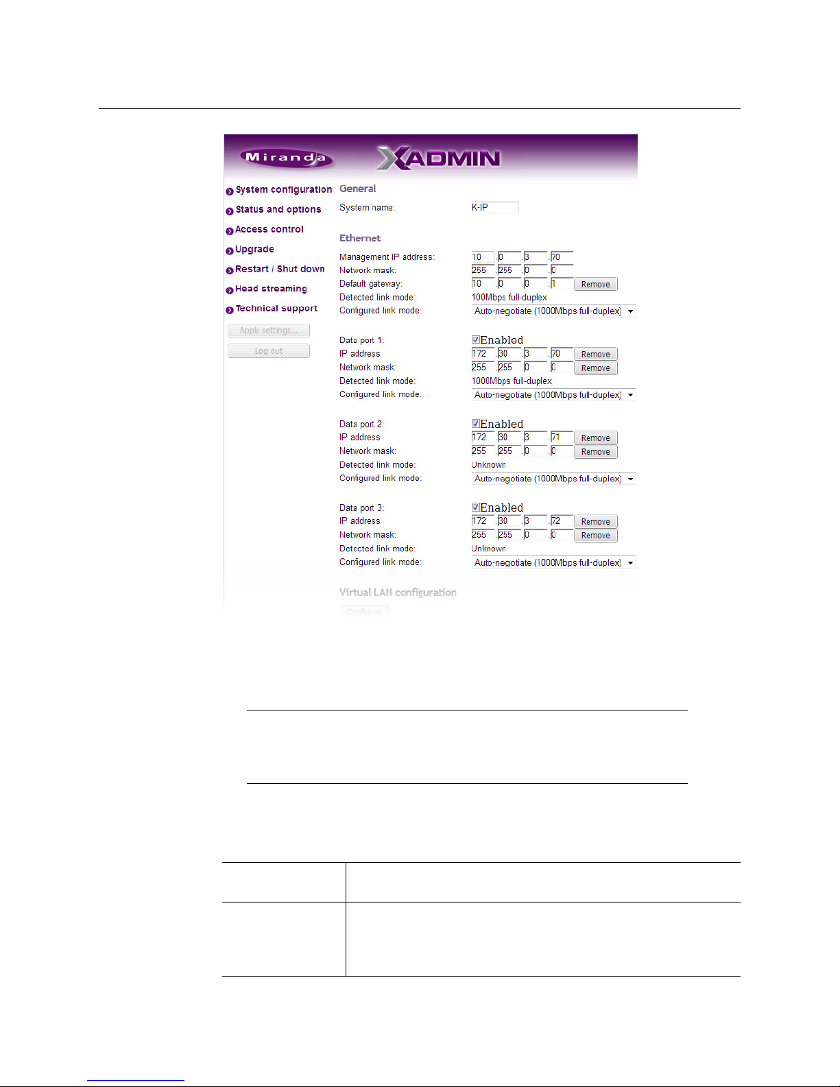
8Click System configuration, in the navigation area on the left of the page.
The System Configuration page appears, showing the current system name,
management and data IP addresses, network masks, default gateway, connectionspeed and duplex-mode settings, as well as the date and time settings.
10
Page 23
Kaleido-IP X310/X110
Quick Start Guide
9Under General, type a different name for your system if you wish.
If there are more than one multiviewer in the same network environment, it is
important to assign each a unique system name, so that you can tell them apart (for
example, when using a remote control panel such as the Kaleido-RCP2 or RCP-200).
Note: In the case of a Kaleido-IP multiviewer, the system name must
comply with RFC
to 8 characters are allowed, limited to A-Z, a-z, 0-9, and the hyphen. The
system name cannot start or end with an hyphen.
1123, because it is also used as the device’s host name. Up
10 Under Ethernet, type the appropriate IP addresses, network masks, and gateway
settings, and review the detected connection speeds and duplex modes for your
Kaleido-IP’s network adapters.
Management IP
address
Data port The IP address for a data port must be within the same range as the
Must be within the network to which the Kaleido-RCP2 units, and
the operators’ PCs or laptops are normally connected.
associated streaming devices (e.g. encoders, multiplexers).
To omit network configuration for an unused data port, clear the
corresponding Enabled check box.
11
Page 24
Setting Up the Kaleido-IP
Networking Setup
Network mask Must be set to the appropriate values, for the management and data
Default gateway If your management network is not configured with a gateway, clear
Detected link mode By default, all network adapters are set to auto-negotiate. The
networks.
the default gateway IP address.
connection speed and duplex mode will be set automatically based
on the corresponding port settings on the associated switch.
Configured link
mode
1000 Mbps full-duplex communication can only be achieved via
auto-negotiation, as required by the IEEE-802.3 standard, section
28D.5. Should your network configuration require specific speed
and duplex mode settings, select the appropriate value from the
Configured link mode list.
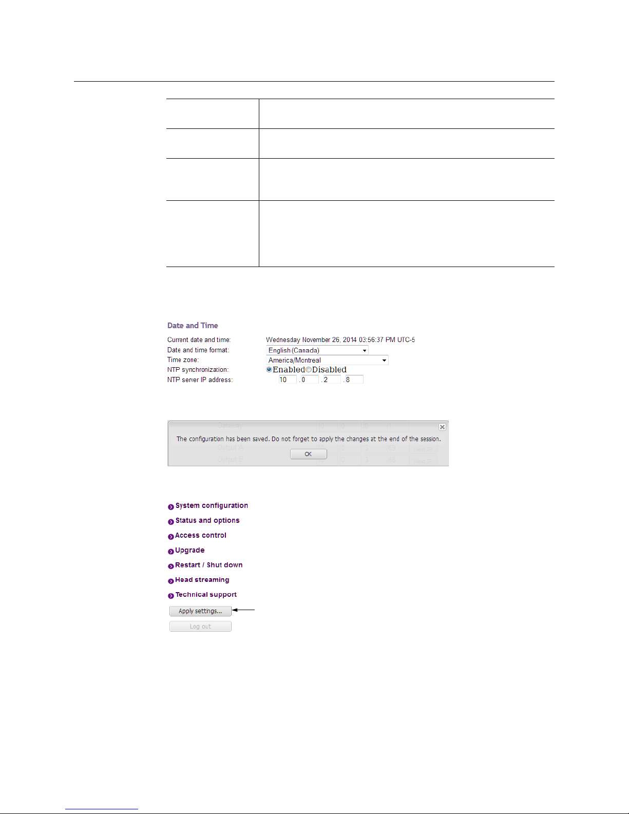
11 Under Date and Time, select the appropriate time zone and format for your location.
12 If this Kaleido-IP is meant to monitor HLS sources, enable NTP synchronization: next to
NTP synchronization, click Enabled, and then type the NTP server’s IP address.
13 Click Save.
The new settings are saved locally.
14 Click OK.
15 The Apply settings button becomes available.
16 Click Apply settings.
The multiviewer must be restarted for changes to the network configuration to take
effect. A message appears prompting you to reboot the system immediately.
12
Page 25
Kaleido-IP X310/X110
Quick Start Guide
17 Click OK.
Note: Settings cannot be applied to a multiviewer system while an
upgrade is in progress. If the multiviewer does not reboot after 10 seconds
or so, try clicking Apply settings again after a minute or two, until the
multiviewer reboots.
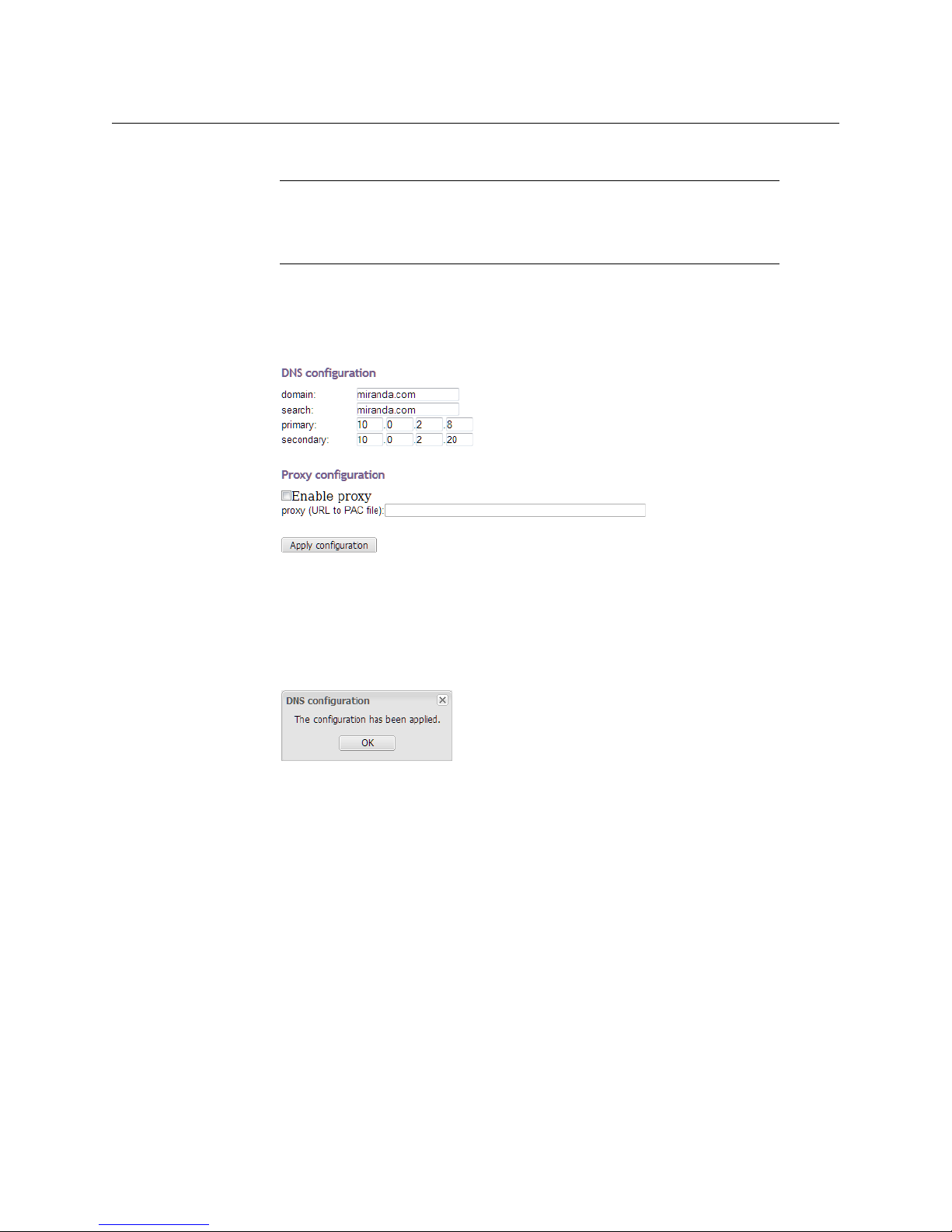
18 If this Kaleido-IP is meant to monitor HLS sources, then you must also configure access
to your facilities’ DNS, and proxy servers:
aClick Configure, under DNS and proxy configuration.
The DNS and Proxy Configuration page appears.
b Type the appropriate suffixes for your primary domain, and search domain, and the
IP addresses for the primary, and secondary DNS server.
c Select Enable proxy, and then type the URL of the appropriate proxy auto-config
(PAC) file, if required.
dClick Apply configuration.
A message appears confirming that the changes have been applied.
eClick OK to dismiss the message.
19 If this system must monitor sources from a VLAN environment, then refer to Configuring
Virtual Network Adapters on a Kaleido-IP, in the Kaleido-X User’s Manual, to add the
required virtual network adapters.
Finding the Management IP Address and Application Version
To find the management IP address and application version
1 Connect a mouse to a USB connector: either at the front of the frame, or on the rear
panel.
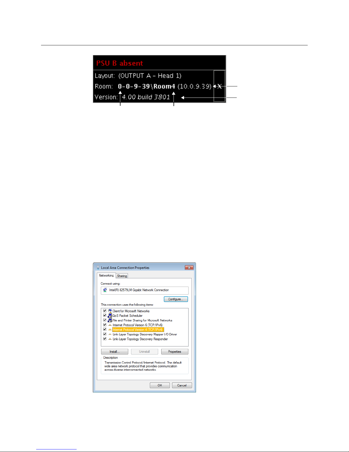
2 Right-click anywhere on the monitor wall. On the shortcut menu, point to Monitor Wall
(if you clicked a monitor), and then click Show dashboard to display the dashboard
associated with the current head. A small window appears in the bottom-right area,
revealing the management IP address and the system version. Take note of these
values.
13
Page 26
Setting Up the Kaleido-IP
Application version
Management IP address
System name Room name
Networking Setup
Configuring a Client PC
The client PC that you will use to communicate with the Kaleido-IP multiviewer (via XAdmin
and XEdit) and the multiviewer’s gigabit Ethernet port associated with the management
network must have IP addresses within the same subnet. The following procedure applies
to a typical Windows
on Windows XP, on page 15.
Changing an IP Address on Windows 7 or Windows 8
To change the IP address of a client PC that has Windows 7 or Windows 8
1 Press the Windows key on your keyboard, type “control panel” and then press Enter.
2 In the search box, type “adapter”, and then, under Network and Sharing Center, click
View network connections.
3In Network Connections, right-click the network adapter you wish to configure (e.g.,
Local Area Conn ection, or Ethernet), and then click Properties. If the system prompts you
for an administrator password or confirmation, type the password or provide
confirmation.
The Properties window for the selected network adapter opens.
7 or Windows 8 system. For Windows XP, see Changing an IP Address
4On the Networking tab, under This connection uses the following items, click
Internet Protocol Version 4 (TCP/IPv4), and then click Properties.
14
Page 27
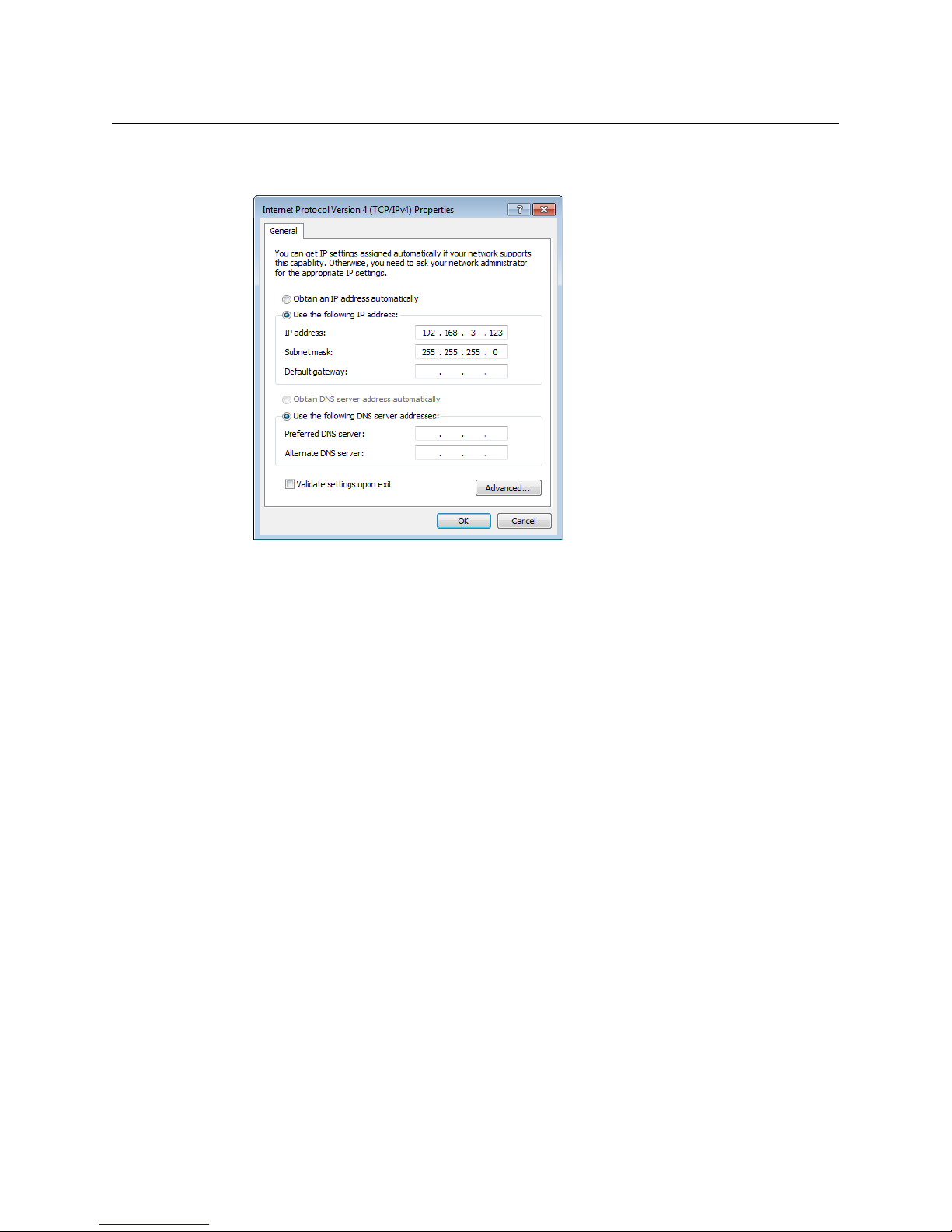
The Internet Protocol Version 4 (TCP/IPv4) Properties window opens.
5On the General tab, click Use the following IP address.
Kaleido-IP X310/X110
Quick Start Guide
6 Type an IP address in the same range as the multiviewer’s current IP address.
For example, if the multiviewer’s IP address is 192.168.3.31, then the IP address of your
client PC could be 192.168.3.123. If you are unsure, contact your network administrator.
7 Type a subnet mask in the same range as that of the multiviewer.
8Click OK.
9In Local Area Connection Properties, click Close.
Changing an IP Address on Windows XP
To change the IP address of a client PC that has Windows XP
1On the Start menu, point to Control Panel, right-click Network Connections, and then
click Open on the menu.
2In Network Connections, right-click Local Area Connection, and then click Properties
on the shortcut menu.
3In Local Area connection Properties, select Internet Protocol (TCP/IP) from the list on
the General tab, and then click Properties.
The Internet Protocol (TCP/IP) Properties window opens.
4On the General tab, click Use the following IP address.
5 Type an IP address in the same range as the multiviewer’s current IP address.
For example, if the multiviewer’s IP address is 10.0.3.70, then the IP address of your
client PC could be 10.0.3.123. If you are unsure, contact your network administrator.
6 Type a subnet mask in the same range as that of the multiviewer.
7Click OK.
8In Local Area Connection Properties, click Close.
15
Page 28
Setting Up the Kaleido-IP
XEdit Installation
Step 3: XEdit Installation
XEdit is a client application used to create layouts for the monitor wall, and to configure
your multiviewer system, from your PC or laptop. When the computer with XEdit is
connected to the multiviewer through a TCP/IP network, you can use XEdit to modify
layouts and settings directly on the multiviewer, or you can work locally on the computer
and then export your changes to the multiviewer.
To install XEdit from your multiviewer’s home page
1 From a workstation on the same subnet as the multiviewer, open a Web browser
window and type the multiviewer’s IP address in the address bar.
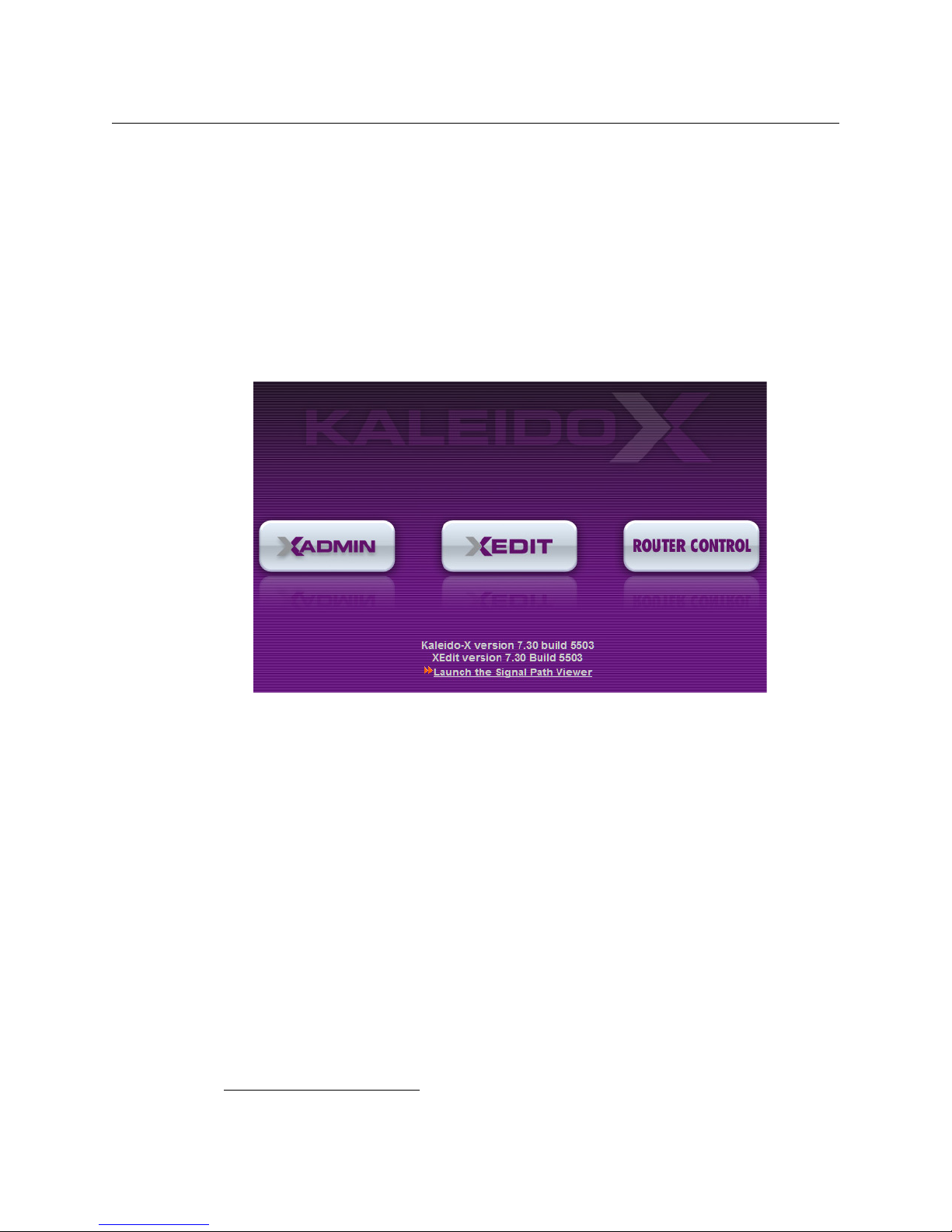
The multiviewer’s home page appears.
2Click the XEdit button.
The browser prompts you to save an executable file to your hard drive (Kaleido-
windows32-online.exe
2
). This file is an online installer, which will download XEdit and
other companion elements from your multiviewer, and install them. Some browsers
may allow you to run the file directly. Depending on your browser’s security features,
warnings may appear, which you may safely dismiss.
3 Unless your browser let you run the file (and you chose to do so), navigate to the
location were you saved the installer file and open it.
More security warnings or prompts may appear, which you may safely dismiss or
accept.
A window appears, showing the download and installation progress.
2.Installers for Linux or Mac OS X are not yet available.
16
Page 29
Kaleido-IP X310/X110
Quick Start Guide
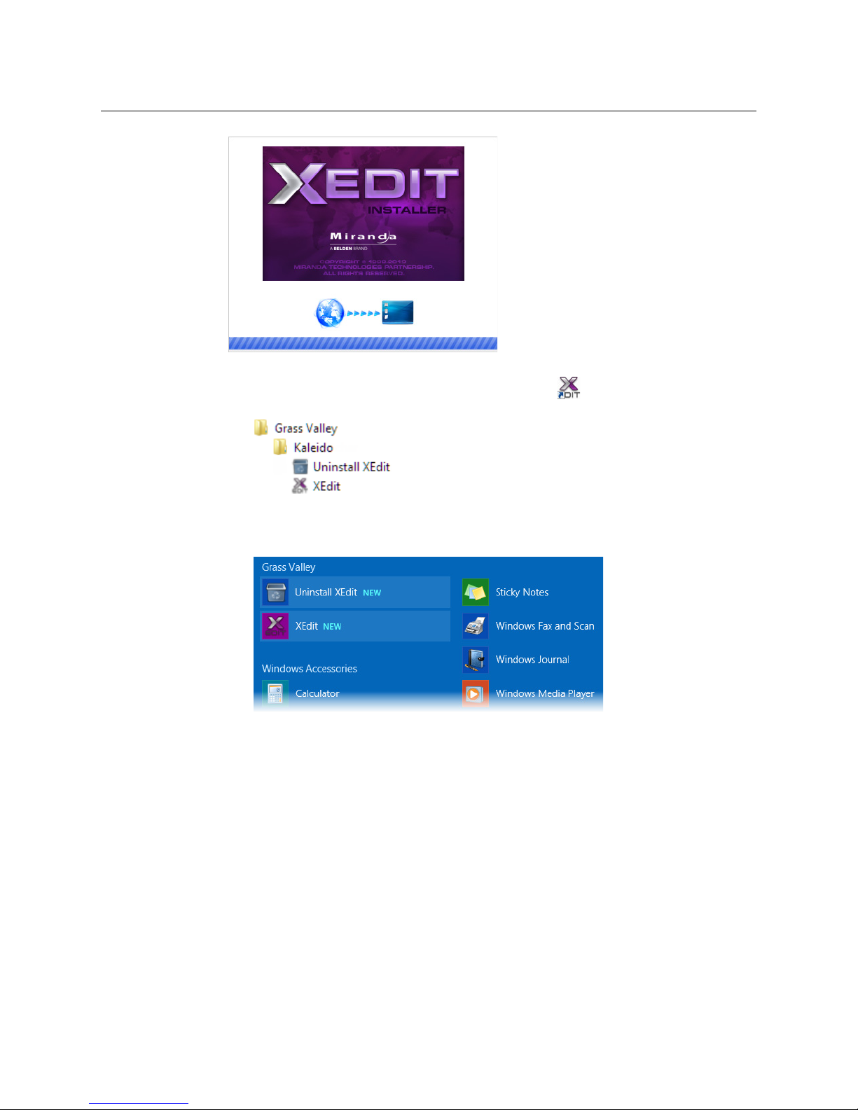
At the end of the installation process:
• If you have Windows 7, or Windows XP, shortcuts ( ) are added to your desktop
and to the Start menu (under All Programs).
• If you have Windows 8.1, or Windows 8, XEdit will appear on your desktop, in the
Apps view with all the other applications on your PC (Windows
screen (Windows
8).
8.1), or in your Start
Once the installation has completed, the XEdit startup screen appears.
17
Page 30
Setting Up the Kaleido-IP
XEdit Installation
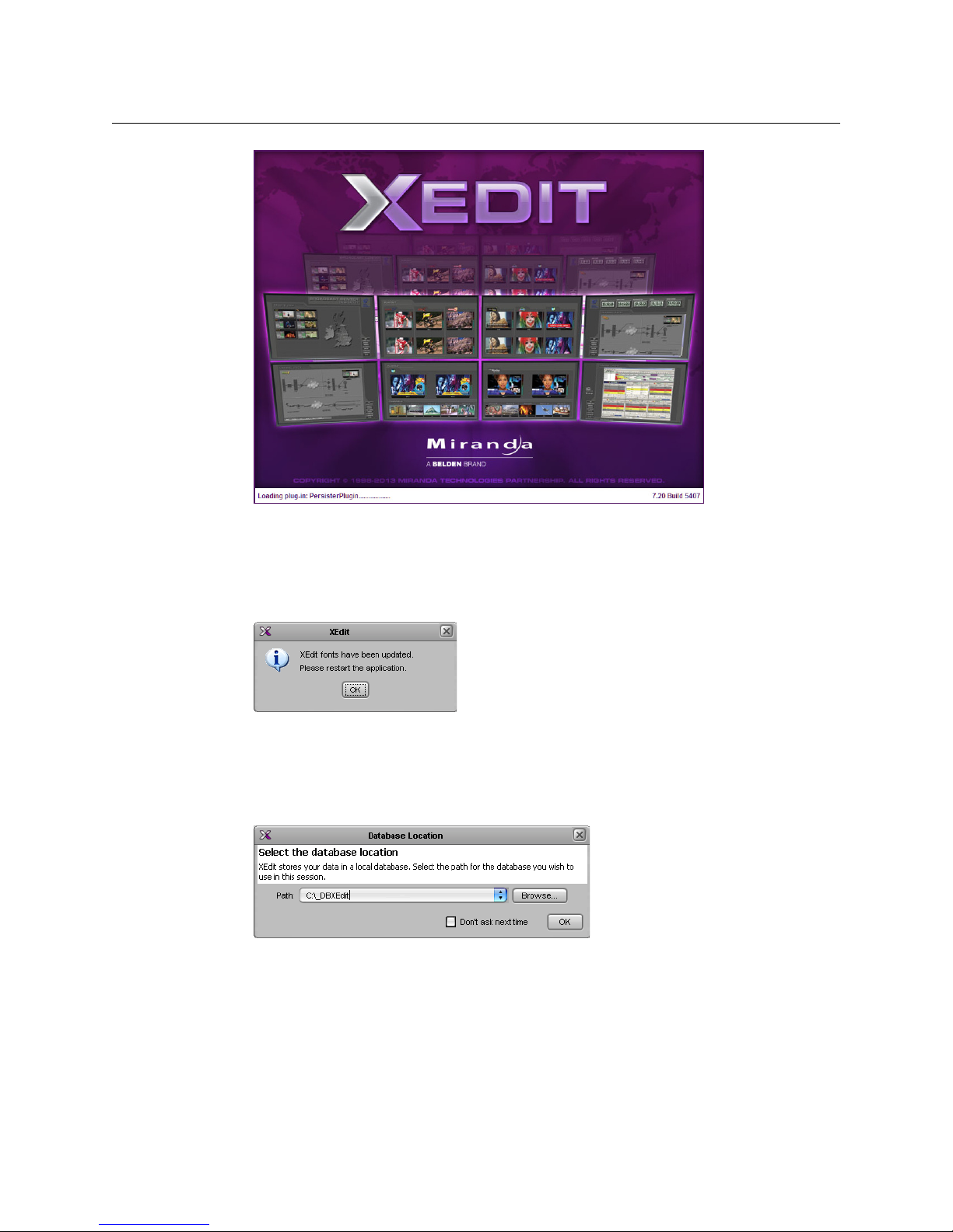
Depending on your Windows Firewall settings, a security alert may appear.
If XEdit cannot find all of the fonts it needs already on your PC or laptop, it downloads
them from the multiviewer automatically, in which case a message will appear to
confirm the font update, and instruct you to restart the application.
•Click Allow access to unblock the application.
18
•Click OK to continue, and then open XEdit again, by using the shortcut on your
desktop, in your Apps view (Windows
8.1) or Start screen (Windows 8), or from the
Start menu (Windows 7, Windows XP).
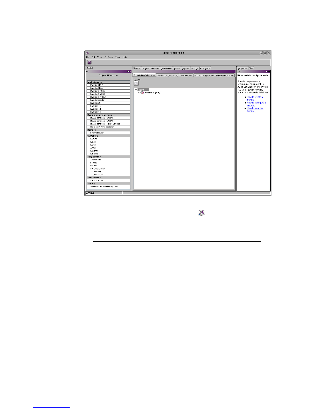
4 When prompted to specify a database, choose one from the Path list, or click Browse to
navigate to the database you wish to use as your local workspace, and then click OK.
Once the database has completed loading, XEdit’s main application window appears.
Page 31
Kaleido-IP X310/X110
Quick Start Guide
Note: Once it has been installed from the multiviewer, XEdit remains on
your PC or laptop, and can be launched from the
to your desktop, Apps view, or Start screen (see page 17), or from the Start
menu. Whenever you install a new version of the Kaleido-X software on the
multiviewer, the next time you open XEdit, your installed copy of the
application will be automatically updated from the multiviewer.
For more information about calibrating your system, configuring rooms, creating layouts,
and operating the monitor wall, refer to the Kaleido-X User’s Manual, available on the DVD
that shipped with your system, and from Grass Valley’s support portal.
Step 4: System Setup
Before you can proceed with monitor wall operation, you must use XEdit to add transport
streams to your Kaleido-IP system configuration, define logical sources based on the signals
you wish to monitor, configure monitor wall destinations (if desired), and configure the
required rooms and layouts for your purposes. Although it is possible to partly configure
your system by using XEdit in offline mode, you may initially prefer to work in online mode,
to take advantage of the predefined room and layouts that are available in the default
configuration. In any case, you must work in online mode, at least once, to obtain the list of
programs and elementary streams under each transport stream. The supported stream
types are source-specific multicast, source-filtered multicast (filtering limited to a single
source IP in include mode only), any-source multicast, and unicast. The procedures in this
section apply to the online mode.
shortcut that was added
19
Page 32

Setting Up the Kaleido-IP
System Setup
Opening XEdit in Online Mode
To open XEdit in online mode
1 From a workstation on the same subnet as the multiviewer, open a Web browser
window and enter the management IP address of your Kaleido-IP multiviewer in the
address bar.
The Kaleido-X home page appears.
2Click the XEdit button.
3 When prompted to specify a database, choose one from the Path list, or click Browse to
specify another location, and then click OK to continue.
The main application window appears.
4On the Configure menu, click Connect.
5In Connect to Multiviewer, Enter the management IP address for the Kaleido-IP you
wish to configure, and then click OK.
The selected system’s hierarchical list appears in the main pane, showing the
multiviewer type, system name and IP address, and the status bar shows the
connection status.
Configuring Transport Streams
The default configuration for a Kaleido-IP system includes eight predefined any-source
multicast (ASM) streams, under NETWORK ADAPTER 2. Before you can use these streams,
you must adjust their settings to match the actual transport streams you wish to monitor.
Depending on your monitoring purposes and Kaleido-IP model, you may also need to add
transport streams (see
Modifying the Set of Predefined Streams
To mod i fy s e tt i ngs f o r a multicast transport stream
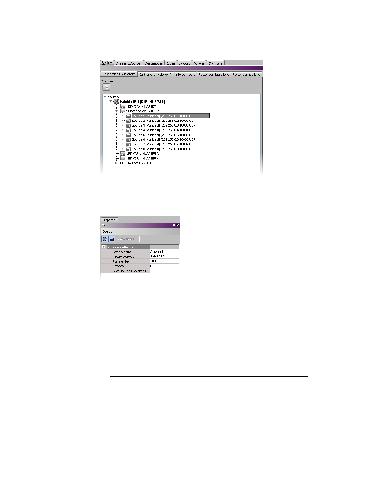
1 In the main window, click the System tab, and then click Description/Calibrations on
the second level tab bar.
2 Expand the System hierarchical list, and then navigate to the multicast transport
stream you wish to configure, under NETWORK ADAPTER 2.
Adding Stream Sources, on page 22).
20
Page 33
Kaleido-IP X310/X110
Quick Start Guide
Note: Under the network adapter elements, transport streams are listed in
alphabetical order.
The settings for the selected multicast stream appear in the Properties pane.
3 Replace the default stream name if desired, select the appropriate protocol (RTP, UDP),
and enter the multicast group IP address, and port number associated with the actual
transport stream you wish to monitor. In the case of an SSM (or SFM) stream, enter the
IP address associated with the specific source you wish to monitor in the SSM source IP
address box.
Notes
• The Kaleido-X Software supports UTF-8 encoded stream names. The only
characters, which cannot be used in a stream name are:
• Verify the protocol you selected. Registering an RTP stream as UDP instead
of RTP may result in the decoded video appearing jerky or accelerated on
the monitor wall.
@ / \ ' and ".
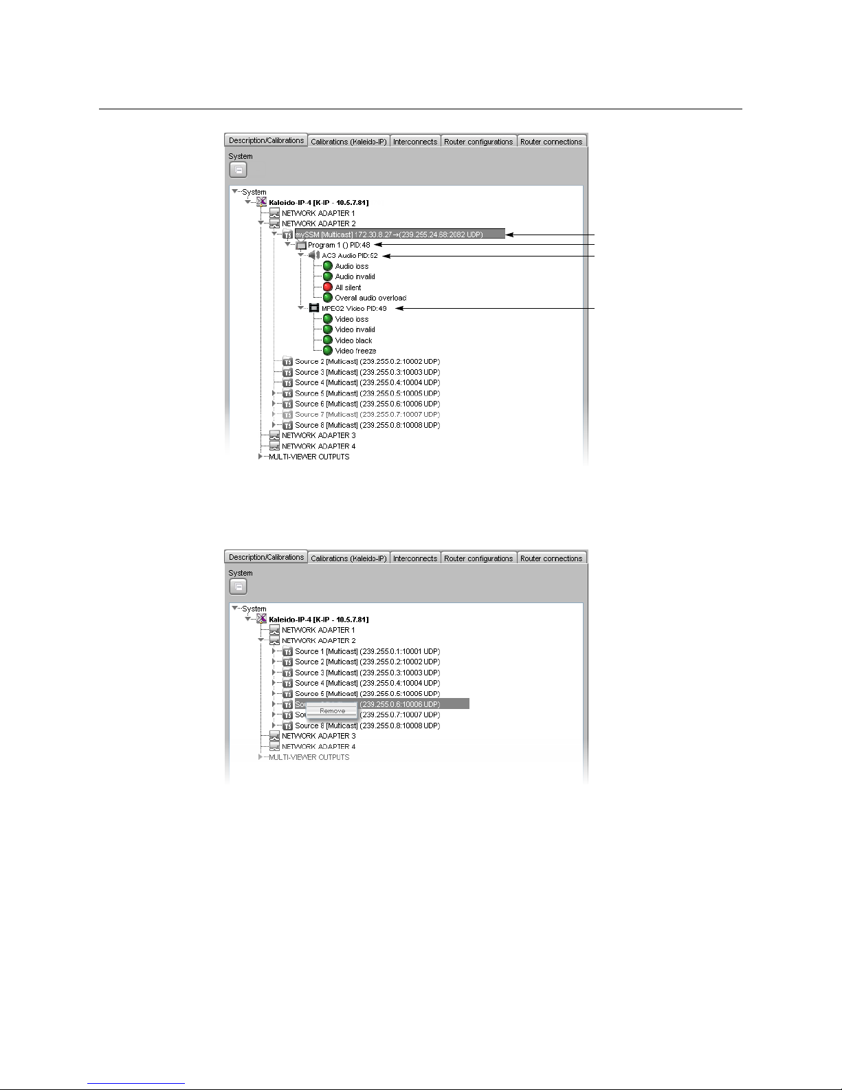
The Kaleido-IP establishes a connection with the selected stream. All programs that are
part of the stream, and the elementary streams included in these programs,
automatically appear under the transport stream element in the System list.
21
Page 34
Setting Up the Kaleido-IP
Transport stream
Program
Elementary stream (audio)
Elementary stream (video)
System Setup
4 Repeat this until you have completed the required configuration changes to match the
set of transport streams you wish to monitor.
5 If there are default transport streams left, which you will not use, right-click them, and
then click Remove.
6On the File menu, click Save. Alternatively, click the Save button on the toolbar.
Changes to the system are saved.
Adding Stream Sources
If you have connected your Kaleido-IP to more than one data network, and wish to monitor
sources from Unicast streams, or more sources from Multicast streams, then you need to
add transport streams to the basic system configuration.
Stream below, and Adding a Unicast Transport Stream, on page 24.
See Adding a Multicast Transport
Refer to Managing Transport Streams in a Kaleido-IP System Representation, in the Kaleido-X
User’s Manual, for instructions on:
22
Page 35
Kaleido-IP X310/X110
Quick Start Guide
• importing transport stream configuration information, from a spreadsheet
• adding HLS transport streams
• adding source-specific or source-filtered multicast (SSM or SFM) transport streams
• adding any-source multicast (ASM) transport streams
Adding a Multicast Transport Stream
To add a multicast transport stream
1 In the main window, click the System tab, and then click Description/Calibrations on
the second level tab bar.
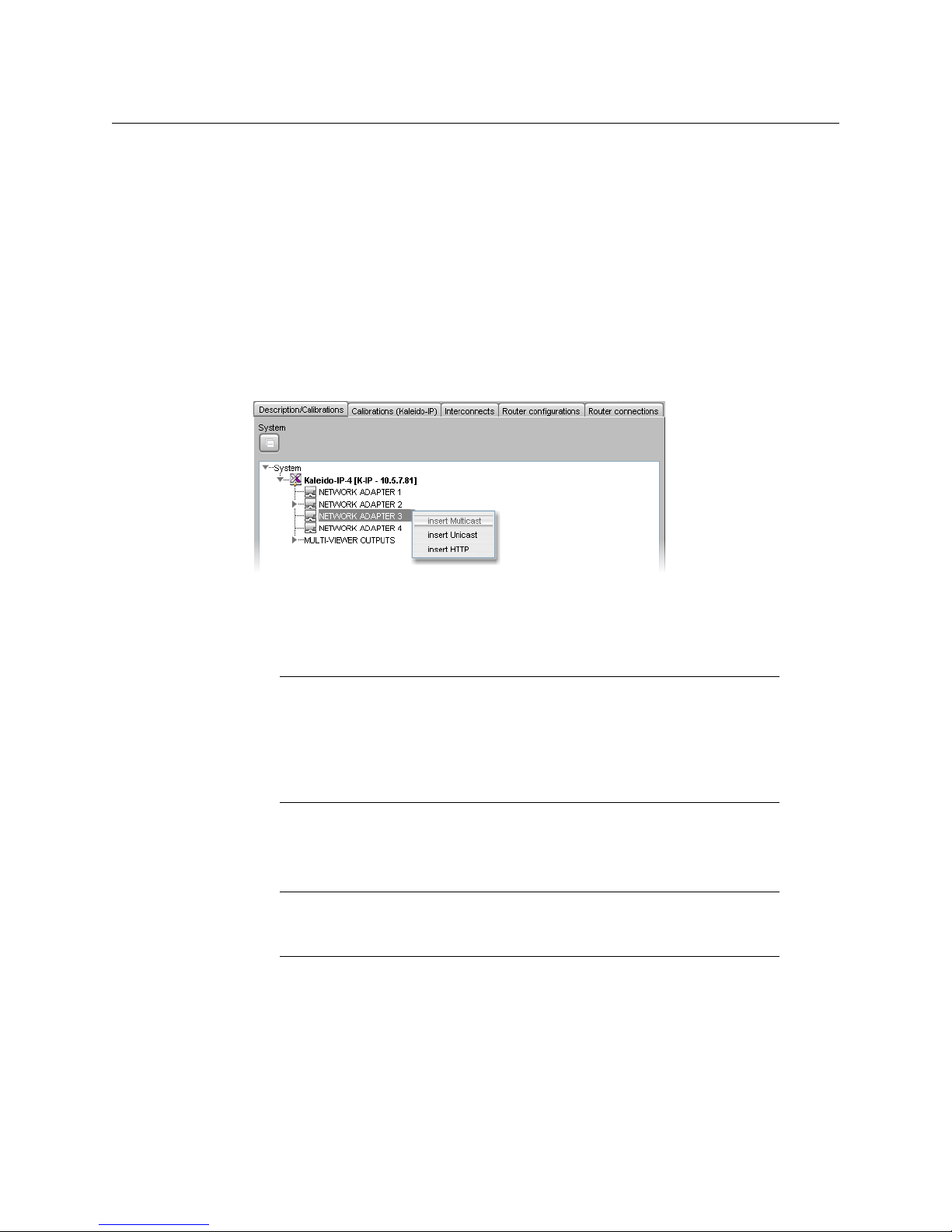
2 Expand the System hierarchical list, right-click the appropriate network adapter for the
source you wish to add, and then click insert Multicast.
The Multicast Stream Configuration window appears.
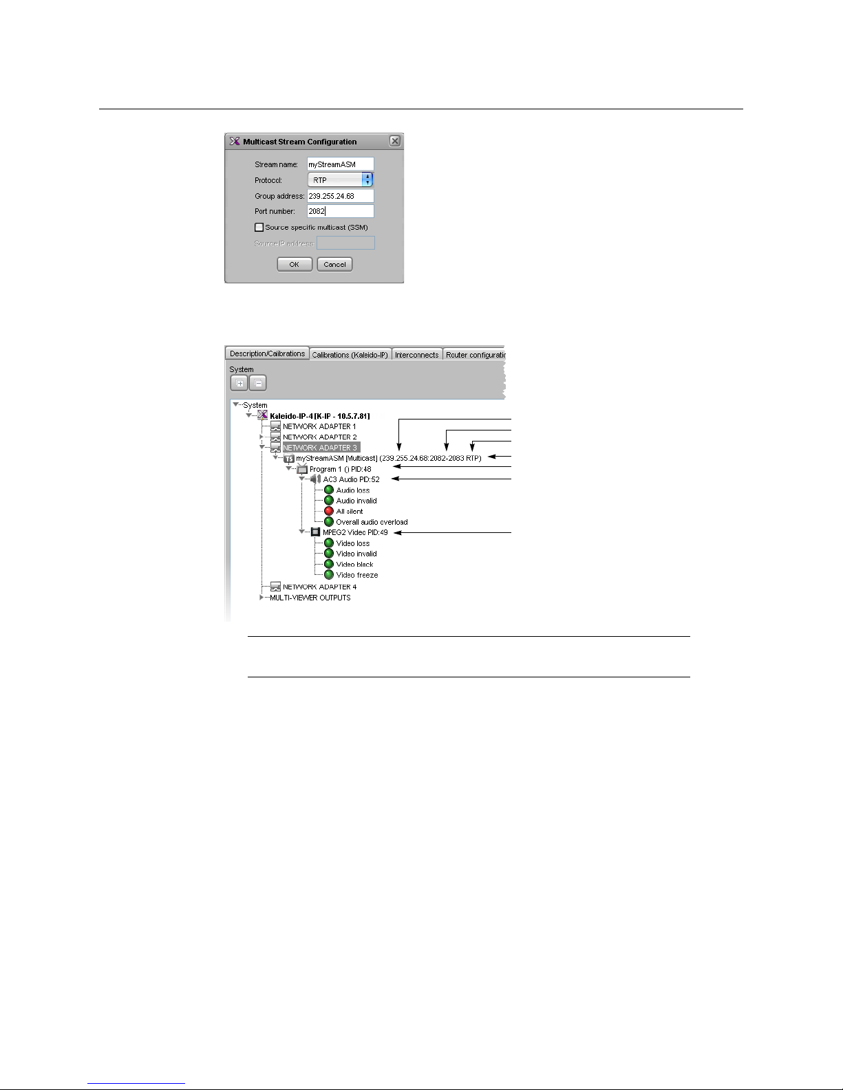
3In Multicast Stream Configuration, replace the default stream name if desired, select
the appropriate protocol (RTP, UDP), and type the multicast group address and port
number associated with the transport stream you wish to add.
Notes
• The Kaleido-X Software supports UTF-8 encoded stream names. The only
characters, which cannot be used in a stream name are:
• Verify the protocol you selected. Registering an RTP stream as UDP instead
of RTP may result in the decoded video appearing jerky or accelerated on
the monitor wall.
@ / \ ' and ".
4 In the case of an SSM (or SFM) stream, select the Source specific multicast (SSM) check
box, and then type the IP address associated with the specific source you wish to
monitor in the Source IP address box.
Note: In the case of streams that are available from the same multicast
group address and port number, you must enter the source IP address
associated with a stream before you can add the next one.
5Click OK.
23
Page 36
Setting Up the Kaleido-IP
Transport stream
Program
Elementary stream (audio)
Elementary stream (video)
Group address
Protocol
Port number (or range)
System Setup
The Kaleido-IP establishes a connection with the selected stream. All programs that are
part of the stream, and the elementary streams included in these programs,
automatically appear under the transport stream element in the System list.
24
Note: Under the network adapter elements, transport streams are listed in
alphabetical order.
6 Repeat this procedure until you have added all required multicast transport streams to
your system configuration.
7On the File menu, click Save. Alternatively, click the Save button on the toolbar.
Changes to the system are saved.
Adding a Unicast Transport Stream
To add a unicast transport stream
1 In the main window, click the System tab, and then click Description/Calibrations on
the second level tab bar.
2 Expand the System hierarchical list, right-click the appropriate network adapter for the
source you wish to add, and then click insert Unicast.
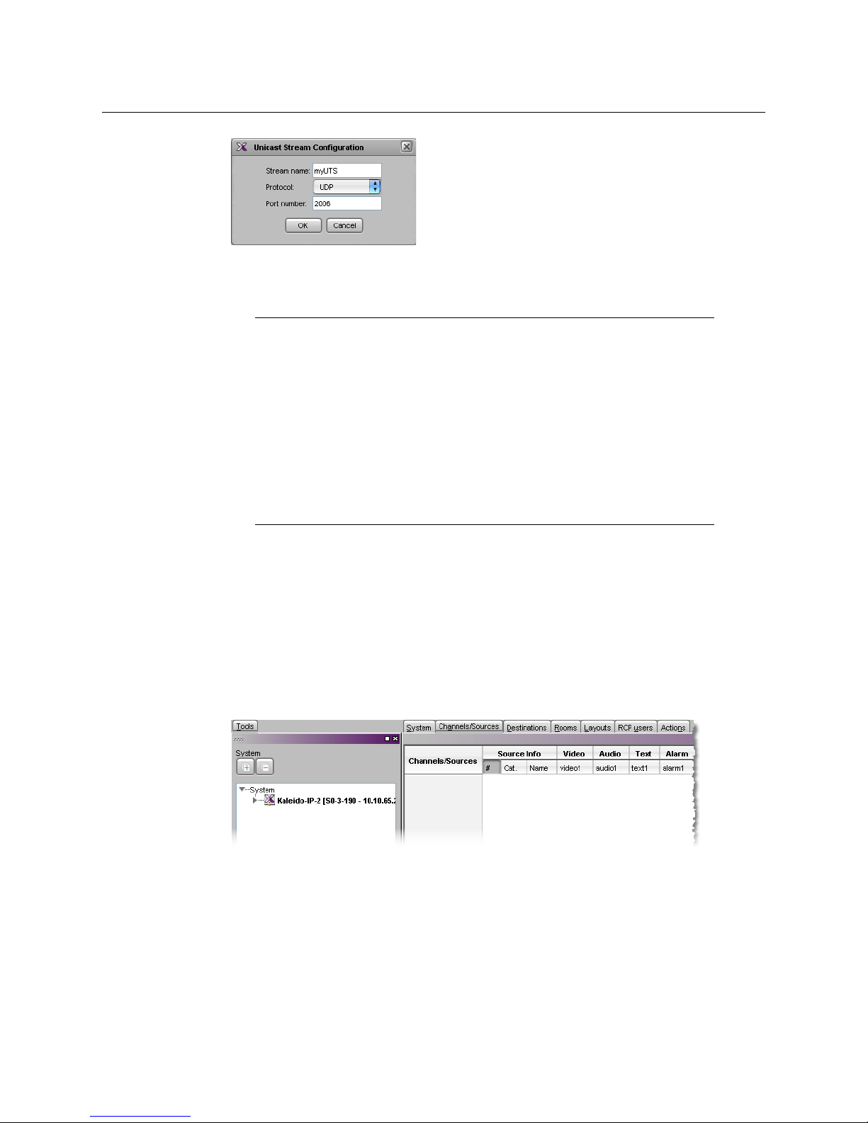
The Unicast Stream Configuration window appears.
3In Unicast Stream Configuration, replace the default stream name if desired, select the
appropriate protocol (RTP, UDP), type the port number associated with the transport
stream you wish to add, and then click OK.
Page 37
Kaleido-IP X310/X110
Quick Start Guide
The Kaleido-IP establishes a connection with the selected stream. All programs that are
part of the stream, and the elementary streams included in these programs,
automatically appear under the transport stream element in the System list.
Notes
• The Kaleido-X Software supports UTF-8 encoded stream names. The only
characters, which cannot be used in a stream name are:
• Verify the protocol you selected. Registering an RTP stream as UDP instead
of RTP may result in the decoded video appearing jerky or accelerated on
the monitor wall.
• When adding unicast transport streams do not specify consecutive port
numbers.
• Under the network adapter elements, transport streams are listed in
alphabetical order.
@ / \ ' and ".
4 Repeat this procedure until you have added all required unicast transport streams to
your system configuration.
5On the File menu, click Save. Alternatively, click the Save button on the toolbar.
Changes to the system are saved.
Defining Logical Sources
To define logical sources for a transport stream
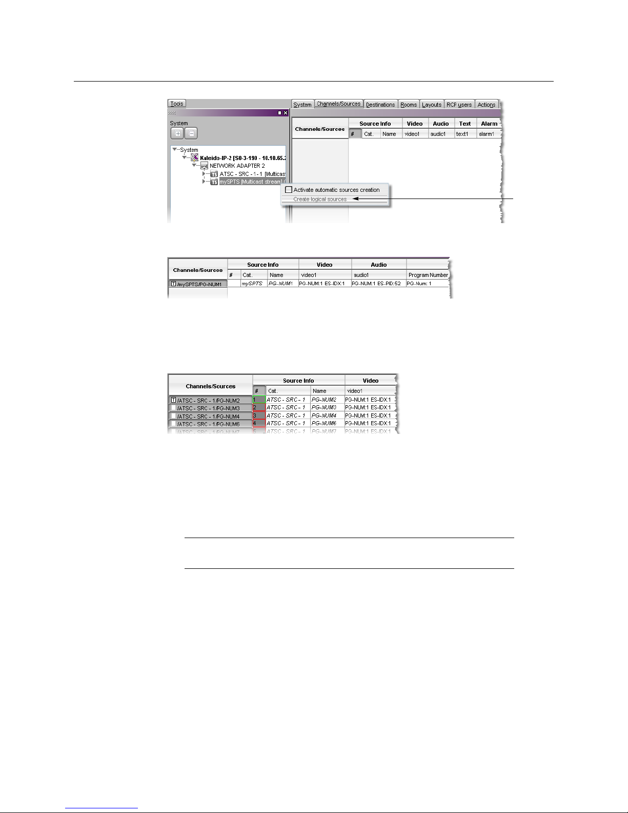
1 In the main window, click the Channels/Sources tab.
2In the To ol s pane, expand the multiviewer, and navigate to the transport stream for
which you wish to define logical sources.
3 Right-click the transport stream, and then click Create logical sources on the menu.
25
Page 38
Setting Up the Kaleido-IP
Testing the Monitor Wall Operation
Logical sources are automatically created for every program signal found in the
selected transport stream.
4 Repeat until you have added logical sources for every stream you wish to monitor.
5 If your system involves a control panel from which you will control your multiviewer as
a router, then configure source numbers for the KX Router logical router, by typing the
appropriate numbers in the first column (#) under Source info, and using the
incremental copy tool as needed.
6On the File menu, click Save. Alternatively, click the Save button on the toolbar.
Step 5: Testing the Monitor Wall Operation
Using the Kaleido-RCP2 with Default Settings
Note: The Kaleido-RCP2 unit is optional and is not included in the standard
Kaleido-IP package.
To start using the Kaleido-RCP2 with its default settings
1 Physically connect the Kaleido-RCP2 unit to the management network using an
Ethernet cable (see
By default, the Kaleido-RCP2 is configured with DHCP enabled, so it will automatically
be assigned an IP
Cabling Diagram, on page 7).
address by a DHCP server. If no DHCP server can be found, the
26
Page 39

Kaleido-IP X310/X110
Quick Start Guide
Kaleido-RCP2 will fall back to its default static IP address, subnet mask, and gateway
settings:
Default IP address 10.0.3.191
Default subnet mask 255.255.0.0
Default gateway 0.0.0.0
Notes
• If you need to operate with a fixed IP address, you must use the
Configuration menu to disable DHCP and set up the correct IP address,
Network Mask, and Gateway (see the “Enabling or Disabling DHCP” and
“Setting an IP Address, Subnet Mask and Gateway” sections in the Kaleido-
RCP2 Guide to Installation and Operation, available on the DVD that shipped
with your system.)
• To access Kaleido-X rooms located in other subnets, the Kaleido-RCP2
must be configured with the appropriate unicast IP addresses (see the
“Configuring Unicast IP Addresses” section in the Kaleido-RCP2 Guide to
Installation and Operation, available on the DVD that shipped with your
system.)
2 On the Kaleido-RCP2 unit, press the ENTER button and hold it until the ESC button
lights up.
The following message appears on the LCD display:
Configuration
ROOM SELECTION
3 Press ENTER again to obtain the room list from the Kaleido-X systems that are currently
available on the network.
The message ROOM Select followed by the name of the first room available appears on
the LCD display.
4Press the 2 key (to move up in the list) or the 8 key (to move down the list) until ROOM
is displayed.
5 Press ENTER, and then press ESC to exit the configuration menu.
6 Press the LOGIN button.
The following message appears on the LCD display:
LOGIN Position
Admin
7 Press ENTER to log on to your system as “Admin”.
A message prompting you for a password appears on the LCD display.
8 Press ENTER again (by default, there is no password).
The message “Access granted” will appear on the LCD display if the login is successful. If
a mouse is connected to the Kaleido-RCP2, then you should be able to see and move
the mouse pointer on the monitor wall.
9 Press any of the LAYOUT PRESETS buttons to load a predefined layout on the monitor
wall.
27
Page 40
Setting Up the Kaleido-IP
Testing the Monitor Wall Operation
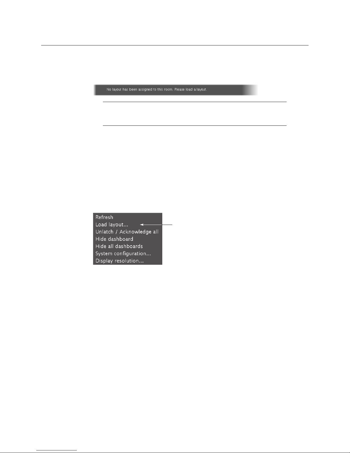
If your system was configured prior to shipment, then a layout will appear on all
displays. Otherwise, a gray screen will appear with the following message in the
middle:
“No layout has been assigned to this room. Please load a layout.”
Note: To access other layouts, press the LOAD button. To assign a layout to
a preset button, press and hold the button for more than six seconds while
the desired layout is showing on the monitor wall.
Loading a Layout
To load a layout on the monitor wall
1 Connect a mouse to the Kaleido-RCP2 (if available) and log on to the Kaleido-IP from
the Kaleido-RCP2, if you have not already done so (see
Default Settings, on page 26).
Alternatively, connect the mouse directly to one of the USB ports on the Kaleido-IP
frame.
2 Right-click anywhere on the monitor wall, point to Monitor Wall (if you clicked a
monitor), and then click Load layout on the shortcut menu.
Using the Kaleido-RCP2 with
28
A layout browser appears on the displays associated with the current room.
3 Select the layout you wish to load from the list of available layouts for this room, and
then click OK.
The selected layout appears on the room displays.
Page 41

Kaleido-IP Inputs
IP INPUTS
Kaleido-IP X310 physical 4 Gigabit Ethernet with RJ-45 connector (MGMT and DATA)
Kaleido-IP X110 physical 4 Gigabit Ethernet with RJ-45 connector (MGMT and DATA)
Transport MPEG transport streams over UDP or RTP Multicast/Unicast
Performance Up to 1 Gbps
OTHER INPUT FORMATS
ASI Densité IRD-3802 (optional)
Specifications
2 additional data Gigabit Ethernet with RJ-45 connector (optional)
IGMPv3 SSM/SFM
Multi Program Transport Streams (MPTS)
Single Program Transport Streams (SPTS)
ATSC RF Densité IRD-3811-VQ (optional)
DVB-S/S2 RF Densité IRD-3811-DVB-S2 (optional)
Set-top box EdgeVision (optional)
VIDEO DECODERS
Standard MPEG-2
H.264/AVC (ITU-T H.264)
Chroma format 4:2:0 and 4:2:2
Kaleido-IP X310
performance
Kaleido-IP X110
performance
AUDIO DECODERS
Standard MPEG-1 Layer 1
Concurrent decoding of 128 SD MPEG-2, or 64 HD MPEG-2, 64 SD
H.264, or 32 HD H.264 video programs.
Concurrent decoding of 48 SD MPEG-2, or 16 HD MPEG-2, or 24 SD
H.264 or
MPEG-1 Layer 2
MPEG-2 Layer 1
MPEG-2 Layer 2
12 HD H.264 video programs
29
Page 42

Specifications
AUDIO DECODERS (continued)
Kaleido-IP Display Outputs
The Kaleido-IP supports two independently configurable and operable display outputs.
Connectors HDMI or DisplayPort
Standard DisplayPort 1.1a
Resolution Up to 1920 × 1200 @ 60 Hz
Kaleido-IP X310 Frame
Height 43 mm (1.7 in) 1 RU
Dolby Digital AC-3 (optional)
Dolby Digital Plus (DD+) (optional)
AAC Audio (optional)
HDMI 1.3a
Width 437 mm (17.2 in)
Depth 710 mm (28 in)
Weight 12.7 kg (28 lbs)
Power supply 750 W (1+1) hot-swappable, redundant power supply, 10-4 amp
Nominal power 550 W
AC 100-240 V, 60-50 Hz
Operating temperature 10-35 °C (50-95 °F)
Max. storage humidity 90% RH non-condensing
Max. functional humidity 65% RH non-condensing
Kaleido-IP X110 Frame
Height 43 mm (1.7 in) 1 RU
Width 437 mm (17.2 in)
Depth 710 mm (28 in)
Weight 12.7 kg (28 lbs)
Power supply 750 W (1+1) hot-swappable, redundant power supply, 10-4 amp
Nominal power 170 W
AC 100-240 V, 60-50 Hz
Operating temperature 10-35 °C (50-95 °F)
30
Page 43

Max. storage humidity 90% RH non-condensing
Max. functional humidity 65% RH non-condensing
Operation and Configuration
On-screen control Kaleido-RCP2 (optional)
Source and layout
configuration
Alarms management iControl (optional)
XEdit
Display Output Extender via Fiber Optic
Device DXF-200 (optional)
Distance 1 km (3280 ft)
Fiber optic cable Multi-mode 50 or 62.5/125 SC
Connector SC
Kaleido-IP X310/X110
Quick Start Guide
Remote Video Display Output via Streaming
Device EdgeVision (optional)
31
Page 44

Page 45
Disposal and Recycling Information
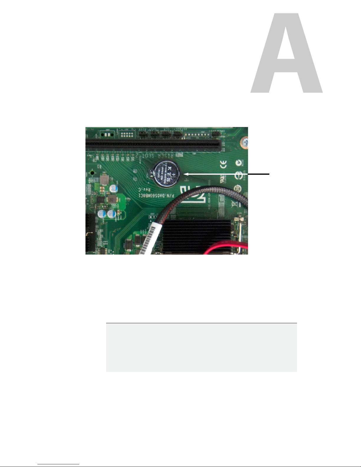
Your Grass Valley equipment comes with at least one lithium button battery (Li-MnO
located on the main printed circuit board.
Before disposing of your Grass Valley equipment, please remove the battery as follows:
1 Make sure the equipment’s AC adapters are unplugged from the power outlet.
2 Remove the protective cover from your equipment.
3 Gently remove the battery from its casing using a blunt instrument for leverage such as
a screwdriver if necessary.
4 Dispose of the battery and equipment according to your local environmental laws and
guidelines.
)
2
IMPORTANT
Be careful not to short-circuit the batteries by adhering to the appropriate
safe handling practices. Do not dispose of batteries in a fire as they may
explode. Batteries may explode if damaged or overheated. Do not dispose of
batteries as household waste. Do not dismantle, open or shred batteries.
Keep batteries out of the reach of children.
33
Page 46
Disposal and Recycling Information
IMPORTANT (continued)
The electrolyte of the batteries contains 1,2-dimethoxyethane (DME) (CAS
110-71-4, EINECS 203-794-9) above 0.1% by weight. DME is listed as a
Substance of Very High Concern (SVHC) by the regulation (EC) No 1907/2006
of the European Parliament and of the Council. It is classified as a reprotoxic
of category 2 in the European Union. Accordingly, exposure to DME may
impair fertility and may cause harm to the unborn child. DME is also classified
as harmful by inhalation.
Risk of exposure occurs only if the battery is mechanically or electrically
abused. The most likely risk is acute exposure when a cell vents. In the event
of a battery leak, do not allow battery liquid to come in contact with skin or
eyes. Seek medical help immediately in case of ingestion, inhalation, skin or
eye contact, or suspected exposure to the contents of an opened battery.
For more information about recycling, please contact Grass Valley.
34
Page 47

Grass Valley Technical Support
For technical assistance, contact our international support center, at
1-800-547-8949 (US and Canada) or +1 514 333 1772.
To obtain a local phone number for the support center nearest you, please consult the
Product Support section of Grass Valley’s Web site, at
support/contact
An online form for e-mail contact is also available from the Web site.
.
Corporate Head Office
Grass Valley
3499 Douglas-B.-Floreani
St-Laurent, Quebec H4S 2C6
Canada
Telephone: +1 514 333 1772
Fax: +1 514 333 9828
www.grassvalley.com
Contact Us
http://www.grassvalley.com/
 Loading...