

GRASS VALLEY JUPITER L - V2.1.0, JUPITER LCD - RELEASE NOTES V2.1.0, JUPITER Instruction Manual
Page 1

JUPITER
L, S, and LCD Series Control Panels
Instruction Manual
Software Version 2.1.0
071853605
OCTOBER 2010
Page 2

Affiliate with the N.V. KEMA in The Netherlands
CERTIFICATE
Certificate Number: 510040.001
The Quality System of:
Thomson Inc, and it’s wordwide Grass Valley division affiliates DBA
GRASS VALLEY
Headquarters
400 Providence Mine Rd
Nevada City, CA 95959
United States
15655 SW Greystone Ct.
Beaverton, OR 97006
United States
10 Presidential Way
Suite 300
Woburn, MA 01801
United States
Kapittelweg 10
4827 HG Breda
The Nederlands
7140 Baymeadows Way
Ste 101
Jacksonville, FL 32256
United States
2300 So. Decker Lake Blvd.
Salt Lake City, UT 84119
United States
Rue du Clos Courtel
CS 31719
35517 Cesson-Sevigné Cedex
France
1 rue de l’Hautil
Z.I. des Boutries BP 150
78702 Conflans-Sainte
Honorine Cedex
France
Technopole Brest-Iroise
Site de la Pointe du Diable
CS 73808
29238 Brest Cedex 3
France
40 Rue de Bray
2 Rue des Landelles
35510 Cesson Sevigné
France
Spinnereistrasse 5
CH-5300 Turgi
Switzerland
Brunnenweg 9
D-64331 Weiterstadt
Germany
Carl-Benz-Strasse 6-8
67105 Schifferstadt
Germany
Including its implementation, meets the requirements of the standard:
ISO 9001:2008
Scope:
The design, manufacture and support of video and audio hardware and software products and
related systems
.
This Certificate is valid until: June 14, 2012
This Certificate is valid as of: June 14, 2009
Certified for the first time: June 14, 2000
H. Pierre Sallé
President
KEMA-Registered Quality
The method of operation for quality certification is defined in the KEMA General Terms
And Conditions For Quality And Environmental Management Systems Certifications.
Integral publication of this certificate is allowed.
KEMA-Registered Quality, Inc.
4377 County Line Road
Chalfont, PA 18914
Ph: (215)997-4519
Fax: (215)997-3809
CRT 001 073004
ccredited By:
ANAB
A
Page 3

JUPITER
L, S, and LCD Series Control Panels
Instruction Manual
Software Version 2.1.0
071853605
OCTOBER 2010
Page 4
Contacting Grass Valley
International
Support Centers
Local Support
Centers
(available
during normal
business hours)
France
24 x 7
Australia and New Zealand: +61 1300 721 495 Central/South America: +55 11 5509 3443
Middle East: +971 4 299 64 40 Near East and Africa: +800 8080 2020 or +33 1 48 25 20 20
Europe
+800 8080 2020 or +33 1 48 25 20 20
Hong Kong, Taiwan, Korea, Macau: +852 2531 3058 Indian Subcontinent: +91 22 24933476
Asia
Southeast Asia/Malaysia: +603 7805 3884 Southeast Asia/Singapore: +65 6379 1313
China: +861 0660 159 450 Japan: +81 3 5484 6868
Belarus, Russia, Tadzikistan, Ukraine, Uzbekistan: +7 095 2580924 225 Switzerland: +41 1 487 80 02
S. Europe/Italy-Roma: +39 06 87 20 35 28 -Milan: +39 02 48 41 46 58 S. Europe/Spain: +34 91 512 03 50
Benelux/Belgium: +32 (0) 2 334 90 30 Benelux/Netherlands: +31 (0) 35 62 38 42 1 N. Europe: +45 45 96 88 70
Germany, Austria, Eastern Europe: +49 6150 104 444 UK, Ireland, Israel: +44 118 923 0499
Copyright © Grass Valley, Inc. All rights reserved.
This product may be covered by one or more U.S. and foreign patents.
United States/Canada
24 x 7
+1 800 547 8949 or +1 530 478 4148
Grass Valley Web Site
The www.grassvalley.com web site offers the following:
Online User Documentation — Current versions of product catalogs, brochures,
data sheets, ordering guides, planning guides, manuals, and release notes
in .pdf format can be downloaded.
FAQ Database — Solutions to problems and troubleshooting efforts can be
found by searching our Frequently Asked Questions (FAQ) database.
Software Downloads — Download software updates, drivers, and patches.
4 JUPITER L-S and LCD Series Control Panel Instruction Manual
Page 5

Contents
Preface. . . . . . . . . . . . . . . . . . . . . . . . . . . . . . . . . . . . . . . . . . . . . . . . . . . . . . . . . . . . . . . . . . . . 13
Safety Summary. . . . . . . . . . . . . . . . . . . . . . . . . . . . . . . . . . . . . . . . . . . . . . . . . . . . . . . . . 15
Regulatory Notices . . . . . . . . . . . . . . . . . . . . . . . . . . . . . . . . . . . . . . . . . . . . . . . . . . . . . . 27
About This Manual . . . . . . . . . . . . . . . . . . . . . . . . . . . . . . . . . . . . . . . . . . . . . . . . . . . . 13
Additional Documentation . . . . . . . . . . . . . . . . . . . . . . . . . . . . . . . . . . . . . . . . . . . 13
Safety Terms and Symbols. . . . . . . . . . . . . . . . . . . . . . . . . . . . . . . . . . . . . . . . . . . . . . 15
Terms in This Manual. . . . . . . . . . . . . . . . . . . . . . . . . . . . . . . . . . . . . . . . . . . . . . . . 15
Terms on the Product . . . . . . . . . . . . . . . . . . . . . . . . . . . . . . . . . . . . . . . . . . . . . . . . 15
Symbols on the Product . . . . . . . . . . . . . . . . . . . . . . . . . . . . . . . . . . . . . . . . . . . . . . 16
Warnings . . . . . . . . . . . . . . . . . . . . . . . . . . . . . . . . . . . . . . . . . . . . . . . . . . . . . . . . . . . . 16
Cautions . . . . . . . . . . . . . . . . . . . . . . . . . . . . . . . . . . . . . . . . . . . . . . . . . . . . . . . . . . . . . 17
Certifications and Compliances . . . . . . . . . . . . . . . . . . . . . . . . . . . . . . . . . . . . . . . . . 27
FCC Emission Control . . . . . . . . . . . . . . . . . . . . . . . . . . . . . . . . . . . . . . . . . . . . . . . 27
Canadian EMC Notice of Compliance . . . . . . . . . . . . . . . . . . . . . . . . . . . . . . . . . . 27
EN55022 Class A Warning . . . . . . . . . . . . . . . . . . . . . . . . . . . . . . . . . . . . . . . . . . . . 27
Canadian Certified Power Cords . . . . . . . . . . . . . . . . . . . . . . . . . . . . . . . . . . . . . . 28
Canadian Certified AC Adapter . . . . . . . . . . . . . . . . . . . . . . . . . . . . . . . . . . . . . . . 28
Safety and EMI Certification . . . . . . . . . . . . . . . . . . . . . . . . . . . . . . . . . . . . . . . . . . 28
Section 1 — L-S series Introduction . . . . . . . . . . . . . . . . . . . . . . . . . . . . . . . . . . . 31
Overview . . . . . . . . . . . . . . . . . . . . . . . . . . . . . . . . . . . . . . . . . . . . . . . . . . . . . . . . . . . . 31
L Series Control Panel Features . . . . . . . . . . . . . . . . . . . . . . . . . . . . . . . . . . . . . . . . . 32
L32 . . . . . . . . . . . . . . . . . . . . . . . . . . . . . . . . . . . . . . . . . . . . . . . . . . . . . . . . . . . . . . . . 32
L64 . . . . . . . . . . . . . . . . . . . . . . . . . . . . . . . . . . . . . . . . . . . . . . . . . . . . . . . . . . . . . . . . 32
LD4. . . . . . . . . . . . . . . . . . . . . . . . . . . . . . . . . . . . . . . . . . . . . . . . . . . . . . . . . . . . . . . . 33
LD16. . . . . . . . . . . . . . . . . . . . . . . . . . . . . . . . . . . . . . . . . . . . . . . . . . . . . . . . . . . . . . . 33
S Series Control Panel Features. . . . . . . . . . . . . . . . . . . . . . . . . . . . . . . . . . . . . . . . . . 35
S25/S50 . . . . . . . . . . . . . . . . . . . . . . . . . . . . . . . . . . . . . . . . . . . . . . . . . . . . . . . . . . . . 35
S100 . . . . . . . . . . . . . . . . . . . . . . . . . . . . . . . . . . . . . . . . . . . . . . . . . . . . . . . . . . . . . . . 35
SXY. . . . . . . . . . . . . . . . . . . . . . . . . . . . . . . . . . . . . . . . . . . . . . . . . . . . . . . . . . . . . . . . 36
Specifications . . . . . . . . . . . . . . . . . . . . . . . . . . . . . . . . . . . . . . . . . . . . . . . . . . . . . . . . . 37
Ordering Information. . . . . . . . . . . . . . . . . . . . . . . . . . . . . . . . . . . . . . . . . . . . . . . . . . 38
Section 2 — Hardware Installation. . . . . . . . . . . . . . . . . . . . . . . . . . . . . . . . . . . . . 41
Rack Mounting . . . . . . . . . . . . . . . . . . . . . . . . . . . . . . . . . . . . . . . . . . . . . . . . . . . . . . . 41
Power Supplies . . . . . . . . . . . . . . . . . . . . . . . . . . . . . . . . . . . . . . . . . . . . . . . . . . . . . . . 41
Network Wiring . . . . . . . . . . . . . . . . . . . . . . . . . . . . . . . . . . . . . . . . . . . . . . . . . . . . . . 42
Button Labels . . . . . . . . . . . . . . . . . . . . . . . . . . . . . . . . . . . . . . . . . . . . . . . . . . . . . . . . . 43
L32/L64/S100 Panels . . . . . . . . . . . . . . . . . . . . . . . . . . . . . . . . . . . . . . . . . . . . . . . . 43
LD4 Panels . . . . . . . . . . . . . . . . . . . . . . . . . . . . . . . . . . . . . . . . . . . . . . . . . . . . . . . . . 44
LD16 Panels . . . . . . . . . . . . . . . . . . . . . . . . . . . . . . . . . . . . . . . . . . . . . . . . . . . . . . . . 44
S25/S50 . . . . . . . . . . . . . . . . . . . . . . . . . . . . . . . . . . . . . . . . . . . . . . . . . . . . . . . . . . . . 45
JUPITER L-S and LCD Series Control Panel Instruction Manual 5
Page 6

Contents
SXY Panels . . . . . . . . . . . . . . . . . . . . . . . . . . . . . . . . . . . . . . . . . . . . . . . . . . . . . . . . . 45
Button Configuration Overview. . . . . . . . . . . . . . . . . . . . . . . . . . . . . . . . . . . . . . . 45
Source Button Configuration. . . . . . . . . . . . . . . . . . . . . . . . . . . . . . . . . . . . . . . . 45
Category Button Configuration . . . . . . . . . . . . . . . . . . . . . . . . . . . . . . . . . . . . . 46
Level Button Configuration. . . . . . . . . . . . . . . . . . . . . . . . . . . . . . . . . . . . . . . . . 46
Keycap Transparency Labels . . . . . . . . . . . . . . . . . . . . . . . . . . . . . . . . . . . . . . . . . 46
Section 3 — Software Installation & IP Addresses . . . . . . . . . . . . . . . . . . . 49
Introduction. . . . . . . . . . . . . . . . . . . . . . . . . . . . . . . . . . . . . . . . . . . . . . . . . . . . . . . . . . 49
Software Installation . . . . . . . . . . . . . . . . . . . . . . . . . . . . . . . . . . . . . . . . . . . . . . . . . . 50
NetConfig Installation . . . . . . . . . . . . . . . . . . . . . . . . . . . . . . . . . . . . . . . . . . . . . . . 50
L-S Panels Installation (on Jupiter File Server). . . . . . . . . . . . . . . . . . . . . . . . . . . 52
Network IP Addresses. . . . . . . . . . . . . . . . . . . . . . . . . . . . . . . . . . . . . . . . . . . . . . . . . 53
Single Network IP Configuration. . . . . . . . . . . . . . . . . . . . . . . . . . . . . . . . . . . . . . 53
Multi-Network IP Configuration . . . . . . . . . . . . . . . . . . . . . . . . . . . . . . . . . . . . . . 54
Network Configuration Procedure (NetConfig) . . . . . . . . . . . . . . . . . . . . . . . . . 55
Setting IP Addresses on L-S Panels . . . . . . . . . . . . . . . . . . . . . . . . . . . . . . . . . . . . 55
Setting Jupiter Values for L-S Panels . . . . . . . . . . . . . . . . . . . . . . . . . . . . . . . . . . . 56
Finding the Physical Location of a Panel . . . . . . . . . . . . . . . . . . . . . . . . . . . . . . . . . 57
L-S Panel Software Update . . . . . . . . . . . . . . . . . . . . . . . . . . . . . . . . . . . . . . . . . . . . . 58
Section 4 — Jupiter System Configuration. . . . . . . . . . . . . . . . . . . . . . . . . . . . 59
MPK Table Entries . . . . . . . . . . . . . . . . . . . . . . . . . . . . . . . . . . . . . . . . . . . . . . . . . . . . 59
Control Panel Sets . . . . . . . . . . . . . . . . . . . . . . . . . . . . . . . . . . . . . . . . . . . . . . . . . . . . 61
CP Level Set. . . . . . . . . . . . . . . . . . . . . . . . . . . . . . . . . . . . . . . . . . . . . . . . . . . . . . . . 61
CP Input and CP Output Sets . . . . . . . . . . . . . . . . . . . . . . . . . . . . . . . . . . . . . . . . . 61
Sequence Set . . . . . . . . . . . . . . . . . . . . . . . . . . . . . . . . . . . . . . . . . . . . . . . . . . . . . . . 62
Setting Up a Salvo with a Sequence Set. . . . . . . . . . . . . . . . . . . . . . . . . . . . . . . 62
Disabling the Configuration and Setup Menus on the Control Panel . . . . . . . 63
Disabling Specific Buttons on the Control Panel . . . . . . . . . . . . . . . . . . . . . . . . . 63
Compiling . . . . . . . . . . . . . . . . . . . . . . . . . . . . . . . . . . . . . . . . . . . . . . . . . . . . . . . . . . . 64
Section 5 — Connecting the L-S, LCD Panel. . . . . . . . . . . . . . . . . . . . . . . . . . 65
Hardware Installation . . . . . . . . . . . . . . . . . . . . . . . . . . . . . . . . . . . . . . . . . . . . . . . . . 67
Serial System . . . . . . . . . . . . . . . . . . . . . . . . . . . . . . . . . . . . . . . . . . . . . . . . . . . . . . . 67
Serial Data Cables. . . . . . . . . . . . . . . . . . . . . . . . . . . . . . . . . . . . . . . . . . . . . . . . . . . . . 69
VDE EMI/RFI Modifications to Serial Data Cables. . . . . . . . . . . . . . . . . . . . . 70
IP Configuration Procedure . . . . . . . . . . . . . . . . . . . . . . . . . . . . . . . . . . . . . . . . . . 71
At the file server PC . . . . . . . . . . . . . . . . . . . . . . . . . . . . . . . . . . . . . . . . . . . . . . . 71
Panel Network Configuration. . . . . . . . . . . . . . . . . . . . . . . . . . . . . . . . . . . . . . . 72
Network Mode Selection - Enable DHCP if Box Checked . . . . . . . . . . . . . . . 73
Connection Type . . . . . . . . . . . . . . . . . . . . . . . . . . . . . . . . . . . . . . . . . . . . . . . . . . 74
Forcing the Panel to Reset - if Box is Checked . . . . . . . . . . . . . . . . . . . . . . . . . 75
Serial Protocol Table Entries. . . . . . . . . . . . . . . . . . . . . . . . . . . . . . . . . . . . . . . . . . . . 76
MPK Table Entries . . . . . . . . . . . . . . . . . . . . . . . . . . . . . . . . . . . . . . . . . . . . . . . . . . 76
Special Entries Needed to Upgrade Serial Panels . . . . . . . . . . . . . . . . . . . . . . . . 77
All Systems. . . . . . . . . . . . . . . . . . . . . . . . . . . . . . . . . . . . . . . . . . . . . . . . . . . . . . . 77
Changing the Connection Type Using the Panel’s Menu . . . . . . . . . . . . . . . . . . . 78
L64 . . . . . . . . . . . . . . . . . . . . . . . . . . . . . . . . . . . . . . . . . . . . . . . . . . . . . . . . . . . . . . 78
LD16 . . . . . . . . . . . . . . . . . . . . . . . . . . . . . . . . . . . . . . . . . . . . . . . . . . . . . . . . . . . . 79
S25 or S50 . . . . . . . . . . . . . . . . . . . . . . . . . . . . . . . . . . . . . . . . . . . . . . . . . . . . . . . . 81
6 JUPITER L-S and LCD Series Control Panel Instruction Manual
Page 7

Contents
L32 . . . . . . . . . . . . . . . . . . . . . . . . . . . . . . . . . . . . . . . . . . . . . . . . . . . . . . . . . . . . . . 83
LD4. . . . . . . . . . . . . . . . . . . . . . . . . . . . . . . . . . . . . . . . . . . . . . . . . . . . . . . . . . . . . . 84
S100 . . . . . . . . . . . . . . . . . . . . . . . . . . . . . . . . . . . . . . . . . . . . . . . . . . . . . . . . . . . . . 86
SXY. . . . . . . . . . . . . . . . . . . . . . . . . . . . . . . . . . . . . . . . . . . . . . . . . . . . . . . . . . . . . . 88
LCD16 . . . . . . . . . . . . . . . . . . . . . . . . . . . . . . . . . . . . . . . . . . . . . . . . . . . . . . . . . . . 90
LCD48 . . . . . . . . . . . . . . . . . . . . . . . . . . . . . . . . . . . . . . . . . . . . . . . . . . . . . . . . . . . 92
LAN + Serial System. . . . . . . . . . . . . . . . . . . . . . . . . . . . . . . . . . . . . . . . . . . . . . . . . 94
Section 6 — L-S Series Panel Operation . . . . . . . . . . . . . . . . . . . . . . . . . . . . . . 95
Introduction . . . . . . . . . . . . . . . . . . . . . . . . . . . . . . . . . . . . . . . . . . . . . . . . . . . . . . . . . . 95
Section Contents . . . . . . . . . . . . . . . . . . . . . . . . . . . . . . . . . . . . . . . . . . . . . . . . . . . . 95
Color Bitmap Displays . . . . . . . . . . . . . . . . . . . . . . . . . . . . . . . . . . . . . . . . . . . . . . . 95
Destination/Status. . . . . . . . . . . . . . . . . . . . . . . . . . . . . . . . . . . . . . . . . . . . . . . . . 95
Preset/Level . . . . . . . . . . . . . . . . . . . . . . . . . . . . . . . . . . . . . . . . . . . . . . . . . . . . . . 96
D1 - D16. . . . . . . . . . . . . . . . . . . . . . . . . . . . . . . . . . . . . . . . . . . . . . . . . . . . . . . . . . 96
Use of Color . . . . . . . . . . . . . . . . . . . . . . . . . . . . . . . . . . . . . . . . . . . . . . . . . . . . . . . . 96
Basic Panel Operations . . . . . . . . . . . . . . . . . . . . . . . . . . . . . . . . . . . . . . . . . . . . . . . 97
Taking a Source to a Destination (Take). . . . . . . . . . . . . . . . . . . . . . . . . . . . . . . 97
Advise Router Option . . . . . . . . . . . . . . . . . . . . . . . . . . . . . . . . . . . . . . . . . . . . . . 97
Destination Protection. . . . . . . . . . . . . . . . . . . . . . . . . . . . . . . . . . . . . . . . . . . . . . 97
Destination Locking. . . . . . . . . . . . . . . . . . . . . . . . . . . . . . . . . . . . . . . . . . . . . . . . 97
Breakaway. . . . . . . . . . . . . . . . . . . . . . . . . . . . . . . . . . . . . . . . . . . . . . . . . . . . . . . . 98
Sticky Levels Mode . . . . . . . . . . . . . . . . . . . . . . . . . . . . . . . . . . . . . . . . . . . . . . . . 98
Sequences (Salvos). . . . . . . . . . . . . . . . . . . . . . . . . . . . . . . . . . . . . . . . . . . . . . . . . 98
Source Swap Mode . . . . . . . . . . . . . . . . . . . . . . . . . . . . . . . . . . . . . . . . . . . . . . . . 98
Preset Mode - L32, L64, S100 . . . . . . . . . . . . . . . . . . . . . . . . . . . . . . . . . . . . . . . . 98
Assignable Buttons - L32, L64, S100 . . . . . . . . . . . . . . . . . . . . . . . . . . . . . . . . . . 98
Disabling Specific Buttons on the L32, L64, and S100 Control Panels . . . . . . 99
L32/L64 Control Panels . . . . . . . . . . . . . . . . . . . . . . . . . . . . . . . . . . . . . . . . . . . . . . . 100
L32 and L64 Panel Differences. . . . . . . . . . . . . . . . . . . . . . . . . . . . . . . . . . . . . . . . 100
Show Button Assignment. . . . . . . . . . . . . . . . . . . . . . . . . . . . . . . . . . . . . . . . . . . . 100
Clearing Panel Modes. . . . . . . . . . . . . . . . . . . . . . . . . . . . . . . . . . . . . . . . . . . . . . . 101
Destination and Source Selection Methods . . . . . . . . . . . . . . . . . . . . . . . . . . . . . 101
Selecting a Destination to be Controlled . . . . . . . . . . . . . . . . . . . . . . . . . . . . . . . 101
Direct Selection Method . . . . . . . . . . . . . . . . . . . . . . . . . . . . . . . . . . . . . . . . . . . 101
Menu Selection Method . . . . . . . . . . . . . . . . . . . . . . . . . . . . . . . . . . . . . . . . . . . 102
Selecting a Source . . . . . . . . . . . . . . . . . . . . . . . . . . . . . . . . . . . . . . . . . . . . . . . . . . 102
Direct Selection Method . . . . . . . . . . . . . . . . . . . . . . . . . . . . . . . . . . . . . . . . . . . 102
Direct Selection with Preset . . . . . . . . . . . . . . . . . . . . . . . . . . . . . . . . . . . . . . . . 103
Menu Selection Method . . . . . . . . . . . . . . . . . . . . . . . . . . . . . . . . . . . . . . . . . . . 103
Protecting a Destination . . . . . . . . . . . . . . . . . . . . . . . . . . . . . . . . . . . . . . . . . . . . . 103
Locking a Destination . . . . . . . . . . . . . . . . . . . . . . . . . . . . . . . . . . . . . . . . . . . . . . . 104
Breakaway Switching . . . . . . . . . . . . . . . . . . . . . . . . . . . . . . . . . . . . . . . . . . . . . . . 105
Direct Selection Breakaway . . . . . . . . . . . . . . . . . . . . . . . . . . . . . . . . . . . . . . . . 105
Menu Breakaway Method . . . . . . . . . . . . . . . . . . . . . . . . . . . . . . . . . . . . . . . . . 105
Breakaway Source Status . . . . . . . . . . . . . . . . . . . . . . . . . . . . . . . . . . . . . . . . . . 106
Sticky Levels Mode . . . . . . . . . . . . . . . . . . . . . . . . . . . . . . . . . . . . . . . . . . . . . . . 106
Executing a Sequence (Salvo) . . . . . . . . . . . . . . . . . . . . . . . . . . . . . . . . . . . . . . . . 107
Direct Execution. . . . . . . . . . . . . . . . . . . . . . . . . . . . . . . . . . . . . . . . . . . . . . . . . . 107
Direct Execution with Preset . . . . . . . . . . . . . . . . . . . . . . . . . . . . . . . . . . . . . . . 107
Menu Execution . . . . . . . . . . . . . . . . . . . . . . . . . . . . . . . . . . . . . . . . . . . . . . . . . . 107
Source Swap Mode . . . . . . . . . . . . . . . . . . . . . . . . . . . . . . . . . . . . . . . . . . . . . . . . . 107
Button Assignment . . . . . . . . . . . . . . . . . . . . . . . . . . . . . . . . . . . . . . . . . . . . . . . . . 108
JUPITER L-S and LCD Series Control Panel Instruction Manual 7
Page 8

Contents
Undo (L64 Only) . . . . . . . . . . . . . . . . . . . . . . . . . . . . . . . . . . . . . . . . . . . . . . . . . . . 108
Front-Panel Service Modes . . . . . . . . . . . . . . . . . . . . . . . . . . . . . . . . . . . . . . . . . . 109
LD4 Control Panel . . . . . . . . . . . . . . . . . . . . . . . . . . . . . . . . . . . . . . . . . . . . . . . . . . . 110
LD4 Operating Modes . . . . . . . . . . . . . . . . . . . . . . . . . . . . . . . . . . . . . . . . . . . . . . 110
LD4 Single Destination Mode. . . . . . . . . . . . . . . . . . . . . . . . . . . . . . . . . . . . . . . . 110
Entering Single Destination Mode . . . . . . . . . . . . . . . . . . . . . . . . . . . . . . . . . . 110
Selecting a Destination to be Controlled (Single Destination Mode) . . . . . 111
Selecting a Source (Single Destination Mode) . . . . . . . . . . . . . . . . . . . . . . . . 111
Breakaways (LD4 Panel) . . . . . . . . . . . . . . . . . . . . . . . . . . . . . . . . . . . . . . . . . . 112
Sticky Levels Mode (LD4 Panel). . . . . . . . . . . . . . . . . . . . . . . . . . . . . . . . . . . . 114
LD4 Multiple Destination Mode. . . . . . . . . . . . . . . . . . . . . . . . . . . . . . . . . . . . . . 114
Entering Multiple Destination Mode . . . . . . . . . . . . . . . . . . . . . . . . . . . . . . . . 114
Selecting a Destination to Control (Multiple Destination Mode) . . . . . . . . 114
Selecting a Source (Multiple Destination Mode) . . . . . . . . . . . . . . . . . . . . . . 115
Adding or Changing a Destination Soft Button Assignment. . . . . . . . . . . . 115
Protecting or Locking a Destination . . . . . . . . . . . . . . . . . . . . . . . . . . . . . . . . . . 116
Un-protecting or Unlocking a Destination . . . . . . . . . . . . . . . . . . . . . . . . . . . 116
Source Swap Mode (LD4 Panel). . . . . . . . . . . . . . . . . . . . . . . . . . . . . . . . . . . . . . 117
Overrides (LD4 Panel) . . . . . . . . . . . . . . . . . . . . . . . . . . . . . . . . . . . . . . . . . . . . . . 117
To Execute an Override . . . . . . . . . . . . . . . . . . . . . . . . . . . . . . . . . . . . . . . . . . . 117
Sequence (Salvo) Switching (LD4 Panel). . . . . . . . . . . . . . . . . . . . . . . . . . . . . . . 118
Front-Panel Service Modes . . . . . . . . . . . . . . . . . . . . . . . . . . . . . . . . . . . . . . . . . . 118
LD16 Control Panel . . . . . . . . . . . . . . . . . . . . . . . . . . . . . . . . . . . . . . . . . . . . . . . . . . 119
LD16 Operating Modes . . . . . . . . . . . . . . . . . . . . . . . . . . . . . . . . . . . . . . . . . . . . . 119
LD16 Single Destination Mode. . . . . . . . . . . . . . . . . . . . . . . . . . . . . . . . . . . . . . . 119
Entering Single Destination Mode . . . . . . . . . . . . . . . . . . . . . . . . . . . . . . . . . . 119
Selecting a Destination to be Controlled (Single Destination Mode) . . . . . 120
Selecting a Source (Single Destination Mode) . . . . . . . . . . . . . . . . . . . . . . . . 120
Breakaway . . . . . . . . . . . . . . . . . . . . . . . . . . . . . . . . . . . . . . . . . . . . . . . . . . . . . . 121
Sticky Levels Mode. . . . . . . . . . . . . . . . . . . . . . . . . . . . . . . . . . . . . . . . . . . . . . . 123
LD16 Multiple Destination Mode. . . . . . . . . . . . . . . . . . . . . . . . . . . . . . . . . . . . . 123
Entering Multiple Destination Mode . . . . . . . . . . . . . . . . . . . . . . . . . . . . . . . . 123
Selecting a Destination to Control (Multiple Destination Mode) . . . . . . . . 124
Selecting a Source (Multiple Destination Mode) . . . . . . . . . . . . . . . . . . . . . . 124
Adding or Changing a Destination Soft Button Assignment. . . . . . . . . . . . 124
Protecting or Locking a Destination . . . . . . . . . . . . . . . . . . . . . . . . . . . . . . . . . . 125
Un-protecting or Unlocking a Destination . . . . . . . . . . . . . . . . . . . . . . . . . . . 126
Source Swap Mode. . . . . . . . . . . . . . . . . . . . . . . . . . . . . . . . . . . . . . . . . . . . . . . . . 126
Override . . . . . . . . . . . . . . . . . . . . . . . . . . . . . . . . . . . . . . . . . . . . . . . . . . . . . . . . . . 126
To Execute an Override . . . . . . . . . . . . . . . . . . . . . . . . . . . . . . . . . . . . . . . . . . . 127
Sequence (Salvo) Switching on an LD16 Panel . . . . . . . . . . . . . . . . . . . . . . . . . 127
Front-Panel Service Modes . . . . . . . . . . . . . . . . . . . . . . . . . . . . . . . . . . . . . . . . . . 127
S25/S50 Control Panels . . . . . . . . . . . . . . . . . . . . . . . . . . . . . . . . . . . . . . . . . . . . . . . 128
1 Destination / 8 Levels. . . . . . . . . . . . . . . . . . . . . . . . . . . . . . . . . . . . . . . . . . . . . 128
Basic Operation . . . . . . . . . . . . . . . . . . . . . . . . . . . . . . . . . . . . . . . . . . . . . . . . . . 129
Breakaway Switching . . . . . . . . . . . . . . . . . . . . . . . . . . . . . . . . . . . . . . . . . . . . . 129
2/3/4 Destinations / 4 Levels . . . . . . . . . . . . . . . . . . . . . . . . . . . . . . . . . . . . . . . 129
Operation . . . . . . . . . . . . . . . . . . . . . . . . . . . . . . . . . . . . . . . . . . . . . . . . . . . . . . .
5/6/7/8 D
Operation . . . . . . . . . . . . . . . . . . . . . . . . . . . . . . . . . . . . . . . . . . . . . . . . . . . . . . . 130
S25/S50 Protect/Lock . . . . . . . . . . . . . . . . . . . . . . . . . . . . . . . . . . . . . . . . . . . . . . 130
Normal and Sticky Level Modes . . . . . . . . . . . . . . . . . . . . . . . . . . . . . . . . . . . . . 130
Changing Between the Normal and the Sticky Level Modes. . . . . . . . . . . . 131
S100 Control Panel . . . . . . . . . . . . . . . . . . . . . . . . . . . . . . . . . . . . . . . . . . . . . . . . . . . 132
estinations. . . . . . . . . . . . . . . . . . . . . . . . . . . . . . . . . . . . . . . . . . . . . . . 130
129
8 JUPITER L-S and LCD Series Control Panel Instruction Manual
Page 9

L64 Panel Similarities and Differences. . . . . . . . . . . . . . . . . . . . . . . . . . . . . . . . . 132
Basic S100 Operation. . . . . . . . . . . . . . . . . . . . . . . . . . . . . . . . . . . . . . . . . . . . . . . . 132
Alternate Mode Operation. . . . . . . . . . . . . . . . . . . . . . . . . . . . . . . . . . . . . . . . . . . 133
Multiple Destination Mode . . . . . . . . . . . . . . . . . . . . . . . . . . . . . . . . . . . . . . . . . . 133
SXY Control Panel. . . . . . . . . . . . . . . . . . . . . . . . . . . . . . . . . . . . . . . . . . . . . . . . . . . . 135
Selecting a Destination to be Controlled . . . . . . . . . . . . . . . . . . . . . . . . . . . . . . . 135
Selector Knob Method. . . . . . . . . . . . . . . . . . . . . . . . . . . . . . . . . . . . . . . . . . . . . 135
Category Button Method . . . . . . . . . . . . . . . . . . . . . . . . . . . . . . . . . . . . . . . . . . 135
Selecting a Source . . . . . . . . . . . . . . . . . . . . . . . . . . . . . . . . . . . . . . . . . . . . . . . . . . 136
Selector Knob Method. . . . . . . . . . . . . . . . . . . . . . . . . . . . . . . . . . . . . . . . . . . . . 136
Category Button Method . . . . . . . . . . . . . . . . . . . . . . . . . . . . . . . . . . . . . . . . . . 136
Source Swap Mode . . . . . . . . . . . . . . . . . . . . . . . . . . . . . . . . . . . . . . . . . . . . . . . . . 137
Breakaway Switching . . . . . . . . . . . . . . . . . . . . . . . . . . . . . . . . . . . . . . . . . . . . . . . 137
Single Source Breakaway . . . . . . . . . . . . . . . . . . . . . . . . . . . . . . . . . . . . . . . . . . 137
Multi Source Breakaway. . . . . . . . . . . . . . . . . . . . . . . . . . . . . . . . . . . . . . . . . . . 138
Checking Breakaway Status . . . . . . . . . . . . . . . . . . . . . . . . . . . . . . . . . . . . . . . . 138
Sticky Levels Mode . . . . . . . . . . . . . . . . . . . . . . . . . . . . . . . . . . . . . . . . . . . . . . . 139
Protecting or Locking a Destination . . . . . . . . . . . . . . . . . . . . . . . . . . . . . . . . . . . 139
Un-protecting or Unlocking a Destination. . . . . . . . . . . . . . . . . . . . . . . . . . . . 140
Sequence (Salvo) Switching . . . . . . . . . . . . . . . . . . . . . . . . . . . . . . . . . . . . . . . . . . 140
Override Mode. . . . . . . . . . . . . . . . . . . . . . . . . . . . . . . . . . . . . . . . . . . . . . . . . . . . . 140
Scroll Take Mode . . . . . . . . . . . . . . . . . . . . . . . . . . . . . . . . . . . . . . . . . . . . . . . . . . . 141
Front-Panel Service Modes. . . . . . . . . . . . . . . . . . . . . . . . . . . . . . . . . . . . . . . . . . . 141
Contents
Section 7 — LCD Introduction . . . . . . . . . . . . . . . . . . . . . . . . . . . . . . . . . . . . . . . . . 143
Overview . . . . . . . . . . . . . . . . . . . . . . . . . . . . . . . . . . . . . . . . . . . . . . . . . . . . . . . . . . . 143
LCD Series Control Panel Features . . . . . . . . . . . . . . . . . . . . . . . . . . . . . . . . . . . . . 144
LCD Panel Components. . . . . . . . . . . . . . . . . . . . . . . . . . . . . . . . . . . . . . . . . . . . . . . 145
LCD16 . . . . . . . . . . . . . . . . . . . . . . . . . . . . . . . . . . . . . . . . . . . . . . . . . . . . . . . . . . . . 145
LCD48 . . . . . . . . . . . . . . . . . . . . . . . . . . . . . . . . . . . . . . . . . . . . . . . . . . . . . . . . . . . . 145
Use of Color . . . . . . . . . . . . . . . . . . . . . . . . . . . . . . . . . . . . . . . . . . . . . . . . . . . . . . . 146
Standard Button Display . . . . . . . . . . . . . . . . . . . . . . . . . . . . . . . . . . . . . . . . . . . . . . 146
Destination Button. . . . . . . . . . . . . . . . . . . . . . . . . . . . . . . . . . . . . . . . . . . . . . . . . . 147
Line # 1. . . . . . . . . . . . . . . . . . . . . . . . . . . . . . . . . . . . . . . . . . . . . . . . . . . . . . . . . . 147
Line #2 . . . . . . . . . . . . . . . . . . . . . . . . . . . . . . . . . . . . . . . . . . . . . . . . . . . . . . . . . . 147
Line #3 . . . . . . . . . . . . . . . . . . . . . . . . . . . . . . . . . . . . . . . . . . . . . . . . . . . . . . . . . . 147
Source Button. . . . . . . . . . . . . . . . . . . . . . . . . . . . . . . . . . . . . . . . . . . . . . . . . . . . . . 148
Line # 1. . . . . . . . . . . . . . . . . . . . . . . . . . . . . . . . . . . . . . . . . . . . . . . . . . . . . . . . . . 148
Line #2 . . . . . . . . . . . . . . . . . . . . . . . . . . . . . . . . . . . . . . . . . . . . . . . . . . . . . . . . . . 148
Line #3 . . . . . . . . . . . . . . . . . . . . . . . . . . . . . . . . . . . . . . . . . . . . . . . . . . . . . . . . . . 148
Category Button. . . . . . . . . . . . . . . . . . . . . . . . . . . . . . . . . . . . . . . . . . . . . . . . . . . . 148
Line # 1. . . . . . . . . . . . . . . . . . . . . . . . . . . . . . . . . . . . . . . . . . . . . . . . . . . . . . . . . . 148
Line #2 . . . . . . . . . . . . . . . . . . . . . . . . . . . . . . . . . . . . . . . . . . . . . . . . . . . . . . . . . . 148
Line #3 . . . . . . . . . . . . . . . . . . . . . . . . . . . . . . . . . . . . . . . . . . . . . . . . . . . . . . . . . . 149
Menu Modes . . . . . . . . . . . . . . . . . . . . . . . . . . . . . . . . . . . . . . . . . . . . . . . . . . . . . . . . 149
Menu Items. . . . . . . . . . . . . . . . . . . . . . . . . . . . . . . . . . . . . . . . . . . . . . . . . . . . . . . . 149
Panel Config Button. . . . . . . . . . . . . . . . . . . . . . . . . . . . . . . . . . . . . . . . . . . . . . . 150
Panel Setup Button. . . . . . . . . . . . . . . . . . . . . . . . . . . . . . . . . . . . . . . . . . . . . . . . 150
Panel Info Button . . . . . . . . . . . . . . . . . . . . . . . . . . . . . . . . . . . . . . . . . . . . . . . . . 151
Panel is Offline. . . . . . . . . . . . . . . . . . . . . . . . . . . . . . . . . . . . . . . . . . . . . . . . . . . . . . . 154
Specifications . . . . . . . . . . . . . . . . . . . . . . . . . . . . . . . . . . . . . . . . . . . . . . . . . . . . . . . . 154
Ordering Information. . . . . . . . . . . . . . . . . . . . . . . . . . . . . . . . . . . . . . . . . . . . . . . . . 155
JUPITER L-S and LCD Series Control Panel Instruction Manual 9
Page 10

Contents
Section 8 — LCD Hardware Installation . . . . . . . . . . . . . . . . . . . . . . . . . . . . . . 157
Rack Mounting . . . . . . . . . . . . . . . . . . . . . . . . . . . . . . . . . . . . . . . . . . . . . . . . . . . . . . 157
Power Supplies . . . . . . . . . . . . . . . . . . . . . . . . . . . . . . . . . . . . . . . . . . . . . . . . . . . . . . 157
Network Wiring . . . . . . . . . . . . . . . . . . . . . . . . . . . . . . . . . . . . . . . . . . . . . . . . . . . . . 158
Buttons . . . . . . . . . . . . . . . . . . . . . . . . . . . . . . . . . . . . . . . . . . . . . . . . . . . . . . . . . . . . . 159
Button Configuration Overview. . . . . . . . . . . . . . . . . . . . . . . . . . . . . . . . . . . . . . 159
Source Button Configuration. . . . . . . . . . . . . . . . . . . . . . . . . . . . . . . . . . . . . . . 159
Category Button Configuration . . . . . . . . . . . . . . . . . . . . . . . . . . . . . . . . . . . . 159
Level Button Configuration. . . . . . . . . . . . . . . . . . . . . . . . . . . . . . . . . . . . . . . . 160
Section 9 — LCD Software Installation & IP Addresses. . . . . . . . . . . . . 161
Introduction. . . . . . . . . . . . . . . . . . . . . . . . . . . . . . . . . . . . . . . . . . . . . . . . . . . . . . . . . 161
Section 10 — LCD Configuration. . . . . . . . . . . . . . . . . . . . . . . . . . . . . . . . . . . . . . 163
Section 11 — LCD Series Panel Operation. . . . . . . . . . . . . . . . . . . . . . . . . . . 165
Introduction. . . . . . . . . . . . . . . . . . . . . . . . . . . . . . . . . . . . . . . . . . . . . . . . . . . . . . . . . 165
Basic Panel Operations . . . . . . . . . . . . . . . . . . . . . . . . . . . . . . . . . . . . . . . . . . . . . . . 165
Taking a Source to a Destination (Take) . . . . . . . . . . . . . . . . . . . . . . . . . . . . . . . 165
Advise Router Option . . . . . . . . . . . . . . . . . . . . . . . . . . . . . . . . . . . . . . . . . . . . 165
XY Mode. . . . . . . . . . . . . . . . . . . . . . . . . . . . . . . . . . . . . . . . . . . . . . . . . . . . . . . . 166
Single Destination Mode . . . . . . . . . . . . . . . . . . . . . . . . . . . . . . . . . . . . . . . . . . 166
Multiple Destination Mode . . . . . . . . . . . . . . . . . . . . . . . . . . . . . . . . . . . . . . . . 167
Category Entry Mode . . . . . . . . . . . . . . . . . . . . . . . . . . . . . . . . . . . . . . . . . . . . . 168
Level Mode. . . . . . . . . . . . . . . . . . . . . . . . . . . . . . . . . . . . . . . . . . . . . . . . . . . . . . 170
B.P.S Mode . . . . . . . . . . . . . . . . . . . . . . . . . . . . . . . . . . . . . . . . . . . . . . . . . . . . . . 172
Protection. . . . . . . . . . . . . . . . . . . . . . . . . . . . . . . . . . . . . . . . . . . . . . . . . . . . . . . . . 173
Locking. . . . . . . . . . . . . . . . . . . . . . . . . . . . . . . . . . . . . . . . . . . . . . . . . . . . . . . . . . . 174
Selection Options . . . . . . . . . . . . . . . . . . . . . . . . . . . . . . . . . . . . . . . . . . . . . . . . . . 175
Select Destination Mode. . . . . . . . . . . . . . . . . . . . . . . . . . . . . . . . . . . . . . . . . . . 175
Selecting the Destination from the Level Menu . . . . . . . . . . . . . . . . . . . . . . . 177
Selecting the Source from the Level or the Multiple Destination Menus . . 177
Select Sequence Mode. . . . . . . . . . . . . . . . . . . . . . . . . . . . . . . . . . . . . . . . . . . . . 178
Select Override Mode. . . . . . . . . . . . . . . . . . . . . . . . . . . . . . . . . . . . . . . . . . . . . 178
Appendix A — L-S and LCD Panel Specifications. . . . . . . . . . . . . . . . . . . . 181
Mechanical Specifications . . . . . . . . . . . . . . . . . . . . . . . . . . . . . . . . . . . . . . . . . . . . 181
Connection, Power, and Environmental Specifications . . . . . . . . . . . . . . . . . . . . 182
Appendix B — L-S Front-Panel Service Modes . . . . . . . . . . . . . . . . . . . . . . 185
Accessing Service Modes . . . . . . . . . . . . . . . . . . . . . . . . . . . . . . . . . . . . . . . . . . . . . 185
Panel Info Mode . . . . . . . . . . . . . . . . . . . . . . . . . . . . . . . . . . . . . . . . . . . . . . . . . . . . . 185
Panel Setup Mode. . . . . . . . . . . . . . . . . . . . . . . . . . . . . . . . . . . . . . . . . . . . . . . . . . . . 187
Appendix C — GPI/O . . . . . . . . . . . . . . . . . . . . . . . . . . . . . . . . . . . . . . . . . . . . . . . . . . . 189
Overview . . . . . . . . . . . . . . . . . . . . . . . . . . . . . . . . . . . . . . . . . . . . . . . . . . . . . . . . . . . 189
Equipment Required . . . . . . . . . . . . . . . . . . . . . . . . . . . . . . . . . . . . . . . . . . . . . . . 189
Software Required . . . . . . . . . . . . . . . . . . . . . . . . . . . . . . . . . . . . . . . . . . . . . . . . . 189
10 JUPITER L-S and LCD Series Control Panel Instruction Manual
Page 11

Ordering Information . . . . . . . . . . . . . . . . . . . . . . . . . . . . . . . . . . . . . . . . . . . . . . . 190
Installation Instructions . . . . . . . . . . . . . . . . . . . . . . . . . . . . . . . . . . . . . . . . . . . . . . . 191
Hardware Installation. . . . . . . . . . . . . . . . . . . . . . . . . . . . . . . . . . . . . . . . . . . . . . . 191
Configuration Instructions. . . . . . . . . . . . . . . . . . . . . . . . . . . . . . . . . . . . . . . . . . . . . 193
Accessing the GPI/O Configuration Page. . . . . . . . . . . . . . . . . . . . . . . . . . . . . . 193
Configuring a GPI Setting . . . . . . . . . . . . . . . . . . . . . . . . . . . . . . . . . . . . . . . . . . . 194
Configuring a GPO Setting . . . . . . . . . . . . . . . . . . . . . . . . . . . . . . . . . . . . . . . . . . 196
GPI/O Pin Mapping . . . . . . . . . . . . . . . . . . . . . . . . . . . . . . . . . . . . . . . . . . . . . . . . 198
GPO . . . . . . . . . . . . . . . . . . . . . . . . . . . . . . . . . . . . . . . . . . . . . . . . . . . . . . . . . . . . 198
GPI . . . . . . . . . . . . . . . . . . . . . . . . . . . . . . . . . . . . . . . . . . . . . . . . . . . . . . . . . . . . . 199
Optoelectronic Relays . . . . . . . . . . . . . . . . . . . . . . . . . . . . . . . . . . . . . . . . . . . . . 200
Relay Control . . . . . . . . . . . . . . . . . . . . . . . . . . . . . . . . . . . . . . . . . . . . . . . . . . . . 200
Optical Couplers . . . . . . . . . . . . . . . . . . . . . . . . . . . . . . . . . . . . . . . . . . . . . . . . . 201
Electrical Limitations. . . . . . . . . . . . . . . . . . . . . . . . . . . . . . . . . . . . . . . . . . . . . . 201
Glossary . . . . . . . . . . . . . . . . . . . . . . . . . . . . . . . . . . . . . . . . . . . . . . . . . . . . . . . . . . . . . . . . . 203
Index . . . . . . . . . . . . . . . . . . . . . . . . . . . . . . . . . . . . . . . . . . . . . . . . . . . . . . . . . . . . . . . . . . . . . 211
Contents
JUPITER L-S and LCD Series Control Panel Instruction Manual 11
Page 12

Contents
12 JUPITER L-S and LCD Series Control Panel Instruction Manual
Page 13

Preface
About This Manual
This manual provides installation and operating information for the Jupiter
L-S control panel series and the LCD Control panels. The L-S series starts
on page 31. The LCD Control panels start on page 143.
Additional Documentation
Electronic copies of this manual are normally provided with the system.
Individual manuals may be ordered by contacting Technical Support. For
contact information, see page 4.
Configuration information for the Jupiter contr
in the control system’s documentation set:
• Jupiter
• Jupiter CM-4400 Installation and Operating manual
• Jupiter CM-4000 Installation and Operating manual, and
• Jupiter Getting Started Guide.
Software update and network configuration of the L-S panels requires
installati
separate NetConfig Instruction manual for specific information.
Software only, Windows OS based Jupiter Soft Panels ar
Refer to the separate Jupiter Soft Panels Instruction manual for more informa-
tion.
Electronic copies of all current routing pr
on the latest Routing Products Documentation CD. These documents are also
available on our web site. See page 4.
Field Engineering Bulletin series
on of the Thomson Grass Valley NetConfig application. See the
ol system itself is contained
e also available.
oducts documents are available
JUPITER L-S and LCD Series Control Panel Instruction Manual 13
Page 14

Preface
14 JUPITER L-S and LCD Series Control Panel Instruction Manual
Page 15

Safety Summary
Read and follow the important safety information below, noting especially
those instructions related to risk of fire, electric shock or injury to persons.
Additional specific warnings not listed here may be found throughout the
manual.
WARNING Any instructions in this manual that require opening the equipment cover
or enclosure are for use by qualified service personnel only. To reduce the
risk of electric shock, do not perform any servicing other than that contained in the operating instructions unless you are qualified to do so.
Safety Terms and Symbols
Terms in This Manual
Safety-related statements may appear in this manual in the following form:
WARNING Warning statements identify conditions or practices that may result in per-
sonal injury or loss of life.
CAUTION Caution statements identify conditions or practices that may result in damage
to equipment or other property, or which may cause equipment crucial to
your business environment to become temporarily non-operational.
Terms on the Product
The following terms may appear on the product:
DANGER — A personal injury hazard is immediately accessible as you read
the marking.
WARNING — A personal injury hazard exists but is not immediately acces-
sible as you read the marking.
CAUTION — A hazard to property, product, and other equipment is present.
JUPITER L-S and LCD Series Control Panel Instruction Manual 15
Page 16
Safety Summary
Symbols on the Product
The following symbols may appear on the product:
Indicates that dangerous high voltage is present within the
equipment enclosure that may be of sufficient magnitude to
constitute a risk of electric shock.
Indicates that user, operator or service technician should refer
to product manual for important operating, maintenance, or
service instructions.
This is a prompt to note fuse rating when replacing fuses. The
fuse referenced in the text must be replaced with one having
the ratings indicated.
Identifies a protective grounding terminal which must be connected to earth ground prior to making any other
connections.
equipment
Warnings
Identifies an external protective grounding terminal which
may be connected to earth ground as a supplement to an
internal grounding terminal.
Indicates that static sensitive components are present which
may be damaged by electrostatic discharge. Use anti-static
procedures, equipment and surfaces during servicing.
The following warning statements identify conditions or practices that can
result in personal injury or loss of life:
Dangerous voltage or current may be present — Disconnect power and remove
battery (if applicable) before removing protective panels, soldering, or
replacing components.
Do not service alone — Do not internally service this product unless another
person capable of rendering first aid and resuscitation is present.
Remove jewelry — Prior to servicing, remove jewelry such as rings, watches,
and other metallic objects.
Avoid exposed circuitry — Do not touch exposed connections, components or
circuitry when power is present.
16 JUPITER L-S and LCD Series Control Panel Instruction Manual
Page 17

Safety Summary
Use proper power cord — Use only the power cord supplied or specified for
this product.
Ground product — Connect the grounding conductor of the power cord to
earth ground.
Operate only with covers and enclosure panels in place — Do not operate this
product when covers or enclosure panels are removed.
Use correct fuse — Use only the fuse type and rating specified for this
product.
Use only in dry environment — Do not operate in wet or damp conditions.
Use only in non-explosive environment — Do not operate this product in an
explosive atmosphere.
High leakage current may be present — Earth connection of product is essential
before connecting power.
Dual power supplies may be present — Be certain to plug each power supply
cord into a separate branch circuit employing a separate service ground.
Disconnect both power supply cords prior to servicing.
Cautions
Double pole neutral fusing — Disconnect mains power prior to servicing.
Use proper lift points — Do not use door latches to lift or move equipment.
Avoid mechanical hazards — Allow all rotating devices to come to a stop before
servicing.
The following caution statements identify conditions or practices that can
result in damage to equipment or other property:
Use correct power Source — Do not operate this product from a power Source
that applies more than the voltage specified for the product.
Use correct voltage setting — If this product lacks auto-ranging power sup-
plies, before applying power ensure that t
match the power Source.
Provide proper ventilation — To prevent product overheating, provide equip-
ment ventilation in accordance with installati
Use anti-static procedures — Static sensitive components are present which
may be damaged by electrostatic discharge. Use anti-static procedures,
equipment and surfaces during servicing.
he each power supply is set to
on instructions.
Do not operate with suspected equipment failure — If you suspect product damage
or equipment failure, have the equipment inspected by qualified service
personnel.
JUPITER L-S and LCD Series Control Panel Instruction Manual 17
Page 18

Safety Summary
Ensure mains disconnect — If mains switch is not provided, the power cord(s)
of this equipment provide the means of disconnection. The socket outlet
must be installed near the equipment and must be easily accessible. Verify
that all mains power is disconnected before installing or removing power
supplies and/or options.
Route cable properly — Route power cords and other cables so that they ar not
likely to be damaged. Properly support heavy cable bundles to avoid connector damage.
Use correct power supply cords — Power cords for this equipment, if provided,
meet all North American electrical codes. Operation of this equipment at
voltages exceeding 130 VAC requires power supply cords which comply
with NEMA configurations. International power cords, if provided, have
the approval of the country of use.
Use correct replacement battery — This product may contain batteries. To
reduce the risk of explosion, check polarity and replace only with the same
or equivalent type recommended by manufacturer. Dispose of used batteries according to the manufacturer’s instructions.
Troubleshoot only to board level — Circuit boards in this product are densely
populated with surface mount technology (SMT) components and application specific integrated circuits (ASICS). As a r
the component level is very difficult in the field, if not impossible. For warranty compliance, do not troubleshoot
systems beyond the board level.
esult, circuit board repair at
18 JUPITER L-S and LCD Series Control Panel Instruction Manual
Page 19

Sicherheit – Überblick
Lesen und befolgen Sie die wichtigen Sicherheitsinformationen dieses
Abschnitts. Beachten Sie insbesondere die Anweisungen bezüglich
Brand-, Stromschlag- und Verletzungsgefahr
nicht aufgeführte Warnungen finden Sie im gesamten Handbuch.
WARNUNG Alle Anweisungen in diesem Handbuch, die das Abnehmen der
Geräteabdeckung oder des Gerätegehäuses erfordern, dürfen nur von
qualifiziertem Servicepersonal ausgeführt werden. Um die
Stromschlaggefahr zu verringern, führen Sie keine Wartungsarbeiten
außer den in den Bedienungsanleitungen genannten Arbeiten aus, es sei
denn, Sie besitzen die entsprechende Qualifikationen für diese Arbeiten.
Sicherheit – Begriffe und Symbole
en. Weitere spezifische, hier
Safety Summary
In diesem Handbuch verwendete Begriffe
Sicherheitsrelevante Hinweise können in diesem Handbuch in der folgenden Form auftauchen:
WARNUNG Warnungen weisen auf Situationen oder Vorgehensweisen hin, die
Verletzungs- oder Lebensgefahr bergen.
VORSICHT Vorsichtshinweise weisen auf Situationen oder Vorgehensweisen hin, die zu
Schäden an Ausrüstungskomponenten oder anderen Gegenständen oder
zum zeitweisen Ausfall wichtiger Komponenten in der Arbeitsumgebung
führen können.
Hinweise am Produkt
Die folgenden Hinweise können sich am Produkt befinden:
GEFAHR — Wenn Sie diesen Begriff lesen, besteht ein unmittelbares Verlet-
zungsrisiko.
WARNUNG — Wenn Sie diesen Begriff lesen, besteht ein mittelbares Verlet-
zungsrisiko.
VORSICHT — Es besteht ein Risiko für Objekte in der Umgebung, den Mixer
selbst oder andere Ausrüstungskomponenten.
JUPITER L-S and LCD Series Control Panel Instruction Manual 19
Page 20
Safety Summary
Symbole am Produkt
Die folgenden Symbole können sich am Produkt befinden:
Weist auf eine gefährliche Hochspannung im Gerätegehäuse
hin, die stark genug sein kann, um eine Stromschlaggefahr
darzustellen.
Weist darauf hin, dass der Benutzer, Bediener oder Servicetechniker wichtige Bedienungs-, Wa
weisungen in den Produkthandbüchern lesen sollte.
Dies ist eine Aufforderung, beim Wechsel von Sicherungen
auf deren Nennwert zu achten. Die im Text angegebene Sicherung muss durch eine Sicherung ersetzt we
angegebenen Nennwerte besitzt.
Weist auf eine Schutzerdungsklemme hin, die mit dem
Erdungskontakt verbunden werden muss, bevor weitere Ausrüstungskomponenten angeschlossen werden.
rtungs- oder Servicean-
rden, die die
Warnungen
Weist auf eine externe Schutzerdungsklemme hin, die als
Ergänzung zu einem internen Erdungskontakt an die Erde
angeschlossen werden kann.
Weist darauf hin, dass es statisch empfindliche Komponenten
gibt, die durch eine elektrostatische Entladung beschädigt
werden können. Verwenden Sie antistatische Prozeduren,
Ausrüstung und Oberflächen während der Wartung.
Die folgenden Warnungen weisen auf Bedingungen oder Vorgehensweisen
hin, die Verletzungs- oder Lebensgefahr bergen:
Gefährliche Spannungen oder Ströme — Schalten Sie den Strom ab, und ent-
fernen Sie ggf. die Batterie, bevor sie Schutz
oder Komponenten austauschen.
Servicearbeiten nicht alleine ausführen — Führen Sie interne Servicearbeiten nur
aus, wenn eine weitere Person anwesend ist, die erste Hilfe leisten und
Wiederbelebungsmaßnahmen einleiten kann.
abdeckungen abnehmen, löten
Schmuck abnehmen — Legen Sie vor Servicearbeiten Schmuck wie Ringe,
Uhren und andere metallische Objekte ab.
20 JUPITER L-S and LCD Series Control Panel Instruction Manual
Page 21

Safety Summary
Keine offen liegenden Leiter berühren — Berühren Sie bei eingeschalteter Strom-
zufuhr keine offen liegenden Leitungen, Komponent
Richtiges Netzkabel verwenden — Verwenden Sie nur das mitgelieferte Netzk-
abel oder ein Netzkabel, das den Spezifikationen für dieses Produkt
entspr
Gerät erden — Schließen Sie den Erdleiter des Netzkabels an den Erdung-
skontakt an.
Gerät nur mit angebrachten Abdeckungen und Gehäuseseiten betreiben — Schalten Sie
dieses Gerät nicht ein, wenn die Abdeckungen oder Gehäuseseiten entfernt
wurden.
Richtige Sicherung verwenden — Verwenden Sie nur Sicherungen, deren Typ
und Nennwert den Spezifikationen für dieses Produkt entsprechen.
Gerät nur in trockener Umgebung verwenden — Betreiben Sie das Gerät nicht in
nassen oder feuchten Umgebungen.
Gerät nur verwenden, wenn keine Explosionsgefahr besteht — Verwenden Sie dieses
Produkt nur in Umgebungen, in denen keinerlei Explosionsgefahr besteht.
icht.
en oder Schaltungen.
Vorsicht
Hohe Kriechströme — Das Gerät muss vor dem Einschalten unbedingt geerdet
werden.
Doppelte Spannungsversorgung kann vorhanden sein — Schließen Sie die beiden
Anschlußkabel an getrennte Stromkreise an. Vor Servicearbeiten sind beide
Anschlußkabel vom Netz zu trennen.
Zweipolige, neutrale Sicherung — Schalten Sie den Netzstrom ab, bevor Sie mit
den Servicearbeiten beginnen.
Fassen Sie das Gerät beim Transport richtig an — Halten Sie das Gerät beim Trans-
port nicht an Türen oder anderen beweglichen Teilen fest.
Gefahr durch mechanische Teile — Warten Sie, bis der Lüfter vollständig zum
Halt gekommen ist, bevor Sie mit den Servicearbeiten beginnen.
Die folgenden Vorsichtshinweise weisen auf Bedingungen oder Vorgehensweisen hin, die zu Schäden an Ausr
anderen Gegenständen führen können:
Gerät nicht öffnen — Durch das unbefugte Öffnen wird die Garantie ungültig.
üstungskomponenten oder
Richtige Spannungsquelle verwenden — Betreiben Sie das Gerät nicht an einer
Spannungsquelle, die eine höhere Spannung liefert als in den Spezifikationen für dieses Produkt angegeben.
Gerät ausreichend belüften — Um eine Überhitzung des Geräts zu vermeiden,
müssen die Ausrüstungskomponenten entsprechend den Installationsan-
JUPITER L-S and LCD Series Control Panel Instruction Manual 21
Page 22

Safety Summary
weisungen belüftet werden. Legen Sie kein Papier unter das Gerät. Es
könnte die Belüftung behindern. Platzieren Sie das Gerät auf einer ebenen
Oberfläche.
Antistatische Vorkehrungen treffen — Es gibt statisch empfindliche Kompo-
nenten, die durch eine elektrostatisch
nen. Verwenden Sie antistatische Prozeduren, Ausrüstung und
Oberfläche
CF-Karte nicht mit einem PC verwenden — Die CF-Karte ist speziell formatiert.
Die auf der CF-Karte gespeicherte Software könnte gelöscht werden.
Gerät nicht bei eventuellem Ausrüstungsfehler betreiben — Wenn Sie einen Produk-
tschaden oder Ausrüstungsfehler vermuten, lassen Sie die Komponente
einem qualifizierten Servicetechniker untersuchen.
von
Kabel richtig verlegen — Verlegen Sie Netzkabel und andere Kabel so, dass Sie
nicht beschädigt werden. Stützen Sie schwere Kabelbündel ordnungsgemäß ab, damit die Anschlüsse nicht beschädigt wer
Richtige Netzkabel verwenden — Wenn Netzkabel mitgeliefert wurden, erfüllen
diese alle nationalen elektrischen Normen. Der Betrieb dieses Geräts mit
Spannungen über 130 V AC erfordert Netzkabel, die NEMA-Konfigurationen entsprechen. Wenn internationale
sind diese für das Verwendungsland zugelassen.
n während der Wartung.
e Entladung beschädigt werden kön-
den.
Netzkabel mitgeliefert wurden,
Richtige Ersatzbatterie verwenden — Dieses Gerät enthält eine Batterie. Um die
Explosionsgefahr zu verringern, prüfen Sie die Polarität und tauschen die
Batterie nur gegen eine Batterie desselben Typs oder eines gleichwertigen,
vom Hersteller empfohlenen Typs aus. Entsorgen Sie gebrauchte Batterien
entsprechend den Anweisungen des Batterieherstellers.
Das Gerät enthält keine Teile, die vom Benutzer gewartet
Wenden Sie sich bei Problemen bitte an den nächsten Händler.
werden können.
22 JUPITER L-S and LCD Series Control Panel Instruction Manual
Page 23

Consignes de sécurité
Il est recommandé de lire, de bien comprendre et surtout de respecter les
informations relatives à la sécurité qui sont exposées ci-après, notamment
les consignes destinées à prévenir les risques d’incendie, les décharges électriques et les blessures aux personnes. Les avertissements complémentaires, qui ne sont pas nécessairement r
toutes les sections du manuel, sont également à prendre en considération.
AVERTISSEMENT Toutes les instructions présentes dans ce manuel qui concernent
l’ouverture des capots ou des logements de cet équipement sont
destinées exclusivement à des membres qualifiés du personnel de
maintenance. Afin de diminuer les risques de décharges
électriques, ne procédez à aucune intervention d’entretien autre
que celles contenues dans le manuel de l’utilisateur, à moins que
vous ne soyez habilité pour le faire.
epris ci-dessous, mais présents dans
Safety Summary
Consignes et symboles de sécurité
Termes utilisés dans ce manuel
Les consignes de sécurité présentées dans ce manuel peuvent apparaître
sous les formes suivantes:
AVERTISSEMENT Les avertissements signalent des conditions ou des pratiques
susceptibles d’occasionner des blessures graves, voire même
fatales.
ATTENTION Les mises en garde s
susceptibles d’occasionner un endommagement à l’équipement ou
aux installations, ou de rendre l’équipement temporairement non
opérationnel, ce qui peut porter préjudice à vos activités.
Signalétique apposée sur le produit
La signalétique suivante peut être apposée sur le produit:
DANGER — risque de danger imminent pour l’utilisateur.
ignalent des conditions ou des pratiques
AVERTISSEMENT — Risque de danger non imminent pour l’utilisateur.
MISE EN GARDE — Risque d’endommagement du produit, des installations
ou des autres équipements.
JUPITER L-S and LCD Series Control Panel Instruction Manual 23
Page 24

Safety Summary
Symboles apposés sur le produit
Les symboles suivants peut être apposés sur le produit:
Signale la présence d’une tension élevée et dangereuse dans le
boîtier de l’équipement ; cette tension peut être suffisante
pour constituer un ri
Signale que l’utilisateur, l’opérateur ou le technicien de maintenance doit faire référence au(x
naissance des instructions d’utilisation,
d’entretien.
Il s’agit d’une invite à prendre note du calibre du fusible lors
du remplacement de ce dernier. Le fusible auquel il est fait
référence dans le texte doit être remplacé par un fusible du
même calibre.
Identifie une borne de protection de mise à la masse qui doit
être raccordée correctement avant de procéder au raccordement des autres équipements.
sque de décharge électrique.
) manuel(s) pour prendre con-
de maintenance ou
Avertissements
Identifie une borne de protection de mise à la masse qui peut
être connectée en tant que borne de mise à la masse supplémentaire.
Signale la présence de composants sensibles à l’électricité statique et qui sont susceptibles d’êt
décharge électrostatique. Utilisez des procédures, des équipements et des surfaces antistatiques durant
d’entretien.
Les avertissements suivants signalent des conditions ou des pratiques susceptibles d’occasionner des blessures graves, voire même fatales:
Présence possible de tensions ou de courants dangereux — Mettez hors tension,
débranchez et retirez la pile (le cas échéant) avant de déposer les couvercles
de protection, de défaire une soudure ou de remplacer des composants.
Ne procédez pas seul à une intervention d’entretien — Ne réalisez pas une interven-
tion d’entretien interne sur ce produit si une
pour fournir les premiers soins en cas d’accident.
re endommagés par une
les interventions
personne n’est pas présente
24 JUPITER L-S and LCD Series Control Panel Instruction Manual
Page 25

Safety Summary
Retirez tous vos bijoux — Avant de procéder à une intervention d’entretien,
retirez tous vos bijoux, notamment les bagues, la montre ou tout autre objet
métallique.
Évitez tout contact avec les circuits exposés — Évitez tout contact avec les connex-
ions, les composants ou les circuits exposés s’ils sont sous tension.
Utilisez le cordon d’alimentation approprié — Utilisez exclusivement le cordon
d’alimentation fourni avec ce produit ou spécifié pour ce produit.
Raccordez le produit à la masse — Raccordez le conducteur de masse du cordon
d’alimentation à la borne de masse de la prise secteur.
Utilisez le produit lorsque les couvercles et les capots sont en place — N’utilisez pas
ce produit si les couvercles et les capots sont déposés.
Utilisez le bon fusible — Utilisez exclusivement un fusible du type et du
calibre spécifiés pour ce produit.
Utilisez ce produit exclusivement dans un environnement sec — N’utilisez pas ce
produit dans un environnement humide.
Utilisez ce produit exclusivement dans un environnement non explosible — N’utilisez
pas ce produit dans un environnement dont l’atmosphère est explosible.
Mises en garde
Présence possible de courants de fuite — Un raccordement à la masse est indis-
pensable avant la mise sous tension.
Deux alimentations peuvent être présentes dans l’équipement — Assurez vous que
chaque cordon d’alimentation est raccordé à des circuits de terre séparés.
Débranchez les deux cordons d’alimentation avant toute intervention.
Fusion neutre bipolaire — Débranchez l’alimentation principale avant de pro-
céder à une intervention d’entretien.
Utilisez les points de levage appropriés — Ne pas utiliser les verrous de la porte
pour lever ou déplacer l’équipement.
Évitez les dangers mécaniques — Laissez le ventilateur s’arrêter avant de pro-
céder à une intervention d’entretien.
Les mises en garde suivantes signalent les conditions et les pratiques susceptibles d’occasionner des endommage
lations:
N’ouvrez pas l’appareil — Toute ouverture prohibée de l’appareil aura pour
effet d’annuler la garantie.
ments à l’équipement et aux instal-
Utilisez la Source d’alimentation adéquate — Ne branchez pas ce produit à une
Source d’alimentation qui utilise une tension supérieure à la tension nominale spécifiée pour ce produit.
JUPITER L-S and LCD Series Control Panel Instruction Manual 25
Page 26

Safety Summary
Assurez une ventilation adéquate — Pour éviter toute surchauffe du produit,
assurez une ventilation de l’équipement conformément aux instructions
d’installation. Ne déposez aucun document sous l’appareil — ils peuvent
gêner la ventilation. Placez l’appareil sur une surface plane.
Utilisez des procédures antistatiques - Les composants sensibles à l’électricité
statique présents dans l’équipement sont susceptibles d’être endommagés
par une décharge électrostatique. Utilisez des procédures, des équipements
et des surfaces antistatiques durant les interventions d’entretien.
N’utilisez pas la carte CF avec un PC — La carte CF a été spécialement formatée.
Le logiciel enregistré sur la carte CF risque d’être effacé.
N’utilisez pas l’équipement si un dysfonctionnement est suspecté — Si vous sus-
pectez un dysfonctionnement du produit, faites
membre qualifié du personnel d’entretien.
Acheminez les câbles correctement — Acheminez les câbles d’alimentation et les
autres câbles de manière à ce qu’ils ne risquent pas d’être endommagés.
Supportez correctement les enroulements de câbles afin de ne pas endommager les connecteurs.
inspecter celui-ci par un
Utilisez les cordons d’alimentation adéquats — Les cordons d’alimentation de cet
équipement, s’ils sont fournis, satisfont aux exigences de toutes les réglementations régionales. L’utilisation de cet équipement à des tensions
passant les 130 V en c.a. requiert des cordons
dé
aux exigences des configurations NEMA. Les cordons internationaux, s’ils
sont fournis, ont reçu l’approbation du pays dans lequel l’équipement est
utilisé.
Utilisez une pile de remplacement adéquate — Ce produit renferme une pile. Pour
réduire le risque d’explosion, vérifiez la polarité et ne remplacez la pile que
par une pile du même type, recommandée par le fabricant. Mettez les piles
usagées au rebut conformément aux instructions du fabricant des piles.
Cette unité ne contient aucune partie qui peut
par l’utilisateur. Si un problème survient, veuillez contacter votre distributeur local.
d’alimentation qui satisfont
faire l’objet d’un entretien
26 JUPITER L-S and LCD Series Control Panel Instruction Manual
Page 27

Regulatory Notices
Certifications and Compliances
FCC Emission Control
This equipment has been tested and found to comply with the limits for a
Class A digital device, pursuant to Part 15 of the FCC Rules. These limits
are designed to provide reasonable protection against harmful interference
when the equipment is operated in a commercial environment. This equipment generates, uses, and can radiate
installed and used in accordance with the instruction manual, may cause
harmful interference to radio communications. Operation of this equipment in a residential area is likely to
case the user will be required to correct the interference at his own expense.
Changes or modifications not expressly approved by Grass Valley Inc. can
affect emission compliance and could void the user’s authority to operate
this equipment.
radio frequency energy and, if not
cause harmful interference in which
Canadian EMC Notice of Compliance
This digital apparatus does not exceed the Class A limits for radio noise
emissions from digital apparatus set out in the Radio Interference Regulations of the Canadian Departme
Le présent appareil numérique n’emet pas de bruits radioélectriques
passant les limites applicables aux appareils numeriques de la classe A
dé
préscrites dans le Règlement sur le brouillage radioélectrique édicte par le
ministère des Communications du Canada.
EN55022 Class A Warning
In a domestic environment, products that comply with Class A may cause
radio interference in which case the user may be required to take corrective
measures.
nt of Communications.
JUPITER L-S and LCD Series Control Panel Instruction Manual27
Page 28
Regulatory Notices
Canadian Certified Power Cords
Canadian Certified AC Adapter
Safety and EMI Certification
Canadian approval includes the products and power cords appropriate for
use in the North America power network. All other power cords supplied
are approved for the country of use.
Canadian approval includes the AC adapters appropriate for use in the
North America power network. All other AC adapters supplied are
approved for the country of use.
This product has been evaluated for Electromagnetic Compatibility under
the EN 55103-1/2 standards for Emissions and Immunity and meets the
requirements for an E4 environment. This product complies with Class A
(E4 environment). In a domestic environment this product may cause radio
interference in which case the user may be required to take corrective measures.
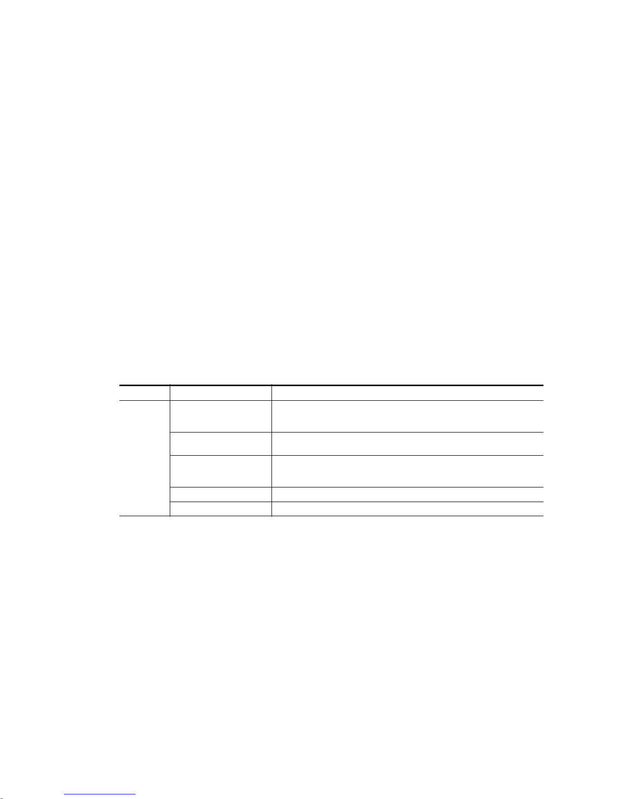
Category Standard Designed/tested for compliance with:
Safety
ANSI / UL60950 “Standard for Safety of Information Technology Equipment - Safety - Part 1: General
IEC 60950 “Standard for Safety for Information Technology Equipment - Safety - Part 1: General
CAN/CSA C22.2, No. 60950 “Standard for Safety of Information Technology Equipment - Safety - Part 1: General
EN60950 Safety of Information Technology Equipment, including Electrical Business Equipment.
2006/95/EC Low Voltage Directive
Requirements”, (ANSI/UL 60950-1, First Edition, Dated April 1, 2003, with revision
through and including November 26, 2003.)
Requirements”, (IEC 60950-1, First Edition, 2001, Corrigendum 1:10-2002)
Requirements”, (CAN/CSA-C22.2 No. 60950-1-03. First Edition Dated April 1, 2003,
with revisions through and including November 26, 2003)
28 JUPITER L-S and LCD Series Control Panel Instruction Manual
Page 29
Category Standard Designed/tested for compliance with:
EMC Directive 2004/108/EC
via EN 55103-1 and 2
EN 55103-1 Emission standards
EN55103-2 Immunity standards
EMI
US FCC Class A
Canada FCC Industry Canada
Australia & New Zealand: AS/NZS 3548
Audio, Video and Entertainment Lighting Control for the European Community.
Electromagnetic compatibility.
Product family standard for audio, video, audio-visual and entertainment lighting control
apparatus for professional use.
Part 1 Emissions, Environment E4
EN 55022: Class A Radiated and Conducted Emissions
EN 61000-3-2: Power Line Harmonic Emissions, Radiated Magnetic Field Emissions,
Peak Inrush Current
Electromagnetic compatibility--Product family standard for audio, video, audio-visual
and entertainment lighting control apparatus for professional use.
Part 2 Immunity, Environment E4
EN 50082-1: Immunity
EN 61000-4-2: Electrostatic Discharge “ESD” Immunity
EN 61000-4-3: Radiated RF Electromagnetic Field Immunity
EN 61000-4-4: Electrical Fast Transient/Burst “EFT” Immunity
EN 61000-4-5: Surge Immunity
EN 61000-4-6: Conducted RF Immunity
EN 61000-4-11: Voltage Dips, Short Interruptions and Voltage Variations
Annex A - Radiated Magnetic Field Immunity
Note: This only applies to assemblies sensitive to magnetic fields
CISPR Pub. 22 (1985)
Regulatory Notices
JUPITER L-S and LCD Series Control Panel Instruction Manual29
Page 30

Regulatory Notices
30 JUPITER L-S and LCD Series Control Panel Instruction Manual
Page 31

L-S series Introduction
Overview
The Jupiter L-S series Control panels are designed to control television
matrix routers through a Grass Valley Jupiter CM-4000 (or CM-4400)
Control System running the AccuSwitch application. Although the panels
are primarily intended to control Concerto, Trinix, Apex, and Venus
routers, any matrix router that can be controlled by an AccuSwitch can also
be controlled by these panels.
Note The CM-4000/4400 must be operating with Jupiter AccuSwitch version 7.6
or newer to support the L-S panels. The L-S panels are not intended for use
with CM-4000/Jupiter XPress applications nor with Jupiter VM-3000 System
Controllers.
Section 1
The L-S series is comprised of the following units:
• L32, L64, LD4, and LD16
S25, S50, S100, and SXY
•
L prefix panels have large (1/2- inch) multi-c
are equipped with smaller (3/8-inch) multi-color buttons.
L-S panels can be ordered with an AC or DC power supply. The AC power
supply mount
AC or DC line cord is disconnected to power down the panel.
s on the rear of the panel. No power switch is present. The
olor buttons. S prefix panels
JUPITER L-S and LCD Series Control Panel Instruction Manual31
Page 32

Section 1 — L-S series Introduction
PresetMenuLevel
Undo
Take
Protect/
Lock
Clear
L Series Control Panel Features
L32
Figure 1. L32 Control Panel
L64
Destination
Status
Preset
The L32 is a button-per-signal control panel equipped with a Destination/
Status color bitmap display. Features include:
• Assignable buttons on the front panel,
cking and protecting Destinations,
• Lo
• Scroll up/down Source and Destination selection
• Preset mode,
•Overrides,
• Level breakaway, and
• Sequence (Salvo) switching.
Figure 2. L64 Control Panel
The L64 is a button-per-signal control panel has the same features as the
L32, plus:
• Preset/Level display, and
•Undo.
32 JUPITER L-S and LCD Series Control Panel Instruction Manual
Page 33

LD4
Buttons #1 - 5
Buttons #6 - 10 Buttons #14 - 16
Buttons #11 - 13
Override
Source
L Series Control Panel Features
Figure 3. LD4 Control Panel
Note The buttons are numbered 1-5 on the top row and 6-0 on the bottom row.
The LD4 is a 16-category, full-matrix control panel. The panel provides
multi-level status and control of a single Destination (“XY Mode”), or, toplevel status and control of multiple Destinations
(“MD Control”). Features
include:
LD16
• Two color bitmap displays showing
up to four Destinations/page
• Destination/Status color bitmap display
• 16 category buttons for direct category selection
• Locking and protecting Destinations
• Scroll up/down Source/Destination selection
• Override
•Level breakaway
• Sticky-level control
• Source swap (flip-flop Take)
•(Salvo) switching
Figure 4. LD16 Control Panel
The LD16 is a 20-category, full-matrix, multi-level breakaway control panel.
The panel provides multi-level status and control of a single Destination, or,
JUPITER L-S and LCD Series Control Panel Instruction Manual33
Page 34

Section 1 — L-S series Introduction
top-level status and control of multiple Destinations (“MD Control”). Features include:
• Eight color bitmap displays showing up to 16 Destinations/page,
20 category buttons for direct category selection,
•
• Locking and protecting Destinations,
• Scroll up/down Source/Destination selection,
•Undo,
• Override,
• Level breakaway,
• Sticky-level control,
• Source swap (flip-flop Take), and
• Sequence (Salvo) switching.
34 JUPITER L-S and LCD Series Control Panel Instruction Manual
Page 35

S Series Control Panel Features
S50
Protect/
Lock
Panel
ID
S25/S50
Figure 5. S25 Control Panel
Figure 6. S50 Control Panel
The S25 (Figure 5) and S50 (Figure 6) panels provide button-per-Source
routing switcher control with 25 (or 50 r
eight-button Destination / level selection cluster. Other panel features
include:
S Series Control Panel Features
espectively) Source buttons and an
S100
•Level br
eakaway, and
• Configurable for various combinations of Destinations and levels:
• Control of one Destination and breakaway switching for eight
levels, or
• Control of two, three, or four Destinations and breakaway
switching for four levels, or
• Control of five, six, seven, or eight Destinations without breakaway
switching.
Figure 7. S100 Control Panel
The S100 is a 100 button-per-Source control panel. The panel includes two
color bitmap displays (Destination/Status and Preset/Level) and buttons
JUPITER L-S and LCD Series Control Panel Instruction Manual35
Page 36

Section 1 — L-S series Introduction
Level
Clear
Protect/
Lock
Buttons #6 - 10
Buttons #1 - 5
Buttons #14 - 16
Buttons #11 - 13
for scrolling through every available Source or Destination, plus a button
for level selection. Features include:
• Assignable buttons on the front panel,
• Lo
• Scroll up/down Source/Destination selection,
• Preset mode,
• Level breakaway,
• Sticky-level control, and
• Sequence (Salvo) switching.
SXY
Figure 8. SXY Control Panel
cking and protecting Destinations,
The SXY is a single Destination control panel that includes two color
bitmap displays (Destination/Status and Preset/Level). Category/number
keys and a rotating selector knob can be used to select a Sour
tion, a level selection, a Sequence, or an Overr
ide. The following features
ce, a Destina-
are included:
• Quick selection knob,
• 16 category buttons for direct category selection,
• Locking and protecting Destinations,
• Override,
• Level breakaway,
• Sticky-level control,
• Source swap (flip-flop Take),
• Sequence (Salvo) switching, and
•Scroll Take.
36 JUPITER L-S and LCD Series Control Panel Instruction Manual
Page 37

Specifications
Specifications
For mechanical, connection, power, and environmental specifications, refer
to Appendix A-L-S and LCD Panel Specifications.
JUPITER L-S and LCD Series Control Panel Instruction Manual37
Page 38

Section 1 — L-S series Introduction
Ordering Information
JUP-CP-L32 Series Control Panels
JUP-CP-L32-AC 32 button per Source control panel, with the ability to choose any Source or Destination
JUP-CP-L32-DC 32 button per Source control panel, with the ability to choose any Source or Destination
JUP-CP-L64 Series Control Panels
JUP-CP-L64-AC 64 button per Source control panel, configurable. Includes buttons for TAKE, LOCK/PRO-
JUP-CP-L64-DC 64 button per Source control panel, configurable. Includes buttons for TAKE, LOCK/PRO-
JUP-CP-LD4 Series Control Panels
JUP-CP-LD4-AC XY, Sixteen category, full featured routing switcher control panel. Includes three displays
JUP-CP-LD4-DC XY, Sixteen category, full featured routing switcher control panel. Includes three displays
JUP-CP-LD16 Series Control Panels
JUP-CP-LD16-AC XY or multiple Destination control panel. Twenty category, full featured routing switcher
JUP-CP-LD16-DC XY or multiple Destination control panel. Twenty category, full featured routing switcher
JUP-CP-S25 Series Control Panels
JUP-CP-S25-AC 25 x 1 Single Bus control panel. Pushbutton-per-Source routing switcher control panel
JUP-CP-S25-DC 25 x 1 Single Bus control panel. Pushbutton-per-Source routing switcher control panel
JUP-CP-S50 Series Control Panels
JUP-CP-S50-AC 50 x 1 Single Bus, Pushbutton-per-Source routing switcher control panel with 50 Source
JUP-CP-S50-DC 50 x 1 Single Bus, Pushbutton-per-Source routing switcher control panel with 50 Source
JUP-CP-S100 Series Control Panels
JUP-CP-S100-AC 100 button per Source control panel. 2U, two displays for Destination, status, presets and
JUP-CP-S100-DC 100 button per Source control panel. 2U, two displays for Destination, status, presets and
included in the input or output table. Includes one display. Rack or desk mounted 1 RU.
Includes AC power supply (JUP-ACPS-1RU).
included in the input or output table. Includes one display. Rack or desk mounted 1 RU.
Includes DC power supply. (JUP-DCPS).
TECT, LEVELS, AND PRESETS. Includes two displays. Rack or desk mounted 2RU.
Includes AC power supply. (JUP-ACPS-2RU).
TECT, LEVELS, AND PRESETS. Includes two displays. Rack or desk mounted 2RU.
Includes DC power supply. (JUP-DCPS).
and buttons for SOURCES, DESTINATIONS, sequences (salvos), and LEVELS. Categories
are user definable with re-legendable buttons. Includes AC power supply. (JUP-ACPS2RU).
and buttons for SOURCES, DESTINATIONS, SALVOS, and LEVELS. Categories are user
definable with re-legendable buttons. Includes DC power supply. (JUP-DCPS).
control panel. Includes 8 displays and buttons for SOURCES, DESTINATIONS, OVERRIDES, and LEVELS. Categories are user definable with re-legendable buttons. Rack or
desk mounted 2 RU. Includes AC power supply. (JUP-ACPS-2RU).
control panel. Includes 8 displays and buttons for Sources, Destinations, Over-rides, and
Levels. Categories are user definable with re-legendable buttons. Rack or desk mounted 2
RU. Includes DC power supply. (JUP-DCPS)
with twenty-five Source selection and eight level selection pushbuttons. Rack or desk
mounted 1RU. Includes AC power supply. (JUP-ACPS-1RU)
with twenty-five Source selection and eight level selection pushbuttons. Rack or desk
mounted 1RU. Includes DC power supply (JUP-DCPS).
selection and eight level selection pushbuttons. Rack or desk mounted 1RU. Includes AC
power supply (JUP-ACPS-1RU).
selection and eight level selection pushbuttons. Rack or desk mounted 1RU. Includes DC
power supply (JUP-DCPS).
levels. Joystick Override. Buttons for scrolling through every available Source or Destination, and level selections. Includes AC power supply (JUP-ACPS-2RU)
levels. Joystick Override. Buttons for scrolling through every available Source or Destination, and level selections. Includes DC power supply (JUP-DCPS)
38 JUPITER L-S and LCD Series Control Panel Instruction Manual
Page 39

Ordering Information
JUP-CP-SXY Series Control Panels
JUP-CP-SXY-AC XY, multiple level control panel. Category entry, quick-pick or Scroll Wheel for Source,
JUP-CP-SXY-DC XY, multiple level control panel. Category entry, quick-pick or Scroll Wheel for Source,
Destination or level selection, with two displays for obtaining the status of: DESTINATIONS, presets, levels and current status. Includes AC power supply (JUP-ACPS-1RU).
Destination or level selection, with two displays for obtaining the status of: DESTINATIONS, presets, levels and current status. Includes DC power supply (JUP-DCPS).
JUPITER L-S and LCD Series Control Panel Instruction Manual39
Page 40

Section 1 — L-S series Introduction
40 JUPITER L-S and LCD Series Control Panel Instruction Manual
Page 41

Hardware Installation
8536_43
44 mm
1.75 in.
88 mm
3.5 in.
432 mm
17 in.
483 mm
19 in.
2 RU Panel
1 RU Panel
This section describes hardware installation procedures for the L-S series
hardware panels.
Rack Mounting
Jupiter L-S panels mount into a standard 19 in. equipment rack. Panels are
1 or 2 rack units high (Figure9).
Figure 9. Panel Rack Mounting
Section 2
See L-S and LCD Panel Specifications on page 181 for dimensions for each type
of L-S panel.
Power Supplies
JUPITER L-S and LCD Series Control Panel Instruction Manual41
Two methods are available for powering the L-S series hardware panels:
• AC power supply (JUP-ACPS)
• DC power supply (JUP-DCPS)
Page 42

Section 2 — Hardware Installation
8536_37
The module used is specified at the time of order.
All power modules are auto-sensing (120-240 VAC, 50-60 Hz) and are supplied with a main power cable appropr
tion. No power switch is present. The AC cord is disconnected to power
dow
n the panel.
WARNING Do not connect any external power supply other than the approved “JUP-
The AC power supply is contained in a module that mounts on the rear of
the panel (Figure10).
Figure 10. Control Panel Dimensions with Options
iate for the user’s geographic loca-
DCPS” unit supplied by Thomson Grass Valley.
Network Wiring
8536_37
The L-S series panels are connected to the CM-4000 (or CM-4400) System
Controller via Ethernet or a Serial connection. Maximum length of a LAN
(Cat5 cable) connection is 329 feet (100 meters). The LAN must be capable
42 JUPITER L-S and LCD Series Control Panel Instruction Manual
Page 43

Button Labels
LAN 1 (Cat 5 Ethernet) cable.
Max. recommended length per
segment = 100 meters (329 ft)
CM-4000
System
Controller
(AccuSwitch)
100baseT Jupiter LAN
to Jupiter
File Server
64 LAN-operated
L-S panels per CM
maximum
8536_08
IP switch
VTR1VTR2VTR3VTR4VTR
5
VTR7VTR8VTR
9
VTR
6
of performing 100 Mb operations, and each Ethernet segment (hub to
panel) has a 100 meter limit. See Figure11.
Figure 11. LAN only system connections.
Button Labels
L32/L64/S100 Panels
Most L-S series panels are supplied with “typical use” button labels already
installed. Additional buttons can be labeled in the field. Two resources are
available for labels:
• A pre-printed/pre-cut transparency keycap label sheet is supplied with
each panel. See Keyca
p Transparency Labels on page 46.
• Microsoft Word files are available for creating custom labels. For more
information, contact Grass Valley Technical Support.
The L32 and L64 panels have 32 or 64 buttons respectively, on the left side
of the panel that can be used for Button-per-Source operation. The S100
panel has 100 buttons for this purpose. Using the label resources described
above, these buttons can be labeled 1 through 32, 64, or 100.
Figure 12. L32 with Custom Labels
Destination
Preset
JUPITER L-S and LCD Series Control Panel Instruction Manual43
Status
Page 44

Section 2 — Hardware Installation
VTR
1
CG
2
NET
3
VCR
4
1234
CAM
5
AUX EJ SS
5
678
REM
6
FILM
7
PTCH
8
STU
9
910
11 12
TEST
0
SAT FS MISC
13
14 15 16
8536_42
If the button assignments are more or less permanent, you may want to
label them more specifically. An example is shown in Figure12. See Source
Button Configuration on pa
LD4 Panels
The LD4 panels have a cluster of 16 buttons on the right side that can be
used for category/number operation. See Figure13.
Figure 13. LD4 Control Panel
These buttons have default categories assigned, as shown in Figure14.
Figure 14. Type CPESXTND Input Set Default Categories
ge 45 for more information.
LD16 Panels
It is possible to configure the panel with a custom category set. Note that
the button order of the set is grouped with the first 10 entries on the left and
the following 6 entries on the right. See Category Button Configuration on
page 46 for more information.
The LD16 includes a button cluster on the right side of the panel that can be
used for category/number selection. The default is shown in Figure15.
Figure 15. LD16 with Type ESL Category Set
Override
Source
44 JUPITER L-S and LCD Series Control Panel Instruction Manual
Page 45

S25/S50
1234
5
67
8
9
10
Button Labels
It is also possible to configure the panel with a custom category set. See Category Button Configuration on pa
ge 46 for more information.
The S25 and S50 panels have 25 or 50 buttons on the left side of the panel
that can be used for “Button-per-Source” operation. Using the label sheet,
these buttons can be labeled 1 through25 (or 50 respectively). If the button
assignments are more or less permanent, it might be desirable to label them
more specifically. See Source Button Configuration on pa
ge 45 for more infor-
mation.
Figure 16. S25
SXY Panels
These panels also include a cluster of eight buttons on the right side that
can be configured and labeled to select router levels. See CP Level Set on
page 61 for more information.
The SXY panels include a cluster of buttons on the left side that can be configured and labeled to select router levels. See CP Level Set on page 61 for
more information.
Figure 17. SXY Control Panel Showing Level Buttons
Level
Clear
The SXY panels also have a cluster of 16 buttons on the right side that can
be used for category/number operation. See Category Button Configuration
on page 46 for more information.
Protect/
Lock
Button Configuration Overview
Source Button Configuration
Source button functions are assigned on a panel by creating a Jupiter CP
Input set of type CPESXTND. The set table in this Input set consists of a list
JUPITER L-S and LCD Series Control Panel Instruction Manual45
Page 46

Section 2 — Hardware Installation
of button numbers and the name of the router input associated with each
button. The CP Input set is assigned to the panel using the MPK Devices
table.
For more information about button configuration, see CP Input and CP
Output Sets on page 61.
Category Button Configuration
Category buttons exist on some panels, allowing the pre-selection of categories of Sources or Destinations. The categor
ating a custom Jupiter CP Category set t
then be assigned to the CP Input set, which would in turn be assigned to
the panel using the MPK Devices table.
For more information about button configuration, see CP Input and CP
Output Sets on page 61.
Level Button Configuration
ies can be customized, by cre-
able. This CP Category set would
Some panels include a cluster of eight buttons on the right side that can be
configured and labeled to select router levels. This can be done by creating
a suitable CP Level set which lists the router levels in the order they should
be available using the eight buttons. The CP Level set is assigned to the
panel using the MPK Devices table.
For more information about level button configuration, see CP Level Set on
page 61.
Keycap Transparency Labels
A sheet of pre-cut transparency keycap labels, part no. 335835400, is available for use with Jupiter L-S Series Contr
0.38 x 0.38 inches (9.65 x 9.65 mm). The small labels measure 0.3 x 0.3 inches
(7.62 x 7.62 mm). The font is Helvetica condensed oblique See Figure 18 on
page 47.
ol panels. The large labels measure
46 JUPITER L-S and LCD Series Control Panel Instruction Manual
Page 47

Figure 18. Pre-Cut Transparency Keycap Labels
Shift
Source
Store
Take
Undo
Router and Control Systems
10099
8079
6059
4039
JEP Series Small and Large Button Keycap Legend Set
GV Part Number 335-8354-00A1
ID
2019
Red
Gold
Blue
Lock
Hold
Protect/
Protect/
Select
Ride
Still
Panel
Over
&
Assign
Keycap Legends for JEP "L" series Large Buttons
22
62
82
42
9897
77 78
9695
7675
5857
37 38
5655
3635
9493
73 74
91 92
71 72
5453
33 34
51 52
31 32
46
86
66
26
88
68
9089
7069
87
67
48
28
5049
29 30
47
27
846485
65
83
63
442445
25
43
23
81
61
41
21
Keycap Legends for JEP "S" series Small Buttons
Cam
Cam
Cam
Cam
Cam
Cam
Cam
Cam
Cam
Cam
Cam
222222 22222
Studio
Studio
Studio
Studio
Studio
Studio
Studio Frame
1817
Store
Seq
1615
T
Frame Select
Enter Sat
S
R
1413
VTR
9
J
1211
Test9VCR
9
VTR
8
I
VTR
7
H
Test8VCR
8
Test VCR
77
Emer Salvo
Protect
Edit
Q
P
Dest Preset
Clear Misc
OZ
NY
444
VTR
6
G
5
VTR
F
6
Test6VCR
5
Test5VCR
3
VTR
E
D
VTR
33
Test VCR
Test VCR
Patch
7
8
9
6
Patch
Patch
109
Server
99
87
Rem
9
88
Server
Server
77
Rem
8
Rem
7
Film
9
45
Net
9
32
CG
99
Film
7
8
Film Net
8
Net
7
CG
88
CG
77
3
4
5
6
Patch
Patch
Patch
Patch
444
66
Server
55
Server
6
Rem
5
Rem
33
Server
Server
3
Rem
Rem
4444
5
6
Film
Film
6
Net
5
Net
6CG6
5CG5
3
Film
Film
3
Net
Net
33
CG
CG
VTR
73
93
53
33
13
Studio
Studio
Studio
Chop Menu
Aux Lock
W
LV
Audio LevelKU
10099
000
1
VTR
CM
B
VTR
11
Test VCR
Test VCR
VTR
A
9896 97
Test VCR
94 95
4039
8079
6059
2019
Red
34 35 3836 37
7876 77
5856 57
74 75
54 55
1816 17
Store
Frame
Seq
14 15
J9T
0
Patch
Patch
Patch
000
11
Server
Server
1
Rem
Rem
Server
9291
Rem
908988
0000
1
Film
Film
11
Net
Net
11
CG
CG
85
Film Net
86 87
CG
83 84
3028 29 3231
7271
5251
7068 69
5048 49
Studio
1211
Test VCR
99
1098
Server
99
23 24 272625
65456766
46 47
63 64
43 44
Net
675
RemPatch
999
43
FilmCG
99
2
1
Aux
9
Aux
8
Aux
7
4
6
Aux
5
Aux
3
Aux
Aux
0
1
Aux
Aux
Aux
81 82
21 22
61 62
41 42
21
Aux
99
Cam
Cam
Cam
Cam
Cam
Cam
Cam
Cam
Cam
VTR
VTR
VTR
VTR
VTR
VTR
VTR
VTR
VTR
3 Hold
Protect
Salvo
Select
Preset
Gold
Blue
Undo
Protect/
Lock
Take
G Q Emer
Frame
SatEnter
7
8
IS
6
HR
Z Edit
DestX
F5P
4
EO
Lock
Level
Menu
Misc
Over
Still
Store
ID
Protect/
Source
Ride
Panel
Shift
Assign
Select
&
W Chop
Y Clear
V Aux
CM
2
DN
B1L
U AudioA0K
333333333
TestStudio VCR
Server
Studio
Studio
77
8
Test8VCR
66
Test VCR
77
88
Server
66
Server
Studio
Studio Test5VCR
5
Test VCR
44
55
Server
Server
44
FilmCG RemPatchNet
Net
Net
777
88
RemPatch
8
666
RemPatch
77
88
FilmCG
66
FilmCG
Net
Net RemPatch
555
RemPatch
444
FilmCG
55
FilmCG
44
TestStudio VCR
Server
Studio
Studio2Test2VCR
11
Test VCR
22
Server
11
Server
Studio Test0VCR
000
Server
FilmCG RemPatchNet
Net
Net
22
RemPatch
2
111
RemPatch
22
FilmCG
11
FilmCG
Net0RemPatch
00
FilmCG
00
33
Aux
77
88
Aux
66
Aux
Aux
55
Aux
44
Aux
22
Aux
11
Aux
Aux
00
Tally/
Level
ID
Panel
Enable
All
Level
Config
Tally/
Level
ID
Panel
Enable
All
Level
Config
Button Labels
JUPITER L-S and LCD Series Control Panel Instruction Manual47
Page 48

Section 2 — Hardware Installation
48 JUPITER L-S and LCD Series Control Panel Instruction Manual
Page 49

Section 3
Software Installation & IP
Addresses
Introduction
The L-S series panels operate with the Jupiter AccuSwitch control system
using Ethernet LAN or Serial connections. This functionality requires compatible software versions and IP address
system devices on the network.
es must be used by all Jupiter
L-S series hardware panels are shipped with the
There is no need to install panel software on newly shipping systems. However, the IP address must be set on each
work. The NetConfig application is used to discover and set IP addresses
he L-S series panels. NetConfig is also used to update L-S series panel
of t
software, by transferring panel code from the computer running NetConfig
directly to the panels. The L-S panels communicate with the CM-4000/CM4400 controller boards via the ESLAN or Serial protocol. Once communications is established, the L-S panels wil
tions from the Jupiter CM-40
The panel software update mechanism above is different from that used by
the Jupiter cont
boards update their software via Bootstrap Protocol (bootp) and Trivial File
Transport Protocol (TFTP) when activating a configuration. The controller
boards send out a “bootp” request and the file server responds by indicating what files need to be downloaded from where. The controller boards
then us
consist of the.sys files (accuswch.sys, jupiter.sys) and a.cfg file. The .sys file
is the operating system and the .cfg file is for configuration. The .sys file is
installed during the Jupiter install process and the .cfg file is created after
compiling the configuration and activating it.
e TFTP to download the files from the Jupiter file server. The files
rol system itself. Jupiter (VM, SI, and CM-4000) controller
00/CM-4400 controller.
panel so it can operate on the net-
l receive their operational configura-
current software installed.
Note The Jupiter Control Center and NetConfig use the same TFTP port. NetConfig
JUPITER L-S and LCD Series Control Panel Instruction Manual49
cannot be used to send software to the Control panels if the Jupiter Control
Center is running. Configuration changes from the Jupiter Control Center
could also be interrupted if NetConfig is running at the same time, depending
which application has the port bound.
Page 50

Section 3 — Software Installation & IP Addresses
Software Installation
NetConfig Installation
The Grass Valley NetConfig application is supplied on the L-S Panels Software CD that is shipped with the panel.
1. Insert the Jupiter L-S Panels Software CD into the Jupiter file server
computer. The NetConfig Setup application should automatically run
and display a Welcome screen (Figure 19).
Figure 19. NetConfig Installation Welcome Screen
50 JUPITER L-S and LCD Series Control Panel Instruction Manual
Page 51

Software Installation
2. Click Next and follow the instructions shown on the screens, accepting
the defaults (Figure 20).
Figure 20. NetConfig Installation Screens
3. After NetConfig has successfully installed, click Finish.
JUPITER L-S and LCD Series Control Panel Instruction Manual51
Page 52

Section 3 — Software Installation & IP Addresses
L-S Panels Installation (on Jupiter File Server)
1. After NetConfig has been installed, the L-S Panels installation
application will launch. This program loads files from the CD onto the
computer running the installer program. You can later use NetConfig
to install the software directly on the L-S series panels (Figure 21).
Figure 21. L-S Panels Installation Welcome Screen
2. Click Next and follow the instructions shown on the subsequent screens,
accepting the defaults (Figure 22).
Figure 22. L-S Panels Installation Screens
52 JUPITER L-S and LCD Series Control Panel Instruction Manual
Page 53

3. Click Finish when the L-S Panels software installation completes.
CM-4000 System Controller
10/100baseT
Jupiter LAN
IP switch
Panel IP
192.168.253.102
Panel ID
02
Panel IP
192.168.253.101
Panel ID
01
Panel IP
192.168.253.164
Panel ID
64
Jupiter
File Server IP
192.168.253.1
IP
192.168.253.10
8536_13
NOTE: 64 Panels per CM maximum
Network IP Addresses
This section describes IP (LAN) addressing procedures for the L-S series
hardware panels.
IP connection and configuration allows Ethernet operation and provides a
downloading path for softwar
controller (CM-4000 or CM-4400), and Jupiter file server PC must be on the
same IP network, or be connected through a network router/gateway.
Single Network IP Configuration
Figure 23 shows an example with the Jupiter equipment (file server, Jupiter
System controller (CM-4000 or CM-4400), and L-S panel) is in an isolated
network envir
Network IP Addresses
e upgrades. The L-S panel, Jupiter System
onment.
Figure 23. LAN System Addressing Example.
JUPITER L-S and LCD Series Control Panel Instruction Manual53
Page 54

Section 3 — Software Installation & IP Addresses
Multi-Network IP Configuration
A “remote” L-S panel can be placed on a network separate from the other
Jupiter devices. For example, L-S panel can be placed on a facility LAN. In
Figure 24, an IP router serves as a gate
Figure 24. LAN Addressing With Remote L-S Panel Example
way between two networks.
Jupiter
File Server IP
192.168.253.1
CM-4000 System Controller
IP switch
Gateway
IP
192.168.1.1
10/100baseT
Jupiter LAN
Facility LAN
Panel ID
03
Panel ID
02
Panel ID
01
IP
192.168.253.10
Panel IP
192.168.253.103
Panel IP
192.168.253.102
Panel IP
192.168.253.101
NOTE: 64 Panels per CM maximum
Remote L-S panel
Configuration is similar to that just described, except that the address of the
gateway must be entered on the web page for the remote panel.
For more information on IP addressing, see either the Jupiter CM-4000
Installation and Operating
ating manual.
54 JUPITER L-S and LCD Series Control Panel Instruction Manual
Panel ID
64
Remote Panel IP:
192.168.1.164”
Gateway:
192.168.1.1
8536_17r1
manual or the Jupiter CM-4400 Installation and Oper-
Page 55

Network Configuration Procedure (NetConfig)
The network configuration procedure requires the Grass Valley NetConfig
application v2.0.9 or newer. NetConfig is supplied on the CD shipped with
the panel (see NetConfig Installation on page 50).
The network configuration procedure consists of two parts:
Network IP Addresses
• Setting the panel IP address, subnet
• Setting the panel “Device Number” and other Jupiter values.
Setting IP Addresses on L-S Panels
When L-S panels are being installed for the first time, the user will need to
load the NetConfig application on the Jupiter file server PC.
Note The following is a summary of the NetConfig portion of the configuration pro-
cess. For a complete description of the NetConfig application, refer to the
NetConfig Instruction manual.
1. Connect the panel to the IP switch on the Jupiter network. Apply
power. If the panel has a display window, you should see the default IP
address of the panel.
If there are other devices on the Jupit
they should be disconnected at this time.
2. Launch the NetConfig application from the control-system file server.
3. Expand the “IP View.”
value, and gateway address, and
er LAN with this same address,
You should see the Jupiter file server name and IP addr
4. Expand the listing under the Jupiter file server.
You should see the panel name and the factory default address of the
panel(s).
meaning that the panel address needs to be changed as described
below.
If you do not see the panel name(s) that you expect:
• Select “Configure > Netconfig Options > Clear Views and Re-dis-
• Check to see that the “IP View > Product Web Access Pages” are not
In some cases, you may need to cycle power to the panel.
5. Change the panel IP address to place the panel on the Jupiter network:
a. Select the panel requiring an address change.
JUPITER L-S and LCD Series Control Panel Instruction Manual55
In most cases, you will see a red dot next to the panel name,
.”
cover
being covered by other views, such as “Device view” or “Facility
View.”
ess.
Page 56

Section 3 — Software Installation & IP Addresses
b. Select the “Set IP” button along the top of the NetConfig window.
You should see the “Change IP Addresses” menu.
c. In the “Select Device Type” field, select “All Devices.”
d. Select the panel requiring an address change.
e. Select “Edit.”
f. IP address: set to a unique value within the same network as the
Jupiter file server.
For example, if the Jupiter file server
the panel address should be changed to reside in the 192.168.253.x
network (such as “192.168.253.101”).
g. Subnet Mask: set to 255.255.255.0 (Class C network).
h. Gateway: not used in a simple network environment.
If the panel and the server are on separate networks, the gateway
connecting
i. Select “OK,” “Apply Changes,” and “Close.”
In the IP View, a green dot should indicate that the panel is fully
connected
The panel itself should reboot.
j. Proceed to Setting Jupiter Values for L-S Panels below.
them must be specified. See page 54.
.
Setting Jupiter Values for L-S Panels
During the following steps, you will need to know the IP address of the
AccuSwitch system that will be associated with the panel. Use the Jupiter
File Server JNS Control Center application to determine the CM-4000/CM4400 IP address (the Control Center application is described in both the
Jupiter CM-4000 Installation and Operating manual and the Jupiter CM-4400
Installation and Operating manual).
address is 192.168.253.1, then
1. Using NetConfig, click on the name of the panel (as described in Step 4
above).
You should see the Product Web Access page for the panel.
2. Select “Panel Network.”
You should see the Panel Network Configuration page.
a. The “Net-1 IP Settings” should already be correct (they were set
b. Uncheck “Net-1: Set DHCP Mode” and “Net-2: Set DHCP Mode”
56 JUPITER L-S and LCD Series Control Panel Instruction Manual
using the “Change IP Addresses” menu described above).
(unless IP addresses are being set automatically by a Dynamic Host
Configuration Protocol server).
Page 57

Finding the Physical Location of a Panel
c. ES-LAN/Serial Device #:
Each panel connected to an AccuSwitch controller must be given a
unique number.
• Enter a number from 1 to 64 for a LAN only system.
Enter a number from 1 to 16 for a Serial only system.
•
The “Device #” is referred to as the “Device
and the “Address” on the Jupiter MPK Devices table. See
Section 4-Jupiter System Configuration.
d. ES-LAN Primary Host IP: enter the IP address of the Control
module associated with this panel.
e. ES-LAN Secondary Host IP: enter the IP address of the redundant
Control module (if any).
3. Select “Save New Settings.”
This will apply the settings and reboot the panel. Y
type of status response from the router
4. Go to the next panel and repeat the steps above.
Note For initial installations, the Jupiter/AccuSwitch control system must be con-
figured in order for the Control module to communicate with the panel.
Proceed to Section 4-Jupiter System Configuration.
Finding the Physical Location of a Panel
ID” on the panel itself
ou should see some
NetConfig can be used to send an “identify device” signal to a particular
panel, causing the panel to display a flashing red and yellow checkerboard
pattern.
1. Use Device View and go to Router > Jupiter > Panels.
2. Expand the panel type name and right click on the name of the panel of
interest.
3. Select “Identify Device” from the pop-up menu.
The panel will flash the checke
in the Options menu.
JUPITER L-S and LCD Series Control Panel Instruction Manual57
rboard pattern for the number of seconds set
Page 58

Section 3 — Software Installation & IP Addresses
L-S Panel Software Update
Note NetConfig and the Jupiter Control Center use the same TFTP port. Only one
will own the port at a time. When updating control panel software the Jupiter
Control Center should be shut down, and NetConfig must be closed to send
any Jupiter configuration changes.
NetConfig is used to update the operating software that resides on each L-S
series panel. NetConfig accomplishes this by sending the flash files
installed onto the computer running NetConfig (Jupiter file server recommended) to the panels via the network. For this reason, panel IP addresses
ust be set correctly before L-S panel software can be updated. See Setting
m
IP Addresses on L-S Panels on pa
1. Launch NetConfig.
2. Click on the Load Software tab at the top of the NetConfig screen. The
software load window will open (Figure 25).
Figure 25. L-S Panels Installation Welcome Screen
ge 55 for more information.
3. Navigate to the Jupiter/Panels folder in the left pane and select the type
of panel whose software you wish to update.
4. Select the specific panel(s) in the right pane you wish to update.
5. Ensure the Re-Boot when complete box on the lower left is checked.
6. Click Load. The software will be loaded to the selected panels and the
panels will reboot.
58 JUPITER L-S and LCD Series Control Panel Instruction Manual
Page 59

Section 4
JEP1 CPESXTND 01
JEP2 CPESXTND 02
1
MPK Devices
MPK
Expansion
Pass
Board
CM1
Port Address Input Sets Output Sets Level Set Overide Set Sequence Set
2
CM1 KXYZINP KXYZOUT KXYZLEV
Devices word
In Panel Out Panel
JEP64 CPESXTND 64
64
CM1 KXYZINP KXYZOUT KXYZLEV
KXYZINP
KXYZOUT
K
KXYZLEV
Type
Device
75
92
Jupiter System Configuration
The following overview of L-S series panel configuration assumes that the
reader is familiar with the Jupiter Facility Control System. Please refer to
the Jupiter CM-4000 Installation and Operating manual or the Jupiter CM-4400
Installation and Operating manual for specific information.
MPK Table Entries
The Jupiter MPK table is used for configuration purposes. The example
shown in Figure 26 applies to the system shown in Figure 23 on page 53.
Figure 26. MPK Devices Table
JUPITER L-S and LCD Series Control Panel Instruction Manual 59
MPK Devices:This column is used to create a name, up to eight characters in
length, for each L-S panel. This name must be unique system-wide.
Device Type: Select type “CPESXTND” from the pull-down menu.
Expansion: For L-S series panels, leave unchecked.
Password: A password level will only need to be entered if you wish to
disable the Configuration and Setup menus on the Control panel. See the
Disabling the Configuration and Setup Menus on the Control Panel section
below for more information.
Note Panels can be configured to force unlock and force un-protect any destination
regardless of what panel locked or protected it, depending on what is entered
in the Password column. See the 7.8.1 Jupiter Release notes (part #
071827511) for more information.
: Name of CM-4000 or CM-4400 that is associated with this panel. The
Board
Source of this name is the Network Description table.
Page 60

Section 4 — Jupiter System Configuration
Port: This field is not used during a LAN-only installation.
Address: Panel address from 01 to 64 (01 to 16 for Serial). This address must
be unique for panels that are associated with the same Control module. L-S
panels are normally shipped with a panel address of “01.” This number is
referred to as the “Device Number” on the IP configuration page and “ID”
within the L-S menu system.
Input Set: The name of the CP Input set that will be assigned to this panel.
The usual practice is to have one CP Input Set, containing the names of all
Sources, applied to all panels. However, special CP Input Sets could be
created which list only selected Sources; such a set could be used to prevent
certain panels from selecting specific Sources.
• For a Button-per-Source panel (L32, L64, S25, S50, and S100) the CP
nput set can be used to assign Sources to specific Source buttons where
I
the first Source in the table corresponds to the first button on the panel,
etc.
In Panel: This column is not used for L-S panels.
Output Set: Output Set name. Creation of CP Output Sets is described in both
the Jupiter CM-4000 Installation and Operating manual and the Jupiter CM4400 Installation and Operating manual.
• For an S25 or S50 panel, with entry of a single Destination name, the
nel will operate as a one-Destination panel. The eight-button cluster
pa
on the right-hand side of the panel will be used to control the first eight
levels of the router.
• For an S25 or S50 panel, with selection of an Output Set with two, three,
or four Destinations defined, the panel will operate as a two-, three-, or
four-Destination panel respectively. With respect to the eight-button
cluster on the right-hand side of the panel, the top row of four buttons
will be used to select the Destination; the bottom row of four buttons
will be used to control the first four levels of the router.
• For an S25 or S50 panel, with selection of an Output Set with five, six,
seven, or eight Destinations defined, the panel will operate as a five-,
six-, seven-, or eight-Destination panel respectively. The eight-button
cluster on the right-hand side of the panel will be used to select the Destination.
• For all other L-S series panels, if an actual CP Output Set is selected,
then the control panel will be able to control all the Destinations listed
in that Set; depending on the contents of the set, this would allow for
full-matrix or multi-bus control. Alternatively, this field can be used to
enter the name of a single switcher Destination to be controlled; the
Source of the Destination name is the Switcher Output table.
Out Panel: This column is not used for L-S panels.
Level Set: Select the CP Level Set name.
60 JUPITER L-S and LCD Series Control Panel Instruction Manual
Page 61

Override Set- (Does not apply to S25 and S50. Optional for all other L-S
panels.) Select a CP Override set name. A CP Override set can be used to
define a set of Sources and level combinations that can be quickly applied
to a panel controlled Destination. Up to 10 pages of overrides (80 overrides
total) may be defined. The order in which the overrides are listed on the CP
Override set table will be the order in which they appear on the panel.
Sequence Set- Select a CP Sequence set name. A Sequence set is used to
execute a list of switches with a single command. (Does not apply to S25
and S50and is optional for all other L-S panels.)
Control Panel Sets
Switcher Sources and Destinations for the L-S panels are specified by creating a Jupiter CP Level Set, a CP Input Set, and a CP Output Set. These sets
e assigned to each panel using the MPK Devices table (Figure 26).
ar
Control Panel Sets
CP Level Set
The CP Level Set used for L-S panels is specified as type CP3800.
With L-S panels, the CP Level Set establ
displayed on the panel and the display mnemonics used for the various
levels (“Video,” “Left,” etc.). The display mnemonics have a maximum
length of eight characters.
CP Input and CP Output Sets
The CP Input and Output Set is specified as type CPESXTND for all L-S and
LCD models. The number of category buttons varies from panel to panel,
as indicated in Tab le 1.
Table 1. Panel Category Buttons
L-S Panel Model
L32 None
L64 None
LD4 16
LD16 20
S25 None
S50 None
S100 None
SXY 16
LCD 98 (20 categories at a time)
Number of Category
Buttons (default)
ishes the order in which levels are
JUPITER L-S and LCD Series Control Panel Instruction Manual 61
Page 62

Section 4 — Jupiter System Configuration
SETUP1
8536_22
CAM1
SETUP1 CAM2
1
2
SETUP1 CAM3
SETUP2 CAM1
3
4
SETUP2 CAM2
SETUP2 CAM3
5
6
Sequence
Input
Logical
Sequence Set - SETUP
MON1
MON2
MON3
VTR1
VTR2
VTR3
Output
Logical
YYYY
Levels
YYYY
YYYY
YYYY
YYYY
YYYY
For example, the LD4 panel provides a maximum of 16 categories; therefore
categories 17 through 98 (as shown by the Jupiter editor) will not be supported. The CP Input and Output sets ar
acter mnemonics displayed on the panel.
Further, the CP Input set determines which of the S25, S50, S100, L32, and
utton-per-Source buttons is assigned to which Source. The upper left-
L64 B
hand button of the panel will select the first Source listed on the CP Input
Set created and selected for this particular panel, the next button to the
right will select the next listed Source, etc.
Note The total number of units (Jupiter Entry Numbers) within a category is limited
to 4096. For example, the total number of machines within category “VTR” is
limited to 4096.
Sequence Set
A control panel’s sequence (salvo) button or menu setting can be used to
execute pre-built Jupiter sequences, where a sequence is a list of switches,
which switches one or more Sources to one or more Destinations.
e also the Source of the eight-char-
Setting Up a Salvo with a Sequence Set
A Jupiter sequence is built using the Jupiter Sequence Set table, an example
of which is shown in Figure 27.
Figure 27. Sequence Set Table
The sequence set is given an eight-character (max) name and is of type
“CP3800.”
In this example, sequence set “SETUP
and “SETUP2.” “SETUP1” will switch Cameras 1 through 3 to Monitors 1
through 3 with a single Take command. If the Sources and Destination are
valid for all the levels marked yes, then the actual number of switches will
62 JUPITER L-S and LCD Series Control Panel Instruction Manual
be 3 times the number of levels (3 events x 4 levels = 12 switches).
“SETUP2” will switch the cameras to VTRs 1 through 3. Each sequence can
use 100 event sequences as of Jupiter 7.8.1 (table rows).
” contain two sequences: “SETUP1”
Page 63

Control Panel Sets
The sequence set must be assigned to the panel on the Jupiter MPK Devices
table.
For additional information regarding Jupiter se
them to control panels, refer to either the Jupiter CM-4000 Installation and
Operating manual or Jupiter CM-4400 Installation and Operating manual.
Note Sequences are executed in slightly different ways, depending on the buttons
available on each panel type. Refer to the specific instructions for each panel.
quences and assigning
Disabling the Configuration and Setup Menus on the Control Panel
You can disable the Configuration and Setup menus on the Control panel.
Some of the locked-out settings will still be accessible from the Control
Panels Web page; such as the ability to change the Device ID or the Connection Type settings. Also the Setup menu wil
Password Level setting, if the panel is not connected to the Control module
by either a LAN or a Serial connection. You will need to set the Password
level in the MPK Devices table to disable the Configuration and Setup
menus.
Follow these steps to disable the Con
Control panel:
1. Open the MPK Devices table.
2. Enter the preferred setting in the Password Level column (see
Figure 26):
l be accessible, regardless of the
figuration and Setup menus on the
• Enter a number from 1 to 89 to disable both the Configuration and
Setup menus.
• Enter a number from 90 to 94 to disable only the Setup menu.
• Enter a number 95 and higher to enable both menus.
Note If the Password Level column is left blank, both menus will be accessible.
3. Apply the changes by compiling the appropriate sets.
Disabling Specific Buttons on the Control Panel
You can disable the buttons for a Destination on the Control panel. You will
need to set the mnemonic for a source or destination to be “BLANK” (see
Figure 28).The panel will then disable the button for t
tion.
hat source or destina-
JUPITER L-S and LCD Series Control Panel Instruction Manual 63
Page 64

Section 4 — Jupiter System Configuration
Follow these steps to disable the buttons for a Source or Destination on the
Control panel:
1. Open the CP Output table.
2. Enter the text, “BLANK” in the mnemonic column (see Figure 28).
Figure 28. Output Set Table
3. Enter the number of the desired button in the Button Assignment
column. For example,:
• Buttons 1-32 for the L32 panel.
• Buttons 1-64 for the L64 panel.
Compiling
• Buttons 1-100 for the S100 panel.
Apply the changes by recompiling the set.
be disabled.
Note An output called BLANK can be added to the Switcher Output table, without
assigning a physical output. This addition allows the BLANK output to be
selected in the control panel set.
Before the panel(s) can be operated, the edited Jupiter set must be compiled
and the appropriate configuration set made active using the Control
Center. For more information, refer to either the Jupiter CM-4000 Installation
and Operation manual or the Jupiter CM-4400 Installation and Operation
manual.
Following this step, the AccuSwitch contr
cating with the panel(s); i.e., the panel
status.
The associated button will then
ol system should start communi-
(s) will indicate some form of router
64 JUPITER L-S and LCD Series Control Panel Instruction Manual
Page 65

Connecting the L-S, LCD
Panel
The L-S and LCD Panels can be connected to the AccuSwitch System Controller via a 115k Baud serial bus (Cannot be greater than 2000 feet); or via
Cat 5 Ethernet connection (Cannot be greater than 329 feet per segment).
a
Note An Ethernet connection is required for software upgrade purposes.
Section 5
JUPITER L-S and LCD Series Control Panel Instruction Manual 65
Page 66

Section 5 — Connecting the L-S, LCD Panel
Serial data cable (see p age 22)
LAN (Cat 5 Ethernet) cable.
Max. recommended length per
seqment = 100 meters (329 ft)
Temporary LAN connection for
so ftware up grad e
AccuSwitch CM-4000 System Controller
Serial
Por ts
100baseT Jupiter LAN
IP switch
to Jupiter
File Server
Serial bus
Serial bus
853602
Figure 29. L-S and LCD Panel Serial Connection
66 JUPITER L-S and LCD Series Control Panel Instruction Manual
Page 67

Hardware Installation
The L-S and LCD Panels can be connected to the AccuSwitch System Controller via a 115k Baud serial bus or via a Cat 5 Ethernet connection. It is also
ible to combine these methods by connecting some panels through a
poss
Serial port and others through the LAN. Each of these options is described
below.
Serial System
The Serial arrangement assumes that the L-S or LCD Panels will be operated in Serial mode, with the LAN only connected to one panel at a time
and only
to have a different IP address for each panel.
Hardware Installation
during software upgrades. In this arrangement, it isn't necessary
An example of a system where the L-S or LCD
Serial mode (the temporary LAN connections are for software upgrade) is
shown below in Figure 30.
Panels will be operated in
JUPITER L-S and LCD Series Control Panel Instruction Manual 67
Page 68

Section 5 — Connecting the L-S, LCD Panel
AccuSwitch CM-4000/4400 System Controller
Serial
Por ts
100baseT Jupiter LAN
16 L-S panels per
serial bus maximum
IP switch
Serial
buses
Panel IP
“192.168.253.102”
Panel ID
“02”
Panel IP
“192.168.253.101”
Panel ID
“01”
Panel IP
“192.168.253.116”
Panel ID
“16”
Panel IP
“192.168.253.117”
Panel ID
“01”
IP “192.168.253.10”
Jupiter
File Server
“192.168.253.1”
8536_14
Serial data cable (see p age 22)
LAN (Cat 5 Ethernet) cable.
Max. recommended length per
seqment = 100 meters (329 ft)
Temporary LAN connection for
so ftware up grad e
Figure 30. Serial system addressing (example).
68 JUPITER L-S and LCD Series Control Panel Instruction Manual
Page 69

Serial Data Cables
1
2
3
7
8
1
2
8
P1
DB9P
(male)
Shield (drain)
Green
Black
White
P2
DB9P
(male)
3
7
Red
Ground
CM-4000 System
Controller
(bus controller)
Control panel or
VTR
(tributary)
Receive A (-)
Tr ansmit A (-)
Receive B (+)
Transmit B (+)
Transmit B (+)
Tr ansmit A (-)
Receive B (+)
Receive A (-)
Frame ground
Individually shielded, twisted pairs
Ferrite core
Ferrite core
Green
Black
White
Red
8536_11
The RS-422 cables that are used to connect the AccuSwitch System Controllers to the L-S and LCD Control panels
ground) cable. The maximum length per bus, at 115k Baud, is 610 meters
(2000 feet).
The rear panel Serial Data Cable connectors on the CM-4400 or CM-4000
nd Control panels are 9-pin D, female. The control panel connectors are
a
arranged for loop-through wiring and no termination is required. These
connectors are ESbus compatible, however, it should be noted that the
Thomson serial data cables use only 5 of the 9 pins that are described in the
ESbus specification.
Serial Data Cables
consist of a 4-conductor (plus
The following cables are available, with 9-pi
n D male connectors installed,
already made from Grass Valley (VDE cables include ferrite cores):
Table 2.
1 meter (3.3 ft.) 8 meters (26.2 ft.)
2 meters (6.6 ft.) 16 meters (52.5 ft.)
4 meters (13.1 ft.) 32 meters (105 ft.)
For those who wish to prepare their own cables,
Figure 31. The cable itself should be Belden
the pin-outs are shown in
8723 or equivalent.
Details concerning ferrite cores are given in Figure 32.
Figure 31. Serial data cable wiring. Reference: “Assembly, BCS-3000 Serial Data Cable,” Grass
Valley drawing no. 01-041600-TAB.
JUPITER L-S and LCD Series Control Panel Instruction Manual 69
Page 70

Section 5 — Connecting the L-S, LCD Panel
VDE EMI/RFI Modifications to Serial Data Cables
User-supplied serial data cables for VDE installations require a ferrite core
placed over each end of the cable, and adjacent to the connector (see
Figure 32 below).
Figure 32. Serial data cable VDE modifications.
Type 43 material
0.250 inch (6.35 mm) inside diameter
0.95 inch (24.13 mm) length (or longer)
Type 43 material sources
Fair Rite, part no. 2643480002
Fair Rite Products Corp., P .O. Box J, Commercial
Row, Wallkill, NY 12589, USA; Tel. (914) 895 2055.
Chomerics, part no. 83 10 A636 1000
Chomerics Inc., 77 Dragon Ct., Woburn, MA 01888
USA; Tel. (617) 935 4850.
8536_12
70 JUPITER L-S and LCD Series Control Panel Instruction Manual
Page 71

IP Configuration Procedure
1. A Control panel only needs an IP address if it is using the LAN for
NetConfig (Software updates). Determine the present IP address of the
1st panel. This step will be different for each panel, see the previous
chapters in this manual for your specific panel’s information.
2. Disconnect any devices on the Jupiter LAN with the same IP address.
Serial Data Cables
L-S or LCD panels are normally shipped with a
At the file server PC
You must have Administrator privileges to change Internet settings on a
Windows PC.
1. Use the PC's Network Settings dialog to set the TCP/IP address within
the same local network as the L-S or LCD Panels.
Note This connection will only be temporary if you are using a Serial connection.
For example, if the L-S or LCD Panels address is presently
192.168.253.100, then the PC address should be changed to be compat-
ible with the 192.168.253.x network (such as “192.168.253.1”). The PC's
sub ne
simple network environment, all other TCP/IP network settings are
irrelevant at this point.
2. Reboot the PC to apply the changes.
Note You can use the MS-DOS command, ipconfig to verify the settings after
t mask should be set to 255.255.255.0 (class C network). In a
the PC has been restarted.
default IP address.
3. Start the Internet browser of choice (For example, MS Internet
Explorer).
The browser’s Proxy setting must be t
setting for Internet Explorer, go to Tools > Internet Options > Connections > LAN Settings.
4. Enter the L-S or LCD Panels IP address in the URL window or Start
NetConfig. This will display the L-S or LCD Panel Description web
page.
5. Click the Panel Network hyperlink. The Panel Network Configuration
page will then appear.
JUPITER L-S and LCD Series Control Panel Instruction Manual 71
urned off. To check the Proxy
Page 72

Section 5 — Connecting the L-S, LCD Panel
Figure 33. The L-S or LCD Panels Web Page
The Panel Information fields are system generated.
Panel Network Configuration
Follow these steps to configure the Panel Network.
72 JUPITER L-S and LCD Series Control Panel Instruction Manual
Page 73

Serial Data Cables
Net-1 IP Settings
Figure 34. Net-1 IP Settings
1. Enter a unique value in the Ethernet IP field. This IP address must be
within the same network as the AccuSwitch controller.
For example, if a CM-4000 address is 192.168.253.10, then the L-S or
LCD Panels address should be changed to reside in the 192.168.253.x
network (such as “192.168.253.101”).
2. Enter 255.255.255.0 in the Subnet Mask field.
3. Enter a unique value in the Gateway field. This number is similar to the
Ethernet IP, except the last set of numbers should be “1.”
If the L-S or LCD Panels and the AccuSwitch contr
networks, the gateway connecting them must be specified.
Net-2 IP Settings:
Not used to configure the panel.
Network Mode Selection - Enable DHCP if Box Checked
You must have a DHCP server to use this option.
Figure 35. Enable DHCP Settings
Follow these steps if you wish to use DHCP:
1. Select or place a check in, the Net-1: Set DHCP Mode check box to turn on
DHCP mode.
oller are on separate
2. Select or place a check in, the Net-2: Set DHCP Mode check box to turn on
3. Enter the amount of time, in seconds, for the panel to try to connect to
JUPITER L-S and LCD Series Control Panel Instruction Manual 73
DHCP mode.
the DHCP server before the connection will time out in the DHCP Mode
time-out (sec) field.
Page 74

Section 5 — Connecting the L-S, LCD Panel
Connection Type
There are different types of connections. Follow these steps to set the connection settings for the different types:
LAN Systems
Figure 36. Example of the LAN Connection Type
1. Select the LAN radio button for a LAN only system.
2. Enter the Device Number in the LAN/Serial Device # field.
3. Enter the IP address of the Host in the LAN Primary Host IP field.
4. Enter the Redundant IP address of the Host in the LAN Secondary Host
IP field.
5. Select the amount of time to wait for a response from the Control
module before timing out from the LAN Response Time-out dropdown list.
This setting is helpful if you have
away from a Control module. The options are: 20mS, 40mS, 60mS,
80mS, 100mS, 250mS, 500mS, and 1S.
Control panels located a long distance
Serial system
1. Select the Serial radio button for a Serial system.
2. Enter the Device Number in the LAN/Serial Device # field. The number
entered cannot be greater than sixteen.
Note If the number entered exceeds the limits, 1-16, the field will appear red
(Figure 37) and you will need to enter a different number.
Figure 37. The LAN/Serial Device # Field- With an In-correct Number
The Primary and Secondary LAN fields will not be editable.
74 JUPITER L-S and LCD Series Control Panel Instruction Manual
Page 75

Forcing the Panel to Reset - if Box is Checked
1. Select the Do Reset check box. This will force the panel to reset and use
the new settings.
2. Click the Save New Settings button. Clicking the Cancel Changes button will
close the page without saving any changes. Clicking the
button will restore the settings that the panel was shipped with.
Serial Data Cables
Factory Defaults
JUPITER L-S and LCD Series Control Panel Instruction Manual 75
Page 76

Section 5 — Connecting the L-S, LCD Panel
CP1 CPES-SER 011
1
1
CP2 CPES-SER 02
1
MPK Devices
MPK
Expansion
Pass
Board
CM1
Port Address Input Sets Output Sets Level Set Overide Set Sequence Set
2
CM1 CP_IN CPOUT CP_LEV
Devices word
In Panel Out Panel
CP16 CPES-SER 16
16
CM1 CP_IN CPOUT CP_LEV
CP17 CPESXTND 01
17
CM1 CP_IN CPOUT
CP_LEV
CP_IN
CPOUT
CP_LEV
Ty p e
Device
Serial Protocol Table Entries
When an L-S or LCD Panels is connected to a Control module (CM-4000 or
CM-4400) serial port (and operated in Serial mode), the Control module
serial port must be configured for “ESCP” protocol using the Serial Protocol table. The Baud rate should be set at 115K. Use the CPES-SER type for
panels to use up to 98 categor
MPK Table Entries
Although the L-S or LCD Panels are not actually an MPK-type panel (it has
an on-board microprocessor and does not use the Message Per Key stroke
protocol), the MPK table is used for configuration purposes. An example of
this usage is shown below in Figure 38.
Note If the phrase, “Follows the same rules as L/S/LCD panels,” is shown below
the settings are the same as the ones described in the Jupiter System Con-
figuration section of this manual.
ies.
Figure 38. MPK Devices Table
MPK Devices: This column is used to create a name, up to eight characters
in length, for each L-S or LCD Panels. This name must be unique systemwide.
Select type CPES-SER for panels wanting to use up to 98 categories.
Typ e:
Note CPES-SER is the serial equivalent to the CP-ESXTND type.
Expansion: Not used for L-S or LCD Panels (leave unchecked).
Password: A
password level will only need to be entered if you wish to
disable the Configuration and Setup menus on the Control panel. See the
Disabling the Configuration and Setup Menus on the
Control Panel section on
page 63.
Board: The name
LCD Panels. The source of this name is the Jupiter Network Description
table.
The port number that is configured for ESCP to which the panel is
Port:
76 JUPITER L-S and LCD Series Control Panel Instruction Manual
connected. ESCP is defined in the Serial Protocol Table.
of AccuSwitch Control module connected to this L-S or
Page 77

Serial Protocol Table Entries
Address: The panel address from 1 to 16. This address must be unique for
panels sharing the same Control module’s serial port.
Panels are normally shipped with a panel address of “01.” This number is
eferred to as the “Device Number” on the IP configuration page and “ID”
r
within the L-S or LCD Panels MENU system.
Input Set: Input
type CPES-SER.
In Panel: This column is
Out Set: In
CPES-SER. If the entry is an actual CP Output Set, then the control panel
will be able to control all the outputs listed in that Set. Depending on the
contents of the set, this would allow for full-matrix or multi-bus control.
Out Panel:
Level Set:
Override Set:
Sequence: Follows
Follows the same rules as L/S/LCD panels.
and output set types should be CPESXTND for Device
not used for L-S or LCD panels.
put and output set types should be CPESXTND for Device type
This column is not used for L-S or LCD panels.
Follows the same rules as L/S/LCD panels.
the same rules as L/S/LCD panels.
Special Entries Needed to Upgrade Serial Panels
Special IP settings are required to download new or upgrade software to
panels that are normally operated in Serial mode. IP addresses are set using
the Web page or through NetConfig. See IP Configuration Procedure for more
information.
All Systems
Control Panel Sets
The Switcher inputs and outputs for the L-S and LCD panels are specified
by creating a CP Level Set of type CP-3800 type level set for CPESXTND
device types. These sets are assigned to each panel using the MPK Devices
table.
With the L-S and LCD panels, the CP Level Set does establish the order in
h levels are displayed on the panel
whic
JUPITER L-S and LCD Series Control Panel Instruction Manual 77
Page 78

Section 5 — Connecting the L-S, LCD Panel
PresetMenuLevel
Undo
Take
Protect/
Lock
Clear
Preset/Level Display
Window
UP or Down Buttons
Menu Button
Take Button
Changing the Connection Type Using the Panel’s Menu
The panel’s connection type can be changed using the panel’s menu. The
steps needed to change the connection for each type of panel is explained
below.
Note You can use a password to lock out menus. See the Disabling the Configura-
tion and Setup Menus on the Control Panel section on page 63.
L64
Figure 39. L64 Control Panel
Follow these steps to change the Connection Type setting using the L64
panel’s menu:
1. Press the Menu button. The items will change; look at the Preset/Level
display window (the bottom display window).
2. Press the UP or the Down Arrows to scroll to the Panel Setup? option
(Figure 40).
Take button in the lower right-hand corner will turn green
The
(Figure 40).
Figure 40. L64 Control Panel Menu
78 JUPITER L-S and LCD Series Control Panel Instruction Manual
Page 79

Changing the Connection Type Using the Panel’s Menu
C: Lan
N: Lan
- Connection -
Override
Source
3. Press the Take button.
4. Press the UP or the Down Arrows to scroll to the Connection Type?
option.
5. Press the Take button. The Connection menu will then appear
(Figure 41).
Note The example in Figure 41 is for reference only, it is not meant to be an exact
replica of the displayed contents.
Figure 41. L64 Connection Menu
6. Press the UP or the Down Arrows to change the Connection type in the
N: field to Serial.
The Take button will then turn green.
7. Press the Take button to apply the change. You will then be given an
option to change the Device ID.
8. Press the UP or the Down Arrows to scroll to the preferred Device ID
setting.
9. Press the Take button to apply the change.
The Panel will then reboot and apply the changed settings.
Note Press the Clear button at any time to exit the menu without making changes
to the current settings.
LD16
Figure 42. LD16 Control Panel
JUPITER L-S and LCD Series Control Panel Instruction Manual 79
Page 80

Section 5 — Connecting the L-S, LCD Panel
Display Windows Take B u t t o nMenu Button
UP and Down Buttons
C: Lan
N: Lan
- Connection -
Follow these steps to change the Connection Type setting using the LD16
panel’s menu:
1. Press the Menu button. The displayed items will change; look at the D9
Display window (the bottom left-hand display window).
2. Press the #9 button to select the Panel Setup? option (Figure 43). The
Menu options will then change, look at D5 Display window.
Figure 43. LD16 Control Panel Menu
3. Press the #5 button to select the Connection Type? option. The
display will then change. The Connection Menu will then appear in the
D15 Display window (Figure 44).
Note The example in Figure 44 is for reference only, it is not meant to be an exact
replica of the displayed contents.
Figure 44. LD16 Connection Menu
80 JUPITER L-S and LCD Series Control Panel Instruction Manual
Page 81

Changing the Connection Type Using the Panel’s Menu
Destination Buttons
Buttons 1-25
S50
Destination Buttons
Buttons 1-50
4. Press the UP or the Down Arrows to change the Connection type in the
N: field to Serial.
The Take button in the lower Right-hand corner will turn green
(Figure 43).
5. Press the Take button to apply the change. You will then be given an
option to change the Device ID.
6. Press the UP or the Down Arrows to scroll to the preferred Device ID
setting.
7. Press the Take button to apply the change.
The Panel will then reboot and apply the changed settings.
Note Press the Clear button at any time to exit the menu without making changes
to the current settings. Press the Menu button at any time to exit from the
current location without making changes to the current settings but remain
in the menu.
S25 or S50
Figure 45. S25 Control Panel
Figure 46. S50 Control Panel
JUPITER L-S and LCD Series Control Panel Instruction Manual 81
Page 82

Section 5 — Connecting the L-S, LCD Panel
Press and Hold these two Buttons Panel ID Button Serial Mode Cancel Button
Serial Mode Accept Button
Follow these steps to change the Connection Type setting using the S25 or
the S50 panel’s menu:
1. Press the Destination button that is in the upper-right corner and the
Destination button in the lower-left corner at the same time, for
approximately three (3) seconds (Figure 47).
Serial Mode Cancel button, button number 25 (S25), or button number
The
50 (S50), should light up red.
The current
Panel ID button will be high tally amber if the ID is between
1 and16. The button will not light up amber if the range is greater than
16.
Figure 47. S25 Front Panel
2. Select one of the Panel ID buttons (1-16) to assign the Panel ID if you
want to change the panel’s ID. The selected button will then show high
tally amber.
Serial Mode Accept button (the Destination button in the lower-right
The
corner) will then blink green (Figure 48).
Figure 48. Serial Mode Accept Button
3. Press the Serial Mode Accept button.
The Panel will then reboot and
82 JUPITER L-S and LCD Series Control Panel Instruction Manual
apply the changed settings.
Page 83

L32
Preset
Destination
Status
Destination/ Status
Display Window
Take B u t t o n
Menu Button
UP or Down Buttons
Changing the Connection Type Using the Panel’s Menu
Figure 49. L32 Control Panel
Follow these steps to change the Connection Type setting using the L32
panel’s menu:
1. Press the Menu button. The items will then change, look at the
Destination/ Status display window.
2. Press the UP or the Down Arrows to scroll to the Panel Setup? option
(Figure 50).
Take button in the lower Right-hand corner will turn green
The
(Figure 50).
Figure 50. L32 Control Panel Menu
3. Press the Take button.
4. Press the UP or the Down Arrows to scroll to the Connection Type?
option.
5. Press the Take button. The Connection menu will then appear (Figure 51
on page 84).
Note The example in Figure 51 is for reference only, it is not meant to be an exact
replica of the displayed contents.
JUPITER L-S and LCD Series Control Panel Instruction Manual 83
Page 84

Section 5 — Connecting the L-S, LCD Panel
C: Lan
N: Lan
- Connection -
Figure 51. L32 Connection Menu
6. Press the UP or the Down Arrows to change the Connection type in the
N: field to Serial.
The Take button will then turn green.
7. Press the Ta ke button to apply the change. You will then be given an
option to change the Device ID.
8. Press the UP or the Down Arrows to scroll to the preferred Device ID
setting.
LD4
9. Press the Ta ke button to apply the change.
The Panel will then reboot and
Note Press the Clear button at any time to exit the menu without making changes
to the current settings.
Figure 52. LD4 Control Panel
Follow these steps to change the Connection Type setting using the LD4
panel’s menu:
1. Press the Menu button. The displayed items will change; look at the D1
Display window (the far-left display window).
apply the changed settings.
2. Press the UP or the Down Arrows to scroll to the Panel Setup? option.
3. Press the #1 button to select the Panel Setup? option (Figure 53 on
page 85).
84 JUPITER L-S and LCD Series Control Panel Instruction Manual
Page 85

Changing the Connection Type Using the Panel’s Menu
Display Windows
Take B u t t o nMenu Button
UP and Down Buttons
C: Lan
N: Lan
- Connection -
Figure 53. LD4 Control Panel Menu
4. Press the UP or the Down Arrows to scroll to the Connection Type?
option.
5. Press the #1 button to select the Connection Type? option. The display
will then change (Figure 54).
Note The example in Figure 54 is for reference only, it is not meant to be an exact
replica of the displayed contents.
Figure 54. LD4 Connection Menu
6. Press the UP or the Down Arrows to change the Connection type in the
N: field to Serial.
The Take button will then turn green (Figure 53).
7. Press the Take button to apply the change. You will then be given an
option to change the Device ID.
8. Press the UP or the Down Arrows to scroll to the preferred Device ID
setting.
9. Press the Take button to apply the change.
JUPITER L-S and LCD Series Control Panel Instruction Manual 85
The Panel will then reboot and apply the changed settings.
Page 86

Section 5 — Connecting the L-S, LCD Panel
Protect/
Lock
Panel
ID
Preset/Level Display
Window
UP or Down Buttons
Tak e Button
Note Press the Clear button at any time to exit the menu without making changes
to the current settings. Press the Menu button at any time to exit from the
current location without making changes to the current settings but remain
in the menu.
S100
Figure 55. S100 Control Panel
Follow these steps to change the Connection Type setting using the S100
panel’s menu:
1. Press the Menu button. The items will change; look at the Preset/Level
display window (the bottom display window).
2. Press the UP or the Down Arrows to scroll to the Panel Setup? option
(Figure 56).
The
Take button in the lower right-hand corner will then turn green
(Figure 56).
Figure 56. S100 Control Panel Menu
3. Press the Ta ke button.
86 JUPITER L-S and LCD Series Control Panel Instruction Manual
Page 87

Changing the Connection Type Using the Panel’s Menu
C: Lan
N: Lan
- Connection -
4. Press the UP or the Down Arrows to scroll to the Connection Type?
option.
5. Press the Take button. The Connection menu will then appear
(Figure 57).
Note The example in Figure 57 is for reference only, it is not meant to be an exact
replica of the displayed contents.
Figure 57. Connection Menu
6. Press the UP or the Down Arrows to change the Connection type in the
N: field to Serial.
The Take button will then turn green.
7. Press the Take button to apply the change. You will then be given an
option to change the Device ID.
8. Press the UP or the Down Arrows to scroll to the preferred Device ID
setting.
9. Press the Take button to apply the change.
The Panel will then reboot and apply the changed settings.
Note Press the Clear button at any time to exit the menu without making changes
to the current settings.
JUPITER L-S and LCD Series Control Panel Instruction Manual 87
Page 88

Section 5 — Connecting the L-S, LCD Panel
Level
Clear
Protect/
Lock
Display Windows Select Button
Scroll Wheel
SXY
Figure 58. SXY Control Panel
Follow these steps to change the Connection Type setting using the SXY
panel’s menu:
1. Press the Select button. The displayed items will change; look at the
Preset/Level Display window (the far-left display window).
2. Scroll through the available Sources using the Scroll wheel, scroll to the
Panel Setup? option.
3. Press the Select button to select the Panel Setup? option (Figure 59).
Figure 59. SXY Control Panel Menu
4. Scroll to the Connection Type? option using the Scroll wheel.
5. Press the Select button to select the Connection Type? option. The
display will then change (Figure 60 on page 89).
Note The example in Figure 60 is for reference only, it is not meant to be an exact
replica of the displayed contents.
88 JUPITER L-S and LCD Series Control Panel Instruction Manual
Page 89

Changing the Connection Type Using the Panel’s Menu
C: Lan
N: Lan
- Connection -
Take Button
Figure 60. SXY Connection Menu
6. Use the Scroll wheel to change the Connection type in the N: field to
Serial.
The Take button will then turn green (Figure 61).
Figure 61. SXY Take Button
7. Press the Take button to apply the change. You will then be given an
option to change the Device ID.
8. Use the Scroll wheel to scroll to the preferred Device ID setting.
9. Press the Take button to apply the change.
The Panel will then reboot and apply the changed settings.
Note Press the Clear button at any time to exit the menu without making changes
to the current settings.
JUPITER L-S and LCD Series Control Panel Instruction Manual 89
Page 90

Section 5 — Connecting the L-S, LCD Panel
Buttons #1-16
Button #1
Scroll Wheel
Connection
C: Lan
N: Lan
Display Windows
Scroll Wheel
LCD16
Figure 62. LCD16 Control Panel
Follow these steps to change the Connection Type setting using the
LCD16 panel’s menu:
1. Press the Scroll wheel to access the Panels’ Main menu.
2. Press the Panel Setup? button. This button is the fifth button to the left of
the Scroll wheel. The Setup Menu will then appear.
3. Press the Connection Type? button. This button is the #5 button. See
Figure 62 above for the button order. The Connection menu will then
appear (Figure 63).
Note The example in Figure 63 is for reference only, it is not meant to be an exact
replica of the displayed contents.
Figure 63. LCD16 Connection Menu
90 JUPITER L-S and LCD Series Control Panel Instruction Manual
Page 91

Changing the Connection Type Using the Panel’s Menu
4. Use the Scroll wheel to change the Connection type in the N: field to
Serial.
The Connection button will then turn green.
5. Press the Connection button to apply the change. You will then be given
an option to change the Device ID.
6. Use the Scroll wheel to scroll to the preferred Device ID setting.
7. Press the Connection button to apply the change.
Connections button will then turn red and the following text will
The
then appear, “Settings Updated -Standby-.”The Panel will then reboot
and apply the changed settings.
JUPITER L-S and LCD Series Control Panel Instruction Manual 91
Page 92

Section 5 — Connecting the L-S, LCD Panel
Buttons #1-16
Buttons #33-48
Scroll Wheel
Buttons #17-32
LCD48
Figure 64. LCD48 Control Panel
Follow these steps to change the Connection Type setting using the LCD48
panel’s menu:
1. Press the Scroll wheel to access the Panels’ Main menu.
2. Press the Panel Setup? button. This button is the fifth button to the left of
the Scroll wheel. The Setup Menu will then appear.
3. Press the Connection Type? button. This button is the #5 button, see
Figure 64 on page 92 for the button order. The Connection menu will
then appear (Figure 65).
Note The example in Figure 65 is for reference only, it is not intended to be an exact
replica of the displayed contents.
92 JUPITER L-S and LCD Series Control Panel Instruction Manual
Page 93

Changing the Connection Type Using the Panel’s Menu
Connection
C: Lan
N: Lan
Display Windows
Scroll Wheel
Figure 65. LCD48 Connection Menu
4. Use the Scroll wheel to change the Connection type in the N: field
to Serial.
The Connection button will then turn green (Figure 65).
5. Press the Connection button to apply the change. You will then be given
an option to change the Device ID.
6. Use the Scroll wheel to scroll to the preferred Device ID setting.
7. Press the Connection button to apply the change.
Connections button will then turn red and the following text will
The
then appear, “Settings Updated -Standby-.”The Panel will then reboot
and apply the changed settings.
JUPITER L-S and LCD Series Control Panel Instruction Manual 93
Page 94

Section 5 — Connecting the L-S, LCD Panel
Serial bus
Accuswitch CM-4000 System Controller
Serial
Por ts
100baseT Jupiter LAN
to Jupiter
File Server
IP switch
8536_10
Serial data cable (see p age 22)
LAN (Cat 5 Ethernet) cable.
Max. recommended length per
seqment = 100 meters (329 ft)
Temporary LAN connection for
so ftware up grad e
LAN + Serial System
In this example, one or more L-S or LCD Panels are operated in Serial
mode, while the other L-S or LCD Panels are operated in LAN mode. All LS or LCD Panels that are operated in Serial mode will still require a LAN
connection for software upgrades. See Figure 66.
Figure 66. L-S and LCD Panel Serial and LAN Connection
94 JUPITER L-S and LCD Series Control Panel Instruction Manual
Page 95

L-S Series Panel Operation
Introduction
This section assumes panels have been properly installed and configured
for operation at your facility. Buttons are configured to control Sources and
Destinations using the Jupiter CP Input and Output sets, Levels are deter-
re assigned to the panel using the
mined with CP Level sets, and these sets a
MPK Devices table (see Section 4-Jupiter System Configuration).
Section Contents
L32/64 Control Panels . . . . . . . . . . . . . . . . . . . . . . . . . . . . . . . . . . . page 100
LD4 Control Panel. . . . . . . . . . . . . . . . . . . . . . . . . . . . . . . . . . . . . . . page 110
LD16 Control Panel. . . . . . . . . . . . . . . . . . . . . . . . . . . . . . . . . . . . . . page 119
S25/S50 Control Panels . . . . . . . . . . . . . . . . . . . . . . . . . . . . . . . . . . page 128
S100 Control Panel . . . . . . . . . . . . . . . . . . . . . . . . . . . . . . . . . . . . . . page 132
SXY Control Panel . . . . . . . . . . . . . . . . . . . . . . . . . . . . . . . . . . . . . . page 135
Section 6
Color Bitmap Displays
Three different types of L-S panel color displays exist. Different panel types
are equipped with different display types and numbers. The S25 and S50
panels do not have color bitmap displays.
Typical display information is indicated below. Different information is displayed in some modes, however. For example, pressing the
brings up screens allowing menu navigation and setting selections.
Destination/Status
Typically reports the names of the currently controlled Destination and the
Source currently routed to that Destination. The status display may also
show the Source or Destination selected for the next action.
JUPITER L-S and LCD Series Control Panel Instruction Manual95
Menu button
Page 96

Section 6 — L-S Series Panel Operation
Preset/Level
Typically reports the name of the Source or Destination selected for the next
action, and the currently selected level.
D1 - D16
Reports an individual Destination name, and its current Source, or reports
the levels and Sources for a single Destination, depending on panel operating mode.
Use of Color
The L-S panel buttons have color capabilities (green, yellow, red, and
amber in low tally dim or high tally bright intensities). Specifically, the
buttons use color to indicate the following functionality:
Table 3. Colors and Functions for Buttons
Button Color Function
Green Sources
Yellow Destinations
Red Lock
Amber Levels and other functions such as sequences, overrides etc.
The color bitmap displays, which is availabl
e on all L-S panels (except S25
and S50), have a 176 x 132 resolution with 65536 colors. The panel can
display up to 6 lines of 12 characters. In addition to the button colors listed
above, these RGB displays use the following colors to indicate:
Table 4. Color and Function for Menus
Menu Color Function
Green Current status
Magenta Protect
Blue Source or Destination Preset (category selections)
Pink Sequences Overrides
Purple Overrides
Amber Misc selections.
96 JUPITER L-S and LCD Series Control Panel Instruction Manual
Page 97

Basic Panel Operations
Taking a Source to a Destination (Take)
The most basic operation of any router control panel consists of selecting a
router Destination, followed by selecting a router Source. This connects the
router Source input signal to the router Destination output.
Advise Router Option
When the Advise flag option has been set in the Jupiter Control system and
an attempt is made to switch control to a new device, the switch will not
occur. The system will instead display the following message on the control
panel in two lines:
SRC in use
by: <Destination name>
The switch to a new device will not be executed until the destination that is
the source is either:
using
Introduction
• Switched to a different source.
Switched to the “SAFE” input.
•
Note The Advise and Enforce options do not work when you are using Sequences
or Multiple-destination switching when the same source is being routed to
more than one destination.
This option will avoid having the control device connected to two
machines at the same time.
Destination Protection
Protecting a Destination prevents that Destination from being switched by
other panels in the system. The protecting panel may still change the Destination. If any selected Destination’s level is pr
button LED on that panel will illuminate amber. If any level is locked by
that panel, this panel’s
Destination Locking
Locking a Destination prevents that Destination from being switched by
any panel in the system, including the initiating panel. If any of a Destination’s level is locked, the
nate red. If any level is locked by that panel, this panel’s
will blink amber.
otected, the Lock/Protect
Lock/Protect LED will blink red.
Lock/Protect button LED on that panel will illumi-
Lock/Protect LED
JUPITER L-S and LCD Series Control Panel Instruction Manual97
Page 98

Section 6 — L-S Series Panel Operation
Breakaway
Routing matrices are usually organized into levels, where multiple signal
paths will normally switch simultaneously (for example, video and audio).
A breakaway switches levels independently from their normal association,
for example, switching video without also switching audio.
Sticky Levels Mode
When Sticky Levels mode is ON, after a breakaway only the levels that
were selected for that breakaway will remain activated. Subsequent takes
will switch only those levels. When OFF, the panel will return to all levels
selected after each take.
Sequences (Salvos)
A sequence, or salvo, is the switching of one or more Sources to one or more
Destinations with a single action. Sequences are pre-built and loaded to a
panel.
Source Swap Mode
When Source swap mode is ON, the display windows will retain to the previously-selected Source, in blue, after
switching.
Preset Mode - L32, L64, S100
Preset Mode is used to first preview a selection, and then press the Take
button to select the currently previewed data. This is particularly useful if
the user is not sure what Source or sequence has been assigned to a specific
button.
Assignable Buttons - L32, L64, S100
The Assignable buttons feature allows the user to re-assign button functions directly on the front panel. This featur
item (L32, L64) or by direct button selection (S100). Button functions that
can be re-assigned are:
•Sources,
Destinations,
•
each Take. This permits flip-flop
e is accessed either via a menu
• Levels,
• Sequences (salvos) and
•Overrides.
98 JUPITER L-S and LCD Series Control Panel Instruction Manual
Page 99

Introduction
Note Overrides define the Source and which levels to switch. An override could be
used as a breakaway switch.
Disabling Specific Buttons on the L32, L64, and S100 Control Panels
You can disable the buttons for a Source or Destination on the L32, L64, and
S100 Control panels. See the Disabling Specific Buttons on the Control Panel
section on page 63.
JUPITER L-S and LCD Series Control Panel Instruction Manual99
Page 100

Section 6 — L-S Series Panel Operation
Preset
Destination
Status
PresetMenuLevel
Undo
Take
Protect/
Lock
Clear
L32/L64 Control Panels
For a summary of L32/L64 functions see page 32.
Figure 67. L32 Control Panel
Figure 68. L64 Control Panel
L32 and L64 Panel Differences
The most significant differences between these two panels, besides the
number of buttons that are on the left side of the panel (either 32 or 64), are:
• The second Preset/Level display window on the L64 reports the cur-
ently preset item (if any) and level information. The L32 panel reports
r
this information in its single Destination/Status window.
• The L64 panel has an additional
Show Button Assignment
The 32 or 64 buttons on the left side of the panel can be assigned to Sources,
Destinations, levels, and sequences. To check button assignments:
1. Press the Preset button so it illuminates.
2. Press one of the 100 buttons on the left. The name of the Source,
Destination, level, or Sequence (salvo) assigned to that button will be
displayed in the Status (L32) or Preset (L64) window.
No actual switching takes place
Undo button.
during this procedure.
100 JUPITER L-S and LCD Series Control Panel Instruction Manual
 Loading...