

Page 1

JUPITER
CONTROL SYSTEM
Release Notes
Software Version 7.9.0
071827513
NOVEMBER 2010
Page 2

Affiliate with the N.V. KEMA in The Netherlands
CERTIFICATE
Certificate Number: 510040.001
The Quality System of:
Thomson Inc, and it’s wordwide Grass Valley division affiliates DBA
GRASS VALLEY
Headquarters
400 Providence Mine Rd
Nevada City, CA 95959
United States
15655 SW Greystone Ct.
Beaverton, OR 97006
United States
10 Presidential Way
Suite 300
Woburn, MA 01801
United States
Kapittelweg 10
4827 HG Breda
The Nederlands
7140 Baymeadows Way
Ste 101
Jacksonville, FL 32256
United States
2300 So. Decker Lake Blvd.
Salt Lake City, UT 84119
United States
Rue du Clos Courtel
CS 31719
35517 Cesson-Sevigné Cedex
France
1 rue de l’Hautil
Z.I. des Boutries BP 150
78702 Conflans-Sainte
Honorine Cedex
France
Technopole Brest-Iroise
Site de la Pointe du Diable
CS 73808
29238 Brest Cedex 3
France
40 Rue de Bray
2 Rue des Landelles
35510 Cesson Sevigné
France
Spinnereistrasse 5
CH-5300 Turgi
Switzerland
Brunnenweg 9
D-64331 Weiterstadt
Germany
Carl-Benz-Strasse 6-8
67105 Schifferstadt
Germany
Including its implementation, meets the requirements of the standard:
ISO 9001:2008
Scope:
The design, manufacture and support of video and audio hardware and software products and
related systems
.
This Certificate is valid until: June 14, 2012
This Certificate is valid as of: June 14, 2009
Certified for the first time: June 14, 2000
H. Pierre Sallé
President
KEMA-Registered Quality
The method of operation for quality certification is defined in the KEMA General Terms
And Conditions For Quality And Environmental Management Systems Certifications.
Integral publication of this certificate is allowed.
KEMA-Registered Quality, Inc.
4377 County Line Road
Chalfont, PA 18914
Ph: (215)997-4519
Fax: (215)997-3809
CRT 001 073004
ccredited By:
ANAB
A
Page 3

JUPITER
CONTROL SYSTEM
Release Notes
Software Version 7.9.0
071827513
NOVEMBER 2010
Page 4

Contacting Grass Valley
International
Support Centers
Local Support
Centers
(available
during normal
business hours)
France
24 x 7
Australia and New Zealand: +61 1300 721 495 Central/South America: +55 11 5509 3443
Middle East: +971 4 299 64 40 Near East and Africa: +800 8080 2020 or +33 1 48 25 20 20
Europe
+800 8080 2020 or +33 1 48 25 20 20
Hong Kong, Taiwan, Korea, Macau: +852 2531 3058 Indian Subcontinent: +91 22 24933476
Asia
Southeast Asia/Malaysia: +603 7805 3884 Southeast Asia/Singapore: +65 6379 1313
China: +861 0660 159 450 Japan: +81 3 5484 6868
Belarus, Russia, Tadzikistan, Ukraine, Uzbekistan: +7 095 2580924 225 Switzerland: +41 1 487 80 02
S. Europe/Italy-Roma: +39 06 87 20 35 28 -Milan: +39 02 48 41 46 58 S. Europe/Spain: +34 91 512 03 50
Benelux/Belgium: +32 (0) 2 334 90 30 Benelux/Netherlands: +31 (0) 35 62 38 42 1 N. Europe: +45 45 96 88 70
Germany, Austria, Eastern Europe: +49 6150 104 444 UK, Ireland, Israel: +44 118 923 0499
Copyright © Grass Valley, Inc. All rights reserved.
This product may be covered by one or more U.S. and foreign patents.
United States/Canada
24 x 7
+1 800 547 8949 or +1 530 478 4148
Grass Valley Web Site
The www.grassvalley.com web site offers the following:
Online User Documentation — Current versions of product catalogs, brochures,
data sheets, ordering guides, planning guides, manuals, and release notes
in .pdf format can be downloaded.
FAQ Database — Solutions to problems and troubleshooting efforts can be
found by searching our Frequently Asked Questions (FAQ) database.
Software Downloads — Download software updates, drivers, and patches.
4 JUPITER — Release Notes
Page 5

Contents
JUPITER Release Notes . . . . . . . . . . . . . . . . . . . . . . . . . . . . . . . . . . . . . . . . . . . . . . . . . . 7
Introduction . . . . . . . . . . . . . . . . . . . . . . . . . . . . . . . . . . . . . . . . . . . . . . . . . . . . . . . . . . . 7
New Features in Jupiter Release 7.9.0 AccuSwitch . . . . . . . . . . . . . . . . . . . . . . . . . . 7
Support for the CM-4400 . . . . . . . . . . . . . . . . . . . . . . . . . . . . . . . . . . . . . . . . . . . . . . . . 7
Setting the Subnet Mask and Gateway IP Addresses . . . . . . . . . . . . . . . . . . . . . . 8
Pro-Bel SW-P-08 Protocol. . . . . . . . . . . . . . . . . . . . . . . . . . . . . . . . . . . . . . . . . . . . . . . . 9
Jupiter Router Control . . . . . . . . . . . . . . . . . . . . . . . . . . . . . . . . . . . . . . . . . . . . . . . . 9
Entering Serial Protocol Information . . . . . . . . . . . . . . . . . . . . . . . . . . . . . . . . . . 9
Entering MPK information. . . . . . . . . . . . . . . . . . . . . . . . . . . . . . . . . . . . . . . . . . 11
Pro-Bel SW-P-08 Protocol Commands . . . . . . . . . . . . . . . . . . . . . . . . . . . . . . . . 11
Remote Router Control. . . . . . . . . . . . . . . . . . . . . . . . . . . . . . . . . . . . . . . . . . . . . . . 12
Remote Router Values. . . . . . . . . . . . . . . . . . . . . . . . . . . . . . . . . . . . . . . . . . . . . . 13
Entering Serial Protocol information . . . . . . . . . . . . . . . . . . . . . . . . . . . . . . . . . 14
Pro-Bel SW-P-08 Interface Implementation Notes . . . . . . . . . . . . . . . . . . . . . . . . 16
P8R (SW-P-08 Router Control). . . . . . . . . . . . . . . . . . . . . . . . . . . . . . . . . . . . . . . 16
P08 (SW-P-08 Control Panel) . . . . . . . . . . . . . . . . . . . . . . . . . . . . . . . . . . . . . . . . 17
Physical Serial Interface . . . . . . . . . . . . . . . . . . . . . . . . . . . . . . . . . . . . . . . . . . . . . . . . 18
Remote PC Access is No Longer Supported . . . . . . . . . . . . . . . . . . . . . . . . . . . . . . . 19
Spanning Tree Protocol . . . . . . . . . . . . . . . . . . . . . . . . . . . . . . . . . . . . . . . . . . . . . . . . 20
Upgrading to 7.9.0. . . . . . . . . . . . . . . . . . . . . . . . . . . . . . . . . . . . . . . . . . . . . . . . . . . . . 21
Caveats . . . . . . . . . . . . . . . . . . . . . . . . . . . . . . . . . . . . . . . . . . . . . . . . . . . . . . . . . . . . 21
Equipment Required. . . . . . . . . . . . . . . . . . . . . . . . . . . . . . . . . . . . . . . . . . . . . . . . . 21
Software Required. . . . . . . . . . . . . . . . . . . . . . . . . . . . . . . . . . . . . . . . . . . . . . . . . . . 21
Materials Supplied . . . . . . . . . . . . . . . . . . . . . . . . . . . . . . . . . . . . . . . . . . . . . . . . . . 22
Optional Materials. . . . . . . . . . . . . . . . . . . . . . . . . . . . . . . . . . . . . . . . . . . . . . . . . . . 22
Software Update . . . . . . . . . . . . . . . . . . . . . . . . . . . . . . . . . . . . . . . . . . . . . . . . . . . . . . 22
Update Only Existing Jupiter Systems. . . . . . . . . . . . . . . . . . . . . . . . . . . . . . . . . . 23
Installing the Jupiter Software Components. . . . . . . . . . . . . . . . . . . . . . . . . . . . . . . 24
Updating a Previous Installation . . . . . . . . . . . . . . . . . . . . . . . . . . . . . . . . . . . . . . 24
Removing the Previous Version . . . . . . . . . . . . . . . . . . . . . . . . . . . . . . . . . . . . . 24
Installing the Latest Version . . . . . . . . . . . . . . . . . . . . . . . . . . . . . . . . . . . . . . . . . . 26
JUPITER — Release Notes 5
Page 6

Contents
6 JUPITER — Release Notes
Page 7

Ver sion 7.9.0
JUPITER Release Notes
Introduction
This document describes new product enhancements that are provided in
the 7.9.0 version of the Jupiter Control system. The installation procedure
that should be used to upgrade a Jupiter system to the 7.9.0 version is also
described in this document (See the
Note This release only supports the English version of the Windows XP Profes-
sional Operating system.
Upgrading to 7.9.0 section).
NOVEMBER 2010
New Features in Jupiter Release 7.9.0 AccuSwitch
The 7.9.0 version of the Jupiter AccuSwitch Control system software has the
following enhancements and changes:
• Support for the CM-4400.
• Pro-Bel SW-P-08 Protocol.
• The Remote PC feature is no longer supported.
These features provide customers with improved control, convenience, and
flexibility when connecting and using Jupiter’s control panels.
Each of these features is described in detail below.
Support for the CM-4400
The 7.9.0 version of Jupiter supports the CM-4400, which is the new hardware platform for the AccuSwitch software.
You must set the Subnet Mask and Gateway IP addresses to run the 7.9
version of Jupiter on the CM-4400; these settings are not required on the
CM-4000.
JUPITER — Release Notes 7
Page 8
Version 7.9.0
Set the Subnet Mask and
Gateway IP Addresses
Setting the Subnet Mask and Gateway IP Addresses
Follow these steps to set the Subnet Mask and Gateway IP addresses:
1. Open the Jupiter Network Suite (JNS).
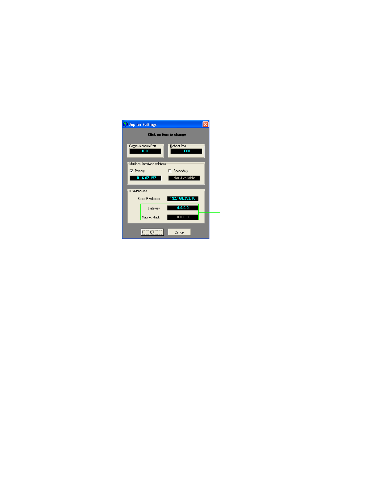
2. Select the Jupiter Settings option from the Tools menu (Tools> Jupiter
Settings). The Jupiter Settings dialog will then appear.
Figure 1. The Jupiter Settings Dialog
3. Enter the Subnet Mask and Gateway IP Addresses for your system. See
your System Administrator for this information.
Note Grass Valley recommends that you enter the IP address of your Jupiter PC
and use 255.255.255.0 for the Subnet Mask if there is no Gateway. However,
only enter this information if your System Administrator does not provide the
needed information.
4. Click the Ok button to apply the changes.
8 JUPITER — Release Notes
Page 9
Pro-Bel SW-P-08 Protocol
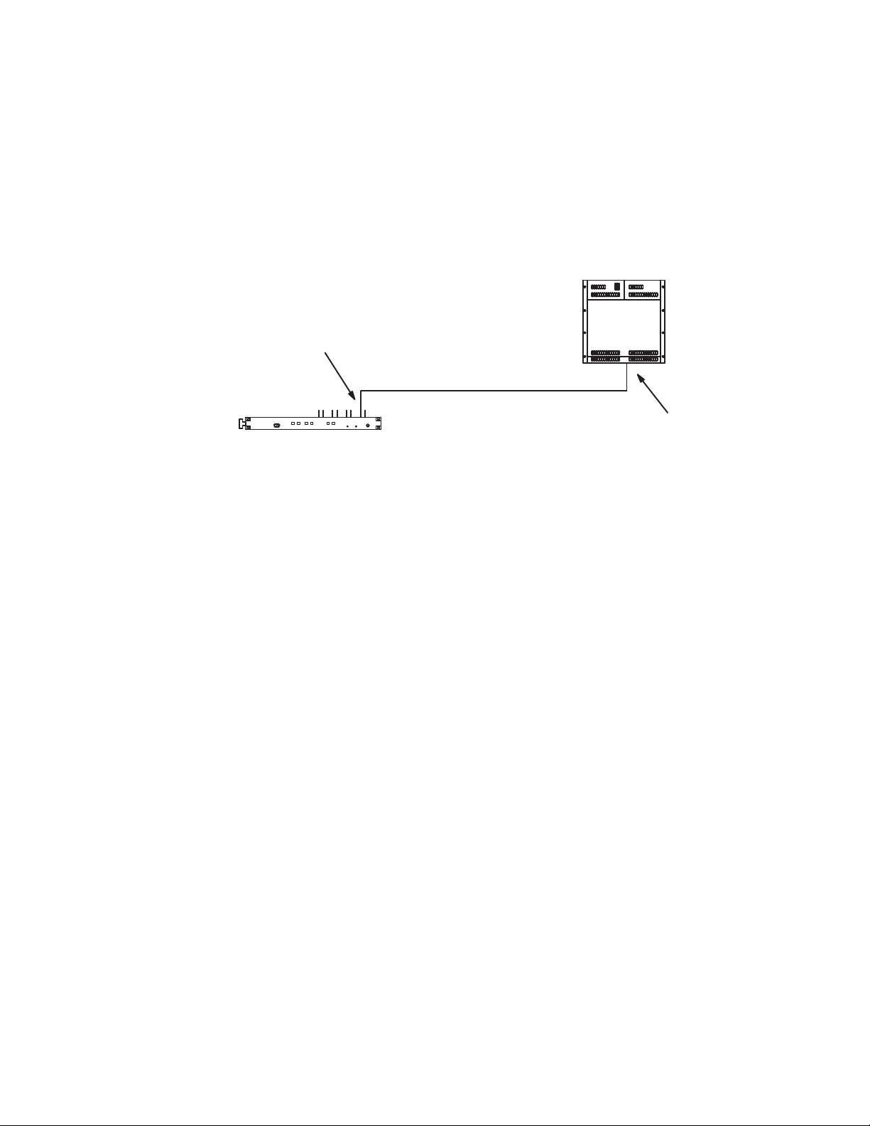
CM 4000
P8R or P08 protocol
“Hi speed serial” port
or
“Port 4”
Pro-Bel router
Any available serial port
The 7.9.0 version of the Jupiter system supports two new protocol drivers,
for AccuSwitch, that implement parts of the Pro-Bel SW-P-08 protocol. The
first driver is implemented as a standard Remote Router control interface.
The second driver is implemented as an Automation, or as a Control panel,
interface.
Figure 2. Pro-Bel SW-P-08 Router Switcher Setup
Pro-Bel SW-P-08 Protocol
This section will describe the needed setup and configuration steps to use
the Pro-Bel SW-P-08 protocol for:
• Jupiter Router control
• Remote Router control
Jupiter Router Control
You will need to configure the Jupiter CM-4000 or CM-4400 to use a Pro-Bel
SW-P-08 Router Control port. This is accomplished by adding entries in the
Serial Protocol and MPK Devices tables.
For steps to configure a CM-4000 or CM-4400 or modifying, compiling, and
validating a configuration set, see the CM 4000 Control Module or the CM4400 Control Module manuals.
Note These steps assume that the CM-4000 or CM-4400 has been configured
properly.
Entering Serial Protocol Information
You may need to modify the Configuration set that is currently active; if so,
Grass Valley recommends that you make a copy for editing before making
these changes.
For more information about modifying the Configuration set, please see
the CM-4000 or CM-4400 Control Module manuals.
JUPITER — Release Notes 9
Page 10
Version 7.9.0
Protocol
Baud Rate
Note On the Title bar of the Jupiter Configurator application you will see the name
of the Configuration set. Make sure that the configuration set that is opened
is the correct set that you want to change.
Follow these steps to enter or modify the Serial Protocol table:
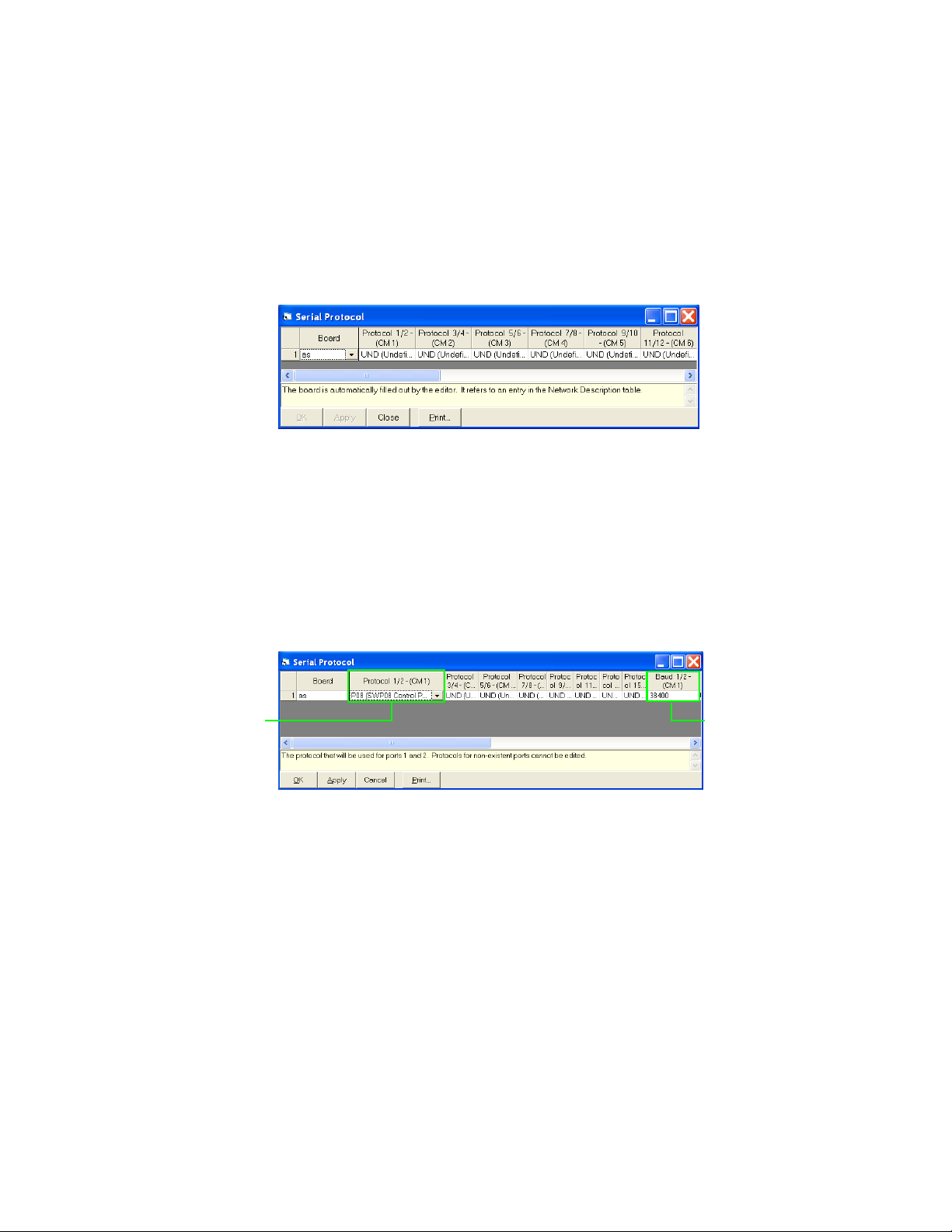
1. Select the Serial Protocol option from the Jupiter menu (Jupiter > Serial
Protocol). The Serial Protocol table will then open (Figure 3).
Figure 3. Example of the Serial Protocol Table
2. Double−click the protocol box that is associated with the Serial port. A
drop-down list will show the possible protocol types.
3. Select the P08 (SW-P-08 Control Panel) protocol.
4. Click anywhere else in the table to close the entry. The default Baud
rates will be selected automatically; however, the Baud rate may be
changed by clicking the drop down menu (Figure 4).
Figure 4. The P08(SW-P-08 Control Panel) Protocol on The Serial Protocol Table
5. Click the Apply button and then save your changes.
Note The serial line parameters are:
• 38400 Baud
•8 data bits
• No parity
• 1 stop bit
• The baud rate is adjustable
10 JUPITER — Release Notes
Page 11

Entering MPK information
You will need to make entries in the MPK Devices table for the port to associate the Input, Output and Level sets. The Device Type is Serial with a
Serial Input and an Output set. The level type is cp3000.
Note These steps assume that a Serial Input set, Output set, and a Level set have
already been configured. For steps to configure a CM-4000 or CM-4400 see
the CM-4000 or CM-4400 Control Module manuals.
Follow these steps to enter or modify the MPK table:
1. Select the MPK Devices option from the Jupiter menu (Jupiter> MPK
Devices). The MPK Devices table will then open.
2. Enter a name in the MPK Devices column.
3. Click the Device Type drop-down list and then select the Serial option.
4. Click the Board drop-down list and then select the preferred board.
5. Enter the Port number in the Port column.
Pro-Bel SW-P-08 Protocol
6. Select the Input Sets drop-down list and then select the preferred Serial
input set.
7. Select the Output Sets drop-down list and then select the preferred
Serial Output set.
8. Select the Level Sets drop-down list and then select the preferred Serial
Level set.
9. Click the Apply button and then save your changes (See line #5 in
Figure 5).
Figure 5. MPK Device Table
Pro-Bel SW-P-08 Protocol Commands
This section provides the command, and a description for the commands,
that are implemented to interface with a Studer Router switcher using the
JUPITER — Release Notes 11
Page 12

Version 7.9.0
Pro-Bel Pro-Bel SW-P-08 protocol. Both the normal and extended Pro-Bel
commands are supported.
You should be familiar with the Pro-Bel SW-P-08 commands before using
this information.
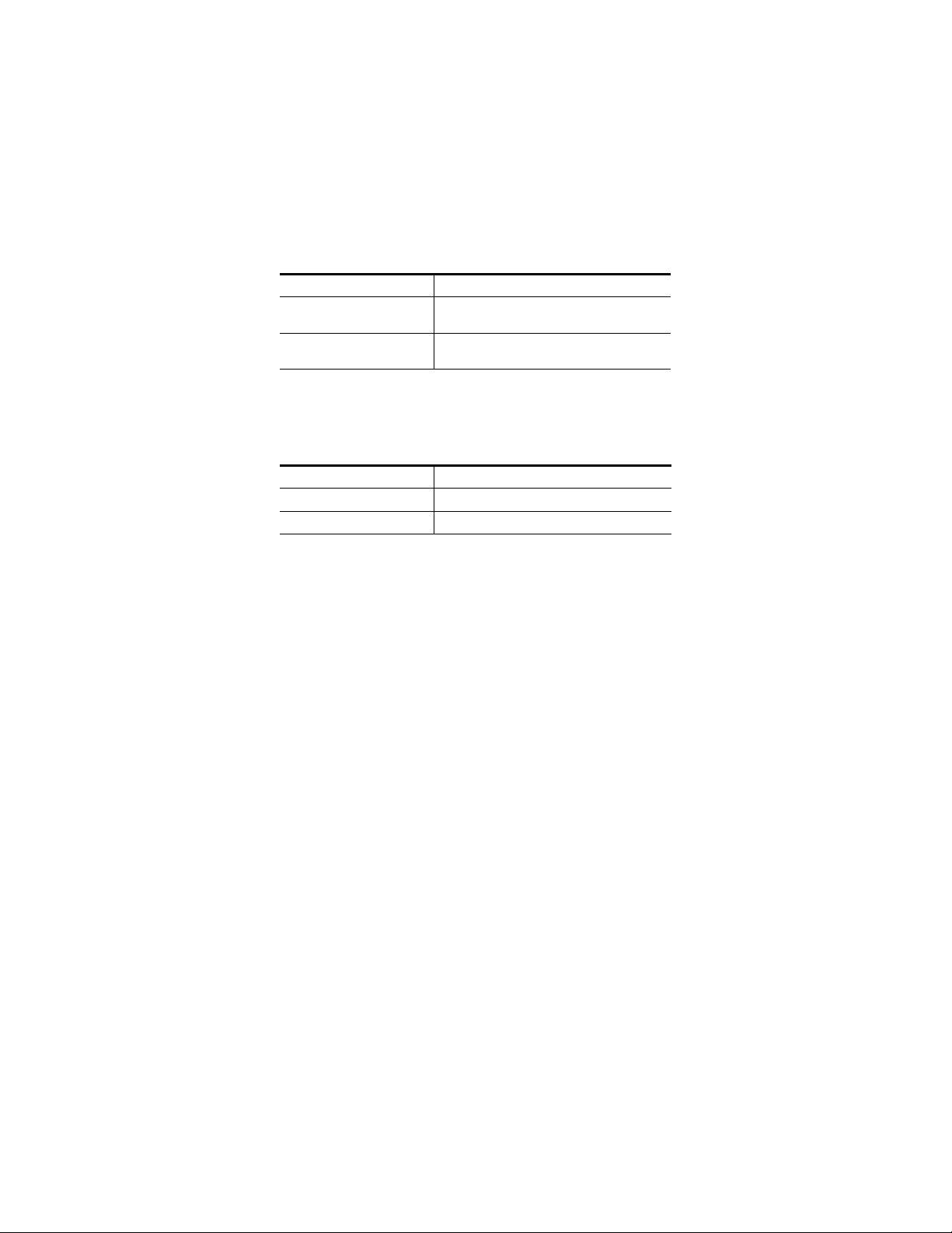
Table 1. Pro-Bel Pro-Bel SW-P-08 Protocol Commands
Command Description
Crosspoint Interrogate This command responds with a Crosspoint Tally message.
Crosspoint Connect This command responds with a Crosspoint Connected message.
In addition Jupiter accepts Crosspoint Connected messages and converts
them into Crosspoint Connect messages except that there is no further status response. This was done to update the Jupiter status from status messages sent from the Studer interface.
SingleSourceNameRequest This command responds with a SourceNamesResponse message.
SingleDestinationAssociationNamesRequest
Remote Router Control
Note You will need a specific Jupiter license key to enable the P08R option in the
Driver column of the Switcher Description table.
This interface will send the Crosspoint Connect message and will wait for
a matching Crosspoint Connected message to confirm the switch.
Pro-Bel’s Extended Crosspoint Connect and Extended Connected
commands are used when there are more than 1023 inputs or outputs.
Determining the Protocol Matrix and Level
When a Third-Party switcher of this type and a Grass Valley Crosspoint Bus
switcher are entered on the Switcher Description table, an offset of 100 can
be used to avoid having the same level numbers for both switchers. For
example, if you have two switchers, an Alpha Image and a Datatek.
The Jupiter name length is 8 characters but the protocol implementation
supports all the Pro-Bel lengths (FourChar, EightChar, and TwelveChar).
This command responds with a DestinationAssociationNamesResponse
message.
• A hardware level setting of “0” on the Alpha Image switcher could be
entered on the Switcher Description table as “100.” If the Pro-Bel
remote router also uses level “0,” it would be entered as “200” in the
PLvl field.
• A hardware Level setting of “1” on the Datatek switcher could be
entered on this table as “101.”
This offset eliminates the need to re-set existing level settings on the hardware.
The Protocol matrix and Level are both set by the Jupiter system’s Physical
level value, which ranges from 0 to 99. The matrix is the physical level
12 JUPITER — Release Notes
Page 13

Pro-Bel SW-P-08 Protocol
Physical
level
(PLvl) divided by 16. The protocol level is the remaining physical level
value from 16. The physical level is found on the Jupiter CM’s Switcher
Description table.
For example, in Figure 6 the Physical level value on row 7 is 102.
Figure 6. Physical Level on the Switcher Description Table
All values over 100 are offset by 100; hence, the Physical level value would
be 2. In this example the Protocol matrix value is: 0
For more information see Tab le 2.
Remote Router Values
As stated earlier, all Remote-Router Physical level values are offset. The
Pro-Bel SW-P-08 remote router physical level value is offset by 100. The fol
lowing table shows the Matrix and Level values for a given PLVL.
Table 2. Remote Router Values for Physical Level(0 - 99), Matrix, and Level
PLvl Matrix Level
00 0 36 2 4 72 4 8
10 1
20 2
30 3 39 2 7 75 4 11
40 4
50 5
60 6
70 7
80 8
90 9
10 0 10
11 0 11
12 0 12
13 0 13 49 3 1 85 5 5
-
PLvl Matrix Level PLvl Matrix Level
37 2 5 73 4 9
38 2 6 74 4 10
40 2 8 76 4 12
41 2 9 77 4 13
42 2 10 78 4 14
43 2 11 79 4 15
44 2 12 80 5 0
45 2 13 81 5 1
46 2 14 82 5 2
47 2 15 83 5 3
48 3 0 84 5 4
JUPITER — Release Notes 13
Page 14

Version 7.9.0
Table 2. Remote Router Values for Physical Level(0 - 99), Matrix, and Level
PLvl Matrix Level
14 0 14 50 3 2 86 5 6
15 0 15
16 1 0
17 1 1
18 1 2
19 1 3
20 1 4
21 1 5
22 1 6
23 1 7
24 1 8
25 1 9
26 1 10
27 1 11
28 1 12
29 1 13 65 4 1
30 1 14 66 4 2
31 1 15 67 4 3
32 2 0 68 4 4
33 2 1 69 4 5
34 2 2 70 4 6
35 2 3 71 4 7
PLvl Matrix Level PLvl Matrix Level
51 3 3 87 5 7
52 3 4 88 5 8
53 3 5 89 5 9
54 3 6 90 5 10
55 3 7 91 5 11
56 3 8 92 5 12
57 3 9 93 5 13
58 3 10 94 5 14
59 3 11 95 5 15
60 3 12 96 6 0
61 3 13 97 6 1
62 3 14 98 6 2
63 3 15 99 6 3
64 4 0
The above table will start over after 100.
Entering Serial Protocol information
The steps to configure Jupiter for Remote router control are similar to the
steps to control Jupiter. That is, adding entries in the Serial Protocol table.
Note These steps assume that the CM-4000 or CM-4400 has been configured
properly.
In most cases, you will need to modify the Serial Protocol set that is currently active; if so, Grass Valley recommends that you a copy for editing.
For more information, please see the CM-4000 or CM-4400 Control Module.
Note On the top of the Jupiter Configurator window on the title bar, you will see the
name of the Configuration set. Ensure that the configuration set that is
opened is the one that you want to change.
Follow these steps to enter or modify the Serial Protocol table:
1. Select the Serial Protocol option from the Jupiter menu (Jupiter> Serial
Protocol). The Serial Protocol table will then open (Figure 3).
14 JUPITER — Release Notes
Page 15

Pro-Bel SW-P-08 Protocol
Protocol
Baud Rate
Figure 7. Example of the Serial Protocol Table
2. Double−click the protocol box that is associated with the Serial port. A
drop-down list will show the possible protocol types.
3. Select the P8R (SW-P-08 Router Control) protocol.
4. Click anywhere in the table accept the entry. The Baud rates will be
selected automatically (Figure 4). The Baud rate can be changed by
clicking the drop-down list in the Baud rate column.
Figure 8. The P8R (SW-P-08 Router Control) Protocol on The Serial Protocol Table
5. Click the Apply button and then save your changes.
6. Compile and activate the Configuration set.
JUPITER — Release Notes 15
Page 16
Version 7.9.0
Pro-Bel SW-P-08 Interface Implementation Notes
P8R (SW-P-08 Router Control)
The P8R (SW-P-08 Router Control) driver will send the following:
Table 3. P8R(SW-P-08 Router Control) driver Sent Information
Message Value
CONNECT 2 (matrix=pLvl/16, level =pLvl%16 input <
1024 output < 1024)
CONNECT_EXT 130 (depending on the input and output >=
1024)
This P8R (SW-P-08 Router Control) driver will receive the following:
Table 4. P8R(SW-P-08 Router Control) driver Received Information
Message Value
CONNECTED 4
CONNECTED_EXT 132
When the P8R (SW-P-08 Router Control) driver is used, the following will
occur:
• The Commands that are not extended will truncate the Matrix and the
Level values to a 4 bit value. The Level value in the PLvl column of the
Switcher Description Table is converted into a unique Level value
between 0 and 100 (0 - 0x63).
• The Physical level (PLvl) value is then converted into a Pro-Bel SW-P08 Matrix and Level value. The Pro-Bel SW-P-08 level value is from 0 to
15 and the Pro-Bel SW-P-08 matrix value is from 0 to 6, which is the
physical level divided by 16.
• A Jupiter system TAKE command will send a Pro-Bel CONNECT message, which is confirmed when a CONNECTED message is received
immediately following the CONNECT message.
• The interface will re-send a CONNECT message up to three more times
after an error or if the CONNECTED response is not what was expected
to confirm the TAKE command.
• The protocol ACKS all messages that are received correctly even if they
are not implemented.
16 JUPITER — Release Notes
Page 17

P08 (SW-P-08 Control Panel)
The P08 (SW-P-08 Control Panel) driver will receive the following:
Table 5. P08 (SW-P-08 Control Panel) Received Information
Message Value
CONNECT 2
CONNECT_EXT 130
INTERROGATE 1
INTERROGATE_EXT 129
CONNECTED 4
CONNECTED_EXT 132
Single source name request 101
Single destination name
request
Single source name extended 229
Single destination name
extended
103
231
Pro-Bel SW-P-08 Protocol
The P08 (SW-P-08 Control Panel) sends the following:
Table 6. P08 (SW-P-08 Control Panel) Sent Information
Message Value
TAL LY 3
TALLY_EXT 131
CONNECTED 4
CONNECTED_EXT 132
Source name response 106
Destination name response 107
Source name response
extended
Destination name response
extended
234
235
When the P08 (SW-P-08 Control Panel) driver is used, the following will
occur:
• The control panel level value is a combination of the Pro-Bel SW-P-08
matrix and level values. The level is the matrix times 16 plus the level.
• The interface ACKS all messages that are received correctly even if they
are not implemented.
• The system responds to a CONNECT message with a CONNECTED
message only when the cross point is valid. Unsolicited CONNECTED
messages will be sent for confirmed TAKES to outputs in the control
panel set.
Commands are repeated up to 3 times when a NAK (error) occurs.
JUPITER — Release Notes 17
Page 18

Version 7.9.0
Physical Serial Interface
This section describes the pins of the Serial cable. The two Tables (Ta bl e 7
and Ta bl e 8) describe the configuration.
Figure 9. Serial Cable Pin-out
1
G
6
2
R−
7
R+
3
T+
8
T−
4
9
5
RS-422/485
6
7
8
9
RS-232 DTE
(female)
Table 7. Control Module RS-422/485 Female 9 pin Configuration
Pin # Configuration
1 GND
2 RX-
3TX+
7 RX+
8TX-
R
T
G
(male)
1
2
3
4
5
071827512_Probell-Serial connections
Table 8. PC RS-232 Male DTE pin Configuration
Pin # Configuration
5 GND
2 RXD
3TXD
18 JUPITER — Release Notes
Page 19

Remote PC Access is No Longer Supported
The Configure menu
has been reinstated
The File Server/
Remote PC button
has been reinstated
Remote PC Access is No Longer Supported
The Remote PC feature is no longer supported in Jupiter version 7.8.2 and
may not work as desired due to changes in the Microsoft Windows oper
ating system. Grass Valley has no control over the changes Microsoft implements. Furthermore, Grass Valley assumes no responsibility or liability for
any continued use of this feature; the user of this feature assumes all risk
and liability including, without limitation, lost profits, business interrup
tion, or lost information.
The Configure menu and the File Server/Remote PC button was removed in
the 7.8.2 version of Jupiter, this feature was reinstated to the JNS Control
Console in the 7.9.0 version.
Figure 10. The JNS Control Console
-
-
JUPITER — Release Notes 19
Page 20

Version 7.9.0
Spanning Tree Protocol
The Spanning Tree protocol is not supported in Jupiter and should be disabled or have Rapid Spanning Tree Protocol (RSTP) enabled. All ports
should be configured to the auto-negotiate mode.
Using the Spanning Tree protocol will cause port latency on the switch
when a device reboots and this will cause Jupiter network problems.
Grass Valley assumes no responsibility or liability for use of the Spanning
Tree protocol; the user of this protocol must assume all risk and liability as
mentioned previously in
Remote PC Access is No Longer Supported on page 19.
20 JUPITER — Release Notes
Page 21

Upgrading to 7.9.0
Caveats
Please read the following caveats before starting the upgrade procedure.
During this upgrade procedure:
• All switcher status will be lost. To restore status, make note of the status
of all outputs before starting the upgrade and re-take all switches. Or,
you can use Router Save/Restore to restore status on Grass Valley (GV)
routers.
• All memory on all Jupiter control system boards will be cleared after
the installation and download process. The memory is cleared due to a
mandatory “pmemclear“ command.
• All configuration sets will need to be recompiled.
Upgrading to 7.9.0
Equipment Required
GV-supplied PC 3000 (F7-029500-121) file server or a PC with the following
minimum requirements:
• Windows XP Professional - SP2 (English version)
• 2 GHz Pentium processor
•2 GB of RAM
• 125 MB of Hard disk space for the Jupiter application
• Intel or 3Com Ethernet LAN card
• Keyboard and mouse
A minimum resolution of 1280 X 1024 and 32 -bit color PC monitor setting
is recommended for proper display of the Jupiter Soft Panel and VSD
screens. The Appearance font size on the Display Properties dialog (Con
trol Panels> Display> Appearance: Font size drop-down list) should be set
to Normal. Selecting either the Large or the Extra Large Fonts option will
cause application display problems.
Software Required
-
Installation of the Jupiter 7.9.0 release is only supported on the English
version of Windows XP Professional SP2 or later. Windows Firewall and
any Anti-Virus Firewall must be disabled to allow the Bootp, TFTP, and JNS
applications to operate properly.
JUPITER — Release Notes 21
Page 22

Version 7.9.0
Materials Supplied
The information shown below in the following tables are supplied with the
release.
Jupiter Software upgrade for:
JUP-SW 2500 (Jupiter LE for VM/SI-3000), or
JUP-SW 3100 (Jupiter Plus for VM-SI-3000), or
JUP-SW 3500 (Jupiter XPress for CM-4000),
JUP-SW 4400 (Jupiter AccuSwitch for CM-4400), or
JUP-SW 4000 (Jupiter AccuSwitch for CM-4000):
QTY Description Part number
1 Software, CD, Jupiter v7.9.0 063809315
1 Release Notes 071827513
Optional Materials
The following manuals and optional software are also available:
• Application specific software licenses (refer to Section 1 of the Jupiter
• Jupiter VM/SI-3000 Installation and Operating Manual (VM-3000)
• Jupiter CM-4000 Installation and Operating Manual.
• Jupiter CM-4400 Installation and Operating Manual.
• L, S, and LCD Series Jupiter Control Panels Manual. (Manual available
• AccuSwitch Soft Panels and Visual Status Display
Software Update
CAUTION During the software update your Jupiter system will be taken off-line for a
Installation and Operating manuals for more information)
online-contact Technical Support for more information.)
short time while the control boards (CM-4000 and CM-4400) are updated.
Existing matrix cross-points will remain selected, but source to destination
changes will not be possible while the control boards are off-line.
Contact Grass Valley Customer Support if you have any questions
regarding this software update.
22 JUPITER — Release Notes
Page 23

Note Read these instructions carefully and follow all the steps exactly to help
ensure that your update goes smoothly.
Update Only Existing Jupiter Systems
This procedure is for updating an existing Jupiter system that has been previously installed, completely configured, and is operating correctly. New
Jupiter systems ship from the factory with the latest version of software
pre-installed. New systems do not need their software updated. However,
new Jupiter systems will need to be configured to operate at your facility.
Software Update
JUPITER — Release Notes 23
Page 24
Version 7.9.0
Installing the Jupiter Software Components
Updating a Previous Installation
The update procedure is a two-step process. The first step will be to remove
the previous version of the Jupiter software. The second step will then start
the installation of the latest version of the application.
Removing the Previous Version
The Installation program will check to see if an earlier version of Jupiter is
installed on the computer. The earlier version will be removed before the
latest version will be installed. You will need to start the Installation
program again after the earlier version has been removed.
To start the update process and remove the previous version:
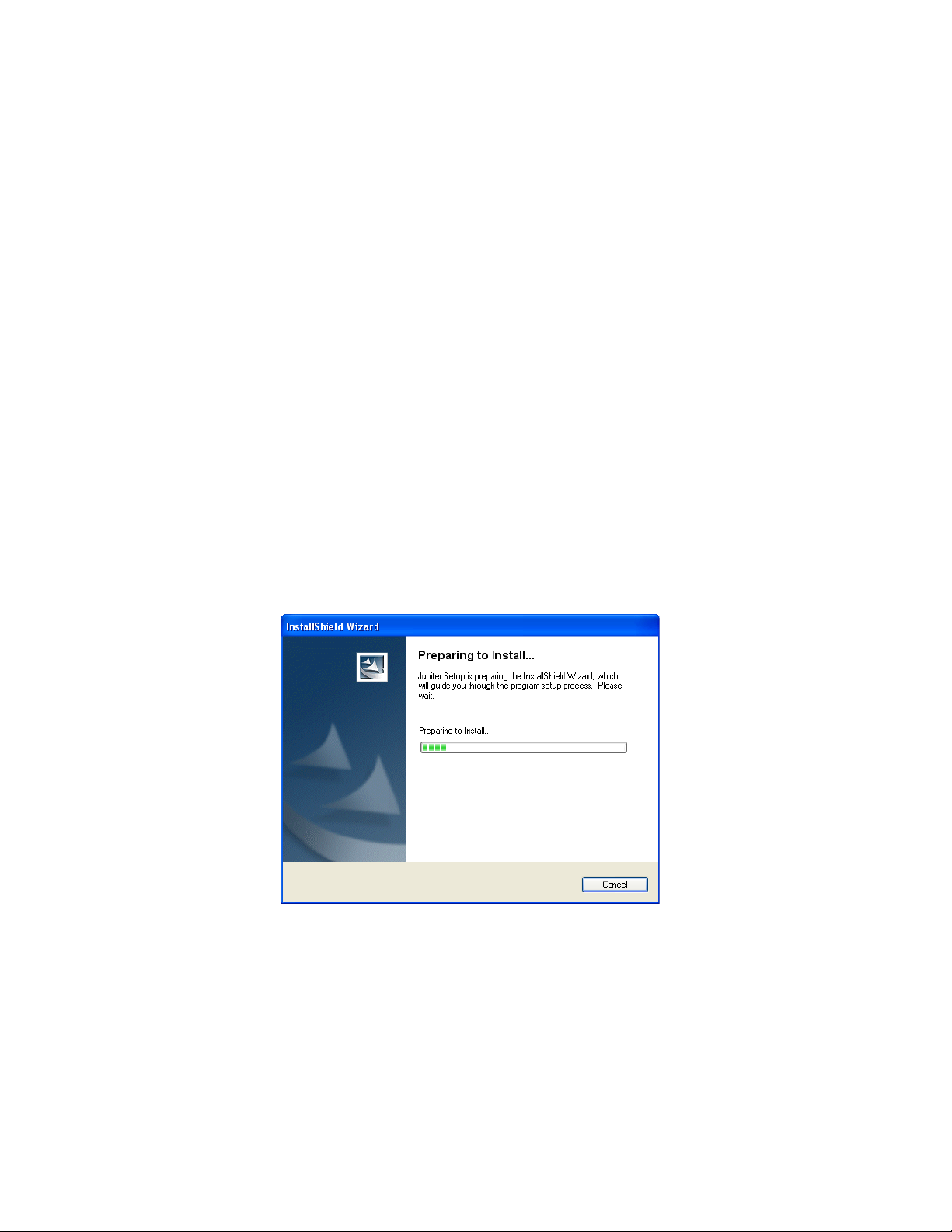
1. Insert the Jupiter System Software CD into the PC. If the Installation
Program doesn’t start up automatically, double-click the
on the CD. The Preparing to Install screen will then be displayed
(Figure 11).
Setup.exe icon
Figure 11. Preparing to Install Screen
24 JUPITER — Release Notes
Page 25

Installing the Jupiter Software Components
The Welcome - Remove the program screen will then appear after a few
minutes (
Figure 12. Welcome - Remove the Program Screen
2. Click the Next> button. The Setup Status screen will then appear
Figure 13. Setup Status Screen
Figure 12).
(Figure 13).
The previous version of the application will then be removed.
JUPITER — Release Notes 25
Page 26

Version 7.9.0
When the removal of the application has been completed, the Maintenance
Complete screen will then appear (
Figure 14. Maintenance Complete Screen
Figure 14).
3. Click the Finish button. The InstallShield Wizard application will then
close.
You can now install the latest version of Jupiter.
Installing the Latest Version
Note To help ensure any hidden activity is stopped you should restart the com-
puter.
Before you begin the installation process, make sure that you close all
Jupiter programs on the configuration PC and disable any virus protec
tion programs or firewalls.
-
26 JUPITER — Release Notes
Page 27

Installing the Jupiter Software Components
Follow these steps to start a new installation Process:
1. Insert the Jupiter System Software CD into the PC. If the Installation
Program doesn’t start up automatically, double-click the
on the CD. The Jupiter Installation Welcome screen will then be
displayed (Figure 15).
Figure 15. Jupiter Installation Welcome Screen
Setup.exe icon
2. Click the Next > button. The Customer Information screen will then
appear (Figure 16).
Figure 16. Customer Information
3. Enter your User Name, Company Name, and the Soft Key in their
respective fields.
Note The Soft key can be found on the plastic case that the Jupiter CD was shipped
with.
JUPITER — Release Notes 27
Page 28

Version 7.9.0
4. Select the Anyone who uses this computer (all users) radio button.
5. Click the Next > button. The Software License Agreement screen will
then appear (Figure 17).
Figure 17. License Agreement
6. Click the Yes button to accept the license agreement. The Setup Type
screen will then appear (Figure 18).
Figure 18. Setup Type Screen
7. Select the preferred type of installation and then click the Next > button.
The Question dialog will then appear (Figure 19). You will need the
Part Number Revision letter on the MCC-3500 Control Panel Logic
board. For example, in figure below the part number is correct.
28 JUPITER — Release Notes
Page 29

Installing the Jupiter Software Components
Figure 19. Question Screen
8. Click the Yes button if the letter is correct or if you are not using the
Saturn Master Control system. The Choose Destination location screen
will then appear (Figure 20).
Figure 20. Choose Destination Location Screen
9. Browse to the Destination folder of your choice and then click the
Next > button. The Enter Network Information dialog will then appear
(Figure 21).
Figure 21. Enter Network Information Screen
10. Select the IP address for the Network card that will communicate with
the Jupiter system.
JUPITER — Release Notes 29
Page 30

Version 7.9.0
Note Consult with your Network administrator if you do not know the network
values to enter.
• If there is more than one Network card installed, all the cards will
appear in the dialog window.
• Enter the Port information in the respective fields
11. Enter the IP address for the Controller boards in the required field and
then click the
Note You must set the Subnet Mask and Gateway IP addresses to run the 7.9
version of Jupiter on the CM-4400. See Setting the Subnet Mask and Gateway
IP Addresses on page 8 for more information.
Next> button.
Using DHCP
If you are using DHCP, that is your IP address is not static, you will see
the following Question dialog (
Figure 22. Question Dialog
Figure 22).
Note It is strongly recommended that you use a Static IP address. Using DHCP
may cause configuration problems.
If you want to correct the IP address, click the Ye s button. The Choose
Destination Location screen will then appear.
30 JUPITER — Release Notes
Page 31

Installing the Jupiter Software Components
Using a Static IP Address
The Start Copying Files screen will appear (Figure 23).
Figure 23. Start Copying Files Screen
1. Review the Current Settings and then click the Next> button. The Setup
Status screen will then appear (Figure 24).
Figure 24. Setup Status Screen
When the Installation process is completed the InstallShield Wizard
Complete screen will then appear (
Figure 25).
JUPITER — Release Notes 31
Page 32

Version 7.9.0
Figure 25. InstallShield Wizard Complete Screen
2. Click the Finish button. The installation process is now completed.
32 JUPITER — Release Notes
 Loading...