

Page 1

GGeettttiinngg SSttaarrtteedd GGuuiidde
e
Page 2

Jupiter Facility Control System Version 6.2
Getting Started Guide
Manual part no. 04-045707-003 Rev E
March 16, 2004
(c) 1996,1998, 2001, 2004 Thomson Broadcast and Media Solutions, Inc.
All rights reserved. All specifications subject to change without notice.
For customer service, please call (800)
concerning this manual, please contact: Technical Publications Department,
P.O. Box 30816, Salt Lake City, Utah 84130-0816. Phone: (801) 972-8000.
Fax: (801) 977-1602. Email: SLCtechpubs@thmulti.com
Trademark notice
Jupiter and Venus are trademarks of THOMSON. WINDOWS is a trademark of Microsoft, Inc.
547-8949.
comments or questions
For
Page 3

Introduction
Power, flexibility, and reliability—
These words describe the Jupiter
Control System best. Unfortunately,
such features make for a somewhat
intimidating and lengthy manual.
This document is designed to
simplify the set up process—adding
ease-of-use to the long list of Jupiter’s
state-of-the-art features.
1
Page 4

Page 5

GGeettttiinngg SSttaarrtteedd wwiitthh HHaarrddwwaarre
e
To the customer:
Someone once said that a picture is worth a thousand words. Concerning the Jupiter
set up, this statement is certainly true. The diagrams below should make the
hardware set up quite simple.
Figure 1. Connection to Philips/Thomson routing switchers
For jumper and
switch setting
information, refer
to the hardware
manual supplied
with the switcher.
15-pin CC 2010 Matrix (crosspoint bus) data cable
Binary protocol
Crosspoint bus port
SDR 400
Mars
Venus
Trinix
VM 3000
Control
Processor
LAN
House T/C
(Optional)
House sync required for
vertical interval switching.
3
Page 6
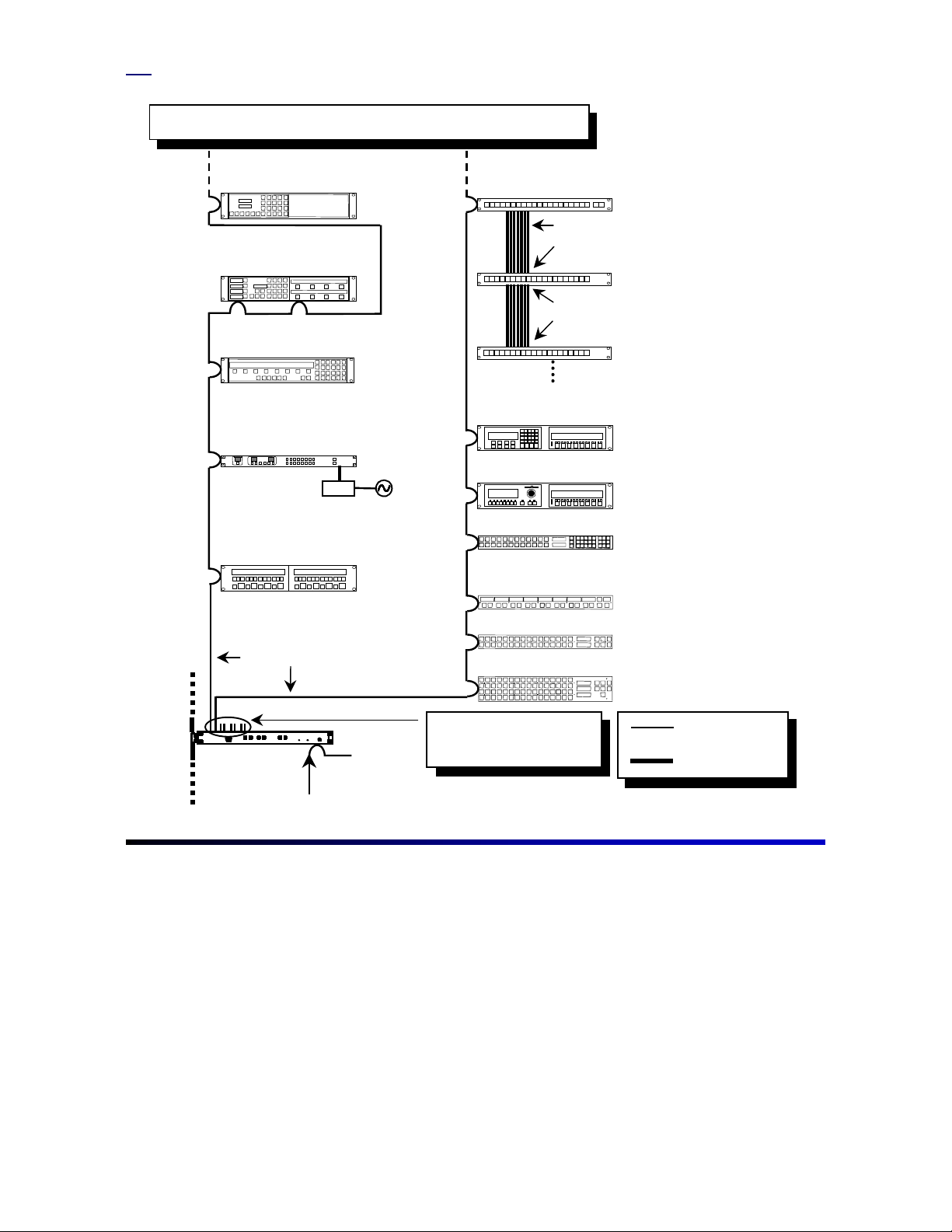
Figure 2. Control panel installation
Each port on a VM/SI 3000 has a recommended maximum quantity of control
panels. Refer to section 2 of the Installation and Operating Manual.
CP 3830 Control Panel
CP 3808 with CP 3809 expansion panel
CP 3800 Control Panel
CP 300 Series Control Panel
PS-20
MC 3010/2 Dual 4-Machine Control Panel
CP 3020 Pushbutton Control Panel
12 in. ribbon cable supplied with CP 3021
“Input" connector
CP 3021 Pushbutton
Expansion Panel
“Output" connector
“Input" connector
CP 3021 Pushbutton
Expansion Panel
Maximum of 4 CP 3021s
CP 3000 Switcher Control
with expansion panel
MC 3000 Machine Control
with expansion panel
CP 3824 Control Panel
CP 3810 Control Panel
CP 3832 Control Panel
Serial (MPK) Cables
CP 3864 Control Panel
VM/SI 3000
(VM 3000 shown)
Port connections are defined
in the MPK Devices table.
Refer to step 10.
Sync Reference
9-pin Serial data
cable
LAN cable
4
Page 7
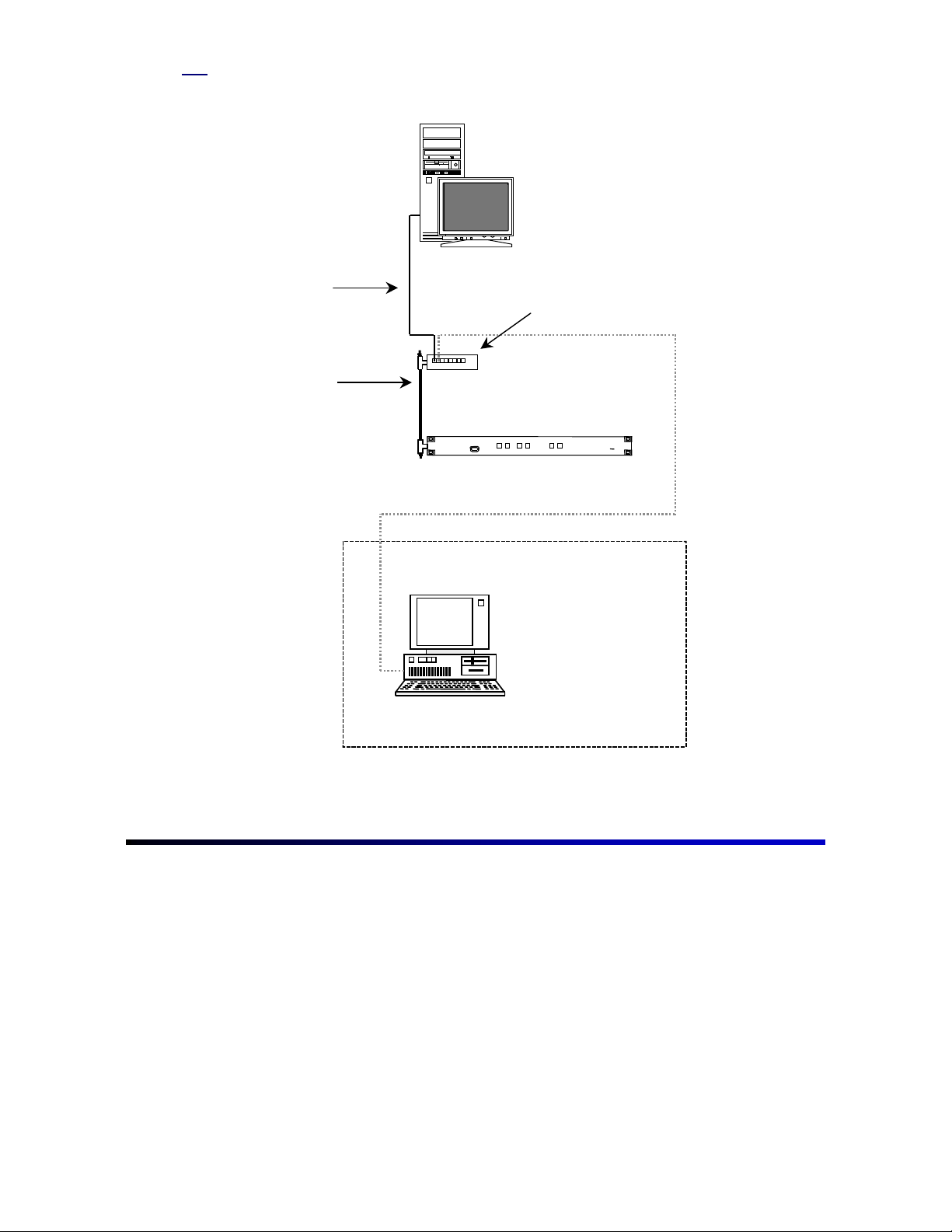
Figure 3. PC-to-VM connections
JNS File Server
with network card
10baseT LAN Cable
10base2 LAN Cable
VM/SI 3000
Control Processor
Jupiter Network Hub with BNC
and RJ45 connections
JNS Remote PC
with network card
5
Page 8

GGeettttiinngg SSttaarrtteedd wwiitthh SSooffttwwaarre
To the customer:
Due to the complexity and power of the Jupiter software, Thomson recommends
proceeding in the steps described below. Before proceeding, look through and
familiarize yourself with the Jupiter Control System Installation and Operating
Manual, part number 04-045707-002. An electronic copy is provided with the Jupiter
software.
Remember to program the system in small steps, validate tables, compile
often, and regularly backup working configuration sets.
Step 1
If the Jupiter Control System was purchased with a Venus, Triton, or Trinix router, a
factory-configured set will be provided. In such a case, the control system has
already been programmed with the factory set and will give its user numeric control of
the switcher by simply connecting the control panels and routing switcher according
to the drawings in the Documentation package. The programming is in flash memory
and no Jupiter programming is needed to obtain simple numeric switching. See the
Hardware Installation section of the Jupiter manual for details.
e
Note
Serial data cables for interconnecting control panels can be purchased from Thomson under the
following part numbers:
01-048591-001 (1 meter length)
01-048591-004 (4 meter length)
01-048591-008 (8 meter length)
01-048591-016 (16 meter length)
01-048591-032 (32 meter length)
The consumer can also build serial cables. See the Serial Data Cables subheading in Section 2
of the Jupiter manual.
Step 2
If the computer was purchased with a router from Thomson Multimedia Broadcast
Solutions, the Jupiter software and factory-configured set will already be installed. If
loading Jupiter for the first time, refer to the Field Engineering Bulletin for installation
instructions (the computer must be equipped as described under the Equipment
Required section of the FEB).
6
Page 9

Step 3
Go to the Windows desktop, click “Start > Programs > Jupiter Network Suite.” After
JNS opens, click the “Connect” button under JNS servers and wait for the computer
to complete its connections. Click “JNS Tools” in the toolbar, then click “Configuration
Editor.” This will open the Jupiter Configurator.
Note
The control system should be operational by making the connections detailed in the factory
Documentation package. If for some reason the flash memory has been corrupted, Thomson
recommends downloading the factory-configured set at this time to verify basic numeric
operation of the control system and router; the system can then be functional for wiring checkout
while more detailed sets are constructed. See the following steps to correctly download this set.
At this point, one of four scenarios may have occurred:
1. Jupiter, the file server, and router were purchased through Thomson.
2. Jupiter and the router were purchased through Thomson, but the file
server was not.
3. The Jupiter Configurator is being upgraded.
4. Jupiter was purchased without a routing switcher.
Go to the appropriate subheading of this step for the corresponding scenario.
Scenario 1
A custom set should be immediately available on the computer’s hard drive. Click
“File > Open” to open the factory-configured set. Copy the set to a new file name as
described at the end of this step.
Scenario 2
The set will be on a 3.5” floppy disk. To retrieve the set from the floppy, click “Tools >
Unzip Configuration Set.” This will open a standard Windows Explorer dialog box. In
the Toolbar of the dialog box, click the button that has a picture of a folder with an up
arrow on it. Continue to click this button until the floppy drive appears in the file
selection box. Double click the floppy drive in the main window, then double-click the
file that resembles the name of the station. Click “File > Open” to open the factoryconfigured set. Copy the set to a new file name as described at the end of this step.
7
Page 10

Scenario 3
If upgrading, the set used under the old configurator should be immediately available
through “File > Open” without unzipping the set.
Scenario 4
An entirely new set will need to be built. In this scenario, continue to work through
this Getting Started Guide since it is designed to familiarize the user with the basics
of the Jupiter software. However, working through section 5 of the Jupiter Installation
and Operating Manual will be necessary to successfully build a set.
Copying a set to a new name
Upon opening the set, copy the set to a new name. To do this, click “File > Save As.”
Give the set a new name. Thomson recomments naming the set 1 digit higher than
the original as in the example below. In this manner, the previous set is still available
in case errors are made on the new set.
Example:
Original factory-configured set: KXYZ-TV
New configuration set: KXYZ-TV1
Repeat this process for each modification session so that the old reliable set will
remain available.
Note
8
Although not recommended, if downloading the factory-configured set is not wanted, skip the
next step and proceed to step 5.
Page 11

Step 4
Check for errors in the set by clicking “Tools > Validate All Tables.” After finishing
validation and correcting the errors, open the compiler by clicking “Tools > Compile.”
Following the compile, return to JNS, click “JNS Applications” in the toolbar, then
click “Control Center.” When the Control Center opens, the configuration tab should
already be selected.
Check to see that the On Activation option is set to “Select and Reboot.” Select the
new set and click Activate. If the Control Center was open prior to the compile,
clicking Refresh List may be necessary if the newly compiled set does not appear.
Downloading will begin and a red LED alarm will illuminate on all devices connected
to the LAN. Make certain that the control panels are connected to the factoryprogrammed ports and have the appropriate protocols. See Documentation package
included with this document or look in the Serial Protocol table (step 6) and the MPK
Devices table (step 10) to see where the control panels are programmed to connect.
The VM 3000 should respond with the alarm LED illuminating and occasionally
blinking, indicating the reception of data. After a period of time (approximately up to 1
minute), the control panels should change from the “device not connected” message
to valid switcher status.
9
Page 12

Once the set has been downloaded, attempt to make a few switches. For control
panel operating instructions, refer Section 6 in the Installation and Operating Manual
for the particular control panel. If the system does not perform the switches, work
through the checklist below.
Troubleshooting Checklist
If the system does not go on-line or switch properly, go through the following
checklist and verify the correct settings or connections.
1. Control panels are connected to the proper ports with the correct
protocols as defined in the MPK Devices and Serial Protocol tables.
2. The control panel cables are pinned correctly (if self-made). Each
twisted pair in this cable
3. Black burst or sync has been connected to the VM 3000s.
4. The VM 3000 rotary switches on the top of the board are set to “00.”
5. CC 2010 (crosspoint bus) cables are connected from the VM 3000 to
the routing switchers.
6. The LAN cables are properly connected.
!
All BNC LAN connections are made and terminated with 50-ohm
terminators at each end. LAN cable is 50-ohm type cable. Avoid
5 meter lengths. Minimum length should be 20 inches.
!
All twisted pair 10baseT using RJ45 connectors for the CM 4000
are connected to the Jupiter network hub.
must
be individually shielded.
10
7. CM, VM, and SI addresses match the entries in the Network
Description table (see step 5).
8. Control panel addresses match the entries in the MPK Devices table.
9. Check the Switcher Description table and verify that the physical
level assignment coincides with the levels to which the switchers are
set. The switchers will have a sheet attached describing their levels.
Also, the Documentation package will describe the levels of the
switcher.
Page 13

Step 5
After the set has been downloaded and the system is operational, the Jupiter system
is now ready to be customized.
Note
If a Saturn Master Control switcher is present, Thomson recommends programming it after the
Venus and Jupiter are programmed and operational. The Saturn requires the switcher to be set
up correctly for it to function properly.
Be certain that the copy of the factory-configured set is the selected set. With the
mouse pointer, click “Jupiter > Network Description.” Skip the Password table for now
(if password levels are needed, they can be entered later).
At this time, the names of the VM 3000, SI 3000, and CM 4000s can be changed. If
changes are made to these names, changes will automatically be made in other
tables, such as Serial Protocol, Switcher Description, and MPK Devices. These
tables are described later in this document.
Having been entered at the factory, the board addresses should be correct. These
device addresses are labeled on the back of the VM 3000s, SI 3000s, and other
control boards and should be double-checked for accuracy.
download without these being correct.
After changes are made and the data is
The system will not
satisfactory, close this window by clicking OK.
11
Page 14
Step 6
Step 7
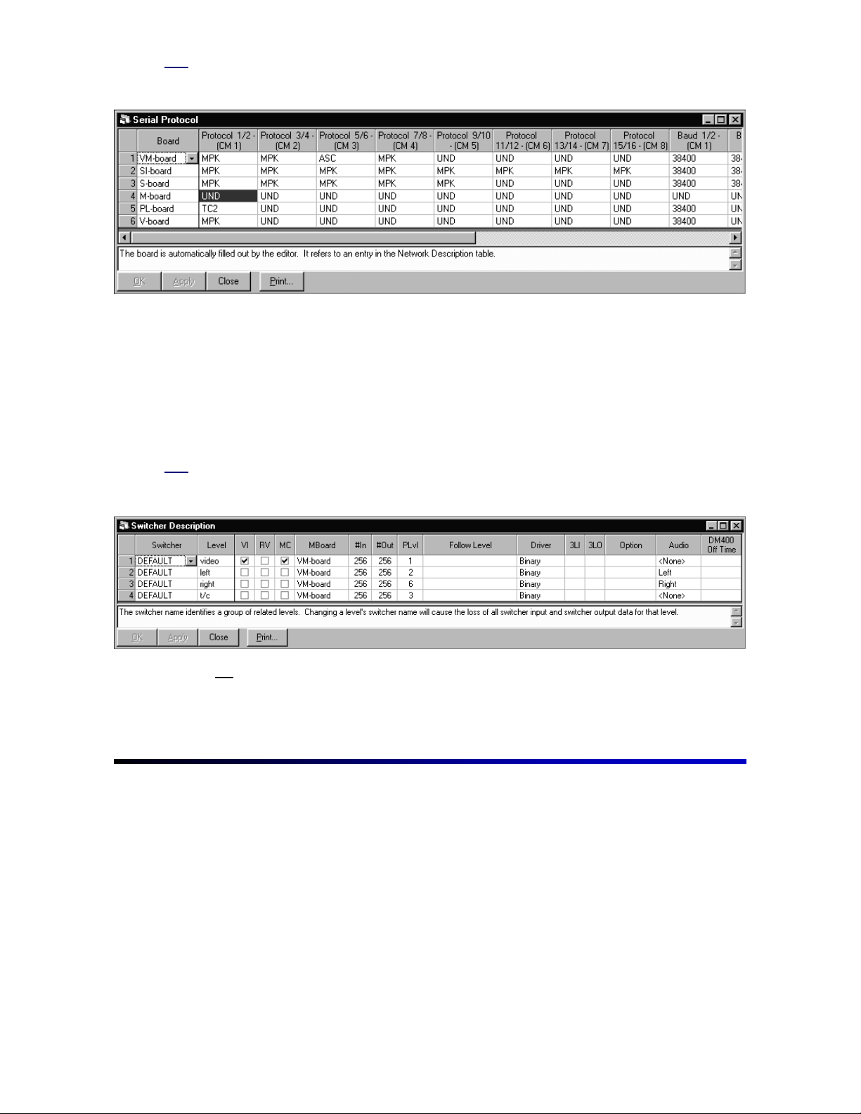
Next open the
Serial Protocol table
:
The devices described in the Network Description table appear here also. This table
sets up the type of devices that will be connected to the VM 3000, SI 3000, and CM
4000 ports. The factory configuration will probably contain all MPK entries. (MPK =
message per keystroke; this protocol is for all Thomson control panels.) Changes can
be made at this time, but keeping the system simple at this stage is the best advice.
Return later to add more complicated devices. Close this window by clicking OK. See
the Serial Protocol subheading under section 5 of the Jupiter manual for more details
about this table.
Next open the
Switcher Description table
:
12
Note
Changing switcher names or level names may cause data in the
to be lost.
tables
Switcher Input and Output
Page 15

Step 8
The factory-configured set will usually contain all switcher levels with the name of the
switcher (i.e., VENUS, TRINIX, TRITON, MARS, etc.), otherwise it will have a
switcher name of
DEFAULT
. Once again, making minimal changes to this table at
this time is advised. Possible changes may be to switcher names or level names.
More involved customizing of this table can be done in later steps.
(Thomson does
not recommend changing the switcher names if the Switcher Input and Output
tables have already been customized.)
When finished, click OK. See the Switcher
Description subheading under section 5 of the Jupiter manual for more details about
this table.
Open the
Switcher Input table
:
The factory-configured set will contain numeric representations for all source
designations. Enter the mnemonic names for the sources. Note that a switcher will
have several levels associated with it and columns of numbers for each level (the
column headings are taken directly from the Switcher Description table). These are
“crosspoints-to-switch” numbers and can be modified at this time if necessary.
Example:
In this example, “BARS” will switch crosspoints 000 for all the levels.
13
Page 16

Step 9
Example:
In this example, “BARS” will only switch crosspoints 000 video and left and right
audio since no entries were made to SDV, AES, and time code.
Example:
In this example, “BARS” will switch crosspoints 000 for all levels except time code,
which will switch input 030 crosspoint.
Open the
Switcher Output table
:
Note that the column headings here (except for Name, Security, S-T, and Password)
were also taken directly from the Switcher Description table. As in the previous table,
assign mnemonic name associations to the destinations. At this time, leave the
security board S-T and password entries blank in order to minimize the complexity at
this stage. If an output password protection is needed, it can be added later. Refer to
section 5 of the Jupiter manual for more details. Click OK to exit this screen.
14
Page 17

Step 10
Example:
In this example, “VTR1” will only receive video, left audio, right audio, and time code.
Example:
In this example, “MON1” will only receive video since no entries were made to left,
right, SDV, AES, and time code.
If control panels other than CP 3000s or CP 3800s are being used, refer to the
subheading in section 5 of the Jupiter manual pertaining to Control Panel Sets. Upon
completing the input, output, and level Control Panel Sets, return to step 10 and
continue.
Open the
MPK Devices
table:
The factory-configured set will contain all control panels with numeric input, output,
and level sets, which directly refer to the numeric entries in the Switcher Input and
Output sets as well as the levels defined in the Switcher Description table. At this
stage, setting up only a few control panels is recommended, preferably at least one
of these being a control panel that can control the entire matrix, such as a CP 3000,
or a CP 320. Print the contents of the MPK Devices table (see “Printing” in section 5
of the manual), then delete the control panels that will not be programmed—such as
those for machine control and tally. Clicking the row number in front of the control
panel will select the entire row. Press Delete.
15
Page 18

Two reasons for approaching the programming process this way are: First, setting up
a minimal amount of data for the first encounter with Jupiter will minimize
troubleshooting and also make it easier for Thomson technical support to help,
should problems arise. Second, control panels using numeric inputs and outputs will
not compile if the Switcher Input and Output tables have been changed to mnemonic
designations in the Switcher Input and Output tables.
After deciding on which control panels to set up for this stage, rename them by
double-clicking the device name to be changed if desired. Enter the new name,
naming them for the particular location where they will be in service. For example, if a
panel was designated to be used in Studio A, naming it “STUDIO” may prove to be
useful. For device type, move to the device type box, click the drop-down menu, and
make the appropriate selection from the list.
The next box (“Expansion”) is for control panels with an expansion panel; check the
box if this particular type is present, or leave it unchecked for all other panels.
Assign a VM 3000, SI 3000, or CM 4000 and a port to which this panel will connect;
the control panel must be physically connected to the port being assigned. Also, note
that this may be different than the port to which the panel is connected for the factoryconfigured set. If so, proper reconnection of the control panels must be made prior to
downloading this set. The port also must be set up to be an MPK port in the Serial
Protocol table.
Assign the appropriate input, output, and level sets. Each control panel can use a
different set or use a common set depending on the desired customization of the
access to the routing switcher. Do not program Sequence Sets or Overrides at this
time—this can be done later if necessary.
16
Note
The control panels might now be assigned to different ports than they were with the factory
configured set. The correct connections need to be made if this applies.
Note
Different types of control panels cannot use the same Input and Output sets. CP 3000 and CP
320 panels must have different set types created for them. However, copying a set and
modifying it to match the panel can save much time. Refer to section 5 of the Jupiter manual
under “CP Input Sets—Copying a CP Input Set for Use with a Different Panel Type” for more
information.
Note
The above description applies to CP 3000-type panels. Refer to Section 4 of the Installation and
Operating Manual for specific control panels.
Page 19

Step 11
Step 12
Note
Having accurate data, valid control panel address numbers, and appropriate control panels
connected to the correct ports is imperative. Studying the Jupiter manual for any peculiar
programming needs to make this table work is important.
At this point, enough data is available for the set to provide functional switcher control
even though many of the other tables have not been completed. Check for errors by
selecting “
compile the set by clicking “
about any problems that it might find while trying to compile. If the
Tools > Validate All Tables
Tools > Compile
,” and correct any errors that appear. Now
.” The compiler will give messages
compiler
identifies
errors, fixing the problem is imperative for a successful download even if validating
the tables identified no errors. With a little patience, the errors can be corrected and a
successful compile can be made; this step is one of the main reasons for keeping the
programmed data simple to this point.
Now that the set has been compiled, download the set and check that proper
crosspoint switches are made for what has been programmed. Return to the Jupiter
Network Suite and click “JNS Applications in the toolbar, then “Control Center.” The
screen will look like that in step 4.
Refer to step 4, which describes proper downloading, including the checklist to go
through if the download is not successful (see CP 3000 operation in the Jupiter
manual for additional help on control panel operation). The correct status should be
returned and everything should be functional to this point if programmed correctly.
Note
Note
If obtaining a successful download was not possible and the factory-configured set downloaded
and was functional, then the recently built set has a problem. It may be a problem that was not
detected by the validation process or the compiler. Troubleshooting the data entered is
necessary and the set must be validated by a successful download indicating that everything is
working before programming any more data. At this stage, troubleshooting will be much easier. If
the factory set has not been downloaded, Thomson recommends performing a download with
the factory set and verifying that all the hardware is functional. Refer to steps 1 through 4.
In some cases, it may be necessary to connect a probe terminal to the VM 3000 to aid customer
service in troubleshooting. See Appendix C of the Jupiter manual (“probe connections and
protocol”).
17
Page 20

Step 13
Congratulations! The set is working and ready to have additional programming. If
additional programming is desired, copy the newly compiled and downloaded set and
name it one digit higher.
Example:
New set: KXYZ-TV1
Copy of the new set: KXYZ-TV2
Step 14
Note
Using a modular means of programming is extremely important. Although set “KXYZTV1” works, leave this as is and add an additional block of data to “KXYZ-TV2,” which is
an exact copy. In this manner, set KXYZ-TV1 is readily available, and only the changes
between KXYZ-TV1 and KXYZ-TV2 need to be adjusted for troubleshooting. For each
programming session, validate, compile, download, and verify that the set works, then
copy the set to the next highest number. In this manner, the highest number is always the
most current set, and the next to highest number contains programmed data that
functions properly. Therefore, any problems are narrowed down to the block of data
entered in the last revision. With this concept in mind, keeping each block of data small
makes troubleshooting easier. After many revisions have been made (up to “KXYZ-20”),
deleting the first 15 versions and starting set naming back at “KXYZ-TV” is fine as long as
this data has been validated, compiled, and downloaded. Then, proceed in this manner
copying to a higher digit every time changes or additional data is entered.
Now that the modular style of programming is a familiar method, Thomson suggests
the following steps:
Select set “KXYZ-TV2” and add all the CP 3000 type panels, validate all tables,
compile, and download. Next, add CP 300 series panels and associated sets. Each
time, remember to copy to a higher set. After all control panels are programmed and
functioning, the next step might be to program the Machine Control functions. This
orderly method of programming will be the most efficient in terms of troubleshooting
and making the system operational. As the programming gets more complicated,
refer to the Jupiter manual often.
18
As noted earlier, organize the programming so that the switcher and machine control
systems are operational and thoroughly examined before programming the Saturn.
See the Saturn manual for details about Saturn tables.
Page 21

For Additional Help
North America Parts and Service
Please call toll-free
You will be forwarded automatically to the parts
and service representative nearest you.
International Parts and Service
Contact your local THOMSON representative.
1-800-547-8949
Page 22

 Loading...