

Page 1

EDIT ANYTHING
Reference Manual
version 7.4
www.grassvalley.com
F3951409011
October 2014
Page 2
Notice to Reader
f It is prohibited to copy a part or all of this product without prior permission.
f The contents or specications of this product may be changed without prior notice.
f We have prepared the contents of this product to the best of our ability; however if you have any questions about the contents, or if there
are any errors or missing items, please contact Grass Valley.
f However we do not take any responsibility for malfunctions arising from use, irrespective of the points outlined in the preceding
paragraph.
f Irrespective of whether it was due to a usage error, Grass Valley takes no responsibility for extraordinary, incidental or derivative claims,
including those for lost earnings generated by the application of this product.
f It is prohibited to analyze, reverse engineer, decompile, or disassemble any of the items included with this product, including the software,
hardware, and manuals.
f Grass Valley, GV STRATUS, K2, Aurora, Summit, Innity, and EDIUS are either registered trademarks or trademarks of Grass Valley
USA, LLC in the United States and/or other countries.
f Microsoft and Windows are registered trademarks of Microsoft Corporation, USA.
f Intel, Xeon, and Core Duo are trademarks or registered trademarks of Intel Corporation or its subsidiaries in the United States and other
countries.
f QuickTime and QuickTime logo are trademarks used under licenses. QuickTime is a trademark registered in the United States and other
countries.
f Final Cut Pro is a trademark of Apple Inc., registered in USA and other countries.
f Adobe, Adobe logo, Adobe Reader, and Photoshop are trademarks of Adobe Systems Incorporated.
f Avid, Avid DNxHD, and Pro Tools are trademarks or registered trademarks of Avid Technology, Inc. and its subsidiaries in the United
States and/or other countries.
f Manufactured under license from Dolby Laboratories. Dolby and the double-D symbol are trademarks or Dolby Laboratories. Unpublished
work. Copyright 2003-2012 Dolby Laboratories, Inc. and Dolby Laboratories Licensing Corporation. All right reserved.
f HDV is a trademark of Sony Corporation and JVC KENWOOD Corporation.
f XDCAM, XDCAM EX, XAVC, XAVC S, and SxS are trademarks of Sony Corporation.
f GF is a trademark of Toshiba Corporation.
f HDMI, HDMI logo and High- Denition Multimedia Interface are trademarks or registered trademarks of HDMI Licensing, LLC.
f P2, AVCCAM, AVC-Intra, and AVC-Ultra are trademarks of Panasonic Corporation.
f AVCHD is a trademark of Panasonic Corporation and Sony Corporation.
f EOS is a trademark of Canon Inc.
f Blu-ray is a trademark of Blu-ray Disc Association.
f SD card is a trademark of SD Association.
f Other product names or related brand names are trademarks or registered trademarks of their respective companies.
Manual Explanation
f If there are any variations between the explanation in this manual and the actual application method, priority is given to the actual
application method.
f The images used in this manual are prototypes and they may be different from the screens of the actual product.
f This manual is written for people who have a basic knowledge of how to use a computer. If there are no special instructions, per form the
same operation as a normal computer operation.
f In this manual, EDIUS Elite, EDIUS Pro, and EDIUS series are called “EDIUS”.
f In this manual, Microsoft
and Home Basic), and Microsoft® Windows® 8 operating system is called Windows 8 (collective term for Enterprise, Pro, and Core
Edition).
®
Windows® 7 operating system is called Windows 7 (collective term for Ultimate, Professional, Home Premium,
DANGER
Health Precautions
In rare cases, ashing lights or stimulation from the bright light of a computer display or TV monitor may trigger temporary epileptic seizures
or loss of consciousness. It is believed that even individuals whom have never experienced such symptoms may be susceptible. If you or
close relatives have experienced any of these symptoms, consult a doctor before using this product.
If you edit 3D video more than an hour continuously, take a rest of 10 to 15 minutes per hour. If you feel tired or uncomfortable, stop using
the product.
2
Page 3

Copyright
Do not use captured image/sound data created by other ones without authorization of the right holder regardless of whether it is moving or
still image, except for personal fun. Also, duplication of such data is sometimes limited even for personal hobby. Please notice that we are
exempted from responsibility for the use of captured data.
Copyright Copyright © 2013-2014 Grass Valley. All rights reserved. Portions of sof tware © 2000 - 2014,
Microsoft Corporation. All rights reser ved. This document may not be copied in whole or
in part, or otherwise reproduced except as specically permitted under U.S. copyright law,
without the prior written consent of Grass Valley USA, LLC, P.O. Box 59900, Nevada City,
California 95959-7900. This product may be covered by one or more U.S. and foreign patents.
Grass Valley is a trademark of GVBB Holdings S.a.r.l.
Disclaimer Product options and specications subject to change without notice. The information in this
manual is furnished for informational use only, is subject to change without notice, and should
not be construed as a commitment by Grass Valley USA, LLC. Grass Valley assumes no
responsibility or liability for any errors or inaccuracies that may appear in this publication.
U.S. Government Restricted Rights
Legend
Trademarks and Logos Grass Valley is a trademark of GVBB Holdings S.a.r.l. Grass Valley USA, LLC products are
Grass Valley Web Site This public Web site contains all the latest manuals and documentation, and additional support
Use, duplication, or disclosure by the United States Government is subject to restrictions as set
forth in subparagraph (c)(1)(ii) of the Rights in Technical Data and Computer Software clause
at DFARS 252.277-7013 or in subparagraph c(1) and (2) of the Commercial Computer Software
Restricted Rights clause at FAR 52.227-19, as applicable.
covered by U.S. and foreign patents, issued and pending. Additional information regarding
Grass Valley USA , LLC trademarks and other proprietary rights may be found at www.
grassvalley.com.
information. Use the following URL
http://w ww.grassvalley.com.
EDIUS Reference Manual
October 24, 2014
Copyright © 2013-2014 Grass Valley. All rights reserved.
3
Page 4

Contents
Contents
Notice to Reader 2
Manual Explanation
DANGER
Health Precautions
Copyright
2
3
Chapter 1 Summary
About Manuals 23
How to Use the Manuals in the Package
Manuals in the Package
How to Read Reference Manual
New Functions and Changed Functions
Our Website
Online Manual
Grass Valley HQ Codec/Grass Valley HQX Codec
Starting up EDIUS
Start-up and Exit
How to Start up
At Initial Start-up
Exiting Project
Exiting EDIUS
EDIUS Conguration
Edit Workow and Various Settings
Editing Environment Conguration (Restricted users cannot perform this task)
Creating a New Project
Importing Sources
Editing Timelines
Export
List of Setting Descriptions
Relationship between Project Settings/Sequence Settings/Device Preset
System Settings
User Settings
Screen Conguration
EDIUS Screen Conguration
Whole Screen Conguration
Preview Window
Timeline Window
Bin Window
Source Browser Window
Palette
Entry of Values
Entering Values Using Keyboard and Mouse
Direct Input of Value
Offset Input
Setting with Arrow Keys
Entering with Mouse Wheel
24
29
3 8
2
2
23
23
23
24
24
25
26
26
26
26
27
27
28
28
28
28
29
29
30
30
30
31
33
3 3
3 3
3 3
36
3 7
3 8
41
4 1
4 1
4 1
4 1
4 1
Chapter 2 Project Settings
Project Operations 43
4
Page 5

Contents
Creating New Project
Creating New Project Presets at Initial Start-up
Creating New Project at Start-up
Creating Project with Different Settings from Project Preset
Detailed Settings for Codec
Creating a New Project after Start-up
Conguring Audio Output Channel Map
Conguring Audio Channel Map
Creating Audio Channel Map Preset
Switching Audio Channel Map Presets
Deleting Audio Channel Map Preset
Importing Audio Channel Map Preset (Import)
Exporting Audio Channel Map Preset (Export)
Changing Project Settings
Switching Project Settings
Changing Project Settings
Sequence Settings
Creating New Project Presets
Creating a Project Preset
Simple Creation of Project Presets
Deleting Project Presets
Duplicating Project Presets
Changing Project Presets
Importing Project Presets (Import)
Exporting Project Presets (Export)
Saving Project
Overwrite Saving
Saving in Another Name
Auto Save/Backup
Importing/Exporting Project File Edited with EDIUS
Opening Project File at Start-up
Opening Project File after Start-up
Importing Sequence (Sequence Import)
Consolidating Project (Consolidate Project)
Exporting AAF Files (AAF Export)
Exporting EDL Files (EDL Export)
Importing Files Created with Other Video Editing System
Importing AAF Files (AAF Import)
Importing EDL Files (EDL Import)
Importing Final Cut Pro XML Files (FCP XML Import)
Importing P2 PLAYLIST (P2 PLAYLIST Import)
Importing XDCAM Files (XDCAM Import)
Field Editing Projects on Another PC
Checking Out Projects (Check-out)
Editing at the Checkout Destination
Returning Checked Out Projects (Check-in)
Canceling Checkout
Restoring Ofine Clips
Restoring Source Link
About Restoration of Ofine Clips
Restoring Ofine Clips
Re-link and Restoration
5 4
4 3
4 3
4 6
4 7
4 8
4 8
4 9
4 9
4 9
4 9
5 0
5 0
5 0
5 0
5 1
5 1
5 1
5 2
53
53
5 3
5 4
5 4
54
5 5
5 5
5 5
56
5 6
5 7
5 8
6 0
6 3
6 3
66
66
66
67
68
68
70
7 0
70
7 0
71
4 3
4 4
5 5
6 3
6 5
6 5
5
Page 6

Contents
Capturing and Restoring 72
Searching File by Reel Number to Restore
Restoring Clips That Cannot Reference Clip Part
Restoring Partial Ofine Clips
Restoring Temporary Editing Clips
7 4
7 5
7 3
7 3
Chapter 3 Edit Settings
[System Settings] 77
[Application]
[Audio Monitoring Mode]
[Playback]
[Capture]
[Render]
[Prole]
[Project Preset]
[Loudness Meter]
[Source Browser]
[File export]
[SNFS QoS]
[Check for updates]
[Hardware]
[Importer/Exporter]
[AVCHD]
[Audio CD/DVD]
[Still Image]
[GF]
[GXF]
[RED]
[Innity]
[K2 (FTP)]
[MPEG]
[MXF]
[P2]
[Removable Media]
[XDCAM EX]
[XDCAM]
[XF]
[Datacam]
[Dolby Digital]
[K2 (SAN)]
[Effects]
[After Effects Plug-in Bridge]
[GPUfx]
[VST Plug-in Bridge]
[Input Controller]
[Fader]/[Jog Device]
[User Settings]
[Application]
[Timeline]
[Match Frame]
[Background Job]
Proxy Mode Settings
77
77
77
78
78
7 9
79
7 9
80
8 0
8 0
8 1
81
8 1
82
82
82
8 3
83
8 4
84
84
8 5
86
86
87
87
88
89
8 9
9 0
9 0
9 0
90
9 1
92
93
9 3
94
9 4
9 4
95
95
9 5
6
Page 7

Contents
[Project le]
[Other]
[Preview]
[Playback]
[Monitor]
[On Screen Display]
[Pre-Roll Editing]
[Overlay]
[User Interface]
[Source]
[Duration]
[Automatic Correction]
[Restore Ofine Clip]
[Partial Transfer]
[Input Controller]
Fader/Jog Controller
Editing Environment Management
Registering Proles and Switching Editing Environments
Registering Proles
Changing Proles
Duplicating Proles
Deleting Proles
Switching Proles
Importing Proles (Import)
Exporting Proles (Export)
Managing Editing Environments on the Server
Creating a Shared Prole
Using Shared Proles on Local Terminals
External Device Management
Registering External Devices that Interact with Device Presets
Registering Device Presets
Registering Device Presets when Using a Grass Valley Product for Input/Output
Changing Device Presets
Deleting Device Presets
Duplicating Device Presets
Importing Device Presets (Import)
Exporting Device Presets (Export)
Assigning Device Presets to Input Presets
Points About Input from VARICAM Devices
Points About Project Settings
Registration of Device Presets
Points About Capture and Editing
Setting External Devices Used for Preview
Setting Preview Devices
Placement Customization
Changing Screen Layouts
Registering Layouts
Renaming Layouts
Applying Layouts
Deleting Layouts
Combining Bin Window/Source Browser Window with a Palette
Screen Customization
9 6
96
9 7
97
98
9 9
99
99
100
100
100
101
101
102
102
102
104
104
104
105
105
105
106
106
106
106
106
108
109
109
109
114
114
11 4
114
11 5
11 5
11 5
11 5
11 5
11 6
11 7
11 7
119
11 9
11 9
11 9
119
11 9
11 9
121
11 3
7
Page 8

Contents
Changing the Display of Operation Buttons 121
Operation Button Settings
Buttons and Functions Available to Be Added
Changing the Display of the Preview Window
Switching Between Single Mode/Dual Mode
Full Screen View of Preview Window
Rotation Display of Preview Window
Showing/Hiding Preview Window
Showing/Hiding Status Area
Control Area Settings
Switching the Screen Display when Stopping Playback
Showing/Hiding Alpha Channel
Displaying Preview Window in Stereoscopic Edit Mode
Changing the Display of the Bin Window
Showing/Hiding Folder View
Resizing Folder View/Clip View/Metadata View
Clip View Display
Bin Detailed Display Item Settings
Changing the Display of the Source Browser Window
Showing/Hiding Folder View
Resizing Folder View/Clip View/Metadata View
Clip View Display
Changing the Color of Operation Screens
Changing the Color of Operation Screens
Shortcut Keys
Using Shortcut Keys
About Shortcut Keys
Changing Keyboard Shortcut Assignments
137
133
135
137
121
122
128
128
128
129
129
130
131
131
131
131
132
132
132
134
134
134
134
136
136
137
137
Chapter 4 Importing Sources
Capturing and Importing 140
Points to Be Checked before Capturing Sources
Registering External Devices that Interact with Device Presets
Capture Operation Settings
Connecting to External Devices
Capturing and Importing Sources
Importing Sources from DV Tape (Capture)
Capture of Stereoscopic Sources (L/R Separate Capture)
Importing from Devices Not Controlled by a Deck
Importing from a Web Camera
Capturing Sources All Together
Importing Sources All Together (Batch Capture)
Saving Batch Capture Lists
Importing Batch Capture Lists
Importing Files from the Bin
Importing Files Stored on Your PC
Registerable File Formats
Registering a File to the Bin as a Clip
Registering Consecutive Still Images
Registering Folders
Importing Files from Source Browser
Checking Files in External Devices that Interact with Source Browser
151
140
140
140
144
145
147
148
149
149
149
150
151
153
140
140
140
143
143
145
153
8
Page 9

Contents
Formats Supported by Source Browser 153
Showing/Hiding Source Browser Window
Source Browser Clip Display
Selecting Clips
Sorting Clips
Switching the Display Folder
Checking Clip Properties
Searching by the Simple Search Bar
Copying and Importing Files in External Devices that Interact with Source Browser
Points to Be Checked before Importing Sources
Importing from CD/DVD
Importing from Digital Camera
Importing Sources from XDCAM EX Devices
Importing GF Sources
Importing Innity Sources
Importing K2 Sources from a Server
Converting and Importing K2 Sources on the PC
Importing P2 Sources
Importing from XDCAM Devices
Importing XDCAM Sources from a Server
Downloading XDCAM Sources and Simultaneously Placing Them on the Timeline
Importing XF Sources
Importing Stereoscopic Sources
Checking the Progress of Background Jobs
Directly Importing Files on External Devices that Interact with Source Browser
Directly Registering Sources to Bin from Various Devices
Directly Placing Sources on Timeline from Various Devices
Transferring Only Necessary Parts
Automatic Partial Transfer at Addition to the Timeline/Registration to the Bin
Transferring Only Necessary Parts
Playing Back Sources
Playing Back and Checking Sources
Playback with Player Operation Buttons
Playing Back with Shuttle/Slider
Playing Back with Mouse (Mouse Gesture)
Displaying Clips on the Player
Setting In and Out Points to Sources
Setting the In and Out Points
In/Out Point Settings for Video/Audio
Playback between In and Out Points (Loop Playback)
Moving to In and Out Points
Deleting the In and Out Points
Registering Clips Displayed on the Player to the Bin
Registering Clips on the Player to the Bin
Registering between In and Out Points to the Bin As a Separate Clip (Subclip)
155
155
161
163
169
154
155
155
157
157
159
159
161
164
167
169
170
171
171
171
173
174
154
156
156
156
158
160
160
162
163
164
166
166
166
167
168
169
170
172
173
174
174
175
Chapter 5 Bin Operations
Bins and Clips 177
Clips in Bins
Showing/Hiding the Bin Window
Types of Registerable Clips
Automatically Registering Clips
177
177
177
180
9
Page 10

Contents
Specifying the Watch Folder
Watch Settings
Prohibiting Registration to the Bin
Joining Multiple Video Clips All Together as a Single Clip
Joining Multiple Clips (Set as Sequence)
Canceling a Set Sequence
Creating Color Bar/Color Matte/Title Clip
Color Bar Clips
Color Matte Clips
Title Clips
Creating Stereoscopic Clips
Selecting a File Used in Pair to Set as a Stereoscopic Clip
Setting Separate L and R Clips in the Bin as Stereoscopic
Canceling Stereoscopic Clips
Setting Stereoscopic Clips as Sequence/Cancelling Sequence
Creating Subclips from Stereoscopic Clips
Handling Non-Stereoscopic Clips as Stereoscopic Clips
Changing Clip Information and Content
Correcting Properties
Correcting Multiple Clip Properties
Correcting the Settings Dialog Box
Converting Files
MPEG File Media Settings
H.264 Media Settings
Checking Clip Save Destinations
Opening Files with Software
Managing Clips
Operations in the Clip View
Selecting Clips
Copying Clips
Cutting Clips
Pasting Clips
Registering from Timeline
Deregistering Clips
Sorting Clips
Color-coding Clips
Transferring Clips to the Project Folder
Transferring to the Project Folder
Transferring High-resolution Data
Transferring High-resolution Data
Operations in the Folder View
Creating a Folder
Moving Folders
Duplicating Folders
Deleting Folders
Switching the Display Folder
Exporting/Importing Bin Information
Exporting Bins (Export)
Importing Bins (Import)
Exporting Registration Information (HTML Export)
Searching for Clips Registered to the Bin
Searching in the Bin
181
184
185
186
188
190
193
193
193
193
194
194
195
195
196
196
197
197
198
180
182
183
184
184
186
188
188
188
189
190
190
191
191
192
193
194
195
195
196
196
196
197
197
198
198
198
183
186
187
188
188
198
10
Page 11

Contents
Searching by the Simple Search Bar 199
Searching Unused Clips
Deleting Search Results
199
200
Chapter 6 Editing Timelines
Timeline Settings 202
Track Display
Track Header
Track Type
Customizing the Track Display
Changing the Width of the Track Header
Changing the Track Height
Renaming Tracks
Operating Tracks
How to Set Tracks
Selecting Tracks
Locking Tracks
Adding Tracks
Duplicating Tracks
Moving Tracks
Deleting Tracks
Timeline Display
Marking the Time Scale
Time Scale Settings
Moving the Display Range
Fitting to a Desired Range
Color-coding the Clips Placed on the Timeline
Color-coding Clips on the Timeline
Switching the Editing Mode
Switching the Mode when Placing/Moving Clips
Insert/Overwrite Mode
Sync-lock (Synchronization)
Ripple Mode
Handling Linked or Grouped Clips Separately
Group/Link Mode
Snapping to Events when Moving Clips
Event Snap Mode
Maintaining Overall Length of Clips when Setting Transition
Extend/Fix mode
Setting the Extend/Fix Mode
Placing Clips
Setting Channel Mapping
Connecting/Disconnecting the Source Channel
Changing the Connection Destination of Source Channels
Setting the In and Out Points to the Timeline
Setting the In and Out Points on the Timeline
Setting In and Out Points to Both Ends of Clips
Deleting the In and Out Points on the Timeline
Placing Clips
Placing Clips
Setting In/Out Points and Placing Clips
Placing Clips between In and Out Points on the Timeline (3 Point Editing)
202
202
203
203
203
203
204
204
204
205
205
205
206
206
206
207
207
207
208
208
209
209
210
210
210
210
211
212
212
212
212
213
213
213
215
215
215
216
217
217
217
218
218
218
220
220
11
Page 12

Contents
Placing the In and Out Points of Clips between In and Out Points on the Timeline (4 Point Editing)
Previewing Cut Switch Points (Preroll Edit (Preview))
Placing Clips while Checking Cut Switch Points (Preroll Edit (Rec))
Placing Special Clips on the Timeline
Moving Clips to Desired Positions
Selecting Multiple Clips
Moving Clips
Moving a Selected Clip and Subsequent Clips
Searching for Clips Placed on the Timeline in the Bin
Searching for Clips on the Timeline in the Bin
Clip Operations
Handling Only the Video Part or Audio Part of Clips Separately
Unlinking Clips
Link Settings
Handling Multiple Clips as a Single Clip
Setting Groups
Ungrouping
Copying and Pasting Clips
Copying
Cutting
Pasting
Pasting to the In and Out Points of Clips
Replace
Replace Parts
Dividing Clips at Desired Locations
Dividing Clips at the Timeline Cursor Position
Dividing Clips at the In and Out Points
Combining Divided Clips
Preventing Playback of Clips
Clip Enable/Disable
Deleting Clips
Deleting Clips/Ripples
Deleting/Ripple Deleting between In and Out Points on the Timeline
Deleting/Ripple Deleting Only Video/Audio Clips
Deleting Gaps (Blanks)
Changing the Playback Speed
Changing the Speed of the Whole Clip
Partially Changing Playback Speed (Time Remap)
One Frame at a Time Playback (Freeze Frame)
Field Options
Video Layout
Transforming/Rotating Video
Editing Layouts
Saving Editing Details as Presets
Applying Presets and Editing Layouts
Changing Layouts along the Time Axis
Setting Key Frames
Trimming Clips
About the Trim Mode
Switching to the Trim Mode
About the Trim Window
Trimming Type
224
227
227
227
227
228
228
228
228
229
230
233
240
241
241
249
251
224
228
232
232
232
233
234
235
241
247
249
249
250
223
224
226
226
227
229
230
230
231
236
245
246
247
221
222
226
227
233
234
236
239
221
12
Page 13

Contents
In point trim/Out point trim
Ripple Trim
Split Trim
Slide Trim
Slip Trim
Rolling Trim
Trimming Transitions/Audio Cross Fades
Trimming Operation Methods
Trimming on the Timeline
Trimming on the Preview Window
Trimming by Entering the Timecode
Trimming by Shortcut Keys
Markers
Playing Back Timelines
260
Setting a Marker to Sources
Displaying the [Clip Marker] List
Setting Clip Markers at Capture
Setting Clip Markers
Setting Clip Markers with Range
Deleting Clip Markers
Showing/Hiding Clip Markers
Using Clip Markers
Entering Comments to Clip Markers
Moving to the Clip Marker Position
Importing Clip Marker Lists (Import)
Exporting Clip Marker Lists (Export)
Setting Markers to Timeline
Displaying the [Sequence Marker] List
Setting Sequence Markers
Sync-Lock Setting of Sequence Marker
Sequence Marker Types
Setting Sequence Markers with Range
Deleting Sequence Markers
Using Sequence Markers
Entering Comments to Sequence Markers
Moving to Sequence Marker Positions
Importing Sequence Marker Lists (Import)
Exporting Sequence Marker Lists (Export)
Playing Back Timelines
Playing Back by Scrubbing
Playing Back with Recorder Operation Buttons
Playing Back with Shuttle/Slider
Playing Back with Mouse (Mouse Gesture)
Playing Back between In and Out Points on the Timeline (Loop Playback)
Playing Back the Area around the Timeline Cursor
Displaying a Desired Scene Immediately
Jumping to In and Out Points on the Timeline
Entering the Timecode to Jump to
Match Frame
Jumping from Player to Timeline
Jumping from the Timelines to Source Clip
Synchronizing the Player and the Timeline (Gang Mode)
252
252
253
253
254
264
276
251
254
255
255
256
257
258
260
260
261
261
262
263
264
264
265
265
265
266
266
267
268
268
268
269
270
270
270
270
270
272
272
272
272
273
274
275
275
275
275
276
276
277
274
13
Page 14

Contents
Smooth Playback
Color Coding of Time Scale
Rendering Overload Areas of the Entire Sequence
Rendering Overload Areas in the Entire Project
Rendering only Overload/Load Areas
Rendering Overload Areas between In and Out Points
Rendering Around the Timeline Cursor Position
Rendering Clips/Transitions
Exporting Video Clips from Timeline
Exporting Still Image Clips from the Timeline
Manually Deleting Temporary Files
Sequences
Creating New Sequences
Editing Sequences
Effectively Editing Clips Using the Nest Sequence Function
Multicam Mode
Displaying Multiple Clips Simultaneously for Editing
Setting the Camera Switch Point and Selecting the Camera
Grouping Multiple Clips All Together onto a Single Track
Proxy Editing
Editing by Proxy Files
Editing with Camera Proxy Files
3D Editing
About the Stereoscopic Edit Mode
Undoing Operations/Redoing Undone Operations
Undoing Operations/Redoing Operations
283
What Are Sequences?
Creating New Sequences
Opening the Sequence to Edit
Closing Sequences
Registering Clips on the Timeline to the Bin as Sequences
Creating Blank Timeline Sequence Clips on Tracks
Duplicating Sequences
Placing Sequences within Other Sequence (Nest Sequence)
Switching to the Multicam Mode
Changing the Number of Screens
Setting the Sync Point to Place Clips
Changing the Assigned Camera
Setting the Multicam Display
Setting the Camera Switch Point
Setting the Camera Switch Point during Playback
Moving Camera Switch Points
Deleting Camera Switch Points
Switching the Selected Camera
Multicam Editing by Shortcut Keys
Playing Back around the Camera Switch Point
Copying Only the Selected Clips to Track
Switching to the Proxy Mode
Creating Proxy Files
Camera Proxy File Editing Workow
298
Notes on Stereoscopic Editing
Stereoscopic Edit Workow
278
278
279
279
280
280
281
282
282
283
283
283
284
284
284
285
287
287
287
287
288
288
289
289
291
292
292
293
294
294
296
296
296
296
297
297
298
298
298
300
300
279
279
285
285
285
285
289
290
294
14
Page 15

Contents
Undoing Operations (Undo) 300
Redoing Canceled Operations (Redo)
300
Chapter 7 Applying Effects
[Effect] Palette 302
About Effects Available with EDIUS
Showing/Hiding [Effect] Palette
Effect Types
Properties of Effects
How to Apply Effects
Setting Effects
Applying Effects to Entire Clip
Adjusting Color/Brightness (Color Correction)
Adjusting 3-Way Color Collection
Adjusting the YUV Curve
Adjusting Color Balance
Adjusting Color Wheel
Adjusting Monotone
Video Filter
Audio Filter
Correcting the Camera Shake
[Stabilizer]
Adjusting Video Drift in Stereoscopic Clips
[Stereoscopic Adjuster]
Combining Multiple Filters
Mask Filter
Adding Effects between Clips
Margin of Clip
Clip Transition
Track Transition
Audio Cross Fade
Applying Default Effects
Changing Default Effects
Changing Effect Duration
Changing Duration of Effect
Compositing Video
Blend
Key
322
Key Settings
Transparency
[Fade In]/[Fade Out]
Alpha Channel
[Track Matte]
Applying Effects on Title
Title Mixer
Operation for Effects
Checking/Adjusting Effects
Showing/Hiding [Information] Palette
Checking/Adjusting Effects
Enabling and Disabling Effects
Applying Video Filters to L or R Side Only
Deleting Effects
303
304
304
307
309
312
312
313
314
314
314
315
316
316
318
319
319
320
321
321
321
321
322
323
326
326
328
330
331
331
333
333
336
302
302
307
307
308
314
315
318
321
333
334
335
335
15
Page 16

Contents
Applying the Adjusted Effects to Another Clip 337
Copying Effects
Replacing Effects
User Preset Effects
Registering Effects You Created
Registering Effects to [Effect] Palette
Deleting Effects from [Effect] Palette
Customizing Contents of [Effect] Palette
Creating Folder in [Effect] Palette
Renaming Effects
Folder Structure of [Effect] Palette
Folder Shortcuts
Initializing [Effect] Palette
Import/Export
Exporting/Importing Effects Created
Exporting Effects (Export)
Importing Effects (Import)
Checking Color Data
Adjusting to Display on TV Monitor
[Vector Scope/Waveform]
343
337
338
339
339
339
339
339
340
340
340
341
341
343
343
343
344
344
344
Chapter 8 Title Creation
Quick Titler 348
Starting up and Exiting Quick Titler
Creating a New Title
Exiting Quick Titler
About the Quick Titler Screen Conguration
About the Screen
Showing/Hiding Bars
Moving Bars
Creating/Saving a New Title Clip
Creating a New Title Clip
Opening a Title Clip
Exporting a Still Image
Overwrite Saving
Saving in Another Name
Automatic Saving in Another Name
Creating Text Objects
Entering Text
Formatting Settings
Creating Images
Creating Graphics
Creating Lines
Importing External Files
Editing Text Objects
Copying
Cutting
Pasting
Deleting
Resizing a Text Object
Rotating a Text Object
Undoing Operations/Redoing Undone Operations
350
353
356
357
357
357
348
349
349
350
351
351
352
352
352
353
353
354
354
355
356
356
358
358
348
349
351
352
359
16
Page 17

Contents
Adjusting the Text Object Position 359
Moving a Text Object
Aligning a Text Object
Layout Settings
Switching the Order of Text Objects
Showing/Hiding Grid and Safe Area
Displaying a Background
Applying Effects to Text Objects
Color Settings
Transparency Settings
Pasting Texture
Edge (Border) Settings
Shadow Settings
Emboss Settings
Blur Settings
Roll/Crawl Settings
Registering an Edited Effect
Applying a Style
Registering a Style
Changing the Style Name
Deleting a Style
Setting Effects
Applying an Effect to a Created Title
Applying a Title Mixer
Setting the Size and Movement of a Title
Detailed Title Settings
Title Position Adjustment
Adjusting the Created Title Position
Layout Settings
363
367
369
359
359
361
361
362
362
363
364
364
365
365
366
367
367
367
368
368
368
369
369
369
369
371
371
371
Chapter 9 Audio Operations
Volume/Pan Adjustment 373
Adjusting the Volume and Pan of a Clip
Adding a Rubber Band Point
Adjusting the Rubber Band
Adjusting by Entering Values
Aligning the Pan Rubber Band to the Center
Initializing/Deleting Rubber Band Points
Adjusting Volume/Pan with the Audio Mixer
Adjusting with the Audio Mixer
Adjusting while Maintaining Volume Difference
Playing/Muting a Specic Track Only
Normalizing the Audio of Multiple Clips
Applying Normalize to Multiple Clips
Checking and Changing the Gain Value of Clips
Partially Muting
Showing Waveforms
V-mute Settings
Measuring Volume
Measuring the Loudness of Sequences
Measuring Loudness between In and Out points on the Timeline
Measuring the Loudness of Clips
381
381
381
382
373
373
374
373
375
375
376
376
379
380
380
380
380
382
384
385
17
Page 18

Contents
Adding and Editing Audio 386
Adding Narration and Effects
Addition of Speech with Voice Over
Playback with Shifted Audio
Offset of Audio
Audio Monitoring
387
388
386
386
387
Chapter 10 Export of Edited Contents
Exporting in File Formats 390
Exporting in a Variety of File Formats
Points to Be Checked before Exporting a File
Exporting Files with an Exporter
Exporting to File in a Format that Differs from the Project Settings
Selecting a Codec to Export in AVI Format
Exporting Audio
Exporting in Dolby Digital Professional or Dolby Digital Plus Format
Exporting in QuickTime Playback Format
Exporting to a BD Output Format
Exporting in MPEG-4 Format
Exporting in MPEG2 Format
Exporting a Still Image
Flash Video (F4V) Export
Flash Video Export
Writing back in AVCHD or AVCHD Format
Exporting in 3DA1 Format
Exporting to XDCAM EX Device or in XDCAM EX Format
Exporting to a GF Device
Exporting to an Innity Device
Exporting to a P2 Card
Exporting to XDCAM Device or in XDCAM Format
Exporting to XAVC S Device or in XAVC S Format
Exporting to XDCAM Device or in XAVC Format
Exporting in K2 (CMF) or K2 (GXF) Format
Exporting in MXF Format
Exporting Stereoscopic Projects to File
Registering Exporter Settings as a Preset
Creating Preset Exporters
Deleting Preset Exporters
Importing Preset Exporters (Import)
Exporting Preset Exporters (Export)
Exporting Multiple Sequences/Ranges Together
Registering Ranges to Be Exported in a Batch List
Exporting Multiple Ranges Together (Batch Export)
Deleting Registered Ranges from the Batch List
Exporting to Disc
Exporting to DVD and BD
Exporting to Disc
Writing a Disc Image File to a Disc
Exporting to Tape
Exporting to Tape
Exporting to an HDV Device (Generic HDV)
Exporting to a DV Device (Generic OHCI)
398
403
404
404
405
407
408
412
414
415
419
419
419
425
425
390
390
392
395
398
398
400
400
401
402
404
406
407
408
409
410
410
413
414
415
415
415
416
416
418
423
425
427
18
Page 19

Contents
Exporting Stereoscopic Projects to Tape 428
Exporting to Devices Not Controlled by Deck
Exporting to a VARICAM Device
429
428
Chapter 11 Interaction with GV STRATUS
Interaction Function with GV STRATUS 431
Linking Assignment List Placeholder to EDIUS Project
Linking Placeholder to an EDIUS Project
Settings for Importing and Exporting K2 Clip Files
K2 Server (SAN) Settings
Browser Settings
K2 Project Importer Settings
GV STRATUS Exporter Settings
K2 Asset Registration Settings
Loading K2 Clip Files to Be Managed by the K2 Media Server
Loading K2 Clip Files from GV STRATUS
Loading K2 Clip Files from Source Browser
Capturing Sources in K2 Clip Format
Capture Workow
Detailed Codec Settings when Capturing in K2 Clip Format
Capturing in K2 Clip Format
Batch Capturing in K2 Clip Format
Exporting a Clip to the K2 Media Server
Exporting a Clip from the Bin to the K2 Media Server
Exporting a Clip from Source Browser to the K2 Media Server
Exporting a File in K2 Clip Format
433
437
432
433
434
434
438
442
431
435
436
437
439
441
431
432
435
438
441
441
Chapter 12 Appendix
License Management 446
Managing Licenses
Start up GV LicenseManager
Moving Licenses in the Online Environment
Moving Licenses in the Ofine Environment
Repairing Licenses in the Online Environment
Repairing Licenses in the Ofine Environment
EDIUS System Reporter
Effects List
[Video Filter]
[Color Correction]
[Anti Flicker]
[Emboss]
[Old Movie/Film]
[Chrominance]
[Sharpness]
[Stabilizer]
[Strobe/Freeze]
[Soft Focus]
[Select channel]
[Tunnel Vision]
[Video Noise]
[Blur]
451
451
451
452
446
446
447
447
449
449
449
451
451
451
451
451
451
451
451
451
451
452
19
Page 20

Contents
[Blend Filters]
[Mask]
[Matrix]
[Mirror]
[Median]
[Mosaic]
[Motion Blur]
[Raster Wipe]
[Loop Slide]
[Block Color]
[Pencil Sketch]
[Stereoscopic Adjuster]
[Smooth Blur]
[Combine Filters]
[Gaussian Blur]
[Transform]
[AudioFilters]
[Graphic Equalizer]
[Delay]
[Tone Controller]
[High-pass Filter]
[Parametric Equalizer]
[Panpot Balance]
[Pitch Shifter]
[Low-pass Filter]
[Transition]
[2D]
[3D]
[GPU]
[SMPTE]
[Alpha]
[AudioCrossFades]
[Cut out/in]
[Cut out/Spline in]
[Cut out/Linear in]
[Spline out/Cut in]
[Spline out/in]
[Linear out/Cut in]
[Linear out/in]
[TitleMixers]
[Slide A]
[Slide B]
[Soft Slide]
[Soft Wipe]
[Fade Slide A]
[Fade Slide B]
[Laser]
[Wipe]
[Wipe Vertical]
[Wipe Horizontal]
[Fade]
[Blur]
452
453
454
455
455
457
459
459
459
459
452
452
452
452
452
452
452
452
452
452
453
453
453
453
453
454
457
457
458
458
458
458
458
459
459
459
459
459
452
453
453
453
453
453
453
453
457
458
458
458
458
459
20
Page 21

Contents
[Keyers]
Keyboard Shortcuts
[Edit]
[View]
[Timeline]
[Preview]
[Preview - Player]
[Preview - Recorder]
[Trim]
[Clip]
[Clip - Delete]
[Clip - Select]
[Track]
[Marker]
[Mode]
[Mode - Multicam]
[Capture]
[Render]
459
[Blend]
[Chromakey]
[Track Matte]
[Luminancekey]
459
464
464
465
465
465
466
467
468
468
469
469
470
470
471
471
464
465
467
467
470
21
Page 22

Chapter 1
Summary
This chapter explains how to read the manuals, how to start EDIUS, and screen conguration.
22
Page 23
Chapter 1 Summary — About Manuals
About Manuals
How to Use the Manuals in the Package
The section explains how to read the manuals and Reference Manual attached to EDIUS.
Manuals in the Package
The following explains the manuals attached to EDIUS.
Installation Guide Explains how to install/uninstall EDIUS and license information.
Reference Manual (This manual) Describes functions and operations of EDIUS.
This manual explains operations based on EDIUS Elite. If menus or buttons described in
this manual are not displayed, the functions will not be equipped with the product in use. For
functions that differ depending on the EDIUS products, see our website.
“Our Website” (w page 24)
Help
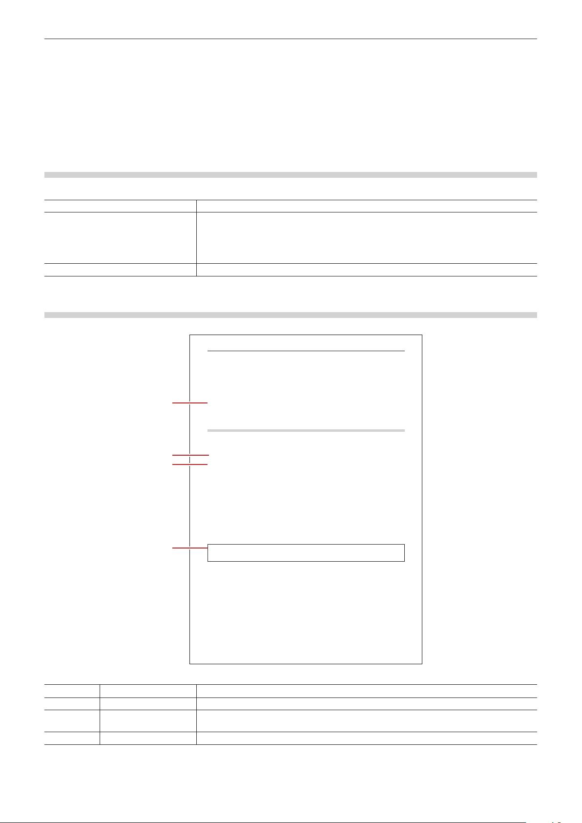
How to Read Reference Manual
Start up EDIUS and click [Help] → [Help] to display the Reference Manual.
The following image illustrates the conventions and their meanings in this manual:
Chapter 6 Editing Timelines — Video Layout
Video Layout
Transforming/Rotating Video
(1)
(2)
(3)
(4)
2
f
“Layout Settings” (w page 360)
f
Editing Layouts
1)
Select a clip containing a video part, and double-click [Layouter] in the [Information] palette.
f “Showing/Hiding [Information] Palette” (w page 332)
f
“[Layouter] Dialog Box” (w page 241)
1 Alternative
f
f
f [F7]
2
f
f
f
f
2)
Edit the layout.
f “[Crop] tab” (w page 242)
f “[Transform] tab” (w page 242)
f “[Parameter] tab” (w page 242)
3 Note
f
3)
Click [OK].
f
2
f
“Registering Effects to [Effect] Palette” (w page 338)
* The illustration is a sample image. This image may differ from the actual page in this manual.
(1)
2
Explains useful points to operate functions.
(2) Reference page Indicates the related pages.
(3)
1 Alternative
Explains the alternative procedure to operate the same function of the ow in a different
process.
(4)
3 Note
Explains the points to be aware of or restricted to operate functions.
23
Page 24

Chapter 1 Summary — About Manuals
New Functions and Changed Functions
See our website for new functions and changed functions from the previous version of EDIUS, and functional differences by product.
“Our Website” (w page 24)
This manual is base on EDIUS Elite. Please note that EDIUS Pro is not equipped with the following major functions.
f Audio bitstream pass-through (Dolby-E/AC3)
f K2 Clip import /export
f Simul edit capture
f Interaction with GV STR ATUS
f DNxHD codec supported
f Dolby Digital Professional/Dolby Digital Plus supported
* It can be supported on EDIUS Pro by using the optional license. (EDIUS 7.4 or later)
*
*
Our Website
The latest information of our products including this product are released on the Grass Valley website. Visit our website to download the
latest drivers, utilities, applications, product manuals (online or PDF) or to see FAQs, for your better editing environment.
Online Manual
On our website, we provide the online manual in the HTML version of the Reference Manual of this product. You can use it for keyword
searching.
3 Note
f The contents of the online manual are subject to change without notice due to updated information or changes of the product
specications. Therefore, the contents of the online manual may dif fer from that of the Reference Manual which came with the product
you purchased. Visit our website for the latest information and the online manual.
f The contents in the Reference Manual are at the time when the rst product is released. Therefore, the contents in the manual may
include different specications and functions from those of the product you purchased, because of the later minor changes.
f Note that we are not liable for any damages (including damages by data corruption, business interruption, sales information loss, etc.)
caused by using or being not able to use the online manual, even if there were prior notications of the damage occurrences and the
possible claims of compensation for the damages by a third party.
24
Page 25

Chapter 1 Summary — Grass Valley HQ Codec/Grass Valley HQX Codec
Grass Valley HQ Codec/Grass Valley HQX Codec
With EDIUS, you can edit 4K and high-denition video in individual frame units. Optimal codec for editing high-resolution video is Grass
Valley HQ Codec/Grass Valley HQX Codec. By using the Grass Valley HQ Codec/Grass Valley HQ X Codec, the editing response time can
be dramatically improved. When you use the Grass Valley HQ Codec, approximate le size will be 7 times larger than the HDV (it may vary
depending on the video or settings), therefore, it is recommended to use a hard disk drive that is as fast and large as possible.
Grass Valley HQ X Codec supports 4K and 10-bit video quantization bitrate.
25
Page 26
Chapter 1 Summary — Starting up EDIUS
Starting up EDIUS
Start-up and Exit
This section explains how to start up EDIUS, how to operate it at initial start-up, and how to exit the application.
How to Start up
The following explains how to start up EDIUS.
1)
Double-click the EDIUS icon on the desktop.
f The [Star t Project] dialog box appears.
“[Start Project] Dialog Box” (w page 26)
1 Alternative
f For Windows 7, click [Start] to display the star t menu, and click [All Programs] → [Grass Valley] → [EDIUS].
f For Windows 8, display the start screen, right-click on a location where there is no tile, click [All apps] to display all the programs installed,
and then click [Grass Valley] → [EDIUS].
f For Windows 8.1, click the down arrow at the lower left of the start screen to display all applications, and click [EDIUS].
2
f A dialog box to notify the latest updater may appear at the startup of EDIUS.
“[Update Notication] Dialog Box” (w p age 81)
[Start Project] Dialog Box
Prole list Manage each prole of the window layouts, system settings, user settings, etc, and use them
by switching each.
“Editing Environment Management” (w page 104)
[New Project] When you start EDIUS for the rst time, click this button to start up the [Create Project Presets]
wizard. Af ter you create a new project preset, a new project le can be created.
“Creating New Project Presets at Initial Start-up” (w page 43)
When existing project presets are registered, click this button to display the [Project Settings]
(Simple Settings) dialog box and create a new project le.
“Creating New Project at Start-up” (w page 43)
[Open Project] Click this button to display the [Open] dialog box to open an existing project le.
[Recent Project] Displays the recently worked project les from the latest one. Double-click the le to open the
project le.
Every click switches the sorting order to be ascending or descending. Right-click the item
name and click the items you want to display or hide.
To delete the project history, select and right-click the le and click [Clear history] or [Clear All
History].
No project name is displayed if no project le is saved.
[Open] Open the project le.
[Close] Exit EDIUS.
At Initial Start-up
When you start up EDIUS for the rst time after installation, specify a folder where the project les you use for editing are saved.
1)
Start up EDIUS.
f The serial number entry screen appears.
2)
Enter the serial number, and click [Register].
f When using a PC in the online environment, the serial number is registered.
For how to register the serial number on a PC in the ofine environment, see the Installation Guide.
3)
A message appears, and click [OK].
f The [Folder Settings] dialog box appears.
26
Page 27

Chapter 1 Summary — Starting up EDIUS
4)
Click [Browse] to specify the folder where the project files are saved.
5)
Click [OK].
2
f You can change the save destination of the project folder by using [Application] in [User Settings] → [Project le].
“[Project le]” (w page 96)
Exiting Project
Close the project le you edited, and return to the [Start Project] dialog box.
1)
Click [File] on the menu bar, and click [Exit Project].
2)
Click [Yes].
f Click [No] if you do not want to save the project. Click [Cancel] to cancel the operation.
Exiting EDIUS
The following explains how to exit EDIUS.
1)
Click [File] on the menu bar, and click [Exit].
2)
Click [Yes].
f Click [No] if you do not want to save the project. Click [Cancel] to cancel the operation.
1 Alternative
f Click [×] in the preview window.
f Exiting EDIUS: [Alt] + [F4]
27
Page 28

Chapter 1 Summary — EDIUS Conguration
EDIUS Conguration
Edit Workow and Various Settings
This section explains the workows to edit videos with EDIUS and their relation to various settings. For the general overview and
relationship diagram, see the list of the setting descriptions.
“List of Setting Descriptions” (w page 30)
If you use a regular user prole, the settings for the editing environment can be changed anytime.
2
f In EDIUS, both the administrator who congures the environment and the operator who performs the editing tasks in mind, a new
restricted user prole with a limited access is introduced to prevent system settings. If access restriction is not required, use the regular
user prole.
Editing Environment Conguration (Restricted users cannot perform this task)
Create New Project Presets → Start up Dialog Box or System Settings
Create and register a project preset.
“Creating New Project Presets at Initial Start-up” (w page 43)
“Creating New Project Presets” (w page 51)
* A restricted user can change and use the content of the preset, but cannot create a new preset. Before you star t editing using the restricted user
prole, ensure to create a preset.
Create New Device Presets → System Settings
To use cameras, decks, or Grass Valley hardware products to import sources or export projects, create and register device presets. A
device preset is required for each device as well as for each format and le type to import and export.
“Registering External Devices that Interact with Device Presets” (w page 109)
* A restricted user cannot create or change a device preset. Before you start editing using the restricted user prole, ensure to create a preset with
the device, stream type and format,
Other Editing Environment Settings → System Settings
f Congure connection settings and detailed settings to use a preview monitor and/or input controllers including a fader.
f Register the plug-in effects.
f Congure other processes including the capture and rendering.
“[System Settings]” (w page 77)
Create New Prole → System Settings
If you want to change the editing environments for dif ferent projects or use the restricted user prole to perform editing tasks, you can
register the device preset described above and other editing environment settings as a prole.
If you use the restricted user prole, you need a restricted user prole for each PC used by a restricted user.
The proles can be managed through network.
“Editing Environment Management” (w page 104)
Creating a New Project
Create a New Project → Project Settings
Select a project preset and open a project. The preset content can be changed in the project settings.
“Creating New Project at Start-up” (w page 43)
“Creating Project with Different Settings from Project Preset” (w page 44)
28
Page 29

Chapter 1 Summary — EDIUS Conguration
Importing Sources
Capturing Sources from Cameras or Decks
Select a device preset and capture sources. A device preset must be created in the system settings before capturing.
“Capturing and Importing” (w page 14 0)
Copying File-Based Sources
Use the source browser to copy source les from CD, DVD, BD, and other devices including AVCHD cameras, P2, and XDCAM* easily.
Files can be browsed by simply connecting a device or drive to your PC and inserting the storage media.
“Importing Files from Source Browser” (w page 153)
* You can register the target in the system settings if you want to browse les previously copied to the hard disks.
“[Importer/Exporter]” (w pag e 81)
Editing Timelines
Congure TC Presets and Channel Maps → Sequence Settings or Project Settings
Congure TC presets and channel maps for each sequence. The default value for a new sequence can be changed in the project settings.
“Sequence Settings” (w page 51)
“Changing Project Settings” (w page 50)
Customize Editing Environment → User Settings
Customize various settings including the folder to save the project les, timeline settings, information displayed in preview, as well as
buttons and windows. Keyboard shor tcut and input controller settings can be imported and exported. These settings are recorded in the
user prole in use, and changed settings are reected instantly.
“[User Settings]” (w page 94)
“Screen Customization” (w pa ge 121)
“Registering Proles” (w page 104)
Editing Video Layouts
Edit the video layout using the layouter. The edited content can be saved as a preset in the layouter or registered as a user preset ef fect to
the effect palette to export.
“Video Layout” (w pag e 2 41)
“User Preset Effects” (w page 339)
Editing Effects
Edit existing ef fects and register and export as a user preset effect to the effect palette.
“User Preset Effects” (w page 339)
Export
Export to File → Exporter
Select an exporter and export to different le types. The exporter settings can be registered and exported as a preset.
“Exporting in File Formats” (w page 390)
“Creating Preset Exporters” (w pag e 414)
Export to Devices
A device preset must be congured to use Grass Valley hardware products or export to other DV devices.
“Registering External Devices that Interact with Device Presets” (w page 109)
29
Page 30
Chapter 1 Summary — EDIUS Conguration
List of Setting Descriptions
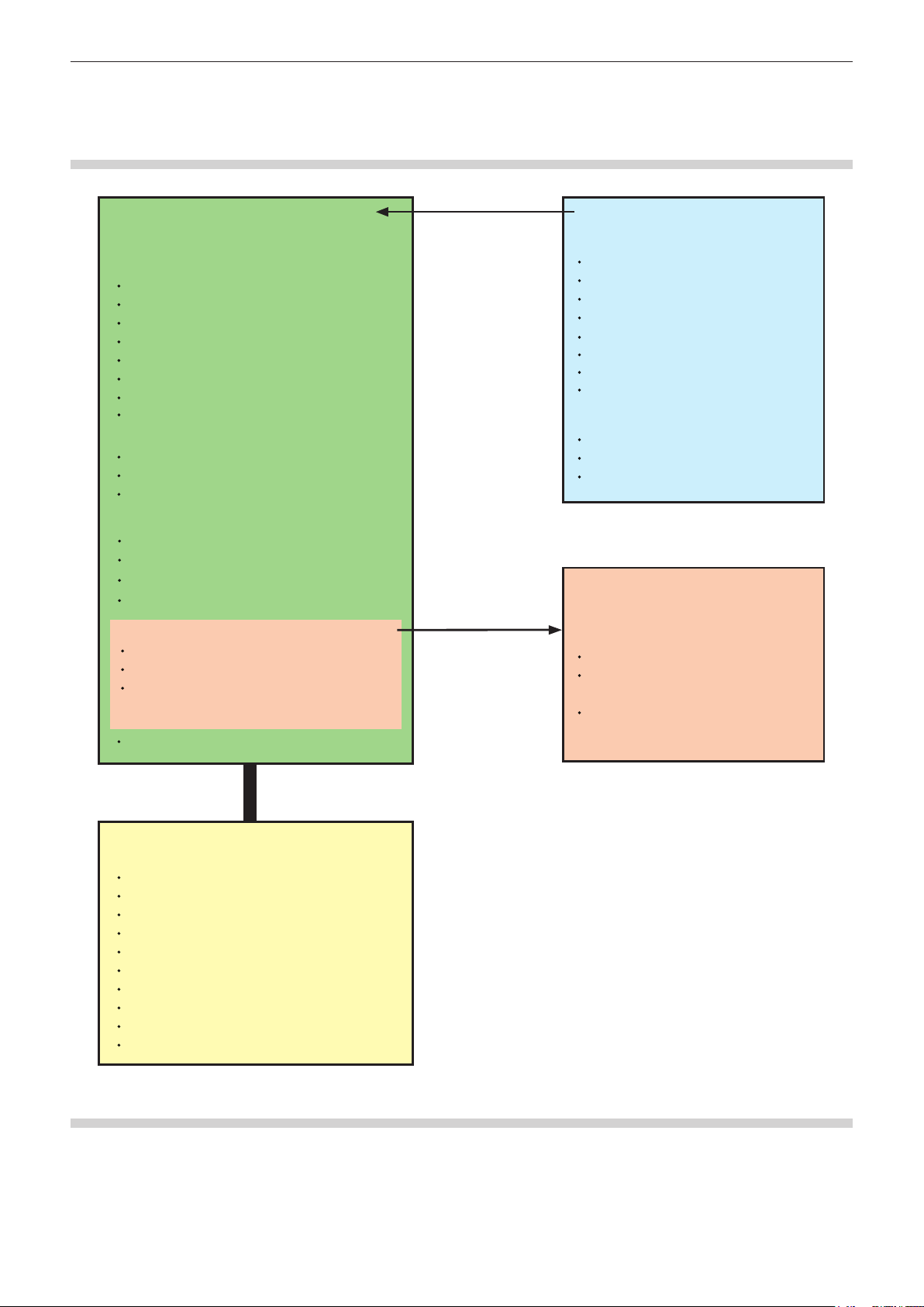
Relationship between Project Settings/Sequence Settings/Device Preset
The following diagram illustrates the settings available in each setting and their descriptions:
3URMHFWVHWWLQJV
6HWWLQJVSHUSURMHFW
9LGHRIRUPDWV
>)UDPH6L]H@
>$VSHFW5DWLR@
>)UDPH5DWH@
>)LHOGRUGHU@
>9LGHR&KDQQHO@
>9LGHR4XDQWL]DWLRQ%LW5DWH@
>3XOOGRZQ7\SH@
>6WHUHRVFRSLF(GLWLQJ@
$XGLRIRUPDWV
>6DPSOLQJ5DWH@
>$XGLRFKDQQHO@
>$XGLR4XDQWL]DWLRQ%LW5DWH@
>6HWXS@
>5HQGHUIRUPDW@
>2YHUVFDQ6L]H@
>5HIHUHQFH/HYHO@
>5HVDPSOLQJPHWKRG@
>6HTXHQFHVHWXS'HIDXOW@
>7&SUHVHW@
>7&0RGH@'URSIUDPH1RQGURSIUDPH
>7RWDO/HQJWK@
>&KDQQHOPDS@
1XPEHURIWUDFNV
5HIOHFWSUHVHW
VHWWLQJV
'HIDXOWYDOXHZKHQ
FUHDWLQJVHTXHQFHV
3URMHFWSUHVHWV
9LGHRIRUPDWV
>)UDPH6L]H@
>$VSHFW5DWLR@
>)UDPH5DWH@
>)LHOGRUGHU@
>9LGHR&KDQQHO@
>9LGHR4XDQWL]DWLRQ%LW5DWH@
>3XOOGRZQ7\SH@
>6WHUHRVFRSLF(GLWLQJ@
$XGLRIRUPDWV
>6DPSOLQJ5DWH@
>&KDQQHO@
>$XGLR4XDQWL]DWLRQ%LW5DWH@
6HTXHQFHVHWWLQJV
6HWWLQJVSHUVHTXHQFH
>6HTXHQFHVHWWLQJV@
>7&SUHVHW@
>7&0RGH@'URSIUDPH1RQGURS
IUDPH
>7RWDO/HQJWK@
>&KDQQHOPDS@
:KHQH[SRUWLQJWRGHYLFHVWKHSURMHFWVHWWLQJVDQGGHYLFHSUHVHWV
PXVWEHPDWFKHG
'HYLFHSUHVHWV
6HWWLQJVSHUGHYLFH
,QWHUIDFH,QSXW2XWSXW
6WUHDPW\SH,QSXW2XWSXW
9LGHRIRUPDW,QSXW2XWSXW
&RGHF
)LOHIRUPDW
3UR[\FUHDWLRQ
$XGLRIRUPDW,QSXW2XWSXW
$XGLRLQWHUIDFH,QSXW2XWSXW
6WHUHRVFRSLF
6HSDUDWHH[SRUWRIVWHUHRVFRSLF/5
System Settings
In the system settings, you can change the settings for project presets, prole management, import/export hardware, conguration for
source capture.
If you use the restricted user prole, the system settings cannot be changed.
The major setting items are as follows:
30
Page 31

Chapter 1 Summary — EDIUS Conguration
r Application settings
Buffer settings
Capture settings
Rendering settings
Prole management
Project preset management
Loudness meter settings
Transfer destination settings for the source browser
SNFS bandwidth restriction settings
File export settings
Update notication settings
r Hardware settings
Preview device settings
Device preset management
r Importer/Exporter settings
Settings for each importer and exporter
r Effect plug-in settings
Plug-in registration
r Input controller settings
Connection settings (Key settings for each controller are available in the user settings.)
User Settings
Change how clips are handled on the timeline, or change the user editing environment, for example, by customizing screens or buttons.
Both restricted users and administrator users can change and save settings in proles from any user prole, and record them to the proles.
The major setting items are as follows:
r Application settings
Project le settings (including save destination)
Match frame settings
Background job settings
Timeline settings
Proxy Mode Settings
Other settings
r Preview settings
Playback settings (including preroll)
Monitor settings
On-screen display settings
Information display settings (including zebra preview and safe area display)
Preroll editing settings
r User interface settings
Button
Control
Keyboard shortcuts
Bin
Window color
r Source settings
Duration
Automatic correction
Restore ofine clip
Partial transfer
K2 assets registration
31
Page 32

Chapter 1 Summary — EDIUS Conguration
r Input controller
Key settings for each controller
2
f Keyboard shortcut and input controller key settings can be imported and exported to use in other EDIUS installations on other PCs.
f Prole can be imported and exported to use in other EDIUS installations on other PCs. The proles can also be managed through
network.
32
Page 33

Chapter 1 Summary — Screen Conguration
Screen Conguration
EDIUS Screen Conguration
This section explains the overall EDIUS screen conguration as well as each window and palette.
Whole Screen Conguration
Various windows are displayed when using EDIUS, and basically you use 7 windows for editing video. You can easily edit video in dual
monitor, as each window can be placed without overlapping with each other.
Each window can be resized by dragging its side line or the corner edge. As the windows snap to each other, you can place windows
aligned by side line or corner edge. The window layout can also be saved.
When Displaying in Dual Monitor
When Displaying in Single Monitor
2
f When multiple windows are placed in alignment, all the snapped windows can be resized at one time by resizing one of them. Resize
operation with [Shift] on the keyboard held down resizes only the selected window. However, this function may be unable depending on
the setting of Windows.
Preview Window
The following explains about 2 types of the preview windows, Player and Recorder.
“Switching Between Single Mode/Dual Mode” (w page 128)
33
Page 34

Chapter 1 Summary — Screen Conguration
r Dual mode
Player appears on the left, and Recorder on the right in the dual mode.
r Single mode
In the single mode, switch the display window by clicking [Change to Player]/[Change to Recorder].
2
f Click the GV icon in the preview window to minimize the window.
Menu Bar
You can execute most of the operations from the menu bar. Click and select an item.
2
f Click [Help] on the menu bar, and click [User Registration] to perform user registration after installation.
f Click [Help] on the menu bar, and click [Serial number registration] to register the serial number. After registering the serial number,
restart EDIUS to enable the functions.
f Perform the following procedure to refer to Help for how to use the application:
g Click [Help] on the menu bar, and click [Help].
g Help: [F1]
f Click [Help] on the menu bar, and click [Version Info] to refer to the version information.
34
Page 35

Chapter 1 Summary — Screen Conguration
Player
This window is used to playback the source clips and to capture the source from external devices.
(1) (3) (2) (3)
(1) Timecode area Display the playback position, In point, Out point, duration and the total length of the source
data.
If the setting is dened incorrectly, such as the setting that Out point is set before In point, the
timecode turns red.
The value can be changed by clicking the timecode.
Copy and paste are also available by right-clicking the timecode.
(2) Buttons for playing a
source
(3) Buttons for editing a
source
Used for playing clips and controlling external devices (play, fast forward, stop, etc.).
“Playback with Player Operation Buttons” (w page 169)
Used for setting In and Out points, adding a clip to the timeline, capturing, or creating a subclip.
35
Page 36

Chapter 1 Summary — Screen Conguration
(1) (2) (3)
Recorder
This window is used to play the timeline or edit a clip.
(1) (3) (2) (3)
(1) Timecode area Display the playback position, In point, Out point, duration and the total length of the source
data.
If the setting is dened incorrectly, such as the setting that Out point is set before In point, the
timecode turns red.
The value can be changed by clicking the timecode.
Copy and paste are also available by right-clicking the timecode.
(2) Buttons for playing the
timeline
(3) Buttons for editing the
timeline
Used for controlling clips placed on the timeline (playback, fast forward, stop, etc.).
“Playing Back with Recorder Operation Buttons” (w page 272)
Used for setting In and Out points, jumping to the edit point (the border of clips), or exporting to
le or tape.
Timeline Window
This window is used to place the clips on the track or apply effects.
Clips are placed from left to right of the timeline in time series.
(4)
(5)
(6)
(9)
(
10
11
(
(12)
)
)
(7)
(8)
(1) Mode bar These buttons are used to switch the editing modes. The button types and sort order can be
customized.
“Switching the Editing Mode” (w page 210)
“Operation Button Settings” (w p age 121)
36
Page 37

Chapter 1 Summary — Screen Conguration
(1) (2) (3) (4)
(2) Sequence tab Tab for using clips on the timeline as a set
(3) Operation buttons These buttons are used for editing operations. The button types and sort order can be
customized.
“Operation Button Settings” (w p age 121)
(4) Time scale Indicate the scale for the time on the timeline.
(5) Time scale settings Change the display unit for time scale.
“Time Scale Settings” (w page 207)
(6) Track header Congure various settings including muting and locking each track, mapping channels,
synchronizing channels. It can be used to add and delete tracks.
“Track Header” (w page 202)
(7) Timeline Place clips in this area. It can also be used to add and delete tracks.
“Placing Clips” (w page 215)
“Operating Tracks” (w page 204)
(8) Status bar Display the number of imported les when a project is opened/number of all les, the number
of ofine clips, clip playback status, editing mode, and background job status, etc. Move the
cursor over the mode bar or timeline operation buttons to display the button names on lower
left.
(9) Timeline cursor Indicate the playback position or edit position of the timeline.
(10) Video part Indicate the presence of video in the clip.
(11) Audio part Indicate the presence of audio in the clip. Expand it to display a rubber band to adjust the
volume or pan.
“Adjusting the Volume and Pan of a Clip” (w page 373)
(12) Mixer area Congure keying and other settings.
Bin Window
This window is used to manage clips imported with EDIUS.
You can switch the show/hide setting for the folder view. You can switch the display method such as thumbnail, detailed information, and
other information for the clip view.
Management, display of the list, and search for captured clip are available.
Clip information (such as aspect ratio, frame rate, poster frame) can be checked or modied.
“Managing Clips” (w page 193)
(1) Folder view Display folders in tree structure.
“Operations in the Folder View” (w page 196)
(2) Operation buttons Perform various operations.
(3) Clip view Display clips in the folder as a list.
“Operations in the Clip View” (w page 193)
(4) Metadata view Display the clip metadata in a list.
37
(5)
Page 38

Chapter 1 Summary — Screen Conguration
(1) (2) (3) (4)
(5) Simple search bar Press [F3] on the keyboard to display this bar. Clips in this folder can be searched.
2
f The upper and lower parts of the bin window are extended, by every double-click on a position of the title bar (without any button) in the
bin window.
Source Browser Window
This window is used to check source les in external devices such as CD/DVD and AVCHD cameras to which le-based video or audio is
recorded.
You can switch the show/hide setting for the folder view. You can switch the display method such as thumbnail, detailed information, and
other information for the clip view.
Display of the list, transfer to the bin, and search for the sources in external devices are available.
(1) Folder view Display devices and drives connected to the PC in a tree. When the media is inserted into the
device or drive, the media name is displayed in the tree. Click the media name to display the
stored les in the clip view. To browse the local disk, you can register the folder to display in the
(2) Operation buttons Perform various operations. The button types and operations differ from device to device.
(3) Clip view Displays a list of source les in the external devices.
(4) Metadata view Display a list of source le metadata.
(5) Simple search bar Press [F3] on the keyboard to display this bar. Search source les in the external devices.
folder view through System Settings in advance.
“[Importer/Exporter]” (w pag e 81)
“Importing Files from Source Browser” (w page 153)
2
f The upper and lower parts of the source browser window are extended, by every double-click on a position of the title bar (without any
button) in the source browser window.
Palette
There are 3 types of palettes: Information palette, Effect palette, and Marker palette.
(5)
38
Page 39

Chapter 1 Summary — Screen Conguration
[Information] Palette
“Showing/Hiding [Information] Palette” (w page 333)
f Display the information of the clip placed on the timeline.
f Display information on the set effects and set whether to apply effects or the order.
f Adjust the set ef fects.
f Congure the video layout if a clip has a video part.
[Effect] Palette
“Showing/Hiding [Effect] Palette” (w page 302)
f Video or audio effects to add to clips are registered.
f Register or delete customized effect.
[Marker] Palette
Manage the sequence markers appended to the timeline and clip markers appended to a clip. The [Sequence Marker] and [Clip Marker] lists
can be switched by clicking the button.
39
Page 40

Chapter 1 Summary — Screen Conguration
r [Sequence Marker] List
“Displaying the [Sequence Marker] List” (w page 266)
f Set and delete a sequence marker.
f Jump to a desired sequence marker or add comments.
f Import or export a sequence marker list.
r [Clip Marker] List
“Displaying the [Clip Marker] List” (w page 260)
f Set and delete a clip marker.
f Jump to a desired clip marker or add comments.
f Import or export a clip marker list.
2
f Follow the step below to show/hide 3 palettes together.
g Click [View] on the menu bar, and click [Palette] → [Show All] ([Hide All]).
g Displaying all: [H]
f You can combine 3 palettes into 1 palette. All palettes can be combined to the bin window or the source browser window.
“Combining Bin Window/Source Browser Window with a Palette” (w p age 119)
f Every double-click on the title bar of a palette expands and contracts the palette ver tically.
40
Page 41

Chapter 1 Summary — Entry of Values
Entry of Values
Entering Values Using Keyboard and Mouse
This section explains the setting operation for the values in each settings dialog box.
Direct Input of Value
You can directly enter values with [0] to [9] on the keyboard.
1)
Select the input field and enter the value on the keyboard.
f You can enter the value in the HHMMSSFF format (H = hour; M = minute; S = second; and F = frame). For example, enter “43S21F” or
“4321” in only numerics for 43 seconds and 21 frames. Enter “10M” or “100000” for 10 minutes. If entering “3H2M1S0F”, the value will be
“03:02:01:00”.
2)
Press [Enter] on the keyboard.
Offset Input
You can enter variation values in the input eld.
1)
Select the input field and enter the variation value from the current set value.
2)
Press [Enter] on the keyboard.
f Enter “-” before the value to decrease the set value.
f Enter “+” before the value to increase the set value.
2
f Offset input is only available for entering the timecode.
Setting with Arrow Keys
You can enter values with keys on the keyboard.
1)
Select the input field and change the value with arrow keys on the keyboard (↑, ↓, ←, →).
2)
Press [Enter] on the keyboard.
Entering with Mouse Wheel
The set values can be changed with the mouse wheel. The mouse wheel is in the center of the mouse.
1)
Move the mouse cursor near the input field.
f The shape of the mouse cursor changes.
2)
Click the value and rotate the mouse wheel.
1 Alternative
f Hold the right button of the mouse in the settings input eld, and drag the mouse upward to increase the value. The value continues to
increase while the mouse is dragged. The value increases accordingly, when the mouse is moved away from the initial drag position.
f In the same way, hold the right button of the mouse and drag downward to decrease the value.
f Hold the left button of the mouse and drag upward to increase the value by the movement of the mouse. In the same way, drag downward
to reduce the value. In this case, the value does not change unless you move the mouse.
41
Page 42

Chapter 2
Project Settings
When working with EDIUS, the largest work unit is the project le. A project le contains various information including edit histories and
video formats.
This chapter explains the operations and settings of the project.
42
Page 43

Chapter 2 Project Settings — Project Operations
Project Operations
Creating New Project
This section explains how to create a new project when or after EDIUS starts.
To create a project, set a project format according to the format for the export destination, and register it as a project preset.
Project presets are registered in advance, depending on the application. If this happens, select a project preset according to the format for
the export destination.
Creating New Project Presets at Initial Start-up
When you start up EDIUS for the rst time after installation, congure the format of the project to create, and register it as a preset.
1)
Click [New Project] in the [Start Project] dialog box.
f The [Create Project Presets] wizard will start up.
2)
Check more than one item for [Size], [Frame Rate], [Bit] (in this order), and click [Next].
f Congure the video size and frame rate, and video quantization for the project format to create with EDIUS. Multiple check boxes can be
selected for each item.
2
f Set a video quantization bitrate to 10 bits to edit with 10 bit precision retained. However, it may turn out to be the 8 bit precision depending
on the effects you use. The formats that can be imported with 10 bit precision are Grass Valley, HQX AVI, uncompressed AVI, AVC-Intra,
QuickTime, Grass Valley HQX MOV, and XAVC. The formats that can be exported with 10 bit precision are Grass Valley HQX AVI, AVCIntra and uncompressed (v210) AVI.
3)
Check the content.
f A list of formats corresponding to the setting congured in step 2) is displayed.
A preset of the checked formats will be created. Uncheck the formats you do not use.
2
f You can click [Back] to redo the settings.
4)
Click [Completed].
f The [Project Settings] (Simple Settings) dialog box appears, showing the created project preset as an icon in [Presets List].
“[Project Settings] (Simple Settings) Dialog Box” (w page 44)
3 Note
f To change the project preset you created, per form through [Application] in [System Settings] → [Project Preset]. You can create
additional project presets in the system settings. Note that changes will not be reected to presets if you check [Customize] in the
screen shown in step 4) and change the settings.
“[Project Preset]” (w page 79)
Creating New Project at Start-up
When EDIUS starts up, select a project preset and create a new project.
1)
Click [New Project] in the [Start Project] dialog box.
f The [Project Settings] (Simple Settings) dialog box appears.
“[Project Settings] (Simple Settings) Dialog Box” (w page 44)
2
f The [Create Project Presets] wizard will start up.
“Creating New Project Presets at Initial Start-up” (w page 43)
2)
Enter a project name in [Project name] of [Project file].
43
Page 44

Chapter 2 Project Settings — Project Operations
3)
Select a project preset, and click [OK].
2
f Click [Cancel] to return to the [Start Project] dialog box.
[Project Settings] (Simple Settings) Dialog Box
[Project le] [Project name]
Click the input eld to enter a project name.
[Folder]
Set the destination to save projects. To change the destination, click [...] and select a folder.
Check [Create folder with project name] to create a folder with the project name in the
destination folder.
[Presets List] Display registered project presets in a list. Double-click the icon to open a new project le with
the selected project preset setting.
[Customize] Check this item to change the detailed project preset settings (rendering format, and the
number of tracks and so on) and create a new project le. The settings of the existing project
preset will not be changed.
“Creating Project with Different Settings from Project Preset” (w page 44)
If you use the restricted user prole, the detailed settings of a project preset cannot be
changed.
[Description] Display the settings of the project preset selected in [Presets List].
Creating Project with Different Settings from Project Preset
When star ting up EDIUS, you can create projects with different settings from that set in detail as a project preset (rendering formats, track
numbers, etc.)
3 Note
f This section describes how to customize project preset settings to create a project. This procedure does not change the original
project preset. To create project presets or change project presets, per form through [Application] in [System Settings] → [Project
Preset].
“[Project Preset]” (w page 79)
1)
Enter a project file name in [Project name] of [Project file] in the [Project Settings] (Simple Settings)
dialog box.
f “[Project Settings] (Simple Settings) Dialog Box” (w page 44)
2)
Select a project preset.
3)
Check [Customize], and click [OK].
f The [Project Settings] (Detailed Settings) dialog box appears.
“[Project Settings] (Detailed Settings) Dialog Box” (w page 4 4)
4)
Configure a project, and click [OK].
[Project Settings] (Detailed Settings) Dialog Box
[Video Preset] Display a list of commonly used video formats. From this list, select a video format that suits
the export environment.
[Audio Preset] Display a list of commonly used audio formats. From this list, select an audio format that suits
the export environment.
(Expand button)
Click this button for detailed settings.
44
Page 45

Chapter 2 Project Settings — Project Operations
[Advanced] Click the expand button to customize detailed settings based on the format selected in [Video
Preset] and [Audio Preset]. You cannot change the items displayed in gray.
[Frame Size]
Select a frame size from the list.
Select [Custom] to enter a setting value in pixel. (The width must be a multiple number of 4.
The maximum value is 4096x2160 pixel.)
[Aspect Ratio]
Select an aspect ratio from the list.
[Frame Rate]
Select a frame rate from the list.
[Field Order]
For interlace, a eld order can be selected.
[Video Channel]
Select the channel to be exported (color channel/alpha channel) from the list. Select [YCbCr]
to export only color channel. Select [YCbCr + Alpha] to export both color channel and alpha
channel.
[Video Quantization Bit Rate]
Select a video quantization bitrate from the list.
[Pulldown Type]
This setting is only available for a frame rate of 24p or 23.98p. Select a convert format to
convert a 23.98p video to a 59.94i or 59.94p video signal. [Pulldown(2-3-2-3)] enables a
smooth playback, but is not appropriate for re-editing. Select this item for the nal export.
[Advanced pulldown(2-3 -3-2)] does not provide a smooth playback. Select this item to create a
temporar y le to edit.
[Stereoscopic Editing]
For 3D editing, select [Enable]. The stereoscopic edit mode is set.
“Stereoscopic Edit Workow” (w page 298)
[Sampling Rate]
Select an audio sampling rate from the list.
[Audio channel]
Select the number of audio channels from the list.
[Audio Quantization Bit Rate]
Select an audio quantization bitrate from the list.
[Setup] [Render format]
Select the default codec to be used for rendering and le export during editing. RGB, UY VY,
YUY2, RGBA and v210 are uncompressed AVI.
For some codec, the rendering quality can be congured by clicking [Detail].
“Detailed Settings for Codec” (w page 46)
[Overscan Size]
Enter the ratio when you use overscan. The value range is between “0” and “20”. If you do not
use overscan, enter “0”.
[Audio reference level]
Set the audio reference level. If you switch the display of the [Audio Mixer] dialog box to a VU
meter, a scale with the specied audio reference level at “0” is displayed.
[Resampling method]
Select a resampling method when transforming video with the layouter.
“Video Layout” (w pag e 2 41)
[Sequence setup (Default)] Default settings for creating a sequence.
[TC preset]
Enter the star t timecode of the timeline.
[TC Mode]
When NTSC has been selected for the project setting, select either drop frame or non drop
frame timecode display.
[Total length]
Set the length of the timeline by entering a number when the nal total length is xed. When the
project exceeds this length, the color of the timeline section that is over the limit change.
[Track (Default)] Default settings of a number of tracks and a channel map for creating new projects or
sequence.
[V Tracks]/[VA Tracks]/[T Tracks]/[A Tracks]
Set the number of tracks in which you place clips.
You can add or delete any tracks after opening a project.
[Channel map]
In the [Audio Channel Map] dialog box, congure the audio output channel of each track.
“Conguring Audio Channel Map” (w page 48)
“Entr y of Values” (w page 41)
2
f Formats that can be exported with alpha channel retained when [Video Channel] is set to [YCbCr + Alpha] are Grass Valley HQ AVI,
Grass Valley HQ X AVI and uncompressed (RGBA) AVI.
45
Page 46

Chapter 2 Project Settings — Project Operations
3 Note
f If a correct rendering format is not selected for the project settings, the item in [Render format] is displayed in red and the setting
cannot be completed.
Detailed Settings for Codec
You can congure the rendering quality for each codec in the [Project Settings] (Detailed Settings) dialog box.
“[Project Settings] (Detailed Settings) Dialog Box” (w page 4 4)
Grass Valley HQ AVI/Grass Valley HQX AVI/HQ MXF/HQX MXF
For the details of the items, see the [Settings - Grass Valley HQ]/[Settings - Grass Valley HQX] dialog box of [Preset Wizard], by clicking
[Hardware] in [System Settings] → [Device Preset]. Click [Save as default] to save the current settings as defaults.
“[Settings - Grass Valley HQ]/[Settings - Grass Valley HQ X] Dialog Box” (w page 111)
MPEG2 Program Stream
r [Basic Settings] tab
[Segment Encode] Check this item to export a clip of a raw source without re-encoding. Output speed is fast.
[Size] Select an image quality.
[Quality/Speed] Select quality from the list. The higher the quality, the more time it takes to be encoded.
[Bit Rate] Select a bitrate type.
[CBR] sets a xed transfer rate, allocating a xed number of bits during the encoding process.
Select a bitrate from the [Average(bps)] list. You can also enter a value directly.
[VBR] sets a variable transfer rate, altering the number of assigned bits according to the
complexity of the movement or image quality. Compared with [CBR], the media volume can be
used more ef ciently, and this enables more consistent image quality overall. Select a bitrate
from the [Average(bps)] and [Maximum(bps)] lists. You can also enter a value directly.
r [Extended Settings] tab
[Field Order] For interlace, a eld order can be selected.
[Chroma Format] Select a YUV pixel format from the list.
[Prole & Level] Select a prole & level. If [Chroma Format] is [4:2:0] and [4:2:2], the prole will be set to Main
Prole and 422Prole, respectively. The level for SD image quality will be Main Level, and
the level for HD image quality will be High Level. The prole & level changes according to the
format selected in [Chroma Format].
[GOP Structure] For MPEG, a certain number of frames is considered as a group, and operations such as
compression/enlargement and cut editing are performed on a GOP basis. A GOP comprises
“I frame”, “P frame” and “B frame”. The I frame allows images to be reproduced independently,
the P frame is for recording and reproducing only the dif ferences with the preceding image,
and the B frame reproduces images from the differences in the preceding and following
images. Select I, P and B frame patterns of the GOP from the list. Normally, select [IBBP].
[I-Frame Only] is comprised of only I-pictures. Editing is made easier, but the amount of data
increases in size.
[Picture count] Set the number of frames included in a group.
[Closed GOP] Check this item to complete information within each GOP. Although the amount of data
increases, the video can be re-edited using software that supports GOP-based editing.
Normally, leave this item unchecked.
MPEG2 for GF I frame only (100 Mbps)/MPEG2 for GF Long GOP (50 Mbps)/MPEG2 for XDCAM HD422/
MPEG2 for XDCAM HD LP/MPEG2 for XDCAM HD SP/MPEG2 for XDCAM HD HQ
Items that can be congured are the same as [MPEG2 Program Stream].
“MPEG2 Program Stream” (w page 46)
MPEG2 MXF
[Segment Encode] Check this item to export a clip of a raw source without re-encoding. This increases the output
speed.
46
Page 47

Chapter 2 Project Settings — Project Operations
[Bit Rate] Select a bitrate type.
[CBR] sets a xed transfer rate, allocating a xed number of bits during the encoding process.
Select a bitrate from the [Average] list. You can also enter a value directly.
[VBR] sets a variable transfer rate, altering the number of assigned bits according to the
complexity of the movement or image quality. Compared with [CBR], the media volume can be
used more ef ciently, and this enables more consistent image quality overall. Select a bitrate
from the [Average] and [Max] lists. You can also enter a value directly.
[Quality/Speed] Select quality from the list. The higher the quality, the more time it takes to be encoded.
[Field Order] For interlace, a eld order can be selected.
[GOP Structure] For MPEG, a certain number of frames is considered as a group, and operations such as
compression/enlargement and cut editing are performed on a GOP basis. A GOP comprises “I
frame”, “P frame” and “B frame”; the I frame allows images to be reproduced independently, the
P frame is for recording and reproducing only the differences with the preceding image, and
the B frame reproduces images from the dif ferences in the preceding and following images.
Select I, P and B frame patterns of the GOP from the list. Normally, select [IBBP].
[I-Frame Only] is comprised of only I-pictures. Editing is made easier, but the amount of data
increases in size.
[Picture count] Set the number of frames included in a group.
[Closed GOP] Check this item to complete information within each GOP. Although the amount of data
increases, the video can be re-edited using software that supports GOP-based editing.
Normally, leave this item unchecked.
[Chroma Format] Select a YUV pixel format from the list.
[Prole & Level] Select a prole & level. If [Chroma Format] is [4:2:0] and [4:2:2], the prole will be set to Main
Prole and 422Prole, respectively. The level for SD image quality will be Main Level, and
the level for HD image quality will be High Level. The prole & level changes according to the
format selected in [Chroma Format].
JPEG2000 MXF
[Bit Rate] Select a bitrate from the list.
HDV
[Segment Encode] Check this item to export a clip of a raw source without re-encoding. Output speed is fast.
If the frame rate of the export format is 23.98p, segment encode is not available.
[Quality/Speed]
Select the quality of the part to be re-encoded from the list. The higher the quality, the more
time it takes to be encoded.
DV AVI
Check [Use MSDV codec] to export the content to an MSDV codec AVI.
Creating a New Project after Start-up
You can create a new project after starting up EDIUS.
1)
Click the [Create New Sequence] list button on the timeline.
2)
Click [New Project].
f If you create a new project during the editing operation, a conrmation dialog box appears to ask if you want to save the current project
le.
f The [Project Settings] (Simple Settings) dialog box appears.
“[Project Settings] (Simple Settings) Dialog Box” (w page 44)
1 Alternative
f Click [File] on the menu bar, and click [New] → [Project].
f Creating a new project after start-up: [Ctrl] + [N]
47
Page 48

Chapter 2 Project Settings — Project Operations
2
f When creating a new project, the clips in the bin are initialized (all deleted).
3)
Enter a project name in [Project name] of [Project file].
4)
Select a project preset, and click [OK].
2
f Check [Customize] to change the detailed project preset settings (rendering format and the number of tracks and so on) and create a new
project.
“[Project Settings] (Detailed Settings) Dialog Box” (w page 4 4)
Conguring Audio Output Channel Map
Select the nal output channel for the output from the track. The settings can be registered as an audio channel map preset.
Conguring Audio Channel Map
Select the nal output channel for the output from the track.
1)
Click [Channel map] in the [Project Settings] (Detailed Settings) dialog box.
f “[Project Settings] (Detailed Settings) Dialog Box” (w page 4 4)
f The [Audio Channel Map] dialog box appears.
“[Audio Channel Map] Dialog Box” (w page 48)
2)
Click the point where the track and the channel to output intersect to configure the audio channel
map.
f Every click switches between [Stereo], [Mono], and [No Output folder].
f For stereo output, use a combination of an odd number channel and an even number channel and set this option to [Stereo]. If you output
in monaural, select [Mono], and if you do not output anything, select [No Output folder]. If the setting is invalid, “-” is displayed.
[Audio Channel Map] Dialog Box
(3)
(1)
(2)
(4)
(5) (6)
(1) [Bit stream] Set the pass-through for audio.
(2) Tracks The number or type of track to be displayed differs depending on the [Track (Default)] settings
in the project settings.
(3) Output channels The number of channels to be displayed dif fers depending on the [Audio Preset] or [Audio
Channels] settings in the project settings.
(4) Audio channel map
settings
(5) [Change Display Style] Click this item to switch the display view of the [Audio Channel Map] dialog box.
(6) [Preset] Register the settings as a preset.
Select the output channel for the output from the track. Every click switches between [Stereo],
[Mono], and [No Output folder].
“Creating Audio Channel Map Preset” (w page 49)
48
Page 49

Chapter 2 Project Settings — Project Operations
2
f Use the track header to place an audio channel of the source clip to a desired track.
“Connecting/Disconnecting the Source Channel” (w page 215)
3 Note
f To export a project with 8ch audio to Dolby Digital (AC-3), you can select the format for 5.1 channel. When you select formats for
multiple channels to output as in the case mentioned, set the export destination of each track with the audio channel map in advance.
If the expor t destination is not specied, the sound is muted. To play the sound in 5.1 channel surround, the sound is required to be
created to be suitable for surround play. Note that the surround effect is not applied automatically only by setting the audio channel
map and selecting 5.1 channel for the export format.
Creating Audio Channel Map Preset
You can register frequently used audio channel map settings as presets.
1)
Configure the audio channel map in the [Audio Channel Map] dialog box.
f “[Audio Channel Map] Dialog Box” (w page 48)
2)
Click [Preset], and click [Save].
3)
Enter a preset name, and click [OK].
2
f You can overwrite an existing audio channel map preset with the current settings. In step 2), click [Preset], and click [Update] → [Preset
Name]. Conrm the preset name, and click [OK].
f To display a list of the audio channel map presets, click [Preset] in the [Audio Channel Map] dialog box, and click [Properties].
Switching Audio Channel Map Presets
Switch the audio channel map presets to use.
1)
Click [Preset] in the [Audio Channel Map] dialog box, and click [Load].
f “[Audio Channel Map] Dialog Box” (w page 48)
f A list of the audio channel map presets is displayed.
2)
Select a preset, and click [OK].
Deleting Audio Channel Map Preset
You can delete audio channel map presets you created.
1)
Click [Preset] in the [Audio Channel Map] dialog box, and click [Properties].
f “[Audio Channel Map] Dialog Box” (w page 48)
f A list of the audio channel map presets is displayed.
2)
Select a preset, and click [Delete].
3)
Click [Yes].
Importing Audio Channel Map Preset (Import)
Import an audio channel map preset.
1)
Click [Preset] in the [Audio Channel Map] dialog box, and click [Properties].
f “[Audio Channel Map] Dialog Box” (w page 48)
f A list of the audio channel map presets is displayed.
49
Page 50

Chapter 2 Project Settings — Project Operations
2)
Click [Import].
3)
Select a file, and click [Open].
Exporting Audio Channel Map Preset (Export)
Expor t an audio channel map preset you created.
1)
Click [Preset] in the [Audio Channel Map] dialog box, and click [Properties].
f “[Audio Channel Map] Dialog Box” (w page 48)
f A list of the audio channel map presets is displayed.
2)
Select a preset, and click [Export].
f The [Save As] dialog box appears.
3)
Set a file name and save destination, and click [Save].
Changing Project Settings
This section explains how to change the project settings during the editing operation.
Switching Project Settings
You can change project settings while editing by switching project presets.
2
f To create a new project preset or change the existing project preset settings, use [Application] in [System Settings] → [Project Preset].
“Creating New Project Presets” (w page 51)
1)
Click the [Save Project] list button on the timeline.
2)
Click [Project Settings].
1 Alternative
f Click [Settings] on the menu bar, and click [Project Settings].
3)
Select a project preset, and click [OK].
Changing Project Settings
Change the project settings by modifying the detailed settings of an existing project preset.
3 Note
f The settings of the original preset will not be changed if you change the project settings of a project you are currently editing.
To create a new project preset or change the existing project preset settings, use [Application] in [System Settings] → [Project Preset].
“Creating New Project Presets” (w page 51)
f When changing the settings for [ TC preset], [ TC Mode], [Total Length], and [Channel map] in the project settings while editing a
project, the change is not reected in the created sequence. Change the settings of the created sequence in the [Sequence settings]
dialog box for each sequence.
“Sequence Settings” (w page 51)
50
Page 51

Chapter 2 Project Settings — Project Operations
1)
Click the [Save Project] list button on the timeline.
2)
Click [Project Settings].
1 Alternative
f Click [Settings] on the menu bar, and click [Project Settings].
3)
Select a project preset, and click [Change current setting].
f The [Project Settings] (Detailed Settings) dialog box appears.
“[Project Settings] (Detailed Settings) Dialog Box” (w page 4 4)
4)
Change the settings, and click [OK].
Sequence Settings
You can change the settings of the sequence settings in the [Sequence settings] dialog box.
1)
Click the [Save Project] list button on the timeline.
2)
Click [Sequence settings].
f The [Sequence settings] dialog box appears.
“[Sequence settings] Dialog Box” (w pag e 51)
1 Alternative
f Click [Settings] on the menu bar, and click [Sequence settings].
f Right-click the sequence tab, and click [Sequence Settings].
f Right-click a sequence clip in the bin, and click [Sequence Settings].
3)
Change the settings, and click [OK].
[Sequence settings] Dialog Box
[Sequence name] Enter the name of the sequence.
[TC preset] Set the star t timecode of the timeline.
[TC Mode] When NTSC has been selected for the project setting, select either drop frame or non drop
frame timecode display.
[Total Length] Set the total length of the timeline of sequence by directly entering the value. When the timeline
exceeds this length, the color of the timeline section over the limit changes.
[Preserve Ancillary data] Check this item to set the sequence to hold ancillary data.
[Channel map] Set audio output channel for each track.
“Conguring Audio Channel Map” (w page 48)
“Entr y of Values” (w page 41)
Creating New Project Presets
Creating a Project Preset
1)
Click [Settings] on the menu bar, and click [System Settings].
51
Page 52

Chapter 2 Project Settings — Project Operations
2)
Click the [Application] tree, and click [Project Preset].
f The [Project Preset] screen appears.
“[Project Preset] Screen” (w page 52)
3)
Click [New Preset].
f The [Project Settings] dialog box (for creating new project presets) appears.
“[Project Settings] Dialog Box (for creating new project presets)” (w page 52)
3 Note
f Clicking the [Default Icon Folder] checkbox in the [Select Icon] dialog box does not uncheck the item while default icon folder is
displayed. The display returns to the default icon folder display by clicking [...] and checking the item while a different folder is
displayed.
4)
Set each item and click [OK].
f The newly created preset is displayed as an icon in [Presets List].
[Project Preset] Screen
[Presets List] Display registered project presets in a list. The list can be resorted by dragging the icons.
[Description] Display the settings of the project preset selected in [Presets List].
[Preset Wizard] Start up the [Create Project Presets] wizard so that new project presets can be easily created.
“Simple Creation of Project Presets” (w page 52)
[New Preset] Create new project presets.
[Copy] Duplicate the selected project preset.
[Modif y] Change the settings of the selected project preset. Click this item to display the [Project
Settings] dialog box (for creating new project presets).
“[Project Settings] Dialog Box (for creating new project presets)” (w page 52)
[Delete] Delete the selected project preset.
[Project Settings] Dialog Box (for creating new project presets)
[Name] Enter the name of the project preset.
[Select Icon] Displays the [Select Icon] dialog box to select the preset icons.
To use any image you like, click [...] in the [Select Icon] dialog box, and select a le.
[Preset] Click this item to call up existing project presets.
Setting items other than the above are the same as those for the project presets (Detailed Settings).
“[Project Settings] (Detailed Settings) Dialog Box” (w page 4 4)
Simple Creation of Project Presets
1)
Click [Settings] on the menu bar, and click [System Settings].
2)
Click the [Application] tree, and click [Project Preset].
3)
Click [Preset Wizard].
4)
Check more than one item for [Size], [Frame Rate], [Bit] (in this order), and click [Next].
f Congure the video size and frame rate, and video quantization for the project format to create with EDIUS. Multiple check boxes can be
selected for each item.
2
f Set a video quantization bitrate to 10 bits to edit with 10 bit precision retained. However, it may turn out to be the 8 bit precision depending
on the effects you use. The formats that can be imported with 10 bit precision are Grass Valley, HQX AVI, uncompressed AVI, AVC-Intra,
QuickTime, Grass Valley HQX MOV, and XAVC. The formats that can be exported with 10 bit precision are Grass Valley HQX AVI, AVCIntra and uncompressed (v210) AVI.
52
Page 53

Chapter 2 Project Settings — Project Operations
5)
Check the details.
f A list of formats corresponding to the setting congured in step 4) is displayed.
f A preset of the checked formats will be created, uncheck the formats you do not use.
2
f You can click [Back] to redo the settings.
6)
Click [Done].
f The newly created preset is displayed as an icon in [Presets List].
Deleting Project Presets
Delete the created project presets.
1)
Click [Settings] on the menu bar, and click [System Settings].
2)
Click the [Application] tree, and click [Project Preset].
3)
Select presets to be deleted in [Presets List], and click [Remove].
1 Alternative
f Right-click a preset in the project preset list, and click [Remove].
4)
Click [Yes].
3 Note
f Project presets registered by default cannot be deleted.
Duplicating Project Presets
1)
Click [Settings] on the menu bar, and click [System Settings].
2)
Click the [Application] tree, and click [Project Preset].
3)
Select presets to be deleted in [Presets List], and click [Copy].
1 Alternative
f Right-click a preset in [Presets List], and click [Copy].
Changing Project Presets
Change project preset settings.
1)
Click [Settings] on the menu bar, and click [System Settings].
2)
Click the [Application] tree, and click [Project Preset].
3)
Select presets to be deleted in [Presets List], and click [Change].
f The [Project Settings] dialog box (for creating new project presets) appears.
“[Project Settings] Dialog Box (for creating new project presets)” (w page 52)
1 Alternative
f Right-click a preset in [Presets List], and click [Change].
53
Page 54

Chapter 2 Project Settings — Project Operations
3 Note
f Project presets registered by default cannot be changed.
4)
Set each item and click [OK].
2
f Even when you change the project preset used in the project being edited, the settings of the project being edited are not changed. To
reect the changes, switch the setting to the project preset changed.
“Switching Project Settings” (w page 50)
Importing Project Presets (Import)
1)
Click [Settings] on the menu bar, and click [System Settings].
2)
Click the [Application] tree, and click [Project Preset].
3)
Right-click [Presets List], and click [Import].
4)
Select a project preset, and click [Open].
Exporting Project Presets (Export)
1)
Click [Settings] on the menu bar, and click [System Settings].
2)
Click the [Application] tree, and click [Project Preset].
3)
Select and right-click a preset in [Presets List], and click [Export] → [All] or [Selected preset].
4)
Specify a save destination, and click [Save].
Saving Project
A project le is saved as an ezp le. The le name of the project currently being edited is displayed in the timeline operation area.
The following explains how to save project les and about auto save/backup les.
3 Note
f After saving the project le, do not move or delete the source that is used for reference in the project. However, if the source is in the
folder where the project le is created, the folder as a whole can be moved.
Overwrite Saving
You can save the project with the project name entered when creating the project.
1)
Click [Save Project] on the timeline.
54
Page 55

Chapter 2 Project Settings — Project Operations
1 Alternative
f Click the [Save Project] list button, and click [Save Project].
f Click [File] on the menu bar, and click [Save Project].
f Overwrite saving a project: [Ctrl] + [S]
Saving in Another Name
You can save the current project le (the one being edited) with another name.
1)
Click the [Save Project] list button on the timeline.
2)
Click [Save As].
3)
In the [Save As] dialog box, specify a file name and save destination, and click [Save].
1 Alternative
f Click [Save Project] with [Shift] on the keyboard held down.
f Click [File] on the menu bar, and click [Save As].
f Saving a project in another name: [Shift] + [Ctrl] + [S]
Auto Save/Backup
If the auto save function is enabled, an auto save le is created at a specied interval.
A backup le is created when a project le is saved if the backup function is congured. This le is used as a backup when the project le is
corrupted or the system failed during the editing operation.
To congure auto save/backup, use [Application] in [User Settings] → [Project le].
“[Project le]” (w page 96)
By default, an auto save/backup le is automatically saved, with a “Project name-Year, Month, Day-Hour, Minute, Second .ezp” le name, in
the project folder where the corresponding project le is saved.
f Destination of an auto save le → “Project folder”/“Project”/“AutoSave”
f Destination of a backup le → “Project folder”/“Project”/“Backup”
3 Note
f Copy (transfer) the auto save/back up le to the folder where the project le is originally saved and import the le, to recover the
project from the auto save/back up le.
f Auto save/back up les are in the attributes of read-only and cannot be overwritten. Change the attributes of the le from Windows
Explorer in advance, or save as the different le.
“Opening Project File after Start- up” (w page 56)
“Saving in Another Name” (w page 55)
Importing/Exporting Project File Edited with EDIUS
This section explains how to impor t project les edited with EDIUS, how to consolidate a project, and how to export to an AAF or EDL le.
Opening Project File at Start-up
Select a project to import when EDIUS starts up.
1)
Double-click a project file from [Recent Project] in the [Start Project] dialog box.
f In [Recent Project], previously worked project les from the latest are displayed.
1 Alternative
f Click [Open Project], specify a le and click [Open].
f Select a project le from the [Recent Project] list, and click [Open].
2
f If you open a project le that is currently open for editing from another PC, the project le opens as a read-only le.
55
Page 56

Chapter 2 Project Settings — Project Operations
f When you open a project with a large number of clips, “the number of imported les/number of all les” is displayed.
Opening Project File after Start-up
You can open a new project le after EDIUS starts up.
1)
Click [Open Project] on the timeline.
f A conrmation dialog box appears to ask if you want to save the current project le.
2)
Select a project file to import in the [Open Project] dialog box, and click [Open].
1 Alternative
f Click the [Open Project] list button, and select a le from the list of recent les.
f Click [File] on the menu bar, and select a le from [Recent Project] → the recent les.
f Click [File] on the menu bar, and click [Open Project] to select a project.
f Opening project le after start-up: [Ctrl] + [O]
2
f If you edit a project le using multiple PCs over the network, while one PC can open and edit the project le, other PCs can open the
same project le as a read-only le.
Importing Sequence (Sequence Import)
You can import the sequence created in other project.
1)
Click the [Open Project] list button on the timeline.
2)
Click [Import Sequence].
f The [Import Sequence] dialog box appears.
“[Import Sequence] Dialog Box” (w page 56)
1 Alternative
f Click [File] on the menu bar, and click [Impor t Sequence].
3)
Set each item and click [OK].
[Import Sequence] Dialog Box
[Import Project] Select a recent le from the list. Click [Browse] to select a le using the [Open] dialog box.
When you select a project le, detailed information including the project names and updated
date. The information is displayed in red when the frame size or the aspect ratio differs.
[Impor t Bin] Check this item to merge the bin contents. To [Folder name], enter a folder name to manage
the impor ted bin clips. The folder will be created under the [root] folder in the bin.
When imported with the folder name “album1”, the following be displayed.
Uncheck this item to import only the sequence.
[Copy Files] [Copy clips in project folder]
Copy the les in the source project folder.
[Copy rendered les]
Copy the rendered les.
[Folder name]
Enter a folder name to manage the copied les. The folder is created under the project folder.
56
Page 57

Chapter 2 Project Settings — Project Operations
3 Note
f You cannot copy les if the project folder is same as the source.
f If the frame rates are dif ferent, the merge process fails.
f If you merge projects with different project settings, the original project and video may be changed due to the differences of the frame
size, aspect ratio, and overscan size. In addition, the rendered les cannot be copied.
Consolidating Project (Consolidate Project)
You can remove unnecessary clips from the project folder, and extract a portion to use.
1)
Click the [Save Project] list button on the timeline.
2)
Click [Consolidate Project].
f The [Consolidate Project] dialog box appears.
“[Consolidate Project] Dialog Box” (w page 57)
1 Alternative
f Click [File] on the menu bar, and click [Consolidate Project].
3)
Set each item and click [OK].
f When you delete unnecessary les, a conrmation message is displayed, and click [Yes].
2
f When a message indicating there is not enough disc space for consolidating is displayed, change the destination.
[Consolidate Project] Dialog Box
[Project File Location] [Current Project Location]
Overwrite and save the current project.
[Save Project to Folder]
Specify a folder to save the project.
[Drive Space]/[Required Space]
Display the available disc space of the selected drive and the whole le size to be created
(copied) by consolidating. They are displayed in red when the required space is larger than the
available disc space.
57
Page 58

Chapter 2 Project Settings — Project Operations
[Settings] Select the operation to be performed at execution of consolidation, and select [Trim margin] or
options as required. Select execution options from the following.
[Cleanup]
Select this item to delete unnecessary les in the project.
Release clips that are registered to the bin but not used in the timeline and delete them from
the hard disk.
[Backup]
Select this item to create a backup of the portion used in the project. You need to specify a trim
margin.
Only the clip portion used in the timeline is saved as a separate le, and all the clips used in
the project is copied to the project folder. However, if the clip used in the timeline is registered,
the entire le is copied.
[Backup(no trimming)]
Select this item to back up the entire project.
Copy all the clips used in the project to the project folder.
[Backup Cleanup]
Perform an operation of both [Cleanup] and [Backup] together. You need to specify a trim
margin.
[Backup Cleanup(no trimming)]
Perform an operation of both [Cleanup] and [Backup(no trimming)] together.
[Custom]
Congure the consolidation settings manually.
f [Remove unused clips in Timeline]
Release the clips not used in the timeline from the bin.
f [Leave only areas used in Timeline]
Save the areas used in the timeline as another le, and then switch the le in the timeline with
the new le. You need to specify a trim margin.
The new les are saved in the created folder in the project folder.
f [Copy used les to Project Folder]
Copy all the clips used in the project to the project folder.
f [Delete unused les in Project]
Delete the unnecessary les from the project folder when consolidating. You can set this option
only when any of the other optional items is selected.
[Proxy clip] If any proxy clip is used, select the data type to be consolidated from the list.
[Output log] Check this item to expor t a log le containing the result of consolidation. Click [Browse] to
specify a destination and a le name.
2
f If you select a back up option and if there is any clip that cannot be copied, a conrmation message is displayed to ask if you want to
continue the process before consolidation.
f If you select a cut option and if there is any clip that cannot be copied, a conrmation message is displayed to ask if you want to continue
the process before consolidation.
3 Note
f Even if an option to delete unnecessary les is selected, some les may not be deleted due to the access right to the folder or le. In
that case, no message appears. Check the user authorization when logging in.
f If an option to delete unnecessary les is selected, the deleted les cannot be restored af ter consolidation.
f The name of the copied le is changed.
Exporting AAF Files (AAF Export)
You can export a project le that you edited with EDIUS as an AAF le.
3 Note
f Only active sequences will be exported.
f The following information will not be exported.
g Tracks with no clip
g Audio tracks with no channel map setting
g Title track
g Tracks with mute setting
g All effects (As for the pan and volume settings, source les that reect their settings will be exported.)
f Transition/cross fade sections will be exported as clips.
f You cannot add an In point side margin to a clip that is positioned at the top of the timeline.
f You cannot specif y network drives as export destination. However, you can mount network drives to use as export destination.
f When you select an expor ter which does not support the export of the timecode, the le is not expor ted properly.
f Clips that are grouped, share a same clip name, and reference the same source are exported as a grouped clips.
58
Page 59

Chapter 2 Project Settings — Project Operations
1)
Click the [Save Project] list button on the timeline.
2)
Click [Export Project] → [AAF].
f The [Project Exporter (A AF)] dialog box appears.
“[Project Exporter (AAF)] Dialog Box” (w page 59)
1 Alternative
f Click [File] on the menu bar, and click [Export Project] → [AAF].
3)
In the [Project Exporter (AAF)] dialog box, specify a file name and save destination.
4)
Select a preset, and click [Save].
f The export of the AAF le is started.
f If you want to check the preset settings or change export settings, click [Detail].
The [AAF Export Detail Settings] dialog box appears.
“[AAF Expor t Detail Settings] Dialog Box” ( w page 59)
[Project Exporter (AAF)] Dialog Box
[Preset] [Type : 1] Pro Tools preset
The information of the video and audio clips is written in an AAF le. The source that the video
clip is referring to is exported as QuickTime (H.264) in the NTSC format. The source that the
audio clip is referring to is exported as an AIFF le.
Select type 1 when you import the AAF le with audio editing software.
[Type : 2] After Effects preset
The video clip information is written in an AAF le, and the source that the video clip is
referring to is not copied or exported.
The audio information of the audio corresponding to the range that is exported to an AAF le is
exported as an AIFF le, and the information is written in an AAF le as a single clip.
Select type 2 when you import the AAF le with composition software.
[Type : 3] Other NLE preset
The information of the video and audio clips is written in an AAF le by frame unit. The source
that the clips are referring to is not copied or exported.
[Type : 4] DaVinci Resolve preset
The information of the video and audio clips is written in an AAF le. The source that the clips
are referring to is exported in the QuickTime (Grass Valley HQX) format.
[Type : 5] Media Composer preset
The information of the video and audio clips is written in an AAF le. The source that the clips
are referring to is exported in the MXF (DNxHD, 1080p/i, or 720p) format.
[Export between In and Out] Check this item to export only between In and Out points of the timeline.
[Detail] The [A AF Export Detail Settings] dialog box appears.
“[AAF Expor t Detail Settings] Dialog Box” ( w page 59)
*1 Visit our website for the latest information on supported formats.
*2 EDIUS Elite or DNxHD optional license is required.
*1
*1
*1
*1*2
3 Note
f If you export a project using [Type : 1] in [Preset], you must impor t the video manually depending on the version of Pro Tools.
f If you use Pro Tools 7.3 or older to impor t the le exported using [Type : 1] in [Preset], you must change [File path] to [RFC1738] in the
[AAF Expor t Detail Settings] dialog box.
“[AAF Expor t Detail Settings] Dialog Box” ( w page 59)
[AAF Export Detail Settings] Dialog Box
[Legacy] Check this item to export with the description method that supports Pro Tools or After Effects.
Uncheck this item to export with the description method that supports DaVinci Resolve.
[Separate video and audio] Check this item to export with audio and video separated. Uncheck this item to expor t as a
video source containing audio.
[File path] Select [RFC1738], [RFC2396], or [Unicode] to specify the description method for the source le
path to which the clip refers.
59
Page 60

Chapter 2 Project Settings — Project Operations
[Video Clip] Specif y how video clips will be handled.
[Output AAF]
Check this item to add video clip information to AAF les.
[Clips]
f [Copy clips]
Copy (or export) the source used for the clips so that the copied source will be referenced.
f [Compress and copy a clip]
Handle the video clips of the timeline as one clip. The clip and le names of the rst clip with
the smallest track number will be used as the clip and le names of the exported les.
f [Use original clips]
Reference the original source directly without copying.
[Audio clip] Specify how audio clips will be handled.
[Output AAF]
Check this item to add video clip information to AAF les.
[Clips]
f [Copy clips]
Copy (or export) the source used for the clips so that the copied source will be referenced.
f [Compress and copy a clip]
Handle the audio clips of the timeline as one clip. The clip and le names of the rst clip with
the smallest track number will be used as the clip and le names of the exported les. If both
the VA and A tracks have audio, the rst clip and le names of the A track will be used.
f [Use original clips]
Reference the original source directly without copying.
f [Enable Pan setting]
Check this item to export the stereo tracks as monaural tracks of individual channels. If
unchecked, the stereo tracks will be downmixed and exported as monaural clips. For the
channel map, if the track number is an odd number, 1ch (L side) of the track will be used, and if
the track number is an even number, 2ch (R side) of the track will be used. The clip names will
be “clip name + .L” for odd number tracks and “clip name + .R” for even number tracks.
[Copy option] Specify how the source will be copied when you select [Copy clips] in [ Video Clip] and/or
[Audio clip].
[Copy used clips]
Copy source les that are used by the clips on the timeline.
[Export the used area to a le]
Expor t only the ranges that are used by the clips on the timeline. In this case, the setting of
[Margin] is enabled to export the le adding the specied time margins at In/Out points.
If you select [Copy clips] in [Audio clip], the source will be downmixed and exported as a
monaural clip.
[Output folder]
Select a source le export destination.
If you select [Create a folder], a folder with the same name of the A AF le folder in the
destination to which the AAF le is exported, and the source les will be exported to that folder.
If you select [Same folder], the source les will be exported to the destination of the AAF le.
[Exporter]
f [Video]
Select the exporter to export video les.
f [Display timecode]
Check this item to display the timeline timecode in the expor ted video.
f [Audio]
Select the exporter to export audio les.
f [Export in 16bit]
Check this item to conver t the source to the 16-bit format audio, regardless the project settings.
[Save preset] Register the current settings as a new preset.
Enter a preset name, and click [OK].
[Delete] Delete the currently selected preset. Presets registered in advance cannot be deleted.
[OK] Click this button to change the settings for the selected AAF export preset temporarily. Click
[Save preset] and save the changed settings to register the preset, as the changes are not
saved by this operation.
[Cancel] Cancel the settings and return to the [Project Exporter (A AF)] dialog box.
Exporting EDL Files (EDL Export)
You can export a project le that you edited with EDIUS as an EDL le.
60
Page 61

Chapter 2 Project Settings — Project Operations
Items to Be Exported
r Tracks
Expor t the following tracks. The clips placed on other tracks not mentioned below are not exported.
f 1 - 2VA (1 - 2V) tracks
f 1 - 4A tracks
f T tracks (All tracks)
r Audio
Audio clips in 1 - 2VA track are not exported. Export channel range for 1 - 4A tracks is different depending on EDL type.
EDL types Tracks
BVE5000
BVE910 0
CMX340
CMX3600
1)
Click the [Save Project] list button on the timeline.
1 - 2A
1 - 4A
1 - 2A
1 - 4A
2)
Click [Export Project] → [EDL].
1 Alternative
f Click [File] on the menu bar, and click [Export Project] → [EDL].
3)
In the [Project Exporter (EDL)] dialog box, specify a file name and save destination.
4)
Click [Detailed Settings].
f The [EDL Exporter Detailed Settings] dialog box appears.
“[EDL Exporter Detailed Settings] Dialog Box” (w page 61)
5)
Set each item and click [OK].
6)
Click [Save].
[EDL Exporter Detailed Settings] Dialog Box
[EDL Type] Select the EDL format to export.
[Export Format] [Mode1]
Comment lines are not added.
[Mode2]
Comment lines are added. Select this format when you cannot correctly import EDL les by
third-party products.
[Handle empty clips as black clips] Handle the empty spaces on timeline are as black clips. Check [Use longest clip as reference]
to handle Out point at the end edge of the timeline as the end edge of the timeline; the empty
spaces bet ween them are handled as black clips.
[Link clips with sequential time codes] Handle a series of multiple clips as one clip when their timecodes are sequential. However,
[Export EDL for each track] Export the project le for each track. The following characters are added to the end of each le
[Replace transitions with center cuts] Replace all places with transitions or audio cross fade congured with the center cuts.
they are not linked when transition is set between them.
name.
f 1VA (1V) track video: “_V”
f A track: “_ A”
f 2VA (2V) track video: “_INSERT”
f T track: “_T”
The audio of both 1VA, 2VA, and A tracks is output together to a “le name_A.edl” le.
When 2VA (2V) track has a transition, it will be replaced with a center cut.
61
Page 62

Chapter 2 Project Settings — Project Operations
00:00:00;00
00:00:05;00
[No split information] Release the grouping of video and audio, and handle the video clips and audio clips separately.
Check this item when you cannot correctly import EDL les by third-party products.
If you check this item, [Handle split clips separately] cannot be set.
“Splitting Clips to Handle Separately” (w page 62)
[Handle split clips separately] Divide the split part of the clip with split to eliminate the split. Note that when the speed of
clips is changed, the split part is not fragmented. This item cannot be set if you check [No split
information].
“Splitting Clips to Handle Separately” (w page 62)
[When in reverse play, reverse player
In/Out timecodes]
[When in reverse play, move one
frame in the In direction]
[Combine Insert Tracks] Check this item to overwrite a VA1 (or V1) track with images of a VA2 (or V2) track and to
[Create Reel List] Create the list of reel numbers.
[Add Reel No. to clip name in
comment]
[Master reel number] Set the master reel number used in BVE9100. The value range is between “0” and “9999”.
[Block number] Set the block number used in BVE5000 or BVE9100. The value range is between “0” and
[Adjusted Data Settings] [Master reel number]
Display the reverse playback in the direction from the Out point to In point. The reverse
playback is normally displayed from the In point to Out point. This item is available when you
set CMX type for EDL type.
Add a frame to the Player In point at reverse playback. Check this item when you cannot
correctly import EDL les by third-party products. It prevents the original timecode from
slipping of f 1 frame forward. Normally, 1 frame is added to Out point of the Player at reverse
playback.
export both tracks as a VA1 (or V1) track together.
This item can be changed only when [Mode2] (output format to add comment lines) is selected
in [Export Format].
Check this item to add a reel name to the clip name output to the comment lines.
“999”.
When A/A roll (transition among the clips with the same reel number) exists, this reel number
is to use the location in the replaced le. When the original clips have the same reel number,
decrease the number one by one to avoid the number duplication.
[Block number]
Set the block number used in BVE5000 or BVE9100. The value range is between “0” and
“999”.
[Preroll area]
Specify the margin added to In/Out points of the clips.
[Offset time code]
Enter the star t timecode (optional).
[Regenerate setting]
Set the star t timecode to the In point of the rst clip.
[Jam sync setting]
Set the In/Out points of the clip to the In/Out points of the timeline.
Splitting Clips to Handle Separately
When clips placed on different tracks are grouped and the clips have a gap within 3 seconds between the clips, they are split when
exporting the EDL le.
When the clips have split information, the expor t result of EDL les dif fers depending on the settings in the [EDL Expor ter Detailed Settings]
dialog box. Here explains an example when the clips placed in 3 dif ferent tracks are grouped.
00:00:01;00 00:00:06;00
A
B
C
c1b1
D
r If [No split information] is checked:
The grouping of the clips is released to handle each clip separately. They are fragmented in 3 periods of time (A, B, and C in the gure
above).
1 Information of A (00:00:01;00 - 00:00:05;00)
2 Information of B (00:00:00;00 - 00:00:05;00)
3 Information of C (00:00:01;00 - 00:00:06;00)
c1b1
62
Page 63

Chapter 2 Project Settings — Project Operations
r If [No split information] is unchecked:
Gaps between the clips are split. Areas of b1 and c1 in the gure are split, and the information is fragmented into 1 period of time as range
D.
1 Information of D (00:00:01;00 - 00:00:05;00) (including the split information of b1 and c1)
r If [Handle split clips separately] is checked:
The gap between tracks is fragmented to eliminate the split. The information is fragmented in 3 periods of time (b1, c1, and D in the gure
above).
1 Information of b1 (00:00:00;00 - 00:00:01;00)
2 Information of c1 (00:00:05;00 - 00:00:06;00)
3 Information of D (00:00:01;00 - 00:00:05;00)
3 Note
f The clips with the speed changed are not split or handled separately, because their grouping becomes released.
Importing Files Created with Other Video Editing System
AAF les, EDL les, les created by Final Cut Pro 7, P2 mobile recorder and XDCAM devices can be imported and edited with EDIUS.
Importing AAF Files (AAF Import)
You can import an AAF le to edit with EDIUS.
3 Note
f If you impor t an AAF le to EDIUS, the condition below must be met:
g The AAF le is output by frame unit
g The source le and the AAF le are separate (an embedded A AF le is not supported)
1)
Click the [Open Project] list button on the timeline.
2)
Click [Import Project] → [AAF].
1 Alternative
f Click [File] on the menu bar, and click [Impor t Project] → [AAF].
3)
Select an AAF file to import in the [Project Importer (AAF)] dialog box, and click [Open].
2
f If [New sequence] is checked, a new sequence is created to impor t an AAF le. If this item is unchecked, a new track is created to impor t
an AAF le.
f For an audio clip with monaural settings, the audio channels are set as below and the clip will be imported as monaural.
g A1: channel 1
g A2: channel 2
g A3: channel 3
g A4: channel 4
For an audio clip with monaural setting, the even number tracks on which the clip is placed are sorted to L, the odd number tracks to R.
Importing EDL Files (EDL Import)
You can import an EDL le (Edit Decision List) to perform online edit.
1)
Click the [Open Project] list button on the timeline.
63
Page 64

Chapter 2 Project Settings — Project Operations
2)
Click [Import Project] → [EDL].
1 Alternative
f Click [File] on the menu bar, and click [Impor t Project] → [EDL].
3)
Select an EDL file to import in the [Project Importer (EDL)] dialog box.
4)
Click [Detailed Settings].
f The [EDL Importer Detailed Settings] dialog box appears.
“[EDL Importer Detailed Settings] Dialog Box” (w page 64)
2
f Check [New sequence] to create a sequence and import an EDL le.
5)
Set each item and click [OK].
6)
Click [Open].
f The EDL le is imported and the [Restore and transfer clip] selected dialog box is displayed. Restore the ofine clip.
“Restoring Ofine Clips” (w page 70)
2
f For an audio clip with monaural settings, the audio channels are set as below and the clip will be imported as monaural.
g A1: channel 1
g A2: channel 2
g A3: channel 3
g A4: channel 4
For an audio clip with monaural setting, the even number tracks on which the clip is placed are sorted to L, the odd number tracks to R.
3 Note
f Information below cannot be imported from BVE5000/BVE9100.
g EditMode Filed:ASMBL, ASSY1
g EditType Filed: other than C, W, and D
g GPI data line
g Learn data line
f Information below cannot be imported from CMX340/CMX3600.
g EditType Filed: other than C, W, and D
[EDL Importer Detailed Settings] Dialog Box
[EDL Type] Select the EDL type to input.
[Import Format] This setting is available when you select CMX type in [EDL Type].
Select the calculation method of Out point for the source le with a speed specied.
[Mode1]
Add (subtract) the value of source duration multiplied by the speed to the timecode at In point,
and calculate the timecode at the Out point. Using the timecode at Player In point as reference,
add for the + direction or subtract for the
[Mode2]
Use the timecode of Player Out point, not calculating Out point when Player In and Out points
become the timecodes of source In and Out points.
[Handle black clips as empty clips] When the reel name is BL /BLK/BLACK, handle the clip as a black clip, and handle the black
clip as an empty clip.
[Overwrite clips that are stacked on
top of each other in the timeline video
track]/[Over write audio clips that are
stacked on top of each other in the
timeline audio track]
[Match channels when the channels
in a transition's "from" side and "to"
side is different]
[Force reel name as clip name] Uses the reel name as the clip name when importing.
If importing a le without checking [New sequence] in the [Open] dialog box, the current clips
are overwritten when the clips are stacked on the timeline of the 1VA (1V, 1A) track. If this item
is unchecked, the clips are not overwritten, but the clips are placed on 2VA, 3VA (2V, 3V, 2A,
3A) tracks. If there is no 2VA, 3VA (2V, 3V, 2A, 3A) tracks, a new track is created.
If the number of video or audio are determined to be dif ferent between the From side and To
side, the number information of the video and audio on the To side is copied to the From side
for alignment. This setting is available when you select CMX type in [EDL Type].
-
direction.
64
Page 65

Chapter 2 Project Settings — Project Operations
[Export Error Log] Export a le containing error information if an error occurs at import. [Export File Format] and
[Export Type] can be set. If [All] is selected in [Export Type], the imported contents and error
location are shown.
Importing Final Cut Pro XML Files (FCP XML Import)
You can import an XML le exported from Final Cut Pro to edit with EDIUS.
2
f Bin information loading of Final Cut Pro 7 project les is also supported.
However, bin information loading is limited to clips and sequence clips. Clips in the “Color bar and tone” folder and “Matte” folder, and
“Blackish” clips cannot be loaded.
f In Final Cut Pro 7, clips of “Digital color bar (100/0/100/0)” or “Digital color bar (100/0/75/)” in “Color bar signal details” are replaced with
EDIUS color bar clips of [100/x/100/x Color Bar] or [100/x/75/x Color Bar]. Other color bars are replaced with [SMPTE Color Bar] of
EDIUS.
f Color bar tone levels for Final Cut Pro 7 are supported.
f If clips with colors specied by “Color Matte” and “Plain” of Final Cut Pro 7 are used, they are replaced with color matte clips of EDIUS.
However, alpha of “Color Matte” and “Plain” of Final Cut Pro 7 is not supported.
3 Note
f For the Final Cut Pro multi- clip, those selected in the multi-clip are placed to the EDIUS timeline.
f The following items cannot be restored in EDIUS.
g Title (text) clip
g Transition applied to the clip and a blank
g All transitions other than dissolve (all transitions are replaced with dissolve)
g Key frame
g Video lter
In addition, the same sequence clips may be imported as different sequence clips. The sequence clips are imported as the same
sequence clips only if the sequence IDs are included and the internal tags are empty.
1)
Click the [Export File Format] list button on the timeline.
2)
Click [Import Project] → [FCP XML].
1 Alternative
f Click [File] on the menu bar, and click [Impor t Project] → [FCP XML].
3)
Select an XML file in the [Project Importer (FCP XML)] dialog box, and click [Open].
f The XML le is impor ted and the [Restore and transfer clip] selected dialog box is displayed. Restore the ofine clip.
“Restoring Ofine Clips” (w page 70)
Importing P2 PLAYLIST (P2 PLAYLIST Import)
You can import a playlist edited in P2 mobile recorder (AJ- HPM100/AJ-HPM110/AJ-HPM200) to edit with EDIUS.
1)
Click the [Open Project] list button on the timeline.
2)
Click [Import Project] → [P2 PLAYLIST].
1 Alternative
f Click [File] on the menu bar, and click [Impor t Project] → [P2 PLAYLIST].
3)
In the [Project Importer (P2 PLAYLIST)] dialog box, select an XML file in the “EDITLIST” folder, and
click [Open].
f The clip will be placed on the timeline.
65
Page 66

Chapter 2 Project Settings — Project Operations
2
f If [New Sequence] is checked, a new sequence is created to impor t an XML le. The start timecode is set with priority for the imported
playlist.
If this item is unchecked, the XML is imported to the currently selected sequence. The start timecode is set with priority for the selected
sequence.
f If [FileCopy] is checked, the source les are copied to a folder specied by clicking [Browse], and the copied source les are referenced.
If this item is unchecked, the original source will be referenced.
f The audio clips are placed to A track.
Importing XDCAM Files (XDCAM Import)
An edit list created by the XDCAM HD deck or software accompanied to XDCAM can be imported to and edited with EDIUS.
1)
Click the [Open Project] list button on the timeline.
2)
Click [Import Project] → [XDCAM].
1 Alternative
f Click [File] on the menu bar, and click [Impor t Project] → [XDCAM].
3)
Select an SMI file in the [Project Importer (XDCAM)] dialog box, and click [Open].
f For an XDCAM disk, select an SMI le in the “Edit” folder.
f For a PDZ-1 extended clip list, select an SMI le in the “General” folder.
f If a PDZ-1 extended clip list (consists of a single disk) is written back to the disk, select an SMI le in “General” → “ExtClipList” folder.
f For PDW-U1 (SAM format), select an SMI le in “EDTR” → “EDITLIST name” folder.
f For a PDW-U1 (SAM format) extended clip list, select an SMI le in “General” → “ExtClipList ” folder.
2
f Check [New Sequence] to create a sequence and import an SMI le. If this item is unchecked, the SMI is impor ted to the currently
selected sequence. The start timecode is the timecode described in the XML le within the same folder where SMI le is saved.
f If [FileCopy] is checked, the source les are copied to a folder specied by clicking [Browse], and the copied source les are referenced.
If this item is unchecked, the original source will be referenced.
f The audio clips are placed to A track.
f The settings to impor t an XDCAM le can be changed through [Importer/Exporter] in [System Settings] → [XDCAM].
“XDCAM Importer Settings” (w page 88)
3 Note
f If a paired XML le does not exist in the same folder as the selected SMI le, the le cannot be impor ted correctly. This XML le
contains the start timecode of the timeline and TC mode settings (drop/non drop).
Field Editing Projects on Another PC
The “eld editing function” can be used to ensure that projects move smoothly when, for example, checking out projects edited on a desktop
PC and editing them in a limited manner on a laptop PC. When a project that has been checked out by eld editing is opened, a message is
displayed to prevent duplicate editing of the project.
Checking Out Projects (Check-out)
Collect the project and source clips referenced by the project in a specied folder on a removable USB storage media. Instead of the original
source les, proxy les for limited editing also can be checked out.
1)
Click [File] on the menu bar, and click [Field Editing] → [Check out].
f The [Check Out] dialog box appears.
“[Check Out] Dialog Box” (w page 67)
2)
Click [Browse], and specify the checkout destination.
66
Page 67

Chapter 2 Project Settings — Project Operations
3)
Set each item and click [OK].
4)
Click [Yes].
f When checkout is completed, the project is closed, and the [Start Project] dialog box appears. [Check out] is displayed in [Status] of
checked out projects.
2
f You can check the detailed information of clips transferred by project checkout by the following operation. Right-click a clip on the timeline
or in the bin, and click [Properties]. You can conrm the directory of the checkout source le and the clip type (proxy/high-resolution) at
checkout by clicking the [Check out info] tab.
[Check Out] Dialog Box
[Checked Out] Click [Browse], and specify the collection point (e.g. removable USB storage media) of the
project or source clips. Check [Create folder with project name] to create a folder with the
project name in the destination folder.
You can enter a comment in the [Comments] eld.
You can check the amount of free space at the checkout destination and the size of the project
data for checking out and eld editing at [Drive Space] and [Required Space]. The numerical
value of [Required Space] differs according to the [Check Out Source Files] and [Check Out
Target] setting.
[Check Out Source Files] [Prox y]
Check this item to collect the proxy at the checkout destination. The checked out project
references the proxy. A proxy will be automatically generated if there is not proxy.
[HiRes]
Check this item to collect the original source les at the checkout destination. When copying
only parts currently used on the timeline, set the margin.
[Copy only L clip for stereo clips] Displayed only in the stereoscopic edit mode. Check this item to collect the L side of the
stereoscopic clip at the checkout destination. When both L and R sides is included in a single
le, the clips are copied as they are.
[Check Out Target] Select the clips to be collected at the checkout destination. When [Only timeline (Opened
Sequence)] is selected, only the clips currently used on the timeline of the currently open
sequence are collected. When [All] is selected, both the clips currently used on the timeline
and the clips registered to the bin are collected.
Editing at the Checkout Destination
1)
Start up EDIUS, and open the checked out project.
f The checked out project is displayed as [Checked out] at [Status] in the [Start Project] dialog box.
2)
Edit and save the project.
2
f It is recommended to set automatically run partial transfer so that clips added in editing at the checkout destination are automatically
transferred to the project folder. Auto-run of partial transfer can be set by [Source] in [User Settings] → [Partial Transfer]. Select [From
Removable Media and Hard Drive] in [Target Clip], and check the required 2 items in [Auto Transfer].
To execute auto-run of partial transfer, the clip must be displayed on the Player, the In and Out points must be set, and the clip must be
imported to the timeline or bin by button operation.
“Transferring Only Necessary Parts” (w page 167)
f When only the proxy or source including the proxy has been checked out, the project automatically opens in the proxy mode.
“Switching to the Proxy Mode” (w page 296)
f Project settings can be changed also in checked out projects.
f Additional checkouts are not possible at checkout destinations.
f When the proxy mode is canceled on a project from which only the proxy was checked out, a diagonal line is displayed on the clip on the
timeline and the clip is displayed as a par tial of ine clip.
3 Note
f When only the proxy is checked out for editing, the frame display during trimming and the background during title clip editing appear as
a checkered pattern.
67
Page 68

Chapter 2 Project Settings — Project Operations
Returning Checked Out Projects (Check-in)
1)
Start up EDIUS, and open the checkout source project.
f The checkout source project is displayed as [Check out] at [Status] in the [Start Project] dialog box.
f The [Check Out Status] dialog box appears.
2)
Click [Check in].
f The [Check In] dialog box appears.
“[Check In] Dialog Box” (w page 68)
1 Alternative
f Open the checkout source project le, and click [Open as read-only] in the [Check Out Status] dialog box. Click [File] on the menu bar,
and click [Field Editing] → [Check in].
3)
Click [OK].
4)
Click [Yes].
f The project opens with editing details reected.
2
f The checkout source project cannot be renamed even if a project le with a different name has been checked in.
f The proxy that was used at the checkout destination is not copied when it is checked in.
5)
Save a project.
[Check In] Dialog Box
[Project le] Displays the project le to check in. By default, the checkout destination and project name
set in the [Check Out] dialog box at the time of checkout are displayed. Any project le can be
selected by clicking [Browse].
[Add/Update le] Displays any les updated at the checkout source and les added or updated at the checkout
destination from checkout onwards in a list. Select from the list how to process additional or
updated les.
When [Use Original] is selected from the [Processing] list, the les are linked to the source
les at the checkout source. When [Copy to Project Folder] is selected, the source les at the
checkout source are copied and linked to the project folder at the checkout source.
File properties can be conrmed by clicking
.
Canceling Checkout
You can discard checkout information.
1)
Start up EDIUS, and open the checkout source project.
f The checkout source project is displayed as [Check out] at [Status] in the [Start Project] dialog box.
f The [Check Out Status] dialog box appears.
2)
Click [Undo check out].
1 Alternative
f Open the checkout source project le, and click [Open as read-only] in the [Check Out Status] dialog box. Click [File] on the menu bar,
and click [Field Editing] → [Undo check out].
2
f When a checkout source le is saved under a new name, it will be saved as a le with checkout information canceled.
3)
Save the project.
68
Page 69

Chapter 2 Project Settings — Project Operations
3 Note
f When the checkout source project is not saved after checkout is canceled, the cancel will be invalidated and the checkout status will
be maintained.
69
Page 70

Chapter 2 Project Settings — Restoring Ofine Clips
Restoring Ofine Clips
Restoring Source Link
This section explains how to restore the original source when the source cannot be referenced by the clip.
About Restoration of Ofine Clips
This function helps to restore the original reference source le when you lost the link from the clip.
Clips registered in the bin are linked with their source. If the source used in a project le is moved or deleted, the clips linked to that source
become ofine clips.
If there are ofine clips on the timeline, an icon to indicate the presence of ofine clips and the number of the ofine clips are displayed on
the timeline status bar.
The ofine clips on the bin and the timeline are displayed as below, and the video and audio are both muted during the playback.
Example:
Ofine clip in the bin
Example:
Ofine clip in the timeline
Restoring Ofine Clips
Select a restoration method for the ofine clips.
1)
Click the [Open Project] list button on the timeline.
2)
Click [Restore and Transfer Clips].
f The [Restore and transfer clip] selected dialog box appears.
“[Restore and transfer clip] Selected Dialog Box” (w pag e 71)
1 Alternative
f Click [File] on the menu bar, and click [Restore and Transfer Clips].
3 Note
f Registered clips that are reference AVI les will be marked as ofine clips if any part of the source is moved. In such cases, the of ine
clips cannot be restored.
The reference AVI is a le containing only the audio data entity and destination information, developed by Grass Valley with its own
extension within a range of the specication. It is dif ferent from regular AVI les.
f Files can be captured or restored only when matching the following conditions:
g Video information exists.
g The reel name is set.
g Source le extensions are *.avi, *.m2t, *.mov, or *.mxf.
70
Page 71

Chapter 2 Project Settings — Restoring Ofine Clips
[Restore and transfer clip] Selected Dialog Box
[Capture entire clip ] The [Batch Capture] dialog box appears. Capture the entire source.
“Capturing and Restoring” (w page 72)
[Capture only the area used in
timeline]
[Find from captured les] Search the source by reel number (Ubit) and timecode (between In and Out points) in already
[Open the clip restoration dialog] The [Restore and transfer clip] dialog box appears. Restore the ofine clips by reestablishing
[Close] Click [Close], and click [Yes] to display the operation screen without restoring the ofine clip.
The [Batch Capture] dialog box appears. Capture only the part used in the timeline. If there are
multiple of ine clips, replace each of ine clip with the captured source.
“Capturing and Restoring” (w page 72)
captured les.
“Searching File by Reel Number to Restore” (w page 73)
a link to the disconnected source, by retransfer the source that cannot reference a part of the
clip, or by replacing a camera proxy le with a high-resolution source.
“Re-link and Restoration” (w page 71)
Re-link and Restoration
You can search the source from the hard disk drive to re-link.
1)
Click [Open the clip restoration dialog] in the [Restore and transfer clip] selected dialog box.
f The [Restore and Transfer Clips] dialog box appears.
“[Restore and Transfer Clips] Dialog Box” (w page 72)
1 Alternative
f To restore the clips on the timeline, double-click the ofine clip icon on the status bar. In this case, only the of ine clips on the timeline are
displayed in the clip list in the [Restore and Transfer Clips] dialog box.
2)
Select the target range of the clip from the [Range] list.
3)
Select a clip (or clips) from [Clip list], and select either [Relink (select file)] or [Relink (select folder)]
from the [Restoration Method] list.
4)
Select the source from the [Open] dialog box, and click [Open].
f If [Relink (select folder)] is clicked in step 3), select a folder in the [Browse For Folder] dialog box and click [OK ].
5)
Click [OK].
6)
Click [Close] in the [Restore and transfer clip] selected dialog box.
1 Alternative
f Double-click a ofine clip on the timeline or in the bin window, and perform operations af ter step 3).
71
Page 72
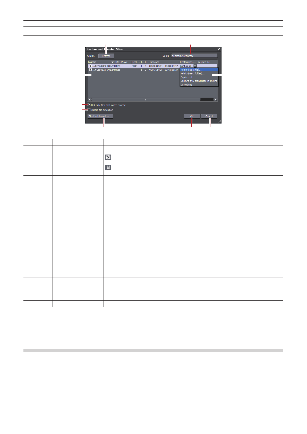
Chapter 2 Project Settings — Restoring Ofine Clips
(1) (2)
[Restore and Transfer Clips] Dialog Box
(3)
(4)
(5)
(6)
(7) (8) (9)
(1) [Refresh] Restore clips to which the restoration method is set.
(2) [Range] Select the target range of the clips from the list.
(3) Clip list
(4) [Restoration Method] [Relink (select le)]
(5) [Link only les that
match exactly]
(6) [Ignore le extension] Check this item to include les with different extensions for re-link.
(7) [Start batch capture] This item is enabled when either [Capture all] or [Capture only areas used in timeline] is
(8) [OK] Restore the ofine clips with the specied settings.
(9) [Cancel] Close the dialog box without restoring the ofine clips.
: Ofine clips
Clips whose links to the source are disconnected.
: Clips with restored links
Clips whose links to the source are restored.
The [Open] dialog box appears. Select the source to re-link.
[Relink (select folder)]
The [Browse For Folder] dialog box appears. Search the source with the same name in the
specied folder to re-link.
[Undo transfer]
Re-link the original source prior to the transition to the project folder.
[Capture all]
Click [Start batch capture] to display the [Batch Capture] dialog box to register the information
of the entire source.
“Importing Sources All Together (Batch Capture)” (w page 145)
[Capture only areas used in timeline]
Click [Start batch capture] to display the [Batch Capture] dialog box to register the clip
information used in the timeline.
[Do nothing]
Ofine clips are not re-linked or captured.
Check this item to specify only the les with exactly the same information in the original le to
be re-linked.
selected from the [Restoration Method] list.
Click this button to display the [Batch Capture] dialog box.
2
f You can change the default setting of [Restoration Method].
“[Restore Ofine Clip]” (w page 101)
Capturing and Restoring
If the source of the ofine clips does not exist in the hard drive, you can restore the clips by recapturing from the original source (recorded
tapes).
1)
In the [Restore and transfer clip] selected dialog box, click [Capture entire clip ] or [Capture only the
area used in timeline].
f The [Batch Capture] dialog box appears.
“Importing Sources All Together (Batch Capture)” (w page 145)
72
Page 73

Chapter 2 Project Settings — Restoring Ofine Clips
1 Alternative
f In the [Restore and Transfer Clips] dialog box, select either [Capture all] or [Capture only areas used in timeline] from the [Restoration
Method] list, and click [OK].
2)
Execute the batch capture.
Searching File by Reel Number to Restore
Search the source by reel number (Ubit) and timecode (between In and Out points) in already captured les.
1)
Click [Find from captured files] in the [Restore and transfer clip] selected dialog box.
f The [Restore Ofine Clip] dialog box appears.
f Search a le in a folder where the project is saved. If you cannot nd the le, click [Select Folder] and select a folder where the captured
les are stored, and click [OK].
2)
Click [Restore All].
f To restore selected les only, select a clip from [Find clip list] and click [Restore].
Restoring Clips That Cannot Reference Clip Part
The clips will be partial ofine clips under the following conditions: when a portion that forms a clip containing a proxy, when the proxy
created with EDIUS cannot be referenced, when a portion of the partially transferred clip cannot be referenced, or when either L or R side of
the stereoscopic clip that has the stream of both L and R sides in 2 les.
In EDIUS, you can proceed with “Proxy originated editing” in which you use a proxy source when editing, and replace it with a highresolution source before nal exporting. A proxy clip used in this proxy originated editing (a proxy clip with reference information in highresolution) is a “temporary editing clip”. A temporary editing clip can be easily replaced with a high-resolution clip using the source browser.
Example:
Partial ofine clip in the bin
Example:
Temporary editing clip in the bin
Example:
Partial ofine clip in the timeline
If there are partial ofine clips or temporary editing clips on the timeline, icons and the total number of the ofine clips, partial ofine clips,
and temporary editing clips (or untransferred clips) are displayed on the timeline status bar.
For P2, if a source le that only has a proxy (XML) is imported from the source browser, it will be recognized as an untransferred clip.
73
Page 74

Chapter 2 Project Settings — Restoring Ofine Clips
(1) (2)
3 Note
f If ofine clips, partial ofine clips, and temporary editing clips exist on the timeline when you expor t the project to a le or tape or when
consolidating or exporting the project, a message is displayed. Restore the ofine clips, partial ofine clips, or temporary editing clips.
Otherwise, they will be exported as ofine clips.
Restoring Partial Ofine Clips
Restore the partial ofine clips by retransfer the missing source or recreating the proxy. If needed, connect the device where the original
source is stored.
If either the L or R side of the stereoscopic clip cannot be referenced, perform the same restoration operations for ofine clips.
“Restoring Ofine Clips” (w page 70)
1)
Click the [Open Project] list button on the timeline.
2)
Click [Restore and Transfer Clips].
1 Alternative
f Click [File] on the menu bar, and click [Restore and Transfer Clips].
3)
Click [Open the clip restoration dialog] in the [Restore and transfer clip] selected dialog box.
f The [Restore and Transfer Clips] dialog box appears.
“[Restore and Transfer Clips] Dialog Box” (w pag e 74)
1 Alternative
f To restore the clips on the timeline only, double-click the ofine clip icon on the status bar.
4)
Select the target range of the clip from the [Range] list.
5)
Select a clip (or clips) from [Clip list], and select a restoration method from the [Restoration Method].
6)
Click [OK].
f The process is executed with the restoration method selected in [Restoration Method].
7)
Click [Close] in the [Restore and transfer clip] selected dialog box.
[Restore and Transfer Clips] Dialog Box
* The screen shown is an example The displayed restoration method varies according to the type of ofine clips.
(3)
(1) [Refresh] Click this button to refresh the clip list.
(4)
Restore clips to which the restoration method is set.
74
(5)
(6) (7)
Page 75

Chapter 2 Project Settings — Restoring Ofine Clips
(2) [Range] Select the target range of the clips from the list.
(3) Clip list
(4) [HiRes/Proxy] Display the type (high-resolution or proxy) of the ofine clips, partial ofine clips, and
(5) [Restoration Method] [Transfer the Missing Area]
(6) [OK] Restore the partial ofine clips or temporary editing clips with the specied settings.
(7) [Cancel] Close the dialog box without restoring the partial ofine clips or temporary editing clips.
: Ofine clip/Partial of ine clip
Clips whose links to the source are disconnected.
: Temporary editing clip
Camera proxy clips that have not been replaced by high-resolution clips.
: Untransferred clip
Clips where high-resolution/proxy streams exist on a camera (or card) and which have not
been transferred to a local terminal.
: Clips with restored links
Clips whose links to the source are restored.
temporar y editing clips.
Retransfer the missing portion from the device where the source le prior to the par tial transfer
is stored.
[Undo transfer]
Re-link to the source les prior to the par tial transfer.
[Create Proxy]
Recreate the proxy from high-resolution.
[Delete proxy]
Delete the proxy information of the clip.
[Relink (select le)]
The [Open] dialog box appears. Select the source to re-link.
[Relink (select folder)]
The [Browse For Folder] dialog box appears. Search the source with the same name in the
specied folder to re-link.
[Transfer All]
Transfer the whole high-resolution clip, regardless of the used range on the timeline.
[Transfer Only Used Area]
Transfer the untransferred high-resolution clip to the used range on the timeline.
[Capture all]
Restore clips with the batch capture function.
“Importing Sources All Together (Batch Capture)” (w page 145)
[Capture only areas used in timeline]
Restore only the area of the source in use with the batch capture function.
“Importing Sources All Together (Batch Capture)” (w page 145)
[Do nothing]
The ofine clips, partial ofine clips, and temporary editing clips are not restored.
2
f If [Transfer the Missing Area], [Create Proxy], [Transfer All], or [Transfer Only Used Area] has been selected as the restoration method,
the process is registered to the background job. Until the job is completed, the target clips remain partial ofine clips or temporary editing
clips.
f If you double -click the icon on the timeline status bar to display the [Restore and Transfer Clips] dialog box, only the ofine clips, partial
ofine clips, and temporary editing clips or untransferred clips on the timeline are displayed in [Clip list].
f You can use [Capture all] and [Capture only areas used in timeline] only when clips to be restored are capture-enabled formats and reel
names are set to clips.
f You can change the default setting of [Restoration Method].
“[Restore Ofine Clip]” (w page 101)
Restoring Temporary Editing Clips
A temporar y editing clip can be easily replaced with a high-resolution clip using the source browser.
1)
Import the media recording a high-resolution clip in the source browser.
f “Checking Files in External Devices that Interact with Source Browser” (w page 153)
2)
A message [Hi-res clips that match the proxy-only clips were found. Do you wish to replace them?]
appears, then click [Yes].
f A temporar y editing clip is replaced with a high-resolution clip automatically.
1 Alternative
f To restore the clips on the timeline only, double-click the ofine clip icon on the status bar.
“[Restore and Transfer Clips] Dialog Box” (w pag e 74)
75
Page 76

Chapter 3
Edit Settings
This chapter explains how to change editing operation and screen display settings, register the editing environment, register external
devices used for capture or tape output, and other operations.
76
Page 77

Chapter 3 Edit Settings — [System Settings]
[System Settings]
System settings allow you to manage project presets and proles, set input/output hardware, set input of sources and input/output of project
les, and other operations.
If you use the restricted user prole, the system settings cannot be changed.
“Restricted user prole” (w page 107)
The following explains the items that can be set in the system settings.
The settings can be changed even during editing.
[Application]
Set EDIUS operations.
[Audio Monitoring Mode]
Set audio output default value for monitoring on the Player or Recorder.
“Audio Monitoring” (w page 388)
1)
Click [Settings] on the menu bar, and click [System Settings].
2)
Click the [Application] tree, and click [Audio Monitoring Mode].
3)
Set each item.
[Player] [Default]
Set the default value of the audio monitoring mode for the Player when the project starts.
When [Off] is selected, the project starts without setting the audio monitoring mode.
[ChannelMap - Monaural]
Specify the default value by channel map when [Custom] is selected in [Audio Monitoring
Mode] and monaural clip is played back. To change the clip to be played back on the Player to
stereo, right-click on the track patch of the source channel and click [Audio Source Channel
(St ereo)]*.
[ChannelMap - Stereo]
Specify the default value by channel map when [Custom] is selected in [Audio Monitoring
Mode] and stereo clip is played back. To change the clip to be played back on the Player to
monaural, right-click on the track patch of the source channel and click [Audio Source Channel
(St ereo)]*.
[Recorder] [Default]
Set the default value of the audio monitoring mode for the Recorder when the project starts.
When [Off] is selected, the project starts without setting the audio monitoring mode.
[Channel map]
Specify the default value by channel map when [Custom] is selected in [Audio Monitoring
Mode].
* When [Audio Source Channel (Stereo)] is set, a frame appears around the button icon in the menu.
4)
Click [OK].
f You can continue to set other items by clicking [Apply].
[Playback]
Set playback operations.
1)
Click [Settings] on the menu bar, and click [System Settings].
2)
Click the [Application] tree, and click [Playback].
3)
Set each item.
[Stop Playback at Frame Drop] Stop the playback when playback processing cannot keep up with the playback speed.
[Playback Buffer Size] Specify the size of the buf fer used for realtime playback in MB (megabytes).
77
Page 78

Chapter 3 Edit Settings — [System Settings]
[Buffered Frames Before Playback] Set the number of frames buffered when starting playback. When playback stops because it
cannot keep up with the speed just after playback is started, the situation may be improved by
increasing the number of frames.
4)
Click [OK].
f You can continue to set other items by clicking [Apply].
[Capture]
Set EDIUS capture operations, processing at automatic detection of events, and other operations.
1)
Click [Settings] on the menu bar, and click [System Settings].
2)
Click the [Application] tree, and click [Capture].
3)
Set each item.
[Margin] Set the length of the margin added at In and Out points at capture operation.
[Conrm Reel Name Setting after
Setting Device Preset]
[Conrm File Name at Capture] Check and set the le name at a capture operation. If you select [Before Capture], you can set
[Load to Player after Capture] Play back the le created after capture automatically.
[Correct Audio Errors Automatically] Correct audio errors automatically at a capture operation.
[Set le names for 2 le Capture] If you create 2 les for the L side (for left eye) and the R side (for right eye) with 2 streams at
[Automatic Detection of Capture
Events]
[Deck Control after Capture] Select the deck state af ter capture operation from the list.
After a device preset is selected in the [Select Input Device] dialog box at a capture operation,
the dialog box for setting the reel name appears.
the destination and le name before performing capture. If you select [After Capture], you can
set the destination and le name after capture is nished.
stereoscopic source capture, set the sufx for the le name for L and R sides.
Select the conditions for automatically inserting cuts in les at capture operation. Cut insertion
conditions are as follows:
f [At Timecode Break]
f [When Aspect Ratio Changes]
f [When Sampling Rate Changes]
f [When the recorded Time Date Changes]
[When an Event is Detected]
Select how cut positions are processed.
If you select [Divide Files], les are divided at the cut position. If you check [Group Divided
Files as Sequence], multiple divided les are registered to the bin as a single sequence clip.
If you select [Add Marker], a clip marker is set at the cut position.
2
f Set voice over margins at [Margin] under [Capture].
4)
Click [OK].
f You can continue to set other items by clicking [Apply].
[Render]
Set the reference of rendering options or the timing to delete rendering les.
1)
Click [Settings] on the menu bar, and click [System Settings].
2)
Click the [Application] tree, and click [Render].
3)
Set each item.
78
Page 79

Chapter 3 Edit Settings — [System Settings]
[Render Options] Select the rendering target. For example, if you check [Filters] and a rendering option is set
when a lter is applied on a clip placed on the timeline, the area of that clip changes color to
yellow. By unchecking [Filters], the area will not change color to yellow. By default, all items
below are checked.
“Color Coding of Time Scale” (w page 278)
[Filters]
Select video lters as the rendering target.
[Transition/CrossFades]
Select transitions and title mixers as the rendering target.
[Key/Transparency]
Select key effect and transparency (when changed from the default) as the rendering target.
[Speed Change]
Select clips that feature any speed adjustments from the default value of 100% as the
rendering target.
[Contents that are not in the Project Format]
Select clips matching any of the following formats as the rendering target:
f Frame size different from that in the project
f Aspect ratio different from that in the project
f Frame rate different from that in the project
f Field order different from that in the project
f Compression format different from format handled by codec specied in the project settings
f Clip including alpha information
[Render Decisions] Check this item to perform rendering when the buffer becomes less than the set value in
[Buffer Left: Fewer than] at playback.
[Buffer Left: Fewer than]
Set the left of buffer value to be referenced for rendering decisions.
[Delete Invalid Rendered Files] Select the timing to delete rendering les.
f “Rendering Overload Areas of the Entire Sequence” (w page 279)
f “Rendering Overload Areas between In and Out Points” (w page 279)
4)
Click [OK].
f You can continue to set other items by clicking [Apply].
[Prole]
Register editing environments as proles and manage these proles.
“Editing Environment Management” (w page 104)
[Project Preset]
Create new project presets and manage project presets.
“Creating New Project Presets” (w page 51)
[Loudness Meter]
You can register reference to be used at the loudness measurement as a preset.
1)
Click [Settings] on the menu bar, and click [System Settings].
2)
Click the [Application] tree, and click [Loudness Meter].
3)
Click [Add].
4)
Set each item.
[Preset Name] Enter the name of the sequence.
[Momentary Gating] Enter the measurement time for the momentary value.
[Short-term Gating Block Size] Enter the measurement time for the short-term value.
[Overlap] Enter the overlap value.
[Relative Gating threshold] Enter the relative gating block level.
[Target Level] Enter the target level.
[Meter range] Set the meter range.
79
Page 80

Chapter 3 Edit Settings — [System Settings]
[Group 1]/[Group 2] Set the output channel assignments for L/R/C/LS/RS channels.
Set the assignment to both [Group 1] and [Group 2] to measure 2 groups simultaneously.
[Downmix]
Select an equation of the downmix process from the list.
[Add] Add a preset.
[Delete] Delete a preset.
[Register] Register the preset for the settings.
[Import]/[Export] Impor t/export the setting le for the loudness meter.
f “Measuring Volume” (w page 382)
5)
Click [Register].
6)
Click [OK].
f You can continue to set other items by clicking [Apply].
[Source Browser]
Set the transfer destination used when impor ting a le from the source browser.
1)
Click [Settings] on the menu bar, and click [System Settings].
2)
Click the [Application] tree, and click [Source Browser].
3)
Set each item.
[File transfer folder] Specify the transfer destination of the le. If [Custom folder] is selected, click [Browse] and
specify a transfer destination.
[Create folder with date] Check this item to create the date folder in the folder set in [File transfer folder].
[File transfer folder path] Display the path of the transfer destination. “%MediaType%” is the name of the source media to
be transferred by the source browser.
4)
Click [OK].
f You can continue to set other items by clicking [Apply].
[File export]
Make a setting to delete the last frame when exporting a le in 720/60p or 50p so that the number of the frames will be even. This setting is
applied to export and batch export operations.
1)
Click [Settings] on the menu bar, and click [System Settings].
2)
Click the [Application] tree, and click [File export].
3)
Set each item.
[Round of f to even frame when
exporting 60p/50p.]
4)
Click [OK].
f You can continue to set other items by clicking [Apply].
Check this item to delete the last frame when exporting a le in 60p/50p so that the number of
the frames will be even.
[SNFS QoS]
Restrict the SNFS bandwidth when loading les from the K2 Media server. This function allows to easily load a le without affecting the
other operations.
1)
Click [Settings] on the menu bar, and click [System Settings].
80
Page 81

Chapter 3 Edit Settings — [System Settings]
2)
Click the [Application] tree, and click [SNFS QoS].
3)
Set each item.
[Enable QoS.] Check this item to restrict the SNFS bandwidth.
Drive list The list of SNFS drives appears.
[Add] Click this item to display the [QoS] dialog box, then add an SNFS drive.
“[QoS] Dialog Box” ( w pa ge 81)
[Del] Delete an SNFS drive from the drive list.
[Modif y] Change the SNFS drive settings.
4)
Click [OK].
f You can continue to set other items by clicking [Apply].
[QoS] Dialog Box
[Drive] Select a drive to restrict the bandwidth.
[Bit Rate] Set the upper limit of the bandwidth.
[Check for updates]
If the updated EDIUS is released, the update information is automatically notied at the star tup of EDIUS.
1)
Click [Settings] on the menu bar, and click [System Settings].
2)
Click the [Application] tree, and click [Check for updates].
3)
Set each item.
[Check for online EDIUS updates.] Check this item to automatically notify of the release of the updated EDIUS at the startup.
“[Update Notication] Dialog Box” (w p age 81)
4)
Click [OK].
f You can continue to set other items by clicking [Apply].
[Update Notication] Dialog Box
[To update, click here.] Click this item to download the updater.
[Do not show this message for 30
days.]
Check this item not to automatically notify of the release of the updated EDIUS for the next 30
days.
1 Alternative
f When an updated EDIUS has been released, the [Update Notication] dialog box can be displayed by star ting up EDIUS, and then
clicking [Help] → [Check for updates] on the menu bar.
If the [Update Notication] dialog box is not displayed, you are using the updated EDIUS.
[Hardware]
Register external devices used for capture or tape output, or set external devices that are used for preview during editing.
“External Device Management” (w page 109)
[Importer/Exporter]
Make the settings for import and export.
81
Page 82

Chapter 3 Edit Settings — [System Settings]
[AVCHD]
Set faster seeking of AVCHD les.
1)
Click [Settings] on the menu bar, and click [System Settings].
2)
Click the [Importer/Exporter] tree, and click [AVCHD].
3)
Set each item.
[Use Accel. Seek] Set faster seeking of AVCHD les. To speed up seeking, check this item rst, and then check
the following items if necessary.
[Create Seek Information in Background]
Collect the time stamp information of AVCHD les at idling to speed up the seek.
[Save Seek Information to File]
Save the seek information as a reusable le.
[Get timecode from Picture Timing
SEI]
4)
Click [OK].
f You can continue to set other items by clicking [Apply].
Check this item to acquire the timecode information from Picture Timing SEI.
[Audio CD/DVD]
Make the setting for importing video or audio from CD/DVD disk.
1)
Click [Settings] on the menu bar, and click [System Settings].
2)
Click the [Importer/Exporter] tree, and click [Audio CD/DVD].
3)
Set each item.
[File Settings] Set the name for saving les imported from Audio CD or DVD (DVD -Video, DVD-VR).
[Set File Names Automatically.]
Automatically generate the le name by combining the current date/time and track number.
[Set File Names from Base File Name and Track Name.]
Automatically generate the le name by combining the base le name and track number. Check
this item to enable input of [Base Name].
[Audio CD Settings] Lower the audio level at import in dB units from the original volume.
[DVD Video Settings] Specify the dividing method at capture operation. Normally, select [At each Program].
[DVD-VR Settings] Specify the dividing method at capture operation. Normally, select [At each Program].
Select [At each Cell] to divide the le into small units. This, however, may create MPEG les
that sometimes cannot be played back (incompatible with the MPEG standard) when they are
imported depending on the stream.
4)
Click [OK].
f You can continue to set other items by clicking [Apply].
[Still Image]
Make the settings for exporting still images.
1)
Click [Settings] on the menu bar, and click [System Settings].
2)
Click the [Importer/Exporter] tree, and click [Still Image].
3)
Set each item.
82
Page 83

Chapter 3 Edit Settings — [System Settings]
[Capture Field] Though highest quality images are [Frame], rapid-moving images sometimes are blurred into
vertical comb -like stripes. If this happens, select [Upper Field] or [Lower Field].
[Filtering] Compensate for deteriorated image quality when [Upper Field] or [Lower Field] is selected
at [Capture Field]. [Motion Only] is suitable for partially blurred images, and [Full Screen] is
suitable for completely blurred images.
[Adjust Aspect] The aspect ratio differs for moving images handled in editing and still images handled on the
PC. Check this item to adjust the aspect ratio when displaying on a PC screen.
[File Type] Set the default le format for saving still images.
f “Exporting Still Image Clips from the Timeline” (w page 282)
f “Exporting a Still Image” (w page 403)
4)
Click [OK].
f You can continue to set other items by clicking [Apply].
[GF]
Set the reference folder when source les in GF devices are imported from the source browser window.
1)
Click [Settings] on the menu bar, and click [System Settings].
2)
Click the [Importer/Exporter] tree, and click [GF].
3)
Set each item.
[Source Folders] This is the list of references that is displayed in the source browser folder view.
GF sources can be handled as clips by the source browser by copying them to the hard disk
with the folder structure in the device held intact.
Click [Add] to set the reference folder. To delete a reference folder that has been set, select the
folder and click [Remove].
4)
Click [OK].
f You can continue to set other items by clicking [Apply].
[GXF]
Set the connections of FTP ser vers when outputting in the GXF format.
1)
Click [Settings] on the menu bar, and click [System Settings].
2)
Click the [Importer/Exporter] tree, and click [GXF].
3)
Set each item.
[Server List] Display a list of addresses of FTP servers set as export destinations.
[Add] Click this item to display the [FTP setting] dialog box for adding connection ser vers.
“[FTP setting] Dialog Box” (w page 84)
[Delete] Delete ser vers from [Server List].
[Modif y] Change the ser ver settings.
[Move Up]/[Move Down] Sort the servers.
Select a server from [Server List] and move the selected server one place up or down with
each click of [Move Up] or [Move Down].
[Settings] Display the settings of the connection selected in [Server List].
4)
Click [OK].
f You can continue to set other items by clicking [Apply].
83
Page 84

Chapter 3 Edit Settings — [System Settings]
[FTP setting] Dialog Box
[Name] Enter the name set for the server.
[Address] Enter the IP address or server name of the FTP server.
[Por tNo] Enter the port number. The default port number is 21.
[Directory] Enter the directory name of the export destination.
[Username]/[Password] Enter the user name and password required when making the connection.
[Connection Test] Click this item to test the connection to the FTP server using the currently entered user name
and password.
[RED]
Set an image quality for playback of sources in RED format.
1)
Click [Settings] on the menu bar, and click [System Settings].
f The [System Settings] dialog box appears.
2)
Click the [Importer/Exporter] tree, and click [RED].
3)
Set each item.
[Preview Quality] Set the playback image quality.
Select [1/1] to retain the source resolution.
Select [1/2], [1/4], [1/8], or [1/16] to reduce the image quality to 1/2, 1/4, 1/8, or 1/16 of the
source horizontal resolution respectively.
4)
Click [OK].
f You can continue to set other items by clicking [Apply].
[Innity]
Set the reference folder when source les in Innity devices are imported from the source browser window.
1)
Click [Settings] on the menu bar, and click [System Settings].
2)
Click the [Importer/Exporter] tree, and click [Infinity].
3)
Set each item.
[Source Folders] This is the list of references that is displayed in the source browser folder view.
Innity sources can be handled as clips by the source browser by copying them to the hard disk
with the folder structure in the device held intact.
Click [Add] to set the reference folder. To delete a reference folder that has been set, select the
folder and click [Remove].
4)
Click [OK].
f You can continue to set other items by clicking [Apply].
[K2 (FTP)]
K2 (FTP) FTP Server Settings
Set up FTP server connections before importing sources on the K2 Media server.
1)
Click [Settings] on the menu bar, and click [System Settings].
84
Page 85

Chapter 3 Edit Settings — [System Settings]
2)
Click the [Importer/Exporter] tree, and click [K2 (FTP)] → [FTP Server].
3)
Set each item.
[Server List] This is the list of K2 Media ser vers that is displayed in the source browser folder view.
[Add] Click this item to display the [FTP setting] dialog box for adding connection ser vers.
“[FTP setting] Dialog Box” (w page 85)
[Delete] Delete ser vers from [Server List].
[Modif y] Change the ser ver settings.
[Move Up]/[Move Down] Sort the list.
Select a server from [Server List] and move the selected server one place up or down with
each click of [Move Up] or [Move Down].
[Setting] Display the settings of the connection selected in [Server List].
4)
Click [OK].
f You can continue to set other items by clicking [Apply].
[FTP setting] Dialog Box
[Name] Enter the name of the ser ver to display in the folder view.
[Address] Enter the address of the server.
[Folder] The address of the bin is entered. Normally, there is no need to change the frame rate.
[Username]/[Password] Enter the user name and password required when making the connection.
[Connection Test] Click this item to test the connection to the FTP server using the currently entered user name
and password.
K2 (FTP) Browser Settings
Set items that are allowed when connecting to the K 2 Media server.
1)
Click [Settings] on the menu bar, and click [System Settings].
2)
Click the [Importer/Exporter] tree, and click [K2 (FTP)] → [Browser].
3)
Set each item.
[Multi Connection/Multi Conversion] [Max Number of Connections]
Set the maximum number of clips to be downloaded simultaneously from the K2 Media server.
When [Allow Multiple Connections to the Same Server.] is checked, the same server can be
connected to simultaneously.
[Max Number of Conversions]
Set the maximum number of clips to be converted simultaneously.
[Allows Users to Rename/Delete
Clips.]
4)
Click [OK].
f You can continue to set other items by clicking [Apply].
Check this item to enable changes to and deletion of clips in the server.
[MPEG]
Set faster seeking of MPEG les.
1)
Click [Settings] on the menu bar, and click [System Settings].
2)
Click the [Importer/Exporter] tree, and click [MPEG].
3)
Set each item.
85
Page 86

Chapter 3 Edit Settings — [System Settings]
[Use Accel. Seek] Set faster seeking of MPEG les. To speed up seeking, check this item rst, and then check
the following items if necessary.
[Create Seek Information in Background]
Collect the time stamp information of MPEG les at idling to speed up the seek.
[Save Seek Information to File]
Save the seek information as a reusable le.
[A/V Synchronization Using PTS] Check this item to use the PTS (time stamp information) for synchronization of audio and video.
[Get Timecode from GOP Header] Some MPEG les may have timecode information in their header. Check this item to use
timecode information.
4)
Click [OK].
f You can continue to set other items by clicking [Apply].
[MXF]
MXF FTP Server Settings
Set the connections of FTP ser vers when outputting in the MXF format.
1)
Click [Settings] on the menu bar, and click [System Settings].
2)
Click the [Importer/Exporter] tree, and click [MXF] → [FTP Server].
3)
Set each item.
f The [FTP Server] setting items for MXF are the same as for GXF.
“[GXF]” (w page 83)
4)
Click [OK].
f You can continue to set other items by clicking [Apply].
MXF Decoder Settings
You can set the layer and downsample coefcient to be decoded when importing MXF les in the JPEG2000 format.
1)
Click [Settings] on the menu bar, and click [System Settings].
2)
Click the [Importer/Exporter] tree, and click [MXF] → [Decoder].
3)
Set each item.
[Qualit y] Specify a layer to decode.
[High]
Decode all layers.
[Middle]
Decode half of the layers.
[Low]
Decode single layer.
[Downsampling Ratio] Specify a downsample (scaling) coefcient at decoding.
4)
Click [OK].
f You can continue to set other items by clicking [Apply].
[P2]
P2 Browser Settings
Set the reference folder when source les in P2 devices are imported from the source browser window.
86
Page 87

Chapter 3 Edit Settings — [System Settings]
1)
Click [Settings] on the menu bar, and click [System Settings].
2)
Click the [Importer/Exporter] tree, and click [P2] → [Browser].
3)
Set each item.
[Source Folders] This is the list of references that is displayed in the source browser folder view.
P2 sources can be handled as clips by the source browser by copying them to the hard disk
with the folder structure in the device held intact.
Click [Add] to set the reference folder. To delete a reference folder that has been set, select the
folder and click [Remove].
4)
Click [OK].
f You can continue to set other items by clicking [Apply].
[Removable Media]
Set the reference folder when source les in removable media are impor ted from the source browser window.
1)
Click [Settings] on the menu bar, and click [System Settings].
2)
Click the [Importer/Exporter] tree, and click [Removable Media].
3)
Set each item.
[Source Folders] This is the list of references that is displayed in the source browser folder view.
Source les can be handled as clips by the source browser by copying them to the local disk
(hard disk) with the folder structure in the media held intact.
Click [Add] to set the reference folder. To delete a reference folder that has been set, select the
folder and click [Delete].
4)
Click [OK].
f You can continue to set other items by clicking [Apply].
[XDCAM EX]
Set the reference folder when source les in XDCAM EX devices are imported from the source browser window.
1)
Click [Settings] on the menu bar, and click [System Settings].
2)
Click the [Importer/Exporter] tree, and click [XDCAM EX].
3)
Set each item.
[Source Folders] This is the list of references that is displayed in the source browser folder view.
Source les can be handled as clips by the source browser by copying them to the local disk
(hard disk) with the folder structure in the device held intact.
Click [Add] to set the reference folder. To delete a reference folder that has been set, select the
folder and click [Delete].
4)
Click [OK].
f You can continue to set other items by clicking [Apply].
87
Page 88

Chapter 3 Edit Settings — [System Settings]
[XDCAM]
XDCAM Connection Settings
Set up FTP server connections before downloading and importing XDCAM sources from the server.
1)
Click [Settings] on the menu bar, and click [System Settings].
2)
Click the [Importer/Exporter] tree, and click [XDCAM] → [FTP Server].
3)
Set each item.
[Server List] This is the list of XDCAM servers that is displayed in the source browser folder view.
[Add] Click this item to display the [FTP setting] dialog box for adding connection ser vers.
“[FTP setting] Dialog Box” (w page 88)
[Remove] Delete servers from [Server List].
[Modif y] Change the ser ver settings.
[Move Up]/[Move Down] Sort the list.
Select a server from [Server List] and move the selected server one place up or down with
each click of [Move Up] or [Move Down].
[Settings] Display the settings of the connection selected in [Server List].
4)
Click [OK].
f You can continue to set other items by clicking [Apply].
r [FTP setting] Dialog Box
[Name] Enter the name of the ser ver to display in the folder view.
[Address] Enter the IP address or server name of the FTP server.
[Username]/[Password] Enter the user name and password required when making the connection.
[Directory] Select a directory type from the list.
[Connection Test] Click this item to test the connection to the FTP server using the currently entered user name
and password.
2
f If connection fails by the connection test, try restarting the XDCAM device and PC after completing the FTP server connection setup.
XDCAM Importer Settings
Set whether to use high-resolution audio to edit proxy.
1)
Click [Settings] on the menu bar, and click [System Settings].
2)
Click the [Importer/Exporter] tree, and click [XDCAM] → [Importer].
3)
Set each item.
[When proxy is edited, high-resolution
audio is used if available.(VFAM drive
only)]
4)
Click [OK].
f You can continue to set other items by clicking [Apply].
For data on VFAM drive, use high-resolution audio data to edit proxy.
XDCAM Browser Settings
Set the clip type, clip name and other settings when clips are imported before importing XDCAM sources.
88
Page 89

Chapter 3 Edit Settings — [System Settings]
1)
Click [Settings] on the menu bar, and click [System Settings].
2)
Click the [Importer/Exporter] tree, and click [XDCAM] → [Browser].
3)
Set each item.
[Download] Select the data (proxy/high-resolution) to be downloaded from the source browser.
“Importing from XDCAM Devices” (w p ag e 161)
“Importing XDCAM Sources from a Ser ver” (w page 162)
“Downloading XDCAM Sources and Simultaneously Placing Them on the Timeline”
(w page 163)
[When Transfer to Bin]
Select the data to be downloaded when transferring to the bin. Select [All] to download both
high-resolution and proxy.
[When Add to Timeline]
Select the data to be downloaded when placing clips on the timeline. Select [All] to download
both high-resolution and proxy.
[Source Folders] This is the list of references that is displayed in the source browser folder view.
XDCAM sources can be handled as clips by the source browser by copying them to the hard
disk with the folder structure in the device held intact.
Click [Add] to set the reference folder. To delete a reference folder that has been set, select the
folder and click [Remove].
[Thumbnail] Set whether to display thumbnails in the clip list in the source browser.
[Show Thumbnails when Connecting to FTP]
Display thumbnails when making a connection to the FTP server.
[Show Thumbnails when Connecting to XDCAM Drive]
Display thumbnails when making a connection to the XDCAM device.
[Register Name] Select the name to register to the bin from [Clip Title] or [Clip Name].
2
f Even when [Thumbnail] is unchecked, thumbnails are sometimes displayed for clips, etc. that have been displayed as thumbnails even
once.
4)
Click [OK].
f You can continue to set other items by clicking [Apply].
[XF]
Set the reference folder when source les in XF devices are imported from the source browser window.
1)
Click [Settings] on the menu bar, and click [System Settings].
2)
Click the [Importer/Exporter] tree, and click [XF].
3)
Set each item.
[Source Folders] This is the list of references that is displayed in the source browser folder view.
XF sources can be handled as clips by the source browser by copying them to the hard disk
with the folder structure in the device held intact.
Click [Add] to set the reference folder. To delete a reference folder that has been set, select the
folder and click [Remove].
4)
Click [OK].
f You can continue to set other items by clicking [Apply].
[Datacam]
Set the reference folder when source les in Datacam devices are imported from the source browser window.
1)
Click [Settings] on the menu bar, and click [System Settings].
89
Page 90

Chapter 3 Edit Settings — [System Settings]
2)
Click the [Importer/Exporter] tree, and click [Datacam].
3)
Set each item.
[Source Folders] This is the list of references that is displayed in the source browser folder view.
Datacam sources can be handled as clips on the source browser by copying them to the hard
disk with the folder structure in the device held intact.
Click [Add] to set the reference folder. To delete a reference folder that has been set, select the
folder and click [Remove].
4)
Click [OK].
f You can continue to set other items by clicking [Apply].
[Dolby Digital]
Make the settings for exporting Dolby Digital.
1)
Click [Settings] on the menu bar, and click [System Settings].
2)
Click the [Importer/Exporter] tree, and click [Dolby Digital].
3)
Set each item.
[Dynamic Range Control] Set the operation mode of the dynamic range when Dolby Digital Professional and Dolby
Digital Plus are imported.
4)
Click [OK].
f You can continue to set other items by clicking [Apply].
[K2 (SAN)]
K2 (SAN) Project Importer Settings
“K2 Project Importer Settings” (w page 433)
K2 (SAN) Server Settings
“K2 Server (SAN) Settings” (w page 432)
K2 (SAN) Browser Settings
“Browser Settings” (w page 433)
[Effects]
Set up effect plug-ins.
[After Effects Plug-in Bridge]
In EDIUS, as well as plug-ins by third parties that support EDIUS, other plug-ins for After Effects can be added using the After Effects plugin bridge function.
3 Note
f Not all After Effects plug-in operations are guaranteed.
f Only 64 bit After Effects plug-ins are supported. If EDIUS has been upgraded from an older version, add a 64 bit After Effects plug-in.
90
Page 91

Chapter 3 Edit Settings — [System Settings]
1)
Click [Settings] on the menu bar, and click [System Settings].
2)
Click the [Effects] tree, and click [After Effects Plug-in Bridge].
3)
Set each item.
[Add] Specify the folder containing the Af ter Effects plug-in and add to [After Effects Plug-in Search
Folder]. Restart EDIUS after registration.
[Delete] Delete folders from [After Effects Plug-in Search Folder].
[Unsupported Plug-in List] Plug-ins that could not be imported in [After Effects Plug-in Search Folder] and the error details
are listed.
4)
Click [OK].
f You can continue to set other items by clicking [Apply].
After Effects Plug-in Registration
Save the After Effects plug-in le in any folder on your PC.
1)
Click [Add] at [After Effects Plug-in Bridge].
2)
In the [Browse For Folder] dialog box, select the folder containing the After Effects plug-in and click
[OK].
f The folder is registered, and is displayed in [After Effects Plug-in Search Folder].
3)
Click [OK], and restart EDIUS.
f The After Effects folder is registered to [Video Filter] in the [Effect] palette.
You can select After Effects plug-ins from the After Effects folder.
f When new les for After Effects plug-ins have been added to the folder registered in step 2), you do not need to register the folder again.
f To delete a registered folder, select a folder to be deleted in step 1), and click [Delete].
[GPUfx]
Make settings for GPUfx.
1)
Click [Settings] on the menu bar, and click [System Settings].
2)
Click the [Effects] tree, and click [GPUfx].
3)
Set each item.
[Multisample] Set antialiasing (processing to make jaggies less conspicuous) when GPUfx is applied.
[Multisample Type]
Select an available multisample type.
[Quality Level]
Set the quality level of the type selected at [Multisample Type].
Selectable items differ according to the type of GPU.
[Render Quality] Set the image quality at editing of par ts where GPUfx is applied.
When [Full Quality] is selected, GPU is used and displayed at its maximum.
When [Draft Quality] is selected, the load at editing can be reduced though this results in lower
quality.
GPU performance Displays the GPU of your PC.
“GPUfx Transition Operating Environment” (w page 92)
3 Note
f GPUfx cannot be used if video memory on your PC is smaller than 256 MB. The [GPU] folder also will not be displayed on the [Effect]
palette.
f Editing is possible at HD size even in environments where only the SD size can be used. In this case, GPUfx transition becomes
ofine display.
91
Page 92

Chapter 3 Edit Settings — [System Settings]
4)
Click [OK].
f You can continue to set other items by clicking [Apply].
GPUfx Transition Operating Environment
To use GPUfx transition, the following conditions are required:
f Display capability of 1024x768 pixels and 32 bits or more
f Direct3D 9.0c or later
f PixelShader3.0 or higher
f For video memory, see the following table.
Project setting Video memory
Frame size Quantization bitrate Minimum Recommended
SD size 8 bits 256 MB 512 MB
10 bits 512 MB 1 GB
HD size 8 bits 512 MB 1 GB
10 bits 1 GB 2 GB
Over HD size 8 bits/10 bits 2 GB 2 GB
[VST Plug-in Bridge]
In EDIUS, as well as plug-ins by third parties that support EDIUS, other plug-ins that support VST can be added using the VST plug-in
bridge function.
3 Note
f Not all VST plug-in operations are guaranteed.
f Only 64 bit VST plug-ins are supported. If EDIUS has been upgraded from an older version, add a 64 bit VST plug-in.
1)
Click [Settings] on the menu bar, and click [System Settings].
2)
Click the [Effects] tree, and click [VST Plug-in Bridge].
3)
Set each item.
[Add] Specify the folder containing the VST plug-in to add to [Add VST Plug-ins]. Restart EDIUS after
[Delete] Delete folders from [Add VST Plug-ins].
4)
Click [OK].
f You can continue to set other items by clicking [Apply].
registering the folder.
VST Plug-in Registration
Save the DLL le of the VST plug-in in any folder on your PC.
1)
Click [Add] at [VST Plug-in Bridge].
2)
In the [Browse For Folder] dialog box, select the folder containing the VST plug-in and click [OK].
f The folder is registered, and is displayed at [Add VST Plug-ins].
3)
Click [OK], and restart EDIUS.
f The VST folder is registered to [AudioFilters] on the [Effect] palette.
You can select VST plug-ins from the VST folder.
f When new DLL les for VST plug-ins have been added to the folder registered in step 2), you do not need to register the folder again.
f To delete a registered folder, select a folder to be deleted in step 1), and click [Delete].
92
Page 93

Chapter 3 Edit Settings — [System Settings]
1 Alternative
f Directly copy DLL les for VST to the “EDIUS 7” → “PlugIn” → “VST” folder on the hard disk where EDIUS is installed.
Normally, the “EDIUS 7” folder is located in “C drive” → “Program Files” → “Grass Valley”.
[Input Controller]
[Fader]/[Jog Device]
Assign ports to use the option fader controller and jog controller.
The following products are also supported in addition to the option products:
f Behringer fader controller “BCF2000”
f HDWS/REXCEED series option “MKB-88 for EDIUS”
2
f Assign keys to controller buttons in the user settings.
“[Input Controller]” (w page 102)
1)
Click [Settings] on the menu bar, and click [System Settings].
2)
Click the [Input Controller] tree, and click [Fader] or [Jog Device].
3)
Set each item.
[Device] Select the controller to use.
[Port] Select the port to assign to the controller. After selecting a port, click [Reconnect].
4)
Click [OK].
f You can continue to set other items by clicking [Apply].
93
Page 94

Chapter 3 Edit Settings — [User Settings]
34
[User Settings]
Change how clips are handled on the timeline, or change the user editing environment, for example, by customizing screens or buttons.
Both restricted users and administrator users can change and save settings in proles from any user prole.
The following explains the items that can be set in the user settings.
The settings can be changed even during editing.
[Application]
Set EDIUS operations.
[Timeline]
Set operation or display on timeline.
1)
Click [Settings] on the menu bar, and click [User Settings].
2)
Click the [Application] tree, and click [Timeline].
3)
Set each item.
[Extend Clips when Applying
Transition/Cross Fade]
[Insert Default Crossfade in
Transition]
[Insert Default Transition in
Crossfade]
[Set the Cut Point of Transition/Cross
Fade to Front when at Middle of a
Frame]
[Hold the Next Clip when Trimming a
Clip (except at ripple trim)]
[Show Tool Tip During the Trim] Display timecode information on the tooltip while dragging to trim the cut point of clips.
[Reset Pan Settings when Audio Clips
are Moved to Other Tracks]
[Select the Left Clip when Cutting a
Clip]
[Snap Event] Enable the snap function.
[Default] Change the default setting for the editing mode when creating a new project le.
[Waveform] Set the display method for the waveform of the timeline to either [Log (dB)] or [Linear (%)].
[Clip Timecode] Display the checked timecode on the clip.
[Clip Thumbnail] Display the thumbnails of In/Out points at the clip edge on the timeline. Select [All] to display
When a clip transition/audio cross fade has been set to the clip on the timeline, right and left
clips extend and overlap with each other. The total length remains unchanged.
“Extend/Fix mode” (w page 213)
When a transition has been set to a video clip on a VA track, the default audio cross fade of the
same length is simultaneously added to the audio clip at the same position.
“Changing Default Effects” (w pa ge 321)
When a cross fade has been set to an audio clip on a VA track, the default transition of the
same length is simultaneously added to the video clip at the same position.
“Changing Default Effects” (w pa ge 321)
Set the cut points of clip transitions or audio cross fades to forward. For example, when the
transition for 7 frames has been set, the cut points are set bet ween the third and fourth frames.
Disable extension of clips across the edge of the clips on the left and right when trimming a clip
with ripple mode off.
When an audio clip has been moved or copied to another track, the pan setting is reset aligned
with the move destination track. For example, when a clip on the A1 track has been moved
to the A2 track, the pan that was set on the A1 track is reset on the A2 track with the L and R
sides inverted.
Set which one of the previous and next clips will be selected when clip cutting has been
performed.
Check the event to be used as the snap point. When [Snap to Events Inside the Selected Area]
is checked, all edit points of the clip in the selection area are snapped to.
“Switching the Mode when Placing/Moving Clips” (w page 210)
thumbnails in succession. To hide thumbnails, uncheck this item.
[Alt] + [H]
4)
Click [OK].
f You can continue to set other items by clicking [Apply].
94
Page 95

Chapter 3 Edit Settings — [User Settings]
[Match Frame]
Set the search direction or track.
1)
Click [Settings] on the menu bar, and click [User Settings].
2)
Click the [Application] tree, and click [Match Frame].
3)
Set each item.
[Search Direction] Select the direction for searching clips when [Match Frame (Player to Recorder)] is clicked.
After searching to the end, the search resumes from the beginning.
[Target Tracks] Specif y the track to be searched. Each track can be specied by selecting [Choose Tracks] or
[Selected Tracks].
[Transition] When you execute a match frame at the point where a transition is set, set whether to use a
front side clip or back side clip.
f “Match Frame” (w page 276)
4)
Click [OK].
f You can continue to set other items by clicking [Apply].
[Background Job]
Set background processing during playback.
1)
Click [Settings] on the menu bar, and click [User Settings].
2)
Click the [Application] tree, and click [Background Job].
3)
Set each item.
[Default Settings for Background Job] [Pause Background Jobs During Playback]
Check this item to pause the execution of the job when the Player or timeline is played back
during execution of a background job.
3 Note
f Copying is paused depending on settings even if multiple drives are connected and the drive that is copying is different from the drive
that is playing back.
4)
Click [OK].
f You can continue to set other items by clicking [Apply].
Proxy Mode Settings
Set operations in the proxy mode.
1)
Click [Settings] on the menu bar, and click [User Settings].
2)
Click the [Application] tree, and click [Proxy Mode].
3)
Set each item.
[Proxy Mode] [ When there is No Proxy, Use HiRes]
Check this item to use high-resolution when there are no proxies in the clip.
[Automatically Generate Proxy]
Check this item to generate a proxy automatically in the background when no proxies are found
when the proxy mode is set.
95
Page 96

Chapter 3 Edit Settings — [User Settings]
4)
Click [OK].
f You can continue to set other items by clicking [Apply].
3 Note
f When both [ When there is No Proxy, Use HiRes] and [Automatically Generate Proxy] are unchecked, operation is as follows:
g When the proxy mode is set, clips without a proxy become ofine clips.
g All clips become ofine clips when a project le from which only the proxy has been exported by the export function of the project is
opened on a PC that does not have EDIUS Elite or EDIUS Pro license.
[Project le]
Set project le save destinations, backup/auto save, and other settings.
1)
Click [Settings] on the menu bar, and click [User Settings].
2)
Click the [Application] tree, and click [Project file].
3)
Set each item.
[Project File] [Project File Folder]
Change the folder currently selected as the save destination for project les. Select the folder
from the [Browse For Folder] dialog box displayed by clicking [Browse].
[File Name]
Change the default project le name that is given when a new project is created. To rename the
le, enter a new name in the text box.
[Recent Project] [Show the MRU List]
Display the list of history les from the [Recent Project] list in the [Start Project] dialog box,
or by clicking the [Open Project] list button, or by clicking [File] on the menu bar → [Recent
Project]. Set the number of history les to display by [Number of Files].
[Backup] [Destination]
Check this item to automatically create a backup le.
When [Project Folder] is checked, a backup le is saved in “Project” → “Backup” in the project
fo lde r.
When [Select a Folder] is checked and [Browse] is clicked, another save destination can
also be specied. In this case, the backup le will be saved in “specied save destination” →
“project name” → “Bac kup”.
[Number of Files]
Set the maximum number of backup les that are created.
[Auto Save] [Destination]
Check this item to automatically save project les.
Check [Project Folder] to save an auto save le in “Project” → “AutoSave” in the project folder.
When [Select a Folder] is checked and [Browse] is clicked, another save destination can
also be specied. In this case, the backup le will be saved in “specied save destination” →
“project name” → “AutoSave”.
[Number of Files]
Set the maximum number of auto save les that are created.
[Interval]
Specify the time interval for executing auto-save.
[Delete All Auto Save Files when the Project File is Saved.]
Check this item to delete the auto save le after the project le is saved.
4)
Click [OK].
f You can continue to set other items by clicking [Apply].
[Other]
Set how to display the history le or set existing titlers.
1)
Click [Settings] on the menu bar, and click [User Settings].
2)
Click the [Application] tree, and click [Other].
96
Page 97

Chapter 3 Edit Settings — [User Settings]
3)
Set each item.
[Recent clip] [Show the Recently Used List]
Click [File] on the menu bar → [Recent clip] to display the list of history clips. Set the number of
history clips to display by [Number of Files].
[Show Thumbnail in the MRU List]
Click [File] on the menu bar → [Recent clip] to display thumbnails. To display thumbnails, select
the size from [Large] or [Small].
[Save Window Positions] Reproduce the last window and palette positions at the next start-up.
[Show Tooltip] Displays the tooltip when the mouse cursor is moved over effect names.
[Create Waveform cache when
registering clip]
[Create waveform cache les in
Project folder (for les in removable
or network drives)]
[Set anchor setting to ON when
adding a new sequence marker.]
[Player Format] Select the format ([Source Format]/[Timeline Format]) for the Player to be used in le playback.
[Default Titler] Select the titler (software for creating titles) that is started up when [Create Title] for the bin or
4)
Click [OK].
f You can continue to set other items by clicking [Apply].
Check this item to create waveform cache (waveform representation of audio) when registering
a clip.
Check this item to copy wave form cache (waveform representation of audio) on the removable
drive or network drive to the project folder.
Check this item to enable the anchor setting when adding sequence markers.
“Sync-Lock Setting of Sequence Marker” (w page 268)
On HD video monitors, SD signals may not be displayed.
timeline is clicked.
[Preview]
Set up display of the preview window.
[Playback]
Set the preliminary operation time during playback or playback operation.
1)
Click [Settings] on the menu bar, and click [User Settings].
2)
Click the [Preview] tree, and click [Playback].
3)
Set each item.
[Preroll] Set preliminar y operation (preroll), for example, when playing back near the timeline cursor or
when star ting recording on a voice recorder.
“Playing Back the Area around the Timeline Cursor” (w page 275)
“Addition of Speech with Voice Over” (w page 386)
[Continue Playback when Editing]/
[Continue Playback when Adding to
the Timeline from Player]/[Continue
Playback when Trimming Clip]
[Show Correct Frame when
Scrubbing]
[Combine Filter Layers and Track
Layers (for effect settings)]
[Output Timecode] Select the timecode that is output when outputting les or tapes.
Continue playback even when each editing operation is executed during timeline playback.
Display the image of the specied frame at all times even while scrubbing (dragging the
timeline cursor with the mouse). When this item is unchecked, some of the frame images are
displayed skipped. This setting is ef fective when scrubbing MPEG les or Windows Media
Video les.
Check this item to display composite clips to which effects are applied when previewing in
the effect setting dialog box. For example, if this item is checked, the composite image of V1
and V2 video will be displayed when you open the setting dialog box for the video lter that is
applied to the V1 track after placing clips in the V1 and V2 tracks. If this item is unchecked, only
the image of the V1 track is displayed.
“Setting Effects” (w page 307)
97
Page 98

Chapter 3 Edit Settings — [User Settings]
[Source Timecode Priority] When the source timecode is output or displayed, set the track to display the timecode for from
the tracks that have clips with timecode information placed on them, including T tracks.
[Upper Track]
[Lower Track]
[Source audio pass through and
ancillary data priority]
When expor ting audio bitstream or ancillary data (including closed caption), set the track to
export from the tracks on which the clips with those information are placed (including T track).
* The ancillary data playback is supported only when STORM 3G ELITE or STORM 3G is used.
3 Note
f Even when [Lower Track] is selected in [Source Timecode Priority], the source timecode of the lower track is not displayed if the
transparency of the upper track is not set (i.e. transparency is 100%).
4)
Click [OK].
f You can continue to set other items by clicking [Apply].
[Monitor]
Set the display content in full screen view on the monitor or in stereoscopic edit mode.
1)
Click [Settings] on the menu bar, and click [User Settings].
2)
Click the [Preview] tree, and click [Monitor].
3)
Set each item.
f Once the display content of each monitor is set, no further setting is needed from the next time.
[No.] Enter the monitor number. Monitor numbers from “2” onwards are external monitors.
[Full Screen Preview Contents] [Full Screen Preview Contents]
Displays content of the full screen view.
Click the list to display a menu and change display content for each monitor.
[No full screen preview]
Disable the full screen view.
[Player/Multicam Source]
Display the Player screen in full screen view. In the multicam mode, the videos of each track
with camera assigned are displayed in full screen view.
[Recorder/Selected Camera]
Display the Recorder screen in full screen view. In the multicam mode, the video of the
selected camera is displayed in full screen view.
[Auto]
Display the same screen as video output in full screen view.
[Stereoscopic ip horizontal] Check this item to display video with the L side (for left eye) and R side (for right eye) swapped.
[Using NVIDIA 3D VISION/Intel InTru
3D]
[Monitor Check] Click this item to display the monitor number on the respective monitor.
If your system supports NVIDIA 3D VISION or Intel Intru 3D, check this item to enable the
stereoscopic view ([L/R Dual Stream]) using NVIDIA 3D VISION or Intel Intru 3D on the
primary monitor.
3 Note
f NVIDIA 3D VISION or Intel Intru 3D can be used only in D3D full screen mode.
It takes a while to display the stereoscopic video on the monitor.
f 3D VISION is applied only to the primary monitor.
4)
Click [OK].
f You can continue to set other items by clicking [Apply].
98
Page 99

Chapter 3 Edit Settings — [User Settings]
[On Screen Display]
Set display of the timecode and level meter on the status area.
1)
Click [Settings] on the menu bar, and click [User Settings].
2)
Click the [Preview] tree, and click [On Screen Display].
3)
Set each item.
[Show Normal Edit]/[Show Trim]/
[Show Export]
[View] [Position]
[Select Source Information] For captured clips, display information such as recording date. Select the information to display
[Show Level Meter] Switch the show/hide setting for the level meter. Click [Default] to return to the default settings.
4)
Click [OK].
f You can continue to set other items by clicking [Apply].
Check the timecodes or information to display at each operation.
Click the display position inside the monitor on the status bar to select the position.
[Size]
Select the font size of the status bar.
[Background]
Check this item to display the background on the status bar display area.
from the list.
[Color and Threshold]
Set the color and threshold value of the level meter. Click a color sample to open the [Color
Select] dialog box.
[Invert Meter at Peak]
Select whether to invert the level meter when it peaks.
2
f The source timecodes of muted tracks are not displayed.
[Pre-Roll Editing]
Set preroll and postroll when editing preroll.
1)
Click [Settings] on the menu bar, and click [User Settings].
f The [User Settings] dialog box appears.
2)
Click the [Preview] tree, and click [Pre-Roll Editing].
3)
Set each item.
[Preroll Time] Set the preliminar y operation time (preroll) when editing preroll.
[Postroll] Set the preliminary operation time (postroll) when editing preroll.
f “Previewing Cut Switch Points (Preroll Edit (Preview))” (w page 221)
f “Placing Clips while Checking Cut Switch Points (Preroll Edit (Rec))” (w page 222)
4)
Click [OK].
f You can continue to set other items by clicking [Apply].
[Overlay]
Set the screen refresh rate, zebra preview (warning indication for brightness level) and display of the safe area.
1)
Click [Settings] on the menu bar, and click [User Settings].
2)
Click the [Preview] tree, and click [Overlay].
99
Page 100

Chapter 3 Edit Settings — [User Settings]
3)
Set each item.
[Update Frequency] Set the refresh rate for the video preview screen. When displaying interlaced images,
movement of subjects may be smoothed and accidents (such as reversed eld orders) can then
be checked visually by refreshing the screen at the eld rate (twice as fast as the frame rate).
(There is no difference between both settings when displaying progressive images.)
[Field]
For example, in the case of 29.97 fps frame rate, the screen is refreshed 59.94 times per
second.
[Frame]
For example, in the case of 29.97 fps frame rate, the screen is refreshed 29.97 times per
second.
[Zebra Preview] A striped pattern is displayed at relevant parts of the screen when the brightness level set at
this item is exceeded.
[Over]
Set the upper limit of the brightness level. Select [Color] of the stripe pattern that is displayed
when the upper limit of the brightness level is exceeded.
[Under]
Set the lower limit of the brightness level. Select [Color] of the stripe pattern that is displayed
when the lower limit of the brightness level is exceeded or brightness falls to 0 IRE or below.
[Show Safe Area] Display the safe area on the Player and Recorder.
Switch the show/hide setting for [Action Safe] and [Title Safe]. The action safe area can be set
as desired.
[Guide Lines for 16:9 Monitor]
Select the guideline to display when the frame aspect ratio of the video is 16:9. When [Darken
the Outside] is checked, the outside of the guideline is displayed darker.
4)
Click [OK].
f You can continue to set other items by clicking [Apply].
[User Interface]
Set assignments for operation buttons, timecode display, bin display items, and keyboard shortcuts.
“Operation Button Settings” (w p age 121)
“Control Area Settings” (w pag e 131)
“Changing Keyboard Shortcut Assignments” (w page 137)
“Bin Detailed Display Item Settings” (w page 134)
“Changing the Color of Operation Screens” (w pag e 136)
[Source]
Set operations when capturing sources.
[Duration]
Set the duration when still image clips or title clips, for example, are placed.
1)
Click [Settings] on the menu bar, and click [User Settings].
2)
Click the [Source] tree, and click [Duration].
3)
Set each item.
[Still Image] Set the default duration when placing still image clips.
[Add between In/Out]
Check this item to place color bars, color mattes and title clips for focus tracks (other than title
tracks) between In and Out points on the timeline. Note, however, that this setting is not applied
when those are placed by dragging and dropping.
100
 Loading...