

Page 1
EDIUS
Editing for the Digital Generation
User Reference Guide
SOFTWARE VERSION 5.1
April 11, 2009
Page 2

Affiliate with the N.V. KEMA in The Netherlands
CERTIFICATE
Certificate Number: 510040.001
The Quality System of:
Grass Valley, Inc.
400 Providence Mine Road
Nevada City, CA 95945
United States
15655 SW Greystone Ct.
Beaverton, OR 97006
United States
10 Presidential Way
3
rd
Floor, Suite 300
Woburn, MA 01801
United States
Nederland B.V.
4800 RP BREDA
The Netherlands
Weiterstadt, Germany
Brunnenweg 9
D-64331 Weiterstadt
Germany
Rennes, France
Rue du Clos Courtel
Cesson-Sevigne, Cedex
France
Technopole Brest Iroise
CS 73808
29238 Brest Cedex 3
France
17 rue du Petit Albi-BP 8244
95801 Cergy Pontoise
Cergy, France
2300 South Decker Lake Blvd.
Salt Lake City, UT 84119
United States
7140 Baymeadows Way
Suite 101
Jacksonville, FL 32256
United States
Including its implementation, meets the requirements of the standard:
ISO 9001:2000
Scope:
The design, manufacture and support of video hardware and software products and
related systems.
This Certificate is valid until: June 14, 2009
This Certificate is valid as of: August 30, 2006
Certified for the first time: June 14, 2000
H. Pierre Sallé
President
KEMA-Registered Quality
The method of operation for quality certification is defined in the KEMA General Terms
And Conditions For Quality And Environmental Management Systems Certifications.
Integral publication of this certificate is allowed.
KEMA-Registered Quality, Inc.
4377 County Line Road
Chalfont, PA 18914
Ph: (215)997-4519
Fax: (215)997-3809
CRT 001 073004
ccredited By:
ANAB
A
Page 3
EDIUS
Editing for the Digital Generation
User Reference Guide
SOFTWARE VERSION 5.1
April 11, 2009
Page 4
Contacting Grass Valley
International
Support Centers
Local Support
Centers
(available
during normal
business hours)
France
24 x 7
Australia and New Zealand: +61 1300 721 495 Central/South America: +55 11 5509 3443
Middle East: +971 4 299 64 40 Near East and Africa: +800 8080 2020 or +33 1 48 25 20 20
Europe
+800 8080 2020 or +33 1 48 25 20 20
+800 8080 2020 or +33 1 48 25 20 20
Hong Kong, Taiwan, Korea, Macau: +852 2531 3058 Indian Subcontinent: +91 22 24933476
Asia
Southeast Asia/Malaysia: +603 7805 3884 Southeast Asia/Singapore: +65 6379 1313
China: +861 0660 159 450 Japan: +81 3 5484 6868
Belarus, Russia, Tadzikistan, Ukraine, Uzbekistan: +7 095 2580924 225 Switzerland: +41 1 487 80 02
S. Europe/Italy-Roma: +39 06 87 20 35 28 -Milan: +39 02 48 41 46 58 S. Europe/Spain: +34 91 512 03 50
Benelux/Belgium: +32 (0) 2 334 90 30 Benelux/Netherlands: +31 (0) 35 62 38 42 1 N. Europe: +45 45 96 88 70
Germany, Austria, Eastern Europe: +49 6150 104 444 UK, Ireland, Israel: +44 118 923 0499
Copyright © Thomson. All rights reserved.
This product may be covered by one or more U.S. and foreign patents.
United States/Canada
24 x 7
+1 800 547 8949 or +1 530 478 4148
Grass Valley Web Site
The www.thomsongrassvalley.com web site offers the following:
Online User Documentation — Current versions of product catalogs, brochures,
data sheets, ordering guides, planning guides, manuals, and release notes
in .pdf format can be downloaded.
FAQ Database — Solutions to problems and troubleshooting efforts can be
found by searching our Frequently Asked Questions (FAQ) database.
Software Downloads — Download software updates, drivers, and patches.
4 EDIUS — User Reference Guide
Page 5

Contents
Preface. . . . . . . . . . . . . . . . . . . . . . . . . . . . . . . . . . . . . . . . . . . . . . . . . . . . . . . . . . . . . . . . . . . . 19
About This Manual . . . . . . . . . . . . . . . . . . . . . . . . . . . . . . . . . . . . . . . . . . . . . . . . . . . . 19
Minimum System Requirements . . . . . . . . . . . . . . . . . . . . . . . . . . . . . . . . . . . . . . . . 20
DVD Contents . . . . . . . . . . . . . . . . . . . . . . . . . . . . . . . . . . . . . . . . . . . . . . . . . . . . . . . . 21
Section 1 — Getting Started . . . . . . . . . . . . . . . . . . . . . . . . . . . . . . . . . . . . . . . . . . . . 23
Starting EDIUS. . . . . . . . . . . . . . . . . . . . . . . . . . . . . . . . . . . . . . . . . . . . . . . . . . . . . . . . 23
Startup Without USB Key License . . . . . . . . . . . . . . . . . . . . . . . . . . . . . . . . . . . . . 24
License Transfer. . . . . . . . . . . . . . . . . . . . . . . . . . . . . . . . . . . . . . . . . . . . . . . . . . . . . 24
Starting the License Transfer Tool. . . . . . . . . . . . . . . . . . . . . . . . . . . . . . . . . . . . 25
Transfer License to PC Local Disk. . . . . . . . . . . . . . . . . . . . . . . . . . . . . . . . . . . . 26
Transfer License to Another USB Key . . . . . . . . . . . . . . . . . . . . . . . . . . . . . . . . 26
Select Project Folder Location . . . . . . . . . . . . . . . . . . . . . . . . . . . . . . . . . . . . . . . . . 27
Entering Numeric Data . . . . . . . . . . . . . . . . . . . . . . . . . . . . . . . . . . . . . . . . . . . . . . . . 29
Direct Input. . . . . . . . . . . . . . . . . . . . . . . . . . . . . . . . . . . . . . . . . . . . . . . . . . . . . . . 30
Offset Input. . . . . . . . . . . . . . . . . . . . . . . . . . . . . . . . . . . . . . . . . . . . . . . . . . . . . . . 30
Arrow Key Input . . . . . . . . . . . . . . . . . . . . . . . . . . . . . . . . . . . . . . . . . . . . . . . . . . 31
Mouse Wheel Input . . . . . . . . . . . . . . . . . . . . . . . . . . . . . . . . . . . . . . . . . . . . . . . . 31
Start-Up Window . . . . . . . . . . . . . . . . . . . . . . . . . . . . . . . . . . . . . . . . . . . . . . . . . . . . . 32
Profiles. . . . . . . . . . . . . . . . . . . . . . . . . . . . . . . . . . . . . . . . . . . . . . . . . . . . . . . . . . . . . 33
Create a Profile . . . . . . . . . . . . . . . . . . . . . . . . . . . . . . . . . . . . . . . . . . . . . . . . . . . . 33
Change a Profile Name or Icon . . . . . . . . . . . . . . . . . . . . . . . . . . . . . . . . . . . . . . 35
Delete a Profile . . . . . . . . . . . . . . . . . . . . . . . . . . . . . . . . . . . . . . . . . . . . . . . . . . . . 35
Copy a Profile . . . . . . . . . . . . . . . . . . . . . . . . . . . . . . . . . . . . . . . . . . . . . . . . . . . . . 36
Export Profiles . . . . . . . . . . . . . . . . . . . . . . . . . . . . . . . . . . . . . . . . . . . . . . . . . . . . 36
Import Profiles . . . . . . . . . . . . . . . . . . . . . . . . . . . . . . . . . . . . . . . . . . . . . . . . . . . . 38
Profile Management . . . . . . . . . . . . . . . . . . . . . . . . . . . . . . . . . . . . . . . . . . . . . . . . . 40
Manage Profile Access . . . . . . . . . . . . . . . . . . . . . . . . . . . . . . . . . . . . . . . . . . . . . 40
Switch Active Profile . . . . . . . . . . . . . . . . . . . . . . . . . . . . . . . . . . . . . . . . . . . . . . . 42
Change Profile Properties. . . . . . . . . . . . . . . . . . . . . . . . . . . . . . . . . . . . . . . . . . . 43
Project Presets . . . . . . . . . . . . . . . . . . . . . . . . . . . . . . . . . . . . . . . . . . . . . . . . . . . . . . 45
Create a Project Preset. . . . . . . . . . . . . . . . . . . . . . . . . . . . . . . . . . . . . . . . . . . . . . 45
Create a New Project. . . . . . . . . . . . . . . . . . . . . . . . . . . . . . . . . . . . . . . . . . . . . . . . . 51
Create a New Project from a Project Preset on Startup . . . . . . . . . . . . . . . . . . 51
Create a New Project From the Current Project . . . . . . . . . . . . . . . . . . . . . . . . 53
Change Current Project Settings . . . . . . . . . . . . . . . . . . . . . . . . . . . . . . . . . . . . . . . 55
Save the Current Settings as a New Project Preset . . . . . . . . . . . . . . . . . . . . . . 57
Change the Settings of an Existing Project Preset. . . . . . . . . . . . . . . . . . . . . . . 57
Other Actions in the Simple Settings Dialog . . . . . . . . . . . . . . . . . . . . . . . . . . . 57
Sequences . . . . . . . . . . . . . . . . . . . . . . . . . . . . . . . . . . . . . . . . . . . . . . . . . . . . . . . . . . . . 58
Create a New Sequence . . . . . . . . . . . . . . . . . . . . . . . . . . . . . . . . . . . . . . . . . . . . . . 58
Sequence Settings . . . . . . . . . . . . . . . . . . . . . . . . . . . . . . . . . . . . . . . . . . . . . . . . . . . 59
Saving Projects. . . . . . . . . . . . . . . . . . . . . . . . . . . . . . . . . . . . . . . . . . . . . . . . . . . . . . . . 61
Auto Save/Backup . . . . . . . . . . . . . . . . . . . . . . . . . . . . . . . . . . . . . . . . . . . . . . . . . . . . 62
EDIUS — User Reference Guide 5
Page 6

Contents
Exiting EDIUS . . . . . . . . . . . . . . . . . . . . . . . . . . . . . . . . . . . . . . . . . . . . . . . . . . . . . . . . 63
Project Operations . . . . . . . . . . . . . . . . . . . . . . . . . . . . . . . . . . . . . . . . . . . . . . . . . . . . 63
Opening Project Files . . . . . . . . . . . . . . . . . . . . . . . . . . . . . . . . . . . . . . . . . . . . . . . . 64
Open Project on Startup . . . . . . . . . . . . . . . . . . . . . . . . . . . . . . . . . . . . . . . . . . . . 64
Open a Project from the Current Project . . . . . . . . . . . . . . . . . . . . . . . . . . . . . . 65
Importing Sequences . . . . . . . . . . . . . . . . . . . . . . . . . . . . . . . . . . . . . . . . . . . . . . . . 65
Consolidate Project. . . . . . . . . . . . . . . . . . . . . . . . . . . . . . . . . . . . . . . . . . . . . . . . . . 68
Import AAF Files . . . . . . . . . . . . . . . . . . . . . . . . . . . . . . . . . . . . . . . . . . . . . . . . . . . 71
Import EDL Files. . . . . . . . . . . . . . . . . . . . . . . . . . . . . . . . . . . . . . . . . . . . . . . . . . . . 73
Import Final Cut Pro (FCP) XML Files . . . . . . . . . . . . . . . . . . . . . . . . . . . . . . . . . 77
Import P2 Playlists . . . . . . . . . . . . . . . . . . . . . . . . . . . . . . . . . . . . . . . . . . . . . . . . . . 80
Import XDCAM Files . . . . . . . . . . . . . . . . . . . . . . . . . . . . . . . . . . . . . . . . . . . . . . . . 81
Export AAF Files. . . . . . . . . . . . . . . . . . . . . . . . . . . . . . . . . . . . . . . . . . . . . . . . . . . . 83
Export EDL Files . . . . . . . . . . . . . . . . . . . . . . . . . . . . . . . . . . . . . . . . . . . . . . . . . . . . 88
Handling Split Clips . . . . . . . . . . . . . . . . . . . . . . . . . . . . . . . . . . . . . . . . . . . . . . . 94
Restore Offline Clips . . . . . . . . . . . . . . . . . . . . . . . . . . . . . . . . . . . . . . . . . . . . . . . . . . 96
Relink and Restore . . . . . . . . . . . . . . . . . . . . . . . . . . . . . . . . . . . . . . . . . . . . . . . . . . 99
Capture and Restore. . . . . . . . . . . . . . . . . . . . . . . . . . . . . . . . . . . . . . . . . . . . . . . . 101
Window Configuration . . . . . . . . . . . . . . . . . . . . . . . . . . . . . . . . . . . . . . . . . . . . . . . 103
Multi-Monitor Layout . . . . . . . . . . . . . . . . . . . . . . . . . . . . . . . . . . . . . . . . . . . . . . 103
Single-Monitor Layout. . . . . . . . . . . . . . . . . . . . . . . . . . . . . . . . . . . . . . . . . . . . . . 104
Customizing Screen Layout . . . . . . . . . . . . . . . . . . . . . . . . . . . . . . . . . . . . . . . . . 105
Saving Custom Layouts. . . . . . . . . . . . . . . . . . . . . . . . . . . . . . . . . . . . . . . . . . . . . 107
Apply a Saved Layout . . . . . . . . . . . . . . . . . . . . . . . . . . . . . . . . . . . . . . . . . . . . . . 108
Restoring Default Layout . . . . . . . . . . . . . . . . . . . . . . . . . . . . . . . . . . . . . . . . . . . 109
Preview Window . . . . . . . . . . . . . . . . . . . . . . . . . . . . . . . . . . . . . . . . . . . . . . . . . . . . 109
Dual Mode . . . . . . . . . . . . . . . . . . . . . . . . . . . . . . . . . . . . . . . . . . . . . . . . . . . . . . 109
Single Mode . . . . . . . . . . . . . . . . . . . . . . . . . . . . . . . . . . . . . . . . . . . . . . . . . . . . . 111
Player Operation Buttons . . . . . . . . . . . . . . . . . . . . . . . . . . . . . . . . . . . . . . . . . . . 112
Recorder Operation Buttons . . . . . . . . . . . . . . . . . . . . . . . . . . . . . . . . . . . . . . . . . 115
Timeline Window. . . . . . . . . . . . . . . . . . . . . . . . . . . . . . . . . . . . . . . . . . . . . . . . . . . . 117
Timeline Operation Buttons . . . . . . . . . . . . . . . . . . . . . . . . . . . . . . . . . . . . . . . 117
Timeline Scale . . . . . . . . . . . . . . . . . . . . . . . . . . . . . . . . . . . . . . . . . . . . . . . . . . . 118
Timeline Scale Controller. . . . . . . . . . . . . . . . . . . . . . . . . . . . . . . . . . . . . . . . . . 118
Track Panel. . . . . . . . . . . . . . . . . . . . . . . . . . . . . . . . . . . . . . . . . . . . . . . . . . . . . . 120
Asset Bin Window . . . . . . . . . . . . . . . . . . . . . . . . . . . . . . . . . . . . . . . . . . . . . . . . . . . 121
Palette Windows. . . . . . . . . . . . . . . . . . . . . . . . . . . . . . . . . . . . . . . . . . . . . . . . . . . . . 122
Information Palette. . . . . . . . . . . . . . . . . . . . . . . . . . . . . . . . . . . . . . . . . . . . . . . . . 122
Effect Palette . . . . . . . . . . . . . . . . . . . . . . . . . . . . . . . . . . . . . . . . . . . . . . . . . . . . . . 123
Sequence/Clip Marker Palette . . . . . . . . . . . . . . . . . . . . . . . . . . . . . . . . . . . . . . . 123
Section 2 — Application and Plug-In Settings . . . . . . . . . . . . . . . . . . . . . . . 125
Application Settings. . . . . . . . . . . . . . . . . . . . . . . . . . . . . . . . . . . . . . . . . . . . . . . . . . 125
Timeline Settings. . . . . . . . . . . . . . . . . . . . . . . . . . . . . . . . . . . . . . . . . . . . . . . . . . . 126
Extend Clips When Applying Transition/Cross Fade . . . . . . . . . . . . . . . . . 126
Insert Default Cross Fade in Transition. . . . . . . . . . . . . . . . . . . . . . . . . . . . . . 128
Insert Default Transition in Cross Fade. . . . . . . . . . . . . . . . . . . . . . . . . . . . . . 128
Set the Cutting Point of Transition/Cross Fade to Front . . . . . . . . . . . . . . . 128
Hold the Next Clip When Trimming a Clip Except Ripple Trim . . . . . . . . 128
Add Clips to Mapped Track . . . . . . . . . . . . . . . . . . . . . . . . . . . . . . . . . . . . . . . 128
Snap of Event . . . . . . . . . . . . . . . . . . . . . . . . . . . . . . . . . . . . . . . . . . . . . . . . . . . . 129
Insert Mode . . . . . . . . . . . . . . . . . . . . . . . . . . . . . . . . . . . . . . . . . . . . . . . . . . . . . 130
Overwrite Mode . . . . . . . . . . . . . . . . . . . . . . . . . . . . . . . . . . . . . . . . . . . . . . . . . 130
6 EDIUS — User Reference Guide
Page 7

Sync Mode. . . . . . . . . . . . . . . . . . . . . . . . . . . . . . . . . . . . . . . . . . . . . . . . . . . . . . . 131
Ripple Mode . . . . . . . . . . . . . . . . . . . . . . . . . . . . . . . . . . . . . . . . . . . . . . . . . . . . . 132
Waveform . . . . . . . . . . . . . . . . . . . . . . . . . . . . . . . . . . . . . . . . . . . . . . . . . . . . . . . 134
Clip Timecode. . . . . . . . . . . . . . . . . . . . . . . . . . . . . . . . . . . . . . . . . . . . . . . . . . . . 134
Clip Thumbnail . . . . . . . . . . . . . . . . . . . . . . . . . . . . . . . . . . . . . . . . . . . . . . . . . . 134
Render Settings . . . . . . . . . . . . . . . . . . . . . . . . . . . . . . . . . . . . . . . . . . . . . . . . . . . . 134
Filters . . . . . . . . . . . . . . . . . . . . . . . . . . . . . . . . . . . . . . . . . . . . . . . . . . . . . . . . . . . 135
Transition/Cross Fades. . . . . . . . . . . . . . . . . . . . . . . . . . . . . . . . . . . . . . . . . . . . 136
Key/Transparency. . . . . . . . . . . . . . . . . . . . . . . . . . . . . . . . . . . . . . . . . . . . . . . . 136
Speed Change . . . . . . . . . . . . . . . . . . . . . . . . . . . . . . . . . . . . . . . . . . . . . . . . . . . . 136
Contents That Are Not the Same Format as the Project. . . . . . . . . . . . . . . . . 136
Rendering Decisions . . . . . . . . . . . . . . . . . . . . . . . . . . . . . . . . . . . . . . . . . . . . . . 136
Delete Invalid Rendering Files. . . . . . . . . . . . . . . . . . . . . . . . . . . . . . . . . . . . . . 137
Duration Settings. . . . . . . . . . . . . . . . . . . . . . . . . . . . . . . . . . . . . . . . . . . . . . . . . . . 137
Still Image . . . . . . . . . . . . . . . . . . . . . . . . . . . . . . . . . . . . . . . . . . . . . . . . . . . . . . . 138
Title . . . . . . . . . . . . . . . . . . . . . . . . . . . . . . . . . . . . . . . . . . . . . . . . . . . . . . . . . . . . 138
V-Mute. . . . . . . . . . . . . . . . . . . . . . . . . . . . . . . . . . . . . . . . . . . . . . . . . . . . . . . . . . 139
Rubberband Point . . . . . . . . . . . . . . . . . . . . . . . . . . . . . . . . . . . . . . . . . . . . . . . . 139
Source Settings . . . . . . . . . . . . . . . . . . . . . . . . . . . . . . . . . . . . . . . . . . . . . . . . . . . . . 139
Adjust Frame Rate When Loading Clip . . . . . . . . . . . . . . . . . . . . . . . . . . . . . . 140
Color Range for RGB Clip. . . . . . . . . . . . . . . . . . . . . . . . . . . . . . . . . . . . . . . . . . 140
Color Range for YCbCr Clip. . . . . . . . . . . . . . . . . . . . . . . . . . . . . . . . . . . . . . . . 141
Normalize Window Size. . . . . . . . . . . . . . . . . . . . . . . . . . . . . . . . . . . . . . . . . . . 142
Partial Download . . . . . . . . . . . . . . . . . . . . . . . . . . . . . . . . . . . . . . . . . . . . . . . . . 142
Deck Settings . . . . . . . . . . . . . . . . . . . . . . . . . . . . . . . . . . . . . . . . . . . . . . . . . . . . . . 142
Preroll . . . . . . . . . . . . . . . . . . . . . . . . . . . . . . . . . . . . . . . . . . . . . . . . . . . . . . . . . . 143
Margin . . . . . . . . . . . . . . . . . . . . . . . . . . . . . . . . . . . . . . . . . . . . . . . . . . . . . . . . . . 143
Confirm Reel No. When Setting Input Device . . . . . . . . . . . . . . . . . . . . . . . . 143
Confirm Filename . . . . . . . . . . . . . . . . . . . . . . . . . . . . . . . . . . . . . . . . . . . . . . . . 144
Load to Player After Capture. . . . . . . . . . . . . . . . . . . . . . . . . . . . . . . . . . . . . . . 144
Skip Errors and Continue Capture . . . . . . . . . . . . . . . . . . . . . . . . . . . . . . . . . . 144
Automatically Divide Files. . . . . . . . . . . . . . . . . . . . . . . . . . . . . . . . . . . . . . . . . 144
Deck Control After Capture . . . . . . . . . . . . . . . . . . . . . . . . . . . . . . . . . . . . . . . . 144
EditSettings - Preroll Time . . . . . . . . . . . . . . . . . . . . . . . . . . . . . . . . . . . . . . . . . 145
EditSettings - Postroll Time . . . . . . . . . . . . . . . . . . . . . . . . . . . . . . . . . . . . . . . . 145
EditSettings - FirstEdit Pre-Rec Time . . . . . . . . . . . . . . . . . . . . . . . . . . . . . . . . 145
Restore Offline Clip Settings . . . . . . . . . . . . . . . . . . . . . . . . . . . . . . . . . . . . . . . . . 145
Docking Margin . . . . . . . . . . . . . . . . . . . . . . . . . . . . . . . . . . . . . . . . . . . . . . . . . . 146
Restore Default - Load Project File . . . . . . . . . . . . . . . . . . . . . . . . . . . . . . . . . . 146
Restore Default - Import EDL File. . . . . . . . . . . . . . . . . . . . . . . . . . . . . . . . . . . 147
Playback Settings . . . . . . . . . . . . . . . . . . . . . . . . . . . . . . . . . . . . . . . . . . . . . . . . . . . 147
Preroll . . . . . . . . . . . . . . . . . . . . . . . . . . . . . . . . . . . . . . . . . . . . . . . . . . . . . . . . . . 148
Stop Playback at Frame Drop. . . . . . . . . . . . . . . . . . . . . . . . . . . . . . . . . . . . . . . 148
Continue Playback When Editing . . . . . . . . . . . . . . . . . . . . . . . . . . . . . . . . . . . 148
Continue Playback When Trimming Clip . . . . . . . . . . . . . . . . . . . . . . . . . . . . 148
Show Correct Frame When Scrubbing . . . . . . . . . . . . . . . . . . . . . . . . . . . . . . . 148
Combine Filter Layers and Track Layers (for Effect Settings). . . . . . . . . . . . 148
Buffered Frames Before Playback . . . . . . . . . . . . . . . . . . . . . . . . . . . . . . . . . . . 148
Number of Skipped Frames During Multicam Editing Mode . . . . . . . . . . . 148
Output Timecode . . . . . . . . . . . . . . . . . . . . . . . . . . . . . . . . . . . . . . . . . . . . . . . . . 149
Source Timecode Priority . . . . . . . . . . . . . . . . . . . . . . . . . . . . . . . . . . . . . . . . . . 149
Match Frame Settings . . . . . . . . . . . . . . . . . . . . . . . . . . . . . . . . . . . . . . . . . . . . . . . 149
Search Direction . . . . . . . . . . . . . . . . . . . . . . . . . . . . . . . . . . . . . . . . . . . . . . . . . . 150
Target Tracks . . . . . . . . . . . . . . . . . . . . . . . . . . . . . . . . . . . . . . . . . . . . . . . . . . . . 150
Contents
EDIUS — User Reference Guide 7
Page 8

Contents
Transition . . . . . . . . . . . . . . . . . . . . . . . . . . . . . . . . . . . . . . . . . . . . . . . . . . . . . . . 151
Application Settings . . . . . . . . . . . . . . . . . . . . . . . . . . . . . . . . . . . . . . . . . . . . . . . . 151
Recent Clip - Show the MRU List . . . . . . . . . . . . . . . . . . . . . . . . . . . . . . . . . . . 152
Recent Clip - Number of Files . . . . . . . . . . . . . . . . . . . . . . . . . . . . . . . . . . . . . . 152
Recent Clip - Show Thumbnail in the MRU List . . . . . . . . . . . . . . . . . . . . . . 152
Recent Project - Show the MRU List. . . . . . . . . . . . . . . . . . . . . . . . . . . . . . . . . 153
Recent Project - Number of Files. . . . . . . . . . . . . . . . . . . . . . . . . . . . . . . . . . . . 153
Save Window Positions . . . . . . . . . . . . . . . . . . . . . . . . . . . . . . . . . . . . . . . . . . . 153
Show Tooltip . . . . . . . . . . . . . . . . . . . . . . . . . . . . . . . . . . . . . . . . . . . . . . . . . . . . 153
Enable Auto Save/Auto Save Interval. . . . . . . . . . . . . . . . . . . . . . . . . . . . . . . 153
Player Format. . . . . . . . . . . . . . . . . . . . . . . . . . . . . . . . . . . . . . . . . . . . . . . . . . . . 153
Default Titler . . . . . . . . . . . . . . . . . . . . . . . . . . . . . . . . . . . . . . . . . . . . . . . . . . . . 153
Project File - Default Folder. . . . . . . . . . . . . . . . . . . . . . . . . . . . . . . . . . . . . . . . 153
Project File - File Name. . . . . . . . . . . . . . . . . . . . . . . . . . . . . . . . . . . . . . . . . . . . 153
Customize Settings. . . . . . . . . . . . . . . . . . . . . . . . . . . . . . . . . . . . . . . . . . . . . . . . . . . 154
Button Settings . . . . . . . . . . . . . . . . . . . . . . . . . . . . . . . . . . . . . . . . . . . . . . . . . . . . 154
Add a Space Between Buttons. . . . . . . . . . . . . . . . . . . . . . . . . . . . . . . . . . . . . . 158
Delete Buttons . . . . . . . . . . . . . . . . . . . . . . . . . . . . . . . . . . . . . . . . . . . . . . . . . . . 158
Change Button Position . . . . . . . . . . . . . . . . . . . . . . . . . . . . . . . . . . . . . . . . . . . 159
Reset Current Button List to Defaults . . . . . . . . . . . . . . . . . . . . . . . . . . . . . . . 159
Control Settings. . . . . . . . . . . . . . . . . . . . . . . . . . . . . . . . . . . . . . . . . . . . . . . . . . . . 159
Show Timecode . . . . . . . . . . . . . . . . . . . . . . . . . . . . . . . . . . . . . . . . . . . . . . . . . . 160
Shuttle/Slider . . . . . . . . . . . . . . . . . . . . . . . . . . . . . . . . . . . . . . . . . . . . . . . . . . . 163
Show Player and Recorder Buttons . . . . . . . . . . . . . . . . . . . . . . . . . . . . . . . . . 163
Overlay Settings . . . . . . . . . . . . . . . . . . . . . . . . . . . . . . . . . . . . . . . . . . . . . . . . . . . 164
Normal Edit Overlays. . . . . . . . . . . . . . . . . . . . . . . . . . . . . . . . . . . . . . . . . . . . . 165
Trim Edit Overlays . . . . . . . . . . . . . . . . . . . . . . . . . . . . . . . . . . . . . . . . . . . . . . . 165
Overlay View Attributes . . . . . . . . . . . . . . . . . . . . . . . . . . . . . . . . . . . . . . . . . . 165
Export Overlays. . . . . . . . . . . . . . . . . . . . . . . . . . . . . . . . . . . . . . . . . . . . . . . . . . 166
Source Information to Show . . . . . . . . . . . . . . . . . . . . . . . . . . . . . . . . . . . . . . . 166
Show Safe Area Overlay Attributes . . . . . . . . . . . . . . . . . . . . . . . . . . . . . . . . . 167
Audio Level Meter Overlays . . . . . . . . . . . . . . . . . . . . . . . . . . . . . . . . . . . . . . . 168
Display Bin Details Settings . . . . . . . . . . . . . . . . . . . . . . . . . . . . . . . . . . . . . . . . . 168
View . . . . . . . . . . . . . . . . . . . . . . . . . . . . . . . . . . . . . . . . . . . . . . . . . . . . . . . . . . . 169
Folder Type . . . . . . . . . . . . . . . . . . . . . . . . . . . . . . . . . . . . . . . . . . . . . . . . . . . . . 170
Columns . . . . . . . . . . . . . . . . . . . . . . . . . . . . . . . . . . . . . . . . . . . . . . . . . . . . . . . . 171
Keyboard Shortcut Settings. . . . . . . . . . . . . . . . . . . . . . . . . . . . . . . . . . . . . . . . . . 172
Category . . . . . . . . . . . . . . . . . . . . . . . . . . . . . . . . . . . . . . . . . . . . . . . . . . . . . . . . 174
Filter . . . . . . . . . . . . . . . . . . . . . . . . . . . . . . . . . . . . . . . . . . . . . . . . . . . . . . . . . . . 174
Shortcut Assignment Buttons . . . . . . . . . . . . . . . . . . . . . . . . . . . . . . . . . . . . . . 174
Making a Keyboard Shortcut Assignment . . . . . . . . . . . . . . . . . . . . . . . . . . . 176
Window Color Settings . . . . . . . . . . . . . . . . . . . . . . . . . . . . . . . . . . . . . . . . . . . . . 177
Plug-In Settings. . . . . . . . . . . . . . . . . . . . . . . . . . . . . . . . . . . . . . . . . . . . . . . . . . . . . . 180
AVCHD Importer . . . . . . . . . . . . . . . . . . . . . . . . . . . . . . . . . . . . . . . . . . . . . . . . . . 180
Still Image . . . . . . . . . . . . . . . . . . . . . . . . . . . . . . . . . . . . . . . . . . . . . . . . . . . . . . . . 181
Capture Field . . . . . . . . . . . . . . . . . . . . . . . . . . . . . . . . . . . . . . . . . . . . . . . . . . . . 182
Filtering. . . . . . . . . . . . . . . . . . . . . . . . . . . . . . . . . . . . . . . . . . . . . . . . . . . . . . . . . 182
Adjust Aspect. . . . . . . . . . . . . . . . . . . . . . . . . . . . . . . . . . . . . . . . . . . . . . . . . . . . 182
File Type . . . . . . . . . . . . . . . . . . . . . . . . . . . . . . . . . . . . . . . . . . . . . . . . . . . . . . . . 183
VMF Importer . . . . . . . . . . . . . . . . . . . . . . . . . . . . . . . . . . . . . . . . . . . . . . . . . . . . .
MPEG Importer. . . . . . . . . . . . . . . . . . . . . . . . . . . . . . . . . . . . . . . . . . . . . . . . . . . . 184
MXF Importer . . . . . . . . . . . . . . . . . . . . . . . . . . . . . . . . . . . . . . . . . . . . . . . . . . . . . 186
XDCAM Importer. . . . . . . . . . . . . . . . . . . . . . . . . . . . . . . . . . . . . . . . . . . . . . . . . . 187
GPUfx Settings . . . . . . . . . . . . . . . . . . . . . . . . . . . . . . . . . . . . . . . . . . . . . . . . . . . . 188
183
8 EDIUS — User Reference Guide
Page 9

Fader Device Select . . . . . . . . . . . . . . . . . . . . . . . . . . . . . . . . . . . . . . . . . . . . . . . . . 189
Behringer BCF2000 . . . . . . . . . . . . . . . . . . . . . . . . . . . . . . . . . . . . . . . . . . . . . . . . . 191
Jog Device Select . . . . . . . . . . . . . . . . . . . . . . . . . . . . . . . . . . . . . . . . . . . . . . . . . . . 193
EDIUS-JC1p . . . . . . . . . . . . . . . . . . . . . . . . . . . . . . . . . . . . . . . . . . . . . . . . . . . . . . . 195
Operation Assignment Buttons . . . . . . . . . . . . . . . . . . . . . . . . . . . . . . . . . . . . . 196
Making an Operation Assignment to a Key. . . . . . . . . . . . . . . . . . . . . . . . . . . 197
MKB-88 Settings. . . . . . . . . . . . . . . . . . . . . . . . . . . . . . . . . . . . . . . . . . . . . . . . . . . . 198
Operation Assignment Buttons . . . . . . . . . . . . . . . . . . . . . . . . . . . . . . . . . . . . . 199
Making an Operation Assignment to a Key. . . . . . . . . . . . . . . . . . . . . . . . . . . 200
VST Plugin Bridge Settings . . . . . . . . . . . . . . . . . . . . . . . . . . . . . . . . . . . . . . . . . . 202
Adding a Location to the VST Plugin Search List. . . . . . . . . . . . . . . . . . . . . . 203
Section 3 — Capturing and Importing Clips and Stills. . . . . . . . . . . . . . . 205
Supported File Types . . . . . . . . . . . . . . . . . . . . . . . . . . . . . . . . . . . . . . . . . . . . . . . . . 205
Capturing Basics . . . . . . . . . . . . . . . . . . . . . . . . . . . . . . . . . . . . . . . . . . . . . . . . . . . . . 207
Source Connections . . . . . . . . . . . . . . . . . . . . . . . . . . . . . . . . . . . . . . . . . . . . . . . . . 207
Capture Settings. . . . . . . . . . . . . . . . . . . . . . . . . . . . . . . . . . . . . . . . . . . . . . . . . . . . 207
Capturing from a DV or HDV Device . . . . . . . . . . . . . . . . . . . . . . . . . . . . . . . . . . . 208
Setting Reel Name . . . . . . . . . . . . . . . . . . . . . . . . . . . . . . . . . . . . . . . . . . . . . . . . . . 211
Confirming File Capture Settings . . . . . . . . . . . . . . . . . . . . . . . . . . . . . . . . . . . . . 213
Setting In and Out Points . . . . . . . . . . . . . . . . . . . . . . . . . . . . . . . . . . . . . . . . . . . . 214
Sorting Input Formats. . . . . . . . . . . . . . . . . . . . . . . . . . . . . . . . . . . . . . . . . . . . . . . 216
Registering Input Presets . . . . . . . . . . . . . . . . . . . . . . . . . . . . . . . . . . . . . . . . . . . . 217
Capturing from DirectShow Devices (Web Cameras, etc.). . . . . . . . . . . . . . . . . . 218
Capturing from DVD/CD . . . . . . . . . . . . . . . . . . . . . . . . . . . . . . . . . . . . . . . . . . . . . 221
DISCcapture Capture Settings. . . . . . . . . . . . . . . . . . . . . . . . . . . . . . . . . . . . . . . . 225
Capturing from Devices Not Controlled by Deck Settings. . . . . . . . . . . . . . . . . . 226
Capturing Directly to the Timeline. . . . . . . . . . . . . . . . . . . . . . . . . . . . . . . . . . . . . . 227
Partial Download . . . . . . . . . . . . . . . . . . . . . . . . . . . . . . . . . . . . . . . . . . . . . . . . . . . . 228
Batch Capturing. . . . . . . . . . . . . . . . . . . . . . . . . . . . . . . . . . . . . . . . . . . . . . . . . . . . . . 228
Batch Capture Functions . . . . . . . . . . . . . . . . . . . . . . . . . . . . . . . . . . . . . . . . . . . . 231
Creating a New Batch Capture List. . . . . . . . . . . . . . . . . . . . . . . . . . . . . . . . . . 231
Saving Batch Capture Lists. . . . . . . . . . . . . . . . . . . . . . . . . . . . . . . . . . . . . . . . . 231
Loading Batch Capture Lists . . . . . . . . . . . . . . . . . . . . . . . . . . . . . . . . . . . . . . . 233
Importing Existing Clips or Stills into the Asset Bin . . . . . . . . . . . . . . . . . . . . . . . 234
Importing Still Sequences. . . . . . . . . . . . . . . . . . . . . . . . . . . . . . . . . . . . . . . . . . . . 236
Importing Folders . . . . . . . . . . . . . . . . . . . . . . . . . . . . . . . . . . . . . . . . . . . . . . . . . . 238
Automatic (Watch Folder) Import . . . . . . . . . . . . . . . . . . . . . . . . . . . . . . . . . . . . 239
Watch Folder Settings . . . . . . . . . . . . . . . . . . . . . . . . . . . . . . . . . . . . . . . . . . . . . . . 243
Managing the Watched Folders File List . . . . . . . . . . . . . . . . . . . . . . . . . . . . . . . 246
Contents
Section 4 — Clip Operations and Management . . . . . . . . . . . . . . . . . . . . . . 249
Clip Storage . . . . . . . . . . . . . . . . . . . . . . . . . . . . . . . . . . . . . . . . . . . . . . . . . . . . . . . . . 249
Clip Display Properties. . . . . . . . . . . . . . . . . . . . . . . . . . . . . . . . . . . . . . . . . . . . . . 249
Video Clip . . . . . . . . . . . . . . . . . . . . . . . . . . . . . . . . . . . . . . . . . . . . . . . . . . . . . . . 250
Still Image Clip. . . . . . . . . . . . . . . . . . . . . . . . . . . . . . . . . . . . . . . . . . . . . . . . . . . 251
Audio Clip. . . . . . . . . . . . . . . . . . . . . . . . . . . . . . . . . . . . . . . . . . . . . . . . . . . . . . . 251
Color Bar Clip. . . . . . . . . . . . . . . . . . . . . . . . . . . . . . . . . . . . . . . . . . . . . . . . . . . . 252
Color Matte Clip. . . . . . . . . . . . . . . . . . . . . . . . . . . . . . . . . . . . . . . . . . . . . . . . . . 252
Title Clip . . . . . . . . . . . . . . . . . . . . . . . . . . . . . . . . . . . . . . . . . . . . . . . . . . . . . . . . 253
Timeline Sequence Clip. . . . . . . . . . . . . . . . . . . . . . . . . . . . . . . . . . . . . . . . . . . . 253
Sequence Clip . . . . . . . . . . . . . . . . . . . . . . . . . . . . . . . . . . . . . . . . . . . . . . . . . . . . 254
EDIUS — User Reference Guide 9
Page 10

Contents
Renaming Clips. . . . . . . . . . . . . . . . . . . . . . . . . . . . . . . . . . . . . . . . . . . . . . . . . . . . 254
Saving Clips from the Timeline . . . . . . . . . . . . . . . . . . . . . . . . . . . . . . . . . . . . . . 254
Creating Clips . . . . . . . . . . . . . . . . . . . . . . . . . . . . . . . . . . . . . . . . . . . . . . . . . . . . . . . 256
Create a Color Bar Clip . . . . . . . . . . . . . . . . . . . . . . . . . . . . . . . . . . . . . . . . . . . . . 256
Modify Color Bar Properties . . . . . . . . . . . . . . . . . . . . . . . . . . . . . . . . . . . . . . . 258
Create a Color Matte Clip . . . . . . . . . . . . . . . . . . . . . . . . . . . . . . . . . . . . . . . . . . . 259
Modify Color Matte Properties. . . . . . . . . . . . . . . . . . . . . . . . . . . . . . . . . . . . . 262
Create a Title Clip . . . . . . . . . . . . . . . . . . . . . . . . . . . . . . . . . . . . . . . . . . . . . . . . . . 262
Creating a Sequence (Conjoining Multiple Clips) . . . . . . . . . . . . . . . . . . . . . . . 262
Creating Individual Clips from a Sequence (Cancelling a Sequence). . . . . . . 263
Clip Operations. . . . . . . . . . . . . . . . . . . . . . . . . . . . . . . . . . . . . . . . . . . . . . . . . . . . . . 265
Displaying Clips in the Player . . . . . . . . . . . . . . . . . . . . . . . . . . . . . . . . . . . . . . . 265
Clip Playback. . . . . . . . . . . . . . . . . . . . . . . . . . . . . . . . . . . . . . . . . . . . . . . . . . . . . . 265
Playback with Player Operation Buttons. . . . . . . . . . . . . . . . . . . . . . . . . . . . . 266
Playback with Shuttle/Slider Controls . . . . . . . . . . . . . . . . . . . . . . . . . . . . . . 266
Playback with the Mouse. . . . . . . . . . . . . . . . . . . . . . . . . . . . . . . . . . . . . . . . . . 267
Setting In and Out Points. . . . . . . . . . . . . . . . . . . . . . . . . . . . . . . . . . . . . . . . . . . . 268
Setting Separate In/Out Points for Video and Audio. . . . . . . . . . . . . . . . . . . . 269
Adjusting Video and Audio In/Out Points . . . . . . . . . . . . . . . . . . . . . . . . . . 271
Move to the In or Out Point . . . . . . . . . . . . . . . . . . . . . . . . . . . . . . . . . . . . . . . . . 272
Removing In and Out Points. . . . . . . . . . . . . . . . . . . . . . . . . . . . . . . . . . . . . . . . . 273
Editing Clip Properties . . . . . . . . . . . . . . . . . . . . . . . . . . . . . . . . . . . . . . . . . . . . . 274
Editing Clip Settings. . . . . . . . . . . . . . . . . . . . . . . . . . . . . . . . . . . . . . . . . . . . . . . . 277
Color Bar, Color Matte and Title Clips . . . . . . . . . . . . . . . . . . . . . . . . . . . . . . 277
Editing Clip Settings for Multiple Clips . . . . . . . . . . . . . . . . . . . . . . . . . . . . . . . 279
Clip Width View . . . . . . . . . . . . . . . . . . . . . . . . . . . . . . . . . . . . . . . . . . . . . . . . . 279
Detail View. . . . . . . . . . . . . . . . . . . . . . . . . . . . . . . . . . . . . . . . . . . . . . . . . . . . . . 280
Checking Clip Storage Location . . . . . . . . . . . . . . . . . . . . . . . . . . . . . . . . . . . . . . 281
Opening a Clip with an External Application . . . . . . . . . . . . . . . . . . . . . . . . . . 282
Clip Management. . . . . . . . . . . . . . . . . . . . . . . . . . . . . . . . . . . . . . . . . . . . . . . . . . . . 284
Selecting Clips . . . . . . . . . . . . . . . . . . . . . . . . . . . . . . . . . . . . . . . . . . . . . . . . . . . . . 284
Copying Clips . . . . . . . . . . . . . . . . . . . . . . . . . . . . . . . . . . . . . . . . . . . . . . . . . . . . . 284
Cutting Clips . . . . . . . . . . . . . . . . . . . . . . . . . . . . . . . . . . . . . . . . . . . . . . . . . . . . . . 284
Pasting Clips . . . . . . . . . . . . . . . . . . . . . . . . . . . . . . . . . . . . . . . . . . . . . . . . . . . . . . 285
Deleting (Releasing) Clips . . . . . . . . . . . . . . . . . . . . . . . . . . . . . . . . . . . . . . . . . . . 286
Sorting Clips . . . . . . . . . . . . . . . . . . . . . . . . . . . . . . . . . . . . . . . . . . . . . . . . . . . . . . 286
Setting Clip Color . . . . . . . . . . . . . . . . . . . . . . . . . . . . . . . . . . . . . . . . . . . . . . . . . . 287
Creating Folders . . . . . . . . . . . . . . . . . . . . . . . . . . . . . . . . . . . . . . . . . . . . . . . . . . . 289
Moving Folders . . . . . . . . . . . . . . . . . . . . . . . . . . . . . . . . . . . . . . . . . . . . . . . . . . . . 290
Duplicating Folders . . . . . . . . . . . . . . . . . . . . . . . . . . . . . . . . . . . . . . . . . . . . . . . . 291
Deleting Folders . . . . . . . . . . . . . . . . . . . . . . . . . . . . . . . . . . . . . . . . . . . . . . . . . . . 291
Selecting the Folder to Display. . . . . . . . . . . . . . . . . . . . . . . . . . . . . . . . . . . . . . . 291
Exporting Bin Information . . . . . . . . . . . . . . . . . . . . . . . . . . . . . . . . . . . . . . . . . . 292
Importing Bin Information . . . . . . . . . . . . . . . . . . . . . . . . . . . . . . . . . . . . . . . . . . 293
Exporting Stored Information. . . . . . . . . . . . . . . . . . . . . . . . . . . . . . . . . . . . . . . . 294
Searching for Clips in the Asset Bin. . . . . . . . . . . . . . . . . . . . . . . . . . . . . . . . . . . 296
Searching for Unused Clips. . . . . . . . . . . . . . . . . . . . . . . . . . . . . . . . . . . . . . . . . . 299
Deleting Search Results . . . . . . . . . . . . . . . . . . . . . . . . . . . . . . . . . . . . . . . . . . . . . 301
Section 5 — Timeline Operations. . . . . . . . . . . . . . . . . . . . . . . . . . . . . . . . . . . . . 303
Timeline Settings . . . . . . . . . . . . . . . . . . . . . . . . . . . . . . . . . . . . . . . . . . . . . . . . . . . . 303
Edit Settings. . . . . . . . . . . . . . . . . . . . . . . . . . . . . . . . . . . . . . . . . . . . . . . . . . . . . . . 303
Insert Mode . . . . . . . . . . . . . . . . . . . . . . . . . . . . . . . . . . . . . . . . . . . . . . . . . . . . . 303
10 EDIUS — User Reference Guide
Page 11

Overwrite Mode. . . . . . . . . . . . . . . . . . . . . . . . . . . . . . . . . . . . . . . . . . . . . . . . . . 304
Sync Mode. . . . . . . . . . . . . . . . . . . . . . . . . . . . . . . . . . . . . . . . . . . . . . . . . . . . . . . 305
Ripple Mode . . . . . . . . . . . . . . . . . . . . . . . . . . . . . . . . . . . . . . . . . . . . . . . . . . . . . 306
Extend Mode. . . . . . . . . . . . . . . . . . . . . . . . . . . . . . . . . . . . . . . . . . . . . . . . . . . . . 308
Fix Mode . . . . . . . . . . . . . . . . . . . . . . . . . . . . . . . . . . . . . . . . . . . . . . . . . . . . . . . . 309
Track Settings. . . . . . . . . . . . . . . . . . . . . . . . . . . . . . . . . . . . . . . . . . . . . . . . . . . . . . 311
Track Panel . . . . . . . . . . . . . . . . . . . . . . . . . . . . . . . . . . . . . . . . . . . . . . . . . . . . . . 311
Adjust Track Panel Width . . . . . . . . . . . . . . . . . . . . . . . . . . . . . . . . . . . . . . . . . 315
Adjust Track Panel Height . . . . . . . . . . . . . . . . . . . . . . . . . . . . . . . . . . . . . . . . . 315
Change Track Name . . . . . . . . . . . . . . . . . . . . . . . . . . . . . . . . . . . . . . . . . . . . . . 317
Copy Tracks . . . . . . . . . . . . . . . . . . . . . . . . . . . . . . . . . . . . . . . . . . . . . . . . . . . . . 318
Move Tracks . . . . . . . . . . . . . . . . . . . . . . . . . . . . . . . . . . . . . . . . . . . . . . . . . . . . . 319
Add Tracks . . . . . . . . . . . . . . . . . . . . . . . . . . . . . . . . . . . . . . . . . . . . . . . . . . . . . . 320
Delete Tracks . . . . . . . . . . . . . . . . . . . . . . . . . . . . . . . . . . . . . . . . . . . . . . . . . . . . 322
Audio Channel Settings . . . . . . . . . . . . . . . . . . . . . . . . . . . . . . . . . . . . . . . . . . . 323
Timeline Scale Settings . . . . . . . . . . . . . . . . . . . . . . . . . . . . . . . . . . . . . . . . . . . . . . 325
Timeline Scale Markings. . . . . . . . . . . . . . . . . . . . . . . . . . . . . . . . . . . . . . . . . . . 325
Timeline Scale Settings . . . . . . . . . . . . . . . . . . . . . . . . . . . . . . . . . . . . . . . . . . . . 326
Clip Placement. . . . . . . . . . . . . . . . . . . . . . . . . . . . . . . . . . . . . . . . . . . . . . . . . . . . . . . 326
In and Out Points. . . . . . . . . . . . . . . . . . . . . . . . . . . . . . . . . . . . . . . . . . . . . . . . . . . 326
Setting In and Out Points on Timeline . . . . . . . . . . . . . . . . . . . . . . . . . . . . . . . 326
Setting In and Out Points on Ends of Clips . . . . . . . . . . . . . . . . . . . . . . . . . . . 327
Adjusting In and Out Points . . . . . . . . . . . . . . . . . . . . . . . . . . . . . . . . . . . . . . . 328
Deleting In and Out Points on the Timeline . . . . . . . . . . . . . . . . . . . . . . . . . . 329
Placing Clips on the Timeline . . . . . . . . . . . . . . . . . . . . . . . . . . . . . . . . . . . . . . . . 329
Using Clips in the Asset Bin. . . . . . . . . . . . . . . . . . . . . . . . . . . . . . . . . . . . . . . . 329
Clip Status Indicators . . . . . . . . . . . . . . . . . . . . . . . . . . . . . . . . . . . . . . . . . . . . . 331
Setting In/Out Points and Placing a Clip. . . . . . . . . . . . . . . . . . . . . . . . . . . . . 333
Place Video or Audio Only on Timeline. . . . . . . . . . . . . . . . . . . . . . . . . . . . . . 334
Placing Clips by Channel . . . . . . . . . . . . . . . . . . . . . . . . . . . . . . . . . . . . . . . . . . 335
Three-Point Editing . . . . . . . . . . . . . . . . . . . . . . . . . . . . . . . . . . . . . . . . . . . . . . . 338
Four-Point Editing . . . . . . . . . . . . . . . . . . . . . . . . . . . . . . . . . . . . . . . . . . . . . . . . 339
Placing Special Clips Between In and Out Points of the Timeline . . . . . . . . 340
Moving Clips on the Timeline . . . . . . . . . . . . . . . . . . . . . . . . . . . . . . . . . . . . . . . . 341
Selecting Multiple Clips . . . . . . . . . . . . . . . . . . . . . . . . . . . . . . . . . . . . . . . . . . . 341
Moving Selected Clip(s) . . . . . . . . . . . . . . . . . . . . . . . . . . . . . . . . . . . . . . . . . . . 342
Moving Selected Clip(s) and Subsequent Clips . . . . . . . . . . . . . . . . . . . . . . . 343
Changing Clip Order. . . . . . . . . . . . . . . . . . . . . . . . . . . . . . . . . . . . . . . . . . . . . . 344
Searching Timeline Clips in the Asset Bin. . . . . . . . . . . . . . . . . . . . . . . . . . . . . . 345
Timeline Clip Operations. . . . . . . . . . . . . . . . . . . . . . . . . . . . . . . . . . . . . . . . . . . . . . 346
Unlink . . . . . . . . . . . . . . . . . . . . . . . . . . . . . . . . . . . . . . . . . . . . . . . . . . . . . . . . . . . . 346
Link . . . . . . . . . . . . . . . . . . . . . . . . . . . . . . . . . . . . . . . . . . . . . . . . . . . . . . . . . . . . . . 347
Group . . . . . . . . . . . . . . . . . . . . . . . . . . . . . . . . . . . . . . . . . . . . . . . . . . . . . . . . . . . . 348
Ungroup (Remove Group) . . . . . . . . . . . . . . . . . . . . . . . . . . . . . . . . . . . . . . . . . . . 348
Copy . . . . . . . . . . . . . . . . . . . . . . . . . . . . . . . . . . . . . . . . . . . . . . . . . . . . . . . . . . . . . 348
Cut . . . . . . . . . . . . . . . . . . . . . . . . . . . . . . . . . . . . . . . . . . . . . . . . . . . . . . . . . . . . . . . 349
Ripple Cut. . . . . . . . . . . . . . . . . . . . . . . . . . . . . . . . . . . . . . . . . . . . . . . . . . . . . . . . . 349
Paste. . . . . . . . . . . . . . . . . . . . . . . . . . . . . . . . . . . . . . . . . . . . . . . . . . . . . . . . . . . . . . 351
Paste at In/Out Points of Existing Clip . . . . . . . . . . . . . . . . . . . . . . . . . . . . . . . . 352
Replace . . . . . . . . . . . . . . . . . . . . . . . . . . . . . . . . . . . . . . . . . . . . . . . . . . . . . . . . . . . 352
Replace Clip Elements . . . . . . . . . . . . . . . . . . . . . . . . . . . . . . . . . . . . . . . . . . . . . . 353
Set Clip Color on Timeline . . . . . . . . . . . . . . . . . . . . . . . . . . . . . . . . . . . . . . . . . . . 354
Dividing Clips at Cursor Position. . . . . . . . . . . . . . . . . . . . . . . . . . . . . . . . . . . . . 355
Dividing Clips at In/Out Points . . . . . . . . . . . . . . . . . . . . . . . . . . . . . . . . . . . . . . 357
Contents
EDIUS — User Reference Guide 11
Page 12

Contents
Combining a Divided Clip . . . . . . . . . . . . . . . . . . . . . . . . . . . . . . . . . . . . . . . . . . 357
Enable/Disable Clips . . . . . . . . . . . . . . . . . . . . . . . . . . . . . . . . . . . . . . . . . . . . . . . 359
Deleting a Clip. . . . . . . . . . . . . . . . . . . . . . . . . . . . . . . . . . . . . . . . . . . . . . . . . . . . . 360
Deleting Between In/Out Points on Timeline . . . . . . . . . . . . . . . . . . . . . . . . . . 361
Deleting Only the Video or Audio Portion of a Clip. . . . . . . . . . . . . . . . . . . . . 362
Ripple Deleting Clips . . . . . . . . . . . . . . . . . . . . . . . . . . . . . . . . . . . . . . . . . . . . . . . 363
Ripple Deleting Between In/Out Points on Timeline. . . . . . . . . . . . . . . . . . . . 364
Ripple Deleting Only the Video or Audio Portion of a Clip . . . . . . . . . . . . . . 366
Delete Timeline Gaps . . . . . . . . . . . . . . . . . . . . . . . . . . . . . . . . . . . . . . . . . . . . . . . 367
Changing Clip Playback Speed . . . . . . . . . . . . . . . . . . . . . . . . . . . . . . . . . . . . . . 369
Changing Speed of Multiple Clips . . . . . . . . . . . . . . . . . . . . . . . . . . . . . . . . . . 371
Time Remap. . . . . . . . . . . . . . . . . . . . . . . . . . . . . . . . . . . . . . . . . . . . . . . . . . . . . . . 371
Time Remap Dialog Details. . . . . . . . . . . . . . . . . . . . . . . . . . . . . . . . . . . . . . . . 374
Other Time Remap Dialog Functions. . . . . . . . . . . . . . . . . . . . . . . . . . . . . . . . 376
Video Display Layout/Crop. . . . . . . . . . . . . . . . . . . . . . . . . . . . . . . . . . . . . . . . . 377
Keyframe Settings . . . . . . . . . . . . . . . . . . . . . . . . . . . . . . . . . . . . . . . . . . . . . . . . 384
Trimming Clips. . . . . . . . . . . . . . . . . . . . . . . . . . . . . . . . . . . . . . . . . . . . . . . . . . . . . . 385
Trimming Mode . . . . . . . . . . . . . . . . . . . . . . . . . . . . . . . . . . . . . . . . . . . . . . . . . . . 385
Trimming Operations. . . . . . . . . . . . . . . . . . . . . . . . . . . . . . . . . . . . . . . . . . . . . . . 389
Trimming at Ends of Clips. . . . . . . . . . . . . . . . . . . . . . . . . . . . . . . . . . . . . . . . . 389
Trimming from the Preview Window . . . . . . . . . . . . . . . . . . . . . . . . . . . . . . . . . 393
In Point, Out Point or Slide Point Trim . . . . . . . . . . . . . . . . . . . . . . . . . . . . . . 394
Slip Trim or Rolling Trim. . . . . . . . . . . . . . . . . . . . . . . . . . . . . . . . . . . . . . . . . . 394
Trimming by Value . . . . . . . . . . . . . . . . . . . . . . . . . . . . . . . . . . . . . . . . . . . . . . . . 395
Trimming with Shortcuts . . . . . . . . . . . . . . . . . . . . . . . . . . . . . . . . . . . . . . . . . . . 398
Ripple Trim . . . . . . . . . . . . . . . . . . . . . . . . . . . . . . . . . . . . . . . . . . . . . . . . . . . . . . . 399
Split Trim . . . . . . . . . . . . . . . . . . . . . . . . . . . . . . . . . . . . . . . . . . . . . . . . . . . . . . . . . 401
Slide Trim. . . . . . . . . . . . . . . . . . . . . . . . . . . . . . . . . . . . . . . . . . . . . . . . . . . . . . . . . 403
Slip Trim. . . . . . . . . . . . . . . . . . . . . . . . . . . . . . . . . . . . . . . . . . . . . . . . . . . . . . . . . . 405
Rolling Trim. . . . . . . . . . . . . . . . . . . . . . . . . . . . . . . . . . . . . . . . . . . . . . . . . . . . . . . 406
Sequence and Clip Markers . . . . . . . . . . . . . . . . . . . . . . . . . . . . . . . . . . . . . . . . . . . 408
Show/Hide the Marker Palette . . . . . . . . . . . . . . . . . . . . . . . . . . . . . . . . . . . . . . 408
Sequence Marker Palette . . . . . . . . . . . . . . . . . . . . . . . . . . . . . . . . . . . . . . . . . . . . 409
Clip Marker Palette. . . . . . . . . . . . . . . . . . . . . . . . . . . . . . . . . . . . . . . . . . . . . . . 411
Setting Markers . . . . . . . . . . . . . . . . . . . . . . . . . . . . . . . . . . . . . . . . . . . . . . . . . . . . 414
Set Marker at Specific Location. . . . . . . . . . . . . . . . . . . . . . . . . . . . . . . . . . . . . 414
Set Marker Between In and Out Points . . . . . . . . . . . . . . . . . . . . . . . . . . . . . . 416
Clip Marker and Slider Shortcut Menus . . . . . . . . . . . . . . . . . . . . . . . . . . . . . . . 418
Sequence Marker and Timeline Cursor Shortcut Menu . . . . . . . . . . . . . . . . . . 419
Selecting a Marker Position. . . . . . . . . . . . . . . . . . . . . . . . . . . . . . . . . . . . . . . . . . 420
Moving Markers . . . . . . . . . . . . . . . . . . . . . . . . . . . . . . . . . . . . . . . . . . . . . . . . . . . 422
Delete Markers . . . . . . . . . . . . . . . . . . . . . . . . . . . . . . . . . . . . . . . . . . . . . . . . . . . . 422
Entering Marker Comments . . . . . . . . . . . . . . . . . . . . . . . . . . . . . . . . . . . . . . . . . 423
Sequence Marker Palette . . . . . . . . . . . . . . . . . . . . . . . . . . . . . . . . . . . . . . . . . . 423
Clip Marker Palette. . . . . . . . . . . . . . . . . . . . . . . . . . . . . . . . . . . . . . . . . . . . . . . 424
Display of Marker Comments. . . . . . . . . . . . . . . . . . . . . . . . . . . . . . . . . . . . . . . . 425
Recorder Window . . . . . . . . . . . . . . . . . . . . . . . . . . . . . . . . . . . . . . . . . . . . . . . . 425
Player Window . . . . . . . . . . . . . . . . . . . . . . . . . . . . . . . . . . . . . . . . . . . . . . . . . . 426
Export Marker List . . . . . . . . . . . . . . . . . . . . . . . . . . . . . . . . . . . . . . . . . . . . . . . . . 427
Import Marker List . . . . . . . . . . . . . . . . . . . . . . . . . . . . . . . . . . . . . . . . . . . . . . . . .
Clip Markers on the Timeline . . . . . . . . . . . . . . . . . . . . . . . . . . . . . . . . . . . . . . . . 430
Timeline Playback . . . . . . . . . . . . . . . . . . . . . . . . . . . . . . . . . . . . . . . . . . . . . . . . . . . 431
Playback by Scrubbing. . . . . . . . . . . . . . . . . . . . . . . . . . . . . . . . . . . . . . . . . . . . . . 431
Playback with Recorder Operation Buttons . . . . . . . . . . . . . . . . . . . . . . . . . . . . 432
429
12 EDIUS — User Reference Guide
Page 13

Playback with Shuttle/Slider Controls . . . . . . . . . . . . . . . . . . . . . . . . . . . . . . . . 434
Position Slider Shortcut Menu . . . . . . . . . . . . . . . . . . . . . . . . . . . . . . . . . . . . . . 435
Playback with the Mouse . . . . . . . . . . . . . . . . . . . . . . . . . . . . . . . . . . . . . . . . . . . . 436
Playback Between Timeline In/Out Points . . . . . . . . . . . . . . . . . . . . . . . . . . . . . 436
Playback Around Timeline Cursor . . . . . . . . . . . . . . . . . . . . . . . . . . . . . . . . . . . . 437
Move to Timeline In/Out Points. . . . . . . . . . . . . . . . . . . . . . . . . . . . . . . . . . . . . . 438
Move by Timecode . . . . . . . . . . . . . . . . . . . . . . . . . . . . . . . . . . . . . . . . . . . . . . . . . 438
Match Frame Positioning . . . . . . . . . . . . . . . . . . . . . . . . . . . . . . . . . . . . . . . . . . . . 439
Match Frame from Player to Timeline . . . . . . . . . . . . . . . . . . . . . . . . . . . . . . . 439
Match Frame from Timeline to Player . . . . . . . . . . . . . . . . . . . . . . . . . . . . . . . 440
Rendering Operations . . . . . . . . . . . . . . . . . . . . . . . . . . . . . . . . . . . . . . . . . . . . . . . . 441
Time Scale Color Code . . . . . . . . . . . . . . . . . . . . . . . . . . . . . . . . . . . . . . . . . . . . . . 441
Rendering Sequence Overload Areas. . . . . . . . . . . . . . . . . . . . . . . . . . . . . . . . . . 443
Rendering Overload Area in Entire Project. . . . . . . . . . . . . . . . . . . . . . . . . . . . . 444
Rendering Only a Selected Overload/Loaded Area . . . . . . . . . . . . . . . . . . . . . 445
Rendering Between In an Out Points . . . . . . . . . . . . . . . . . . . . . . . . . . . . . . . . . . 446
Rendering Overload Areas. . . . . . . . . . . . . . . . . . . . . . . . . . . . . . . . . . . . . . . . . 446
Render All Areas Needing Rendering . . . . . . . . . . . . . . . . . . . . . . . . . . . . . . . 447
Rendering Overload and Loaded Areas. . . . . . . . . . . . . . . . . . . . . . . . . . . . . . 447
Rendering a Clip or Transition . . . . . . . . . . . . . . . . . . . . . . . . . . . . . . . . . . . . . . . 447
Exporting Video Clips from the Timeline . . . . . . . . . . . . . . . . . . . . . . . . . . . . . . 449
Exporting Still Image Clips from the Timeline . . . . . . . . . . . . . . . . . . . . . . . . . . 450
Deleting Temporary Files Manually. . . . . . . . . . . . . . . . . . . . . . . . . . . . . . . . . . . 450
Timeline Sequence Operations . . . . . . . . . . . . . . . . . . . . . . . . . . . . . . . . . . . . . . . . . 452
Creating a New Sequence. . . . . . . . . . . . . . . . . . . . . . . . . . . . . . . . . . . . . . . . . . . . 453
Creating a Nested Sequence. . . . . . . . . . . . . . . . . . . . . . . . . . . . . . . . . . . . . . . . . . 455
Open a Nested Sequence . . . . . . . . . . . . . . . . . . . . . . . . . . . . . . . . . . . . . . . . . . . . 456
Closing a Sequence . . . . . . . . . . . . . . . . . . . . . . . . . . . . . . . . . . . . . . . . . . . . . . . . . 456
Saving Timeline Clips as Asset Bin Sequence . . . . . . . . . . . . . . . . . . . . . . . . . . . 457
Creating A Blank Sequence Clip on the Timeline. . . . . . . . . . . . . . . . . . . . . . . . 458
Duplicating a Sequence . . . . . . . . . . . . . . . . . . . . . . . . . . . . . . . . . . . . . . . . . . . . . 459
Multi Cam Mode . . . . . . . . . . . . . . . . . . . . . . . . . . . . . . . . . . . . . . . . . . . . . . . . . . . . . 459
Switching to Multi Cam Mode . . . . . . . . . . . . . . . . . . . . . . . . . . . . . . . . . . . . . . . 459
Defining Multi Cam Sync Point for Placing Clips . . . . . . . . . . . . . . . . . . . . . . . 461
Changing the Number of Monitors . . . . . . . . . . . . . . . . . . . . . . . . . . . . . . . . . . . 463
Changing the Assigned Camera . . . . . . . . . . . . . . . . . . . . . . . . . . . . . . . . . . . . . . 465
Setting Camera Switch Point . . . . . . . . . . . . . . . . . . . . . . . . . . . . . . . . . . . . . . . . . 467
Setting Camera Switch Point During Playback. . . . . . . . . . . . . . . . . . . . . . . . . . 469
Moving Camera Switch Points . . . . . . . . . . . . . . . . . . . . . . . . . . . . . . . . . . . . . . . 471
Deleting Camera Switch Points. . . . . . . . . . . . . . . . . . . . . . . . . . . . . . . . . . . . . . . 472
Switching the Selected Camera . . . . . . . . . . . . . . . . . . . . . . . . . . . . . . . . . . . . . . . 473
Playback Around the Camera Switch Point . . . . . . . . . . . . . . . . . . . . . . . . . . . . 475
Copy Selected Clips to Track . . . . . . . . . . . . . . . . . . . . . . . . . . . . . . . . . . . . . . . . . 476
Undo/Redo Operations . . . . . . . . . . . . . . . . . . . . . . . . . . . . . . . . . . . . . . . . . . . . . . . 478
Undo an Operation . . . . . . . . . . . . . . . . . . . . . . . . . . . . . . . . . . . . . . . . . . . . . . . . . 478
Redo a Cancelled Operation . . . . . . . . . . . . . . . . . . . . . . . . . . . . . . . . . . . . . . . . . 479
Contents
Section 6 — Effects and Titles. . . . . . . . . . . . . . . . . . . . . . . . . . . . . . . . . . . . . . . . . 481
Effects . . . . . . . . . . . . . . . . . . . . . . . . . . . . . . . . . . . . . . . . . . . . . . . . . . . . . . . . . . . . . . 481
Show/Hide the Effect Palette . . . . . . . . . . . . . . . . . . . . . . . . . . . . . . . . . . . . . . . . 481
Effect Palette. . . . . . . . . . . . . . . . . . . . . . . . . . . . . . . . . . . . . . . . . . . . . . . . . . . . . . . 482
Expand Folder View . . . . . . . . . . . . . . . . . . . . . . . . . . . . . . . . . . . . . . . . . . . . . . . . 482
Effect View Show/Hide . . . . . . . . . . . . . . . . . . . . . . . . . . . . . . . . . . . . . . . . . . . . . 483
EDIUS — User Reference Guide 13
Page 14

Contents
Effect Types . . . . . . . . . . . . . . . . . . . . . . . . . . . . . . . . . . . . . . . . . . . . . . . . . . . . . . . 485
Plug-In Base Effects. . . . . . . . . . . . . . . . . . . . . . . . . . . . . . . . . . . . . . . . . . . . . . . 485
System Preset Effects . . . . . . . . . . . . . . . . . . . . . . . . . . . . . . . . . . . . . . . . . . . . . 485
User Preset Effects. . . . . . . . . . . . . . . . . . . . . . . . . . . . . . . . . . . . . . . . . . . . . . . . 485
Default Effects . . . . . . . . . . . . . . . . . . . . . . . . . . . . . . . . . . . . . . . . . . . . . . . . . . . 485
Effect Properties . . . . . . . . . . . . . . . . . . . . . . . . . . . . . . . . . . . . . . . . . . . . . . . . . . . 486
Applying Effects . . . . . . . . . . . . . . . . . . . . . . . . . . . . . . . . . . . . . . . . . . . . . . . . . . . 487
Drag and Drop. . . . . . . . . . . . . . . . . . . . . . . . . . . . . . . . . . . . . . . . . . . . . . . . . . . 487
Right-Click Menu . . . . . . . . . . . . . . . . . . . . . . . . . . . . . . . . . . . . . . . . . . . . . . . . 488
Applying Filters to Clips. . . . . . . . . . . . . . . . . . . . . . . . . . . . . . . . . . . . . . . . . . . . . . 490
Color Correction Filters . . . . . . . . . . . . . . . . . . . . . . . . . . . . . . . . . . . . . . . . . . . . . 490
Applying Color Correction Filters . . . . . . . . . . . . . . . . . . . . . . . . . . . . . . . . . . 491
Adjusting YUV Curve . . . . . . . . . . . . . . . . . . . . . . . . . . . . . . . . . . . . . . . . . . . . 492
Preview Settings . . . . . . . . . . . . . . . . . . . . . . . . . . . . . . . . . . . . . . . . . . . . . . . . . 494
Keyframe Settings . . . . . . . . . . . . . . . . . . . . . . . . . . . . . . . . . . . . . . . . . . . . . . . . 497
Adjusting Color Balance . . . . . . . . . . . . . . . . . . . . . . . . . . . . . . . . . . . . . . . . . . 498
Color Wheel Adjustments . . . . . . . . . . . . . . . . . . . . . . . . . . . . . . . . . . . . . . . . . 500
White Balance Adjustments. . . . . . . . . . . . . . . . . . . . . . . . . . . . . . . . . . . . . . . . 502
Correcting Colors with the Color Picker . . . . . . . . . . . . . . . . . . . . . . . . . . . . . 506
Monotone Filter Adjustments . . . . . . . . . . . . . . . . . . . . . . . . . . . . . . . . . . . . . . 508
Apply Video Filters . . . . . . . . . . . . . . . . . . . . . . . . . . . . . . . . . . . . . . . . . . . . . . . . 510
Combining Multiple Filters. . . . . . . . . . . . . . . . . . . . . . . . . . . . . . . . . . . . . . . . . . 511
Apply Audio Filters . . . . . . . . . . . . . . . . . . . . . . . . . . . . . . . . . . . . . . . . . . . . . . . . 513
Adding Effects Between Clips . . . . . . . . . . . . . . . . . . . . . . . . . . . . . . . . . . . . . . . . . 514
Clip Margin . . . . . . . . . . . . . . . . . . . . . . . . . . . . . . . . . . . . . . . . . . . . . . . . . . . . . . . 514
Clip Transitions. . . . . . . . . . . . . . . . . . . . . . . . . . . . . . . . . . . . . . . . . . . . . . . . . . . . 515
Track Transitions . . . . . . . . . . . . . . . . . . . . . . . . . . . . . . . . . . . . . . . . . . . . . . . . . . 516
Audio Cross Fades . . . . . . . . . . . . . . . . . . . . . . . . . . . . . . . . . . . . . . . . . . . . . . . . . 518
Apply Default Effects. . . . . . . . . . . . . . . . . . . . . . . . . . . . . . . . . . . . . . . . . . . . . . . 519
Changing Default Effects. . . . . . . . . . . . . . . . . . . . . . . . . . . . . . . . . . . . . . . . . . . . 520
Changing the Length of a Transition or Cross Fade . . . . . . . . . . . . . . . . . . . . . 521
Changing Default Effect Duration . . . . . . . . . . . . . . . . . . . . . . . . . . . . . . . . . . . . 523
Creating Video Composites . . . . . . . . . . . . . . . . . . . . . . . . . . . . . . . . . . . . . . . . . . . 523
Composition . . . . . . . . . . . . . . . . . . . . . . . . . . . . . . . . . . . . . . . . . . . . . . . . . . . . . . 524
Picture in Picture. . . . . . . . . . . . . . . . . . . . . . . . . . . . . . . . . . . . . . . . . . . . . . . . . . . 525
Configuring Picture in Picture Effects . . . . . . . . . . . . . . . . . . . . . . . . . . . . . . . 526
Adding Motion to the Overlay Window . . . . . . . . . . . . . . . . . . . . . . . . . . . . . 530
3D Picture in Picture. . . . . . . . . . . . . . . . . . . . . . . . . . . . . . . . . . . . . . . . . . . . . . . . 533
Configuring 3D Picture in Picture Effects . . . . . . . . . . . . . . . . . . . . . . . . . . . . 534
Keyers . . . . . . . . . . . . . . . . . . . . . . . . . . . . . . . . . . . . . . . . . . . . . . . . . . . . . . . . . . . . 542
Chroma Key . . . . . . . . . . . . . . . . . . . . . . . . . . . . . . . . . . . . . . . . . . . . . . . . . . . . . 542
Configuring Chroma Key Effects . . . . . . . . . . . . . . . . . . . . . . . . . . . . . . . . . . . 543
Luminance Key . . . . . . . . . . . . . . . . . . . . . . . . . . . . . . . . . . . . . . . . . . . . . . . . . . 550
Configuring Luminance Key Effects . . . . . . . . . . . . . . . . . . . . . . . . . . . . . . . . 551
Transparency Adjustments . . . . . . . . . . . . . . . . . . . . . . . . . . . . . . . . . . . . . . . . . . 556
Fade-In/Fade-Out Effects . . . . . . . . . . . . . . . . . . . . . . . . . . . . . . . . . . . . . . . . . . . 558
Apply Fade-In/Fade-out to Audio or Video Only. . . . . . . . . . . . . . . . . . . . . 560
Alpha Channel . . . . . . . . . . . . . . . . . . . . . . . . . . . . . . . . . . . . . . . . . . . . . . . . . . . . 560
Title Mixer Effects. . . . . . . . . . . . . . . . . . . . . . . . . . . . . . . . . . . . . . . . . . . . . . . . . . 565
Effect Operations . . . . . . . . . . . . . . . . . . . . . . . . . . . . . . . . . . . . . . . . . . . . . . . . . . . . 566
Show/Hide the Information Palette . . . . . . . . . . . . . . . . . . . . . . . . . . . . . . . . . . 566
Information Palette. . . . . . . . . . . . . . . . . . . . . . . . . . . . . . . . . . . . . . . . . . . . . . . . . 566
Verifying and Adjusting Effects . . . . . . . . . . . . . . . . . . . . . . . . . . . . . . . . . . . . . . 568
Enabling/Disabling Effects . . . . . . . . . . . . . . . . . . . . . . . . . . . . . . . . . . . . . . . . . . 569
14 EDIUS — User Reference Guide
Page 15

Deleting Effects . . . . . . . . . . . . . . . . . . . . . . . . . . . . . . . . . . . . . . . . . . . . . . . . . . . . 570
Deleting Effects from the Timeline . . . . . . . . . . . . . . . . . . . . . . . . . . . . . . . . . . 570
Deleting Effects from the Information Palette . . . . . . . . . . . . . . . . . . . . . . . . . 571
Copy Effects . . . . . . . . . . . . . . . . . . . . . . . . . . . . . . . . . . . . . . . . . . . . . . . . . . . . . . . 572
Copy Transitions . . . . . . . . . . . . . . . . . . . . . . . . . . . . . . . . . . . . . . . . . . . . . . . . . . . 572
Replacing Effects . . . . . . . . . . . . . . . . . . . . . . . . . . . . . . . . . . . . . . . . . . . . . . . . . . . 574
Saving Effects . . . . . . . . . . . . . . . . . . . . . . . . . . . . . . . . . . . . . . . . . . . . . . . . . . . . . . 575
Deleting Effects from the Effect Palette . . . . . . . . . . . . . . . . . . . . . . . . . . . . . . . . 576
Customizing the Effect Palette . . . . . . . . . . . . . . . . . . . . . . . . . . . . . . . . . . . . . . . . . 577
Creating Folders in the Effects Palette . . . . . . . . . . . . . . . . . . . . . . . . . . . . . . . . . 577
Renaming Effects and Folders . . . . . . . . . . . . . . . . . . . . . . . . . . . . . . . . . . . . . . . . 577
Lock/Unlock the Folder Structure . . . . . . . . . . . . . . . . . . . . . . . . . . . . . . . . . . . . 578
Changing the Folder Structure . . . . . . . . . . . . . . . . . . . . . . . . . . . . . . . . . . . . . . . 579
Folder Shortcuts. . . . . . . . . . . . . . . . . . . . . . . . . . . . . . . . . . . . . . . . . . . . . . . . . . . . 580
Shortcut Assignments with Drag and Drop . . . . . . . . . . . . . . . . . . . . . . . . . . 580
Shortcut Assignments in the Effect View. . . . . . . . . . . . . . . . . . . . . . . . . . . . . 581
Deleting a Folder Shortcut . . . . . . . . . . . . . . . . . . . . . . . . . . . . . . . . . . . . . . . . . . . 582
Resetting Effect Palette to Defaults. . . . . . . . . . . . . . . . . . . . . . . . . . . . . . . . . . . . 582
Export User Preset Effects . . . . . . . . . . . . . . . . . . . . . . . . . . . . . . . . . . . . . . . . . . . 583
Import User Preset Effects . . . . . . . . . . . . . . . . . . . . . . . . . . . . . . . . . . . . . . . . . . . 584
Verifying Color Data for TV Display . . . . . . . . . . . . . . . . . . . . . . . . . . . . . . . . . . . . 585
Vector Scope and Waveform Details. . . . . . . . . . . . . . . . . . . . . . . . . . . . . . . . . 589
Titles . . . . . . . . . . . . . . . . . . . . . . . . . . . . . . . . . . . . . . . . . . . . . . . . . . . . . . . . . . . . . . . 591
QuickTitler . . . . . . . . . . . . . . . . . . . . . . . . . . . . . . . . . . . . . . . . . . . . . . . . . . . . . . . . 591
QuickTitler Application Details. . . . . . . . . . . . . . . . . . . . . . . . . . . . . . . . . . . . . 593
Entering Text . . . . . . . . . . . . . . . . . . . . . . . . . . . . . . . . . . . . . . . . . . . . . . . . . . . . . . 595
Changing Text Settings. . . . . . . . . . . . . . . . . . . . . . . . . . . . . . . . . . . . . . . . . . . . . . 597
Changing Text Size . . . . . . . . . . . . . . . . . . . . . . . . . . . . . . . . . . . . . . . . . . . . . . . 598
Moving Text . . . . . . . . . . . . . . . . . . . . . . . . . . . . . . . . . . . . . . . . . . . . . . . . . . . . . 599
Rotating Text. . . . . . . . . . . . . . . . . . . . . . . . . . . . . . . . . . . . . . . . . . . . . . . . . . . . . 599
Changing Text Color. . . . . . . . . . . . . . . . . . . . . . . . . . . . . . . . . . . . . . . . . . . . . . . . 600
Applying Transparency to Text. . . . . . . . . . . . . . . . . . . . . . . . . . . . . . . . . . . . . . . 601
Applying Color Gradations . . . . . . . . . . . . . . . . . . . . . . . . . . . . . . . . . . . . . . . . . . 602
Applying Texture to a Text Object . . . . . . . . . . . . . . . . . . . . . . . . . . . . . . . . . . . . 604
Adding a Text Border (Edge). . . . . . . . . . . . . . . . . . . . . . . . . . . . . . . . . . . . . . . . . 605
Adding Shadows to Text . . . . . . . . . . . . . . . . . . . . . . . . . . . . . . . . . . . . . . . . . . . . 607
Rolling or Crawling Text . . . . . . . . . . . . . . . . . . . . . . . . . . . . . . . . . . . . . . . . . . . . 609
Adjusting Roll or Crawl Speed . . . . . . . . . . . . . . . . . . . . . . . . . . . . . . . . . . . . . 611
Embossing Text . . . . . . . . . . . . . . . . . . . . . . . . . . . . . . . . . . . . . . . . . . . . . . . . . . . . 611
Blur Text . . . . . . . . . . . . . . . . . . . . . . . . . . . . . . . . . . . . . . . . . . . . . . . . . . . . . . . . . . 612
Text Styles. . . . . . . . . . . . . . . . . . . . . . . . . . . . . . . . . . . . . . . . . . . . . . . . . . . . . . . . . 613
Applying Text Styles . . . . . . . . . . . . . . . . . . . . . . . . . . . . . . . . . . . . . . . . . . . . . . 613
Saving Text Styles . . . . . . . . . . . . . . . . . . . . . . . . . . . . . . . . . . . . . . . . . . . . . . . . 614
Changing Text Style Names . . . . . . . . . . . . . . . . . . . . . . . . . . . . . . . . . . . . . . . . 614
Deleting Text Styles . . . . . . . . . . . . . . . . . . . . . . . . . . . . . . . . . . . . . . . . . . . . . . . 615
Image and Graphic Styles. . . . . . . . . . . . . . . . . . . . . . . . . . . . . . . . . . . . . . . . . . . . 615
Creating Images and Graphics. . . . . . . . . . . . . . . . . . . . . . . . . . . . . . . . . . . . . . 615
Changing Image or Graphic Settings . . . . . . . . . . . . . . . . . . . . . . . . . . . . . . . . . . 617
Changing the Image or Graphic Object Size . . . . . . . . . . . . . . . . . . . . . . . . . . 618
Moving Graphic Objects . . . . . . . . . . . . . . . . . . . . . . . . . . . . . . . . . . . . . . . . . . .
Rotating Graphic Objects . . . . . . . . . . . . . . . . . . . . . . . . . . . . . . . . . . . . . . . . . . 619
Applying Transparency to Images and Graphics. . . . . . . . . . . . . . . . . . . . . . . . 619
Adding a Border to Graphics. . . . . . . . . . . . . . . . . . . . . . . . . . . . . . . . . . . . . . . . . 620
Applying Shadows . . . . . . . . . . . . . . . . . . . . . . . . . . . . . . . . . . . . . . . . . . . . . . . . . 622
618
Contents
EDIUS — User Reference Guide 15
Page 16

Contents
Blur a Graphic or Image. . . . . . . . . . . . . . . . . . . . . . . . . . . . . . . . . . . . . . . . . . . . . 624
Changing Line Styles . . . . . . . . . . . . . . . . . . . . . . . . . . . . . . . . . . . . . . . . . . . . . . . 625
Embossing Graphics. . . . . . . . . . . . . . . . . . . . . . . . . . . . . . . . . . . . . . . . . . . . . . . . 626
Title Object Layout . . . . . . . . . . . . . . . . . . . . . . . . . . . . . . . . . . . . . . . . . . . . . . . . . 628
Order. . . . . . . . . . . . . . . . . . . . . . . . . . . . . . . . . . . . . . . . . . . . . . . . . . . . . . . . . . . 628
Align . . . . . . . . . . . . . . . . . . . . . . . . . . . . . . . . . . . . . . . . . . . . . . . . . . . . . . . . . . . 629
Same Space. . . . . . . . . . . . . . . . . . . . . . . . . . . . . . . . . . . . . . . . . . . . . . . . . . . . . . 630
Center in Screen. . . . . . . . . . . . . . . . . . . . . . . . . . . . . . . . . . . . . . . . . . . . . . . . . . 632
Title Mixer Effects. . . . . . . . . . . . . . . . . . . . . . . . . . . . . . . . . . . . . . . . . . . . . . . . . . 632
Adjusting Title Position . . . . . . . . . . . . . . . . . . . . . . . . . . . . . . . . . . . . . . . . . . . . . 633
Editing a Linked Title Clip . . . . . . . . . . . . . . . . . . . . . . . . . . . . . . . . . . . . . . . . . . 636
Importing Background Files . . . . . . . . . . . . . . . . . . . . . . . . . . . . . . . . . . . . . . . . . 637
Exporting Title as a Still Image. . . . . . . . . . . . . . . . . . . . . . . . . . . . . . . . . . . . . . . 639
TitleMotion Pro . . . . . . . . . . . . . . . . . . . . . . . . . . . . . . . . . . . . . . . . . . . . . . . . . . . . 640
Section 7 — Audio Operations . . . . . . . . . . . . . . . . . . . . . . . . . . . . . . . . . . . . . . . . 643
Adjusting Volume and Pan. . . . . . . . . . . . . . . . . . . . . . . . . . . . . . . . . . . . . . . . . . . . 643
Additional Rubberband Adjustments . . . . . . . . . . . . . . . . . . . . . . . . . . . . . . . . . 645
Entering Value Adjustments. . . . . . . . . . . . . . . . . . . . . . . . . . . . . . . . . . . . . . . . . . . 645
Resetting the Pan Rubber Band . . . . . . . . . . . . . . . . . . . . . . . . . . . . . . . . . . . . . . . . 647
Deleting or Initializing Rubber Band Points . . . . . . . . . . . . . . . . . . . . . . . . . . . . . 647
Initializing the Rubber Band . . . . . . . . . . . . . . . . . . . . . . . . . . . . . . . . . . . . . . . . . 647
Delete Selected Rubber Band Points . . . . . . . . . . . . . . . . . . . . . . . . . . . . . . . . . . 648
Normalize Audio . . . . . . . . . . . . . . . . . . . . . . . . . . . . . . . . . . . . . . . . . . . . . . . . . . . . 649
Audio Mixer Operations . . . . . . . . . . . . . . . . . . . . . . . . . . . . . . . . . . . . . . . . . . . . . . 652
Adjusting Audio in the Mixer. . . . . . . . . . . . . . . . . . . . . . . . . . . . . . . . . . . . . . . . 652
Playing Clips From the Audio Mixer. . . . . . . . . . . . . . . . . . . . . . . . . . . . . . . . . . 653
Switching the Indicator Display . . . . . . . . . . . . . . . . . . . . . . . . . . . . . . . . . . . . . . 653
Audio Track Operations . . . . . . . . . . . . . . . . . . . . . . . . . . . . . . . . . . . . . . . . . . . . 654
Ganging Audio Tracks. . . . . . . . . . . . . . . . . . . . . . . . . . . . . . . . . . . . . . . . . . . . . . 656
Playing or Muting a Specified Track . . . . . . . . . . . . . . . . . . . . . . . . . . . . . . . . . . 657
Applying V-Mute . . . . . . . . . . . . . . . . . . . . . . . . . . . . . . . . . . . . . . . . . . . . . . . . . . 658
Adding Voice Overs and Sound Effects . . . . . . . . . . . . . . . . . . . . . . . . . . . . . . . . . 659
Section 8 — Exporting/Project Output . . . . . . . . . . . . . . . . . . . . . . . . . . . . . . . . 663
Exporting in Various File Formats. . . . . . . . . . . . . . . . . . . . . . . . . . . . . . . . . . . . . . 663
Export Settings . . . . . . . . . . . . . . . . . . . . . . . . . . . . . . . . . . . . . . . . . . . . . . . . . . . . 663
Using Exporter . . . . . . . . . . . . . . . . . . . . . . . . . . . . . . . . . . . . . . . . . . . . . . . . . . . . 663
Advanced Exporter Settings . . . . . . . . . . . . . . . . . . . . . . . . . . . . . . . . . . . . . . . 669
Other Exporter Functions . . . . . . . . . . . . . . . . . . . . . . . . . . . . . . . . . . . . . . . . . . . 672
Save Preset As Default . . . . . . . . . . . . . . . . . . . . . . . . . . . . . . . . . . . . . . . . . . . . 673
Save Preset . . . . . . . . . . . . . . . . . . . . . . . . . . . . . . . . . . . . . . . . . . . . . . . . . . . . . . 674
Delete Preset. . . . . . . . . . . . . . . . . . . . . . . . . . . . . . . . . . . . . . . . . . . . . . . . . . . . . 676
Export Preset . . . . . . . . . . . . . . . . . . . . . . . . . . . . . . . . . . . . . . . . . . . . . . . . . . . . 676
Import Preset . . . . . . . . . . . . . . . . . . . . . . . . . . . . . . . . . . . . . . . . . . . . . . . . . . . . 677
Add to Batch List. . . . . . . . . . . . . . . . . . . . . . . . . . . . . . . . . . . . . . . . . . . . . . . . . 677
Delete from Batch Export List. . . . . . . . . . . . . . . . . . . . . . . . . . . . . . . . . . . . . . . . 680
Batch Export . . . . . . . . . . . . . . . . . . . . . . . . . . . . . . . . . . . . . . . . . . . . . . . . . . . . . . 680
Modifying the Batch Export List. . . . . . . . . . . . . . . . . . . . . . . . . . . . . . . . . . . . 682
Export to DVD or Blu Ray. . . . . . . . . . . . . . . . . . . . . . . . . . . . . . . . . . . . . . . . . . . 685
Export Still Images . . . . . . . . . . . . . . . . . . . . . . . . . . . . . . . . . . . . . . . . . . . . . . . . . 700
Export to Tape. . . . . . . . . . . . . . . . . . . . . . . . . . . . . . . . . . . . . . . . . . . . . . . . . . . . . 702
16 EDIUS — User Reference Guide
Page 17

Output to HDV (Generic HDV) Device . . . . . . . . . . . . . . . . . . . . . . . . . . . . . . 702
Output to DV (Generic OHCI) Device . . . . . . . . . . . . . . . . . . . . . . . . . . . . . . . 704
Export to Devices Not Controlled by Deck Settings . . . . . . . . . . . . . . . . . . . . . 707
Section A — Hardware Settings . . . . . . . . . . . . . . . . . . . . . . . . . . . . . . . . . . . . . . . 709
EDIUS SP/SP-SDI (SHX) Settings . . . . . . . . . . . . . . . . . . . . . . . . . . . . . . . . . . . . . . 709
System Settings . . . . . . . . . . . . . . . . . . . . . . . . . . . . . . . . . . . . . . . . . . . . . . . . . . . . 709
General I/O Settings . . . . . . . . . . . . . . . . . . . . . . . . . . . . . . . . . . . . . . . . . . . . . . . . 711
DV Device Settings . . . . . . . . . . . . . . . . . . . . . . . . . . . . . . . . . . . . . . . . . . . . . . . . . 713
Input Settings . . . . . . . . . . . . . . . . . . . . . . . . . . . . . . . . . . . . . . . . . . . . . . . . . . . . . . 715
Canopus HQ Codec Settings . . . . . . . . . . . . . . . . . . . . . . . . . . . . . . . . . . . . . . . . . 719
Video Overlay Settings . . . . . . . . . . . . . . . . . . . . . . . . . . . . . . . . . . . . . . . . . . . . . . 721
EDIUS NX/NX Express (NHX) Settings . . . . . . . . . . . . . . . . . . . . . . . . . . . . . . . . . 723
System Settings . . . . . . . . . . . . . . . . . . . . . . . . . . . . . . . . . . . . . . . . . . . . . . . . . . . . 723
General I/O Settings . . . . . . . . . . . . . . . . . . . . . . . . . . . . . . . . . . . . . . . . . . . . . . . . 725
DV Device Settings . . . . . . . . . . . . . . . . . . . . . . . . . . . . . . . . . . . . . . . . . . . . . . . . . 726
Input Settings . . . . . . . . . . . . . . . . . . . . . . . . . . . . . . . . . . . . . . . . . . . . . . . . . . . . . . 728
Canopus HQ Codec Settings . . . . . . . . . . . . . . . . . . . . . . . . . . . . . . . . . . . . . . . . . 728
Video Overlay Settings . . . . . . . . . . . . . . . . . . . . . . . . . . . . . . . . . . . . . . . . . . . . . . 728
EDIUS SD/HD (RX-E1) Settings. . . . . . . . . . . . . . . . . . . . . . . . . . . . . . . . . . . . . . . . 728
System Settings (SD and HD) . . . . . . . . . . . . . . . . . . . . . . . . . . . . . . . . . . . . . . . . 728
General I/O Settings (SD and HD) . . . . . . . . . . . . . . . . . . . . . . . . . . . . . . . . . . . . 730
HD Balanced Audio Settings (HD Only) . . . . . . . . . . . . . . . . . . . . . . . . . . . . . . . 732
Input Settings (HD Only) . . . . . . . . . . . . . . . . . . . . . . . . . . . . . . . . . . . . . . . . . . . . 733
Canopus HQ Codec Settings (SD and HD) . . . . . . . . . . . . . . . . . . . . . . . . . . . . . 733
Video Overlay Settings (SD and HD). . . . . . . . . . . . . . . . . . . . . . . . . . . . . . . . . . 734
Downconverter Settings (HD Only) . . . . . . . . . . . . . . . . . . . . . . . . . . . . . . . . . . . 734
Upconverter Settings (HD Only). . . . . . . . . . . . . . . . . . . . . . . . . . . . . . . . . . . . . . 735
HD STORM (HXQ-E1) Settings . . . . . . . . . . . . . . . . . . . . . . . . . . . . . . . . . . . . . . . . 736
System Settings . . . . . . . . . . . . . . . . . . . . . . . . . . . . . . . . . . . . . . . . . . . . . . . . . . . . 736
Analog Output Settings . . . . . . . . . . . . . . . . . . . . . . . . . . . . . . . . . . . . . . . . . . . . . 738
Analog Input Settings . . . . . . . . . . . . . . . . . . . . . . . . . . . . . . . . . . . . . . . . . . . . . . . 739
Canopus HQ Codec Settings . . . . . . . . . . . . . . . . . . . . . . . . . . . . . . . . . . . . . . . . . 739
Video Overlay Settings . . . . . . . . . . . . . . . . . . . . . . . . . . . . . . . . . . . . . . . . . . . . . . 739
HDSPARK (HSX) Settings . . . . . . . . . . . . . . . . . . . . . . . . . . . . . . . . . . . . . . . . . . . . . 739
System/Output Settings. . . . . . . . . . . . . . . . . . . . . . . . . . . . . . . . . . . . . . . . . . . . . 739
Video Overlay Settings . . . . . . . . . . . . . . . . . . . . . . . . . . . . . . . . . . . . . . . . . . . . . . 741
HDTHUNDER (HTX) Settings . . . . . . . . . . . . . . . . . . . . . . . . . . . . . . . . . . . . . . . . . 741
System Settings . . . . . . . . . . . . . . . . . . . . . . . . . . . . . . . . . . . . . . . . . . . . . . . . . . . . 741
General I/O Settings . . . . . . . . . . . . . . . . . . . . . . . . . . . . . . . . . . . . . . . . . . . . . . . . 743
Input Settings . . . . . . . . . . . . . . . . . . . . . . . . . . . . . . . . . . . . . . . . . . . . . . . . . . . . . . 744
Canopus HQ Codes Settings . . . . . . . . . . . . . . . . . . . . . . . . . . . . . . . . . . . . . . . . . 746
Video Overlay Settings . . . . . . . . . . . . . . . . . . . . . . . . . . . . . . . . . . . . . . . . . . . . . . 746
EDIUS DirectShow Device Settings . . . . . . . . . . . . . . . . . . . . . . . . . . . . . . . . . . . . . 746
Canopus HQ Codec Settings . . . . . . . . . . . . . . . . . . . . . . . . . . . . . . . . . . . . . . . . . 746
Device Settings. . . . . . . . . . . . . . . . . . . . . . . . . . . . . . . . . . . . . . . . . . . . . . . . . . . . . 746
EDIUS Generic HDV Settings . . . . . . . . . . . . . . . . . . . . . . . . . . . . . . . . . . . . . . . . . . 748
Canopus HQ Codec Settings . . . . . . . . . . . . . . . . . . . . . . . . . . . . . . . . . . . . . . . . . 748
Video Overlay Settings . . . . . . . . . . . . . . . . . . . . . . . . . . . . . . . . . . . . . . . . . . . . . . 748
EDIUS Generic OHCI Settings . . . . . . . . . . . . . . . . . . . . . . . . . . . . . . . . . . . . . . . . . 748
System/Output Settings. . . . . . . . . . . . . . . . . . . . . . . . . . . . . . . . . . . . . . . . . . . . . 748
DV Device Settings . . . . . . . . . . . . . . . . . . . . . . . . . . . . . . . . . . . . . . . . . . . . . . . . . 750
Video Overlay Settings . . . . . . . . . . . . . . . . . . . . . . . . . . . . . . . . . . . . . . . . . . . . . . 751
Contents
EDIUS — User Reference Guide 17
Page 18

Contents
Appendix B — Special Procedures. . . . . . . . . . . . . . . . . . . . . . . . . . . . . . . . . . . . 753
Keyframeable 2D Picture-in-Picture . . . . . . . . . . . . . . . . . . . . . . . . . . . . . . . . . . . . 753
Appendix C — Input/Output Formats. . . . . . . . . . . . . . . . . . . . . . . . . . . . . . . . . . 765
Output Devices . . . . . . . . . . . . . . . . . . . . . . . . . . . . . . . . . . . . . . . . . . . . . . . . . . . . . . 765
Generic OHCI HD 60Hz . . . . . . . . . . . . . . . . . . . . . . . . . . . . . . . . . . . . . . . . . . . . 765
Generic OHCI HD 50Hz . . . . . . . . . . . . . . . . . . . . . . . . . . . . . . . . . . . . . . . . . . . . 765
Generic OHCI HD 24Hz . . . . . . . . . . . . . . . . . . . . . . . . . . . . . . . . . . . . . . . . . . . . 767
Generic OHCI SD NTSC . . . . . . . . . . . . . . . . . . . . . . . . . . . . . . . . . . . . . . . . . . . . 767
Generic OHCI SD PAL. . . . . . . . . . . . . . . . . . . . . . . . . . . . . . . . . . . . . . . . . . . . . . 768
Generic OHCI SD 24Hz . . . . . . . . . . . . . . . . . . . . . . . . . . . . . . . . . . . . . . . . . . . . . 768
Input Devices . . . . . . . . . . . . . . . . . . . . . . . . . . . . . . . . . . . . . . . . . . . . . . . . . . . . . . . 769
Generic OHCI Input . . . . . . . . . . . . . . . . . . . . . . . . . . . . . . . . . . . . . . . . . . . . . . . . 769
Generic HDV Input . . . . . . . . . . . . . . . . . . . . . . . . . . . . . . . . . . . . . . . . . . . . . . . . 769
File Formats Supported In Trimming Operations. . . . . . . . . . . . . . . . . . . . . . . . . 770
Default Keyboard Shortcuts . . . . . . . . . . . . . . . . . . . . . . . . . . . . . . . . . . . . . . . . . . . 772
Asset Bin Shortcuts. . . . . . . . . . . . . . . . . . . . . . . . . . . . . . . . . . . . . . . . . . . . . . . . . 772
Edit Shortcuts . . . . . . . . . . . . . . . . . . . . . . . . . . . . . . . . . . . . . . . . . . . . . . . . . . . . . 773
Edit - Delete Shortcuts . . . . . . . . . . . . . . . . . . . . . . . . . . . . . . . . . . . . . . . . . . . . . . 774
Edit - Select Shortcuts. . . . . . . . . . . . . . . . . . . . . . . . . . . . . . . . . . . . . . . . . . . . . . . 774
Edit - Move Shortcuts. . . . . . . . . . . . . . . . . . . . . . . . . . . . . . . . . . . . . . . . . . . . . . . 775
. . . . . . . . . . . . . . . . . . . . . . . . . . . . . . . . . . . . . . . . . . . . . . . . . . . . . . . . . . . . . . . . . . 775
View Shortcuts . . . . . . . . . . . . . . . . . . . . . . . . . . . . . . . . . . . . . . . . . . . . . . . . . . . . 775
Play Shortcuts . . . . . . . . . . . . . . . . . . . . . . . . . . . . . . . . . . . . . . . . . . . . . . . . . . . . . 776
Marker Shortcuts . . . . . . . . . . . . . . . . . . . . . . . . . . . . . . . . . . . . . . . . . . . . . . . . . . 776
Mode Shortcuts . . . . . . . . . . . . . . . . . . . . . . . . . . . . . . . . . . . . . . . . . . . . . . . . . . . . 777
Index. . . . . . . . . . . . . . . . . . . . . . . . . . . . . . . . . . . . . . . . . . . . . . . . . . . . . . . . . . . . . . . . . . . . . 779
18 EDIUS — User Reference Guide
Page 19

Preface
About This Manual
This User Reference Guide contains detailed information concerning
EDIUS tools, features and functions used in creating and managing project
workflows.
For information about the installation of EDIUS and importing custom data
from prior versions of EDIUS, see the Quick Start Guide.
EDIUS — User Reference Guide 19
Page 20

Preface
Minimum System Requirements
• Intel® or AMD® CPU 3.0 GHz or faster (multiple CPUs or multi-core
CPUs are recommended; SSE2 and SSE3 instruction sets supported).
• 1 GB RAM (2 GB or more recommended)
• 800MB or more free disk space for the software installation.
• DVD-ROM Drive for software installation.
• DVD-R/RW or DVD+R/RW drive required when creating DVD video
with Burn to Disc
• Blu-Ray BD-R/BD-RE drive required when creating Blu-Ray disc with
Burn to Disc
• DirectX 9.0 or later
• Graphics card supporting Direct3D 9.0c or later and support for PixelShader Model 3.0 is required.
• For SD editing: 128 MB RAM or larger required; 256 MB or larger
recommended.
• For HD editing: 256 MB RAM or larger required; 512 MB or larger
recommended.
• ATA 100/7200 rpm or faster hard drive is necessary for video storage.
• Available hard drive space should be twice the size of file to be
edited.
• RAID 0 recommended for HD editing.
• One free USB port (1.1 or higher) for software protection key.
• Soundcard with WDM driver support is required.
• Supported operating systems:
• Windows® XP Home or Windows XP Professional (Service Pack 2
or later, 32-bit)
• Windows® Vista ( SP1 or later, 32-bit or 64-bit) including the fol-
lowing:
• Windows® Vista Home Basic
• Windows® Vista Home Premium
• Windows® Vista Business
• Windows® Vista Ultimate
Note External video decks/camera may require either a free IEEE 1394 FireWire
port or USB 2.0 port for connectivity.
20 EDIUS — User Reference Guide
Page 21

DVD Contents
Preface
•EDIUS software
• User Reference Guide (PDF)
• Bonus Applications and Tools
•Plug-ins
•Bundled Software:
• NewBlue video filters: Art Effects, Film Effects and Motion Effects
• ProDAD video effects and image stabilization: VitaScene and Mercalli Expert
• iZotope VST audio plug-ins: Audio Effects Suite, Audio Restore,
AGC and Mastering Effects Suite
• SmartSound Sonic Fire Pro 5 Trial
• MyMusic for EDIUS Plugin
• Corel Blu-Ray authoring: DVD Movie Factory
• Artbeats HD stock footage and graphics
EDIUS — User Reference Guide 21
Page 22

Preface
22 EDIUS — User Reference Guide
Page 23
Getting Started
This section contains the basic information needed for working with
EDIUS such as numeric data input, EDIUS license issues, starting EDIUS,
creating user profiles and projects presets, and, screen layout and customi
zation.
Topics dealing with the use of EDIUS tools, features and functions (e.g.
application settings, capturing clips, Timeline editing, titles and effects,
audio operation and exporting projects) used in creating projects are
covered in other sections of this manual.
Note All keyboard shortcut keys referenced in any part of this manual are the
default shortcuts. Keyboard shortcuts may be customized. In this case, some
or all of the shortcuts referenced in this manual may not reflect the shortcuts
defined on your system. For a comprehensive listing of default keyboard
shortcuts, see Appendix C-Input/Output Formats.
Section 1
-
Starting EDIUS
To start the EDIUS application, do one of the following:
1. Double-click the EDIUS icon (illustrated in Figure 1) on the desktop.
Figure 1. EDIUS Application Icon
2. Select Start>All Programs>Canopus>EDIUS 5 from the Windows
desktop.
When EDIUS is started the first time after installation, some startup screens
may appear. These startup screens vary depending upon the installation
status. If EDIUS was installed for the first time (i.e. the installation was not
an upgrade of a prior EDIUS version), more information is gathered. For an
upgrade installation, most settings from the prior version are retained and
fewer startup screens will appear.
EDIUS — User Reference Guide 23
Page 24
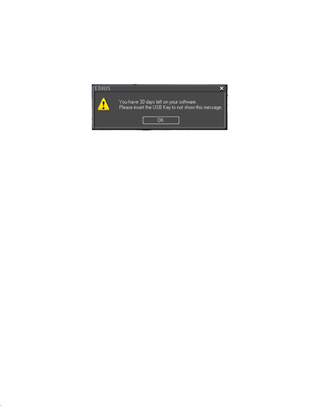
Section 1 — Getting Started
Startup Without USB Key License
The license for EDIUS is contained on the USB key that came in the box
with the product DVD. If EDIUS is started without the USB key inserted in
a USB port on the host computer, the message shown in
Figure 2. No USB Key Startup Message
Figure 2 appears.
Insert the USB key and click OK to detect the license and use EDIUS.
Note If OK is clicked without the USB key present, the 30-day trial countdown
period begins. If you wish to transfer the license from the USB key to the PC
or to another USB key, see License Transfer section below.
To avoid the message above, the USB key should be inserted before starting
EDIUS.
License Transfer
When EDIUS is installed on a laptop or, if you prefer not to use the USB key,
it may be desirable to transfer the license from the USB key to the laptop or
PC on which EDIUS is installed. It is also possible to transfer the license
from the USB key provided with EDIUS to another USB key. Before pro
ceeding with any license transfer, please thoroughly read the notes and
warnings which follow.
• The license transfer tool must be initiated on the system on which
• License transfer is available between USB key and PC or USB key and
• Several licenses of the same product cannot be combined on the same
WARNING A lost USB key cannot be replaced for any reason. Keep the USB key
-
EDIUS is already installed.
USB key only. It is not possible to transfer a license from PC to PC.
USB key.
secure and do not lose it.
WARNING Close the license transfer tool only after the transfer is complete. If the
transfer tool is closed prior to completing the transfer, the license is irretrievably lost.
24 EDIUS — User Reference Guide
Page 25
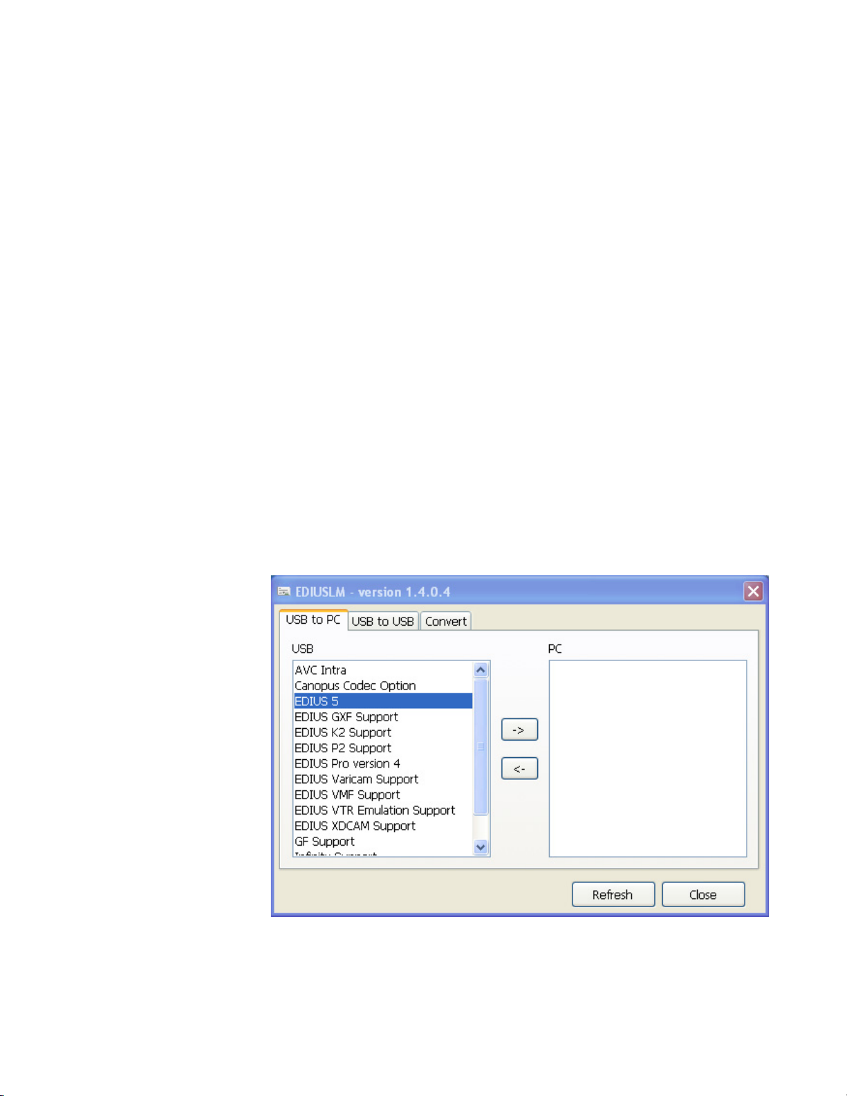
WARNING If the license is transferred to a PC and the hard drive on which the license
is stored becomes corrupted or fails with no backup, the license may be
irretrievably lost.
WARNING When a license is transferred to a PC, changing major PC components
such as CPU, memory, motherboard, hard drive, NIC, etc. may invalidate
the license.
A transfer of the license to a PC is not recommended without a compelling
reason for doing so.
Starting the License Transfer Tool
1. Attach the USB key to a USB port on the PC on which EDIUS is
installed.
2. Insert the installation DVD for the installed version of EDIUS into the
DVD drive.
3. Click on Browse DVD when the splash screen appears.
Starting EDIUS
4. Navigate to the Tools>EdiusLM folder and double click the file
EdiusLM.exe.
The screen shown in Figure 3 appears.
Figure 3. EDIUS License Manager Dialog Box
EDIUS — User Reference Guide 25
Page 26
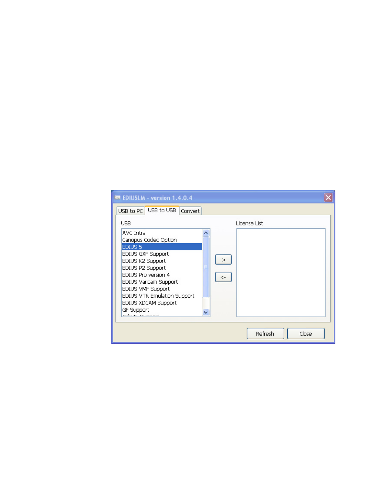
Section 1 — Getting Started
Transfer License to PC Local Disk
Transfer License to Another USB Key
1. Select the USB to PC tab in the dialog box.
2. Select the license to transfer from the list that appears in the USB to PC
tab.
3. Click the -> button to execute the license transfer.
4. Repeat for additional licenses to be transferred.
5. Click the Close button when all license transfers are complete.
1. Select the USB to USB tab in the dialog box. See Figure 4.
Figure 4. USB to USB License Manager Dialog Box
2. Select the license to transfer from the list that appears in the USB to USB
tab.
3. Click the -> button to move the license to the list on the right side of the
dialog box.
4. Replace the EDIUS USB key with the one to which the license should be
transferred.
5. Click the Refresh button.
26 EDIUS — User Reference Guide
Page 27
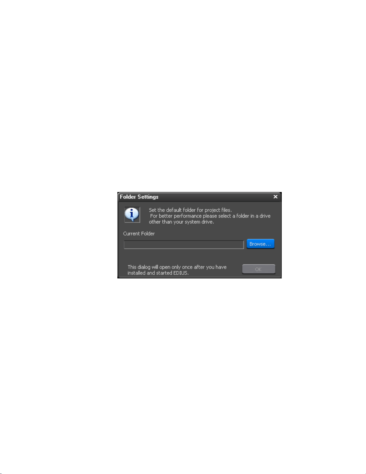
6. After the license transfer is complete, replace the destination USB key
with the original USB license key if you wish to transfer more licenses.
Note After every USB key swap, click the Refresh button.
7. Repeat the steps above to transfer additional licenses.
WARNING Do not replace USB keys while the license is transferring or the license
may be irretrievably lost.
8. Click the Close button when all license transfers are complete.
Select Project Folder Location
When EDIUS is started for the first time after a new installation (not an
upgrade from a prior version), the dialog box in
Figure 5. EDIUS Project Folder Location Dialog
Starting EDIUS
Figure 5 will appear.
To select a folder in which to store EDIUS projects, do the following:
1. Click the Browse button.
2. Navigate to the drive on which the desired folder is located or will be
created (see Figure 6).
EDIUS — User Reference Guide 27
Page 28
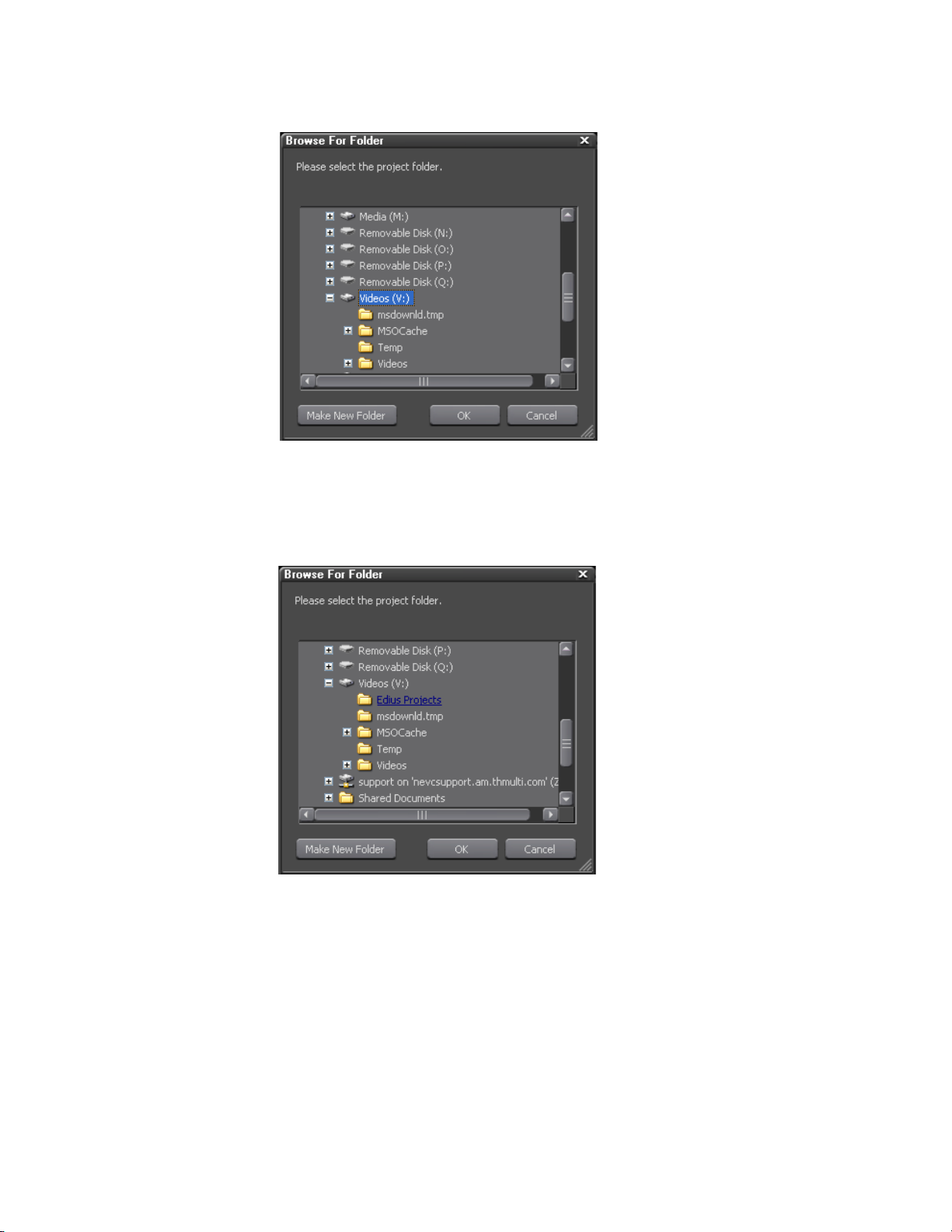
Section 1 — Getting Started
Figure 6. Browse to Project Folder Location
3. If the desired folder already exists on the selected drive, select the
desired folder and click the
OK button (see Figure 7).
Figure 7. Select Project Folder
4. If the desired folder does not exist on the selected drive, Click the Make
New Folder
button, enter the desired folder name and click on the OK
button (see Figure 8).
28 EDIUS — User Reference Guide
Page 29
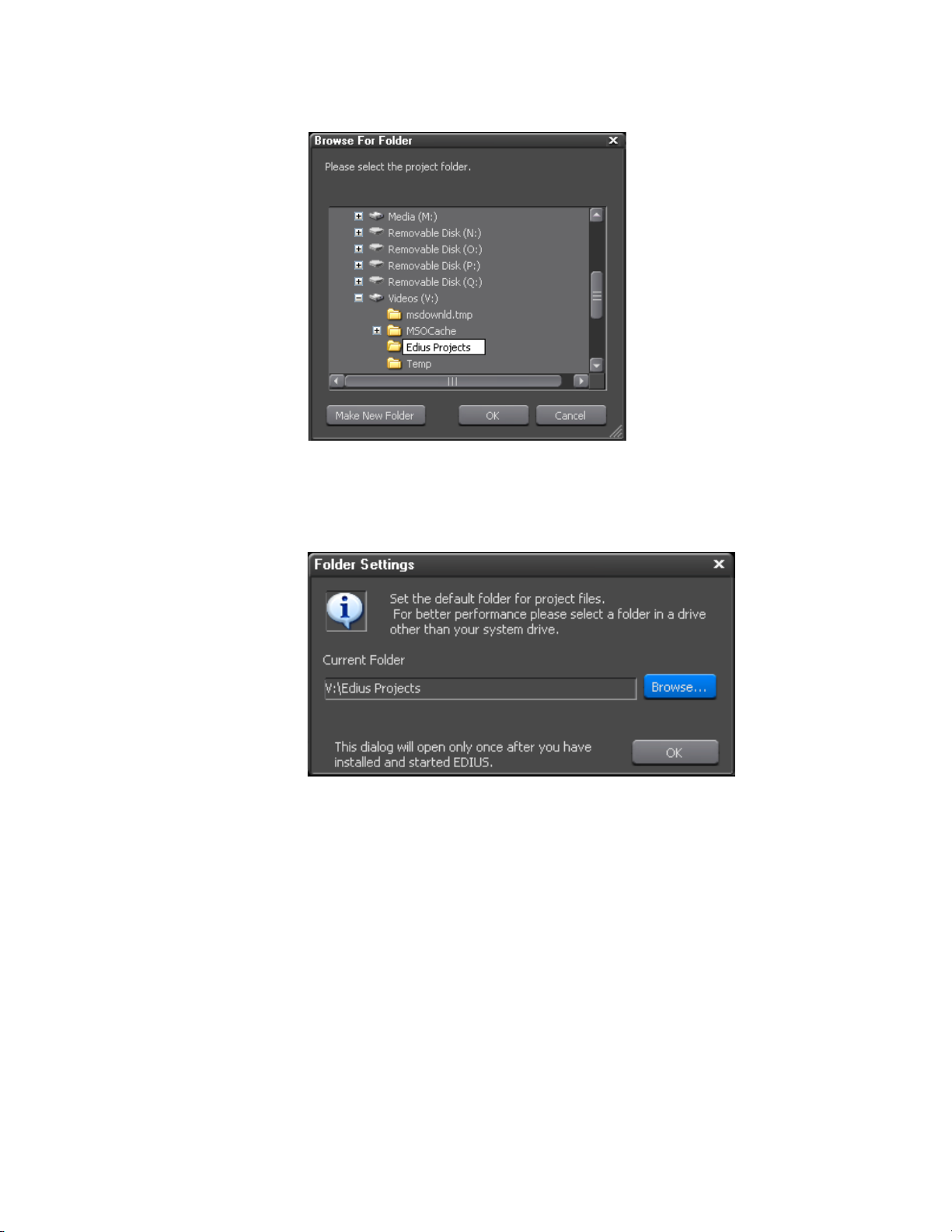
Entering Numeric Data
Figure 8. Make New Project Folder
The dialog box in Figure 9 appears indicating the selected project folder.
Figure 9. Project Folder Default Location
5. Click OK to set the current folder as the default folder for EDIUS project
files.
Note As indicated in the dialog box, once the default folder selection is made, this
dialog box will not appear again when EDIUS is launched.
Entering Numeric Data
Numeric data entry is possible or required in many application screens and
data input windows throughout EDIUS, including some startup screens.
This section explains the various methods of entering numeric data
EDIUS — User Reference Guide 29
Page 30

Section 1 — Getting Started
Direct Input
There are four methods for entering numeric data into an input field (examples of such data fields in Project Presets are the TC preset, Total length,
Over Scan Size, Audio Reference Level, Track(default), Duration, etc. The
four entry methods are:
• Direct Input
•Offset Input
•Arrow Key Input
• Mouse Wheel Input
Some input fields are time codes or duration which may be comprised of
multiple number segments. The format of these fields is HH:MM:SS;FF
(H=hour, M=Minutes, S=Seconds and F=Frames). Other numeric input
field are single-segment numbers such as the number of video and audio
tracks. Except where noted below, these numeric input methods apply to
all numeric fields.
The direct input method requires entering the numeric values from the keyboard. To enter a numeric value with the direct input method do the following:
1. Select the desired input field.
2. To enter, for example, the value 25 minutes, 16 seconds and 15 frames
3. Press the [Enter] key.
Note When entering a number such as 1 hour and 15 minutes with no seconds and
Offset Input
The offset input method is used to quickly increment or decrement an
existing timecode by a particular value.
Note Offset input is only available with timecode (multi-segment) values.
use one of the following methods:
a. enter 25M16S15F
b. enter 251615
frames, enter either 1H10M or 01150000. 10 minutes is entered as either
10M or 100000. 2 hours is entered as either 2H or 02000000.
To enter a timecode offset, follow these steps:
1. Select the desired input field.
30 EDIUS — User Reference Guide
Page 31

2. Enter the desired offset value.
A “+” before the value increments the timecode by the specified value.
A “-” before the value decrements the timecode by the specified value.
Note If the timecode value in a particular field is 00:05:35;20 (5 minutes, 35 sec-
3. Press the [Enter] key.
Arrow Key Input
With the arrow key input method, the arrow keys (K,L,I,J) are used to
enter or change numeric values.
To enter numbers using the arrow key input method, do the following:
1. Select the desired input field.
Entering Numeric Data
onds, 20 frames), entering an offset value of +2510 will increment the timecode value to 00:06:01;00 (assuming a 30 frame per second video standard).
Entering an offset value of -2510 will decrement the timecode to 00:05:10;10.
2. Use the [K] key to increment the numeric value; use the [L] key to
decrement the numeric value; use the [I] key to move one number
segment to the left; use the [J] key to move one number segment to the
right.
3. Press the [Enter] key when input is finished.
Mouse Wheel Input
The mouse wheel input method uses the mouse wheel or buttons to input
numeric data.
To enter numbers using the mouse, follow these steps:
1. Move the mouse cursor near the input field. The mouse cursor shape
changes to indicate that mouse wheel input mode is active.
2. Click the numeric value you wish to change whether it is part of a
multi-segment number or a single-segment value.
3. Rotate the mouse wheel up or down to increment or decrement the
selected value.
4. Press the [Enter] key when input is finished.
EDIUS — User Reference Guide 31
Page 32

Section 1 — Getting Started
An alternate mouse input method uses the mouse buttons as follows:
• Hold down the right mouse button and drag the mouse upwards from
the initial mouse position until the number begins to increase. Once the
number begins to increase, it will continue to increase until the mouse
button is released.
• Hold down the right mouse button and drag the mouse downward to
decrease the data value. Once the number begins to decrease, it will
continue to decrease until the mouse button is released.
Note The number will not decrement below a value of zero (0).
• Hold down the left mouse button and drag the mouse upward to
increase the value. Only continued upward movement of the mouse
will increase the data value.
• Hold down the left mouse button and drag the mouse downward to
decrease the value. Only continued downward movement of the mouse
will decrease the data value.
Note The number will not decrement below a value of zero (0).
Start-Up Window
Each time EDIUS is launched, the window shown in Figure 10 will appear.
When EDIUS is started for the first time after a new installation (not an
upgrade from a prior version), this window will be blank.
32 EDIUS — User Reference Guide
Page 33

Figure 10. EDIUS Start-up Window
Start-Up Window
Profiles
Create a Profile
The EDIUS start-up window is composed of three main areas; Profiles,
Recent Projects list and New Project presets.
Screen layouts, application settings, custom settings and plug-in settings
are associated with profiles. Each time a profile is selected for an EDIUS
session, the settings associated with that profile are automatically used.
Multiple profiles may be created.
Note Hardware settings, changes to the Effects palette and preset exporters are not
stored with profiles.
To create a profile, do the following:
1. Click on the New Profile button.
2. Enter a name for the profile.
3. If you wish to change the icon for this profile, click on the ... button.
4. Select the desired profile icon from the list (see Figure 11) and click the
Open button.
EDIUS — User Reference Guide 33
Page 34

Section 1 — Getting Started
Note There is no icon preview from the icon “Open” dialog box. See Table 1 below
for a list of default profile icons.
Figure 11. User Profile Creation
Table 1. User Profile Icons
Icon Name Icon Graphic
profile01
profile02
profile03
profile04
profile05
profile06
profile07
profile08
34 EDIUS — User Reference Guide
Page 35

Table 1. User Profile Icons
Icon Name Icon Graphic
profile09
profile10
profile11
profile12
profile13
profile14
profile15
Start-Up Window
Note If the table above is not viewed or printed in color, many icons will appear the
same. The difference between icons of the same design is the background
color.
5. Click the OK button to create the profile.
The EDIUS start-up screen re-appears
6. Create additional profiles as needed by repeating the steps above.
Change a Profile Name or Icon
To change the name or icon associated with a profile do one of the following:
• Select the profile and click the
as desired.
• Right-click on the profile icon select
menu.
Delete a Profile
To delete a profile do one of the following:
Change button. Change the name or icon
Rename or Change Icon from the
• Select the profile and click the Delete button.
• Select the profile and press the [Delete] key on the keyboard.
• Right-click the profile and select
Delete from the menu.
EDIUS — User Reference Guide 35
Page 36

Section 1 — Getting Started
Copy a Profile
To copy a profile do the following:
1. Right-click on the profile to be copied
2. Select Copy from the menu.
A new profile icon appears in the Profile list (see Figure 12 for an example).
Figure 12. Copied Profile
See Change a Profile Name or Icon above for information on changing the
profile name and icon.
Export Profiles
Profiles created in EDIUS on one computer can be exported and used in an
EDIUS system on a different computer. Profiles can be exported to network
drives, external drives, USB drives, etc. and then imported into the EDIUS
environment in which they are to be used.
To export one or all EDIUS profiles follow these steps:
1. Right-click on a profile icon.
2. Select Export from the menu.
36 EDIUS — User Reference Guide
Page 37

Start-Up Window
3. Select All or This profile from the export menu (see Figure 13).
Figure 13. Profile Export Menu
Note Just the right-clicked profile or all profiles may be exported. This profile
refers to the profile right-clicked in Step 1.
4. Navigate to the location in which the exported profile(s) will be stored
as shown in Figure 14.
Note A new folder may be created on the destination drive by clicking on the Make
New Folder button in the Browse For Folder dialog.
EDIUS — User Reference Guide 37
Page 38

Section 1 — Getting Started
Figure 14. Profile Export Location
5. Click the OK button the export the profile(s) to the selected location.
Import Profiles
Profiles that have been exported from an EDIUS system may be imported
into the same or another EDIUS system.
To import profiles, perform the following actions:
1. Right click on any profile icon.
2. Select Import from the menu.
3. Navigate to the location in which exported EDIUS profiles are stored
(an example is shown in Figure 15).
38 EDIUS — User Reference Guide
Page 39

Figure 15. Exported Profiles
Start-Up Window
4. Select the profile(s) to be imported.
Note To select multiple profiles, hold down the [CTRL] key while clicking on the
desired profiles. To select all profiles, click on the first profile in the list and
hold down the [SHIFT] key while clicking on the last profile in the list.
5. Click the Open button to import the selected profile(s).
If a profile with the same name as a profile to be imported already exists,
the dialog shown in Figure 16 appears.
Figure 16. Profile Overwrite Dialog
6. Select the appropriate response to continue importing profiles.
EDIUS — User Reference Guide 39
Page 40

Section 1 — Getting Started
Profile Management
Manage Profile Access
Profile management provides the ability to switch the active profile from
within EDIUS, change profile properties and configure access by EDIUS
workstations to shared profiles.
Note A dedicated profile management tool is installed on the server(s) on which
shared EDIUS profiles will be managed. The actions described in this section
pertain to EDIUS workstation settings and options and not the server-based
profile management operations.
To manage profile access do the following:
1. Select Settings>Change Profile from the Preview window menu bar as
illustrated in Figure 17.
Figure 17. Settings Change Profile Menu
The Change Profile dialog shown in Figure 18 appears.
Figure 18. Change Profile Dialog
40 EDIUS — User Reference Guide
Page 41

2. Click the Detail setting button.
The Detail Setting dialog illustrated in Figure 19 appears.
Figure 19. Profile Management Detail Setting Dialog
Start-Up Window
3. Select the profile location to be used from this EDIUS workstation by
selecting one of the following options:
Local
Only profiles stored on the local EDIUS workstation will be used.
Shared server
Only profiles stored in the shared server folder specified in the next step
will be used.
Local and shared server
Profiles stored in both the local EDIUS workstation and the shared server
location will be used.
EDIUS — User Reference Guide 41
Page 42

Section 1 — Getting Started
4. To use profiles stored in shared server, specify the folder containing
shared profiles by clicking the
... button and browsing to and selecting
the desired shared server folder.
Note If Local is the selected profile location, the Shared server options are not
available.
Note The Documents and Settings\{UserName\Application Data folder is not a valid
shared profile location on any computer.
5. If a Shared server location is specified, click the Sync button to
synchronize profiles stored on the local workstation with those stored
in the shared server location.
6. Select the desired profile and project preset change actions as described
below:
The Setting Change of the Profile is Permitted
If this option is selected, creating new profiles, changing profile settings
(name and icon) and profile deletion are permitted. If this option is not
selected, these actions are not allowed.
The Setting Change of the Project Preset is Permitted
If this option is selected, creating new project presets, changing project
preset settings (name and icon) and project preset deletion are permitted. If
this option is not selected, these actions are not allowed.
Switch Active Profile
To switch the active profile from with EDIUS, do the following:
1. Select Settings>Change Profile from the Preview window menu bar as
illustrated in Figure 20.
Figure 20. Settings Change Profile Menu
The Change Profile dialog shown in Figure 21 appears.
42 EDIUS — User Reference Guide
Page 43

Start-Up Window
Figure 21. Change Profile Dialog
The current profile is selected and listed in the Current profile field.
2. Select the profile you wish to activate.
Change, Delete and OK buttons will become active as illustrated in
The
Figure 22.
Figure 22. New Profile Selected
3. Click the OK button to activate the selected profile.
Change Profile Properties
To change a profile name or the icon associated with a profile, follow these
steps:
EDIUS — User Reference Guide 43
Page 44

Section 1 — Getting Started
Note This action is available only if the “Setting change of the profile is permitted”
option is selected. See Manage Profile Access on page 40 for more information.
1. Select Settings>Change Profile from the Preview window menu bar.
The Change Profile dialog appears.
2. From the Change Profile dialog, select the desired profile
3. Click the Change button.
The new preset dialog shown in Figure 23 appears.
Figure 23. New Preset Dialog
4. Enter a new profile name, if desired.
5. Click the ... button and browse to the icon file you wish to assign to the
selected profile.
6. Click the OK button to close the New Preset dialog.
44 EDIUS — User Reference Guide
Page 45

Project Presets
Project presets make it possible to start a new project with predetermined
default settings. Settings which can be defined in project presets include the
following:
• Output Device
•Output Format
• Rendering Format
• Time Code Preset and Mode
• Total Length
•Overscan Size
•Audio Reference Level
• Panning Mode
• Color Space Conversion
• Number of Video and Audio Tracks
Start-Up Window
• Audio Channel Map
Multiple project presets may be created from which the appropriate selection is made when a new project is started.
Create a Project Preset
To create a project preset, do the following:
1. From the start-up window, click the New Preset button. The dialog box in
Figure 24 appears.
EDIUS — User Reference Guide 45
Page 46

Section 1 — Getting Started
Figure 24. Project Preset Settings
2. From the list of available output devices, select the output device for the
project preset.
3. From the list of output formats, select the default output format for the
project preset
Note The Description section of the Project Settings dialog will contain details such
as frame size, frame rate, audio rate, sample size, channels, etc. based on the
output device an output format selections.
4. In the Setup(default) section of the dialog box, click on the list button
[V] of the
Rendering format button. A drop-down list similar to the one
shown in Figure 25 appears. Select the desired rendering format.
46 EDIUS — User Reference Guide
Page 47

Start-Up Window
Figure 25. Rendering Format Drop-Down List
Note The list of available rendering formats may change depending upon the
selected output device and output format. See Appendix A-Hardware Settings
for more information on output device and rendering codecs.
5. Click the Detail button to see rendering codec details. See Figure 26.
Figure 26. Rendering Codec Settings
Change settings as desired.
EDIUS — User Reference Guide 47
Page 48

Section 1 — Getting Started
6. Set the TC preset as desired. The TC preset will be the starting timecode
on the Timeline for any project using this project preset. See Starting
EDIUS on page 23 for the various methods of entering numeric data and
timecodes.
7. Select the TC mode by clicking on the list button [V] on the TC mode
button. If an NTSC device was selected in Step 2 above, you may select
“drop frame” or “non drop frame” for the timecode display.
8. If desired, you can set the desired length of the Timeline by entering a
value in this field. If a value is entered, the Timeline length is fixed to
this time. When the project exceeds this length, the color of the Timeline
section that exceeds this length is changed.
9. If over scanning is desired, enter the desired overscan ratio in the Over
Scan Size field. The value can be set from 0% to 20%. Setting the value
to 0 results in no overscan.
10. Enter the desired audio reference level. Clicking on the list button [V]
Audio Reference Level button displays a drop-down list of common
of the
reference levels (-20 dB, -18dB and -12dB); however, any reference level
may be entered.
Note In any field with a drop-down selection list (indicated by the Vsymbol next
to the field), the [K] and [L] keys may be used to scroll through the list
choices without opening the drop-down list.
11. Select the desired Panning mode. The choices are ‘Standard” and
“EDIUS Pro3 Compatible.” This setting affects the appearance of the
audio rubber band for audio channels defined as “Monaural channel.”
Use “EDIUS Pro3 Compatible” only if you have been using this version
for past projects.
12. Set Color Space Conversion as desired. “Standard” detects the
appropriate color space in different formats automatically and converts
to the appropriate color space. Set to “EDIUS Pro3 Compatible” to use
the original color space of each source even when multiple formats are
used in the project.
13. In the Track(default) section of the Preset Settings dialog specify the
desired number of default video, audio and title tracks.
• V = video tracks
• VA = video/audio tracks (video with separate but connected audio)
• T = Title tracks
• A = Audio tracks
14. Click on the Channel Map button to display the Audio channel map
dialog as shown in Figure 27.
48 EDIUS — User Reference Guide
Page 49

Figure 27. Audio Channel Map
Start-Up Window
15. Select the desired output channels for each track. Click the OK button
when finished.
Note Two (2) channels maximum can be output from one track. The number and
types of tracks displayed may vary depending on the Track settings specified
in Step 13.
16. Click the OK button to close the Project Settings dialog box.
The project preset name dialog shown in Figure 28 appears.
Figure 28. Project Preset Name
17. If you wish to accept the default project preset name and icon, proceed
to Step 21.
18. If you wish to change the name, enter a new name.
EDIUS — User Reference Guide 49
Page 50

Section 1 — Getting Started
19. If you wish to select an icon other than the default icon, click the ...
button. The icon list shown in Figure 29 appears.
Figure 29. Project Preset Icon List
20. Select the desired icon from the list and click the Open button.
21. Click the OK button to accept the project preset name and icon.
The EDIUS start-up screen re-appears (see Figure 30) with the new preset
definition in the New Project window.
50 EDIUS — User Reference Guide
Page 51

Figure 30. EDIUS Start-up Screen with New Project Definition
Start-Up Window
22. Create additional project presets as needed by repeating the steps
above.
Create a New Project
EDIUS projects can be created from project presets or from the current
project.
Create a New Project from a Project Preset on Startup
Before selecting the project preset, make sure you have clicked on the
desired profile in the Profile area of the start-up screen. The selected profile
icon and name appear in the Selected Profile area in the upper right corner
of the start-up screen (see
when a new project is initiated.
To create a new project using a project preset, do the following:
1. Double-click the desired project preset icon in the New Project area of
the EDIUS start-up screen.
Note You may also single-click to select the desired preset icon and then click the
Figure 30). This selected profile will be used
Start button in the lower right corner of the start-up screen.
The Project name setting dialog shown in Figure 31 appears.
EDIUS — User Reference Guide 51
Page 52

Section 1 — Getting Started
2. Enter the project name in the Project name field.
Figure 31. New Project Preset Name
Note The default project folder is the folder specified in Select Project Folder Loca-
tion on page 27.
3. Select the “Create project name folder” to create a folder with the same
name as the project in the selected project folder. The project file(s) will
be stored in this folder.
Note If the “Create project name folder” option is not selected, the project file(s)
will be stored in the selected folder location without creating a new folder with
the project name.
If you wish to specify a location for this project other than the default, click
... button and browse to the desired location. Click to OK button to select
the
the new folder.
4. Click OK to create the new project and open EDIUS.
A blank project (no data in the Timeline, Recorder/Player, or Asset Bin
widows) appears as illustrated in Figure 32.
52 EDIUS — User Reference Guide
Page 53

Figure 32. EDIUS New Project
Start-Up Window
Create a New Project From the Current Project
A new project can be created from the current project in one of three ways.
• Select File>New>Project from the Preview Window
• Click the list button [V]on the
from the menu. See Figure 33.
Figure 33. Create New Project from New Sequence List Button
Note Clicking the New Sequence button, will result in the creation of a new
sequence in the current project. To create a new project, click on the list
button
[V] symbol. See Sequences on page 58 for more information on
sequences.
• Press [CTRL]+[N] on the keyboard
New Sequence Icon and select New Project
EDIUS — User Reference Guide 53
Page 54

Section 1 — Getting Started
To create a new project from the current project, do the following:
1. Perform any of the three actions listed above to initiate the creation of a
new project.
After performing any of these actions, a dialog prompting to save the
current project file appears. See Figure 34.
Figure 34. Save Current Project Dialog
2. Click Yes to save the current project.
The Project settings (simple settings) dialog box shown in Figure 35
appears.
Figure 35. Project Settings (Simple Settings) Dialog
3. Enter a name for the project in the Project name field.
4. Select the desired project preset and click the OK button.
Note If you wish to create a new project preset, click the New Preset button and
follow the instructions to Create a Project Preset on page 45.
54 EDIUS — User Reference Guide
Page 55

Change Current Project Settings
Although a project is started with a project preset and its associated settings, it is possible to change the settings for a particular project at any time
before project output.
To change project settings, do the following:
1. Select Settings>Project Settings from the Preview window
The Project Settings window shown in Figure 36 appears.
Figure 36. Project Settings - Change Current Settings
Start-Up Window
2. Click the Change current setting... button.
The Project Settings detail window appears. See Figure 37
EDIUS — User Reference Guide 55
Page 56

Section 1 — Getting Started
Figure 37. Project Settings Detail
3. Change the desired project settings. See Create a Project Preset on page 45
for details concerning project settings.
4. Click the OK button to save the changes to the current project settings.
If you back into Settings>Project Settings you will notice the addition of the
Current Setting icon (see Figure 38). The current project settings are associated with this project preset.
Note Changing the current project settings does not change the settings associ-
ated with the original preset from which the project was initiated.
Figure 38. Project Settings - Current Settings
56 EDIUS — User Reference Guide
Page 57

Save the Current Settings as a New Project Preset
If you wish to create a new preset from the current settings, perform the following actions:
1. Click on the Current setting icon.
2. Click the New Preset button.
Note The Current setting preset cannot be deleted or changed (buttons are greyed
out). If you wish to change the current settings use the Change current setting... button.
3. Click the OK button to save the current settings.
Note Do not make any setting changes if you wish to save the current settings as
a new project preset.
4. (Optional) Enter a name and select an icon for the new project preset.
5. Click the OK button to save the project preset.
Start-Up Window
Change the Settings of an Existing Project Preset
If you wish to make changes to the settings of an existing project preset, do
one of the following:
• Click on the project preset icon from either the EDIUS start-up window
or the Project Settings dialog shown in Figure 36 and click the
button.
• Right-click the preset icon for which you wish to change the settings
and select
Change preset from the menu.
Other Actions in the Simple Settings Dialog
The following actions can be performed from the Project Settings (Simple
Settings) dialog box shown above in
• Specify a folder other than the default for a project location. Click the ...
button to navigate to another folder.
• Delete existing project presets. Click on the project preset icon; click the
Delete button to delete the project preset.
Note An alternative method of deleting project presets is to right-click on the
project preset icon and select the Delete option from the menu.
Figure 35:
Change
EDIUS — User Reference Guide 57
Page 58

Section 1 — Getting Started
Sequences
Create a New Sequence
A sequence is a collection of clips, images, effects, etc. placed on the Timeline. A project may be comprised of one or more sequences.
The sequence tab is located in the upper left corner of the Timeline window
just above the Timeline and just below the project name (see Figure 39).
Figure 39. Sequence Tab
To create a new sequence in the current project, do one of the following:
• Click the New Sequence button in the Timeline window (see Figure 40 -
New Sequence button is highlighted in blue).
the
Figure 40. New Sequence Button
• Select File>New>Sequence from the Preview window menu bar.
• Right-click on a blank area of the clip view in the Asset Bin and select
“New Sequence” from the menu.
Note In this case a blank Timeline sequence clip is created in the Asset bin but a
sequence tab is not displayed in the Timeline window.
•Press [SHIFT]+[CTRL]+[N] on the keyboard.
Any of these methods will result in a new sequence tab appearing in the
Timeline window as shown in Figure 41 as well as the creation of a
sequence clip in the Asset bin as illustrated in Figure 42.
58 EDIUS — User Reference Guide
Page 59

Figure 41. New Sequence Tab
Note Double right-click a sequence tab to change the sequence name.
Figure 42. New Sequence Clip In Asset Bin
Sequences
Note The sequence tabs can be dragged and dropped to change their order.
Sequence Settings
Some sequence settings may have been defined when creating project presets. The Sequence Settings dialog is illustrated in Figure 43.
Figure 43. Sequence Settings Dialog
EDIUS — User Reference Guide 59
Page 60

Section 1 — Getting Started
To change sequence settings, access the Sequence Settings dialog in one of
the following ways:
• Click on the list button [V] of the Save Project icon (see Figure 44) in the
Timeline window and select
Figure 44. Save Project Menu
Sequence Settings... from the menu.
• Select Settings>Sequence Settings from the Preview window.
• Right-click on a sequence tab in the Timeline window and select
Sequence Settings... from the menu.
• Right-click a sequence clip in the Asset Bin and select
Sequence Settings...
from the menu.
The settings that can be changed in the Sequence Settings dialog are:
•Tc Preset — The TC preset will be the starting timecode on the Timeline
for any project using this project preset. See Starting EDIUS on page 23
for the various methods of entering numeric data and timecodes.
•Tc Mode — Select the TC mode by clicking on the V symbol on the TC
mode button. If an NTSC device was selected in Step 2 above, you may
select “drop frame” or “non drop frame” for the timecode display.
•Total length — If desired, you can set the desired length of the Timeline
by entering a value in this field. If a value is entered, the Timeline length
is fixed to this time. When the project exceeds this length, the color of
the Timeline section that exceeds this length is changed.
• Panning mode — The choices are ‘Standard” and “EDIUS Pro3 Compatible.” This setting affects the appearance of the audio rubber band
for audio channels defined as “Monaural channel.” Use “EDIUS Pro3
Compatible” only if you have been using this version for past projects.
60 EDIUS — User Reference Guide
Page 61

Saving Projects
• Color Space Conversion — “Standard” detects the appropriate color
space in different formats automatically and converts to the appropriate color space. Set to “EDIUS Pro3 Compatible” to use the original
color space of each source even when multiple formats are used in the
project.
• Channel Map — Click on the
channel map dialog as shown in Figure 27.
Figure 45. Audio Channel Map
Channel Map button to display the Audio
Select the desired output channels for each track. Click the OK button
when finished.
Note Two (2) channels maximum can be output from one track. The number and
types of tracks displayed may vary depending on track settings.
In the Sequence Settings dialog, make the desired changes to the sequence
settings and click the
OK button to save the changes and close the dialog.
Saving Projects
EDIUS projects are saved as .ezp files in the folder specified as the projects
folder. See
EDIUS — User Reference Guide 61
Select Project Folder Location on page 27 for more information.
Page 62

Section 1 — Getting Started
To save a project with the name entered (or the default name) at project creation, do one of the following:
• Click the
Save project button (highlighted in blue in Figure 46) in the
Timeline window.
Figure 46. Timeline Save Project Button
• Click on the list button [V] of the Save project button and select “Save
Project” from the menu.
• Select File>Save Project from the preview window menu bar.
• Press the [
Note As illustrated in Figure 46, the current project name which will be used for
CTRL]+[S] keys on the keyboard.
saving the file with the methods listed above is shown in the Timeline
window.
To save a project with a name other than the current name, do one of the
following:
• Click on the list button [V] of the
• While holding down the [
• Select File> Save As from the preview window menu bar.
• Press the {
Note Using any of the methods described above will display a Save As dialog in
Auto Save/Backup
Backup files are only used in unusual circumstances such as project files
becoming corrupted or EDIUS crashing while editing. They are not used in
normal operations.
Backup files are created automatically in the following manner:
Save project button and select “Save
As” from the menu.
SHIFT] key, click the Save project button (high-
lighted in blue in Figure 46) in the Timeline window.
SHIFT]+[CTRL]+[S] keys on the keyboard.
which you can choose a location and file name in which to save the project.
62 EDIUS — User Reference Guide
Page 63

Exiting EDIUS
Location
{Project Name}/{Project}/Backup
File Name
{Project name}-year, month, day - hour, minute, second.ezp
If the auto save is enabled, project files are automatically saved at the specified interval. For information on enabling auto save see Enable Auto Save/
Auto Save Interval on page 153.
When auto save is enabled, auto save files are created in the following
manner:
Location
{Project Name}/{Project}/AutoSave
File Name
{Project name}-year, month, day - hour, minute, second.ezp
To recover a project from an auto save or backup file, copy the file to the
original project folder and import the file.
Note Auto save and backup files are read only and cannot be overwritten.
Exiting EDIUS
To exit EDIUS, do any of the following:
• Select File>Exit from the Preview window menu bar (see Preview
• Press the [
• Click on the “X” in the upper right corner of the preview window.
Project Operations
Window on page 109 for more information) and click on the
you wish to exit EDIUS or the
operation.
ALT]+[F4] keys on the keyboard.
No button if you wish to cancel the exit
Yes button if
This section covers project operations such as opening, importing and
exporting project information.
EDIUS — User Reference Guide 63
Page 64

Section 1 — Getting Started
Opening Project Files
Open Project on Startup
Projects may be opened on EDIUS startup or within EDIUS from the
current project.
To open a project on startup, do one of the following when the startup
screen illustrated in Figure 47 appears:
• Double-click the desired project icon in the Recent Project list.
• Click the desired project icon in the Recent Project list and click the
Project
button.
• Click the desired project icon in the Recent Project list and click the
button.
Note Projects may be removed from the Recent Project list by selecting the project
to be removed and clicking the Clear History button.
Figure 47. EDIUS Startup Screen Project Icons
Open
Start
64 EDIUS — User Reference Guide
Page 65

Open a Project from the Current Project
To open a different project from within the current project, do any of the following:
• Click the Open Project button (highlighted in blue in Figure 48) in the
Timeline window and select the project to open from the Open dialog.
Figure 48. Timeline Open Project Button
• Click the list button [V] of the Open Project button and select the desired
project from the history of recently opened projects at bottom of the
menu.
• Select File>Recent Project>{project name} from the preview window
menu bar.
Project Operations
• Select File>Open Project from the preview window menu bar and select
the desired project from the Open dialog.
• Press the [
Importing Sequences
A collection of clips, images, effects, etc. placed on the Timeline is known
as a “sequence.”
Sequences created in another project may be imported into the current
project. The imported project will appear as a new sequence in the current
project.
To import a sequence, do the following:
1. Click the list button [V] of the Open Project button and select “Import
Sequence” from the menu as illustrated in Figure 49.
Note An alternative method is to select File>Import Sequence from the preview
CTRL]+[O] keys on the keyboard.
window menu bar.
EDIUS — User Reference Guide 65
Page 66

Section 1 — Getting Started
Figure 49. Open Project Button Menu - Import Sequence
The Import Sequence dialog shown in Figure 50 appears.
Figure 50. Import Sequence Dialog
2. Select the desired import settings as explained below:
66 EDIUS — User Reference Guide
Page 67

Project Operations
Import Project
Use the list button [V] to select a project from the history of recently
opened projects or the
dialog. When a project is selected, project details are displayed (see
Figure 50 above).
If the frame size or aspect ratio of the selected project is different than
current project, these are displayed in red as shown in Figure 50.
Attempting to import the project when these settings do not match will
result in the warning illustrated in Figure 51.
Figure 51. Sequence Import Settings Mismatch Warning
Browse button to select the project from an Open
Note If the frame rates are different, the projects cannot be combined.
Import Bin
The contents of the merged projects can be placed in a designated folder in
the Asset Bin. Select the “Import Bin” option and enter the name of the
folder you want to create as the import location. This folder will be created
under the “root” folder as illustrated in
Figure 52. Asset Bin Import/Merge Folder Created
Figure 52
Copy Files
Select the “Copy clips in project folder” option to copy the files used in a
merged project.
Note Copy files is not available when the project folder is the same as the folder for
the project to be merged.
Select the “copy rendered files” option if you wish to copy the rendered
files as well.
EDIUS — User Reference Guide 67
Page 68

Section 1 — Getting Started
Consolidate Project
Note Rendered files cannot be copied if the project to be imported has a frame size,
aspect ratio or overscan size that differs from the current project.
Enter the desired folder name to which the files should be copied. This
folder will be created under the current project folder.
3. Click the OK button, to import the project/sequence using the
designated import settings.
Project consolidation removes unused clips or portions of clips from the
project folder. Consolidation is also useful in creating a smaller copy of the
project file to, for example, transfer the project to removable media for
archival.
Note See File Formats Supported In Trimming Operations on page 770 of
Appendix C-Input/Output Formats for more information on file format
support in trimming and consolidation operations.
To consolidate a project, do the following:
1. Click the list button [V] of the Save Project button and select
“Consolidate Project” from the menu as illustrated in Figure 53.
Note An alternative method is to select File>Consolidate Project from the preview
window menu bar.
Figure 53. Timeline Save Project Menu - Consolidate Project
Note If the message “Not enough disk space for consolidating” appears, change
the project saving destination to a drive with more available space.
The Consolidate Project dialog appears as shown in Figure 54
68 EDIUS — User Reference Guide
Page 69

Figure 54. Consolidate Project Dialog
Project Operations
2. Select the desired consolidation settings according to the following
explanations:
Project File Location
Select the location to which to save the consolidated project.
Current Project Location
If this location is selected, the current project files are overwritten with
the consolidated project files
Save Project to Folder
Designate a new folder location to which to save the consolidated
project files. If this option is selected, enter or browse to the folder loca
tion to which to save the files.
EDIUS — User Reference Guide 69
-
Page 70

Section 1 — Getting Started
Note When a project folder is selected, the available drive space and required drive
space for the consolidated files is displayed. If the required space exceeds the
available space, the required space is displayed in red.
Settings
From the “Consolidate option” drop-down list, select the desired consolidation method. Consolidation method details are displayed in the “Detail”
window as each option is selected.
Cleanup
This will clean up the hard disk drive. Files that are not used in the
project will be deleted. Once you delete the files, they will be perma
nently erased from the hard disk drive.
Backup
This will backup the project together with all files in the Asset bin. All
files in the Asset bin will be copied. Files in the Timeline but not in the
Asset bin will be trimmed (only the used area of the files are copied)
and copied to the project folder.
-
A trim margin can be set for this option. The allowable trim margin
range is from 00:00:00;00 to 00:01:00;00. The trim margin is the area
between clips that can be used for adding transitions and audio cross
fades or for “fine-tuning” the clip trimming.
Backup (no trimming)
This will backup the entire project. All the files that are used in the
project will be copied in to the project folder (files that are already in the
project folder will not be copied again).
Backup and Cleanup
This will backup the project with trimming and also clean up the hard
disk drive. Files that are used in the project will be trimmed (only the
used area of the files are copied) and copied to the project folder. Files
that are not used in the project will be deleted. This operation will allow
you to save disk space, but the deleted files can not be recovered.
A trim margin can be set for this option. The allowable trim margin
range is from 00:00:00;00 to 00:01:00;00. The trim margin is the area
between clips that can be used for adding transitions and audio cross
fades or for “fine-tuning” the clip trimming.
Backup and Cleanup (no trimming)
This will backup the project and clean up the hard disk drive. Files that
are used in the project will be copied in their entirety without trimming.
Files that are not used in the project will be deleted.
70 EDIUS — User Reference Guide
Page 71

Project Operations
Custom
If “Custom” is selected, the following options are available:
• Remove unused clips in Timeline - removes clips from the Asset Bin
that are not used in the Timeline.
• Leave only areas used in the Timeline - saves as another file the clip
areas in the Timeline that are used in the project. These new file(s)
then replace(s) the file(s) currently on the Timeline.
Note This option is available for AVI files only. The new file(s) are saved in a folder
created in the project folder.
• Copy used files to Project Folder - copies all the clips used in the
project to the designated project folder.
• Delete unused files in Project - Delete all unused clips from the
project folder.
Note This option is available only when one of the other custom options is
selected. Even if the delete unused files option is selected, files may not be
deleted if user access rights to the project folder do not allow delete operations.
Proxy Clip
If a proxy clip is used, select the proxy data type from the drop-down list.
Output Log
Select the this option and enter or browse to the location in which to save a
log file containing the details of the consolidation operation.
3. Click the OK button to consolidate the project according to the selected
Note If the “Delete unused files in Project” option was selected, a confirmation
Import AAF Files
Advanced Authoring Format (AAF) is a multimedia file format that allows
the exchange of digital media and metadata between platforms, systems,
and applications. Authoring applications that support AAF (such as
EDIUS, Avid Xpress and others) read and write data in AAF files to the
extent that they support the format. AAF is a widely-recognized file
exchange standard for video editing.
settings.
message is displayed. Click the Yes button to continue.
EDIUS — User Reference Guide 71
Page 72

Section 1 — Getting Started
AAF files imported into EDIUS have the following limitations:
• The output in the AAF file must be frame based
• Embedded AAF files are not supported - the AAF file must reference
the source files directly.
To import an AAF file, do the following:
1. Click the list button [V] of the Open Project button and select “Import
Project>AAF” from the menu as illustrated in Figure 55.
Note An alternative method is to select File>Import Project>AAF from the preview
window menu bar.
Figure 55. Timeline Open Project Menu - Import Project AAF
The Open dialog illustrated in Figure 56 appears.
72 EDIUS — User Reference Guide
Page 73

Figure 56. AAF File Open Dialog
Project Operations
2. Select the AAF file to import from the Open dialog
3. Click the Open button to import the AAF file.
Note When importing an AAF file, if the “New sequence” option is selected in the
Import EDL Files
An Edit Decision List (EDL) is a way of representing sequences of clips or
reels stored on disk. It contains an ordered list of file and timecode data
which represents the final edit.
To import an EDL file, follow these steps:
1. Click the list button [V] of the Open Project button and select “Import
Open dialog, a new sequence in the current project is created to which the
AAF file is imported. If this option is not selected, a new track in the current
sequence is created to which the AAF file is imported.
Project>EDL” from the menu as illustrated in Figure 57.
EDIUS — User Reference Guide 73
Page 74

Section 1 — Getting Started
Note An alternative method is to select File>Import Project>EDL from the preview
window menu bar.
Figure 57. Timeline Open Project Menu - Import Project EDL
The Open dialog illustrated in Figure 58 appears.
Figure 58. EDL File Open Dialog
74 EDIUS — User Reference Guide
Page 75

Project Operations
Note When importing an EDL file, if the “New sequence” option is selected in the
Open dialog, a new sequence in the current project is created to which the
EDL file is imported. If this option is not selected, a new track in the current
sequence is created to which the EDL file is imported.
2. Click the Detailed Settings button in the lower left corner of the Open
dialog.
The EDL Importer Settings Dialog shown in Figure 59 appears.
Figure 59. EDL Importer Settings Dialog
3. Select the desired EDL import settings as explained below:
EDIUS — User Reference Guide 75
Page 76

Section 1 — Getting Started
EDL Type
Select the EDL file type of the file to be imported from the drop-down list.
Choices are:
• BVE5000
• BVE9100
•CMX340
• CMX3600
If a CMX type is selected, the mode for calculating the Out point of a file
with a specified playback speed is available for selection.
Mode 1
Calculates the Out point timecode by adding the source duration multiplied by playback speed (also know as Dynamic Motion Control or
DMC) to the Player In timecode.
Note If the speed is a negative value, source duration multiplied by playback speed
is subtracted from the Player In timecode.
Mode 2
Use the Player Out timecode. Do not calculate an Out timecode. The
Player In an Out timecodes become the source In and Out points.
Handle Black Clips as Empty Clips
If this option is selected, reel names of BL, BLK or BLACK designate black
clips which will be handled as empty clips.
Overwrite Clips that are Stacked on Top of Each Other in the Timeline Video
Track
If this option is selected and “New Sequence” is not selected in the Open
dialog, the current clips that are on stacked the 1VA (or 1V) track on the
Timeline will be overwritten.
If this option is not selected and “New Sequence” is not selected in the
Open dialog, stacked clips will be placed on the 2VA, 3VA, etc. (or 2V, 3V,
etc.) tracks. If the tracks do not exist, they will be created.
Overwrite Audio Clips that are Stacked on Top of Each Other in the Timeline
Audio Track
If this option is selected and “New Sequence” is not selected in the Open
dialog, the current clips that are on stacked the 1VA (or 1A) track on the
Timeline will be overwritten.
If this option is not selected and “New Sequence” is not selected in the
Open dialog, stacked clips will be placed on the 2VA, 3VA, etc. (or 2A, 3A,
etc.) tracks. If the tracks do not exist, they will be created.
76 EDIUS — User Reference Guide
Page 77

Project Operations
Match Channels When the Channels in a Transition’s “From” Side and
“To” Side Are Different
This setting is available if a CMX file type is selected.
Export Error Log
If selected, this setting will export the log to a file when import errors
occurs. Select the desired Export Format and Export type. If the Export
Type is set to “All” the imported contents as well as the errors are specified
in the log.
4. Click to OK button to set the selected import settings.
The EDL Importer Detailed Settings dialog closes and control is returned to
the Open dialog.
5. Click the Open button to import the EDL file using the selected import
settings.
The EDL file is imported and the Find Offline Clip dialog appears. Restore
the offline clip(s) using the methods explained in Restore Offline Clips on
page 96.
Important Considerations
The following limitations exist when importing the indicted EDL file types:
BVE5000/BVE9100
• Edit Modes ASMBL and ASSY1 are not supported
• Edit Types C, W and D are the only types supported
• GPI Data Line is not supported
• Learn Data Line is not supported
CMX340/CMX3600
• Edit Types C, W and D are the only types supported
Import Final Cut Pro (FCP) XML Files
To import a Final Cut Pro XML file do the following:
1. Click the list button [V] of the Open Project button and select “Import
Project>FCP XML” from the menu as illustrated in Figure 60.
Note An alternative method is to select File>Import Project>FCP XML from the
preview window menu bar.
EDIUS — User Reference Guide 77
Page 78

Section 1 — Getting Started
Figure 60. Timeline Open Project Menu - Import Project FCP XML
The Open dialog illustrated in Figure 61 appears.
Figure 61. Final Cut Pro XML Open Dialog
2. Select the Final Cut Pro XML file to import from the Open dialog
3. Click the Open button to open the selected Final Cut Pro XML file.
78 EDIUS — User Reference Guide
Page 79

Project Operations
The project described in the Final Cut Pro XML file will be imported as a
new EDIUS sequence.
Note If any errors occur during the import process, an error log with the name
“{XML file name}+ErrorLog.csv will be created in the same location as the
FCP XML file. An error dialog will appear with this information.
Special Considerations
• The following items are supported when importing a Final Cut Pro
XML file:
• Video, audio and still clips
• Transitions
Note All Final Cut Pro transitions will be replaced by EDIUS dissolve transitions
• Sequence clip
Note When a sequence clip is used in several places on the Timeline each instance
will be recognized as separate clips. This is the same behavior as Final Cut
Pro.
•Freeze frame
• Multiclip
• Clips generates wit Bars and Tone and Color Matte in the Video
Generator folder.
• A clip generated in the formats listed below using the Bars and Tone
video generator in Final Cut Pro will be imported as a color bar clip in
the EDIUS Timeline:
• Bars and Tone (HD 1080i60)
• Bars and Tone (HD 25p/50i Full Frame)
• Bars and Tone (HD 25p/50i)
• Bars and Tone (HD 720p60)
• Bars and Tone (NTSC
• Bars and Tone (PAL Full Frame)
• Bars and Tone (PAL)
• More bars and Signals
• A clip generated using Final Cut Pro Color or Slug will be imported as
a black color matte clip in the EDIUS Timeline
• When importing a Final Cut Pro multiclip, all clips included in the multiclip will be placed on the EDIUS Timeline
EDIUS — User Reference Guide 79
Page 80

Section 1 — Getting Started
Import P2 Playlists
• The following item types are not supported when importing a Final Cut
Pro XML file:
• Clips which cannot be handled as offline clips
• Title (text) clips
•Key frames
• Video filters
To import a P2 Playlist file, follow these steps:
1. Click the list button [V] of the Open Project button and select “Import
Project>P2 Playlist” from the menu as illustrated in Figure 62.
Note An alternative method is to select File>Import Project>P2 Playlist from the
preview window menu bar.
Figure 62. Timeline Open Project Menu - Import Project P2 Playlist
The Open dialog illustrated in Figure 63 appears.
80 EDIUS — User Reference Guide
Page 81

Figure 63. P2 Playlist Open Dialog
Project Operations
2. Select the P2 Playlist to import from the Open dialog
3. Click the Open button to import the P2 Playlist.
Note When importing a P2 Playlist, if the “New sequence” option is selected in the
Import XDCAM Files
To import a XDCAM file, follow these steps:
1. Click the list button [V] of the Open Project button and select “Import
Project>XDCAM” from the menu as illustrated in Figure 64.
Note An alternative method is to select File>Import Project>XDCAM from the
Open dialog, a new sequence in the current project is created to which the P2
Playlist is imported. If this option is not selected, a new track in the current
sequence is created to which the P2 Playlist is imported.
preview window menu bar.
EDIUS — User Reference Guide 81
Page 82

Section 1 — Getting Started
Figure 64. Timeline Open Project Menu - Import Project XDCAM
The Open dialog illustrated in Figure 65 appears.
Figure 65. XDCAM File Open Dialog
2. Select the XDCAM file to import from the Open dialog
3. Click the Open button to import the XDCAM file.
82 EDIUS — User Reference Guide
Page 83

Note When importing an XDCAM file, if the “New sequence” option is selected in
Export AAF Files
Advanced Authoring Format (AAF) is a multimedia file format that allows
the exchange of digital media and metadata between platforms, systems,
and applications. Authoring applications that support AAF (such as
EDIUS, Avid Xpress and others) read and write data in AAF files to the
extent that they support the format. AAF is a widely-recognized file
exchange standard for video editing.
Important Considerations
When exporting an AAF file from EDIUS, the following limitations should
be considered:
• Only active sequences will be exported
Project Operations
the Open dialog, a new sequence in the current project is created to which the
XDCAM file is imported. If this option is not selected, a new track in the
current sequence is created to which the XDCAM file is imported.
• The following will not be exported:
• Tracks with no clip
• Audio tracks with no channel map setting
• Title track
• Tracks with video or audio mute set
•All effects
Note Source files with pan and volume settings will be exported with those settings
• Sections of clips with transitions or cross fades applied will be exported
as separate clips
• In point margin cannot be added to a clip on the top track of the Time-
line
• Network drives cannot be designated as an export destination; how-
ever, mounted network drives are valid export destinations
• If the selected exporter does not support the timecode, the file is not
properly exported.
To export an AAF file from EDIUS, do the following:
1. Click the list button [V] of the Save Project button and select “Export
Project>AAF” from the menu as illustrated inFigure 66
Note An alternative method is to select File>Export Project>AAF from the preview
window menu bar.
EDIUS — User Reference Guide 83
Page 84

Section 1 — Getting Started
Figure 66. Timeline Save Project Menu - Export Project AAF File
The Save As dialog illustrated in Figure 67 appears.
Figure 67. AAF Save As Dialog
2. Select the desired export settings as explained below:
Preset
Select the desired preset export type from the drop-down list.
84 EDIUS — User Reference Guide
Page 85

Project Operations
Type: 1
If the exported AAF file will be imported with audio editing software,
use the Type: 1 preset.
This preset causes audio clips to be written to the AAF file by sample
unit. The audio source file is exported as an AIFF file.
No video information is written to the AAF file; however, the source
video is exported in MPEG-1 format. The video file must be imported
manually in the target application as it is not referenced in the AAF file.
Type: 2
If the exported AAF file will be imported with video/audio composition software, use the Type: 2 preset.
The preset causes frame-based video clip information to be written to
the AAF file. The video source to which the AAF file refers is not copied
or exported.
Frame-based audio information corresponding to the exported video
information range is exported as a single-clip AIFF file.
Type: 3
This preset writes frame-based video and audio clip information to the
AAF file. The video and audio sources to which the AAF file refers is
not copied or exported.
Detail Button
Displays the AAF Detail Settings dialog box. See AAF Detail Setting Dialog
on page 86 for information on using this dialog to select detailed AAF export
settings.
Export Between In and Out
Select this option to export only the portions of the sequence between the
Timeline In and Out points of In/Out points are set.
3. Designate a file name and folder destination in the Save As dialog.
4. Select the desired preset and click the Save button.
The project is exported as an AAF file with the selected settings.
EDIUS — User Reference Guide 85
Page 86

Section 1 — Getting Started
AAF Detail Setting Dialog
Figure 68. AAF Export Detail Settings Dialog
Set the desired detailed AAF export settings as explained below:
Video Clip
These settings specify how video clips will be handled.
Output AAF
If selected, this option add video clip information to the AAF file.
Copy Clips
Copy (export) the video source file(s) that are referenced in the AAF
file.
Compress and Copy a Clip
All video clips on the Timeline will be exported as a single clip. The file
name of the first clip on the smallest numbered track will be used as the
name for the exported file containing all video clips on the Timeline.
86 EDIUS — User Reference Guide
Page 87

Project Operations
Use Original Clips
The AAF files will reference the original source files without copying/
exporting them.
Audio Clip
These settings specify how audio clips will be handled.
Output AAF
If selected, this option add audio clip information to the AAF file.
Copy Clips
Copy (export) the audio source file(s) that are referenced in the AAF
file.
Compress and Copy a Clip
All audio clips on the Timeline will be exported as a single clip. The file
name of the first clip on the smallest numbered track will be used as the
name for the exported file containing all audio clips on the Timeline.
Use Original Clips
The AAF files will reference the original source files without copying/
exporting them.
Output Audio Track by Samples
Select this option to export audio tracks as sample units. Deselect this
option for a frame-based export of audio tracks.
Enable Pan Setting
Select this option to export stereo tracks as individual monaural tracks.
The clip names will be “clip name +.L” for channel 1 (Left) and “clip
name + .R” for channel 2 (Right).
If this option is deselected, stereo tracks will be downmixed and
exported as a single monaural clip.
If the track number is an odd number, channel 1 (Left) will be used for
the channel map. If the track number is an even number, channel 2
(Right) will be used as the channel map.
The clip names will be “clip name +.L” for odd numbered tracks and
“clip name + .R” for even numbered tracks.
Copy Option
The selected copy option specifies how the source will be copied (exported)
when you select “Copy Clips” for video and audio clips.
Copy Used Clips
Source files referenced by clips on the Timeline will be copied
(exported).
EDIUS — User Reference Guide 87
Page 88

Section 1 — Getting Started
Export the Used Area to a File
Only the portions of the clips on the Timeline that are used in the project
will be exported. In this case, the “Margin” setting is enabled and adds
the specified clip margin as the In/Out points of exported clips.
Exporter
From the drop-down lists, select the desired video and audio exporters.
For video files, you may also elect to display the timecode in the video.
Audio files may be exported as 16-bit audio in either AIFF or WAV
formats
Save Preset Button
Click this button if you wish to save the current AAF export settings as a
new preset. Enter the desired name and click the
OK button.
Delete Button
Click this button to delete the currently-selected preset.
Note Only presets created by using the Save Preset button may be deleted. The
OK Button
If the OK button is clicked, instead of the Save Preset button, the detailed
export setting are used temporarily for the current AAF file export. Use the
Save Preset button if you wish to save and register the current settings as a
preset that can be selected for future export operations.
Cancel Button
Click this button to cancel the export settings and return to the Save As
dialog.
Export EDL Files
An Edit Decision List (EDL) is a way of representing sequences of clips or
reels stored on disk. It contains an ordered list of file and timecode data
which represents the final edit.
The following EDIUS tracks can be exported to EDL files (tracks not listed
are not supported):
system installed presets Type: 1, Type: 2 and Type: 3 may not be deleted.
• 1VA, 2VA, 1V and 2V video tracks
• 1A, 2A, 3A and 4A audio tracks
•All T tracks
88 EDIUS — User Reference Guide
Page 89

Project Operations
Audio tracks have the following limitations:
• Audio clips in the 1VA and 2VA tracks are not exported
• 1A to 4A audio track export is dependent upon the EDL file type as fol-
lows:
• BVE5000 - 1A and 2A only
• BVE9100 - 1A, 2A, 3A and 4A
• CMX340 - 1A and 2A only
• CMX3600 - 1A, 2A, 3A and 4A
To export an EDL file from EDIUS, do the following:
1. Click the list button [V] of the Save Project button and select “Export
Project>EDL” from the menu as illustrated in Figure 69.
Note An alternative method is to select File>Export Project>EDL from the preview
window menu bar.
Figure 69. Timeline Save Project Menu - Export Project EDL File
The Save As dialog illustrated in Figure 70 appears.
EDIUS — User Reference Guide 89
Page 90

Section 1 — Getting Started
Figure 70. EDL Save As Dialog
2. Designate a file name and folder destination in the Save As dialog.
3. Click the Detailed Settings button in the lower left corner of the Save As
dialog.
The EDL Exporter Detailed Settings dialog shown in Figure 71 appears.
90 EDIUS — User Reference Guide
Page 91

Figure 71. EDL Exporter Detailed Settings Dialog
Project Operations
4. Configure the desired detailed settings as explained below.
EDL Type
From the drop-down list, select the desired EDL export type
Export Format
Select the desired export format (mode).
Mode 1
Comment lines are not added to the EDL file.
Mode 2
Comment lines are added to the EDL file.
Note If EDL files from other applications are not correctly imported into EDIUS, use
this mode for exporting EDL files from EDIUS as it may improve the ability of
these files to be imported in other applications as well as EDIUS.
EDIUS — User Reference Guide 91
Page 92

Section 1 — Getting Started
Handle Empty Clips as Black Clips
If this option is selected, empty space on the Timeline is treated as a black
clip. If “Use longest clip as reference” is also selected, the Out point is set to
the end of the longest clip on the Timeline and track space between clips is
treated as black clips.
Link Clips with Sequential Timecodes
If this option is selected, a series of multiple clips with sequential timecodes
(no gaps) are treated as one clip. If a transition is set between sequential
clips, these clips are not linked.
Export EDL for Each Track
If selected, this option creates and EDL file for each Timeline track. Identifying characters are added to the end of each file name as follows:
• 1VA (or 1V) track: _V
• A track: _A
• 2VA (or 2V) track: _INSERT
•T track: _T
If a 2VA or 2V track has a transition, it is replaced with a center cut.
Replace Transitions with Center Cuts
If selected, this option replaces all transitions and audio cross fades with
center cuts.
No Split Information
If selected, audio and video that is grouped together across multiple tracks
is split and handled as separate clips.
If EDL files are not properly imported in EDIUS, this option may improve
the compatibility of exported EDL files with EDIUS and other applications.
Note This option cannot be set if “Handle split clips separately” is selected.
See Handling Split Clips on page 94 for more information.
Handle Split Clips Separately
If selected, this option separates the gap between tracks to eliminate the
split. When clip speed is changed, clips are not handled separately.
Note This option cannot be set if “No split information” is selected.
See Handling Split Clips on page 94 for more information.
92 EDIUS — User Reference Guide
Page 93

Project Operations
When Reverse Play, Reverse Player In/Out Timecode
The reverse speed is normally displayed from the Player In point to the
Player Out point. If this option is selected, the reverse speed is displayed
from the Player Out point to the Player In point.
Note The setting is available only when the selected EDL file type is a CMX file.
When Reverse Play, Move One Frame to IN Direction
Normally, one (1) frame is added to the Player Out timecode when playing
in reverse. If this option is selected, one (1) frame is added to the Player In
timecode to prevent the original timecode from slipping one frame for
ward.
Note Select this option when EDL files cannot be correctly imported into EDIUS.
This option may improve the compatibility of exported EDL files with EDIUS
and other applications.
-
Combine Insert Tracks
Select this option to overwrite the 1VA or 1V track with the files from the
2VA or 2V track and export both tracks together as a 1VA or 1V track.
Create Reel List
Select this option to create a list of reel number associated with the files/
clips to be exported.
Add Reel No. to Clip Name in Comment
If this option is selected both clip name and reel number will be added to
the comments. If this option is deselected, only clip name is added to com
ments.
Note When the export format is set to Mode1, this option is greyed out.
Master Reel Number
For BVE9100 file types, the master reel number can be set. The allowable
range is 0 - 999.
Block Number
For BVE5000 and BVE9100 file types, the block number may be set. The
allowable range is 0 - 999.
Adjusted Data Settings
-
These settings can be used to adjust the indicated parameters.
EDIUS — User Reference Guide 93
Page 94

Section 1 — Getting Started
Master Reel Number
When an A/A roll (transition between clips with the same reel number)
exists, the entered master reel number is used to replace the file in the
same location.
When the original clips have the same reel number, decrease the master
reel number incrementally to avoid number duplication.
Block Number
For BVE5000 and BVE9100 file types, the block number may be set. The
allowable range is 0 - 999.
Preroll Area
Set the margin added to the In and Out point of source clips.
Offset Timecode
Select this option in order to enter an optional start timecode.
Regenerate Setting
Set the start timecode to the In point of the first source clip.
Jam Sync Setting
Set the In and Out point of the source clip to the In and Out points of
the Timeline.
5. Click the OK button to save settings and return to the Save As dialog
6. Click the Save button.
Handling Split Clips
When clips placed on different tracks are grouped and they have a gap of
less than three (3) seconds between them, they are split into separate files
when exporting the EDL file.
When the clips have split information, the exported EDL file differs
depending upon the settings in the EDL Exporter Settings dialog. See No
Split Information on page 92 and Handle Split Clips Separately on page 92 for
more information.
The example in Figure 72 shows grouped clips in three (3) different tracks.
94 EDIUS — User Reference Guide
Page 95

Figure 72. Grouped Clips in Three Tracks
Project Operations
When exporting these clips in an EDL file, the result for each setting is as
follows:
“No Split Information” is Selected
The clip grouping is released and each clip is treated separately. The clips
are separated into three time periods (labelled A, B and C in
• A - 00:00:01;00 to 00:00:05;00
• B - 00:00:00;00 to 00:00:05;00
• C - 00:00:01;00 to 00:00:06;00
Figure 72).
“No Split Information” is Not Selected
Gaps between the clips are split. The B1 and C1 areas (see Figure 72) are
split and the information is separated into one (1) time period represented
by area D.
• D - 00:00:01;00 to 00:00:06;00 including the split information for B1 and
C1
Handle Split Clips Separately is Selected
Separates the gaps between tracks and eliminates the split. The clips are
separated into three time periods (labelled B1, C1 and D in
Figure 72).
• B1 - 00:00:00;00 to 00:00:01;00
• C1 - 00:00:05;00 t0 00:00:06;00
• D - 00:00:01;00 to 00:00:05;00
EDIUS — User Reference Guide 95
Page 96

Section 1 — Getting Started
Note Clips with speed changes are not split or handled separately as their group is
Restore Offline Clips
Clips saved in the Asset Bin are linked with their source files. If a source file
is moved, renamed or deleted after the project file is saved, clips linked to
the source file become “offline clips.”
Figure 73 shows an offline clip on the Timeline.
Figure 73. Offline Clip on the Timeline
released.
Figure 74 shows the same offline clip represented in the Asset Bin.
Figure 74. Offline Clip in the Asset Bin
The Find Offline Clip dialog illustrated in Figure 75 appears when a project
file is opened or imported which contains offline clips.
96 EDIUS — User Reference Guide
Page 97

Figure 75. Find Offline Clip Dialog
The following restoration methods are available:
Capture Entire Clip
Restore Offline Clips
If this method is selected, the Batch Capture dialog appears and the entire
clip may be re-captured.
For more information on the batch capture procedure see Importing Existing
Clips or Stills into the Asset Bin on page 234.
Capture Only the Areas Used in the Timeline
If this method is selected, the Batch Capture dialog appears and only the
portions of the clip used on the Timeline may be re-captured. If there are
multiple offline clips, replace each offline clip with the recaptured file.
For more information on the batch capture procedure see Batch Capturing
on page 228.
Find From Captured Files
If this method is selected, already captured files are searched by reel
number and timecode. If no matching file is found, click the
button in the Restore Offline Clip dialog to change the search location. To
restore all matching files, click
Restore All in the Restore Offline Clip dialog.
To restore file individually, select the clip name from the list and click the
Restore button.
For more information on the Restore Offline Clip dialog, see Relink and
Restore on page 99.
Select Folder
Open the Clip Restoration Dialog
Select this option to open the Restore Offline Clip dialog. Relink the offline
clip to a file on disk.
EDIUS — User Reference Guide 97
Page 98

Section 1 — Getting Started
For more information on the Restore Offline Clip dialog, see Relink and
Restore on page 99.
Close Button
Click the Close button and then the Yes button on the confirmation dialog to
close the Find Offline Clip dialog without attempting to restore the offline
clip(s). Offline clips will appear on the Timeline and in the Asset Bin as
illustrated in
are muted.
If the Restore Offline Clip dialog appears upon opening or importing a
project file and is closed before restoring the offline clips, it can be opened
at any time by one of the following methods:
Figure 73 and Figure 74. Video and audio for the offline clip
• Click the list button [V] of the
Open Project button and select “Restore
Offline Clip” from the menu as illustrated in Figure 76.
Figure 76. Timeline Open Project Button Menu - Restore Offline Clip
• Select File>Restore Offline Clip from the preview window menu bar.
Important Considerations
• When storing reference AVI files as clips, clips linked to the reference
file become offline if the source AVI file is moved. In this case, the
offline clips cannot be restored.
• Files can be captured or restored only if they meet the following criteria:
• Video information for the file exits
• A reel name is assigned to the file
• The file extension is .avi, .m2t or .mov
98 EDIUS — User Reference Guide
Page 99

Relink and Restore
To relink and restore an offline clip, do the following:
1. In the Find Offline Clip dialog, click the Open the clip restoration dialog
button (highlighted in blue in Figure 77).
Figure 77. Restore Offline Clip Dialog - Open the Clip Restoration Dialog
Restore Offline Clips
The Restore Offline Clip dialog is displayed as illustrated in Figure 78.
2. Select the clip(s) to be restored from the Offline Clip List and select
“Relink (select file)” or “Relink (select folder)” from the Restoration
Method column. See below for an explanation of the restoration
methods.
EDIUS — User Reference Guide 99
Page 100

Section 1 — Getting Started
Figure 78. Restore Offline Clip Dialog
Note Select the “Remove clips not used on the Timeline” option on the Restore
Offline Clip dialog to display only the clips used on the Timeline in the Offline
Clip List.
With a clip selected for restoration, the restoration method is selected by
clicking the drop-down list button [V] in the Restoration Method column
and select the desired method from the list. Options are:
Relink (select file)
Displays an Open dialog from which the source file to relink to the offline
clip may be selected.
Relink (select folder)
Displays a Browse for Folder dialog. Search for the source file of the same
name as the offline clip in the specified folder and select the file to relink.
Capture All
Click the Start batch capture button in the lower left corner of the Restore
Offline Clip dialog to display the Batch Capture dialog. Use the batch
capture dialog to recapture the entire clip.
For more information on the batch capture procedure see Batch Capturing
on page 228.
100 EDIUS — User Reference Guide
 Loading...