

Page 1

EC95 35
GSC Node Bus Converter
Reference Manual
UG0050-01
26 Nov 2014
Page 2

Copyright & Trademark Notice
Copyright © 2014 Grass Valley. All rights reserved.
Belden, Belden Sending All The Right Signals, and the Belden logo are trademarks or
registered trademarks of Belden Inc. or its affiliated companies in the United States and
other jurisdictions. Grass Valley, NVISION, NV9000, NV9000-SE Utilities, and EC9535 are
trademarks or registered trademarks of Grass Valley. Belden Inc., Grass Valley, and other
parties may also have trademark rights in other terms used herein.
Terms and Conditions
Please read the following terms and conditions carefully. By using EC9535 documentation,
you agree to the following terms and conditions.
Grass Valley hereby grants permission and license to owners of EC9535 routers to use their
product manuals for their own internal business use. Manuals for Grass Valley products may
not be reproduced or transmitted in any form or by any means, electronic or mechanical,
including photocopying and recording, for any purpose unless specifically authorized in
writing by Grass Valley.
A Grass Valley manual may have been revised to reflect changes made to the product during
its manufacturing life. Thus, different versions of a manual may exist for any given product.
Care should be taken to ensure that one obtains the proper manual version for a specific
product serial number.
Information in this document is subject to change without notice and does not represent a
commitment on the part of Grass Valley.
Warranty information is available in the support section of the Grass Valley web site
(www.grassvalley.com).
Title EC9535 Reference Manual
Part Number UG0050-01
Revision 1.1 (26 Nov 14)
ii
Page 3
Change History
Rev. Date ECO Description Approved
1.0 21 Apr 09 16272 Initial release. DEM
1.1 26 Nov 14 19357 Format changes. D.Cox
Safety Compliance
FCC Statement
This equipment has been tested and found to comply with the limits for a Class A digital
device, pursuant to part 15 of the FCC Rules. These limits are designed to provide reasonable
protection against harmful interference when the equipment is operated in a commercial
environment. This equipment generates, uses, and can radiate radio frequency energy and,
if not installed and used in accordance with the instruction manual, may cause harmful
interference to radio communications. Operation of this equipment in a residential area is
likely to cause harmful interference in which case the user will be required to correct the
interference at his own expense.
EC9535
Reference Manual
Declaration of Conformance (CE)
All of the equipment described in this manual has been designed to conform with the
required safety and emissions standards of the European Community. Products tested and
verified to meet these standards are marked as required by law with the CE mark.
When shipped into member countries of the European Community, this equipment is
accompanied by authentic copies of original Declarations of Conformance on file in the
Grass Valley offices in Grass Valley, California USA.
Software License Agreement and Warranty Information
Contact Grass Valley for details on the software license agreement and product warranty.
Important Safeguards and Notices
This section provides important safety guidelines for operators and service personnel.
Specific warnings and cautions appear throughout the manual where they apply. Please
read and follow this important information, especially those instructions related to the risk
of electric shock or injury to persons.
WAR NIN G
Any instructions in this manual that require opening the equipment cover or enclosure are
for use by qualified service personnel only. To reduce the risk of electric shock, do not
perform any service other than that contained in the operating instructions unless you are
qualified to do so.
iii
Page 4
Restriction on Hazardous Substances (RoHs)
Grass Valley is in compliance with EU Directive RoHS 2002/95/EC governing the restricted
use of certain hazardous substances and materials in products and in our manufacturing
processes.
Grass Valley has a substantial program in place for RoHS compliance that includes significant
investment in our manufacturing process, and a migration of Grass Valley product electronic
components and structural materials to RoHS compliance.
It is our objective at Miranda GVD to maintain compliance with all relevant environmental
and product regulatory requirements. Detailed information on specific products or on the
RoHS program at Grass Valley is available from Grass Valley Customer Support at
1-800-719-1900 (toll-free) or
1-530-265-1000 (outside the U.S.).
Symbols and Their Meanings
The lightning flash with arrowhead symbol within an equilateral triangle alerts the
user to the presence of dangerous voltages within the product’s enclosure that
may be of sufficient magnitude to constitute a risk of electric shock to persons.
The exclamation point within an equilateral triangle alerts the user to the presence
of important operating and maintenance/service instructions.
The Ground symbol represents a protective grounding terminal. Such a terminal
must be connected to earth ground prior to making any other connections to the
equipment.
The fuse symbol indicates that the fuse referenced in the text must be replaced
with one having the ratings indicated.
The presence of this symbol in or on Grass Valley equipment means that it has been
designed, tested and certified as complying with applicable Underwriter’s
Laboratory (USA) regulations and recommendations.
The presence of this symbol in or on Grass Valley equipment means that it has been
designed, tested and certified as essentially complying with all applicable
European Union (CE) regulations and recommendations.
iv
Page 5

EC9535
Reference Manual
General Warnings
A warning indicates a possible hazard to personnel which may cause injury or death.
Observe the following general warnings when using or working on this equipment:
• Heed all warnings on the unit and in the operating instructions.
• Do not use this equipment in or near water.
• This equipment is grounded through the grounding conductor of the power cord. To
avoid electrical shock, plug the power cord into a properly wired receptacle before connecting the equipment inputs or outputs.
• Route power cords and other cables so they are not likely to be damaged.
• Disconnect power before cleaning the equipment. Do not use liquid or aerosol cleaners; use only a damp cloth.
• Dangerous voltages may exist at several points in this equipment. To avoid injury, do
not touch exposed connections and components while power is on.
• Do not wear rings or wristwatches when troubleshooting high current circuits such as
the power supplies.
• To avoid fire hazard, use only the specified fuse(s) with the correct type number, voltage
and current ratings as referenced in the appropriate locations in the service instructions or on the equipment. Always refer fuse replacements to qualified service personnel.
• To avoid explosion, do not operate this equipment in an explosive atmosphere.
• Have qualified service personnel perform safety checks after any service.
General Cautions
A caution indicates a possible hazard to equipment that could result in equipment damage.
Observe the following cautions when operating or working on this equipment:
• When installing this equipment, do not attach the power cord to building surfaces.
• To prevent damage to equipment when replacing fuses, locate and correct the problem
that caused the fuse to blow before re-applying power.
• Use only the specified replacement parts.
• Follow static precautions at all times when handling this equipment.
• This product should only be powered as described in the manual. To prevent equipment damage, select the proper line voltage on the power supply(ies) as described in
the installation documentation.
• To prevent damage to the equipment, read the instructions in the equipment manual
for proper input voltage range selection.
• Some products include a backup battery. There is a risk of explosion if the battery is
replaced by a battery of an incorrect type. Dispose of batteries according to instructions.
• Products that have (1) no on/off switch and (2) use an external power supply must be
installed in proximity to a main power outlet that is easily accessible.
• To reduce the risk of electrical shock, plug each power supply cord into a separate
branch circuit having a separate service ground.
v
Page 6

vi
Page 7

Table of Contents
1 Introduction . . . . . . . . . . . . . . . . . . . . . . . . . . . . . . . . . . . . . . . . . . . 1
Product Overview. . . . . . . . . . . . . . . . . . . . . . . . . . . . . . . . . . . . . . . . . . . . . . . . . . . . . . . . . . . . . . . . . . . . . . . . . . . . . . . 1
Mounting . . . . . . . . . . . . . . . . . . . . . . . . . . . . . . . . . . . . . . . . . . . . . . . . . . . . . . . . . . . . . . . . . . . . . . . . . . . . . . . . . . 1
Fuses . . . . . . . . . . . . . . . . . . . . . . . . . . . . . . . . . . . . . . . . . . . . . . . . . . . . . . . . . . . . . . . . . . . . . . . . . . . . . . . . . . . . . . 1
Cooling . . . . . . . . . . . . . . . . . . . . . . . . . . . . . . . . . . . . . . . . . . . . . . . . . . . . . . . . . . . . . . . . . . . . . . . . . . . . . . . . . . . . 2
Power Supply . . . . . . . . . . . . . . . . . . . . . . . . . . . . . . . . . . . . . . . . . . . . . . . . . . . . . . . . . . . . . . . . . . . . . . . . . . . . . . 2
Frame Front . . . . . . . . . . . . . . . . . . . . . . . . . . . . . . . . . . . . . . . . . . . . . . . . . . . . . . . . . . . . . . . . . . . . . . . . . . . . . . . . . . . . 2
Control Cards . . . . . . . . . . . . . . . . . . . . . . . . . . . . . . . . . . . . . . . . . . . . . . . . . . . . . . . . . . . . . . . . . . . . . . . . . . . . . . 2
Rear Connections . . . . . . . . . . . . . . . . . . . . . . . . . . . . . . . . . . . . . . . . . . . . . . . . . . . . . . . . . . . . . . . . . . . . . . . . . . . . . . . 3
GSC Node Bus Control Connections. . . . . . . . . . . . . . . . . . . . . . . . . . . . . . . . . . . . . . . . . . . . . . . . . . . . . . . . . 3
Serial Control Connections . . . . . . . . . . . . . . . . . . . . . . . . . . . . . . . . . . . . . . . . . . . . . . . . . . . . . . . . . . . . . . . . . 4
Diagnostic Connections . . . . . . . . . . . . . . . . . . . . . . . . . . . . . . . . . . . . . . . . . . . . . . . . . . . . . . . . . . . . . . . . . . . . 4
Ethernet Connections . . . . . . . . . . . . . . . . . . . . . . . . . . . . . . . . . . . . . . . . . . . . . . . . . . . . . . . . . . . . . . . . . . . . . . 5
AES Reference Connections. . . . . . . . . . . . . . . . . . . . . . . . . . . . . . . . . . . . . . . . . . . . . . . . . . . . . . . . . . . . . . . . . 5
Video Reference. . . . . . . . . . . . . . . . . . . . . . . . . . . . . . . . . . . . . . . . . . . . . . . . . . . . . . . . . . . . . . . . . . . . . . . . . . . . 6
Time Code Reference Connection. . . . . . . . . . . . . . . . . . . . . . . . . . . . . . . . . . . . . . . . . . . . . . . . . . . . . . . . . . . 7
System Alarm . . . . . . . . . . . . . . . . . . . . . . . . . . . . . . . . . . . . . . . . . . . . . . . . . . . . . . . . . . . . . . . . . . . . . . . . . . . . . . 7
2 Installation. . . . . . . . . . . . . . . . . . . . . . . . . . . . . . . . . . . . . . . . . . . . . 9
Package Contents. . . . . . . . . . . . . . . . . . . . . . . . . . . . . . . . . . . . . . . . . . . . . . . . . . . . . . . . . . . . . . . . . . . . . . . . . . . . . . . 9
Preparing for Installation . . . . . . . . . . . . . . . . . . . . . . . . . . . . . . . . . . . . . . . . . . . . . . . . . . . . . . . . . . . . . . . . . . . . . . . 10
Rack Mount . . . . . . . . . . . . . . . . . . . . . . . . . . . . . . . . . . . . . . . . . . . . . . . . . . . . . . . . . . . . . . . . . . . . . . . . . . . . . . . . . . . . 10
How to Rack Mount the EC9535. . . . . . . . . . . . . . . . . . . . . . . . . . . . . . . . . . . . . . . . . . . . . . . . . . . . . . . . . . . . 10
Installing Control Cards . . . . . . . . . . . . . . . . . . . . . . . . . . . . . . . . . . . . . . . . . . . . . . . . . . . . . . . . . . . . . . . . . . . . . . . . 10
How to install control cards. . . . . . . . . . . . . . . . . . . . . . . . . . . . . . . . . . . . . . . . . . . . . . . . . . . . . . . . . . . . . . . . 11
Making System Controller Connections . . . . . . . . . . . . . . . . . . . . . . . . . . . . . . . . . . . . . . . . . . . . . . . . . . . . . . . . . 11
How to Make SMS7000 System Controller Connections. . . . . . . . . . . . . . . . . . . . . . . . . . . . . . . . . . . . . 11
Making Router Connections . . . . . . . . . . . . . . . . . . . . . . . . . . . . . . . . . . . . . . . . . . . . . . . . . . . . . . . . . . . . . . . . . . . . 12
How to Make Router Control Connections. . . . . . . . . . . . . . . . . . . . . . . . . . . . . . . . . . . . . . . . . . . . . . . . . . 12
Making Diagnostic Connections . . . . . . . . . . . . . . . . . . . . . . . . . . . . . . . . . . . . . . . . . . . . . . . . . . . . . . . . . . . . . . . . 13
Control Card Diagnostic Connections . . . . . . . . . . . . . . . . . . . . . . . . . . . . . . . . . . . . . . . . . . . . . . . . . . . . . . 13
How to Make Control Card Diagnostic Connections. . . . . . . . . . . . . . . . . . . . . . . . . . . . . . . . . . . . 13
Frame Diagnostic Connections . . . . . . . . . . . . . . . . . . . . . . . . . . . . . . . . . . . . . . . . . . . . . . . . . . . . . . . . . . . . 14
How to Make Frame Diagnostic Connections . . . . . . . . . . . . . . . . . . . . . . . . . . . . . . . . . . . . . . . . . . 14
Making System Alarm Connections . . . . . . . . . . . . . . . . . . . . . . . . . . . . . . . . . . . . . . . . . . . . . . . . . . . . . . . . . . . . . 15
How to Make Alarm Connections . . . . . . . . . . . . . . . . . . . . . . . . . . . . . . . . . . . . . . . . . . . . . . . . . . . . . . . . . . 15
Alarm Indicator Equipment . . . . . . . . . . . . . . . . . . . . . . . . . . . . . . . . . . . . . . . . . . . . . . . . . . . . . . . . . . . . . . . . 15
Connecting to Power. . . . . . . . . . . . . . . . . . . . . . . . . . . . . . . . . . . . . . . . . . . . . . . . . . . . . . . . . . . . . . . . . . . . . . . . . . . 16
How to Connect to Power . . . . . . . . . . . . . . . . . . . . . . . . . . . . . . . . . . . . . . . . . . . . . . . . . . . . . . . . . . . . . . . . . 17
3 Configuration . . . . . . . . . . . . . . . . . . . . . . . . . . . . . . . . . . . . . . . . . 19
vii
Page 8

Table of Contents
4 Maintenance . . . . . . . . . . . . . . . . . . . . . . . . . . . . . . . . . . . . . . . . . . 21
Indicator LEDs . . . . . . . . . . . . . . . . . . . . . . . . . . . . . . . . . . . . . . . . . . . . . . . . . . . . . . . . . . . . . . . . . . . . . . . . . . . . . . . . . 21
Battery Replacement . . . . . . . . . . . . . . . . . . . . . . . . . . . . . . . . . . . . . . . . . . . . . . . . . . . . . . . . . . . . . . . . . . . . . . 21
Air Flow. . . . . . . . . . . . . . . . . . . . . . . . . . . . . . . . . . . . . . . . . . . . . . . . . . . . . . . . . . . . . . . . . . . . . . . . . . . . . . . . . . . . . . . . 22
Obtaining Service . . . . . . . . . . . . . . . . . . . . . . . . . . . . . . . . . . . . . . . . . . . . . . . . . . . . . . . . . . . . . . . . . . . . . . . . . . . . . . 22
5 Technical Details . . . . . . . . . . . . . . . . . . . . . . . . . . . . . . . . . . . . . . 23
Power Specifications . . . . . . . . . . . . . . . . . . . . . . . . . . . . . . . . . . . . . . . . . . . . . . . . . . . . . . . . . . . . . . . . . . . . . . 23
Mechanical Specifications . . . . . . . . . . . . . . . . . . . . . . . . . . . . . . . . . . . . . . . . . . . . . . . . . . . . . . . . . . . . . . . . . 23
Environmental Specifications . . . . . . . . . . . . . . . . . . . . . . . . . . . . . . . . . . . . . . . . . . . . . . . . . . . . . . . . . . . . . 24
Audio Specifications . . . . . . . . . . . . . . . . . . . . . . . . . . . . . . . . . . . . . . . . . . . . . . . . . . . . . . . . . . . . . . . . . . . . . . 24
Video Specifications . . . . . . . . . . . . . . . . . . . . . . . . . . . . . . . . . . . . . . . . . . . . . . . . . . . . . . . . . . . . . . . . . . . . . . 24
Time Code Specifications . . . . . . . . . . . . . . . . . . . . . . . . . . . . . . . . . . . . . . . . . . . . . . . . . . . . . . . . . . . . . . . . . 24
6 Part Numbers . . . . . . . . . . . . . . . . . . . . . . . . . . . . . . . . . . . . . . . . . 25
Glossary . . . . . . . . . . . . . . . . . . . . . . . . . . . . . . . . . . . . . . . . . . . . . . . . . 27
Index . . . . . . . . . . . . . . . . . . . . . . . . . . . . . . . . . . . . . . . . . . . . . . . . . . . . 31
Contact Us . . . . . . . . . . . . . . . . . . . . . . . . . . . . . . . . . . . . . . . . . . . . . . . 35
viii
Page 9
Introduction
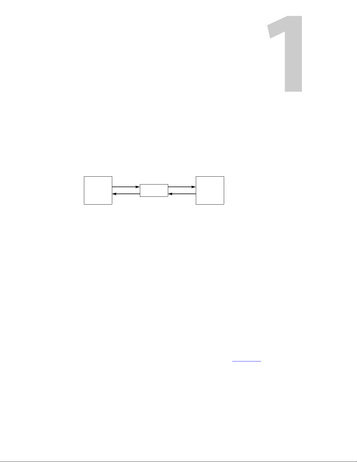
SMS7000 EC9535 Router
command
status
command
status
The EC9535 GSC Node Bus Converter is a communications protocol converter that allows
Miranda’s NV8288, NV8288-Plus and NV8500 family routers to communicate with an SMS7000
router control system.
A router must have (1) a GSC Node Bus connector and (2) a control card that follows the
SMS7000 protocol. The NV8288, NV8288-Plus and the NV8500 family routers do not have these
items.
The EC9535 has the GSC Node Bus connector and the control cards that follow the SMS7000
protocol. The SMS7000 connects to the EC9535, which in turn, connects to the router:
The EC9535 interprets commands from the SM7000, sending equivalent commands to the
router. It also interprets status mesages from the router, returning their equivalent to the
SMS7000.
Product Overview
The EC9535 GSC Node Bus Converter is used as an interface between a SMS7000 system
controller and a specific Grass Valley router. Unlike a router, the EC9535 does not actively
manage signals. Instead the EC9535 provides a GSC Node Bus to serial interface that enables a
SMS7000 system controller to communicate wit h Miranda routers that feature only serial
system controller connections. In addition, the EC9535 provides high reliability through redundant power supplies and redundant control cards, as well as deterministic communications
processing.
Mounting
The EC9535 GSC Node Bus Converter mounts in a rack with minimum dimensions of 2RU high
(3.47 inches, 88.1mm), and 16.0 inches (406 mm) deep. When placing the rack in your facility, be
sure to leave enough space for air flow through the front and rear of the EC9535 and within easy
access of an AC power source. For mounting instructions, see Rack Mount
Fuses
The EC9535 GSC Node Bus Converter has no user-serviceable fuses.
on page 10.
1
Page 10
Introduction
EC9535
GSC Node Bus Converter
Frame Front
Cooling
The EC9535 GSC Node Bus Converter has one fan providing forced air cooling. The fan is
accessed from the front of the frame. The fan draws cooling air from the front of the frame,
through the door, and exhausts it through a grill in the rear door. The EC9535 must have the
door correctly installed and closed for proper airflow through the chassis.
Power Supply
Power for the EC9535 is supplied through the Grass Valley PS0007 power supply module. The
PS0007 power supply module accepts a wide range of AC input voltages and produces +48 VDC
outputs. The power supply automatically senses the AC input voltage range (90–130 and 180–
250 VAC) and adjusts to maintain a relatively constant DC output; no voltage selection is
required.
Frame Front
If airflow is impeded, overheating may occur.
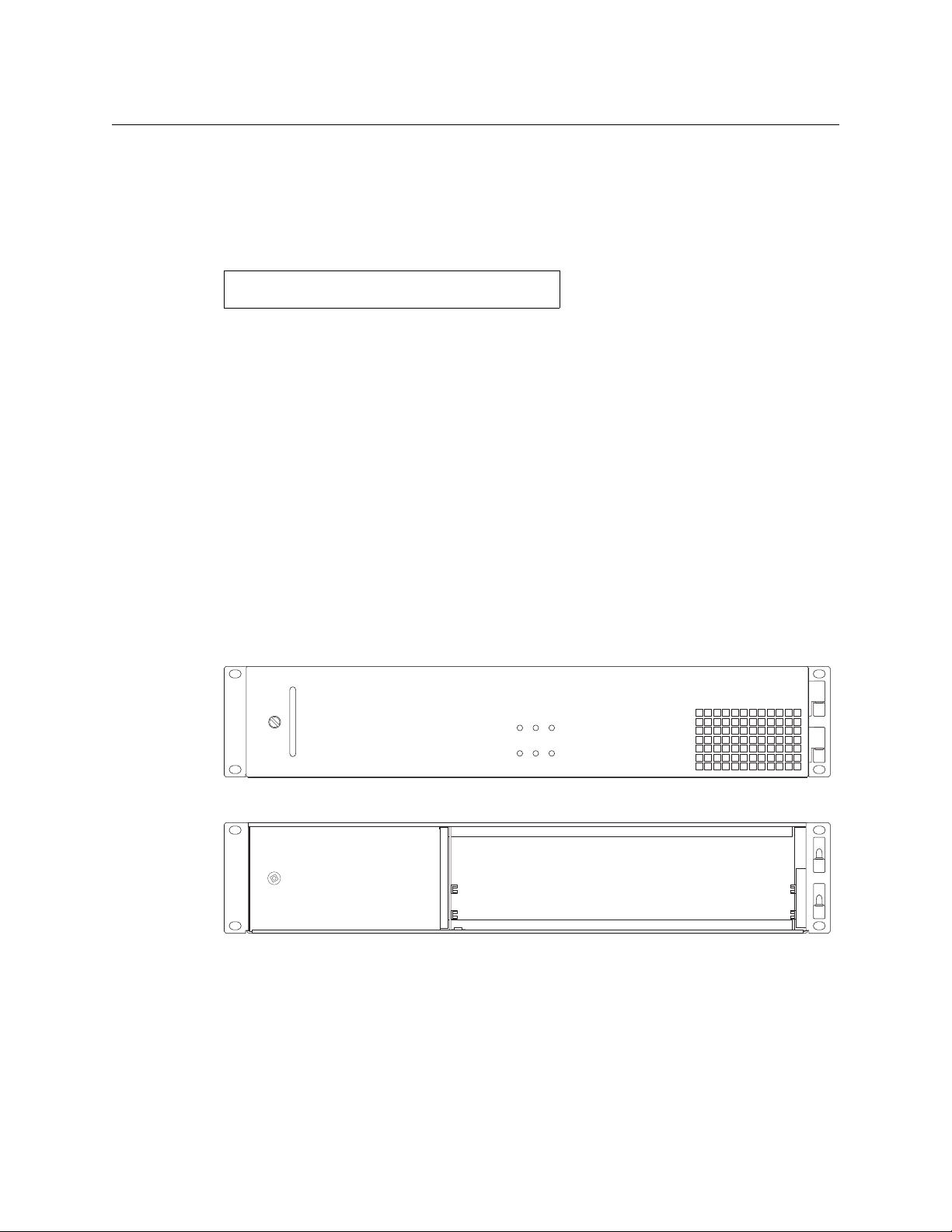
The front of the EC9535 GSC Node Bus Converter features a single door. When facing the front of
the frame the right-hand side features an open grill through which a fan draws cooling air. A
handle is provided on the left-hand side. The door is hinged on the right-hand side and swings
open from left to right. By opening the door, you can access the control cards.
Figure 1-1 shows the front of the EC9535 with the door closed. Figure 1-1 shows the EC9535
with the door removed. The card guides that house the control cards are visible.
Fig. 1-1: Front of EC9535 with Door Closed
Fig. 1-2: Front of EC9535 with Door Removed
2
Control Cards
The EC9535 has two control cards (EM0374), one primary and one secondary. The secondary
card is optional and used as a redundant, or stand-by, controller. Each control card is equipped
with a special mezzanine (SM0220) that facilitates communication between the control cards
and the SMS7000 system controller. Each card receives commands from a router control system,
Page 11
and in turn, sends commands to the connected router’s control cards. Only the active control
VIDEO
REF 2
VIDEO
REF 1
ALARMS
TIME
CODE
LOOP LOOP LOOP
SEC
CTRL
LOOP
THRU
10/100BT
10 B 2
PRI
CTRL
10 B 2
10/100BT
AES
REF 1
AES
REF 2
DIAG
DIAG
CTRL1 CTRL 2
CTRL1 CTRL 2
E146905
card sends commands. The active control card updates the stand-by control card.
Both the primary control card and the secondary control card receive commands from the
router control system, but only the active control card responds. Because both cards receive
router control system commands, if the active control card fails, the stand-by control card automatically takes over processing without interruption. In addition, the primary control card and
secondary control card communicate with each other. Should either control card fail, the newly
active control card communicates the failure to the router control system.
Four LEDs on the front of the control card indicate the card’s status: low battery (red), alarm
(red), active (amber), and operating normally (green). For more information, see Indicator LEDs
on page 21.
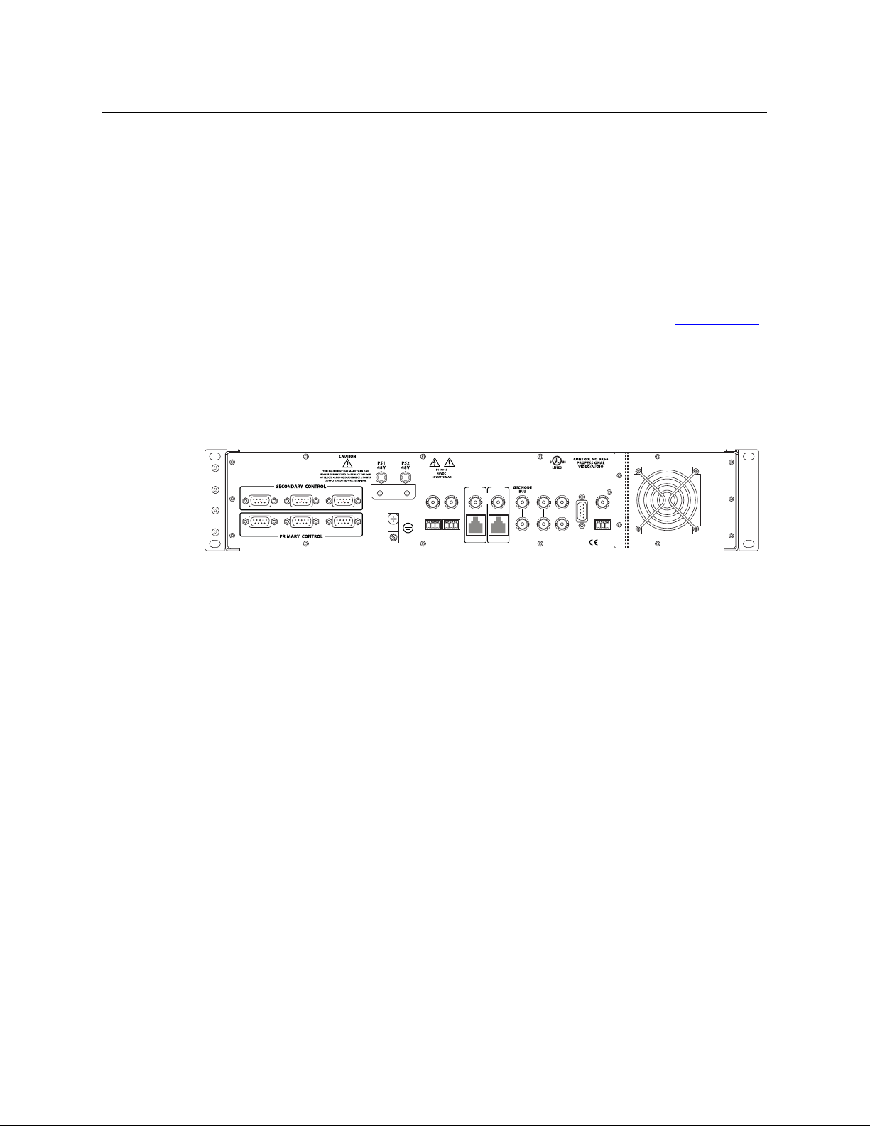
Rear Connections
The rear of the EC9535 frame features a back plate containing several connections for managing
system functions and two power connections:
EC9535
Reference Manual
Fig. 1-3: EC9535 (Rear View)
These connections enable you to connect to a system controller, reference signals, power
sources and system alarms. When facing the rear of the frame, the far right-hand side has a grill
behind which is located the fan for frame cooling. All system and power connections are located
to the left of the fan.
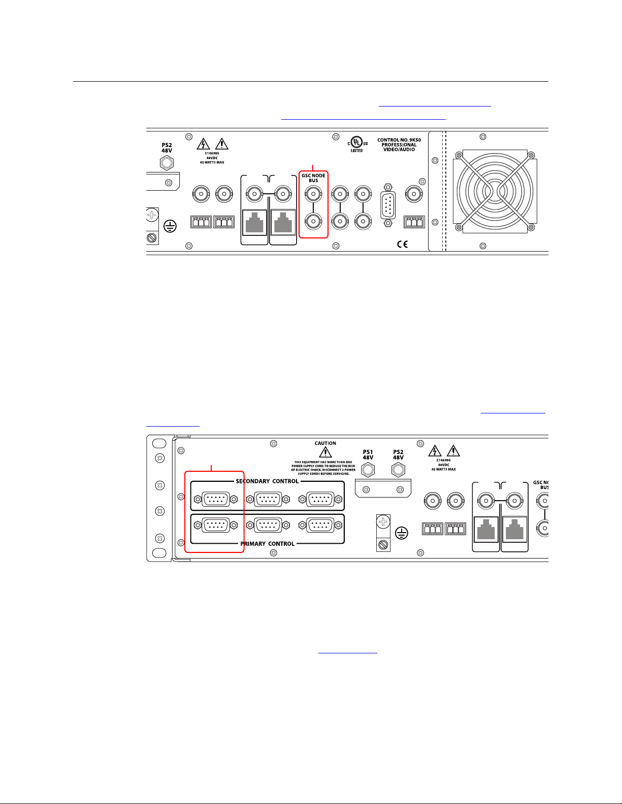
GSC Node Bus Control Connections
The EC9535 GSC Node Bus Converter has one port labeled ‘GSC NODE BUS’, as shown in
Figure 1-4. This connection is used to connect a SMS7000 system controller to the EC9535. In
turn, the EC9535 is connected to a NV8288, NV8288-Plus or NV8500 Family router. Through the
GSC Node Bus connection, the SMS7000 router control system sends commands to both the
EC9535’s primary and secondary control cards. In turn, the control cards forward the commands
3
Page 12
Introduction
VIDEO
REF 2
VIDEO
REF 1
ALARMS
TIME
CODE
LOOP LOOP LOO P
SEC
CTRL
LOOP
THRU
10/100 BT
10 B 2
PRI
CTRL
10 B 2
10/100 BT
AES
REF 1
AES
REF 2
DIAG
DIAG
E146905
GSC Node Bus
Connector
LOO
SEC
CTRL
LOOP
THRU
10/100 BT
10 B 2
PRI
CTRL
10 B 2
10/100 BT
AES
REF 1
AES
REF 2
DIAG
DIAG
CTRL 1 CTRL 2
CTRL 1 CTRL 2
Serial Connections
to Control System
Rear Connections
to the attached router through serial connections. (See Serial Control Connections on page 4.)
For installation instructions, see Making System Controller Connections
Fig. 1-4: GSC Node Bus Control Connection (Rear View)
on page 11.
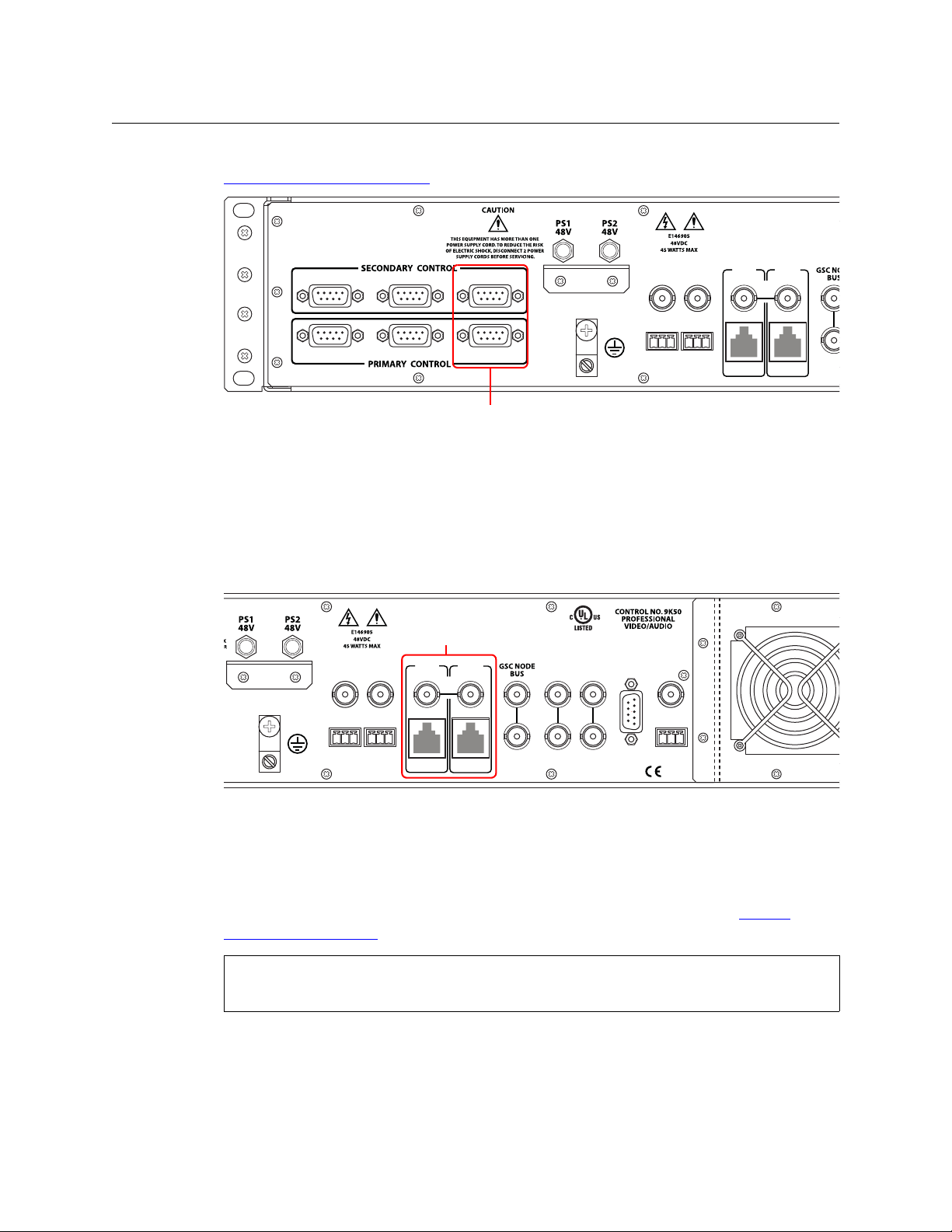
Serial Control Connections
Figure 1-5 shows the serial control connections to the router. The ports are divided into two sets,
one primary control and one secondary control. Primary control is the connection to a router’s
primary control card. Secondary control is the connection to a router’s secondary control card
(which is optional for redundancy). Each set is further divided into connections that correspond
to router control systems: ‘CTRL 1’ corresponds to the primary control system and ‘CTRL 2’ corresponds to an alternate control system. Only ‘CTRL 1’ is used. ‘CTRL 2’ is not used because there is
no alternate control system (i.e., backup system) for the SMS7000 system controller. However,
the connection is provided for future flexibility. For installation instructions, see Making Router
Connections on page 12.
4
Fig. 1-5: Serial Control Connections (Rear View)
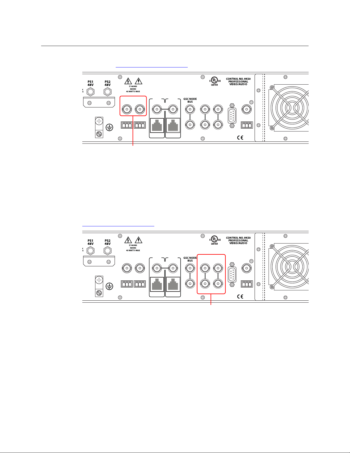
Diagnostic Connections
The diagnostic connections enable the EC9535 to communicate with the UniConfig application.
UniConfig runs on a PC separate from the EC9535 and is used to perform system setup tasks,
and configure and monitor EC9535. (See Configuration
User’s Guide.
Diagnostic connections connect the EC9535 to the computer (PC) running the UniConfig application. Two diagnostic connections are located on the rear of the EC9535, labeled ‘DIAG’. The
ports are divided into two sets: one primary and one secondary, as shown in Figure 1-6 on page
5. The primary control connects to EC9535’s primary control card. The secondary control
on page 19.) See also the UniConfig
Page 13
EC9535
LOO
SEC
CTRL
LOOP
THRU
10/100 BT
10 B 2
PRI
CTRL
10 B 2
10/100 BT
AES
REF 1
AES
REF 2
DIAG
DIAG
CTRL 1 CTRL 2
CTRL 1 CTRL 2
Diagnostic Connections
VIDEO
REF 2
VIDEO
REF 1
ALARMS
TIME
CODE
LOOP LOOP LOO P
SEC
CTRL
LOOP
THRU
10/100 BT
10 B 2
PRI
CTRL
10 B 2
10/100 BT
AES
REF 1
AES
REF 2
DIAG
DIAG
E146905
Ethernet
Connections
Reference Manual
connects to EC9535’s secondary (optional for redundancy) control card. For instructions, see
Making Diagnostic Connections
Fig. 1-6: Diagnostic Connections (Rear View)
on page 13.
Ethernet Connections
The EC9535 has two Ethernet ports, labeled ‘10/100BT’, as shown in Figure 1-7. These ports are
divided into two sets, one primary (‘PRI CTRL’) and one secondary (‘SEC CTRL’). These connections can be used to connect to a PC running UniConfig. However, in general these connections
are not used at this time and provided for future network use.
Fig. 1-7: Ethernet Control Connections (Rear View)
In order for EC9535 to communicate with UniConfig through an Ethernet connection, you must
configure an IP address for each of EC9535’s control cards. The IP address is set using UniConfig.
However, UniConfig runs on a PC and cannot communicate with EC9535 until an IP address has
been entered. Therefore, you must use a serial connection
— the ‘DIAG’ port(s) — to communi-
cate with the computer (PC) running UniConfig to define the IP address(es). See Making
Diagnostic Connections on page 13.
If using an Ethernet connection, 50ohm terminators must be installed on the ‘10 B 2’
connectors.
AES Reference Connections
The AES reference is used for clock generation, which provides a timing reference for AES
synchronous signals and for timing circuits on the EC9535 control card. This reference is not
5
Page 14
Introduction
VIDEO
REF 2
VIDEO
REF 1
ALARMS
TIME
CODE
LOOP LOOP LOO P
SEC
CTRL
LOOP
THRU
10/100 BT
10 B 2
PRI
CTRL
10 B 2
10/100 BT
AES
REF 1
AES
REF 2
DIAG
DIAG
E146905
AES Reference Connectors
VIDEO
REF 2
VIDEO
REF 1
ALARMS
TIME
CODE
LOOP LOOP LOO P
SEC
CTRL
LOOP
THRU
10/100 BT
10 B 2
PRI
CTRL
10 B 2
10/100 BT
AES
REF 1
AES
REF 2
DIAG
DIAG
E146905
Video Reference
Connectors
Rear Connections
currently used, but provided for future flexibility. For more information, contact Technical
Support. (See Grass Valley Technical Support
Fig. 1-8: Connections to AES References (Rear View)
on page 35.)
Video Reference
The EC9535 provides timing reference connections for video signals, labeled ‘VIDEO REF 1’ and
‘VIDEO REF 2’, as shown in Figure 1-9. Located on the rear of the frame, these connections
provide a reference input for determining the video frame switch point. The video reference
connections require a stable source of PAL, NTSC or Tri-level sync. This reference is not currently
used, but provided for future flexibility. For more information, contact Technical Support. (See
Grass Valley Technical Support
on page 35.)
Fig. 1-9: Connections to Video References (Rear View)
6
Page 15
EC9535
VIDEO
REF 2
VIDEO
REF 1
ALARMS
TIME
CODE
LOOP LOOP LOO P
SEC
CTRL
LOOP
THRU
10/100 BT
10 B 2
PRI
CTRL
10 B 2
10/100 BT
AES
REF 1
AES
REF 2
E146905
Time Code Connector
VIDEO
REF 2
VIDEO
REF 1
ALARMS
TIME
CODE
LOOP LOOP LOO P
SEC
CTRL
LOOP
THRU
10/100 BT
10 B 2
PRI
CTRL
10 B 2
10/100 BT
AES
REF 1
AES
REF 2
E146905
System Alarm Connector
Reference Manual
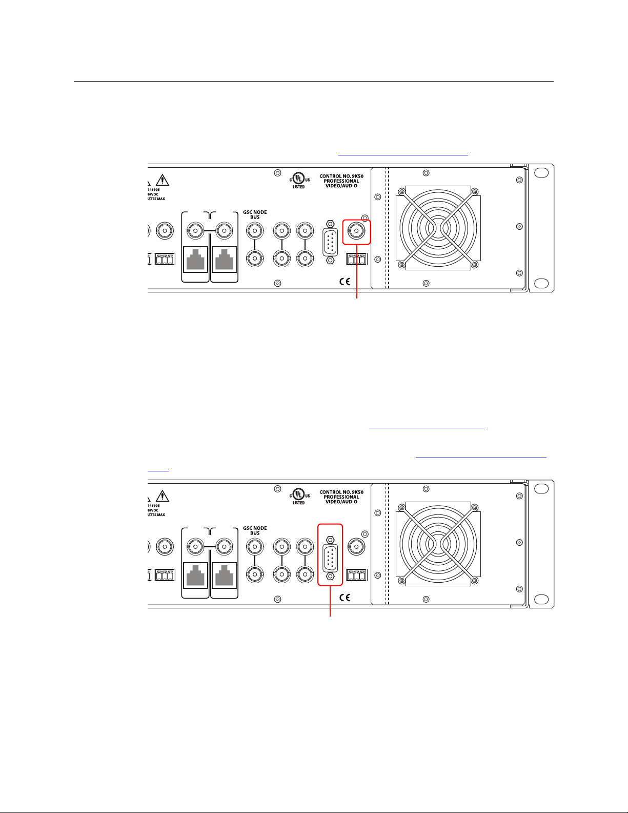
Time Code Reference Connection
There is a single Time Code reference connection labeled ‘TIME CODE’, as shown in Figure 1-10.
This reference is not currently used in the EC9535, but provided for future flexibility. For more
information, contact Technical Support. (See Grass Valley Technical Support
Fig. 1-10: Time Code Reference Connection (Rear View)
on page 35.)
System Alarm
The EC9535 has a system alarm that sends notification of a malfunction, such as when a fan or
power supply is not functioning properly. The alarm connection can be connected to external
equipment that display visual signals when an alarm is activated. Creation of an external alarm
indicator is outside the scope of this manual, however basic instructions on wiring the alarm
connection for external monitoring is provided. See Alarm Indicator Equipment
The alarm connection is labeled ‘ALARMS’ and is located on the rear of the EC9535, as shown in
Figure 1-11. For instructions on making alarm connections, see Making System Alarm Connec-
tions on page 15.
Fig. 1-11: System Alarm Connection (Rear View)
on page 15.
7
Page 16

Introduction
Rear Connections
8
Page 17

Installation
When setting up an EC9535 GSC Node Bus Converter for the first time, or reconfiguring an
existing configuration, there are certain steps that must be performed. It is recommended that
initial installation and later reconfiguration tasks be performed in a specific order to avoid
possible complications.
Perform installation and reconfiguration tasks in the following order. If you are reconfiguring,
only perform the step related to the configuration you are changing:
1 Mount the EC9535 in a rack. See Rack Mount
2 Make connections between the EC9535 and the SMS7000 system controller. See Making Sys-
tem Controller Connections on page 11.
3 Make connections between the EC9535 and the router. See Making Router Connections
page 12.
4 Make diagnostic connections. Diagnostic connections enable the router and UniConfig to
communicate. This is important when initially configuring the router and any time the router
is reconfigured. See Making Diagnostic Connections
5 Connect the alarm connection on the router to an external indicator. See Making System
Alarm Connections on page 15.
6 Connect power. See Connecting to Power
7 Install UniConfig. If reconfiguring, UniConfig does not need to be reinstalled. See the Uni-
Config User’s Guide.
on page 10.
on
on page 13.
on page 16.
Package Contents
When your EC9535 products from Grass Valley arrive, immediately inspect the shipping
container for any obvious damage. If the container is damaged, unpack and inspect the
contents. If the contents are damaged, notify the carrier immediately.
When unpacking the shipping container, look for the packing slip and compare it against the
contents to verify that everything ordered was received. If anything is missing (or if equipment is
damaged unrelated to shipping), please contact Miranda. For contact information, see Grass
Valley Technical Support on page 35.
The package does not contain a mounting rack, network cables, mounting screws, or grounding
wire.
9
Page 18

Installation
Preparing for Installation
Preparing for Installation
You will need the following items before getting started:
Rack Mount
The EC9535 is designed to mount in a 19″ (482.6 mm) EIA rack.
How to Rack Mount the EC9535
A PC running Windows
required for system configuration.
PC hardware requirements:
CD drive.
EIA-232 serial COM port (DE9) capable of operating at 38.4kbps.
10BaseT or 10/100BaseT (preferred) Ethernet port.
Ethernet cables (category 5) with RJ-45 connectors. (optional)
EIA-232 serial cable with DE9 connectors, wired straight-through, male to female.
75
Ω BNC connector and coaxial cable.
Frame rack suitable for mounting EC9535.
1 Determine the placement of the EC9535 and the rack in the facility. When placing the frame
and rack, be sure to locate the rack near an accessible AC source power outlet. The AC source
is used to power the frame.
2 Lift the frame into position and attach it to the front of the rack with the appropriate screws.
Be sure to place screws in all frame mounting screw holes.
3 If open, close the front door. This ensures proper airflow for frame cooling.
®
2000 or higher, or Windows XP Professional.® This PC is
Installing Control Cards
The EC9535 comes with two control cards (EM0374) already installed. Each control card has a
mezzanine (SM0220) designed to communicate with the SMS7000 control system. The
following are instructions for installing control cards, should the need arise.
Cards are inserted by sliding them into card guides through the front of the frame.
10
Page 19

EC9535
Control Card Guides
VIDEO
REF 2
VIDEO
REF 1
ALARMS
TIME
CODE
LOOP LOOP LOO P
SEC
CTRL
LOOP
THRU
10/100 BT
10 B 2
PRI
CTRL
10 B 2
10/100 BT
AES
REF 1
AES
REF 2
DIAG
DIAG
E146905
GSC Node Bus
Connector
Reference Manual
How to install control cards
Do not drop, roughly handle, or stack circuit boards. If you cannot easily insert or remove a
board, stop and contact Grass Valley Technical Support.
1 Open the door at the front of the frame. The door is hinged on the right-hand side and
swings from left to right. Use the handle on the left-hand side to gently pull the door open.
2 There are two control card guides, as shown in Figure 2-1. Insert each control card horizon-
tally into each set of guides. The cards should slide in easily; do not force them.
Fig. 2-1: Front of EC9535 with Door Removed
3 For each card, press the lever(s) inward, making sure each card is fully seated in its slot.
4 Close the frame door. The door must be closed for the router cooling system to work prop-
erly.
Making System Controller Connections
In order for a SMS7000 system controller and a NV8288, NV8288-Plus or NV8500 Family router to
communicate, the system controller must be connected to an EC9535. The SMS7000 system
controller is connected using the ‘GSC NODE BUS’ connection located on the rear of the EC9535
frame. The connection uses a 75
How to Make SMS7000 System Controller Connections
1 Locate the GSC Node Bus connections on the rear of the router, as shown in Figure 2-2. Sys-
tem controller connections are labeled ‘GSC NODE BUS’.
Ω BNC connector and coaxial cable.
Fig. 2-2: GSC Node Bus Control Connection (Rear View)
2 Connect to the ‘GSC NODE BUS’ connection using a 75 Ω BNC connector and coaxial cable.
11
Page 20

Installation
SEC
CTRL
LOOP
THRU
10/100 BT
10 B 2
PRI
CTRL
10 B 2
10/100 BT
AES
REF 1
AES
REF 2
DIAG
DIAG
CTRL 1 CTRL 2
CTRL 1 CTRL 2
Serial Connections to
Control System
P1
P2 P4
P3
Making Router Connections
3 Connect the other end of the cable to the SMS7000 system controller. For detailed instruc-
tions, refer to the SMS7000 documentation.
4 On the unused GSC Node Bus connection, terminate the loop-through by installing a 75
BNC terminator.
Making Router Connections
In order for a NV8288, NV8288-Plus or NV8500 Family router to communicate with a SMS7000
system controller, the router must be connected to an EC9535. The router is connected using
the serial control system connections, located on the rear of the EC9535, and a cable provided
by Miranda (WC0152). The proprietary cable is 20 feet (6.096 meters) long with two DE9 (a.k.a.
DB9) connectors on each end for a total of four DE9 connectors.
The serial control ports are divided into two sets that enable the primary control card or the
secondary control card in the EC9535 frame to communicate with the corresponding control
card in the router frame.
How to Make Router Control Connections
1 Locate the serial control connections on the rear of the router, as shown in Figure 2-3. Serial
control connections are labeled ‘PRIMARY CONTROL’ for the primary control card and ‘SECONDARY CONTROL’ for the secondary control card.
Ω
Fig. 2-3: Serial Control Connections (Rear View)
2 Locate the cable WC0152 provided with the EC9535. The cable has four DE9 connectors as
shown:
Fig. 2-4: WC152 Cable for connecting to router
12
Page 21

3 Facing the rear of the EC9535 frame, make connections as follows:
• Connect the DE9 connector labeled ‘P1’ to the ‘CTRL 1’ connection in the ‘PRIMARY CON-
TROL’ section.
• Connect the DE9 connector labeled ‘P2’ to the ‘CTRL 1’ connection in the ‘SECONDARY
CONTROL’ section.
4 Facing the rear of the router, locate the router control serial connections:
• On the NV8288 and NV8288-Plus, the section is labeled ‘PRI CTRL’ and ‘SEC CTRL’
• On the NV8500 Family routers (NV8144, NV8280 or NV8576) the section is labeled ‘PRI’
and ‘SEC’.
5 Make connections as follows:
• Connect the DE9 connector labeled ‘P3’ to the ‘CTRL 1’ connection in the ‘PRI CTRL’ or
‘PRI’ section, depending on the router.
• Connect the DE9 connector labeled ‘P4’ to the ‘CTRL 1’ connection in the ‘SEC CTRL’ or
‘SEC’ section, depending on the router.
Making Diagnostic Connections
EC9535
Reference Manual
The diagnostic connections enable the EC9535 to communicate with the UniConfig application.
UniConfig is installed on a unit, separate from the router (e.g., PC), and is used to perform system
setup tasks, and configure and monitor the EC9535. For information about using UniConfig, see
the UniConfig User’s Guide.
There are two sets of diagnostic connections: one set is located on the front of the control cards
and one set is located on the rear of the EC9535, labeled ‘DIAG’. Which is used is entirely up to
you and your facility needs. Usually the control card connection is used when the diagnostic
connection to UniConfig is temporary. The diagnostic connections on the rear of the EC9535
frame are most often used to make a permanent connection to UniConfig. For a detailed
description of the serial connections, see Diagnostic Connections
on page 4.
Control Card Diagnostic Connections
A temporary diagnostic connection can be created using the DE9 port located on the front of
the primary control card. The baud rate for this port is locked to 9600.
How to Make Control Card Diagnostic Connections
1 Facing the front of the EC9535, open the door and locate the primary control card slot. The
primary control card is located on top (above) and the secondary control card is located
below. (See Figure 2-1 on page 11.)
2 On the front of the control card is a single serial port. Connect to the serial port using a DE9
connector and a serial cable.
The following lists the DE9 pin connectors for RS-232:
PC End (DCE) Pin Router End (DTE)
DCD 1 Ground
RXD 2 TXD
13
Page 22

Installation
SEC
CTRL
LOOP
THRU
10/100 BT
10 B 2
PRI
CTRL
10 B 2
10/100 BT
AES
REF 1
AES
REF 2
DIAG
DIAG
CTRL 1 CTRL 2
CTRL 1 CTRL 2
Diagnostic Connections
Making Diagnostic Connections
PC End (DCE) Pin Router End (DTE)
TXD 3 RXD
DTR 4 DSR
Signal Ground 5 Signal Ground
DSR 6 DTR
RTS 7 CTS
CTS 8 RTS
Ground 9 Ground
3 Connect the other end of the cable to the PC running the UniConfig application using a DE9
connector.
4 When done configuring, remove the temporary connection.
Frame Diagnostic Connections
There are two diagnostic ports located on the rear of the EC9535, labeled ‘DIAG’. The diagnostic
ports are fixed at 38400 baud, RS-232. For more information, see the UniConfig User’s Guide.
14
How to Make Frame Diagnostic Connections
1 Locate the diagnostic connections on the rear of the EC9535, as shown in Figure 2-5. The
diagnostic connections are labeled ‘DIAG’.
Fig. 2-5: Diagnostic Connections (Rear View)
2 Connect to the ‘DIAG’ connection in the ‘PRI’ section using a DE9 connector and a serial
cable. The ports are set for RS-232:
The following lists the DE9 pin connectors for RS-232:
PC End (DCE) Pin Router End (DTE)
DCD 1 Ground
RXD 2 TXD
TXD 3 RXD
DTR 4 DSR
Signal Ground 5 Signal Ground
Page 23

PC End (DCE) Pin Router End (DTE)
VIDEO
REF 2
VIDEO
REF 1
ALARMS
TIME
CODE
LOOP LOOP LOO P
SEC
CTRL
LOOP
THRU
10/100 BT
10 B 2
PRI
CTRL
10 B 2
10/100 BT
AES
REF 1
AES
REF 2
E146905
System Alarm Connector
DSR 6 DTR
RTS 7 CTS
CTS 8 RTS
Ground 9 Ground
3 Connect the other end of the cable to the PC running the UniConfig application.
4 If a secondary (optional for redundancy) control card is installed, connect to the ‘DIAG’ con-
nection in the ‘SEC’ section using a DE9 connector and a serial cable as described in step 2
and step 3.
Making System Alarm Connections
The EC9535 provides a system alarm that notifies you of a malfunction, such as when a fan or
power supply is not functioning properly. And alarm can be connected to an external alarm
indicator that displays visual cues when the alarm is activated. Grass Valley does not provide
external indicator equipment, but does provide instructions on wiring the alarm connections.
See Alarm Indicator Equipment
on page 15.
EC9535
Reference Manual
How to Make Alarm Connections
1 On the rear of the router, locate the ‘ALARMS’ connector:
Fig. 2-6: System Alarm Connection (Rear View)
2 Connect to the ‘ALARMS’ connection using a DE9 connector and cable.
3 Connect the other end of the cable to an external alarm indicator. See “
Alarm Indicator
Equipment” on this page for information on wiring the DE9 connector.
Alarm Indicator Equipment
An external alarm indicator can be created to display visual cues when a failure has occurred on
the EC9535 frame. LEDs can be wired to specific pins on a DE9 connector such that each LED
indicates what specific router module has failed.
The ‘ALARM’ connection on the rear of the EC9535 uses a DE9 connector. An “alarm” or ON
condition occurs when the connection between an alarm pin and Alarm_COM (common)
15
Page 24

Installation
Typical Circuit 1
Customer-supplied relay
contacts NC, (but open during
alarm condition)
External Power,
30VDC max, 150 mA max
Normally ON, the LEDs turn off to indicate failure
1
COM
Normally OFF, the LEDs turn on to indicate failure
30VDC max, 150 mA max
External Power
1
12345
6789
1
2
3
4
5
Alarm COM
Alarm 1
Alarm 2
Alarm 3
Alarm 4
8
7
8
9
Alarm 5
Alarm 6
Alarm 7
Alarm COM
Typical Circuit 2
COM
Connecting to Power
opens. The alarm turns OFF when the connection between Alarm_COM and the alarm pin closes
again.
To create an indicator box, connect to the ‘ALARM’ connection using a DE9 female connector,
wiring as shown in Figure 2-7. Each pin monitors a specific function and activates a specific
alarm.
Connecting to Power
Fig. 2-7: Alarm Connections and On/Off Switches
The following lists each DE9 pin and the associated alarm. The pin number listed corresponds to
the pin numbers in Figure 2-7 on page 16:
PIN Signal Description Possible Conditions Causing the Alarm
1, 9 Alarm_COM Common Common connection for all alarm pins.
2 Alarm_1 Major Alarm Indicates missing reference inputs, or missing power sup-
plies.
3 Alarm_2 Minor Alarm Alarm_3, or Alarm_4, or Alarm_5, or Alarm_6
4 Alarm_3 Power Supply Missing power supply module.
5 Alarm_4 Video Ref Missing Video Ref 1 or Video Ref 2.
6 Alarm_5 AES Ref Not used in EC9535.
7Alarm_6Fans or Tempera-
ture
8 Alarm_7 Control Module
Health
The EC9535 uses a proprietary power supply (PS0007) to connect to an AC power source (90–
230 VAC, 50–60 Hz).
Indicates a fan failure or module over temperature.
Any control module not “healthy.”
16
Page 25

EC9535
VIDEO
REF 2
VIDEO
REF 1
ALARMS
LOOP LOOP LOO P
SEC
CTRL
LOOP
THRU
10/100 BT
10 B 2
PRI
CTRL
10 B 2
10/100 BT
AES
REF 1
AES
REF 2
DIAG
DIAG
CTRL 1 CTRL 2
CTRL 1 CTRL 2
E146905
Power Connections
Ground Lug
Reference Manual
How to Connect to Power
1 Locate the power connections on the rear of the EC9535. The connections are labeled ‘PS1
48V’ and ‘PS2 48V, as shown in Figure 2-8.
Fig. 2-8: Power Connections and Ground Lug (Rear View)
2 Connect one cable (PS0007) to ‘PS1’. Figure 2-9 is an example of the PS0007 DC power cord.
Fig. 2-9: PS0007 DC Power Cord
3 Connect the other end of the cable to a source of AC power.
To protect against accidentally disconnecting the cable from the power source, loop a
cable tie or similar restraint around the cable and through the retention plate.
4 Repeat step 2 and step 3 for the ‘PS2 48V’ connection.
5 Connect the EC9535’s ground lug to earth ground using a copper wire from 14 to 6 AWG.
The ground lug is located in the lower right corner of the frame, as shown in Figure 2-8 on
page 17.
17
Page 26

Installation
Connecting to Power
18
Page 27

Configuration
Before being placed into service, the EC9535 must be configured for your particular router
control system and settings. Configuration is managed through UniConfig, which resides on a
PC and is separate from the router. For information on using UniConfig, see the UniConfig User’s
Guide. For instructions on configuring EC9535, see the section “Configuring EC9535” within the
UniConfig User’s Guide.
When configuring the EC9535, the EC9535’s ‘CTRL 1’ serial port must be set to the same baud
rate as the controlled router’s ‘CTRL 1’ serial port rate. (See Serial Control Connections
page 4.) By default, the NV8288, NV8288-Plus and NV8500 Family routers have the ‘CTRL 1’ ports
set to 38,400 baud. However, the number of destinations that can be switched per frame in a
system using a SMS7000 system controller, an EC9535, and a NV8288, NV8288-Plus or NV8500
Family router is determined by the EC9535 and the router serial port baud rates. Because higher
rates may be used, you may want to set the serial ports at the highest available rate (115,200
baud) unless doing so results in communication errors. For information on setting the serial port
baud rates for routers, see the “Setting Up Communication” section within the UniConfig User’s
Guide.
on
19
Page 28

Configuration
20
Page 29

The EC9535 does not require any periodic electrical or physical maintenance. However, it is
recommended that the system’s indicator LEDs be checked on a regular basis to ensure that the
system is operating properly. (See Indicator LEDs
make sure cooling air flow to the power supply fans is unobstructed.
Only qualified service personnel should perform procedures in this section. There are no userserviceable fuses.
Indicator LEDs
Indicator LEDs indicate whether DC power is present and if a card is operating normally. LEDs
are visible when the router front door is closed.
LEDs are listed in the order they appear on the card, from right to left. The meanings of the LED
indicators are as follows:
LED Indicator Function
Red (low battery) Normally OFF. If lit, indicates that the battery needs replacing. See Battery Replace-
Red (alarm) Normally OFF. If lit, indicates a problem or fault. Check the external reference sig-
Yellow (active card) Normally ON. Indicates the card is the active control card. On the standby control
Green (health,
power)
Maintenance
on page 21.) It is also a good idea to regularly
ment on page 21.
nals. If that does not resolve the problem, refer to the system status window in UniConfig for additional information. If you cannot resolve the problem, call Grass
Valley Technical Support. For contact information, see Grass Valley Technical Sup-
port on page 35.
card, this LED should be OFF.
Normally ON. Indicates the card has power and is operating normally.
Battery Replacement
If the red Low Battery LED indicator on the control card is lit, the battery located on the front
edge of the card needs replacing. Grasp the exposed edge of the battery with your fingers and
pull it towards you to remove it.
Do not use a metallic tool to remove the battery.
Call
Grass Valley for replacement battery information. For contact information, see Grass Valley
Technical Support on page 35.
21
Page 30

Maintenance
Air Flow
When you insert the new battery, be careful to observe the correct polarity.
To prevent explosion of the battery and possible equipment damage or harm to
personnel, be sure the battery is oriented with the correct polarity. Polarity
markings are visible on the card’s battery housing.
Air Flow
A fan in the EC9535 frame draws cooling air from the front of the frame, through the door, and
exhausts heated air through the rear. The EC9535 must have the door correctly installed and
closed for proper airflow through the chassis. For maximum air flow, regularly inspect the fan. If
the fan becomes dusty, gently vacuum the fan and grills.
If airflow is impeded overheating may occur.
Obtaining Service
For service advice, warranty exchange, warranty repair, or out-of-warranty repair:
• Call Grass Valley Technical Support. (See Grass Valley Technical Support on page 35.) Our Ser-
vice Personnel will help you resolve any service issues.
• If you need an exchange or repair, Grass Valley will assign you a Return Material Authorization
(RMA) number. Do not return equipment without first receiving an RMA number.
Valley uses the RMA to track receipt of the equipment and to record repair or replacement
information.
• For out-of-warranty equipment, the Grass Valley Technical Support Engineer estimates the
cost of repair when you call and requests a purchase order payable to
• If repair or exchange is required, package the assembly in an antistatic bag and place it in a
shipping box with plenty of padding to prevent damage.
• Address the package using the Shipping Address listed in the front of this manual under
Grass Valley Technical Support on page 35, and ship the equipment to Grass Valley at your com-
pany’s expense.
• When repair or replacement of in-warranty equipment is complete, Grass Valley return ships
the items at our expense. For out-of-warranty equipment Grass Valley charges a shipping
and handling fee. The standard shipping method is second day.
• For out-of-warranty service, Grass Valley will send your company an invoice following the
repair or replacement.
Grass
Grass Valley.
22
Page 31

Technical Details
This section provides technical specifications for the of routers and the EC9535.
Power Specifications
Type Parameters
AC input 90–130/180–250VAC, 50/60Hz, auto-ranging
AC fuses No user serviceable fuses
AC connectors 2, PS0007
AC power usage 40 Watts, maximum
Mechanical Specifications
Type Parameter
Dimensions 2RU (3.47 inches, 88.1 mm) high
19.0 inches (483mm) wide
16.0 inches (406mm) deep
Weight 22 lbs, 9.97 kilograms
Mounting EIA 310-C, 19.0 inches (483 mm)
Grounding terminal Copper, accepts 14-6 AWG
Modules and slots 2 Control cards (1 primary, 1 optional secondary)
Diagnostic Type Serial port
Standard SMPTE 207M, EIA-422/EIA-232, configurable
Connector 2, DE9
Serial control Type Serial port (2 per control card)
Standard SMPTE 207M, EIA-422
Connector 4, DE9
Ethernet Type 10/100baseT
Standard IEEE 802.3
Protocol NVISION Ethernet protocol
Connector 2, RJ-45
GSC node bus Type Serial
Standard Proprietary
Connector 2, BNC, loop-thru, non-terminating pair
Impedance 75 Ω
23
Page 32

Technical Details
Environmental Specifications
Type Parameter
Operating temperature 0 to 40° Centigrade
Relative humidity 0 to 90%, non-condensing
Audio Specifications
Type Parameter
Audio Reference Input Type Serial digital audio
Standard AES3id
Sample Rate 48kHz
Connector 2, BNC (redundant)
Impedance 75 Ω
Input Level 0.5V pp to 2.0 Vpp
Video Specifications
Type Parameter
Video Reference Input Type Analog video reference
Standard PAL, NTSC or tri-level sync
Connector Loop-through, BNC
Impedance 75 Ω or Hi-Z (>20,000 Ω), not selectable
Input Level 0.5V pp to 2.0 Vpp
Input Return Loss >30 dB to 5 MHz
Time Code Specifications
Type Parameter
Time Code Reference Input Type 1 BNC
Standard SMPTE 12M
Connector BNC terminating
Data Rates 1/30th to 80 times normal
Impedance 75 Ω
24
Page 33

Part Numbers
This appendix provides a list of parts provided by Grass Valley for the EC9535.
Part Number Description
PS0007 AC to 48V DC Power supply
EM0374 Control card
SM0220 Mezzanine on control card for SMS7000 system controllers
WC0152 Proprietary router control system cable with 4 DE9 connectors.
FR0061 EC9535 frame
25
Page 34

Part Numbers
26
Page 35

Glossary
Active Cards See Modules.
AES Audio Engineering Society, Inc., New York, www.aes.org.
AES/EBU (Audio Engineering Society/European Broadcasting Union) a professional serial interface for
transferring digital audio from CD and DVD players to amplifiers and TVs. AES/EBU is typically
used to transmit PCM and Dolby Digital 5.1, but is not tied to any sampling rate or audio standard.
AES3, AES3id The AES routers support AES3id and provide 75Ω BNC connectors. AES3id is specified for 75Ω
coaxial cable up to 1000 meters. (AES3 uses 110Ω shielded twisted pair (STP) cable with XLR
connectors up to a distance of 100 meters.)
Analog Audio A signal where the instantaneous voltage is proportional to the diaphragm velocity at the
microphone.
Async AES,
Sync AES
AVC “Analog Video Conversion.” NVISION uses this abbreviation to describe a simple conversion tech-
Baud Rate Refers to the symbols per second or pulses per second. It is the unit of symbol rate, also known
DC Direct Current
dBu Unit of audio level where 0dBu is 0.775
DB25 A DB25 connector is the common 25-pin subminiature D connector. Most modern PCs use a
DE9 Sometimes mistakenly referred to as a DE9 connector, a DE9 connector is the common 9-pin
Device As the term is used in a NV9000 system, a device is a grouping of input and output ports that
EIA Electronic Industries Alliance. The EIA (until 1997 Electronic Industries Association) is a trade
The term “Async AES” refers to an asynchronous AES-compliant audio signal, whereas “Sync AES”
refers to a synchronous AES signal with a data rate of 48kbps. A system where various signals are
unlocked (not synchronized). Switching between signals leads to unpredictable results.
nique used to create an SD digital output signal from a composite analog video input, or to
describe the means by which SD signal is coded into an analog composite video output signal.
Path delay and subcarrier phase may not be precisely maintained in an AVC conversion path
within an NV5128 frame. AVC coding provides a cost-effective method to provide feeds to picture
monitors without requiring an external conversion device. AVC modules are not a substitute for
professional-grade format converters.”
as baud rate or modulation rate; the number of distinct symbol changes (signaling events) made
to the transmission medium per second in a digitally modulated signal or a line code.
Vrms.
female DB25 connector for the printer parallel port connector.
subminiature D connector. The serial port of modern PCs employ a male DE9 connector.
define a logical entity. (The logical entity does not have to be a real entity.) For example, a system
might have 3 levels: video, AES, and time code. A hypothetical device in this system is Camera 1,
which consists of video on input port 1 of the video router, AES on input port 5 of the AES router,
and time code on input port 8 of the time code router. (The EC9535 does presently include timecode routers.).
organization for electronics manufacturers in the United States. EIA is accredited by the American
27
Page 36

Glossary
National Standards Institute (ANSI) to help develop standards on electronic components,
consumer electronics, electronic information, telecommunications, and Internet security.
ESD Electrostatic discharge
HD HD and HD-SDI are equivalent in Grass Valley terminology. An HD signal is a high definition, serial
digital interface video format that conforms to the SMPTE 292M standard.
I/O Inputs and outputs are the physical connections (e.g., BNCs) on the back of the routing switcher.
The term “input port” is used interchangeably with “input” and the term “output port” is used
interchangeably with “output.”
Matrix 1. The rack-mounted EC9535 chassis or frame which contains the subassemblies (modules, back-
planes, power supplies, etc.) which comprise the EC9535.
2. An X-Y array of crosspoint switches, a crosspoint matrix.
Module 1. In the EC9535, modules are electronic assemblies that plug into the matrix. Modules include
but are not limited to input, output and controller printed circuit boards also called active cards.
2. Any removable subassembly may be referred to as a module. Router backplanes may occasionally be referred to as modules.
Operator The term operator usually refers to users other than the system administrator. An operator is
responsible for making most of the routes.
Physical Level In a GSC Node Bus Converter system, a physical level is the same thing as a router. The idea is that
multiple routers provide different “levels” on which to switch the signals of devices. Any particular device might send or receive HD, SD, AES, time-code, or machine-code signals. A GSC Node
Bus Converter switches one type, or level, of a device’s signal set.
Physically
Contiguous
Port A port is the physical connection on a router. In a configuration application system, a port can
Reference
Signal
RAM Random Access Memory
RJ45, RJ-45 Registered Jack, type 45 as defined in the United States Code of Federal Regulations. A common
RS-422 Sometimes referred to as RS-422 or TIA/RS-422-B and other similar variations. A bidirectional
RU Rack Units. A standard measure or size for frames (1.75 inches).
SD SD and SDI are equivalent terms in NVISION documents. An SD signal is a standard definition,
Source/Destination
Matrix modules are said to be in physically contiguous slots in a EC9535 frame when both the
inputs and outputs associated with those slots are in numerical sequence. For example, input
slots 5 and 6 are physically contiguous because inputs 1-16 and 17-32 are in numerical sequence.
In the same way, output slots 4 and 16 are contiguous because outputs 49-64 (slot 4) and 65-80
(slot 16) are in numerical sequence.
only be an input port or an output port.
A timing signal used to synchronize events such as the switching of video signals during a
specific portion of the vertical interval. Reference signals are externally applied. In their absence,
internally generated signals are used to sustain operation.
8-pin modular plug and/or jack used in the telecommunications and broadcast industry to transport Ethernet or machine control signals.
communications standard. The use of this term implies that NVISION intends to refer to the latest
standard in effect at the time the product was developed.
serial digital interface video format that conforms to the SMPTE 259M standard.
The term “source device” is used interchangeably with “source” and the term “destination device”
is used interchangeably with “destination.” A source is a device that is connected to one or more
28
Page 37

EC9535
Reference Manual
input ports. A destination is a device that is connected to one or more output ports. An example
of such a device would be a monitor.
A device can be both a source and destination. An example of such a device is a VTR.
SWB (Super Wide Band). A term originated by Grass Valley that refers to the ability of a router to pass
a wide range of digital bit rates and formats. Grass Valley’s SWB supports data rates from about
15
Mb/s to 1.5 GB/s.
Input signals must be nominally 800mV p-p and bi-level or tri-level in nature. The EC9535 video
routers bypasses re-clocking for non-video rates. Rates that are re-clocked include common SD
Sync AES,
Async AES
System
administrator
data rates of 143 and 270
nally 1.485
Gb/s. SWB accepts SD at 177 Mb/s, but does not reclock it.
The term “Async AES” refers to an asynchronous AES-compliant audio signal, whereas “Sync AES”
refers to a synchronous AES signal with a data rate of 48
The system administrator is the person responsible for installing, configuring, and maintaining a
router control system.
Mb/s (SMPTE 259M-A and -C, but not B or D) and HD data rates at nomi-
kb/s.
Time Code A linear time code signal complying with SMPTE 12M or the corresponding EBU standard.
UniConfig A Windows-based application (Universal Configuration) used to configure NVISION products
using a serial or Ethernet connection. UniConfig uses an easy-to-learn GUI (Graphical User Interface) to simplify the configuration process.
29
Page 38

Glossary
30
Page 39

Index
A
AC power . . . . . . . . . . . . . . . . . . . . . . . . . . . . . . . . . . . . . . . . .2, 16
Active cards, defined . . . . . . . . . . . . . . . . . . . . . . . . . . . . . . . . . 27
AES Reference connection . . . . . . . . . . . . . . . . . . . . . . . . . . . . 5
AES, defined . . . . . . . . . . . . . . . . . . . . . . . . . . . . . . . . . . . . . . . . . 27
AES/EBU, defined . . . . . . . . . . . . . . . . . . . . . . . . . . . . . . . . . . . . 27
AES3, defined . . . . . . . . . . . . . . . . . . . . . . . . . . . . . . . . . . . . . . . 27
AES3id . . . . . . . . . . . . . . . . . . . . . . . . . . . . . . . . . . . . . . . . . . . . . . 27
Africa, contact . . . . . . . . . . . . . . . . . . . . . . . . . . . . . . . . . . . . . . . 35
Agreement, license . . . . . . . . . . . . . . . . . . . . . . . . . . . . . . . . . . . iii
Air flow . . . . . . . . . . . . . . . . . . . . . . . . . . . . . . . . . . . . . . . . . . . . 2, 22
Alarm connection, diagram . . . . . . . . . . . . . . . . . . . . . . . . . . 16
Alarm connections . . . . . . . . . . . . . . . . . . . . . . . . . . . . . . . . . . . 15
Americas, contact . . . . . . . . . . . . . . . . . . . . . . . . . . . . . . . . . . . . 35
Analog audio, defined . . . . . . . . . . . . . . . . . . . . . . . . . . . . . . . 27
Asia, contact . . . . . . . . . . . . . . . . . . . . . . . . . . . . . . . . . . . . . . . . . 35
Asynchronous AES3, defined . . . . . . . . . . . . . . . . . . . . . . . . . 27
Audio Engineering Society . . . . . . . . . . . . . . . . . . . . . . . . . . . 27
AVC, defined . . . . . . . . . . . . . . . . . . . . . . . . . . . . . . . . . . . . . . . . 27
B
Battery replacement . . . . . . . . . . . . . . . . . . . . . . . . . . . . . . . . . 21
Baud rate, defined . . . . . . . . . . . . . . . . . . . . . . . . . . . . . . . . . . . 27
BNC connectors . . . . . . . . . . . . . . . . . . . . . . . . . . . . . . . . . . . . . 27
Connectors
AES reference . . . . . . . . . . . . . . . . . . . . . . . . . . . . . . . . . . . . .5
BNC . . . . . . . . . . . . . . . . . . . . . . . . . . . . . . . . . . . . . . . . . . . . .27
DB25 . . . . . . . . . . . . . . . . . . . . . . . . . . . . . . . . . . . . . . . . . . . .27
DE9 . . . . . . . . . . . . . . . . . . . . . . . . . . . . . . . . . . . . . . . . . . . . . .27
Diagnostic . . . . . . . . . . . . . . . . . . . . . . . . . . . . . . . . . . . . . . . .4
Ethernet . . . . . . . . . . . . . . . . . . . . . . . . . . . . . . . . . . . . . . . . . . 5
GSC Node Bus . . . . . . . . . . . . . . . . . . . . . . . . . . . . . . . . . . . . .3
Power . . . . . . . . . . . . . . . . . . . . . . . . . . . . . . . . . . . . . . . . . . .16
RJ45, RJ-45 . . . . . . . . . . . . . . . . . . . . . . . . . . . . . . . . . . . . . . .28
Serial control . . . . . . . . . . . . . . . . . . . . . . . . . . . . . . . . . . . . . . 4
System Alarm . . . . . . . . . . . . . . . . . . . . . . . . . . . . . . . . . . . . . 7
Time Code . . . . . . . . . . . . . . . . . . . . . . . . . . . . . . . . . . . . . . . . 7
Video reference . . . . . . . . . . . . . . . . . . . . . . . . . . . . . . . . . . . 6
XLR . . . . . . . . . . . . . . . . . . . . . . . . . . . . . . . . . . . . . . . . . . . . . .27
Contact Miranda . . . . . . . . . . . . . . . . . . . . . . . . . . . . . . . . . . . . .35
Contiguous, defined . . . . . . . . . . . . . . . . . . . . . . . . . . . . . . . . .28
Control card, part number . . . . . . . . . . . . . . . . . . . . . . . . . . . .25
Control cards, about . . . . . . . . . . . . . . . . . . . . . . . . . . . . . . . . . . 2
Control cards, installing . . . . . . . . . . . . . . . . . . . . . . . . . . . . . .10
Control system connection . . . . . . . . . . . . . . . . . . . . . . . . . . . .4
Cooling . . . . . . . . . . . . . . . . . . . . . . . . . . . . . . . . . . . . . . . . . . . . . . .2
Cooling, frame . . . . . . . . . . . . . . . . . . . . . . . . . . . . . . . . . . . . . . . .2
Corporate office, contact . . . . . . . . . . . . . . . . . . . . . . . . . . . . .35
Customer support . . . . . . . . . . . . . . . . . . . . . . . . . . . . . . . . 22, 35
D
C
Cable
Ethernet . . . . . . . . . . . . . . . . . . . . . . . . . . . . . . . . . . . . . . . . . 10
RS-232 . . . . . . . . . . . . . . . . . . . . . . . . . . . . . . . . . . . . . . . . . . 10
Cautions . . . . . . . . . . . . . . . . . . . . . . . . . . . . . . . . . . . . . . . . . . . . . v
CE . . . . . . . . . . . . . . . . . . . . . . . . . . . . . . . . . . . . . . . . . . . . . . . . . . . . iii
Change history . . . . . . . . . . . . . . . . . . . . . . . . . . . . . . . . . . . . . . .iii
China, contact . . . . . . . . . . . . . . . . . . . . . . . . . . . . . . . . . . . . . . . 35
Cleaning fans . . . . . . . . . . . . . . . . . . . . . . . . . . . . . . . . . . . . . . . . 22
COM port, PC . . . . . . . . . . . . . . . . . . . . . . . . . . . . . . . . . . . . . . . . 10
Configuration, required PC . . . . . . . . . . . . . . . . . . . . . . . . . . . 10
Configuring . . . . . . . . . . . . . . . . . . . . . . . . . . . . . . . . . . . . . . . . . 19
Connecting power . . . . . . . . . . . . . . . . . . . . . . . . . . . . . . . . .2, 16
Connector
DB9 . . . . . . . . . . . . . . . . . . . . . . . . . . . . . . . . . . . . . . . . . . . . . 10
RJ-45 . . . . . . . . . . . . . . . . . . . . . . . . . . . . . . . . . . . . . . . . . . . . 10
DB9 connector . . . . . . . . . . . . . . . . . . . . . . . . . . . . . . . . . . . . . . .10
dBu, defined . . . . . . . . . . . . . . . . . . . . . . . . . . . . . . . . . . . . . . . . .27
DC, defined . . . . . . . . . . . . . . . . . . . . . . . . . . . . . . . . . . . . . . . . . .27
Declaration of Conformance . . . . . . . . . . . . . . . . . . . . . . . . . . iii
Destination, defined . . . . . . . . . . . . . . . . . . . . . . . . . . . . . . . . .28
Device, defined . . . . . . . . . . . . . . . . . . . . . . . . . . . . . . . . . . . . . .27
Diagnostic connections . . . . . . . . . . . . . . . . . . . . . . . . . . . 4, 13
control cards . . . . . . . . . . . . . . . . . . . . . . . . . . . . . . . . . . . . .13
frame . . . . . . . . . . . . . . . . . . . . . . . . . . . . . . . . . . . . . . . . . . . .14
Document revision . . . . . . . . . . . . . . . . . . . . . . . . . . . . . . . . . . . iii
Dolby Digital 5.1 . . . . . . . . . . . . . . . . . . . . . . . . . . . . . . . . . . . . .27
E
EIA, defined . . . . . . . . . . . . . . . . . . . . . . . . . . . . . . . . . . . . . . . . . .27
E-mail address . . . . . . . . . . . . . . . . . . . . . . . . . . . . . . . . . . . . . . .35
ESD, defined . . . . . . . . . . . . . . . . . . . . . . . . . . . . . . . . . . . . . . . . .28
Ethernet connection . . . . . . . . . . . . . . . . . . . . . . . . . . . . . . . . . . 5
31
Page 40

Index
Europe, contact . . . . . . . . . . . . . . . . . . . . . . . . . . . . . . . . . . . . . . 35
European Broadcasting Union . . . . . . . . . . . . . . . . . . . . . . . 27
F
Fans . . . . . . . . . . . . . . . . . . . . . . . . . . . . . . . . . . . . . . . . . . . . . . . . . 22
Fax number . . . . . . . . . . . . . . . . . . . . . . . . . . . . . . . . . . . . . . . . . 35
FCC statement . . . . . . . . . . . . . . . . . . . . . . . . . . . . . . . . . . . . . . . . iii
Frame cooling . . . . . . . . . . . . . . . . . . . . . . . . . . . . . . . . . . . . . . . . 2
Frame front, about . . . . . . . . . . . . . . . . . . . . . . . . . . . . . . . . . . . . 2
Frame mounting . . . . . . . . . . . . . . . . . . . . . . . . . . . . . . . . . . . . 10
Frame, part number . . . . . . . . . . . . . . . . . . . . . . . . . . . . . . . . . 25
Frame, rear connections . . . . . . . . . . . . . . . . . . . . . . . . . . . . . . 3
France, contact . . . . . . . . . . . . . . . . . . . . . . . . . . . . . . . . . . . . . . 35
Fuses . . . . . . . . . . . . . . . . . . . . . . . . . . . . . . . . . . . . . . . . . . . . . . . . . 1
G
Grounding terminal . . . . . . . . . . . . . . . . . . . . . . . . . . . . . . . . . 17
GSC Node Bus control connections . . . . . . . . . . . . . . . . . . . . 3
H
Hardware symbols . . . . . . . . . . . . . . . . . . . . . . . . . . . . . . . . . . . .iv
Hazardous substance . . . . . . . . . . . . . . . . . . . . . . . . . . . . . . . . . iv
HD, defined . . . . . . . . . . . . . . . . . . . . . . . . . . . . . . . . . . . . . . . . . 28
Hours of operation . . . . . . . . . . . . . . . . . . . . . . . . . . . . . . . . . . 35
I
Indicator boxes . . . . . . . . . . . . . . . . . . . . . . . . . . . . . . . . . . . . . . 15
Indicator LEDs
About . . . . . . . . . . . . . . . . . . . . . . . . . . . . . . . . . . . . . . . . . . . 21
Installation
Control cards . . . . . . . . . . . . . . . . . . . . . . . . . . . . . . . . . . . . 10
Receiving and unpacking . . . . . . . . . . . . . . . . . . . . . . . . . 9
Installation steps . . . . . . . . . . . . . . . . . . . . . . . . . . . . . . . . . . . . . 9
Installation, preparing for . . . . . . . . . . . . . . . . . . . . . . . . . . . . 10
IP address, about . . . . . . . . . . . . . . . . . . . . . . . . . . . . . . . . . . . . . 5
L
M
Maintenance . . . . . . . . . . . . . . . . . . . . . . . . . . . . . . . . . . . . . . . . .21
Matrix, defined . . . . . . . . . . . . . . . . . . . . . . . . . . . . . . . . . . . . . . .28
MCPM RS-232 port . . . . . . . . . . . . . . . . . . . . . . . . . . . . . . . . . . .10
Middle East, contact . . . . . . . . . . . . . . . . . . . . . . . . . . . . . . . . . .35
Miranda, contact . . . . . . . . . . . . . . . . . . . . . . . . . . . . . . . . . . . . .35
Module, defined . . . . . . . . . . . . . . . . . . . . . . . . . . . . . . . . . . . . .28
Mounting . . . . . . . . . . . . . . . . . . . . . . . . . . . . . . . . . . . . . . . . . . . . .1
Mounting the frame . . . . . . . . . . . . . . . . . . . . . . . . . . . . . . . . . .10
N
NV9000 . . . . . . . . . . . . . . . . . . . . . . . . . . . . . . . . . . . . . . . . . . . . . .27
O
Obtaining service . . . . . . . . . . . . . . . . . . . . . . . . . . . . . . . . . . . .22
Office hours . . . . . . . . . . . . . . . . . . . . . . . . . . . . . . . . . . . . . . . . . .35
Operator, defined . . . . . . . . . . . . . . . . . . . . . . . . . . . . . . . . . . . .28
Overview . . . . . . . . . . . . . . . . . . . . . . . . . . . . . . . . . . . . . . . . . . . . .1
P
Package contents . . . . . . . . . . . . . . . . . . . . . . . . . . . . . . . . . . . . .9
Part Numbers . . . . . . . . . . . . . . . . . . . . . . . . . . . . . . . . . . . . . . . .25
PC
configuration . . . . . . . . . . . . . . . . . . . . . . . . . . . . . . . . . . . .10
PC COM port . . . . . . . . . . . . . . . . . . . . . . . . . . . . . . . . . . . . . . . . .10
PCM . . . . . . . . . . . . . . . . . . . . . . . . . . . . . . . . . . . . . . . . . . . . . . . . .27
Phone numbers . . . . . . . . . . . . . . . . . . . . . . . . . . . . . . . . . . . . . .35
Physical level . . . . . . . . . . . . . . . . . . . . . . . . . . . . . . . . . . . . . . . .28
Port RS-232, MCPM . . . . . . . . . . . . . . . . . . . . . . . . . . . . . . . . . . .10
Port, COM PC . . . . . . . . . . . . . . . . . . . . . . . . . . . . . . . . . . . . . . . .10
Port, defined . . . . . . . . . . . . . . . . . . . . . . . . . . . . . . . . . . . . . . . . .28
Power connection . . . . . . . . . . . . . . . . . . . . . . . . . . . . . . . . . . . .16
Power supply
About . . . . . . . . . . . . . . . . . . . . . . . . . . . . . . . . . . . . . . . . . . . .2
Alarms . . . . . . . . . . . . . . . . . . . . . . . . . . . . . . . . . . . . . . . . . . .15
Indicators . . . . . . . . . . . . . . . . . . . . . . . . . . . . . . . . . . . . . . . .21
Installation . . . . . . . . . . . . . . . . . . . . . . . . . . . . . . . . . . . . . . .16
Power supply cable, part number . . . . . . . . . . . . . . . . . . . . .25
Preparing . . . . . . . . . . . . . . . . . . . . . . . . . . . . . . . . . . . . . . . . . . . .10
LEDs
About . . . . . . . . . . . . . . . . . . . . . . . . . . . . . . . . . . . . . . . . . . . 21
Level, physical . . . . . . . . . . . . . . . . . . . . . . . . . . . . . . . . . . . . . . . 28
License . . . . . . . . . . . . . . . . . . . . . . . . . . . . . . . . . . . . . . . . . . . . . . .iii
32
R
Rack mounting . . . . . . . . . . . . . . . . . . . . . . . . . . . . . . . . . . . . . . .10
RAM, defined . . . . . . . . . . . . . . . . . . . . . . . . . . . . . . . . . . . . . . . .28
Receiving and unpacking shipments . . . . . . . . . . . . . . . . . . .9
Reconfiguration steps . . . . . . . . . . . . . . . . . . . . . . . . . . . . . . . . .9
Page 41

EC9535
Reference Manual
Reference signals, defined . . . . . . . . . . . . . . . . . . . . . . . . . . . 28
Replacing battery . . . . . . . . . . . . . . . . . . . . . . . . . . . . . . . . . . . . 21
Replacing fans . . . . . . . . . . . . . . . . . . . . . . . . . . . . . . . . . . . . . . . 22
Restrictions . . . . . . . . . . . . . . . . . . . . . . . . . . . . . . . . . . . . . . . . . . .iv
Revision, document . . . . . . . . . . . . . . . . . . . . . . . . . . . . . . . . . . . iii
RJ-45 connector . . . . . . . . . . . . . . . . . . . . . . . . . . . . . . . . . . . . . 10
RoHS . . . . . . . . . . . . . . . . . . . . . . . . . . . . . . . . . . . . . . . . . . . . . . . . .iv
Router control system cable, part number . . . . . . . . . . . . 25
Router control system connection . . . . . . . . . . . . . . . . . . . . . 4
Router control system, NV9000 . . . . . . . . . . . . . . . . . . . . . . . 27
Router, package contents . . . . . . . . . . . . . . . . . . . . . . . . . . . . . 9
RS-232 port . . . . . . . . . . . . . . . . . . . . . . . . . . . . . . . . . . . . . . . . . . 10
RU, defined . . . . . . . . . . . . . . . . . . . . . . . . . . . . . . . . . . . . . . . . . . 28
S
Safeguards . . . . . . . . . . . . . . . . . . . . . . . . . . . . . . . . . . . . . . . . . . . iii
Safety notices . . . . . . . . . . . . . . . . . . . . . . . . . . . . . . . . . . . . . . . .iii
Serial control system connection . . . . . . . . . . . . . . . . . . . . . . 4
Service . . . . . . . . . . . . . . . . . . . . . . . . . . . . . . . . . . . . . . . . . . . . . . 22
Shipping, received . . . . . . . . . . . . . . . . . . . . . . . . . . . . . . . . . . . . 9
SMS7000 control card mezzanine, part number . . . . . . . 25
SMS7000 system controller connections . . . . . . . . . . . . . . . 3
Software license . . . . . . . . . . . . . . . . . . . . . . . . . . . . . . . . . . . . . . iii
Source, defined . . . . . . . . . . . . . . . . . . . . . . . . . . . . . . . . . . . . . . 28
Specifications, power supply . . . . . . . . . . . . . . . . . . . . . . . . . 23
Specifications, router . . . . . . . . . . . . . . . . . . . . . . . . . . . . . . . . 23
Steps for installation . . . . . . . . . . . . . . . . . . . . . . . . . . . . . . . . . . 9
Steps for reconfiguration . . . . . . . . . . . . . . . . . . . . . . . . . . . . . 9
Support, contact . . . . . . . . . . . . . . . . . . . . . . . . . . . . . . . . . . . . . 35
SWB, defined . . . . . . . . . . . . . . . . . . . . . . . . . . . . . . . . . . . . . . . . 29
Symbols, meaning . . . . . . . . . . . . . . . . . . . . . . . . . . . . . . . . . . . .iv
Synchronous AES3, defined . . . . . . . . . . . . . . . . . . . . . . . . . . 27
System administrator, defined . . . . . . . . . . . . . . . . . . . . . . . 29
System alarm connections . . . . . . . . . . . . . . . . . . . . . . . . .7, 16
System alarms . . . . . . . . . . . . . . . . . . . . . . . . . . . . . . . . . . . . . . .15
System requirements . . . . . . . . . . . . . . . . . . . . . . . . . . . . . . . . .10
T
Technical details . . . . . . . . . . . . . . . . . . . . . . . . . . . . . . . . . . . . .23
Technical support . . . . . . . . . . . . . . . . . . . . . . . . . . . . . . . . . . . .35
Time Code connections . . . . . . . . . . . . . . . . . . . . . . . . . . . . . . . 7
Time code, defined . . . . . . . . . . . . . . . . . . . . . . . . . . . . . . . . . . .29
U
UniConfig connections . . . . . . . . . . . . . . . . . . . . . . . . . . . . . . . .4
UniConfig, defined . . . . . . . . . . . . . . . . . . . . . . . . . . . . . . . . . . .29
United Kingdom, contact . . . . . . . . . . . . . . . . . . . . . . . . . . . . .35
V
Video reference connections . . . . . . . . . . . . . . . . . . . . . . . . . . 6
W
Warnings, hardware . . . . . . . . . . . . . . . . . . . . . . . . . . . . . . . . . . . v
Warranty . . . . . . . . . . . . . . . . . . . . . . . . . . . . . . . . . . . . . . . . . . . . . iii
Web site . . . . . . . . . . . . . . . . . . . . . . . . . . . . . . . . . . . . . . . . . . . . .35
Windows, XP Professional . . . . . . . . . . . . . . . . . . . . . . . . . . . .10
X-Y-Z
XLR connectors . . . . . . . . . . . . . . . . . . . . . . . . . . . . . . . . . . . . . .27
XP, Windows . . . . . . . . . . . . . . . . . . . . . . . . . . . . . . . . . . . . . . . . .10
33
Page 42

Index
34
Page 43

Contact Us
Grass Valley Technical Support
For technical assistance, please contact the Grass Valley Technical Support center nearest you:
Americas
Office hours: 9:00 a.m. – 9:00 p.m. (EST)
Telephone: +1-800-547-8949
+1 530 478 4148
Fax: +1-514-335-1614
E-mail: support@grass valley.com
Europe, Middle East, Africa, UK
Office hours: 9:00 a.m. – 6:00 p.m. (GMT)
Telephone: +44 118 952 3444
Fax: +44 118 952 3401
E-mail: eurotech@grass valley.com
Playout Automation — Europe,
Middle East, Africa, UK
Office hours: 9:00 a.m. – 5:30 p.m. (GMT)
Telephone: +44 870 500 4350
Fax: +44 870 500 4333
automationsupport@grassvalley.com
France
Office hours: 9:00 a.m. – 5:00 p.m. (GMT+1)
Telephone: +33 1 55 86 87 88
Fax: +33 1 55 86 00 29
E-mail: eurotech@grass valley.com
Asia
Office hours: 9:30 a.m. – 6:00 p.m. (GMT+8)
Telephone: +852 2539 6987
Fax: +852 2539 0804
E-mail: asiatech@grass valley.com
China
Office hours: 9:30 a.m. – 6:00 p.m. (GMT+8)
Telephone: +86 10 5873 1814
E-mail: asiatech@grass valley.com
Malaysia
Telephone: +60 3 2247 1808
E-mail: asiatech@grass valley.com
EMERGENCY after hours (global)
Toll free: 1-800-547-8949 (US and Canada)
Telephone: +1 514 333 1772
+1 530 478 4148
Corporate Head Office
Grass Valley
3499 Douglas-B.-Floreani
St-Laurent, Quebec H4S 2C6
Canada
Telephone: +1 514 333 1772
Fax: +1 514 333 9828
Web: www.grass valley.com
35
Page 44

 Loading...