

Page 1
3922 496 32091 January 2014 v1.2
EyeCatcher EC 270
User’s Guide
2.7-inch Color LCD Ocular Viewfinder
Page 2

Declaration of Conformity
We, Grass Valley Nederland B.V., Kapittelweg 10, 4827 HG Breda, The Netherlands,
declare under our sole responsibility that this product is in compliance with the
following standards:
- EN60065 : Safety
- EN55103-1: EMC (Emission)
- EN55103-2: EMC (Immunity)
following the provisions of:
a. the Low Voltage directive 2006/95/EC
b. the EMC directive 2004/108/EC
FCC Class A Statement
This product generates, uses, and can radiate radio frequency energy and if not
installed and used in accordance with the instructions, may cause interference to
radio communications.
It has been tested and found to comply with the limits for a class A digital device
pursuant to part 15 of the FCC rules, which are designed to provide reasonable
protection against such interference when operated in a commercial environment.
Operation of this product in a residential area is likely to cause interference in which
case the user at his own expense will be required to take whatever measures may
be required to correct the interference.
Copyright
Copyright Grass Valley Nederland B.V. 2014. Copying of this document and giving it
to others, and the use or communication of the contents thereof, are forbidden
without express authority. Offenders are liable to the payment of damages. All rights
are reserved in the event of the grant of a patent or the registration of a utility model
or design. Liable to technical alterations in the course of further development.
Trademarks
Grass Valley is a trademark of Grass Valley, Inc. All other tradenames referenced are
service marks, trademarks, or registered trademarks of their respective companies.
Website
Visit the Grass Valley public website to download the latest user’s guide updates and
additional information about your broadcast product: www.grassvalley.com
Page 3

Table of contents
Chapter 1 – Installation
1.1 Mounting the viewfinder . . . . . . . . . . . . . . . . . . . . . . . . . . . . 9
1.2 Positioning the viewfinder . . . . . . . . . . . . . . . . . . . . . . . . . . 11
Chapter 2 – Operation
2.1 Controls . . . . . . . . . . . . . . . . . . . . . . . . . . . . . . . . . . . . . . . . . 13
2.1.1 Rear panel . . . . . . . . . . . . . . . . . . . . . . . . . . . . . . . . . . 13
2.1.2 Front panel . . . . . . . . . . . . . . . . . . . . . . . . . . . . . . . . . 15
2.2 Indicators . . . . . . . . . . . . . . . . . . . . . . . . . . . . . . . . . . . . . . . . 16
2.2.1 LED indicators . . . . . . . . . . . . . . . . . . . . . . . . . . . . . . . 16
2.2.2 On screen indicators . . . . . . . . . . . . . . . . . . . . . . . . . . 18
2.2.3 On screen markers . . . . . . . . . . . . . . . . . . . . . . . . . . . 19
2.3 Viewfinder menu . . . . . . . . . . . . . . . . . . . . . . . . . . . . . . . . . . 20
2.3.1 Entering the menu. . . . . . . . . . . . . . . . . . . . . . . . . . . . 20
2.3.2 Assigning user buttons . . . . . . . . . . . . . . . . . . . . . . . . 21
2.4 Operational functions . . . . . . . . . . . . . . . . . . . . . . . . . . . . . . 22
2.4.1 Box . . . . . . . . . . . . . . . . . . . . . . . . . . . . . . . . . . . . . . . 22
2.4.2 Mono . . . . . . . . . . . . . . . . . . . . . . . . . . . . . . . . . . . . . . 22
2.4.3 Ext1 . . . . . . . . . . . . . . . . . . . . . . . . . . . . . . . . . . . . . . . 22
2.4.4 Ext2 . . . . . . . . . . . . . . . . . . . . . . . . . . . . . . . . . . . . . . . 22
2.4.5 Zoom . . . . . . . . . . . . . . . . . . . . . . . . . . . . . . . . . . . . . . 23
2.4.6 Text . . . . . . . . . . . . . . . . . . . . . . . . . . . . . . . . . . . . . . . 23
2.4.7 Call. . . . . . . . . . . . . . . . . . . . . . . . . . . . . . . . . . . . . . . . 23
2.5 Camera VF functions . . . . . . . . . . . . . . . . . . . . . . . . . . . . . . . 23
2.5.1 Viewfinder detail . . . . . . . . . . . . . . . . . . . . . . . . . . . . . 23
2.5.2 Focus Assist . . . . . . . . . . . . . . . . . . . . . . . . . . . . . . . . 23
2.5.3 Zebra . . . . . . . . . . . . . . . . . . . . . . . . . . . . . . . . . . . . . . 23
EyeCatcher EC 270 2.7-inch Color LCD Ocular Viewfinder User’s Guide (v1.2) 3
Page 4

Chapter 3 – Menu reference
3.1 Menu contents . . . . . . . . . . . . . . . . . . . . . . . . . . . . . . . . . . . . 25
3.1.1 Diag . . . . . . . . . . . . . . . . . . . . . . . . . . . . . . . . . . . . . . . 25
3.1.2 Buttons . . . . . . . . . . . . . . . . . . . . . . . . . . . . . . . . . . . . 26
3.1.3 Config1. . . . . . . . . . . . . . . . . . . . . . . . . . . . . . . . . . . . . 26
3.1.4 Config2. . . . . . . . . . . . . . . . . . . . . . . . . . . . . . . . . . . . . 27
3.1.5 Color. . . . . . . . . . . . . . . . . . . . . . . . . . . . . . . . . . . . . . . 28
3.1.6 Mono . . . . . . . . . . . . . . . . . . . . . . . . . . . . . . . . . . . . . . 28
3.1.7 Box. . . . . . . . . . . . . . . . . . . . . . . . . . . . . . . . . . . . . . . . 29
3.2 Status information . . . . . . . . . . . . . . . . . . . . . . . . . . . . . . . . . 30
Chapter 4 – Specifications
4.1 Technical specifications. . . . . . . . . . . . . . . . . . . . . . . . . . . . . 31
4.1.1 General. . . . . . . . . . . . . . . . . . . . . . . . . . . . . . . . . . . . . 31
4.1.2 Screen . . . . . . . . . . . . . . . . . . . . . . . . . . . . . . . . . . . . . 31
4.1.3 Dimensions . . . . . . . . . . . . . . . . . . . . . . . . . . . . . . . . . 32
4.1.4 Accessories . . . . . . . . . . . . . . . . . . . . . . . . . . . . . . . . . 32
4.2 Connectors . . . . . . . . . . . . . . . . . . . . . . . . . . . . . . . . . . . . . . . 33
4.2.1 Viewfinder lead connector . . . . . . . . . . . . . . . . . . . . . .33
4 EyeCatcher EC 270 2.7-inch Color LCD Ocular Viewfinder User’s Guide (v1.2)
Page 5

End-of-life product recycling
Grass Valley’s innovation and excellence in product design also extends to the
programs we’ve established to manage the recycling of our products. Grass Valley
has developed a comprehensive end-of-life product take back program for recycle or
disposal of end-of-life products. Our program meets the requirements of the
European Union’s WEEE Directive and in the United States from the Environmental
Protection Agency, individual state or local agencies.
Grass Valley’s end-of-life product take back program assures proper disposal by use
of Best Available Technology. This program accepts any Grass Valley branded
equipment. Upon request, a Certificate of Recycling or a Certificate of Destruction,
depending on the ultimate disposition of the product, can be sent to the requester.
Grass Valley will be responsible for all costs associated with recycling and disposal,
including freight, however you are responsible for the removal of the equipment
from your facility and packing the equipment ready for pickup.
For further information on the Grass Valley product take back system please contact
Grass Valley at + 800 80 80 20 20 or +33 1 48 25 20 20 from most other countries.
In the US and Canada please call 800-547-8949 or 530-478-4148. Ask to be
connected to the EH&S Department. In addition, information concerning Grass
Valley’s environmental policy can be found at:
www.grassvalley.com/about/environmental-policy
EyeCatcher EC 270 2.7-inch Color LCD Ocular Viewfinder User’s Guide (v1.2) 5
Page 6

Packing/Unpacking
Inspect the shipping container for evidence of damage immediately after receipt. If
the shipping container or cushioning material is damaged, it should be kept until the
contents of the shipment have been checked for completeness and the unit has
been checked mechanically and electrically.
The shipping container should be placed upright and opened from the top. Remove
the cushioning material and lift out the contents.
The contents of the shipment should be checked against the packing list. If the
contents are incomplete, if there is mechanical damage or defect, or if the unit does
not perform correctly when unpacked, notify your Grass Valley sales or service
centre within eight days.
If the shipping container shows signs of damage or stress, notify the carrier as well.
If the unit is being returned to Grass Valley for servicing, try to use the containers
and materials of the original packaging. Attach a tag indicating the type of service
required, return address, model number, full serial number and the return number
which will be supplied by your Grass Valley service centre.
If the original packing can no longer be used, the following general instructions
should be used for repacking with commercially available materials:
• Wrap unit in heavy paper or plastic.
• Use a strong shipping container.
• Use a layer of shock-absorbing material around all sides of the unit to provide
firm cushioning and prevent movement inside container.
• Seal shipping container securely.
• Mark shipping container FRAGILE to ensure careful handling.
6 EyeCatcher EC 270 2.7-inch Color LCD Ocular Viewfinder User’s Guide (v1.2)
Page 7

Important information
Read this information carefully before installing this equipment and retain them for
future reference. Read and comply with the warning and caution notices that appear
in the manual. Any changes or modifications not expressly approved in this manual
could void your authority to operate this equipment.
Safety Summary
This information is intended as a guide for trained and qualified personnel who are
aware of the dangers involved in handling potentially hazardous electrical/electronic
equipment. It is not intended to contain a complete list of all safety precautions
which should be observed by personnel in using this or other electronic equipment.
Whenever it is likely that safe operation is impaired, the apparatus must be made
inoperative and secured against any unintended operation. The appropriate servicing
authority must then be informed. For example, safety is likely to be impaired if the
apparatus fails to perform the intended function or shows visible damage.
The unit is protected according to IEC 60529 IP54 (dust-protected and resistant to
splashing water).
Warnings
Warnings indicate danger that requires correct procedures or practices to prevent
death or injury to personnel.
• Do not modify this equipment;
• Do not use any accessories other than those recommended by the
manufacturer;
• There are no user serviceable parts inside. Refer servicing to qualified
personnel only or contact your local Grass Valley representative;
Cautions
Cautions indicate procedures or practices that should be followed to prevent
damage or destruction to equipment or property.
• Do not subject the unit to severe shocks or vibration;
• Do not expose the unit to extremes of temperature;
• Do not allow sunlight to shine into the viewfinder.
EyeCatcher EC 270 2.7-inch Color LCD Ocular Viewfinder User’s Guide (v1.2) 7
Page 8

Wichtige Hinweise
Lesen Sie bitte diese Hinweise genau bevor Sie diese Apparatur installieren und
erhalten Sie Sie für künftiges Nachslagen. Beachten und Lesen Sie alle mit
“Achtung” und “Vorsicht” gekennzeichneten Warnhinweise. Änderungen haben zur
Folge, dass die Garantie ungültig wird und der Benutzer für etwaige durch die
veränderte Ausrüstung verursachte Störungen haftbar gemacht werden könnte.
Sicherheit (Zusammenfassung)
Diese Informationen sind als Leitfaden für qualifiziertes Fachpersonal gedacht, das
die Gefahren beim Umgang mit potenziell gefährlicher elektrischer/elektronischer
Ausrüstung kennt. Es handelt sich dabei nicht um eine vollständige
Zusammenstellung aller Sicherheitsvorkehrungen, die beim Gebrauch dieser oder
anderer elektronischer Geräte zu beachten sind.
Wenn eine Beeinträchtigung des sicheren Betriebs wahrscheinlich ist, muss das
Gerät außer Betrieb gesetzt und gegen ungewollten Betrieb gesichert werden. Dann
muss der zuständige Kundendienst benachrichtigt werden. Eine Beeinträchtigung
der Sicherheit ist zum Beispiel dann wahrscheinlich, wenn das Gerät nicht wie
vorgesehen funktioniert oder einen sichtbaren Schaden aufweist.
Dieser Ausrüstung ist gemäß IE 60529 IP54 geschützt (Staub- und
Spritwassergeschützt).
Vorsicht
Mit “Vorsicht” wird auf eine Gefahr hingewiesen, die korrekte Arbeits- oder
Verfahrensweisen erfordert, um Tod oder Verletzung zu verhindern.
• An dieser Ausrüstung dürfen keine Änderungen vorgenommen werden;
• Es sollen nur von den Hersteller empfohlene Zubehöre verwendet werden;
• Dieses Produkt enthält keine Anwenderteile. Reparatur und Wartung nur von
qualifiziertem Fachpersonal vornehmen lassen oder nehmen Sie Kontakt auf
mit Ihrem Grass Valley Vertretene;
Achtung
Mit “Achtung” werden Arbeitsanweisungen gekennzeichnet, die zu befolgen sind,
um eine Beschädigung oder Zerstörung der Ausrüstung bzw. von Eigentum zu
verhindern.
• Dieses Produkt darf nicht an extremen stöße oder Zittern ausgesetzt werden;
• Dieses Produkt darf nicht an extremen Temperaturen ausgesetzt werden.
8 EyeCatcher EC 270 2.7-inch Color LCD Ocular Viewfinder User’s Guide (v1.2)
Page 9
Chapter 1
Tip
3
1
2
Installation
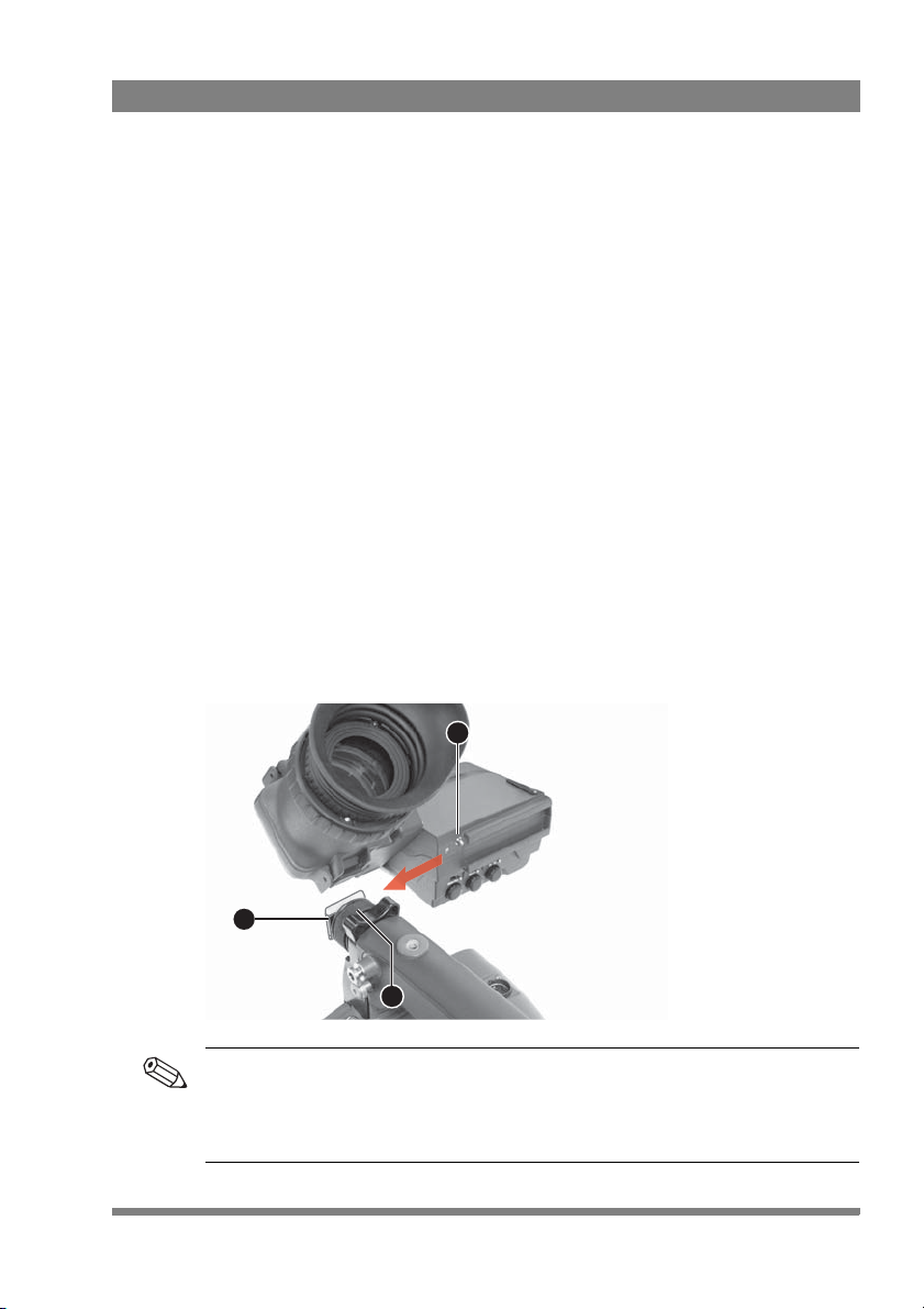
1.1 Mounting the viewfinder
To mount the viewfinder onto the camera proceed as follows:
• Loosen locking ring (2) of viewfinder support bracket (1) at the front of the
camera handgrip. (As seen from the rear of the camera, turning the locking ring
counterclockwise moves it towards the handgrip.)
• Push the locking pin (3) in and slide the viewfinder onto the viewfinder support
bracket (1).
• Tighten the locking ring (2) by turning it clockwise (as seen from rear) so that
the viewfinder is mounted securely to the support.
Chapter 1 - Installation
To improve the comfort of the skin contact when using the viewfinder, fit the eye
piece cover to the rubber eyepiece. Spare eye piece covers are available via your
Grass Valley representative.
EyeCatcher EC 270 2.7-inch Color LCD Ocular Viewfinder User’s Guide (v1.2) 9
Page 10
Chapter 1 - Installation
Tip
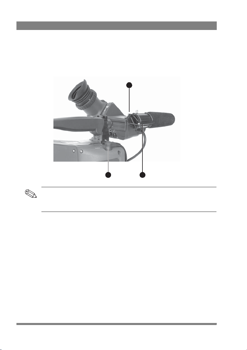
• Connect the viewfinder cable to the viewfinder connector socket (1) at the top
right of the camera.
• Attach the microphone holder (2) onto the viewfinder and secure with the
knurled screw (3).
3
1
2
Guide the viewfinder cable along the front of the camera and attach it to one of the
cable clips.
10 EyeCatcher EC 270 2.7-inch Color LCD Ocular Viewfinder User’s Guide (v1.2)
Page 11
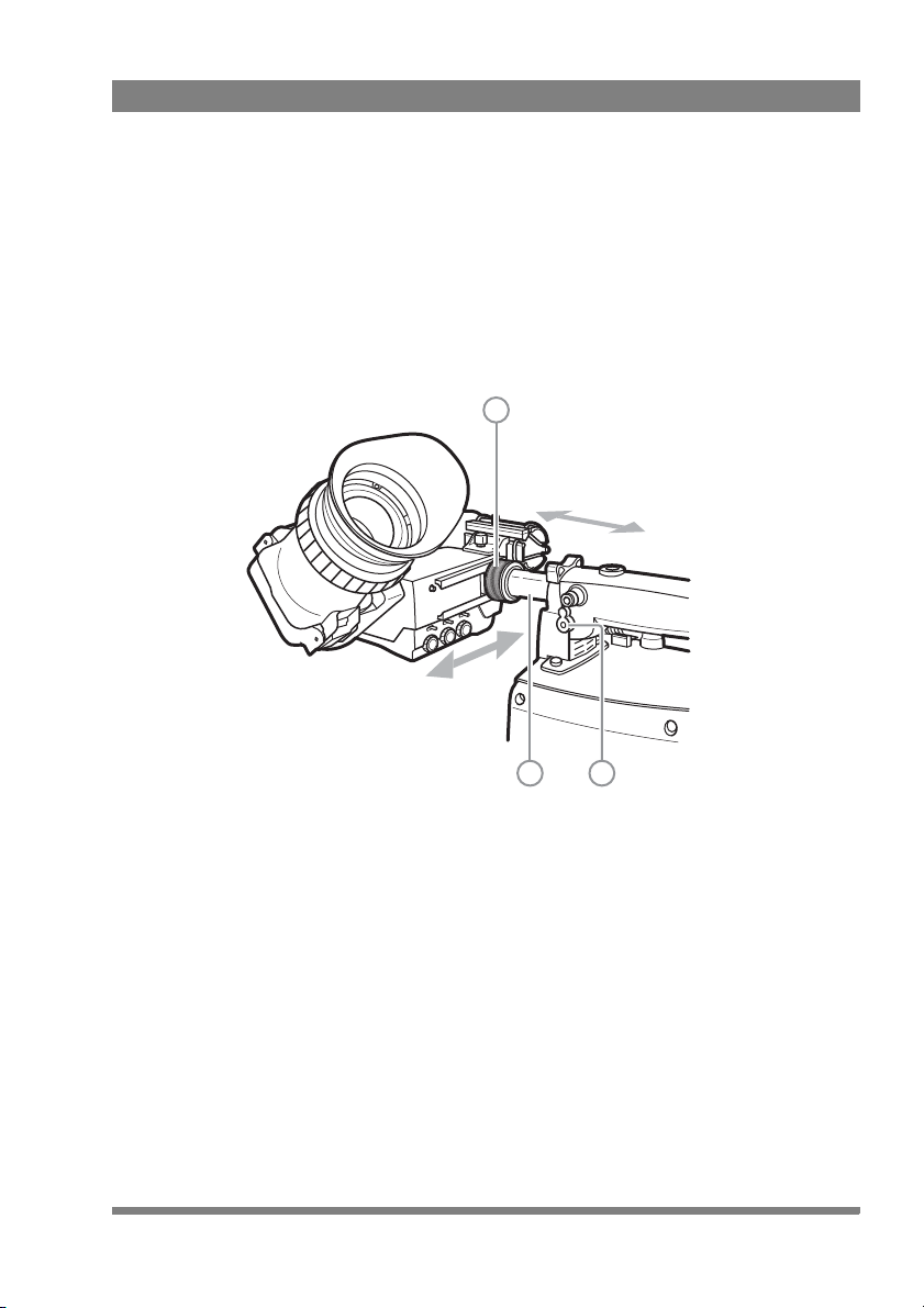
1.2 Positioning the viewfinder
The horizontal position of the viewfinder can be adjusted as follows to suit your
requirements:
• Loosen the locking ring (1). As seen from the rear of the camera, turning the
locking ring counterclockwise moves it towards the handgrip.
• Slide the viewfinder horizontally along the rail to the desired position.
• Tighten the locking ring (1) by turning clockwise.
1
Chapter 1 - Installation
2 3
The viewfinder can be positioned backwards and forwards along the camera axis:
• Loosen the support bracket round bar retaining lever (3).
• Slide the round bar (2) forwards or backwards.
• When the desired position is reached tighten the round bar retaining lever (3)
again.
EyeCatcher EC 270 2.7-inch Color LCD Ocular Viewfinder User’s Guide (v1.2) 11
Page 12

Chapter 1 - Installation
Note
4
Distance viewing
The viewfinder can also be viewed from a distance :
• Push down the bottom clip (4) below the eyepiece and swing it free of the
associated clip.
• The eyepiece can also be swung downwards; push down the top clip to
release the eyepiece and swing it downwards.
Handle the eyepiece with care when folded back—its position is not secured.
12 EyeCatcher EC 270 2.7-inch Color LCD Ocular Viewfinder User’s Guide (v1.2)
Page 13

Chapter 2
Menu-Peak On Off
TallyMode SW C
Off HiLow
321
87
4 5 6
Operation
2.1 Controls
2.1.1 Rear panel
Chapter 2 - Operation
EyeCatcher EC 270 2.7-inch Color LCD Ocular Viewfinder User’s Guide (v1.2) 13
1
Mode switch
This switch determines the function of the Menu-Peak rotary control below. Set the
Mode switch to the right (Peak) to adjust peaking level. Set the Mode switch to the
left (Menu) to use the rotary for menu navigation.
Page 14

Chapter 2 - Operation
Tip
2
3
4
5
6
7
8
Tal ly s wi tch
This switch is used to control the tally indicators at the front of the viewfinder and
the rear of the handgrip. The toggle switch has three settings: Off, Low and Hi.
When the switch is set to the Off position, the tally indicator does not light even
when the camera is On Air.
Switch C (underscan)
Set this toggle switch to On to see an underscan or scaled down (to approximately
85% of the area) picture in the viewfinder. This allows for a greater viewing distance
from the eyepiece. A blue border around the picture and the message “underscan”
appear. Set the switch to Off to return to the original picture.
Menu-Peak control
When the Mode switch (1) is set to Peak, this rotary control adjusts the peaking
level (sharpness) of the viewfinder picture.
It may be necessary to reduce peaking when the camera gain is set to high values.
When the Mode switch (1) is set to Menu, the rotary is used for navigating the
viewfinder menu. Refer to Section on page 23 for more information about the menu
and to navigate it.
Contrast control
Turn this rotary control clockwise to adjust the contrast of the viewfinder picture
according to your preferences. The range runs from 0 (low contrast) to 99 (high
contrast).
Brightness control
Turn this rotary control clockwise to adjust the brightness of the viewfinder picture
according to your preferences. The range runs from 0 (very dark) to 99 (very bright).
Dioptre adjustment ring
The dioptre of the viewfinder can be adjusted to suit your eyesight by turning the
dioptre adjustment ring. Turn to the right for negative dioptre values, turn to the left
for positive values.
Rear tally indicator
This indicator lights to indicate that the camera is On Air. This indicator has the same
function as the front tally indicator.
14 EyeCatcher EC 270 2.7-inch Color LCD Ocular Viewfinder User’s Guide (v1.2)
Page 15

2.1.2 Front panel
A
B
1 2
3
1
User button A
This user button can be assigned in the viewfinder menu.
2
User button B
This user button can be assigned in the viewfinder menu.
3
Front tally indicator
This indicator (and one at the rear of the handgrip of the camera) lights to indicate
that the camera is On Air.
Chapter 2 - Operation
EyeCatcher EC 270 2.7-inch Color LCD Ocular Viewfinder User’s Guide (v1.2) 15
Page 16

2.2 Indicators
ZoomPickMe
PickMe
Call
On AirISO
Call
On AirISO
REND
Foc
+
Gain
Bat tRet
[!]
7 8
119 10 12 13
1 2 3 4 5 6
1
2
3
4
5
2.2.1 LED indicators
Chapter 2 - Operation
Return indicator
Lights when a return video channel is switched on in the camera.
Battery power indicator
Lights if the camera input voltage is too low (when using a battery).
Call indicator
The green LED lights to attract attention when a Call signal is activated.
ISO indicator
The yellow LED lights to indicate that the camera is currently in ISO mode (yellow
On Air or Isolate)
On Air indicator
The red LED lights to indicate that the camera is currently On Air.
16 EyeCatcher EC 270 2.7-inch Color LCD Ocular Viewfinder User’s Guide (v1.2)
Page 17

Chapter 2 - Operation
7
6
PickMe indicator
This yellow LED lights when a PickMe signal is activated.
Zoom indicator
Lights when the viewfinder Zoom function is on.
8
Focus Assist indicator
Lights when the focus assist function is on (turn on in the camera menu).
9
Range Extender indicator
Lights when a range extender is selected.
10
ND filter indicator
Lights when an ND (neutral density) optical filter is selected.
11
Studio signalling indicators
Mirrored indicators from the top row (Call, ISO, On Air and PickMe) for improved
viewing range.
12
Gain indicator
Lights when gain is lower than 0 dB or higher than +3 dB
13
Non-standard indicator
The non-standard video settings indicator lights when one of the following
conditions occur:
– Exposure time is not set to the nominal value.
– Black Stretch is on.
– Extended Auto Iris is on.
– AWC (continuous automatic white balance) or FL (fluorescent) color
temperature is on.
EyeCatcher EC 270 2.7-inch Color LCD Ocular Viewfinder User’s Guide (v1.2) 17
Page 18

2.2.2 On screen indicators
55
16 Sf N:0.68m
F:1.3 5 m
+
F
5.6
60
1
2a 2b
4a 4b3
1
2a
2b
3
4a
5
Go to the camera menu to select the indicators you wish to see in the viewfinder
screen.
Zoom indicator
Indicates the percentage to which the lens has been zoomed out or in, ranging from
0 (wide) to 99 (tele). It shows 50 if the lens does not support this feature.
Chapter 2 - Operation
Iris indicator
Shows the iris opening (or F-value) of the lens. Typical range is F1.4 to F25. The
indicator shows ‘Closed’ when the lens is closed or capped.
Focus indicator
Shows the percentage of the lens focus distance. Typical range is from 0 (close-up)
to 99 (infinity).
Precision Focus (PF) indicator
Shows the Precision Focus indicator (if supported by the lens).
Filter indicator
Shows the selected optical filters (ND and FX).
Depth of Field (DOF) indicator
Shows Depth of Field of the current lens position. F = Far limit in meters, N = near
limit in meters. Ntoe: not all cameras support this feature.
18 EyeCatcher EC 270 2.7-inch Color LCD Ocular Viewfinder User’s Guide (v1.2)
Page 19

2.2.3 On screen markers
ZoomPickMe
PickMe
Call
On AirISO
Call
On AirISO
REND
Foc
+
Gain
Bat tRet
[!]
1 2 3
3
Go to the camera system menu to select the markers you wish to see in the
viewfinder screen.
1
Cadre
A dotted white line or a shaded area that shows the limits of a 4:3 (15:9 or 14:9)
picture.
Chapter 2 - Operation
2
Safe area
Encloses an area that represents 80% of the whole viewfinder picture area. This is
the minimum area seen on a TV-set.
Centre cross
Marks the centre of the picture.
EyeCatcher EC 270 2.7-inch Color LCD Ocular Viewfinder User’s Guide (v1.2) 19
Page 20

2.3 Viewfinder menu
Buttons
Config1
Diag
Config2
Color
Mono
Box
CONFIG2
EXIT
<Off>
Text
<Whit>
PkCol INDADJ
NEXT
PREV
2.3.1 Entering the menu
Many viewfinder functions can be set up in the viewfinder menu. Enter the menu as
follows:
• Make sure the mode switch on the rear panel is set to Menu (left position).
• Press the menu rotary to open the menu. A black bar with menu items
appears at the bottom of the viewfinder screen.
• Use the menu rotary to navigate to the PREV/NEXT item at the right side of
the screen.
• Press the rotary to open a list of submenus. The PREV/NEXT item is blinking.
Chapter 2 - Operation
• Turn the menu rotary to loop through the submenus. The submenus are
shown on the bottom bar.
• Press the menu rotary to leave the list and enter the selected submenu.
• Turn the menu rotary to loop through the items in the menu.
• Press to change the value of the selected item. Items with toggle values are
changed immediately. Items with select values start blinking and their value
can be changed by turning the rotary. Pressing stores the current value.
• When you are done making changes, navigate to the EXIT MENU item at the
left side of the screen. Press to leave the viewfinder menu. The black bar
disappears.
20 EyeCatcher EC 270 2.7-inch Color LCD Ocular Viewfinder User’s Guide (v1.2)
Page 21

2.3.2 Assigning user buttons
Note
EXIT
BUTTONS
<Alt>
BtnA
<Mom>
BtnB
<Box> <Mono>
FuncA FuncB
NEXT
PREV
To assign a function to a user button, proceed as follows:
• Open the viewfinder menu and navigate to the Buttons submenu as described
in the previous section.
• The Buttons submenu opens.
• Use the menu rotary to loop though the items. Press to change the value of an
item.
• The first two items (BtnA and BtnB) are used to set the switching mode for
button A and button B. Toggle between momentary (<Mom>) and alternating
(<Alt>) by pressing the rotary.
• The second two items (FuncA and FuncB) are used to assign a function to
button A and button B. Use the rotary to select a function.
• Press EXIT BUTTONS to leave the viewfinder menu.
Chapter 2 - Operation
When a user button is assigned to Call, its switching mode is automatically set to
momentary.
EyeCatcher EC 270 2.7-inch Color LCD Ocular Viewfinder User’s Guide (v1.2) 21
Page 22

2.4 Operational functions
Tip
box type line type full type
Many operational functions can be assigned to the user buttons at the front panel of
the viewfinder. Refer to “Assigning user buttons” on page 21 to read more about
assigning user buttons.
The Ext1, Ext2, Zoom and Call functions can also be assigned to user buttons on the
camera. Refer to your camera user’s guide for more details about assigning user
buttons.
2.4.1 Box
Turns the framing box on or off. This box is a very useful feature to help focussing
and framing while shooting. Three box types are available:
Chapter 2 - Operation
The box can be selected and set up in the viewfinder menu. Refer to “Box” on
page 29 for more information.
2.4.2 Mono
Switches the viewfinder to monochrome mode. Select the source (Y, R, G, B or -G)
in the viewfinder setup menu. When the camera color bar is switched on, the
viewfinder returns to color mode.
2.4.3 Ext1
Displays external video channel 1 in the viewfinder.
2.4.4 Ext2
Displays external video channel 2 in the viewfinder.
22 EyeCatcher EC 270 2.7-inch Color LCD Ocular Viewfinder User’s Guide (v1.2)
Page 23

2.4.5 Zoom
Zooms in to the center of the image for an uncropped (100%) view. The actual zoom
factor depends on the selected camera video mode. When the Zoom function is in
use, many of the viewfinder markers are switched off to improve the clarity of the
display.
The Zoom indicator in the viewfinder lights when the zoom function is active.
2.4.6 Text
Removes all text items from the viewfinder image. This includes menu and message
texts and camera indicators. Markers and cadres are not removed from the image.
Press again to restore text.
2.4.7 Call
Press the button to activate the studio Call signal. The green Call indicators on the
viewfinder light.
2.5 Camera VF functions
The following viewfinder functions are managed by the camera and are set up in the
camera system menu. Refer to your camera user’s guide for more information.
Chapter 2 - Operation
2.5.1 Viewfinder detail
The viewfinder detail function emphasizes edges in the viewfinder image, resulting
in sharpness perception. Go to the camera system menu to select the VF detail
mode and the detail level.
2.5.2 Focus Assist
The Focus Assist function adds a crawling effect in the viewfinder to objects in sharp
focus. The FOC+ indicator in the viewfinder lights when this function is active. Go to
the camera system menu to turn Focus Assist on or off.
2.5.3 Zebra
The Zebra function displays a zebra (striped) pattern in the viewfinder in areas where
highlights occur. This diagonal line pattern warns you that the area affected has risen
above a preset level of the full scale video exposure. Go to the camera system menu
to turn Zebra on or off and to set the video levels at which Zebra works.
EyeCatcher EC 270 2.7-inch Color LCD Ocular Viewfinder User’s Guide (v1.2) 23
Page 24

Chapter 2 - Operation
24 EyeCatcher EC 270 2.7-inch Color LCD Ocular Viewfinder User’s Guide (v1.2)
Page 25

Chapter 3 - Menu reference
Chapter 3
Menu reference
3.1 Menu contents
The following tables show the items and functions that can be set up in the
viewfinder menu.
3.1.1 Diag
Item Valu e ( s) Default Description
EXIT DIAG Exits the diagnostics menu.
STATUS INFO Enters the viewfinder status information
screen. Refer to “Status information” on
page 30.
—— —
LCD Temp nn C Info: shows the current LCD screen
Format <video
formats>
VF Temp nn C Info: shows the current viewfinder
PREV
↑ NEXT ↓ Selects a menu from the list.
temperature in degrees celsius.
Info: shows the current video format.
operating temperature in degrees celsius.
EyeCatcher EC 270 2.7-inch Color LCD Ocular Viewfinder User’s Guide (v1.2) 25
Page 26

Chapter 3 - Menu reference
3.1.2 Buttons
Item Val ue(s ) Default Description
EXIT BUTTONS Exits the buttons menu.
BtnA Alt, Mom Alt Selects switch mode for user button A;
BtnB Alt, Mom Alt Selects switch mode for user button B;
FuncA None, Box,
Mono, Ext1,
Ext2, Zoom,
Text, C a ll
FuncA None, Box,
Mono, Ext1,
Ext2, Zoom,
Text, C a ll
FuncC None, UScan UScan Assigns a function to user button C
PREV
↑ NEXT ↓ Selects a submenu from the list.
Box Assigns a function to user button A
Box Assigns a function to user button A
alternating or momentary.
alternating or momentary.
3.1.3 Config1
Item Val ue(s ) Default Description
EXIT CONFIG Exits the Config1 menu.
—— —
—— —
FACTORY RESET Resets the viewfinder’s settings to their
—— —
NoSignal Black, Input,
Bars
PREV
↑ NEXT ↓ Selects a submenu from the list.
26 EyeCatcher EC 270 2.7-inch Color LCD Ocular Viewfinder User’s Guide (v1.2)
Black Selects signal when no camera signal is
factory defaults. The factory defaults are
shown in the default column.
present (for example during start-up).
Page 27

Chapter 3 - Menu reference
3.1.4 Config2
Item Valu e ( s) Default Description
EXIT CONFIG Exits the Config2 menu.
Text On > Off Off Turns viewfinder on-screen text on or off
PkCol Whit, Red,
Grn, Blue, Yell,
Mgnt, Cyan
INDADJ — Push to enter the indicator adjustment
—— —
—— —
PREV
↑ NEXT ↓ Selects a menu from the list.
Whit Selects the color of the viewfinder peaking
Indicator adjustment
Item Valu e ( s) Default Description
EXIT INDADJ Exits the indicator adjustment menu. The
IndLvl Low, Med,
High
RearTlly Ena, Dis Ena Enables or disables the viewfinder rear tally
—— —
—— —
—— —
—— —
Med Selects the indicator level for the
(this is a camera function).
indication (white, red, green, blue, yellow,
magenta, cyan).
submenu; see below.
set indicator level is stored.
viewfinder LED indicators.
indicator.
EyeCatcher EC 270 2.7-inch Color LCD Ocular Viewfinder User’s Guide (v1.2) 27
Page 28

Chapter 3 - Menu reference
3.1.5 Color
Item Val ue(s ) Default Description
EXIT COLOR Exits the color menu.
—— —
—— —
—— —
Satur 0..99 50 Sets the color saturation level.
ColTemp 3200K..9500K 6500K Sets the viewfinder color temperature.
PREV
↑ NEXT ↓ Selects a menu from the list.
3.1.6 Mono
Item Val ue(s ) Default Description
EXIT MONO Exits the monochrome menu.
Mono On > Off Off Turns monochrome mode on or off (this is a
Source Y, R, G, B, -G Y Selects a signal source for the
—— —
—— —
—— —
PREV
↑ NEXT ↓ Selects a menu from the list.
camera system function).
monochrome image when mono mode is
on (this is a camera function).
28 EyeCatcher EC 270 2.7-inch Color LCD Ocular Viewfinder User’s Guide (v1.2)
Page 29

Chapter 3 - Menu reference
3.1.7 Box
Item Valu e ( s) Default Description
EXIT BOX Exits the box menu.
Box Off, Box, Line,
Color Whit, Red,
Side T/B > L/R T/B Selects the side of the box to be adjusted:
Top 0..99 24 Sets the top position of the box.
Bottom 0..99 73 Sets the bottom position of the box.
Left 0..99 24 Sets the left position of the box.
Right 0..99 74 Sets the right position of the box.
PREV
↑ NEXT ↓ Selects a menu from the list.
Full
Grn, Blue, Yell,
Mgnt, Cyan
Off Selects the box type.
Whit Selects the line color of the box (white, red,
green, blue, yellow, magenta, cyan).
T/B = Top/Bottom; L/R = Left/Right
EyeCatcher EC 270 2.7-inch Color LCD Ocular Viewfinder User’s Guide (v1.2) 29
Page 30

3.2 Status information
EXIT
Viewfinder Status Information
Type: LDKxxxx
Package: 12NC: 3922 407 xxxxx vxx.xx Date: xx/xx/xx
Firmware: 12NC: 3922 407 xxxxx vxx.xx Date: xx/xx/xx
Main Brd: 12NC: 3922 406 xxxxx St: xx Date: xx/xx/xx
PID: xxxxx
Appl.Sw: 12NC: 3922 407 xxxxx vxx.xx Date: xx/xx/xx
Conf.Sw: 12NC: 3922 407 xxxxx vxx.xx Date: xx/xx/xx
PID: xxxxxx
The status information screen shows information about the viewfinder’s internal
hard- and software components. This information can be useful when contacting
Grass Valley service support. Press EXIT to leave this screen.
Chapter 3 - Menu reference
30 EyeCatcher EC 270 2.7-inch Color LCD Ocular Viewfinder User’s Guide (v1.2)
Page 31

Chapter 4
Specifications
4.1 Technical specifications
4.1.1 General
Power supply +10.5 VDC to 17 VDC (supplied by the camera)
Operating temperatures -20 to +45 °C (-4 to +113 °F)
Storage temperatures -25 to +70 °C (-13 to +158 °F)
Power consumption (typ.) 3.5 W (supplied by the camera)
Dimensions (W x H x D) 248 x 76 x 219 mm (9.8 x 3.0 x 8.6 in)
Weight (approx.) 820 g (1.8 lbs)
Input signals Y, Pr, Pb
Chapter 4 - Specifications
4.1.2 Screen
Diagonal size 2.7 in (68 mm)
Color depth 16.7 million colors (8 bit color)
Total display area 960 (H) x 540 (V) pixels (QHD resolution)
Response rate 14 ms
Eyepiece adjustment range +1 to -3 dioptres
Pixel pitch 0.0615 x 0.0615 mm
Luminance (typ.) 300 Cd/m
Contrast ratio (typ.) 500:1
EyeCatcher EC 270 2.7-inch Color LCD Ocular Viewfinder User’s Guide (v1.2) 31
2
Page 32

4.1.3 Dimensions
109 mm97 mm
76 m m119 m m
219 mm
Chapter 4 - Specifications
4.1.4 Accessories
• Microphone holder (included)
32 EyeCatcher EC 270 2.7-inch Color LCD Ocular Viewfinder User’s Guide (v1.2)
Page 33

4.2 Connectors
Pin Description
1 Not connected
2 Not connected
3 Not connected
4 INTN-D (I
2
C interface)
5 Not connected
6 Not connected
7 VF video return
8 SDA-D (I
2
C interface)
9 SCL-D (I
2
C interface)
10 Not connected
Pin Description
11 GND
12 VF video
13 Pb VF video return
14 Pr VF video return
15 Not connected
16 +Batt (10.5 to 17 VDC)
17 -Batt (10.5 to 17 VDC)
18 Pb VF video
19 Pr VF video
20 Shield
20-pin male viewfinder connector, moulded to the viewfinder cable
(manufacturer code: Hirose HR12-14LA20P)
20
1
16
5
4.2.1 Viewfinder lead connector
Chapter 4 - Specifications
EyeCatcher EC 270 2.7-inch Color LCD Ocular Viewfinder User’s Guide (v1.2) 33
Page 34

Chapter 4 - Specifications
34 EyeCatcher EC 270 2.7-inch Color LCD Ocular Viewfinder User’s Guide (v1.2)
Page 35

EyeCatcher EC 270 2.7-inch Color LCD Ocular Viewfinder User’s Guide (v1.2) 35
Page 36

Copyright Grass Valley Nederland B.V.
 Loading...