

Page 1

DVCPRO UPGRADE
Installation Manual
071-0516-02
MARCH 2000
PROFILE Family
VIDEO FILE SERVERS
Page 2

Copyright Copyright © 2000 Grass Valley Group Inc. All rights reserved. Printed in the United
States of America.
This do cument m ay not be copied i n whole o r in part , or other wise repr oduced
except as sp ec ifi ca ll y permit ted under U. S. copyri gh t law , wi th out the prior writ ten
consent of Grass Valley Group Inc., P.O. Box 59900, Nevada City, California
95959-7900
Trademarks Grass Valley, GRASS VALLEY GROUP, Profile and Profile XP are either
registe red trad em arks or trad ema rk s of Gras s Va ll ey Gr oup in the Uni ted Stat es
and/or other countries. Other trademarks used in this document are either
registered trademarks or trademarks of the manufacturers or vendors of the
associated products. Grass Valley Group products are covered by U.S. and foreign
patents, issued and pending. Additional infor m ation regarding
Grass Valley Grou p's tradem arks and oth er propri etary right s may be fou nd at
www.grassvalleygroup.com.
Disclaimer Product options and specifications subject to change without notice. The
informati on in this manual is furnished fo r informat ional use only, is subject to
chang e witho ut notic e, an d shou ld not b e cons trued as a com mitme nt by G rass
Valley Group. Grass Valley Group as sumes no res ponsibility or liability f or any
errors or inaccu racies that may appear in this publication.
U.S. Government
Restricted Rights
Legend
Revision Status
Use, duplication, or disclosure by the United States Government is subject to
restrictions as set forth in s ubparagraph (c )(1)(ii) of t he Rights in Tech nical Data
and Comp ut er So ftwa re clau se at DFA RS 25 2.277 -7 013 or in su bpara gra ph c(1 )
and (2) of the Comm ercial Co mputer So ftware Re stricte d Rights cl ause at FAR
52.227-19, as applicable. Manufacturer is Grass Valley Group Inc., P.O. Box
59900, Nevada City, California 95959-7900 U.S.A.
Rev Date Description
March, 1999 Original issue. Manual Part Number 071-0516-00.
October, 1999 Revised to include two-codec board.
Manual Part Numbe r 071-0516-01.
March, 2000 Revised to include DVCPRO 50.
Manual Part Numbe r 071-0516-02.
Page 3

Contents
Grass Valley Group Product Support ............................................................ ............ .. 5
General Safe ty Su mm ary .......................... ........................ ................. ....................... .. 6
Certifications and Compliances................................................................................... 9
Before You Begin ........................................................................................................ 11
Installation Summary.... ................. ....................... ........................ ....................... 12
Upgrading Pro file System Software................................. ................. ........... 12
Updating Profile Circuit Board Firmware.. .................................................... 12
Master and Slave EDR Memory Requirements........................................... 13
Installing Additional Upgrade Kits............................................ ....... ....... ............ .. 14
Kit Contents......................................................................................................... 14
Tools Required............... ........................ ........................ ................ ..................... 14
Electro sta tic Precaution s..... ........................ ........................ ....................... ......... 15
DVCPRO Operation al Consideration s...................... ................ ........................ ........... 16
DVCPRO System Timing Considerations............................................................ 16
Restrictions When Using JPEG and DVCPRO.................................................... 17
Removing the Profi le Unit from the Rack ................... ................. ....................... ......... 18
Removing the Chassis Covers.................................................................................... 20
Removing the Board Hold-down Brackets .................................................................. 22
Installing the DVCPRO Boards.................................................................................... 24
Installing Boards in an Option DV or PDR400 Unit ........................ ....... .......... .... 26
Installing Boards in a non-Option DV Unit ........................................................... 30
Installing Boards in an Early PDR200 Unit.................. .......... .. ....... ....... .......... .... 32
Removing Circui t Bo a r d s ...... ................ ................. ................ ..................... 32
Reinstalling the Boards ............................................................................... 34
Reassemblin g the Pr o file Chassis ............... ................ ........................ ................. ...... 36
Verifyi ng In stallation............... ........................ ........................ ....................... .............. 38
Using Configuration Manager to Verify Installation.............................................. 38
Performing Functional Tests................................................................................ 39
Updating an Emergency Repair Disk .......................................................................... 40
Connecting Audio Clock and Sharcnet Cables............................................................ 41
ASPB Audio Clock and Sha rcn e t Cabling Examples............. ................ .............. 42
Two Serial Digital I/O Boards and One ASPB ........................... .................. 42
Three Seria l Di gi tal I/O Boards and Two ASPB s.................. ....................... 44
Two Analog Composite I/O Boards and One ASPB.................................... 46
Three Analog I/O Boards and Two ASPBs... ................. ........................ ...... 48
Detailed Expl a n at ion Of ASPB Cabling............................ ................. .................. 50
Audio Clock Cabling..................................................................................... 50
Sharcnet Cabling ......................................................................................... 52
DVCPRO Board Installation 3
Page 4

Board Location Guide................................ ........................ ........................ .................. 53
Video Router to Motherboard Relationship.......................................................... 53
Video Router I/O Connections ............................................................................ 54
Selecting a Board Location.................................................................................. 56
Troubleshooting.................................. ................... .............. ................... ............ ......... 58
Troubleshooting Aid............................................................................................. 58
Figures
1 Removing the Profile unit from the instrument rack........................................ 19
2 Removing the fron t a n d rea r chassis covers .................. ................ ................ 21
3 Removing the circuit board hold-down brackets............................................. 23
4 Screw locations for board mounting board bracket ........................................ 27
5 Reconnect the SCSI cables............................................................................ 28
6 Installing the five-slotted PCI Interconnect board .................................. ......... 29
7 Stick-on label location..................................................................................... 37
8 Configuration Manager showing DVCPRO boards ......................................... 39
9 ASPB cabling with two Seri a l Digital I/O board s a nd one ASPB.................... 43
10 ASPB cabling with three Serial Digital I/O boards and two ASPBs................ 45
11 ASPB cabling with two Analog Composite I/O boards and one ASPB........... 47
12 ASPB cabling with three Analog Composite I/O boards and two ASPBs....... 49
13 Audio clock g r o ups an d refe r e n ce sele ction.......................... ................ ......... 50
Tables
1 DVCPRO upgrade kit nomencla ture .............................................................. 11
2 List of kit cont ents ........................ ................. ........................ ....................... .. 14
3 Board locat ion s .................................... ................ ........................ .................. 24
4 Summary of board installation procedures .................................................... 25
5 Cabling for two Serial Digital I/O boards and one ASPB ............................... 42
6 Cabling for three Serial Digital I/O boards and two ASPBs ........................... 44
7 Cabling for two Analog Composite I/O boards and one ASPB ...................... 46
8 Cabling for three Serial Digital I/O boards and two ASPBs ........................... 48
9 Board location chart ...................................................................................... 55
10 Board I/O requirements and restrictions
for a PDR 200 with DVCPRO boards ................................................. 57
11 PDR200 DVCPRO upgrade procedure troubleshooting table ....................... 58
4 DVCPRO Board Installation
Page 5

Grass Valley Group Product Support
You can get technical assistance, check on the stat us of problems, or
report new proble ms by contacting our Product Support Grou p.
United States and Canada
Monday–Friday 5:30AM–5:00PM Pa cific Ti me
(800) 547-8949
Europe
Monday–Friday 9:00AM–5:30PM
France 01 69 86 83 47 United Ki ngdom 01628 405830
Germany 0221 9477 446 Other +44 1628 405840
Italy 02 25086606
Asia and South America
Australia
- from overseas
Beijing 86-10-62351230
Brazil 55-11-3741-8422 Taiwan 886-2-27571571
Hong Kong 852-25856655
02-9888 0100
61-2-9888 0100
ext. 711
Japan 81-3-3448-3111
Korea 82-2-528-5299
Mexico 52-5-666-6333
Singapore 65-356-3900
World Wide
24-hour Emergency Hotline (530) 478-4148 (Contract and warranty
customers)
W orld Wide Web http://www.grassvalleygroup.com/support/
FTP Site ftp.grassvalleygroup.com
Users Group profile-users@grassvalleygroup.com
DVCPRO Upgrade Installation 5
Page 6
General Safety Summary
General Safety Summary
!
WARNING: These instructions are for use by qualified
service personnel only. To avoid personal injury, do not
perform any servicing unless you are qualifie d to do so.
Refer to all safety summaries before performing service.
Review the following safety precautions to avoid personal
injury and prevent damage to this product or any products
connected to it.
While using this product, you may need to a ccess other parts
of the system. Read the general safety summary in other
system manuals for warnings and cautions related to
operating the system.
Injury Precautions
Do Not Service
Alone
Disconnect Power To avoid electric shock while servi cing, disconne ct the main
Use Care W h en
Ser vicing W ith
Power On
Do not perform inte rnal se rvice or a dju stment of this product
unless another person capable of render ing first aid and
resuscitation is pres ent.
power by means of the power cord.
Dangerous voltages or currents may exist in this product.
Disconnect power and remove battery (if applicable) before
removing protective panels, soldering, or replacing
components.
Avoid Exposed
Circuitry
Do Not Operate
Without Product
Covers in Place
6 DVCPRO Upgrade Installation
To avoid injury while servicing, remove jewelry such as
rings, watches, and other metallic objects. Do not touch
exposed connections a nd compone nts when p ower is pres ent.
To avoid electric shock or fire hazard, do not operate this
product with covers or panels removed.
Page 7

Product Damage Precautions
Do Not Operate in
Wet/Damp
Conditions
Do Not Opera te i n an
Explosive
Atmosphere
To avoid electric shock, do not op erate this pr oduct in we t or
damp conditions.
To avoid injury or fire hazard, do not operate this product in
an explosive atmosphere .
Product Damage Precautions
Use the Proper
Voltage Setting
Provide Proper
Ventilation
Do Not O p er ate If
You Suspect
Product Failures
Ensure that the line selec tor is in the proper position for the
power source before applying power.
Prevent product overhea ting by providing proper vent ilation.
If you suspect there is damage to this product, have it
inspected by qualifie d servic e personnel.
Safety Terms and Symbols
Terms in This
Manual
These terms may appear in this manual:
!
!
WARNING: Warning statements identify conditions or
practices that can result in personal injury or loss of life.
CAUTION: Caution statements identify conditions or
practices tha t can result in damage to the equipment or other
property.
DVCPRO Upgrade Installation 7
Page 8
General Safety Summary
Terms on the
Product
Symbols on the
Product
!
These terms may appear on the product:
DANGER indicates a personal injury hazard imme diately
accessible as you read the marking.
WARNING indicates a personal injury hazard not
immediately accessible as you read the marking.
CAUTION indicates a hazard to property, including the
product.
The following symbols may appear on the product:
DANGER high voltage
Protective ground (eart h) ter minal
ATTENTION – refer to manual
8 DVCPRO Upgrade Installation
Page 9

Certifications and Compliances
Certifications and Compliances
FCC Emission
Control
Canadian EMC
Notice of
Compliance
This equipment has bee n tested and found to co mply with the
limits for a Class A digital de vice, pursuant to Part 15 of the
FCC Rules. These limits are designed to provide reasonable
protection against ha rmful interference when the equipment
is operated in a comm ercial environ m en t . This eq uip m en t
generates, uses, and can radiate radio frequency energy and,
if not installed and used in accordance with this installation
manual, may cause harmful interf erence to radio
communications. Oper ation of t his equipment in a residential
area is lik ely to cause harmful interference in which case the
user will be requi red t o corr ect the interference at his or her
own expense. Changes or modifications not expressly
approved by Grass Valley Group can affect emission
compliance and could void the user’s author ity to operate this
equipment.
This digital appar atus does not exceed the Class A limits for
radio noise emissions from a digital apparatus set out in the
Radio Interferenc e Regulations of the Canadian Department
of Communications.
Le présent appareil num érique n’émet pas de bruit s
radioélectriques dépassant les li mites applicables aux appareils
numériques de la classe A préscrites dans le Règlement sur le
brouillage radioélectrique édicté par le ministère des
Communications du Canada.
EN55022 Class A
Warning
For products that comply with Class A. In a domestic
environment, this product may cause radio interference, in
which case the user may be required to take adequate
measures.
DVCPRO Upgrade Installation 9
Page 10
Certifications and Compliances
Certification
Category Standard
Safety Designed /te sted for co m p liance w it h:
UL1950 – Safe ty of Info rmation Technolo gy Equipme nt, inclu ding Ele ctrica l
Business Equipment (Thir d Edition, 1995)
IEC 950 – Safety of Information Technology Equipment, including
Electrical Business Equipment (Second edition, 1991)
CAN/CSA C22.2, No. 950-95 – Safety of Information Tec hnology
Equipment , including Electrical Busin ess Equipment
EN60950 – Safety of Information Tec hnology Equipment, including
Electrical Business E quipment (includes Appendix ZB)
10 DVCPRO Upgrade Installation
Page 11

Before You Begin
NOTE: Profile System S oftware version 3.2 or higher must be installe d before
you install any DVCPRO boards. For more information, see “Upgrading
Profile System Software” on page 12.
This installation manual explains how to install the DVCPRO boards in the
PDR200 Video File Server. Included are procedure s for installing the DVCPRO
boards in both a DVCPRO-ready (Option DV) PDR200 and a
non-DVCPRO-ready PDR200.
There are two DVCPRO upgrade kits for the PDR200 as shown in Table 1.
The PDFDV04 upgrade kit inc ludes o ne DVCPRO CODEC board whi ch featu res
four DVCPRO 25 codecs. Each codec can be used for DVCPRO 25 record and
playback. Each pair of DVCPRO 25 codecs can be u sed as a single DVCPRO 50
codec for DVCPRO 50 record and playback.
The PDFDV02 upgrade kit inc ludes o ne DVCPRO CODEC board whi ch featu res
two DVCPRO 25 Codecs. Each codec can be used for DVCPRO 25 record and
playback. The pair of DVCPRO 25 codecs can be used as a single DVCPRO 50
codec for DVCPRO 50 record and playback.
Before You Begin
To install an additiona l two-codec DVCPRO CODEC board in a PDR400, you
can use the instru cti ons fo r ins tal ling boar d s in a DVCPRO-rea dy s ystem . The
PDFDV02 two-codec board must be installe d in slot J12.
NOTE: Grass Valley Group s upports a to tal of six DVCPRO 25 codecs i n th e
Profile syste m. Gras s Valley Group doe s not support the DVCPRO B oards in
systems with MPEG boards installed.
Table 1. DVCPRO upgrade kit nomen clature
Kit Nomenclature DVCPRO Board Features
PDFDV04 DVCPRO Code c 4 DVCPRO 25 Codecs
PDFDV02 DVCPRO Codec 2 DVCPRO 25 Codecs
DVCPRO Upgrade Installation 11
Page 12

DVCPRO Board Installation
Installation Summary
The following l ists the tasks for c ompleting the DVCPRO upgrade . You may not
have to perform all the tasks listed, depending on your unit’s serial number and
previous upgrades, if any, you have performed.
To install the DVCPRO upgrade you must:
1. Upgrade Profile system software to version 3.2 or higher.
2. Update Profile circuit board firmware.
3. Install additional Master and Slave EDR board memory if required.
4. Install the DVCPRO board and verify perfor mance.
5. Update Windows NT 4.0 Emergency Repair Disk.
The following sec tions give more information on completing each of these tasks.
The procedure starts on page 18.
Upgrading Profile System Software
The Profile system soft ware installed in the PDR200 must be version 3.2 or higher
to support the DVCPRO boards. This software should have been ordered and
received along with this DVCPRO upgrade kit. To chec k the softwa re version
installed in your Prof ile sys tem, open the Vrd Panel applic ation a nd choose
About VdrPanel
displayed wi ndow. I f you do not ha ve s oftware v ersion 3. 2 or hi gher, c ont act your
Grass Valley Group represen tative.
Help |
. The software version is listed as the product version in the
NOTE: Complete software upgrade instr uctions are located in the Profile
System Software Release Notes inclu ded with your software kit. Be sure to
thoroughly read the release notes before upgrading your Profile system
software.
Updating Profile Circuit Board Firmware
After you install the corr ect version of Profile system software, you may need to
update the firmware of some Profile circuit boards. Profile system software
provides the software utilities for doing this. The procedures are described in the
release notes and in the Profile Utilities chapter of the Profile Family User
Manual.
12 DVCPRO Upgrade Installation
Page 13

Installation Summary
Master and Slave EDR Memory Requirements
The DVCPRO upgrade requires 64-megabyte s of memory on both the Master and
the Slave Enhanced Disk Recorder (EDR) Boards. If you order ed your PDR200
recently, the Master and Slave EDR boards already have 64 megabytes of
memory. If you have an earlier model (seri al number B029999 or below), you
must install additional memo ry if you have not done s o already. To see the amount
of memory you have on the Master and Slave EDR boards, check in the Profile
Log for messages regarding memory size. To vie w the Profile Log, double click
the Profile Log shortcut on the Windows NT 4.0 desktop . If your Profile system
has been running for a long time, the text regar ding memory size may have
scrolled out of th e Profile Log . In this ca se, you can re boot the Profi le sy stem and
check the Profile Log again.
If your system does not have the required memory, you will need two service
kits— one kit for the Master and one for the Slave—each with two 32-megabyte
SIMMs.
If you normally opera te with a large video file system (greater than 2500 clips as
might be the case in commercial cache applications) Grass Valley Group
recommends that you have 32 megabytes of local memory installed for the i960
real-time system (RTS) proc essor on the Master EDR board to enhance system
performance. If you ordered your PDR200 recently, you already have
32 megabytes of i960 local memory i nstalle d. If you ha ve an earli er model (ser ial
number B039999 or below), you should install ad ditional memory if you have not
done so already. Check the Profile Log for messages r egarding RTS memory size.
If your system does not have 32-megabytes of real time system (RTS) processor
memory, you will need one kit for this upgrade, c ontaining one 32-megabyte
SIMM, replacing the existing 16-megabyte SIMM.
NOTE: You should have obtained service kits for these memor y upgrades at
the same time yo u received the DV CPR O up grad e k it. If you ne ed to insta l l
these memory upgrades, do so before installing the DVCPRO boards. Refer
to the procedures in the memory kits for speci fic instructions. If for some
reason you have not obtained the kits, contact your Grass Valley Group
representative.
DVCPRO Upgrade Installation 13
Page 14
DVCPRO Board Installation
Installing Additional Upgrade Kits
If you ordered both DVCPRO upgrade kits (PDFDV04 and PDFDV02), you can
install them both at the same time using the procedur es in this manual.
If you have ordered other upgrade kits, such as a video I/O board upgrade or the
Audio Signal Proces sor Board (ASPB) upgrade, you can install them at the sa me
time while the Prof ile ch assis is open .
Kit Contents
The DVCPRO upgrade kit includes all the items listed in Table 2
Table 2. List of kit co ntents
Qty. Item
1 D V C PRO Board (two or four codecs)
1 5 Slot PCI Interconnect
1 Board i d entifica tion label st rip
4 Sharcnet cable
4 Replacement tie wraps for bundling cables
1 Disposable ESD ground strap
5 Anti-static bags for board storage
1 This Installation Manual
Tools Required
Tools required to install the board are (not supplied in this kit):
• A Torx tool with T10 and T15 tips.
14 DVCPRO Upgrade Installation
Page 15

Electrostatic Precautions
CAUTION: All Profile system circuit boards h ave components that are h ighly
!
!
sensitive to electrostatic discharge (ESD). To protect these components from
damage and to maintain product reliability, take the following precaut ions
when handling the circuit board:
• Handle all circuit boards in a static- prote cted area capable of controlling
static charge on conductiv e materials, people, and nonconductive
materials. Stat ic-protect ed areas inclu de nonstatic table tops a nd nonstatic
floor mats.
• While out of the chassis, place boards in the ESD static-s hielded bags
(provided with this kit) until you install them.
• Wear ESD grounding straps when handling boards outside of their ESD
static-shielded bags.
• H andle the circuit boards only by the ed ges and avoid touching the printed
wires on the back of the circuit board as much as possible.
Electrostatic Precautions
DVCPRO Upgrade Installation 15
Page 16

DVCPRO Board Installation
DVCPRO Operational Considerations
This section describes DVCPRO operational issues which you need to consider
when placing your Profile syst em back into ope ration after completing the
upgrade. These include:
• DVCPRO System Timing Considerations
• Restrictions When Using JPEG and DVCPRO
DVCPRO System Timing Considerations
The DVCPRO 25 co decs used in Pr ofile syst ems are a ctually pai rs of codecs.
Because of t his paired codec archite cture, so me restric tions apply to the DVCPRO
codecs which require the following system timing limitations:
1. You must supply a Reference In signal to the Profile system.
2. All video signals that you want to record with a DVCPRO codec must be
synchronous with the Reference In signal.
3. If you want to use the DVCPRO 2 5 codecs a s indepe ndent codecs, all of your
video inputs must be auto-timed to the Refer ence input. In Configuration
Manager, se le ct Enab l e Au to-T im ing fo r each i npu t. Y ou must en s ure that
each input actual ly auto-tim es by checking that the Auto-Tim ed indic ator in
the Video Input dialog box is lit. Refer to “Using the Profile Configuration
Manager” in the Profile Family User Manual for more information on
Auto-Timing.
4. If you are unable to auto-time an input , or if you wish to use the DVCPRO
codecs for BVW Insert/Edit operations , you may onl y use one of the codec s
from each pair, DVCPRO25 #1, DVCPRO25 #3, and DVCPRO25 #5. Note
that the second DVCPRO25 codec from each pair must not be used
(DVCPRO25 #2, DVCPRO25 #4, and DVCPRO25 #6).
16 DVCPRO Upgrade Installation
Page 17

Restrictions When Using JPEG and DVCPRO
Restrictions When Using JPEG and DVCPRO
After completing the DVCPRO upgrade, the JPEG Codecs on the Master and
Slave Enhan ce d Di sk Re co rder boards remai n availab l e as res ou rces for
record/play channels or for transcoding clips between JPEG and DVCPRO. In
some configurati ons, the operation of one of the JPEG codecs may be restr icted as
follows:
- When both JPEG #2 and DVCPRO25 #4 are used, they must both be
connected to the sa me video input vi a the internal vi deo crosspoint r outer,
otherwise, the wrong video input may be recorded.
When you are using DVCPRO25 #4 and you need to configure a JPEG channel,
use one of the other three JPEG codecs available to avoid any restrictions.
DVCPRO Upgrade Installation 17
Page 18
DVCPRO Board Installation
Removing the Profile Unit from the Rack
You can inst all the boa rds with the Profi le chassis fully e xtended on the rack s lides
if the instrument rack is adequately anchored to prevent tipping, and if the re is
sufficient slac k in the cabl es connected to the rear panel to allow the chassis to
fully extend on the slides. If you decide to keep the c hassis in the rack during the
installati on, it is a good idea to loosen any screws that need to be removed from
the back of the Profile unit before s lidi ng it forwa rd on the r acks. You wi ll have to
read the appropriate installation procedure first to determine which screws must
be loosened.
WARNING: Unless the instrument rack is adequately anchored, the rack
!
could tip when the chassis is extended on the rack slides. To avoid possible
injury, make sure the rack is secured firmly before extending the Profile
chassis on the rack slides.
If you cannot or do not want to install DVCPRO boards with the Profile chassis
extended on the rack slide s, use the following procedure to remove the unit f r om
the instrument rack:
1. Remove all cables connected to the rear of the Profile unit. If you have not
done so already, label all cable s before removing them to make it easier to
reconnect them later.
2. Loosen the front-panel r etaining screw (Êin Figure 1).
3. Grasp the handles and pull the chassis out (Ë in Figure 1) until the slides
latch. This holds the Profile chassis firmly in position.
WARNING: To avoid personal injury, at least two people must remove the
!
Profile chassis from the rack—it is too heavy for one person to lift.
4. With a person on each side of the unit, press in both track stop latch buttons
(Ì in Figure 1) and care fully s lide the Prof ile c hassis free of the tr acks (Í in
Figure 1).
5. Place the Pro f ile u nit on an ESD -p rot ect e d wo rk surface.
NOTE: Now is probably a good time to clean the front filter of your Profile
unit. With a strong vacuum, you can clean the filter through the front cover.
18 DVCPRO Upgrade Installation
Page 19

4
3
Stop latch button
(each side)
Removing the Profile Unit from the Rack
1
2
0169-2
Figure 1. Removing the Profile uni t from the i nstrument rack
DVCPRO Upgrade Installation 19
Page 20

DVCPRO Board Installation
Removing the Chassis Covers
To remove th e chass is covers from the Pro file u nit:
NOTE:
rear
1. Turn Profile system power off and remove the power cord .
2. Loosen the fr ont pa nel r etaining sc rew and pull the cha ssis out f rom the rack
3.
NOTE: Store the chassis screws in a cont ainer so that you do not lose them.
They must all be reinstalled as they are require d to meet the EMI
specificati ons for the video file server.
4. Use the Torx tool with the T10 tip to remove the rear chassis cover (
The front chassis cover must be removed first because it overlaps the
cover.
until the slide secti ons latch. If the rack is not anchored firmly, remove the
chassis from the rack (see the instructions under “Removing the Profile Unit
from the Rack” on page 18).
Use the Torx tool with the T10 tip to remove the top screws from the front
chassis cover (Ê
side screws . Set cover aside.
Figure 2). Set the cover aside.
in Figure 2) and use the T15 tip to remove the pan-headed
in
Ë
20 DVCPRO Upgrade Installation
Page 21

9675-9
Removing the Chassis Covers
2
1
Figure 2. Removing the front and rear chassis covers
DVCPRO Upgrade Installation 21
Page 22

DVCPRO Board Installation
Removing the Board Hold-down Brackets
There are two hold-down brackets loc a ted in the circuit board area of the chassis
that must be removed in order to install other boards.
To remove the board hold-down brackets:
1. Use the Torx tool with the T10 tip to remove the exterio r screw (Êin
Figure 3) that secures the rear board hold-down bracket.
2. Lift the bracket (
3. Use the Torx tool with the T10 tip to remove the interior scre w (Ìin
Figure 3) that secures the front board hold-down bracket.
4. Lift the bracket (
NOTE: Now would be a good time to do the memory upgrades mentioned in
“Master and Slave EDR Memory Requirements” on page 13.
in Figure 3) up and out of the chassis and set it aside.
Ë
in Figure 3) up and out of the chassis and set it aside.
Í
22 DVCPRO Upgrade Installation
Page 23

Removing the Board Hold-down Brackets
3
4
2
9675-2
Figure 3. Removing the circuit board hold-down brac kets
1
DVCPRO Upgrade Installation 23
Page 24

DVCPRO Board Installation
Installing the DVCPRO Boards
This sectio n describes how to install the DVCPRO boards in the PDR200. In this
procedure, you will be instructed to remove the three-slotted PCI Interconnect
board and replace it with the five- slotted board provided in this upgrade kit. The
center slot on the five-slotted PCI board must be aligned with the Master EDR
board in s lot J10. All other boards conne cting to the PCI Interconnect board must
be installed in the board slot s shown in Table 3.
Table 3. Board locations
Board Required
Board Slots
Slave EDR J8
Fibre Cha nnel (if installed) J9
Master EDR J10
DVCPRO CODEC (PDFDV04) J11
DVCPRO CODEC (PDFDV02) J12
If you have an Option DV (DVCPRO-ready) PDR200, the circuit boards are
already in the required boa rd slots. All you have to do is install the DVCPRO
boards. Other PDR200 configurations r equire moving boards to other slot
locations to free up the required slots. For this reason, there are three procedures
in this section which give step by step instructions for all the possible PDR200
configurations.
Refer to Table 4 to determine which procedure you should follow, then proceed.
24 DVCPRO Upgrade Installation
Page 25

Installing the DVCPRO Boards
Table 4. Summary of board in stallation procedures
Procedure Serial Number Page
Installi ng Boards in an Option D V or PDR400 Unit
(or PDR400 systems with one four-codec board)
Installing Boards in a non-Option DV Unit B030000 or above 30
Installi ng Boards in an Early PD R200 Unit B029999 or below 32
B042553 or above
(B010000 for PDR400)
26
DVCPRO Upgrade Installation 25
Page 26

DVCPRO Board Installation
Installing Boards in an Option DV or PDR400 Unit
Follow these instructions to install the DVCPRO boards in a DVCPRO-ready
PDR200 (Option DV), or in a PDR400 system.
1. Remove the three-slotted (five-slotted in PDR400) PCI Interconnect board
and remove all cables connected to Profile boards, such as SCSI, Sharcnet,
or audio clock cables (look at Figure 9 on page 43 if you need help
identifying the Shar cnet and audio clock cables). Label each cable bef ore
removing it and draw a simple diagram to make it easier to reconnect the
cables later. Remove any cable tie wraps, if necessary.
NOTE: Be certain to label the SCSI cables before removing th em so that you
can reconnect them properly. If the A and C SCSI cables are reversed, the file
system will appear to be corrupted.
2. Remove the board bracket for slot J11 if you are installing a four-codec
DVCPRO CODEC board. If you are installing the two-codec DVCPRO
CODEC board, remove the board bracket for J12.
CAUTION: Forcing the board into the slot may result in bent connectors on
!
!
the mother board. Carefully follow the instructions in step 3 to avoid
damaging hardware.
3. Install the four-codec DVCPRO CODEC board (PDFDV04) in slot J11. If
you are installing a two-codec DVCPRO CODEC board (PDFDV02), install
it in J12. To install th e boar d s corre ctl y:
- Align the board with the connectors on the motherboard. Make sure that
the board is in the board guide at the front edge.
- With the extractor on the front end of the board in the up position, press
down on the board firmly until it is seated.
- As you pus h the bo ard i nto the connecto rs, yo u will feel the boa rd e ngage
first one, then another set of contacts in the connector. The board is
properly seate d when the top o f the r ear mounting br acket is re sting on t he
rear chassis wall shelf.
4.
Use the Torx tool with the T15 tip to install the
of the board bracket inside thechassis (Ê in Figure 4)
panel at the bottom of the board bracket (Ë in Figure 4).
26 DVCPRO Upgrade Installation
mounting screws in the top
and through the rear
Page 27

Installing Boards in an Option DV or PDR400 Unit
1
2
9040-13
Figure 4. Screw locati ons for board mounting board bracket
DVCPRO Upgrade Installation 27
Page 28

DVCPRO Board Installation
Slave EDR (J8)
Master EDR (J10)
SCSI D
SCSI B
SCSI C
SCSI A
0516-6
Figure 5. Reconnect the SCSI cables
5. Connect the SCSI cables, as shown in Figure 5.
6. Install the five-slotted PCI Interconnect board. This board is a high-speed
bus used to move data be tween boards with PCI connectors. Align the center
keys on the PCI I nterconnect board wit h the keys on the Mast er EDR board
in slot J10. Using appropriate pressure, press down firmly on the
interconnect board to en sure that it is properly seated (see Figure 6).
28 DVCPRO Upgrade Installation
Page 29

Four-codec
DVCPRO
(PDFDV04)
(J11)
Two-codec
DVCPRO
(PDFDV02)
(J12)
Master EDR
(J10)
Alignment Keys
Installing Boards in an Option DV or PDR400 Unit
Fibre Channel
(J9)
Slave EDR
(J8)
PCI Interconnect
Board
0516-7
Figure 6. Installing the fiv e-slotted PCI Intercon nect board
7. If you plan to install additiona l video I/O or audio boards, do so now using
the instructions pr ovided with each field installation kit.
8. Connect the audio clock and Sharcnet c ables according to the diagram you
drew earlier or see “Connecting Audio Clock and Sharcnet Cables” on
page 41.
9. Follow the reassembly instructions under the heading “Reassembling the
Profile Cha ssis ” on page 36.
WARNING: To avoid personal injury from electri cal shock and/or damage to
!
!
disk drives, do not apply power until all covers are in place and secured.
DVCPRO Upgrade Installation 29
Page 30

DVCPRO Board Installation
Installing Boards in a non-Option DV Unit
A non-Option DV PDR200 (with serial number B030000 or above) already has
the Master EDR board in the correct slot J10 (see Table 3 on page 24), but the
Slave EDR board must be moved from J11 to J8. It is possible that you have an
analog composit e or serial digit al component I/O boards installed in slots J8. It is
also possible that you ha ve a board in the slot required by the two-code d DVCPRO
CODEC board, slot J12. These boards must be moved to perform the upgr ad e.
To install DVCPRO boards in a non-Option DV PDR200:
1. Remove the three-slotte d PCI Inte rconnect board and remove all cables
connected to Profile boards, such as SCSI, Sharcnet, or audio clock cables
(look at Figure 9 on page 43 if you need help identifying the Sharcnet and
audio clock cable s). Label each cable befor e removing it and draw a simple
diagram to make it easier to reconnect the cabl es later. Remove any cable tie
wraps, if necessary.
NOTE: Be certain to label the SCSI cables before removing them so that you
can reconnect them properly. If the A and C SCSI cables are reversed, the file
system will appear to be corrupted.
2. If there is a board installed in slot J8, remove the board. For complete
instructions on removing circuit boards, see “Removing Circuit Boards” on
page 32.
CAUTION: Forcing the board into the slot may result in bent connectors on
!
!
the mother board. Carefully follow the instructions in step 3 to avoid
damaging hardware.
3. Remove the Slave EDR boa rd from slot J11 a nd install i t in slot J 8. To install
the board correctly:
- Align the board with the connectors on the motherboard. Make sure that
the board is in the board guide at the front edge.
- With the extractor on the front end of the board in the up position, press
down on the board firmly until it is seated.
- As you pus h the bo ard i nto the connecto rs, yo u will feel the boa rd e ngage
first one, then another set of contacts in the connector. The board is
properly seate d when the top o f the r ear mounting br acket is re sting on t he
rear chassis wall shelf.
30 DVCPRO Upgrade Installation
Page 31

Installing Boards in a non-Option DV Unit
4. Install the DVCPRO boards as follows:
a. If you have a four-codec DVCPRO CODEC board (PDFDV04 kit) install
it in slot J11.
b. If you have a two-codec DVCPRO CODEC board ( PDFDV02 kit ) install
it in slot J12. If you already have a board in slot J12, remove it to install
the DVCPRO CODEC board.
5. Reinstall any video I/O or audi o boards that you had to remove to make room
for other boards. (For information on appropriate slots for video and audio
boards, see “Board Location Guide” on page 53.)
6.
Install the boa rd bra cket s crews. Use the Tor x tool with the T15 tip to i nsta ll
mounting screws in the top
the
(Ê in Figure 4 on page 27)
board bracket (Ë in Figure 4 on page 27).
7. Connect the SCSI cables, as shown in Figure 5 on page 28.
8. Install the five-slotted PCI Interconnect board. This board is a high-speed
bus used to move data be tween boards with PCI connectors. Align the center
keys on the PCI I nterconnect board wi th the keys on the Mast er EDR board
in slot J10. Using appropriate pressure, press down firmly on the
interconnect board to en sure that it is properly seated (see Figure 6 on
page 29).
of the board bracket insi de thechassis
and through the rear panel at the bottom of the
9. Connect the audio clock and Sharcnet c ables according to the diagram you
drew earlier or see “Connecting Audio Clock and Sharcnet Cables” on
page 41.
10. Follow the reassembly instructions under the heading “Reassembling the
Profile Cha ssis ” on page 36.
CAUTION: To avoid personal i nj ury fro m elec trical shock and/or damage to
!
!
disk drives, do not apply power until all covers are in place and secured.
DVCPRO Upgrade Installation 31
Page 32

DVCPRO Board Installation
Installing Boards in an Early PDR200 Unit
If you have an early PDR200 (serial number B029999 or below), you can install
DVCPRO boards by following this procedur e. It may be necessary to remove
some or all of the boards in slots J5 through J15 in order to follow the
recommendations for DVCPRO inst allation. In doi ng so, you may lose some slots
otherwise use d for video I/O boards. To rei nstall EDR and Fibr e Channel boards,
follow the slot order shown in Table 3 on page 24. Table 3 also shows where the
DVCPRO boards must go.
For further gu ida nc e on bo ard plac em en t, refe r to “Board Location Guide” on
page 53. Follow the instr uctions under “Selecting a Board Location” on page 56.
Also, it will be helpf ul to make a copy of Table 9 on page 55 to chart the pla cement
of boards in their proper slot s.
Removing Circuit Boards
Use the following procedure to remove one or more circuit boards—as many as
necessary—from the motherboard, in order to make room installing DVCPRO
boards:
1. Remove the three-slotte d PCI Inte rconnect board and remove all cables
connected to Profile boards, such as SCSI, Sharcnet, or audio clock cables
(look at Figure 9 on page 43 if you need help identifying the Sharcnet and
audio clock cable s). Label each cable befor e removing it and draw a simple
diagram to make it easier to reconnect the cables later.
NOTE: Be certain to label the SCSI cables before removing th em so that you
can reconnect them properly. If the A and C SCSI cables are reversed, the file
system will appear to be corrupted.
32 DVCPRO Upgrade Installation
Page 33

Installing Boards in an Early PDR200 Unit
2. It may be necessary to remo ve the top board bracket screw that mounts any
adjacent circuit boards to al low more give so board removal is easier (refer
to Figure 4 on page 27 for the location of the top screw). Use the Torx tool
with the T15 tip to do so.
3. Use the Torx tool with the T15 tip to remove the screws from the top of the
board bracket inside the chassis (Ê in Figure 4 on page 27) and the screw
through bottom of the board bracket through the rear panel outside the
chassis (Ëin Figure 4 on page 27).
CAUTION: To avoid damage to the circuit board when removing or
!
!
installing it:
- Do no t rock the circ uit board from side to side in the EISA bus
connector — pull straight up to remove.
- Do no t grasp or push on the rear- panel connectors when removing or
installing circuit boards in the card slots.
4. Extract the circuit board:
- I f t he cir cuit boar d i s tal l, us e the extractio n l ever on t he f ront of t he boa rd
and the extractio n ring at the back of the board to lift the circuit board free
of the connectors on the motherboar d.
- F or shorter c ircuit boa rds, care fully gr asp the boa rd and lif t upward t o free
the circuit board from the motherboa rd connectors. You might need to
remove an adjacent tall board to get enough room for a safe hold on the
shorter board.
5. You may also need to remove board brackets for empty slots to prepare for
the installation of new or moved boards. If this is necessary, refer to ste p 3.
6. Place removed boards in the supplied antistatic bags. Fold the bags over to
protect the boards from any ESD exposure .
DVCPRO Upgrade Installation 33
Page 34

DVCPRO Board Installation
Reinstalling the Boards
Now that you have removed the boards from the chassis, you a re ready to reinstall
them, along with DVCPRO boards. See Table 3 on page 24 for placement of
Master and Slave EDR, Fibr e Channel, and DVCPRO boar ds. For i nfo rmation on
placing other boards, refer to “Board Location Guide” on page 53.
CAUTION: Forcing a board into the slot m ay result in bent connectors on the
!
!
mother board. Read the following in structions to avoid damaging hardware.
To install the boards corre ctly:
- Align the boards with the connectors on the motherboard. Make sure the
board is in the board guide at the front edge.
- With the extractor on the front end of the board in the up position, press
down on the board firmly until it is seated.
- As you pus h the bo ard i nto the connecto rs, yo u will feel the boa rd e ngage
first one, then a second set of contacts in the connector. The board is
properly seate d when the top o f the r ear mounting br acket is re sting on t he
rear chassis wall shelf.
1. Install the DVCPRO boards as follows:
a. If you have a four-codec DVCPRO CODEC board (PDFDV04 kit) install
it in slot J11.
b. If you have a two-codec DVCPRO CODEC board ( PDFDV02 kit ) install
it in slot J12. If you already have a board in slot J12, remove it to install
the DVCPRO CODEC board.
Reinstall the video I/O and audi o boards that you had to move out to make room
for the DVCPRO boards. (For information on placing other boards, refer to
“Board Location Guide” on page 53.)
2.
Install the boa rd bra cket s crews. Use the Tor x tool with the T15 tip to i nsta ll
the mounting screws in the top
Figure 4 on page 27) and through the rear panel at the bottom of the board
bracket (Ë in Figure 4 on page 27).
3. Connect the SCSI cables, as shown in Figure 5 on page 28.
34 DVCPRO Upgrade Installation
of the board bracket insid e thechassis (Ê in
Page 35

Installing Boards in an Early PDR200 Unit
4. Install the five-slotted PCI Interconnect board. This board is a high-speed
bus used to move data be tween boards with PCI connectors. Align the center
keys on the PCI I nterconnect board wi th the keys on the Mast er EDR board
in slot J10. Using appropriate pressure, press down firmly on the
interconnect board to en sure that it is properly seated (see Figure 6 on
page 29).
5. Connect the audio clock and Sharcnet c ables according to the diagram you
drew earlier or see “Connecting Audio Clock and Sharcnet Cables” on
page 41.
6. Follow the reassembly instructions under the heading “Reassembling the
Profile Cha ssis ” on page 36.
WARNING: To avoid personal injury from electri cal shock and/or damage to
!
!
disk drives, do not apply power until all covers are in place and secured.
DVCPRO Upgrade Installation 35
Page 36

DVCPRO Board Installation
Reassembling the Profile Chassis
To reassemble the Profile chassis:
1. Apply stick-on labe ls on the Profile chassi s rear panel to help identif y all new
board locations (see Figure 7).
2. Bundle any loose cables with the tie wraps pr ovided.
3. Use the Torx tool with the T10 tip to reinstall the rear board hold-down
bracket (see Figure 3 on page 23). Make sure that boards in the chassis fit
into the grooves in the bracket .
CAUTION: To prevent damage to an Analog Composite Monitor board, do
!
!
not install a short board extensi on on the front hold-down bracket at the
Monitor board location.
4. If necessary, move or remove any sh ort board extensions on the front board
hold-down bracket. Then use the Torx tool with the T10 tip to reinstall the
bracket (see Figure 3 on page 23).
5. Use the Torx tool with the T10 tip to r einsta ll the re ar chassis c over wit h the
screws previously removed.
NOTE: When reinstalling rear and front chassis covers, start all the screws
before tightening them. This ensures that the screw threads are properly
aligned, and will help avoid stripping threads or breaking screws.
6. Use the Torx tool with the T10 and T15 tips to reinstall the front chassis
cover with the screws previously removed.
7. Reinstall the Profile chassis in the rack and reconnect as labeled a ll external
cables previously removed.
8. Apply power to the Profile system and check the presence of the DVCPRO
board with the procedure under “Verifying Insta llati o n” on page 38.
36 DVCPRO Upgrade Installation
Page 37

Reassembling the Profile Chassis
Labels
Figure 7. Stick-on la bel location
9676-26
DVCPRO Upgrade Installation 37
Page 38

DVCPRO Board Installation
Verifying Installati on
Verifying instal lation consists of:
• Using Configuration Manager to Verify Installation
• Performing Functional Tests
Using Configuration Manager to Verify Installation
You can use the Configuration Manager to verif y the proper initialization of the
DVCPRO CODEC boards by looking a t the bottom of the Configur ation Manager
window to ensure DVCPRO boards appear in the slots w here t hey are ins tal le d
(J11 and J12).
To check for recognitio n and initializ ation of the DVCPRO boards in a PDR200:
1. From the Windows NT 4.0 desktop, open the Configurat ion Manager
window by choosing
Manager
2. Check the bot tom of th e window for the prese nce o f the DVC PRO boards a s
shown in Figure 8.
.
Start | Programs | PDR Applications | Configuration
3. Choose
38 DVCPRO Upgrade Installation
File | Exit.
Page 39

DVCPRO
Boards
Performing Functional Tests
Figure 8. Configuration Manager showing DVCPRO boards
Performing Functional Tests
After verifying installation using Configuration Manager, you should perform
functional tests depending on your application, before placing the Profile system
back into operation. For instance you can:
• Use VdrPanel o r Tool B ox Editor to ve rify that you can c onfigu re DVCPRO
video, audio, and timecode resources, and then record and play on all
available channels. This will help detect any problems with the DVCPRO
board for video, or Sharcnet and Audio Clock cabling for audio. For
information on configu ring VdrPanel or Tool Box Editor, as well as
recording and playing clips, see the appropriate chapters in the Profile
Family User Manual.
• Use Media Manager to convert media with the Transcode Utility and to
perform media transfers over Fibre Channel, if a Fibre Channel board is
installed. For information on the Transcode Utility and copying or moving
media over Fibre Channel, see the cha pter on Media Manager in the Profile
Family User Manual.
DVCPRO Upgrade Installation 39
Page 40

DVCPRO Board Installation
Updating an Emergency Repair Disk
Whenever you upgrade your software or change your system configuratio n, Grass
Valley Group strongly recommends that you update the emergency repair disk
shipped with your Profile system. This will allow you to restore system
configuration in the event the operating system has a major problem.
To update your emergency r epair disk, you need the 3.5-inch floppy disk labeled
Emergency Repair Disk that was shipped with your Profile system, or any blank
3.5-inch floppy disk properly labeled.
NOTE: The emergency repai r disk is Profil e system specific. Make sure that
the emergenc y re p air dis k is clearl y mar k ed wi t h the uni t’s serial number.
To update the Emergency Repair Disk:
1. From the Start menu, choose the
2. Enter
3. When the Setup dialog box appea rs, clic k
4. Insert your exis ting emergenc y repair d isk or a bl ank 3.5-in ch fl oppy di sk in
5. When the operation is com plete , remove th e emerge ncy repair disk f rom t he
This completes the DVCPRO upgrade instal lation procedure.
rdisk /s in the R un dialog box, then pres s the Ente r key or cli ck OK. The
Saving Configurati on progress bar appears.
disk.
the Profile system floppy drive and click OK. The Formatting Disk progress
bar appears.
Profile system and store it in a safe location.
RUN command.
Yes to cr e a te a n emer g en c y re pa ir
40 DVCPRO Upgrade Installation
Page 41

Connecting Audio Clock and Sharcnet Cables
Connecting Audio Clock and Sharcnet Cables
This section describes how to connect coaxial audio clock cables and Sharcnet
ribbon cables between the Audio Signal Proce ssing Boar ds (AS PB) and the vi deo
I/O boards. It includes four cabling examples that cover most DVCPRO
configuration s for the PDR200. If after looking at the cabling examples you still
have a question about how to connect ASPB cabling in your system, refer to
“Detailed Explanation Of ASPB Cabling” on page 50. General guidelines are
given there to help you connect cabl es as requir ed. After you have connected all
the ASPB cables, return to the installation procedure you were following.
Read the following paragraphs which give a brief functional description of the
cables connected to the ASPB, then proceed by looking at the cabling examples.
• Audio Clock Cables - These cables connect the ASPB to the video input
boards. The ASPB uses the clock signals from the video boards as a
reference to synchro nize audio sampling to non-synchronous video feeds.
• Sharcnet Ribbon Cables to Serial Digital Video I/O boards - The Sharcnet
ribbon cables carry the embedded audio signals to and from the ASPB.
• Sharcnet Cables Between ASPBs - If two ASPBs are installed in a unit, they
must be connected together using the se Sharcnet ribbon cables.
DVCPRO Upgrade Installation 41
Page 42
DVCPRO Board Installation
ASPB Audio Clock and Sharcnet Cabling Examples
This section shows four ASPB cabling examples that cover most DVCPRO
configurations for the PDR200. Find the example that matches your system and
use it to reconnect the ASPB cabling. Even though some board locations may be
different than yours, the cabling rules remain the same.
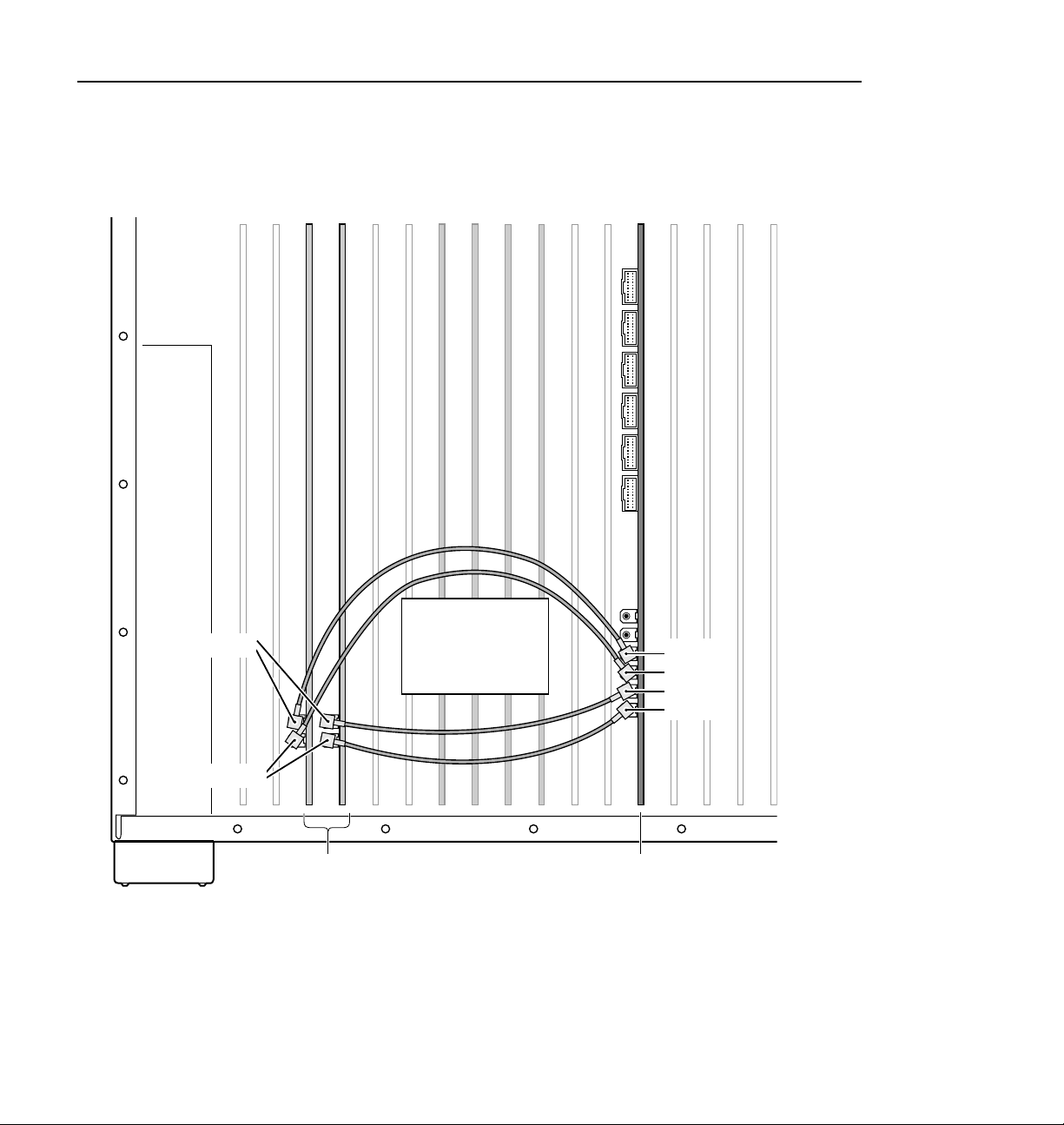
Two Serial Digital I/O Boards and One ASPB
The example in Tabl e 5 and Figure 9 shows audio clock and Sharcnet cabling for
a PDR204D having two Serial Digital I/O boards and one ASPB.
Table 5. Cabling for two Seri al Digital I/O boards and one ASPB
Cable Type Serial Digital
I/O Slot
Sharcnet J14 Sharcnet In Sharcnet Out 1
Sharcnet J14 Sharcnet Out Sharcnet In 1
Sharcnet J15 Sharcnet In Sharcnet Out 2
Sharcnet J15 Sharcnet Out Sharcnet In 2
Audio clock J14 Channel A Audio 1
Audio clock J14 Channel B Audio 2
Audio clock J15 Channel A Audio 3
Audio clock J15 Channel B Audio 4
Serial Digital I/O
Connection
ASPB1
Connection
(J5)
42 DVCPRO Upgrade Installation
Page 43

ASPB Audio Clock and Sharcnet Cabling Examples
J17 J13J16
Sharcnet In
Sharcnet Out
Channel B
J11 J9
J15 J14 J6J7
J12
PCI Interconnect Bd.
J10
DVCPRO CODEC
(Do not place cabling
on top of board.)
Fibre Channel
Master EDR
J8
Slave EDR
J4 J3 J2
J5
Sharcnet Out 1
Sharcnet Out 2
Sharcnet In 2
Sharcnet In 1
Audio 4
Audio 3
Audio 2
Audio 1
J1
Channel A
Serial
Digital I/O
Figure 9. ASPB cabling with two Serial Digital I/O boards and one ASPB
ASPB
0516-1
DVCPRO Upgrade Installation 43
Page 44

DVCPRO Board Installation
Three Serial Digital I/O Boards and Two ASPBs
The example in Ta ble 6 and Figure 10 shows audio clock and Sharcnet c abling f or
a PDR204D having three Serial Digital I/O boards and two ASPBs.
Tabl e 6. Cabling for three Serial Digital I/O boards and two ASPBs
Cable Type Serial Digital
I/O Slot
Sharcnet N/A N/A Sharcnet
Sharcnet N/A N/A Sharcnet
Sharcnet J13 Sharcnet In Sharcnet Out 1 N/A
Sharcnet J13 Sharcnet Out Sharcnet In 1 N/A
Sharcnet J14 Sharcnet In Sharcnet Out 2 N/A
Sharcnet J14 Sharcnet Out Sharcnet In 2 N/A
Sharcnet J15 Sharcnet In N/A Sharcnet Out 1
Sharcnet J15 Sharcnet Out N/A Sharcnet In 1
Audio clock J13 Channel A Audio 1 N /A
Audio clock J13 Channel B Audio 2 N/A
Audio clock J14 Channel A Audio 3 N/A
Audio clock J14 Channel B Audio 4 N/A
Audio clock J15 Channel A N/A Audio 1
Serial Digital I/O
Connection
ASPB 1
Connection
(J5)
Expansion 2
Expansion 1
ASPB 2
Connection
(J7)
Sharcnet
Expansion 1
Sharcnet
Expansion 2
Audio clock J15 Channel B N/A Audio 2
44 DVCPRO Upgrade Installation
Page 45

ASPB Audio Clock and Sharcnet Cabling Examples
J17 J13J16
Sharcnet In
Sharcnet Out
Channel B
J11 J9
J15 J14 J6J7
J12
Two-codec
DVCPRO (PDFDV02)
PCI Interconnect Bd.
J10
Four-codec
DVCPRO (PDFDV04)
(Do not place cabling
on top of board.)
Fibre Channel
Master EDR
J8
Slave EDR
J4 J3 J2
J5
Sharcnet Out 1
Sharcnet Out 2
Sharcnet In 2
Sharcnet In 1
Sharcnet
Expansion 1
Sharcnet
Expansion 2
Audio 4
Audio 3
Audio 2
Audio 1
J1
Channel A
Serial
Digital I/O
Figure 10. ASPB cabling with three Serial Digi tal I/O boards and two ASPBs
ASPB2 ASPB1
0516-9
DVCPRO Upgrade Installation 45
Page 46

DVCPRO Board Installation
Two Analog Composite I/O Boards and One ASPB
The example in Ta ble 7 and Figure 11 shows audio clock c ablin g for a PDR204A
having two Analog Composite I/O boards and one ASPB.
Table 7. Cabling for two Analog Composite I/O boards and one ASPB
Cable Type Analog
Composite I/O
Board
Slot
Audio clock J14 Channel A Audio 1
Audio clock J14 Channel B Audio 2
Audio clock J15 Channel A Audio 3
Audio clock J15 Channel B Audio 4
Analog
Composi t e I/O
Board
Connection
ASPB1
Connection
(J5)
46 DVCPRO Upgrade Installation
Page 47
ASPB Audio Clock and Sharcnet Cabling Examples
J17 J13J16
Channel B
J11 J9
J15 J14 J6J7
J12
PCI Interconnect Bd.
J10
DVCPRO CODEC
(Do not place cabling
on top of board.)
Fibre Channel
Master EDR
J8
Slave EDR
J4 J3 J2
J5
Audio 4
Audio 3
Audio 2
Audio 1
J1
Channel A
Analog
Composite I/O
Figure 11. ASPB cabling with two Analog Composite I/O boards and one ASPB
ASPB
0516-2
DVCPRO Upgrade Installation 47
Page 48
DVCPRO Board Installation
Three Analog I/O Boards and Two ASPBs
The example in Ta ble 8 and Figure 12 shows audio clock c ablin g for a PDR204A
having three Analog Composite I/O boards and two ASPBs.
Tabl e 8. Cabling for three Serial Digital I/O boards and two ASPBs
Cable Type Analog
Composite
I/O Board
Slot
Sharcnet N/A N/A Sharcnet
Sharcnet N/A N/A Sharcnet
Analog
Compos ite I/O
Board
Connection
ASPB 1
Connection
(J5)
Expansion 2
Expansion 1
ASPB 2
Connection
(J7)
Sharcnet
Expansion 1
Sharcnet
Expansion 2
Audio clock J13 Channel A Audio 1 N /A
Audio clock J13 Channel B Audio 2 N/A
Audio clock J14 Channel A Audio 3 N/A
Audio clock J14 Channel B Audio 4 N/A
Audio clock J15 Channel A N/A Audio 1
Audio clock J15 Channel B N/A Audio 2
48 DVCPRO Upgrade Installation
Page 49

ASPB Audio Clock and Sharcnet Cabling Examples
J17 J13J16
Channel B
J11 J9
J15 J14 J6J7
J12
Two-codec DVCPRO (PDFDV02)
PCI Interconnect Bd.
J10
Master EDR
Four-codec DVCPRO (PDFDV04)
(Do not place cabling
on top of board.)
J8
Slave EDR
Fibre Channel
J4 J3 J2
J5
Sharcnet
Expansion 1
Sharcnet
Expansion 2
Audio 4
Audio 3
Audio 2
Audio 1
J1
Channel A
Analog
Composite I/O
Figure 12. ASPB cabling with three Analog Composite I/O boards and two ASPBs
ASPB2 ASPB1
0516-8
DVCPRO Upgrade Installation 49
Page 50

DVCPRO Board Installation
Detailed Explanation Of ASPB Cabling
If you are fo llowing one of the cabling examp les, this s ection is for reference on ly.
Read this information if you have questions about the ASPB cabling.
Audio Clock Cabling
When the Profile system records, audio sampling must be r eferenced to t he video
signal, otherwise audio artifacts will occur. The ASPB hardware and Prof ile
software allows the you to select the appropriate audio sample reference for
recording as follo w s:
• When recording synchronous video feeds, use “system clock” derived from
house reference and supplied to the ASPB through its motherboard
connector.
• When recording non-synchronous video feeds, use the reference signal
supplied by the video input card over an Audio Clock coaxial cable
connected t o the AS PB .
Each ASPB has four audio clock input connectors for attaching an audio clock
reference. These connectors are attached by coaxial cable to the video input
boards. The cables carry a 27MHz refere nce signal derived from the video input
to the ASPB. This signal is used as a reference for the audio phase lock loops.
(See Figure 13.)
Audio
Sample PLLs
Audio Clock1
Audio Clock2 Group2
Audio Clock3 Group3
Audio Clock4
Figure 13. Audio clock groups and reference selectio n
Reference
Select
Crosspoint
System Clock
(from Genlock bd. through
the Motherboard connector)
Group1
Group4
Audio
Sample Clocks
Group1 Clock
(Channels 1-4)
Group2 Clock
(Channels 5-8)
Group3 Clock
(Channels 9-12)
Group4 Clock
(Channels 13-16 )
0047-14
50 DVCPRO Upgrade Installation
Page 51

Detailed Explanation Of ASPB Cabling
A single ASPB supports 16 audio channels. These 16 channels are divided into
four audio groups with four audio channe ls in each group. Group 1 consists of
channels 1 to 4. Group 2 consists of channels 5 to 8, and so on up to Group 4.
There is a phase lock l oop and a udio sample cloc k for eac h audio group 1 thr ough
4 as seen in Figure 13. You can also see in Figure 13 how the Reference Select
Crosspoi nt allow s sele ct ion o f the ref eren c e to the A ud io Sa mp l e Phas e L ock
Loops. Profile software allows the user to se lect the appropria te reference for the
Audio Sample Phase Lock Loops, either “system clock” derived from house
reference or one of the four audio clocks derived from video inputs.
When the potentia l for recording non-synchronous video feeds exists, it becomes
important to se lect the cor rect vi deo refe rence and to have the coa xial a udio cl ock
cables connected properly.
Here are the audio clock cabling guidel ines.
• Profile software recognizes and numbers video inputs beginning with
Channel A of the board in the lowest numbered motherboard slot.
• When two ASPBs are installed, ASPB1 is the ASPB in the lower number
board slot and ASPB2 is in the higher numbered slot.
• Profile software refers to the four ASPB audio clock references as
“Video Input 1” through “Video Input 4”.
• ASPB1 audio clocks 1 through 4 should be connected to video inputs 1
through 4.
• ASPB2 audio clocks 1 through 4 should be connected to video inputs 4
through 8, if installed.
• Audi o clock reference s connected to ASPB1 cannot be used by ASPB2. The
opposite is also true, references attached to ASPB2 cannot be used by
ASPB1.
NOTE: Do not connect any audio c lock cables to the connectors on the four
channel Composite Analog Video Output board. These are system clock
connectors and are not used because the ASPB receives system clock through
its motherboard connecto r.
DVCPRO Upgrade Installation 51
Page 52

DVCPRO Board Installation
If your Profile unit has one ASPB, you can connect only four audio clock
references t o it. If y our Profil e u nit has two ASPBs install ed, a to tal of e ight audio
clocks can be connected.
In practice, if your Pro file unit has more vid eo inputs than the number of ASPB
clock inputs, you should connect audio clocks from video inputs that might
record video that is not genlocked to your house reference.
Any video inputs that are not supplying a record clock to the ASPB should be
locked to your house reference, if audio is to be associated with those inputs.
Otherwise, audio clock errors could occur during recording.
For more information on audio input clocking refer the Audio Configuration
information in the Profile Family User Manual.
Sharcnet Cabling
Serial digital I/ O boards (SDI boards) with Sharcnet connectors have embedded
audio capabilit y. These SDI boa rds extrac t audio fro m incoming vide o, rout e it to
the ASPB, and receive audio output from the ASPB to be embedded in the serial
digital stream. Sharcnet cables are used to route the audio between the ASPB and
SDI boards.
On both the ASPB and SDI board there are Sharcnet In and a Sharcnet Out
connectors. These are shown in Figure 9 on page 43. In general, ASPB Sharcnet
Outs are conn ected to SDI Sharcn et Ins, and ASPB Sharcnet Ins are c onnected to
SDI Sharcnet Outs. Simple enough, but connection order is important.
Here are the guidelines for making the Sharcnet connections:
• Beginning with the ASPB in the lowest numbered slot (ASPB1), Sharcnet
In1/Out1 are connected to Sharcnet Out /In of the serial digital video board
in the lowest numbered slot.
• Next, Sharcnet In2/Out2 are connected to Sharcnet Out/ In of the serial
digital video board in the next higher numbered slot.
• The pattern above continues for ASPB2 if two ASPBs are installed.
• The Exact number of Sharcnet cables will vary depending on how many
serial digital video I/O boards are installed.
• When two ASPBs are installed, Sharcnet Expansion 1 conn ectors on each
board are connected the Sharcnet Expansion 2 connectors on the other.
52 DVCPRO Upgrade Installation
Page 53

Board Location Guide
This board l ocation gui de is pro vided to help y ou in stall the DVCPRO boards in a
PDR200 Video File Server that is not an Option DV, that is, not shippe d from the
factory as DVCPRO ready. The board layout for an Option DV PDR200 eases
DVCPRO board installation, but other systems may require that you move
existing boards to accommodate the DVCPRO boards. This guide will help you
do that.
If you move any circuit boar ds, remember that some boards must oc cupy specific
slots, while others can be installed in almost any slot as long as their I/O
requirements are met (see Table 10 on page 57). The board location guide
identifies the vid eo router inputs and outputs of each Profile board currently
available, as well as the input and output connections on the video router
connectors on the motherboard.
This guide provides a general approach to board location. It explains the
relationship between the motherboard and video router connectors and provides
tables, charts and examples to as sist you in installing boards.
Video Router to Motherboard Relationship
Board Location Guide
The video router provides and contr ols video data to twelve connectors on the
motherboard. These video dat a connectors are align ed with the main motherboard
connectors for s lots J5 through J16. Since the Referenc e Genlock (Ref Gen) boar d
must occupy J16 to pro vide the nece ssary syste m clocks, thi s discussi on excl udes
J16.
When choosing a slot for a board, the major constraint f or a slot is how the board
connects to the video router . Not all boards require the same number of video I/O
connections, and not all video dat a connectors provide the same number of video
I/O connections. Therefore, you must know how many input and output
connections the board need s, if any, and the slots available tha t meet those needs.
Table 10 on page 57 lists each of t he boards which may be installed in the Profile
system and the recommended slots, possi ble alternatives, and restrictions f or each
board. If more than one slot is recommended or possible for a board, those slots
are listed in the order of preference.
DVCPRO Upgrade Installation 53
Page 54

DVCPRO Board Installation
Video Router I/O Connections
Now let’s look at the video router connections available at slots J5–J15. Table 9
shows a board location workshee t that shows the video router input and output
connections. The worksheet is blank except for the 5 board slots reserved for the
boards that are connected by the PCI Interconnect board. In this chart:
• The
Slot column lists each slot on the motherboard connected to the video
router.
• The
Board column is where you write the boards currentl y insta lled and the
name of the board you want to install.
• The
Input column identifies input connections available to the installed
boards from the video router. The numbers in the blocks correspond to the
order input connections are assigned at the video router connector.
• The
Output column identifies output connections availa ble from the
installed boar ds to the video rou ter. The numbers in t he blocks corre spond to
the order output connections are assigned at the video router connect or.
• The shaded blocks in the diagram indicate video router connections shared
between slots. A shar ed connec tion is avail abl e to eithe r slot, but not both at
the same time. For instance:
- The shaded input blocks betwe en slots J5 and J6, slots J7 and J8, slots J10
and J11, and slots J12 and J13 indicate shared input connections.
- The sha ded output blocks be tween slots J8 and J9, slots J10 and J11, and
slots J12 and J13 indicate shar ed output connections.
54 DVCPRO Upgrade Installation
Page 55

Video Router I/O Connections
Table 9. Board location chart
Slot Board Input
J5
J6
J7 1 1
J8 Slav e Enhanced Disk Recor der
J9 Fibre Channel (if installed) 1
J10 Master Enhanced Disk Recorder 1
J11
J12 DVCPRO CODEC (PDFDV02) 1
J13 2 4 3
J14 1 1
J15 1 1
DVCPRO CODEC (PDFDV04)
b
a. Shaded areas indicate router points shared between board slots ;
or out p ut is used by the bo a r d
.
a
Output
1
23
62
5
4
31
2
1
2
3
42
5
6
2
1
22
2
4
3
2
1
2
3
4 3 4
12
23
23
3
indicates which input
1
2
3
1
3
3
3
3
3
3
3
3
3
3
2
3
3 4
4 3
1
1
3
2
3
3 4
4 3 3
2
3
1
3
1
3
2
3
1
2
2
b. I f JPEG #2 and DVCPR O25 #4 are used , they must both be co nnec ted to the same video
input via the internal vid eo crosspoint router, otherw ise, the wrong video input may be
recorded. T o avoid this restriction, use one of t he other three JPEG co decs available in
the system.
a
3
DVCPRO Upgrade Installation 55
Page 56

DVCPRO Board Installation
Selecting a Board Location
Here’s how to use the tables to select a location for a board. Make a copy of
Table 9 t o use as a temp lat e fo r recording inform at io n for board pla cem en t .
1. Write the board na me in Table 9 and, referring to Table 10, put a check mark
3
) in each input and output block used by each board currently installed in
(
your Profile system. Start with the 1 block for each board.
2. Look in Table 10 to see the input and output requirements and both the
recommended slot and alternative slots for the board you want to install.
3. Look in Table 10 for a slot with the required video router connections
available. Starting with t he 1 block, put an 8 in each block that corresponds
to an input and output requirement for the newly added board. If the
recommended slot is occupie d, or there are not enough input or output blocks
available, lo ok at the al te rnat i ve slo ts.
4. If all input and output requirements for the board match the available ones
for the slot, write the board na me in the
the board.
NOTE: If you ca n’t find an open slot with the I/O connections which meets
the I/O requirements of the board you want to instal l, y ou will have to move
existing boards. You can use Table 9 and Table 10 to experiment with various
board locations before deciding on one.
Board column for the slot and install
56 DVCPRO Upgrade Installation
Page 57

Selecting a Board Location
Table 10. Board I/O requirements and restrictions for a PDR200 with DVCPRO boards
Board Video Router
Connection
Requirements
Inputs Outputs
CPU n/a n/a J1 None Reserved for PC card only. PC/VGA/LAN
VGA n/a n/a J2 None ISA only. Parallel p ort in S/N B050000 and U p
LAN n/a n/a J3 None EISA connection only. May be empty in
SCSI n/a n/a J4 None EISA connection only
RefGen n/a n/a J16 None Reference genlock
RS-422 n/a n/a J17 None EISA only
Master EDR 2 2 J10 None Must be adjacent to Fibre Channel (i f install ed).
Slave EDR 2 2 J8 None Must be adjacent to Fi bre Chann el (if installed ).
Fibre Channel None None J9 None Must be adjacent to Mas ter EDR in slot J1 0. 5
DVCPRO
CODEC (4-codec)
DVCPRO
CODEC (2-codec)
Analog Comp osite InNone 1 J6, J15 J5-15 Any open slot if bo ard i n adjace nt slot do es not
Analog Comp osite
Decoder
Analog Comp osite
I/O
Four Channel
Analog Out
Analog Comp osite
Monitor Out
Serial Digi tal I/O 2 2 J14, J15 J6, J7, J13 Cables must be able to reach ASPBs
CAV In None 1 J6 J5-15 Any open slot if boar d in adj acent slot do es not
Mix Effects 6 2 J6 J7 Only J6 and J7 have 5 inputs; board must be
Audi o Sig n al
Processing Board
(ASPB)
4 4 J11 None Must be adjacen t t o Master EDR board in s lot
2 2 J12 None Must be in sl ot J12. 5 slot PCI I nterconnect
None None J5, J14 J4-15 Must be adjacent to Analog Composite In.
2 2 J13, J14, J15 J5-J15 Any open slot if board in adj acent slot do es not
4 None J6, J7 J6, J7 Only J6 and J7 have 4 inputs and are available
4 None J6, J7 J6, J7 Only J6 and J7 have 4 inputs and are available
None None J5 (1st)
Recommended
Slots
J7 (2nd)
Other
Possible
Slots
combination board in S/N B050000 and Up.
S/N B050000 and Up.
5 slot PCI Interconnect required.
5 slot PCI Interconnect required.
slot PCI Interconnect required.
J10. 5 slot PCI Interconnect required.
required.
use the same shared router points. Must be
adjacent to the Analog Composite Decoder.
May be installed in J4 since i t does not requi r e
any router connections.
use the same shared router points.
in a DV CPRO PDR200.
in a DV CPRO PDR200.
use the same shared router points.
able to get a shared input (the 6th) from an
adjacent s lot (J5 or J8)
J5-J15 Any open slot since it require s no video router
connection s. Cabl es must be able t o reach v ideo
boards or additional AS PB. Second ASPB
necessary for 32 channels of audio.
Comments
DVCPRO Upgrade Installation 57
Page 58

DVCPRO Board Installation
Troubleshooting
If you experience a problem while performing the upgrade procedure or with
Profile system operation after all the inst al lat ion ste ps are com ple te d, fi rst check
all external connections to make sure they are properly made, then refer to the
troubleshooti ng aid which follows.
Troubleshooting Aid
This troubleshooting aid provides corrective action for some common problems
encountered when perfor ming this upgrade procedure. Search Table 11 for the
problem you are experiencing, then try the recommended action. Table 11 is
continued on several pages. If all else fails, contact Grass Valley Group Support.
Grass Valley Group Support contac t information is located on page 5 of this
manual.
Table 11. PDR200 DVCPRO upgrade procedure trou bleshooting table
Probl em Possible Cau se Action
BIOS Boot Error Message:
“EISA configuration error.”
Windows NT Error Message:
“At least one service or driver
failed during startup.”
Windows NT Warning message:
“Real Time Processor Not
Available - PDR Access Control
Service not responding”
and
“Real-Time Processor Failure -
No Media File Systems”
1. EISA configuration in Sy stem
CPU board CMOS is
corrupted or an EISA board
was added, removed or
moved.
1. A driver or service was not
installed properly or there
may be a hardware problem.
1. Media file system appears
corrupted because the SCSI
disk cables are not connected
or not connected properly.
1. Make sure the LAN, VGA, and Buslogic
SCSI adapter boards are in the slots
specified in Table 10 on page 57. Run the
Load CMOS utility as follows: Choose
Start | Programs | Profile Debug Tools
| Load CMOS. Press Enter to continue.
Shut down and restart Windows NT.
1. Open the Windows NT Event Viewer
application for more information. Refer to
your Windows NT documentation or
Windows NT Help for more information on
using the Event Viewer.
1. This error message will occur if there is a
hardware problem in the SCSI disk
system. If using external storage chassis,
check SCSI terminators and try checking
or reversing the external SCSI cables.
Remove the unit covers and verify all
SCSI cabling is connected properly (refer
to Figure 5 on page 28). Verify that SCSI
cable A is connected to the Master disk
recorder board and the SCSI cable C is
connected to the Slave disk recorder
board.
2. SCSI disk system failure.
2. Contact Grass Valley Group Support.
58 DVCPRO Upgrade Installation
Page 59

Troubleshooting Aid
Table 11. PDR200 DVCPRO upgrade procedure troubleshooting table (Continued)
Probl em Possib le C ause Actio n
VdrPanel will not start. 1. Corrupt PdrMovie data base
Distorted audio. 1. Audio clock cables connected
Embedded audio signal is
missing or does not match the
video.
after creating a new file
system.
incorrectly.
2. Wrong audio clock reference
source selection.
1. Incorrect input or output audio
mapping.
1. Open Windows NT Explorer. Delete
c:\pdrmovie_db directory, then shut down
and restart Windows NT. Try starting
VdrPanel again. The database will be
regenerated when VdrPanel is started
again.
1. Check audio clock cabling using your
diagrams or by referring to “Connecting
Audio Clock and Sharcnet Cables” on
page 41.
2. Refer to “Using the Profile
Configuration Manager” in the Profile
Family User Manual.
1. Refer to the PDR200 Audio section of
“Using the Profile Configuration Manager”
in the Profile Family User Manual.
2. Sharcnet cables connected
incorrectly.
Distorted video input. 1. Video router Output point
No video output from one or two
channels of a video board.
Video channel displays the
wrong video in E to E and
playback.
Video channel displays the
wrong video in playback, but
looks fine in E to E.
conflict.
2. Hardware fault
1. Incorrect video router
configuration.
2. Not enough router Input point
connections in the slot for this
board.
3. Hardware fault.
1. Incorrect video router
configuration.
2. Video router Input point
conflict.
1. Video router Input point
conflict.
2. Check sharcnet cabling using your
diagrams or by referring to “Connecting
Audio Clock and Sharcnet Cables” on
page 41.
1. Verify the board is not using a video router
Output point shared with another board in
an adjacent slot. Refer to “Video Router
I/O Connections” on page 54.
2. Contact Grass Valley Group support.
1. Verify video router crosspoints. Refer to
the appropriate sections of the Profile
Family User Manual for the application
you are using.
2. Verify the board slot has enough video
router Input points to support the video
board. Refer to“Video Router I/O
Connections” on page 54.
3. Contact Grass Valley Group support.
1. Verify video router crosspoints. Refer to
the appropriate sections of the Profile
Family User Manual for the application
you are using.
2. Verify the board is not using a video router
Input point shared with another board in
an adjacent slot. Refer to “Video Router
I/O Connections” on page 54.
1. Refer to “Restrictions When Using JPEG
and DVCPRO” on page 17.
DVCPRO Upgrade Installation 59
Page 60

DVCPRO Board Installation
Table 11. PDR200 DVCPRO upgrade procedure troubleshooting table (Co nti nued)
Probl em Possible Cau se Action
Initializing Real-time Processor”
message stays on screen and
Profile applications won’t run.
DVCPRO Boards do not appear
in bottom of Configuration
Manager window.
1. i960 real-time processor failed
to initialize because no media
file system could be found.
2. i960 real-time processor failed
to initialize.
1. Wrong version of Profile
System Software installed.
2. Hardware fault.
1. See portions of this table regarding
Real-time Processor - No media file
systems found.
2. This message sometimes appears while
Profile system software is starting up. If
the message remains longer than one or
two minutes and no other messages are
displayed, contact Grass Valley Group
Support.
1. Install Profile System Software 3.1.
2. Contact Grass Valley Group Support.
60 DVCPRO Upgrade Installation
 Loading...