

Page 1
CameraMan
CONTROL CENTER
Installation and Operation Manual
L1201101 Rev B
1998
Page 2

Contacting Grass Valley
Region Voice Fax Address Web Site
North America (800) 547-8949
Support: 530-478-4148
Pacific Operations +852-2585-6688
Support: 852-2585-6579
U.K., Asia, Middle East +44 1753 218 777 +44 1753 218 757
France +33 1 45 29 73 00
Germany, Europe +49 6150 104 782 +49 6150 104 223
Copyright © Grass Valley. All rights reserved.
Grass Valley Web Site
The www.thomsongrassvalley.com web site offers the following:
Online User Documentation — Current versions of product catalogs, brochures,
data sheets, ordering guides, planning guides, manuals, and release notes
in .pdf format can be downloaded.
FAQ Database — Solutions to problems and troubleshooting efforts can be
found by searching our Frequently Asked Questions (FAQ) database.
Sales: (530) 478-3347
Support: (530) 478-3181
+852-2802-2996
Grass Valley
P.O. Box 599000
Nevada City, CA 95959-7900
USA
www.thomsongrassvalley.com
Software Downloads — Software updates, drivers, and patches can be down-
loaded.
2 CameraMan Installation and Operation Manual
Page 3

Installation and Operations Manual
Table Of Contents
I. Meet Your CONTROL Center
▼ Congratulations On Your Purchase . . . . . . . . . . . . . . . . . . . . . .1
▼ General Information . . . . . . . . . . . . . . . . . . . . . . . . . . . . . . . .2
▼ For Your Safety . . . . . . . . . . . . . . . . . . . . . . . . . . . . . . . . . . .3
▼ CONTROL Center Components . . . . . . . . . . . . . . . . . . . . . . .4-5
▼ Rear Panel and I/O Connections . . . . . . . . . . . . . . . . . . . . . . .6
II. Install Your CONTROL Center
▼ CONTROL Center Block Diagrams . . . . . . . . . . . . . . . . . . . . . .7
▼ Installing Your CONTROL Center . . . . . . . . . . . . . . . . . . . . . . .8
▼ Connecting Your Video . . . . . . . . . . . . . . . . . . . . . . . . . . . . . .9
▼ Connecting Your Audio . . . . . . . . . . . . . . . . . . . . . . . . . . . . .10
▼ Connecting Genlock . . . . . . . . . . . . . . . . . . . . . . . . . . . . . . .11
Front Panel Indicators And Adjustments . . . . . . . . . . . .12
▼ Connecting Your CameraMan Cameras . . . . . . . . . . . . . . . . .13
III. Use Your CONTROL Center
▼ Knobs, Buttons, Slide Controls And Displays . . . . . . . . . . . .14-15
▼ Powering Up . . . . . . . . . . . . . . . . . . . . . . . . . . . . . . . . . . . .16
▼ HOME Menu Display . . . . . . . . . . . . . . . . . . . . . . . . . . . . . . .17
▼ Video/Audio Selection Menu . . . . . . . . . . . . . . . . . . . . . . . . .18
▼ Video And Audio Switching . . . . . . . . . . . . . . . . . . . . . . .19-20
▼ Tally Light Control . . . . . . . . . . . . . . . . . . . . . . . . . . . . . . . . .21
▼ Additional HOME Menu Displays . . . . . . . . . . . . . . . . . . . . . .22
IV. Customize Your CONTROL Center
▼ CameraMan And CONTROL Center Setup . . . . . . . . . . . . . . . .23
▼ CameraMan Setup
• Setup Button Menu . . . . . . . . . . . . . . . . . . . . . . . . .24
• Setup Camera Menus . . . . . . . . . . . . . . . . . . . . .24-25
• Soft Stops Menu . . . . . . . . . . . . . . . . . . . . . . . . . . .26
• Pan/Tilt Default Menu . . . . . . . . . . . . . . . . . . . . . . .26
• Camera Default Menu . . . . . . . . . . . . . . . . . . . . . . .26
▼ CONTROL Center Setup
• Setup CONTROL Center Menu . . . . . . . . . . . . . . . . .27
• Setup Poll Cams Menu . . . . . . . . . . . . . . . . . . . . . .27
▼ Setting Camera Movement Parameters
• Location Presets . . . . . . . . . . . . . . . . . . . . . . . . . . .28
• Preset Speed and AutoTRACK . . . . . . . . . . . . . . .28-29
• Using AutoTRACK . . . . . . . . . . . . . . . . . . . . . . . . . .29
• AutoTRACK Views . . . . . . . . . . . . . . . . . . . . . . . . . .30
• Tracking Adjustments . . . . . . . . . . . . . . . . . . . . . . .31
• AutoTRACK LCD Menus . . . . . . . . . . . . . . . . . . .32-33
▼ Controlling the Camera’s Video Parameters (3-CCD only)
• Menu LCD Menus (video) . . . . . . . . . . . . . . . . . . . .34
• Camera Adjust LCD Menus and Submenus . . . . . .34-40
V. Appendices
▼ A: Troubleshooting . . . . . . . . . . . . . . . . . . . . . . . . . . . . . .41-43
▼ B: Glossary and Specications . . . . . . . . . . . . . . . . . . . . . . . .44
▼ C: Pin-out Diagrams . . . . . . . . . . . . . . . . . . . . . . . . . . . . . . .45
▼ D: Default Reset Settings . . . . . . . . . . . . . . . . . . . . . . . . . . . .46
▼ E: LCD Handling Precautions . . . . . . . . . . . . . . . . . . . . . . . . .47
▼ Notes . . . . . . . . . . . . . . . . . . . . . . . . . . . . . . . . . . . . . . . .48
Page 4
Meet Your CONTROL Center
Page 1
Congratulations On Your Purchase
This manual covers the connection, conguration, and operation of your new CameraMan
CONTROL Center. The CONTROL Center combines robotic camera control, audio/video
switching, proven autoTRACK capabilities (in autoTRACK models), location
presets, and virtual CCU control for up to eight cameras.
The CONTROL Center consists of a two-piece design: the CONTROL Center Control Unit
connected via RS-232 to the CONTROL Center Switcher.
The CameraMan CONTROL Center can direct the storing and recalling of up to 99 presets (1-CCD
camera) or 125 presets (3-CCD & 2112 cameras) and up to 15 autoTRACK views per camera. For
precise, smooth camera control, the CONTROL Center oers variable-speed camera pan/tilt (1CCD & 3-CCD) and variable-speed lens zooming (3-CCD & 2112) control through a joystick and
two slider bar adjustments. The powerful backlit LCD display and function buttons allow you to
adjust tracking views quickly, switch between audio/video devices, obtain pan/tilt position
readouts, and adjust each camera’s CCU settings (3-CCD only) on-the-y without compromising
the video.
You will see the following icons in this manual:
This icon alerts you to important instructions in the operation and maintenance of
your CameraMan CONTROL Center.
This icon alerts you to tips or noteworthy suggestions in the operation, use, or
maintenance of your CameraMan CONTROL Center.
This icon refers you to the General Pan/Tilt Camera installations and operations
manual that came with your camera.
The CameraMan CONTROL Center is your key to the ultimate in camera control. The CameraMan CONTROL Center is designed for
use with CameraMan cameras. Use this manual in conjunction with the installation and operations manuals for your
Cameraman 1-CCD or 3-CCD cameras.
Important Note
The CameraMan CONTROL Center is available in two versions: Composite video or S-video.
It is also available with or without autoTRACK capability. The CONTROL Center is
compatible only with:
• CameraMan Systems with software revision 6.0 or higher.
• PRM (Programmable Response Module) software revision 2.4 or higher.
To verify the software revision number, remove its ROM card per the instructions in the
camera system’s installation and operation manuals. The revision number is located on the
label on each chip. For software upgrades or questions, please contact
Product Support at (904) 596-3500.
Your CameraMan CONTROL Center should include
these components:
• One CONTROL Center Control Unit
• One Control Unit Power Supply
• One CONTROL Center Switcher
• One Switcher Power Cord
• Two 25 ft (7.6 m) CameraMan Communication Cable (RS-485)
• One 25 ft (7.6 m) Serial Cable (RS-232; female
to female)
• One 75-Ohm Terminator (Ext Ref)
• Four Self-sticking Rubber Pads
• One CONTROL Center Installation and Operations Manual
Page 5
Page 2
Installation and Operations Manual
General Information
Important Identification Numbers
Before starting to assemble and to use your CameraMan CONTROL Center, please take a
moment to find the Model and Serial number tag on your unit, and fill out the following
information.
Warning:
This is a Class A product. In a domestic environment this product may cause radio interference,
in which case the user may be required to take adequate measures.
PARKERVISION
™
MODEL # ________________
SERIAL # ________________
FCC ID # ________________
The terms Visibly Better, System II, IMAGE, WhisperDRIVE Plus, autoTRACK, MY TURN, and
General Pan/Tilt Camera System are registered trademarks of Grass Valley in the United
States of America.
The manufacturer reserves the right to change and warranty at any time without
notice or obligation.
No part of this manual may be copied or reproduced without express written consent of
Grass Valley.
Page 6
Meet Your CONTROL Center
Page 3
For Your Safety
Safety Notices
Instructions to the user:
1. Do not use this apparatus near water.
2. Clean only with a damp cloth.
3. Do not defeat the safety purpose of the polarized or grounding-type plug. A polarized plug
has two blades with one wider than the other. A grounding type plug has two blades and
a third grounding prong. The wide blade or the third prong is provided for your safety.
When the provided plug does not fit into your outlet, consult an electrician for
replacement of the obsolete outlet.
4. Unplug this apparatus during lightning storms or when unused for long periods of time.
5. Refer all servicing to qualified service personnel. Servicing is required when the apparatus
has been damaged in any way, such as a power supply cord or plug being damaged, liquid
being spilled or objects falling into the apparatus, the apparatus being exposed to rain or
moisture, not operating normally, or being dropped.
Safety Warning Graphics
The pictorial warnings placed on this equipment are for the user’s protection. Please
heed them.
Caution: Risk of Fire
For continued protection against risk of fire, replace only with same type T4A, 250 V~ fuse.
Pictorial warnings of this type give the type and rating of the specified replacement fuse.
Caution: Risk of Electrical shock
Where high voltage may be present, the pictorial warning on the right is used. This indicates
risk of electric shock. For your safety, DO NOT OPEN.
The following section describes important material and instructions regarding the installation and use. t.
Please:
• Read these instructions.
• Keep these instructions.
• Heed all warnings.
• Follow all instructions.
Page 7
Page 4
Installation and Operations Manual
CameraMan CONTROL Center Components
The following information introduces you to each of the CONTROL Center components and their features.
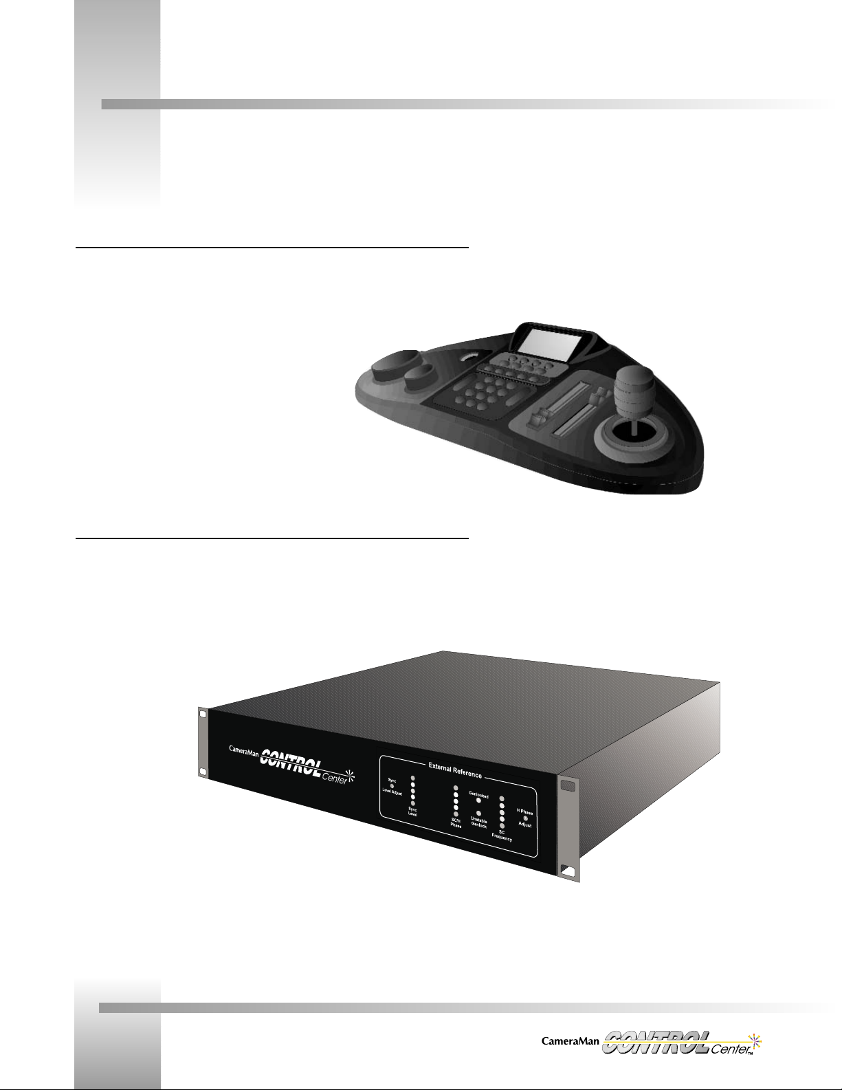
CONTROL Center Control Unit: Standard Unit and autoTRACK Unit
The Control Unit is a unique multiple-camera control device combining pan/tilt, zoom, focus, Iris,
CCU (3-CCD), autoTRACK (on autoTRACK-equipped models), and audio/video switch control.
Models with autoTRACK have autoTRACK view buttons located just above the numerical
keypad. Standard Units have a nameplate in this position.
CONTROL Center Switcher
The Switcher provides switching capability from a maximum of eight audio/video sources to a
maximum of four audio/video outputs. It provides eight genlock outputs for synchronizing the
eight video sources. The genlock signal can be generated internally, or referenced to an
external signal. The front panel has LED displays and adjustment pots for sync level and
horizontal phase when an external reference source is connected to the Switcher. They are not
used when the internal reference signal is being used.
Page 8
Meet Your CONTROL Center
Page 5
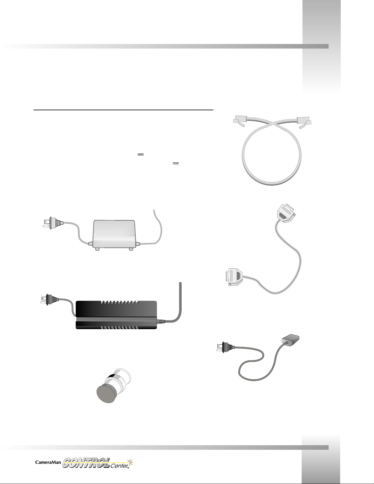
CameraMan CONTROL Center Components
Power and Connection Accessories
• 25 ft (7.6 m) CameraMan Communication Cable (RS-485).
• 25 ft (7.6 m) Serial (RS-232 Female-Female) Cable.
• CONTROL Center Switcher power cord.
• US Power Supply: 120 VAC~, 60 Hz, 100 W, 18VDC
Power Supply with attached cords,
or International Power Supply: 100-240 VAC~, 50/60 Hz, 2.0A, 20VDC
Power Supply.
• 75-Ohm terminator (Switcher Unit is shipped with this terminator connected to an External
Reference BNC on the back panel)
International Power Supply
(Control Unit)
75 Ohm Terminator
US Power Supply
(Control Unit)
Communication Cable
RS-232 Cable
Switcher Power Cord
Page 9
Page 6
Installation and Operations Manual
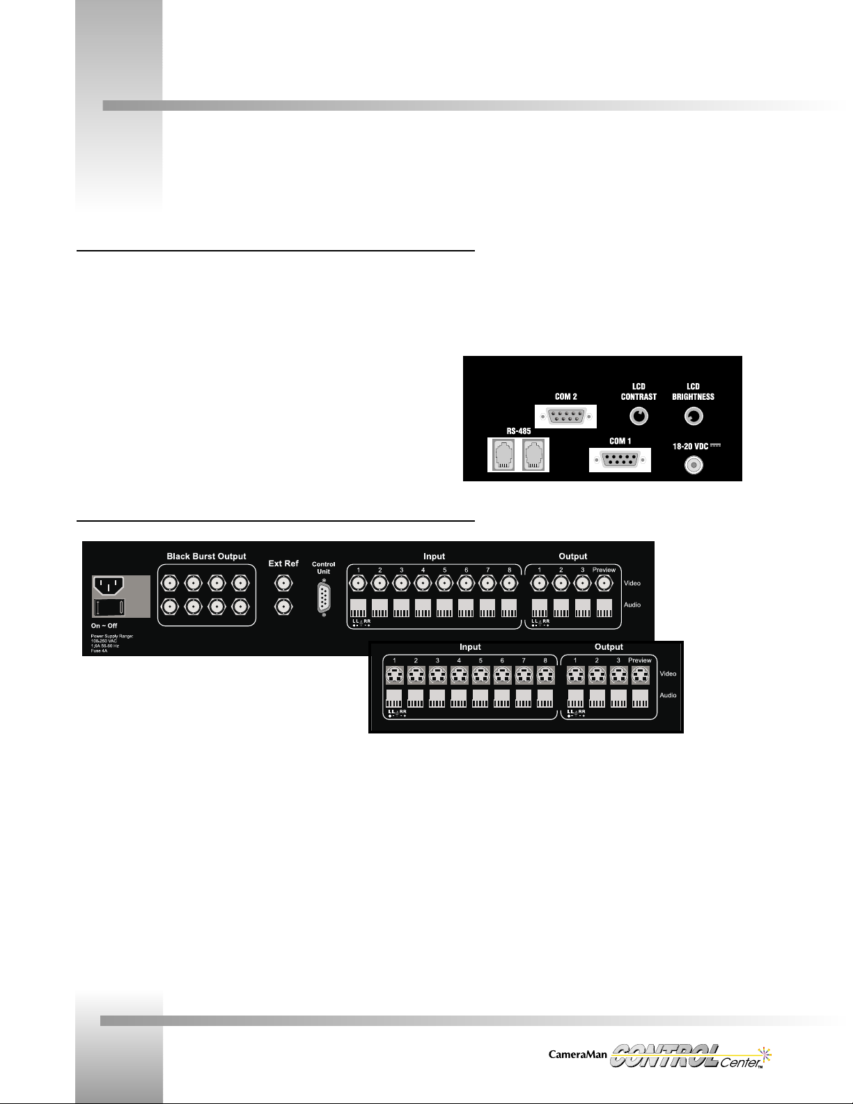
Rear Panel Controls and I/O Connections
Rear panel: CONTROL Center Control Unit
▼ LCD Contrast Knob – Used to increase or decrease the contrast on the CONTROL
Center’s LCD Display.
▼ LCD Backlight Brightness Knob – Used to increase or decrease the
amount of light showing through the LCD Display.
▼ RS-485 Ports – Used to connect Control Unit to CameraMan cameras.
▼ COM 1 – RS-232 Jack (female) used to connect to a PC to update CONTROL Center
software.
▼ COM 2 – RS-232 Jack (male) used to connect the Control Unit to the Switcher.
▼ DC Power Jack – Used to supply power to the Control Unit.
Rear Panel: CONTROL Center Switcher
▼ AC Power Cord Input – Used to supply power to the Switcher.
▼ On/Off Power Switch – Used to turn switcher on and off.
▼ Black Burst Outputs – Eight BNC connectors used to connect to the
genlock inputs of up to eight video devices.
▼ External Reference Inputs – BNC connectors used to connect to an
external genlock source (when not used as a loop thru, open
connector must be terminated with a 75 Ohm terminator.)
▼ Control Unit Port – Used to connect Switcher to CONTROL Unit.
▼ Switch Inputs – Video— Eight self-terminating BNC (top illustration) or S-video mini-
DIN style (bottom illustration) connectors used to connect to various video input
sources.
Audio – Eight five-position “Phoenix”-style connectors used to connect to various
balanced/unbalanced audio input sources. Inputs can be switched independently or
configured to follow their respective video inputs. (see page 10)
▼ Switch Outputs – Video— Three PROGRAM and one PREVIEW BNC (top) or S-video
mini-DIN style (bottom) connections. The three program outputs can be independently
selected or grouped together.
Audio – Three Program and one PREVIEW “Phoenix”-style connectors used to connect
to various balanced/unbalanced audio output devices.
SV Model
S-video switcher
with mini-DIN
inputs and
outputs
CV Model
Composite video
switcher with BNC
inputs and outputs
Page 10
Install Your CONTROL Center
Page 7
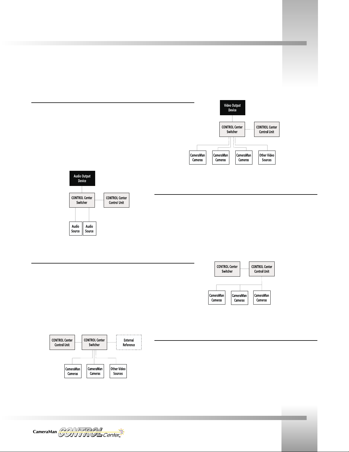
CONTROL Center Block Diagrams
Video I/O Connections
Input/output video connections from the Switcher rear panel to one or more devices are made
either by 75 Ohm coaxial cable terminated by BNC connectors(CV Model) or with S-video cable
terminated by mini-DIN connectors(SV Model).
Audio I/O Connections
Audio connections to one or more audio sources use cables with “Phoenix”- type connectors at
the Switcher.
Camera Control Connections
Camera Control connections from the Control Unit to CameraMan cameras use
RS-485 communication cables terminated by modular handset plugs. RS-485 “T”- style
connectors, or on some cameras, dual RS-485 ports, are used to daisy-chain up to 8 cameras
into a network.
Synchronizing Connections
Genlock connections from the Switcher to input sources are made with 75 Ohm coaxial cable
terminated by BNC connectors.
The following block diagrams explain how the CameraMan CONTROL Center connects to your cameras, video, audio, and external
synchronizing sources.
Page 11
Page 8
Installation and Operations Manual
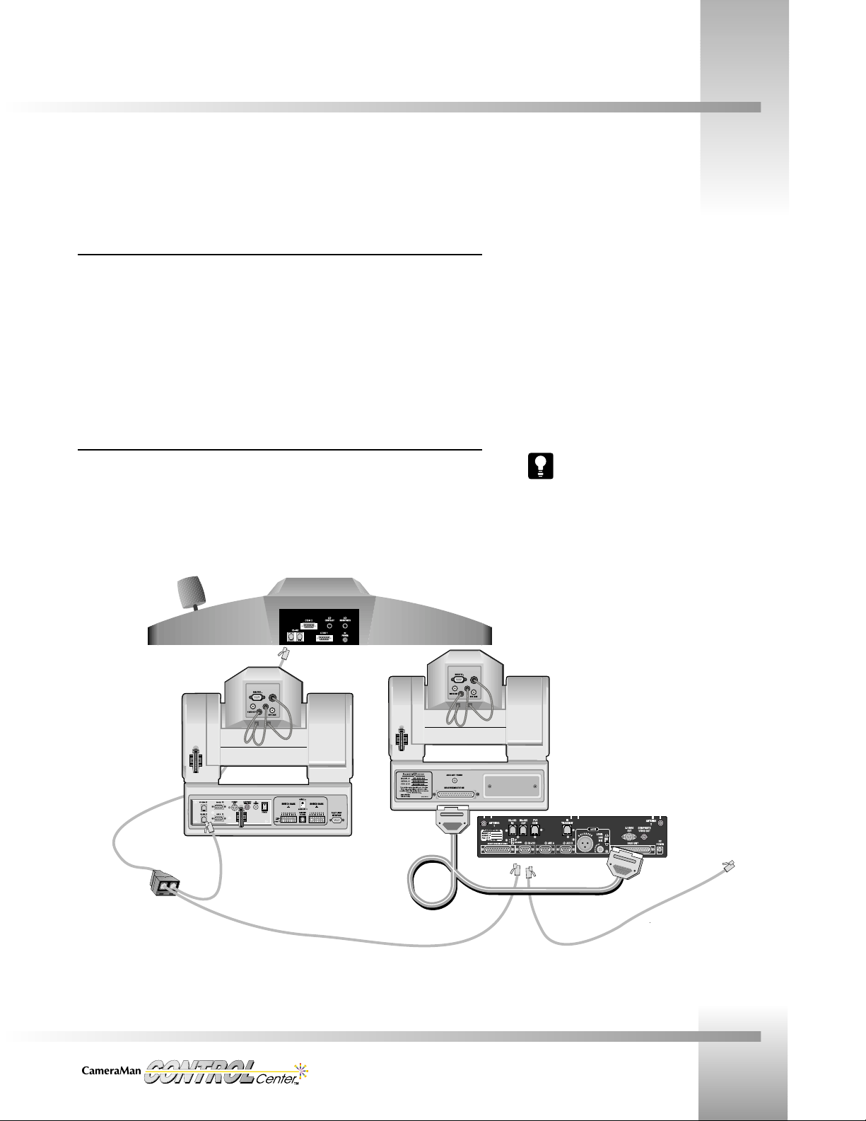
Installing Your CONTROL Center
Now that you are acquainted with your CONTROL Center’s hardware components and features, you can install it using these
procedures:
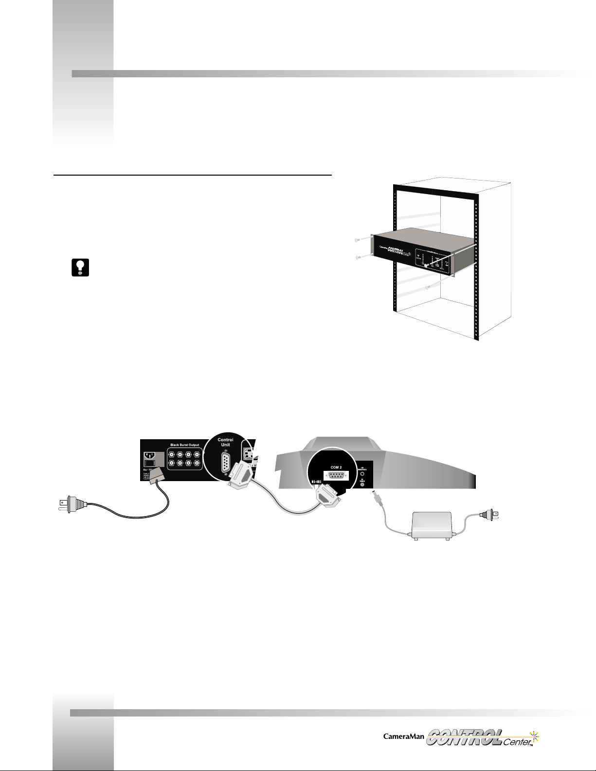
Control Unit and Switcher
1. Ensure that you have access to AC power near the Control Unit and the Switcher.
2. Choose where you want the Switcher to be located. Either:
• Rack mount the Switcher using four screws (as shown).
• Place the Switcher on a at surface.
For skid-protection, attach the self-sticking rubber feet.
3. Place the Control Unit where desired.
4. Connect the DC power plug of the Control Unit’s power supply to the Control Unit’s DC power
port.
5. Connect the female end of the AC power cord to the Switcher’s AC power port.
6. Connect one end of the Serial cable (RS-232) to COM-2 port on the Control
Unit and the other end to the Control Unit port on the Switcher.
AC Power from
wall to switcher
RS-232 connection
between control
unit and switcher.
DC Power from
control unit to wall
Switcher rack mounted
using four screws (not
provided).
Page 12
Install Your CONTROL Center
Page 9
Connecting Your Video
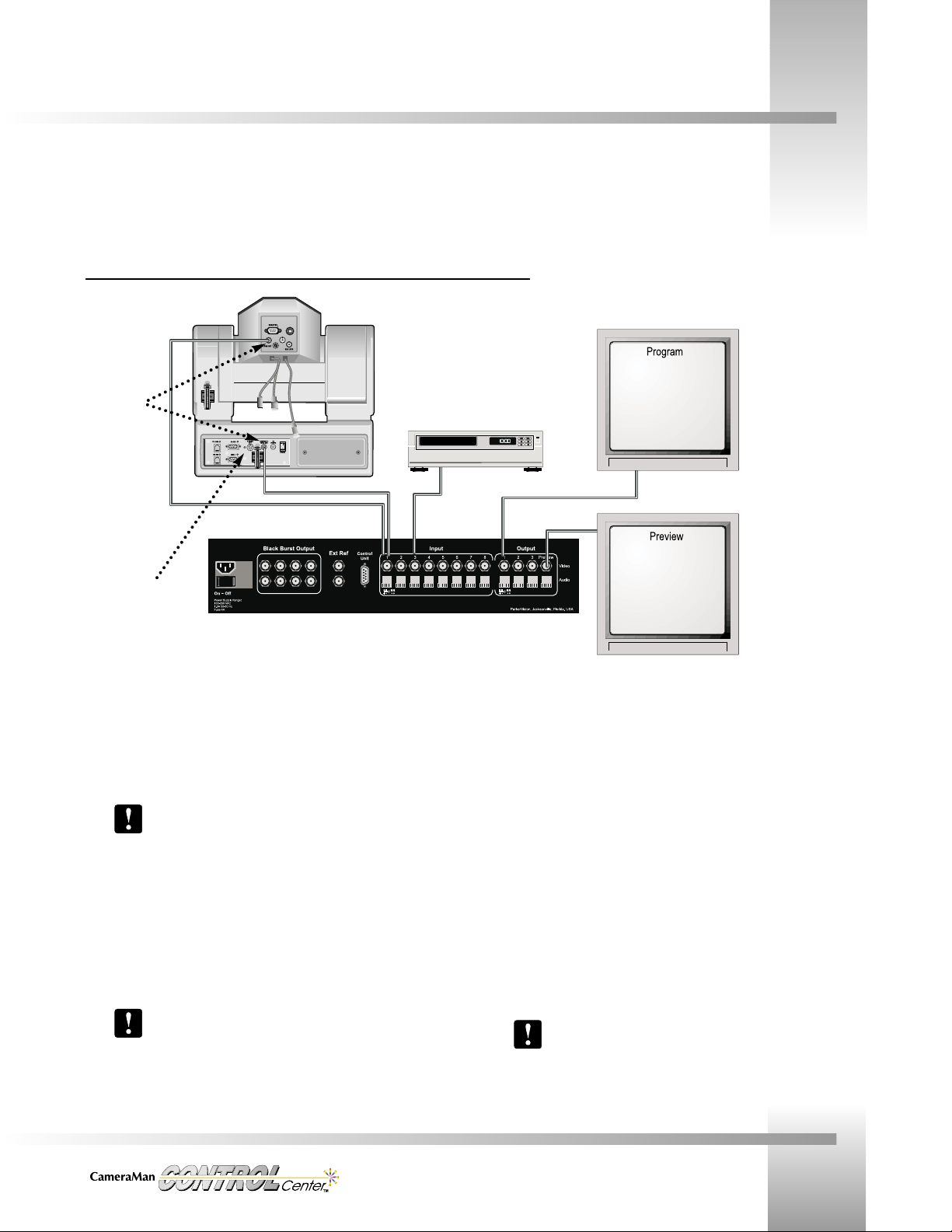
Switcher Video Connections
CameraMan Video Output to Switcher Inputs
1. Using cables with the appropriate BNC (composite) or mini-DIN (S-Video)
connectors, connect the video output from Camera one to the Switcher
video input one.
3-CCD CameraMan cameras have two BNC (composite) video out
jacks: one located at the top on the back of the camera block, and
the other on the mini docking station on the base unit. Either can
be used to connect to the switcher. For S-Video, use the jack on
the mini docking station.
2. Continue connecting CameraMan cameras in this fashion (Camera two video
output to Switcher video input two, Camera three video ouput to Switcher
video input three, etc.) until all CameraMan cameras have been connected.
All CameraMan cameras must be addressed so that their camera
number matches their video input number to the switcher (see
page 23).
Connecting Other Video Sources to Switcher Inputs
1. Once all CameraMan cameras have been connected, the unused video inputs
can be used for other video input devices (i.e. VTR’s, document cameras,
laser disc players, etc.)
2. Connect these devices using appropriate video cables.
Connecting Switcher Video Outputs
1. Using cables with the appropriate BNC (composite) or mini-DIN (S-Video)
connectors, connect Switcher video outputs 1-3 to the desired output devices
(i.e. broadcast video feed, program monitors, VTR’s, etc.)
2. Using a cable with the appropriate BNC (composite) or mini-DIN (S-Video)
connectors, connect the preview Switcher output to the preview monitor.
Refer to page 19 for details on how these outputs operate.
Connect other video source to
switcher’s video input jacks.
For S-Video systems,
use the S-Video jack
on the mini-docking
station
Connect monitors,
broadcast video
feeds, VTRs, etc.
to the switcher’s
video outputs.
Connect your
preview monitor
to the Preview
Output jack on
the switcher.
CameraMan
3-CCD cameras
have two
composite (BNC)
jacks. Use either
one to connect to
the switcher’s video
input. Connect up
to eight cameras.
Depending on the model you purchased, your CameraMan CONTROL Center supports either Composite or S-Video. The system
connects the same way for either video signal type. The following diagram shows a Composite (BNC) system:
Page 13
Page 10
Installation and Operations Manual
Connecting Your Audio
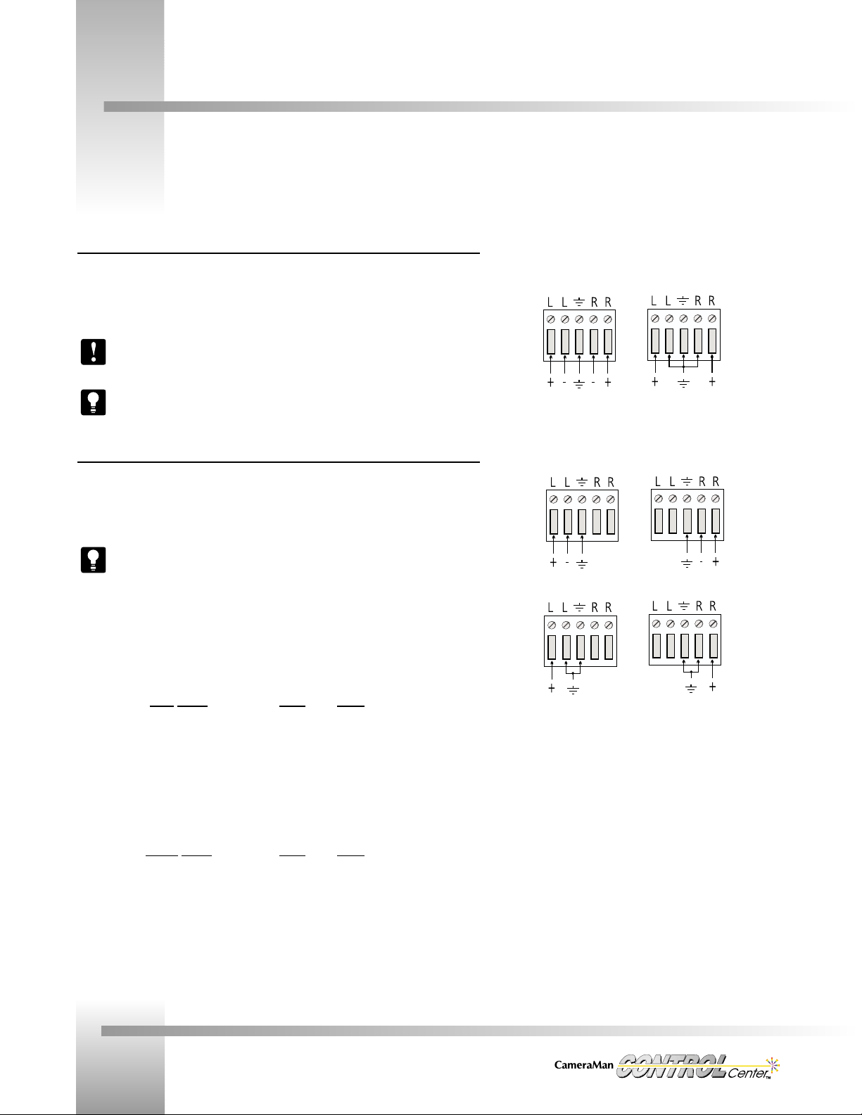
Switcher Audio Connections
The Switcher audio inputs will accept either balanced or unbalanced audio (mono or stereo).
Connect all inputs using the 5-position Phoenix connectors, according to the appropriate wiring
diagram.
If using audio from a CameraMan Presenter camera, the audio must be connected to
the same input number to which the video is connected.
It is usually easier to unplug the connector, make the wiring connections, and then
plug in the connector.
Switching Relationships
Any of the 8 audio inputs can be switched to any of the 4 audio outputs. However, when
switching video, there is, by default, a direct one-to-one relationship between audio and video
inputs (i.e. audio follows video). If desired, this relationship can be changed (refer to page 20).
For best results, connect each input source’s video and audio to the same input
number on the switcher. Do the same for each output source.
The chart below is an example of how to connect a typical system with one Presenter camera,
two General Pan/Tilt cameras, a VTR, and laser disc player used as video/audio inputs. In
addition, two program monitors, a VTR, and a preview monitor are used as video/audio
outputs.
Input
Source Video Audio
Presenter Camera . . . . . . . . . .Input 1 Input 1
General P/T Camera . . . . . . . . . .Input 2 NA
General P/T Camera . . . . . . . . . .Input 3 NA
VTR . . . . . . . . . . . . . . .Input 4 Input 4
Laser Disc . . . . . . . . . . . . .Input 5 Input 5
Output
Source Video Audio
Program Monitor 1 . . . . . . . . . .Output 1 Output 1
Program Monitor 2 . . . . . . . . . .Output 2 Output 2
VTR . . . . . . . . . . . . . . .Output 3 Output 3
Preview Monitor . . . . . . . . . . .Preview Preview
STEREO Audio Wiring
Balanced Unbalanced
MONO Audio Wiring
Balanced
or
Unbalanced
or
Page 14
Install Your CONTROL Center
Page 11
Connecting Genlock
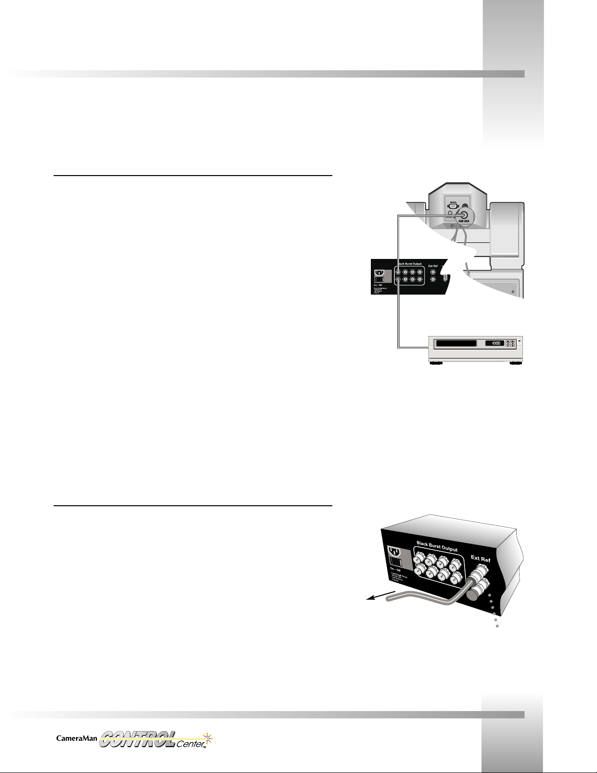
Genlock Connections — Internally Generated Reference Signals
The CONTROL Center contains an internal Black Burst generator in the Switcher Unit. Black
Burst signals are output to 8 BNC connectors on the back panel of the Switcher. Devices
connected to any of the Black Burst outputs can be synchronized (genlocked) to the internallygenerated reference signal.
Connecting Sync Signals To CameraMan Cameras:
1. Using high-quality video coaxial cable (75 ohm), terminated with BNC connectors, connect
the genlock input on each of the CameraMan cameras to one of the Black Burst outputs
on the back panel of the Switcher.
2. If necessary, use the Control Unit to adjust the Horizontal (H) Phase and Sub-Carrier (SC)
Phase of each camera to compensate for cable distance and other timing differences in the
cameras (refer to page 40 for details).
Connecting Sync Signals To Other Video Sources:
1. Using high-quality video coaxial cable (75 ohm), terminated with BNC connectors, connect
the genlock input on each of the video sources to one of the Black Burst outputs on the
back panel of the Switcher.
2. If necessary, refer to the Owner’s Manual for the device to which you are connecting to
make timing adjustments.
Genlock Connections — External Reference Signals
If an external reference signal is connected to the Switcher unit, the internal Black Burst
generator will automatically use this signal as its reference. The adjustments and indicators on
the front panel of the Switcher are used for making minor adjustments to the sync signal.
External Reference (Loop Thru) Input
When an external genlock source is connected to the Control Center Switcher it can be
connected to either of the External Reference (Loop Thru) BNC connectors on the rear panel. If
the loop thru capability is not going to be used (i.e. connecting another genlockable device to
the remaining BNC) a 75 Ohm terminator must be connected to the remaining BNC. The inputs
accept either Black Burst or video but the video content must not extend below -20 IRE.
Connect up to eight cameras or
other video sources to Black Burst
outputs.
To external Black
Burst generator
75 Ohm Terminator
Page 15
Page 12
Installation and Operations Manual
Connecting Genlock
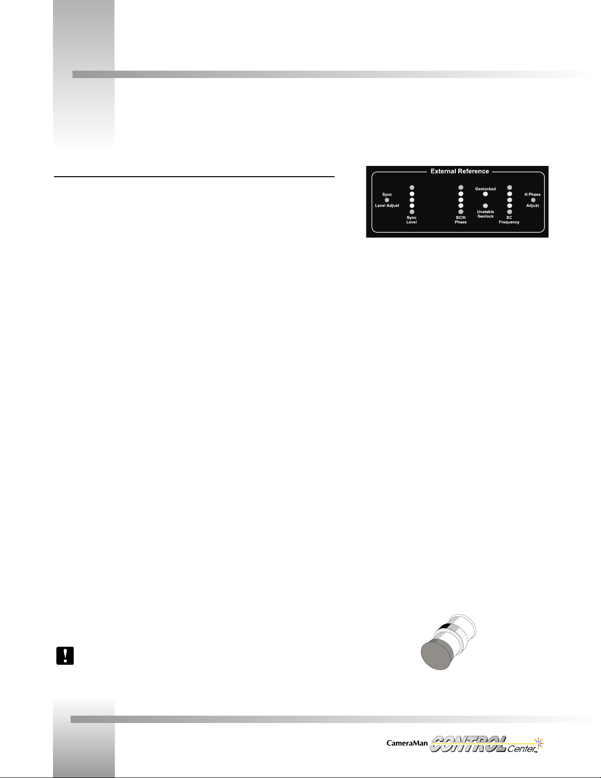
Front Panel Indicators and Adjustments
When using an external genlock source, the Switcher front panel LEDs help diagnose any
problems with genlocking. The LEDs provide information about the signal present at the
External Reference (loop thru) input. This feature is useful when trying to sync the CONTROL
Center and its associated devices to another sync source in a studio.
Sync-Level LEDs
• Green: proper level.
• Yellow: if either yellow is lit, then signal amplitude is out of tolerance.
• Red: amplitude too far from tolerance to achieve genlock. Unit will free run.
Sync-Level Adjust: Adjusts input signal until the green LED lights. Does not affect any output signal.
SC/H - Phase
• Green: all 3 green LEDs lit means input signal at Loop Thru meets RS-170A SC/H
specifications.
• Yellow and Green: 1 yellow and 2 greens lit means input signal has an SC/H error of
greater than 45 degrees.
• Center Green: if center green is not lit, then SC/H is beyond spec where Color Field One is
ambiguous and field lock is impossible.
Frequency
• Center Green: lit means input signal is correct frequency
• Yellow: if either yellow is lit, then frequency does not meet RS-170A specs although unit
may still genlock.
• Red: if either red is lit, then frequency is farther off spec and, if extremely off spec, then
the Unstable red LED will light.
Unstable: If lit, then the internal oscillator frequency would need an order of 2Hz change (out
of 3,579,545 Hz) within a single frame in order to maintain genlock with the incoming signal.
Genlocked: Lights green when unit achieves genlock.
Horizontal Phase Adjust: Adjusts the timing of the Black Burst output signal relative to the
external reference input signal.
If the external reference loop thru connector is not being used, be sure to terminate
the unused connector with a 75-ohm terminator (supplied).
75 Ohm Terminator
Page 16
Install Your CONTROL Center
Page 13
Connecting Your CameraMan Cameras
Camera Communications
The CONTROL Center communicates with CameraMan cameras through a CameraMan
Communication RS-485 cable connected to an RS-485 out port on the Control Unit. A single
camera is connected by plugging one end of the communication cable (each end has a modular
handset plug) into the RS-485 port on the Control Unit and plugging the other end into the
RS-485 port on the mini or main docking station of the camera. Multiple cameras are daisychained together using additional communication cables and T-connectors if a camera has only
one RS-485 port or if the camera has two RS-485 ports, using additional cables and both ports.
Connecting to AC
The Power supply for the Control Unit and the AC cord for the Switcher were connected to
their units in the first installation steps. At this point, connect the AC plugs of the Control
Unit’s power supply and the Switcher’s power cord to AC outlets.
Do not power up until you have read the Power Up sequence in this manual.
After physically connecting all devices
and before Power Up, refer to page
23, the CameraMan and CONTROL
Center Setup section of this manual,
for information concerning camera
addresses and dip switch positions.
RS-485 from CONTROL
Center to T-Connector
T-Connector
RS-485 from T-Connector to
non-autoTRACK CameraMan
37-pin connector from
Main Docking Station to
autoTRACK equipped
CameraMan
RS-485 from T-Connector to
RS-485 IN port on Main
Docking Station
RS-485 from RS-485
OUT port on Main Docking
Station to up to 6 additional cameras
daisy-chained together
Page 17

Page 14
Installation and Operations Manual
Knobs, Buttons, Slide Controls And Displays
Look at the top of your Camera Control Unit. It is divided into four sections: the knobs (left), the buttons (lower-middle), the slide
controls and joystick (right), and the LCD display (upper-middle).
Left Side: Knobs and Buttons
▼ Focus Control – Used to manually adjust the focal point of the lens.
▼ Power Switch – Press to turn the CONTROL Center on and off. Red LED lights when
power is ON.
▼ Auto Iris – Press to turn on. The active (selected on Home screen) CameraMan camera
will automatically adjust the IRIS and GAIN (IRIS only on 3-CCD cameras) to maintain a
constant video level. The auto iris light illuminates when active.
▼ Manual Iris – Used to manually adjust the camera’s IRIS to brighten and darken the video
picture. Range: 0(closed) to 31 (3-CCD), 0 (closed) to 16 (1-CCD)
Middle: Buttons
▼ Upper Section: Function Command Buttons – Used for LCD screen navigation.
As menus are called up and displayed, the functions for that menu appear above the
function command buttons. Activate the desired function by pressing the button.
Under the function buttons are the menu access buttons:
• HOME – Displays camera data and switching status.
• MENU – Displays menus allowing you to change Camera settings.
• SETUP – Displays menus enabling you to adjust Camera and CONTROL Center setup.
• BACK – Displays the last menu you were viewing.
▼ Middle Section: autoTRACK Views – Used to store/recall 10 custom views and five preset
autoTRACK Views: Left, Tight, Mid, Wide, and Right (autoTRACK model only).
▼ Lower Section: Numerical keypad – Used to store/recall location presets, select
video/audio input/outputs, select a camera for control in a multi-camera network, and to
Enter and Clear information found on the LCD display.
Upper
Section
Middle
Section
Lower
Section
Page 18

Use Your CONTROL Center
Page 15
The knobs, buttons, and slide controls are used in conjunction with the LCD display screen of your CameraMan CONTROL Center.
The screen provides menus for camera parameters, camera selection, and audio/video switching control. The LCD display shows
status of devices and provides selections for action.
CAMERA # and MENU TITLE FIELD
FUNCTION
COMMAND
FIELD 1
FUNCTION
COMMAND
FIELD 2
FUNCTION
COMMAND
FIELD 3
FUNCTION
COMMAND
FIELD 4
Control Unit LCD Display Features
The LCD screen, the four Function Command Buttons below it, and the four menu choice
buttons: Home, Menu, Setup, and Back, all work with each other to provide information and
to provide action options to the user.
▼ Camera # and Menu Title Field
Camera Control Mode: Numbers and words in this location identify the Camera Selected
and the title (Home, Setup, etc.) for each menu display.
Video/Audio Switching Control Mode: Numbers and words in this location identify the
Camera Selected and the title for each menu display.
▼ Function Command Fields
Camera Control Mode: Items in these locations correspond to the Function Command
Buttons directly below them. The command fields change depending on the menu displayed.
Video/Audio Switching Control Mode: Items in these locations correspond to the Function
Command Buttons directly below them. The information in the fields indicate the status of
the video or audio inputs and outputs. The screen toggles between video and audio when
you press the Enter key.
The initial menu on Power Up is always the Home menu. From the Home menu, you can
access additional menus by pressing the Menu, Setup, or indicated Function Command Button.
The screen information changes from menu to menu reflecting the menu’s purpose. The fields
over the Function Command Buttons also change from menu to menu offering additional
options per menu.
Knobs, Buttons, Slide Controls And Displays
Right Side: Slide Controls and Joystick
▼ Speed Control Slide Bars – Manual adjustment of the maximum speed of the
camera’s pan/tilt motion, and lens (3-CCD and 2112) zoom motion. When the slide
bar is at the down limit, the control is OFF.
▼ Joystick (X–Y Control) – Manual control of the camera’s pan/tilt motion. This control
is speed proportional.
▼ Joystick (Rotational Control) – Manual zoom control, in (clockwise) for tighter views,
and out (counter-clockwise) for wider views. This control is speed proportional.
autoTRACK version only:
▼ autoTRACK button – Located on the top of the joystick, activates/deactivates the
autoTRACK capability of an autoTRACK camera.
Standard CONTROL
Center
autoTRACK CONTROL Center
Page 19

Page 16
Installation and Operations Manual
Powering Up - Home Menu Display
Power Up
To prevent communication and polling errors, use the following sequence to power
up your CameraMan CONTROL Center network:
1. Power on all devices except the CONTROL Center.
2. Power on the CONTROL Center Switcher.
3. Power on the Control Unit.
Do not move the joystick or any of the other controls on power up.
As soon as the Control Unit is powered on, it centers the joystick and begins polling the
network and storing data about the devices in the network. Following the sequence of
powering on all devices external to the Control Unit first, and then powering the Control Unit
last, insures a functioning network before the polling routines begin.
Startup LCD Display
Startup Display, Polling
• Indicates that the CameraMan CONTROL Center is zeroing the joystick, polling the
video network, and storing connection data.
• If there are hardware problems during the polling process, error messages indicating
the problem will display.
If necessary, adjust the LCD CONTRAST and LCD BACKLIGHT control knobs on the
rear panel of the Control Unit to obtain the best LCD clarity.
Home LCD Menus
On completion of polling, a Home Menu is displayed. This menu displays the status of the
input device (camera) selected before the last power down. If that device is still the same and
is still connected, the parameters of that device (pan, tilt etc.) are displayed with their current
values. If the device is either no longer part of the network or is not powered on, the
parameter values for pan and tilt will be 0. If the device is present but set at default settings (0
degrees pan, etc.), then the parameter values display as 0.0.
Now you are ready to begin using your CameraMan CONTROL Center by powering it up.
Startup Display1
Home LCD Menu
Page 20

Use Your CONTROL Center
Page 17
Home Menu Display
Home Menu Display
At the top-left of the LCD screen, the active device number (indicating camera 1, 2, etc.) is
displayed next to the name of the menu.
In the center of the screen, the device parameters and values are displayed.
Parameters
• Pan: Indicates horizontal plane rotation relative to the camera's "0" point (the arrow
indicated on the bottom of the camera).
• Tilt: Indicates the vertical plane rotation relative to horizontal (0.0 degrees).
• Zoom: Indicates the value of zoom setting.
• Focus: Indicates the value of the focus setting (1-CCD cameras will indicate AUTO).
• Camera: Indicates the active camera for CONTROL Center control (also shown in
upper-left corner of LCD).
• Iris: Indicates the value of the iris setting.
• Gain: Indicates gain as determined by the "GAIN" control and Auto Iris control.
• Camera Type: Indicates the active camera (*, 1, 2, or 3).
At the bottom of the LCD screen is a graphic display of an open row of numbers above a row
of numbered boxes. This graphic shows the current switching relationship between the video
outputs 1, 2, and 3 (PVW output is not shown on the Home menu) and the inputs.
Each box relates to the number (output) above it and the Function Command Button below it.
The output row 1, 2, 3 directly corresponds to the three same-numbered video outputs on the
rear panel of the Switcher. Any number in the boxes (must be from 1 to 8) corresponds
directly to the same-numbered video input on the rear panel of the Switcher.
Each column of numbers, an open number above a boxed number, describes a switched pair
of input/outputs. Example: the open number 3 above a boxed 6 means that the signal from
video device 6 has been routed (switched) to video output 3. This part of the Home menu aids
in fast, on-the-fly switching when you do not wish to use the standard video switching display.
To the right of the input/output graphic is the phrase More>. This indicates that there is an
additional screen to the menu which is accessed by a Function Command Button.
As you use the CONTROL Center to control a camera, a Home menu will be displayed. You can return to the Home menu from any
other menu by pressing the Home button.
Page 21

Page 18
Installation and Operations Manual
Video/Audio Selection Menu
Video/Audio Selection Menu Display Path: Home > More
At the top-left of the screen is the number of the currently selected (active) camera and the
word Home. At the bottom of the screen are selections for the Function Command Buttons.
Video/Audio Selections
• Vid/Aud Switch: displays standard switching screen
• Vid/Aud Group: displays output grouping screen
• Tally Light: displays tally selection screen
• Top: returns to Home menu
To make a selection, press the Function Command Button for the desired screen.
Vid/Aud Switch Screen Display Path: Home > More > Vid/Aud Switch
The top of the screen displays the active camera number and the screen name. There is an
eye icon as a visual aid in recognizing this screen as the video switching screen, and the
phrase Press Enter to Switch Audio to instruct you on how to access the audio switching
screen.
At the bottom of the screen are two lines, one with PVW 1, 2, 3, and one with four numbered
boxes. This is a graphic representation of input to output switching, each box corresponding to
the numerical output above it and the function command button below it. PVW 1, 2, 3 directly
correspond to the four video outputs on the rear panel of the Switcher.
Any number in the boxes directly corresponds to the same number video input on the rear
panel of the Switcher.
Pressing the function command button under More> at the Home menu causes the Video/Audio selection screen to be displayed.
Page 22

Use Your CONTROL Center
Page 19
Video and Audio Switching
Video Switching
Camera Switching (Preview video and Camera Control)
On the numerical keypad in the center of the Control unit:
1. Press the number which correlates to the appropriate input source jack on the rear
panel of the switcher (i.e. press 1 for camera 1’s video cable connected to jack 1,
press 2 for camera 2’s video cable connected to jack 2, etc.)
2. Press the Camera Button (located to the right of the numerical keypad).
When you switch by pressing a number and then the Camera Button, the video from the
numbered source (1, 2, etc.) that you designated is automatically switched to the preview
(PVW) output and displays on the preview monitor if one is connected. Preview switching
always follows camera selection using a number and the Camera Button.
You also have physical control over the designated camera and can choose parameters for the
camera using the Control Unit’s joystick, slide bars, and buttons. Look at the screen, in the box
under PVW, and you will see the input number you chose, confirming that switching has taken
place. Look at the upper-left of the screen and you will see the camera number of the camera
you are now controlling. Simultaneously pressing a number and the Camera button causes
switching of the designated video input to the PVW video output and gives control of the
designated camera.
Video-Only Switching (input source to any output and no Camera Control)
On the numerical keypad in the center of the Control Unit:
1. Press the number which correlates to the appropriate input source jack on the rear
panel of the switcher (i.e. press 1 for a VTR’s video cable connected to input jack 1,
press 8 for a camera’s video cable connected to input jack 8, etc.)
2. Look at the LCD screen and press the Function Command Button below the video
output that you want to use (PVW, 1, 2, or 3). The video from the input source you
designated is switched to the chosen output and will go to whatever device is
connected to that output jack (monitor, VTR etc.).
3. Look at the boxes (PVW, 1, 2, 3) on the screen. In the box of the output you chose is
the number of the input source you selected, confirming that switching has taken
place. You have switched video signals only and if the source you selected is a
camera different from the one indicated in the upper-left of the LCD screen, you do
not have camera control.
After making any switch, look at the box under the output you designated and you will
see the input source number is now displayed in the box. The input/output graphic
display on the Standard switching screen and on the Home screen (does not show PVW)
immediately shows you a status of which inputs and outputs are connected.
Now that you are familiar with the components and features of your CameraMan CONTROL Center, you can begin using its video
and audio switching capabilities.
Page 23

Page 20
Installation and Operations Manual
Video and Audio Switching
Audio Switching
At the Video/Audio switching screen, press Enter. The eye icon changes to an ear icon and the
screen title changes from Video to Audio. At the bottom of the screen is a graphic
representation of the audio outputs and inputs. PVW, 1, 2, and 3 at the top of the boxes
represent the outputs, and the contents of the boxes represent the input that is currently
switched to that specific output. If a 0 is in the box, then when you switch video you get
automatic audio switching (audio follows video input/output).
To independently switch audio, you must have the Audio Switch screen displayed. On the
numerical keypad:
1. Press the number of the audio input you want to switch, then look at the LCD screen.
2. Press the Function Command Button under the audio output (PVW, !, 2, 3) that you
want the input to go to. The switch is made and the number of the selected input
displays in the box under the selected output, verifying that switching has occurred.
Vid/Aud Group Display Path: HOME > MORE > VID/AUD GROUP
The grouping menu provides the capability of grouping the switcher outputs. For instance,
output 1 grouped to output 3 means that any signal sent to either output, one or three, is also
sent to the other output.
The PVW output cannot be grouped.
To group any two or all three outputs:
1. Press the Function Command Button under the LCD screen that relates to that
output. The box for that outlet will be shaded, showing that it has been selected.
2. When finished selecting, press Enter and a line will show on the screen connecting
the output you have chosen to be grouped.
To ungroup outputs, press Clear while in the grouping mode.
Page 24

Use Your CONTROL Center
Page 21
Tally Light Control
Tally Light Control (HOME > MORE > TALLY LIGHT)
The Assign Tally Light menu provides the capability of choosing a video output where any
CameraMan camera input that is switched to that output has it’s tally light turned on
automatically. Generally this output is either the broadcast output, or, in certain configurations,
an output that has a VTR connected to it.
Remember that outputs can be grouped. The broadcast output could be grouped to
one of the other outputs, possibly for a VTR. In this manner, a single signal can be
simultaneously broadcast and recorded.
To assign the tally light output:
1. Choose one of the three outputs (only one tally light output can be selected).
2. Press the Function Command Button for that output. The box for that output will be
shaded, showing that it has been selected.
Any camera input switched to the selected tally output will have its tally light turned on and all
other camera tally lights on the network will be off.
If you choose NONE, then any tally light that is currently on will be turned off. It can
then be turned back on by activating the contact closure input to the tally light box
on that camera.
Your CameraMan CONTROL Center comes equipped with a tally light controller, allowing your talent to know which camera is live
at any given time.
Page 25

Page 22
Installation and Operations Manual
Additional Home Menu Displays
Home Menu Speed Display
At the Home menu, if the slider bars for pan/tilt and zoom (3-CCD) are moved, the speed
display is presented.
Indicators
• Max Zoom Speed: Speed indicator for the zoom speed control (3-CCD only).
• Max Pan/Tilt Speed: Speed indicator for the pan/tilt speed control.
Function Command Buttons
• TOP: Returns to Home menu (Speed Display also times out in 5 seconds).
Special Camera State Home Menus
The Home menu display changes to reflect that various features are active or inactive (The
autoTRACK and autoTRACK View Indicators are available only when an autoTRACK-equipped
CONTROL Center is in use.).
Preset Home menu: Indicates which Location Preset, if any, is active for the current camera,
and displays when a new preset is keyed in.
autoTRACK Home menu: Indicates whether the CONTROL Center is currently in autoTRACK
mode.
autoTRACK View Home menus: Show the appropriate autoTRACK View icon when
autoTRACK is turned on and an autoTRACK View has been selected.
LEFT autoTRACK View TIGHT autoTRACK View MID autoTRACK View WIDE autoTRACK View RIGHT autoTRACK View
The Zoom Speed indicator is
active only when a 3-CCD
camera is selected.
3-CCD (right)
1-CCD (below)
Preset Home
menu indicates
which location
preset is active.
autotrack Home
menu indicates
when CONTROL
Center is in
autoTRACK mode.
Page 26

Customize Your CONTROL Center
Page 23
CameraMan and CONTROL Center Setup
Setting Up Multiple-Camera Systems: Addresses & dip switches
1. Set the BASE UNIT ADDRESS and dip switches on each camera in your network. The
CameraMan CONTROL Center automatically numbers the CameraMan cameras in your
network from 1 to 8. This corresponds to addresses 0–7 on the CameraMan base unit
and to the video inputs on the Switcher. Therefore, set the base unit address of the
cameras as follows:
On the back-right side of the camera are two banks of dip switches. On the bank near
the center of the camera, switch 7 and 8 must be in the UP position (towards the top
of the camera).
For details on changing your CameraMan camera’s base unit address, see the
installation and operations manual that came with your CameraMan System.
2. Choose the camera you want to configure. On the numeric keypad:
• Press the number of the camera you wish to configure (the LCD displays the
camera selection screen).
• Press CAMERA (the LCD verifies the camera selected).
• Verify that the Home menu indicates the camera you selected.
3. Begin setting up each camera using the SETUP menus.
After powering up your system, the next step is to set up the CONTROL Center to work with the cameras in your system.
Camera Number: 1 2 3 4 5 6 7 8
Camera Base Unit Address: 01234567
On the keypad, enter the
camera number
desired,
then press the CAMERA button.
Note the camera # selection and verification screens, and that
the camera number shows on the indicator screen.
Page 27

Page 24
Installation and Operations Manual
CameraMan Setup
Initial Setup Menu
SETUP button
Setup Button Menu
Below the LCD screen and the Function Command Buttons are the Home, Menu, Setup, and
Back buttons. The initial Setup menu appears when you press SETUP.
• Camera: Used to access the Setup Camera menus. Press the Function Command button to
access this menu.
• Ctrl Cent: Used to access the CONTROL Center menus.
• Poll Cams: Polls the cameras on the network and displays ROM version information.
Setup Camera Menus (SETUP > CAMERA)
The Camera Setup LCD menus enable you to adjust various camera parameters.
The Camera Default Setup feature is not available when working with 1-CCD cameras (except
the 2112 camera).
Setup Camera menus: The Camera
Default settings are not available for
1-CCD cameras.
3-CCD/1-CCD 3-CCD/2112
1-CCD
The CameraMan SETUP Menus allow you to configure parameters for each camera in your network individually.
Page 28

Customize Your CONTROL Center
Page 25
CameraMan Setup
Reverse SettingNormal Setting
Normal Setting
Reverse Setting
Setup Camera Menus (SETUP > CAMERA)
Pan Dir [Normal/Reverse]: Used to orient the camera’s pan direction relative to the view
of the camera and subject. Default is REVERSE.
Understanding the PAN Motion
• In NORMAL mode, the camera’s PAN motion is designed to operate as if you are
behind the CameraMan, looking at your subject. In this mode, the camera will
pan in the direction that you move the joystick.
• The REVERSE mode is designed to allow you to operate a camera that may be
facing toward you. In this mode, the camera will pan in the opposite
direction tha you move the joystick.
Tilt Dir [Normal/Reverse]: Used to orient the camera’s tilt direction to the operator’s
preference. Default is REVERSE.
Understanding the TILT Motion
While the orientation of PAN motion is based more on your application need and the
orientation of the controller to the camera, the TILT orientation is based more on the
operator’s preference.
• In NORMAL mode, the joystick’s movement corresponds to the camera’s motion.
Pushing forward on the joystick makes the camera tilt UP.
• In REVERSE mode, the joystick’s movement is opposite to the camera’s motion.
Pushing forward on the joystick makes the camera tilt DOWN.
Page 29

Page 26
Installation and Operations Manual
Soft Stops Menu: Display Path: SETUP > CAMERA > SOFT STOPS
The soft stops menu enables you to set pan/tilt limits for the camera.
Indicators:
• The numbers in the center of the screen are the camera’s current position relative to
the zero point (straight ahead: 0° pan, 0° tilt).
• The second row of numbers indicates the current limits.
Function Control Buttons:
1. Using the joystick, pan the camera left and stop where you want to set the soft stop.
2. Press and hold the LEFT function control button until you hear a beep. (A
confirmation window appears with *CAMERA DATA SAVED*).
2. Do the same for RIGHT, UP, and DOWN soft stops.
3. If you need to change a soft stop, press CLEAR on the keypad, and then press the
button for the soft stop you want to change. This erases that soft stop, enabling you
to reset it following the above procedures.
Range: LEFT: -180° / RIGHT: +180° / UP: +25° / DOWN: -25°
Pan/Tilt Default Menu: Display Path: SETUP > CAMERA > MORE > P/T DFLTS
To restore the camera’s Pan/Tilt orientation, location presets, soft stops, and factory preset
autoTRACK Views:
1. Press DEFAULT.
2. Press YES to perform or NO to cancel the system reset (A confirmation window
appears with *CAMERA DATA SAVED*).
Camera Default Menu (3-CCD and 2112 only):
Display Path: SETUP > CAMERA > MORE >CAMERA DFLTS
To restore a 3-CCD or 2112 camera’s factory CCU settings:
1. Press DEFAULT.
2. Press YES to perform or NO to cancel the system reset (A confirmation window
appears with *CTRL CENTER DATA SAVED*).
See Appendix D for system default details.
CameraMan Setup
Soft Stops Menu
Pan/Tilt Default
Menu and
Confirm Displays
Camera Default
Menu and Confirm
Displays (3-CCD only)
Page 30

Customize Your CONTROL Center
Page 27
CONTROL Center Setup
Setup CONTROL Center Menu (SETUP > CTRL CENT)
Address Menu: Display Path: SETUP > CTRL CENT > ADDRESS
The CONTROL Center requires a unique address. To set an address (range), key in the address
number on the numeric keypad, then press Enter.
The Default address should work fine in most applications. If the address you type in
is invalid or the CONTROL Center is locked, then an error screen appears.
Beep Setting: Display Path: SETUP > CTRL CENT
Press the function command button to turn the audible beep on or off. The beep occurs when
location presets or autoTRACK views are being stored. Default is ON.
Lock Setting: Display Path: SETUP > CTRL CENT
Press the function command button to prevent setup changes and preset storage. This makes
the CONTROL Center "read-only". Default is OFF.
Refresh: Display Path: SETUP > CTRL CENT
Press the function command button to toggle the LCD refresh on or off. When set to OFF, the
Control Unit will not continually update its values, reducing the amount of communications to
the camera. Default is ON.
Setup Poll Cams Menu (SETUP > POLL CAMS)
Press the function command button under Poll Cams and the system polls the network and
displays ROM version information of the devices and their positions on the network.
Where you see *NPD*, that means there is no camera recognized at this address.
Setup CONTROL Center Menu
The CONTROL Center SETUP menus enable you to configure how the Control Center Control Unit communicates with your network
of cameras.
Page 31

Page 28
Installation and Operations Manual
Setting Camera Movement Parameters
Location Presets
Location Presets enable you to quickly position and adjust the view of any camera on the network.
Using CONTROL Center’s numeric keypad and camera control features, you can store and recall
pan/tilt position, zoom perspective, and iris (and focus, R/B Gain, R/B Paint, and Master Pedestal
settings on 3-CCD cameras) for each Location Preset.
To store a Location Preset:
1. Select the desired camera (press the camera # on the numeric keypad, then press
CAMERA).
2. Use the joystick and other controls to adjust the camera for the desired Pan, Tilt, Zoom,
and Iris settings (also, focus, R/B Gain, R/B Paint, and Master Pedestal on 3-CCD cameras).
3. On the numeric keypad, key in the preset location number desired.
4. Press and hold PRESET for 3 seconds (listen for one beep).
5. Release PRESET (the LCD display shows *CAMERA DATA SAVED*).
To recall a location preset:
1. Select the desired camera.
2. Key in the number of the preset desired.
3. Press and release PRESET.
The invalid entry display appears if a camera number over 8, a location preset over 99
(1-CCD models), or a location preset over 125 (3-CCD models) is entered.
Menu Button - Preset Speed & autoTRACK
The initial Menu display appears when you press MENU. These menus enable you to adjust each
selected camera’s movement and video parameters. The initial display changes, depending on
whether you are accessing a 1-CCD or a 3-CCD camera.
Movement Controls (1-CCD and 3-CCD cameras):
• PRESET SPEED: Displays the menu used to adjust the preset speed.
• AUTO TRACK: Gives you access to the autoTRACK menus (on autoTRACK models only).
• CAMERA ADJUST & COLOR BARS: Video controls for 3-CCD cameras only and are
covered in the video parameter section.
Location Presets, AutoTRACK, and AutoTRACK Views are CONTROL Center features that provide automated control over the
camera’s movement. This section explains how to use these features.
Location Preset Menus
Movement Controls on the
Initial Menu Display
Menu Button
Page 32

Customize Your CONTROL Center
Page 29
Setting Camera Movement Parameters
To enter autoTRACK mode,
press the button on top of
the joystick controller (left)
or one of the autoTRACK
Views (above).
Preset Speed LCD Display Path: MENU > PRESET SPEED
• The Preset Speed menu enables you to set the maximum speed at which the camera
moves from one location preset to another. Press the UP and DOWN function command
buttons to increase and decrease the speed.
• Range: 10-100, step 10 (10 = slowest).
Changing the preset speed affects the camera’s operation with the Personal Locator/
Camera Control/Tracking System Keypads. Return the setting to 100 for normal
operations with these keypads.
autoTRACK Display Path: MENU > AUTO TRACK
The autoTRACK menus enable you to fine-tune your subject’s position on-screen while the
camera is in tracking mode.
Before making adjustments, read the information on pages 30-33 about the tracking equipment,
autoTRACK Views, and tracking parameters you will find on these menus.
Using autoTRACK
autoTRACK-equipped CONTROL Centers enable you to use CameraMan’s patented
autoTRACK technology, so the camera automatically follows a subject around the room.
For detailed information on using autoTRACK, refer to your Presenter, or Deluxe
Camera System installations and operation manual.
Before entering autoTRACK mode:
1. Ensure that the Main Docking Station is properly installed, and that your subject is
wearing the Tracking Ring properly.
2. Turn the Tracking Ring Power Pack ON.
Entering autoTRACK mode:
There are two ways to enter autoTRACK:
1. autoTRACK View buttons put the camera into autoTRACK mode, recalling a view
with preset zoom, focus, iris, window, subject position, and sensitivity settings.
2. autoTRACK button on top of the joystick puts the camera into autoTRACK mode
without changing the current zoom perspective.
Preset Speed Menu
Page 33

Page 30
Installation and Operations Manual
Setting Camera Movement Parameters
autoTRACK Views
The five basic preset views enable you to change from a close head shot with the TIGHT
autoTRACK View button to emphasize facial expressions to a full body shot just by pressing the
WIDE autoTRACK View button. Presenters also can share the video screen with a flipchart or
other key presentation areas with the LEFT or RIGHT autoTRACK View buttons. The MID
autoTRACK View gives you a medium-range shot.
Each autoTRACK View stores and recalls changes in Window, Sensitivity, Subject Position,
Zoom, Focus, and Iris. This provides you with the flexibility to customize each autoTRACK View
to suit your needs.
To store an adjusted view in one of the five basic autoTRACK Views buttons:
1. Engage autoTRACK with the view button that is being changed.
2. Adjust the zoom, focus, iris, and gain to the desired new positions.
3. Adjust your Window, Subject position, and Sensitivity levels (if needed).
4. Press and hold the same autoTRACK view button for 3 seconds (listen for one beep).
5. Release the button.
After changing an autoTRACK View, the LCD Display will confirm that the data
was saved.
To recall one of the five basic autoTRACK Views:
1. Press and release the desired autoTRACK View button. The camera automatically
switches to that view and engages autoTRACK.
2. Look at the display, which should now show an icon representing the autoTRACK
view you’re currently using.
To deactivate tracking, simply press the autoTRACK button on top of the joystick or
recall a location preset.
Once you are in autoTRACK mode, the pan/tilt functions of the joystick are disabled.
You must press the autoTRACK button on top of the joystick to deactivate autoTRACK
and return pan/tilt functionality to the joystick.
Example of Five preset autoTRACK Views
If you have an autoTRACK-equipped CameraMan CONTROL Center, it is capable of storing, and recalling, up to 15 autoTRACK
Views. Five basic preset views: left, tight, mid, wide, and right are already programmed into the CONTROL Center. You can adjust
these or create new Custom Views (see page 19).
Page 34

Figure 4:
Window referenced
to Sensor.
Window and offset Subject
Position allow subject to
walk off-screen before camera
begins to follow.
Figure 3:
Window
referenced to Sensor.
Subject Positioned on
lower-left of screen with
small Window so camera will
follow when Subject reaches
left, or middle of screen
Figure 2: Window
Referenced to Center
Window enlarged so Subject
can move around without
camera moving.
Figure 1:
Window
Referenced to Center
Window allows Subject
to move slightly before
camera begins to follow.
Customize Your CONTROL Center
Page 31
Setting Camera Movement Parameters
Tracking Adjustments
Terms and Definitions:
• An autoTRACK Window is an invisible area in which your subject can move without the
camera following. If the person moves out of this defined area, the camera begins to
follow them again. The window is measured by the number of degrees of PAN/TILT from
the center of the window.
• The Window Reference is based on the center of your Pan/Tilt Window. It can be
referenced to either the center of the screen –”Center Reference,” or the person wearing
the Tracking Ring Sensor –”Sensor Reference.”
• The Subject Position refers to the subject’s location as it appears on the screen. This is
measured by the distance from the center of the screen. When the Subject moves outside the
Pan/Tilt Window, the camera resumes tracking the presenter at the Subject Position offset.
• The Screen is the area visible on the monitor.
If your presenter can walk off the screen before the camera begins following, you
may need to change the size of your Window or decrease the offset of the Subject
Position (see Figure 4).
Zooming in and out impacts your Subject Position. Zooming in causes the subject to
move toward the outer edge of the screen. Zooming out causes the subject to move
towards the center of the screen.
Tips to Adjusting the Parameters:
While in autoTRACK mode, the Pan/Tilt capabilities of the joystick are disabled, but you can still
zoom in and out. These tips can help you to keep your Subject from moving off the screen
while zooming in and out in autoTRACK mode.
1. Determine the physical area (presentation space) you need your camera to cover.
2. Ask your Subject to wear the Tracking Ring Package, power it up, and stand within the
presentation space at the point closest to the camera.
3. Press the autoTRACK button on top of the joystick to enable the camera’s autoTRACKing
functionality.
4. Zoom in on your subject.
5. Make your adjustments to the Window, Window Reference, Subject Position, and focus.
6. Ask your subject to walk around within the presentation area.
7. While the camera automatically follows the subject, zoom in and out to ensure that he/she
does not go off the screen.
Window
Reference
Window
Reference
autoTRACK
Window
Screen
Page 35

Page 32
Installation and Operations Manual
Setting Camera Movement Parameters
autoTRACK LCD Menus
Main autoTRACK Menu Display Path: MENU > AUTO TRACK
• WINDOW: Selects the menu used to adjust the autoTRACK Window size.
• SUBJECT POSITION: Selects the menu used to adjust the Subject Position.
• SENSITIVITY: Selects the menu used to adjust the tracking Sensitivity.
• CUSTOM VIEWS: Used to store and recall 10 additional autoTRACK Views.
If your CONTROL Center is not in autoTRACK mode, the “TRACKING IS OFF”
message is displays.
autoTRACK Windows Menu Display Path: MENU > AUTOTRACK > WINDOW
The Window adjustment sets the size of the window that autoTRACK uses to follow a
presenter. A small window tracks the presenter’s every move, while a larger window allows
the presenter to move a greater distance before the camera reacts to the movement. The
CONTROL Center defaults to the Sensor Reference.
Sensor Reference
A Window with a Sensor Reference (depicted by the person figure in the box) uses the
Tracking Ring Sensor as a reference point.
Center Reference
A Window with a Center Reference (depicted by a + in the box) uses the center of the
screen as a reference point.
Making Adjustments
• PAN UP/DOWN: Adjusts the horizontal size of the window. Range: 0-12 degrees.
• TILT UP/DOWN: Adjusts the vertical size of the window. Range: 0-12 degrees.
• Clear: Resets the window size to zero.
• Enter: Toggles between Center and Sensor Reference Displays.
• Default: 0° PAN, 0° TILT.
autoTRACK Display when autoTRACK is ON (top)
and when autoTRACK is OFF (bottom).
Sensor Referenced autoTRACK Window (above)
Center Referenced autoTRACK Window Menu (below).
The autoTRACK Menus enable you to fine-tune your Subject’s position on-screen while the camera is in Tracking mode.
Page 36

Customize Your CONTROL Center
Page 33
Setting Camera Movement Parameters
Subject Position Menu Display Path: MENU > AUTOTRACK > SUBJECT POSITION
This menu enables you to offset the Centered or Sensor References relative to the center of
the picture. The entire window can be shifted up or down and left or right.
• Up, Down, Left, and Right Function Command Buttons: Move the tracking
window in the respective direction.
• PAN Range: +/- 4600 (approximately +/- 20°).
• TILT Range: +/- 2300 (approximately +/- 10°).
• The CONTROL Center joystick can also be used to make these adjustments.
Use caution when adjusting Pan/Tilt windows and Subject Position. It is possible to
adjust the windows so that the presenter is off the screen.
Sensitivity Menu Display Path: MENU > AUTOTRACK > SENSITIVITY
Used to adjust the speed with which the CameraMan returns the presenter to the Subject
Position setting.
• Up/Down Keys: Adjust sensitivity up or down.
• Range: 10-120, in steps of 10 (10= slow).
Custom Views Menu Display Path: MENU > AUTOTRACK > CUSTOM VIEW
Used to store or recall up to 10 autoTRACK views. These are separate, and in addition to the
autoTRACK views stored in the buttons above the numeric keypad.
To store an additional Custom View:
1. Adjust zoom, focus, iris, gain, window, subject position, and sensitivity to the desired
positions or settings.
2. Access the Custom Views menu.
3. Enter the number (1-10) of the Custom View to be stored.
4. Press and hold the Recall/Store function command button for 3 seconds. You will
hear one beep.
5. Release the function command button (A confirmation displays *CAMERA DATA
SAVED*).
To recall a Custom autoTRACK View:
1. Verify that the Tracking Ring Package is turned on.
2. Access the Custom Views menu.
3. Using the numeric keypad, select the number of the desired Custom View.
4. Press and release the Recall/Store function command button.
Subject Position Menu
Sensitivity Menu
Custom Views Menu
Page 37

Page 34
Installation and Operations Manual
Setting Camera Video Parameters
Menu Button - Video Menus
The initial Menu display appears when you press MENU. These menus enable you to control
each camera’s movement and video. The initial display changes depending on whether you are
accessing a 1-CCD or 3-CCD camera.
Video Controls (for 3-CCD cameras only):
• CAMERA ADJUST: Gives you access to the camera menus (ie- gain, paint, white
balance) allowing you to change the settings while using the CONTROL Center.
Preset Speed and autoTRACK are covered in the previous section (pages 29-33).
Camera Adjust LCD Menus
Display Path: MENU> CAMERA ADJUST
• MAS PED: Displays Master Pedestal Menu (see page 30).
• AUTO FOCUS: Turns Auto Focus ON or OFF (2112 camera).
• GAIN: Pressing the UP or DOWN Function Command Button adjusts the camera’s gain.
• MORE: Displays the next Camera Adjust menu (1).
Display Path: MENU> CAMERA ADJUST (2112 Camera)
• GEN LOCK: Turns the GEN LOCK function ON or OFF.
• HORZ PHASE: Displays the H-Phase Menu (see page 40).
• SC FINE: Displays the SC-Phase Menu (see page 40).
• SHUTTER: Displays the Shutter Menu for the 2112 Camera (see page 38).
Display Path: MENU > CAMERA ADJUST > MORE
• DETAIL: Selects the Detail Control menu (see page 29).
• KNEE: Used to adjust the Knee (see page 29).
• WHITE BALANCE: Selects the White Balance control menus (see page 29).
• MORE: Displays the next Camera Adjust Menu (2).
Display Path: MENU > CAMERA ADJUST > MORE > MORE
• AE WIN: Used to select the size of the Automatic Exposure Window (see page 31).
• FLD/FRM: Used to select between Field or Frame (see page 31).
• SHUTTER: Selects the Shutter Control Menus (see page 31-32).
• MORE: Displays the next Camera Adjust Menu (3).
Display Path: MENU > CAMERA ADJUST > MORE > MORE > MORE
• LIN MAT: Used to turn the Linear Matrix on and off (see page 33).
• C. TEMP: Used to select the color temperature (see page 33).
• GAMMA: Used to turn the Gamma on and off (see page 33).
• MORE: Displays the next Camera Adjust Menu (4).
Your Camera Control Unit’s CCU functions give you the ability to fine-tune each 3-CCD camera’s video. All of the following CCU
adjustments are stored when a 3-CCD camera is used with CONTROL Center. So thereafter, whenever a 3-CCD camera is powered
on and the Camera Control Unit selects that camera, then the camera is re-initialized to the stored settings.
Camera Adjust
Menu 1
Below: Menu in
autoTRACK mode
Camera Adjust
Menu 2
Camera Adjust
Menu 3
Camera Adjust
Menu 4
Video Controls on the Initial
Menu Display, 3-CCD only
Page 38

Customize Your CONTROL Center
Page 35
Camera Adjust
Menu 5
Camera Adjust
Menu 6
Setting Camera Video Parameters
Camera Adjust Submenus
Detail Menu Display Path: MENU > CAMERA ADJUST >MORE > DETAIL
Increases and decreases the level of sharpness in the picture.
• UP: makes picture sharper
• DOWN: makes picture softer
• Range: -99 to +99
Knee Setting Display Path: MENU > CAMERA ADJUST >MORE
Selects the knee value (amount of peak white compression) for the camera.
• Select 1 for use in normal lighting (Press Function Button to toggle).
• Select 2 to shoot a bright object in a dark scene.
White Balance Menu Display Path: MENU > CAMERA ADJUST > MORE >WHITE BALANCE
• AUTO: Used to set the camera’s White Balance automatically in a fixed lighting
condition. This must be reset if the lighting changes.
• ATW: Used to activate Auto Trace White, which will continually change the camera’s
White Balance as light temperatures change.
• MANUAL: Used to adjust the camera’s White Balance manually.
• Press the MORE function command button to:
1. Display the Red/Blue Paint menu when AUTO or ATW are selected.
2. Display the Red/Blue Gain menu when MANUAL is selected.
• Pressing MORE
while in AUTO
and ATW White
Balance allows
you to adjust the
Red/Blue Paint.
• MANUAL White
Balance allows
you to adjust the
Red/Blue Gain.
Knee Setting on
Camera Adjust
Menu
Detail Menu
Display Path: MENU > CAMERA ADJUST > MORE > MORE > MORE > MORE
• G. SYNC: Used to turn the the G Sync on and off (see page 33).
• D-SUB: Used to configure the DB-9 video out (see page 33).
• SHADE: Selects the Shade Control Menus (see page 34).
• MORE: Displays the next Camera Adjust Menu (5).
Display Path: MENU > CAMERA ADJUST > MORE > MORE > MORE > MORE > MORE
• H PHASE: Selects the Horizontal Phase Control Menus (see page 34).
• SC FINE: Selects the Sub-Carrier Phase Fine adjustment Control Menus (see page 34).
• TOP: Returns to beginning Camera Adjust Menu (Base menu).
Page 39

Page 36
Installation and Operations Manual
Setting Camera Video Parameters
Red/Blue Paint Menu (for AWB or ATW)
Display Path: MENU > CAMERA ADJUST > MORE > WHITE BALANCE > AUTO or ATW >
MORE
Increases and decreases the red and blue levels in the video image to compensate for
inadequate lighting or the subject’s color characteristics.
• RED UP or DOWN: Used to adjust the Red Paint.
• BLUE UP or DOWN: Used to adjust the Blue Paint.
• Range: -7 to +7.
• Clear: Sets both Paint settings to zero.
• Enter: Toggles between Paint and Master Pedestal (see below).
Red/Blue Gain Menu (for Manual WB)
Display Path: MENU > CAMERA ADJUST > MORE > WHITE BALANCE > MANUAL > MORE
Increases and decreases the red and blue levels in the brightest area of the video image.
• RED UP or DOWN: Used to adjust the Red Gain.
• BLUE UP or DOWN: Used to adjust the Blue Gain.
• Range: -99 to +99.
• Clear: Sets both Gain settings to zero.
• Enter: Toggles between Gain and Master Pedestal menus.
Master Pedestal Menu Display Path 1: MENU > CAMERA ADJUST
Display Path 2: MENU > CAMERA ADJUST >MORE > WHITE BALANCE > MORE > ENTER
Lightens and Darkens the level of the black component of the video picture.
• UP: Lightens the level of the black component and decrease the overall picture
contrast.
• DOWN: Darkens the level of the black component and increase the overall picture
contrast.
• Range: -99 to +99.
• P1 or P2: Recalls pedestal presets for the selected camera.
To store pedestal presets:
1. Adjust the Master pedestal using the Up/Down keys.
2. Press and hold P1 or P2 for 3 seconds (you will hear a beep).
3. Release the Preset key (A confirmation displays *DIRECTOR DATA SAVED*).
To recall a preset:
1. Press and release the desired preset function command button.
Master Pedestal/Paint Menu
Master Pedestal/Gain Menu
Paint Menu
Gain Menu
Page 40

Customize Your CONTROL Center
Page 37
Setting Camera Video Parameters
AE Win Setting Display Path: MENU > CAMERA ADJUST > MORE > MORE > AE WIN
The size of the Automatic Exposure Window dictates how much of the video frame is used in
determining the AGC, CCD-Iris, and auto iris settings. Default: Large.
Fld/Frm Setting Display Path: MENU > CAMERA ADJUST > MORE > MORE FLD/FRM
Use the Function Button to toggle between Field and Frame.
• FIELD: Used to eliminate blur when shooting fast moving objects. The CCD
accumulates and outputs the charges, field-by-field, to give pictures showing a
minimum of blur even when the subject is fast moving.
• FRAME: For producing pictures with the highest possible vertical resolution. The CCD
accumulates and outputs the charges frame by frame.
• Default: FIELD.
If you are using a booster (see page 24), the FIELD/FRAME setting remains fixed
on FRAME.
Shutter Menus Display Path: MENU > CAMERA ADJUST > MORE > MORE >SHUTTER
The electronic shutter enables you to obtain blur-free pictures of fast-moving subjects and to
produce good still images of subjects shot in poor lighting conditions. The Function Button
steps through the option menus. Default mode: OFF.
OFF: Turns off the electronic shutter.
CCD-IRIS: The CCD-Iris mode increases the shutter speed automatically when an excessive
amount of light passes through the lens. This has the same effect as reducing the
lens iris by six stops.
Camera Adjust
Menu 2
Shutter Menu in
OFF Mode (above)
and in CCD-IRIS
Mode (below)
Large Window Medium Window Spot Window
Page 41

Page 38
Installation and Operations Manual
Setting Camera Video Parameters
C.SCAN : The C. Scan mode sets the shutter speed in units of 1 H (horizontal scanning time:
63.56µs). This setting can be used to reduce horizontal noise when shooting a
computer screen.
• UP and DOWN: Used to change the shutter speed setting. Do this while
observing the picture on a video monitor.
• Range: 1/525 H. — 260/525 H.
• Default: 260/525 H.
STEP: The Step mode sets the shutter to one of the following eight speeds:
FL (flickerless), 1/125, 1/250, 1/500, 1/1000, 1/2000, 1/4000, and 1/10000 sec.
• UP: Increases the shutter speed.
• DOWN: Decreases the shutter speed.
• Default: FL.
L EXP : The Long Exposure mode sets the shutter speed in units of 1 frame. This mode is
useful for shooting a poorly-illuminated object in a dark place.
• Range: Field mode: 1-255 FRM (frames).
Frame mode: 2-256 FRM (frames).
• UP: Increases increases the number of frames.
• DOWN: Decreases the number of frames.
• MORE: Displays Long Exposure Menu 2.
• BOOSTER: Lets you set the focus or color for subjects in poor lighting
conditions by allowing 4 frames accumulation and gain adjustment. In such
situations, turn booster ON, set the focus and color, and then turn it off. You
can then shoot in long exposure mode.
• W.EN: This function lets you change the output from the RGB/SYNC
connector on the rear panel. It is only enabled when the unit is in the Long
Exp mode.
• Sync: Outputs a composite sync signal. This is the normal setting.
• W.EN: Outputs a WEN (timing) pulse. Use this function to synchronize a
connected frame memory.
Shutter Menu (2112) Display Path: MENU > CAMERA ADJUST >SHUTTER
UP/DOWN: UP increases the shutter speed and DOWN decreses the shutter speed.
Shutter in C SCAN Mode
Shutter in STEP Mode
Shutter in L EXP Mode- menus 1 (top)
and 2 (bottom)
Page 42

Customize Your CONTROL Center
Page 39
Lin Mat (Linear Matrix) Setting
Display Path: MENU > CAMERA ADJUST > MORE > MORE > MORE
The Linear Matrix setting processes images with a color matrix to produce natural colors.
• ON: Matrix processing is activated.
• OFF: Matrix processing is de-activated.
• Default: ON.
C. Temp (Color Temperature) Setting
Display Path: MENU > CAMERA ADJUST > MORE > MORE >M ORE
• 3200K: For indoor shooting.
• 5600K: For outdoor shooting.
• Default: 3200K.
Gamma Setting Display Path: MENU > CAMERA ADJUST > MORE > MORE > MORE
• ON: For normal use of the camera. The camera compensates the reproduction
characteristics of the monitor CRT to produce natural tone images.
• OFF: The video signal is output linearly from the CCD without gamma compensation.
• Default: ON.
G Sync (Gen Lock) Setting
Display Path: MENU > CAMERA ADJUST > MORE > MORE > MORE > MORE
• ON: Adds sync to the G signal output from the RGB/SYNC connector of the camera.
• OFF: The sync is separate from the G signal output at the RGB/SYNC connector of
the camera.
• Default: ON.
D-Sub Setting Display Path: MENU > CAMERA ADJUST > MORE > MORE > MORE > MORE
• VBS/CMP: Changes the output of the RGB/SYNC connector on the camera to either
VBS or Component output.
• VBS/RGB: Changes the output of the RGB/SYNC connector on the camera to either
VBS or RGB output.
• YC/CMP: Changes the output of the RGB/SYNC connector on the camera to either
Y/C (S-video) or Component output.
• YC/RGB: Changes the output of the RGB/SYNC connector on the camera to either
Y/C (S-video) or RGB output.
Setting Camera Video Parameters
Camera Adjust
Menu 3
Camera Adjust
Menu 4
Page 43

Page 40
Installation and Operations Manual
Setting Camera Video Parameters
Shading Menu
Display Path: MENU > CAMERA ADJUST > MORE > MORE > MORE > MORE > SHADE
The Shading menu is used to compensate for uneven color shading throughout the screen.
In most situations, this should be set to OFF.
• UP and DOWN: Used to adjust the level of shading.
• Default: OFF.
H. Phase Menu
Display Path: MENU > CAMERA ADJUST > MORE > MORE > MORE > MORE > MORE > H.
PHASE
When an external reference sync signal is connected to the GEN LOCK connector on the back
of the camera, the camera operates at the frequency of that reference signal. The Horizontal
Phase function can be used to perfectly synchronize the horizontal phase of the camera with
the horizontal phase of the reference signal.
• UP: Used to increase the Horizontal Phase.
• DOWN: Used to decrease the Horizontal Phase.
• RANGE:-99 to +99.
• Default: 0.
If there is not an external sync signal connected, this setting adjustment has no effect.
SC Phase Menu
Display Path: MENU > CAMERA ADJUST > MORE > MORE > MORE > MORE > MORE > SC
FINE
When gen locking the camera, use this function for fine adjustments to the Sub-Carrier Phase.
Refer to your 3-CCD Camera Installation and Operations Manual for information on how to
make coarse adjustments to the Sub-Carrier Phase.
If there is not an external sync signal connected, this setting adjustment has no effect.
Shading Menu
Camera Adjust Menu 5
Horizontal Phase Menu
SC Phase Fine Menu
Page 44

Appendices
Page 41
Should you have any problems with your CameraMan CONTROL Center, please refer to the following Troubleshooting section. If
you still have questions, please contact your authorized reseller or call Product Support direct at (904) 596-3500.
Appendix A: Troubleshooting
Troubleshooting
Problem: The CONTROL Center will not power up.
Solution: Verify that the:
• Power supply is plugged in and the Control power light is illuminated.
• Wall outlet is supplying the necessary voltage.
• You have the correct power supply to operate a CameraMan camera.
Problem: The desired camera doesn’t move, or moves sporadically when the
Joystick is moved.
Solution: • Verify that the proper CameraMan camera is selected and the desired
CameraMan's base unit address matches the CONTROL Center
selection.
Camera Base Unit CONTROL Center Camera
01
12
23
etc.
• Verify that autoTRACK is turned OFF. If it is on, press the button atop
the joystick to disable autoTRACK, allowing the joystick to begin
controlling the camera’s movement again.
• Verify that the pan/tilt speed slider controls are not set to the bottom.
• Check your soft stops. If they are set too close together, the camera will
not move.
• Calibrate the Control Unit’s joystick.
1. Turn the Power off, then back on.
2. Press SETUP immediately on the appearance of the opening
screen.
3. When the calibrate message appears, move the joystick through
all of its possible pan/tilt positions several times and rotate the
zoom control in each direction.
4. After calibrating the joystick, push Enter. After camera polling,
the display will return to the Home menu.
• Set Dip Switches 7 and 8 of Switch Bank A on the CameraMan base
unit to the UP position. See your CameraMan’s manual for instructions.
• Set Dip Switch 1 of Bank B to the UP position. See your CameraMan’s
manual for instructions.
• Verify that your CameraMan’s Base Unit ROM is version 6.0 or higher.
Top view of
joystick
controller
Page 45

Page 42
Installation and Operations Manual
Appendix A: Troubleshooting
Problem: The CONTROL Center doesn’t beep when setting a location preset or
autoTRACK View.
Solution: Verify that the Beep function on the Setup Director menu is turned ON.
If it is not, press the Beep function command button to turn it ON.
Problem: CONTROL Center displays a “VIDEO SWITCH COMM ERROR.”
Solution: This means the CONTROL Center is not communicating properly with the
selected camera.
• Check all the connection cables.
• Verify that the selected CameraMan is on your network.
• Verify that the CameraMan’s DIP Switch 7 on Switch Bank A is UP (See
the CameraMan operations manual for more details.).
• Verify that the ROM card in your CameraMan is the correct revision
number.
• Verify that the base unit address is set properly (see page 8).
Problem: CameraMan does not autoTRACK (autoTRACK version only).
Solution: • Verify that autoTRACK is turned ON. If not, press the autoTRACK
button on top of the joystick to turn autoTRACK ON.
• Activate one of the autoTRACK Views by pressing one of the
autoTRACK View buttons on the Control Unit.
• Check your soft stops. If they are set too close together, the camera will
not move.
Problem: Cannot change any camera settings or presets.
Solution: The LOCK function in the Setup menu may be turned ON. If so, then
press the LOCK function command button to turn it OFF.
Problem: 3-CCD menu is not present.
Solution: Verify that the selected camera is a 3-CCD CameraMan model.
Page 46

Appendices
Page 43
Appendix A: Troubleshooting
Problem: The camera allows me to walk off-screen before it begins following me.
Solution: Your Pan/Tilt Window size may be too large, or Subject Position may be
set too far left or right. Try the following:
• Resetting the Pan/Tilt Window size and Subject Position to
zero (0).
• Making your Pan/Tilt Window size smaller.
• Zooming out to provide a wider view.
• Increasing the tracking sensitivity.
Problem: The camera moves faster in one direction than the other.
Solution: Follow the directions on the page 41 to calibrate the joystick.
Problem: The Gen Lock’s coarse sub-carrier (SC) adjustment jumps 180° out of
phase when using the Control Unit.
Solution:: SC coarse adjustment was set with the on-screen menus of the camera
and needs to be changed.
1. Using Camera Control Keypad, enter the on-screen menus.
2. Ensure the coarse SC is set to 0° on both memories A and B.
3. Exit the on-screen menus.
If 180° phase shift is needed, set Dip Switch 2 of Switch Bank A on the
back of the camera to the UP position.
Problem: Selecting a location preset does not recall a stored level of Paint or
Gain on a 3-CCD camera.
Solution: Paint corresponds with Auto White Balance (AWB). Gain corresponds with
Manual White Balance.
• To recall a stored paint level, the camera must be in AWB.
• To recall a stored gain level, the camera must be in Manual
White Balance.
Page 47

Page 44
Installation and Operations Manual
CONTROL Center Control Unit:
Dimensions:.........................L: 18 in (45.72 cm)
H: 5.5 in (13.97 cm)
D: 8.5 in (21.59 cm)
Weight: ...............................4.5 lbs (2.04 kg)
Display Type: .......................160x80 STN LCD with backlight
Display Dimensions:.............H:1.5 in (3.81 cm) W:3 in (7.62 cm)
AC Power:...........................US: 120 VAC~, 60Hz, 100W
INT: 100-240 VAC~, 50/60Hz, 100W
DC Power:...........................18-20 VDC
A
Temperature Range:............32°- 100° F (0°-37.78° C)
Humidity Range:..................0-95% Non-condensing
RS-485 Ports:.......................In/Out
RS-485 Connector: ..............Modular handset (4-conductor)
RS-485 Distance: .................2500’ (762.2 m) Max
COM 1 (RS-232): .................DB9 Female
COM 1 Distance:.................50’ (15.2 m) Max
COM 2 (RS-232): .................DB9 Male
COM 2 Distance:.................50’ (15.2m) Max
CONTROL Center Switcher:
Dimensions:.........................L: 17.5 in (44.5 cm) H: 3.5 in (8.89 cm) D: 12.75 in (32.39 cm)
Weight: ...............................13 lbs. (5.88 kg)
Power:.................................100-250 VAC~, 1.6 Amps, 50-60 Hz
Temperature Range:............32°- 100° F (0°-37.78° C)
Humidity Range:..................0-95% Non-condensing
Inputs:.................................8— 75 Ohms, Composite (BNC) or Y/C (mini-DIN)
Outputs:..............................3 Program— 75 Ohms, Composite (BNC) or Y/C (mini-DIN)
1 Preview— 75 Ohms, Composite (BNC) or Y/C (mini-DIN)
8 Blackburst— 75 Ohms, BNC
Sync Input:..........................1 looping— 75 Ohm, BNC
Video Performance:.............NTSC
75 Ohm impedance
55 MHz bandwidth
Audio Performance: ............Balanced Stereo
25K Ohm Input impedance/50K Ohm Output impedance
DC to 200 kHz bandwidth
Noise: less than .01% THD + N at line levels
19 dBm Headroom
“Phoenix”-type connectors
CCU (Camera Control Unit) – A device, external to the camera, that adjusts
video characteristics (detail, gains, pedestal, etc.).
Detail – Used to sharpen or soften a video image.
Gains – The level of the brightest areas of the video image. Gain may be
expressed as separate components of red, blue, and green.
Knee – Video compression at the brightest parts of a picture. The knee is used
to get as much detail as possible from very bright objects.
Linear Matrix – Color–correction circuitry used to adjust color without affecting
white balance.
Master Pedestal – Adjusts the darkness level of the black parts of the image.
Use this function to bring out details of heavily shaded areas.
Paint – Artificially coloring a video image to compensate for poor lighting or a
subject’s color characteristics. Also used to match the color of multiple cameras.
RS-485 – The protocol used by the CONTROL Center to communicate with the
CameraMan camera.
Tracking Views – Presets, stored by the CameraMan, that enable you to
change the presenter’s position in the autoTRACK frame.
White Balance – Matching of the red, green, and blue picture components to
achieve proper color hues.
Listed below are some key terms mentioned in this manual, as well as the specifications for the CONTROL Center. For the
specifications on your 1-CCD or 3-CCD camera, see the specifications section of the installation and operations manual that came
with the camera.
Specifications
Glossary
Appendix B: Glossary and Specifications
Page 48

LL RR
+- -+
Appendices
Page 45
Appendix C: Pinout Diagrams
RS-485
Four position
Modular Handset
RS-232 Female D-9 Sub
Pin Signal
2 Transmit
3 Receive
5 Ground
1,4,6-9 Not Used
RS-232 Male D-9 Sub
Composite Video
In and Out port
(composite video models only)
Pin Signal
2 Transmit
3 Receive
5 Ground
1,4,6-9 Not Used
Pin Signal
1 Ground
2 Signal A
3 Signal B
4 Ground
+ 18-20 VDC
Ground
5.5mm DC
A
Power
Connector
Video (1Vp-p)
Ground
S-Video In and Out port
(S-Video models only)
AC Power Connector
“Phoenix”-style
audio connectors
You’ll find the following pinout connections on the back of your CameraMan CONTROL Center. These diagrams are for your
reference.
C
Y
C Ground
Y Ground
Page 49

Page 46
Installation and Operations Manual
CameraMan Default Settings
autoTRACK Default Settings: 3-CCD (1-CCD)
Lock Mode
Appendix D: Default Reset Settings
System Lock/Unlock ............Unlocked
Tracking ..............................Off
Pan Direction.......................Normal
Tilt Direction........................Normal
Pan Soft Stops.....................+90° to -90°
Tilt Soft Stops......................Cleared
Preset Speed .......................100
Gain ....................................AGC
Default Preset
Pan Position ........................0°
Tilt Position .........................0°
Zoom Position .....................Wide
Iris.......................................Auto
Preset 1
Pan Position ........................0°
Tilt Position .........................0°
Zoom Position .....................Wide
Iris.......................................Auto
Preset 2
Pan Position ........................45°
Tilt Position .........................-10°
Zoom Position .....................Tight
Iris.......................................Auto
Preset 3
Pan Position ........................-45°
Tilt Position .........................10°
Zoom Position .....................Mid-range
Iris.......................................Auto
All other position presets
remain unchanged.
Default Tracking View
Zoom Position. . . . . . . . . . . . . . . . 0
Iris Position. . . . . . . . . . . . . . . . . . Auto
Pan Subject Position . . . . . . . . . . . 0
Tilt Subject Position . . . . . . . . . . . . 0
Pan autoTRACK™ Window . . . . . . 0°
Tilt autoTRACK™ Window . . . . . . . 0°
Tracking Sensitivity . . . . . . . . . . . . 80
Tight Tracking View
Zoom Position. . . . . . . . . . . . . . . . 175 (156)
Iris Position. . . . . . . . . . . . . . . . . . Auto
Pan Subject Position . . . . . . . . . . . 0
Tilt Subject Position . . . . . . . . . . . . 0
Pan autoTRACK™ Window . . . . . . 0° (3°)
Tilt autoTRACK™ Window . . . . . . . 2°
Tracking Sensitivity . . . . . . . . . . . . 110 (70)
Wide Tracking View
Zoom Position. . . . . . . . . . . . . . . . 130 (56)
Iris Position. . . . . . . . . . . . . . . . . . Auto
Pan Subject Position . . . . . . . . . . . 0
Tilt Subject Position . . . . . . . . . . . . 0
Pan autoTRACK™ Window . . . . . . 4° (3°)
Tilt autoTRACK™ Window . . . . . . . 2°
Tracking Sensitivity . . . . . . . . . . . . 100 (70)
Right Tracking View
Zoom Position. . . . . . . . . . . . . . . . 130 (56)
Iris Position. . . . . . . . . . . . . . . . . . Auto
Pan Subject Position . . . . . . . . . . . -1000 (-2079)
Tilt Subject Position . . . . . . . . . . . . -231
Pan autoTRACK™ Window . . . . . . 6° (3°)
Tilt autoTRACK™ Window . . . . . . . 2°
Tracking Sensitivity . . . . . . . . . . . . 80 (70)
Left Tracking View
Zoom Position. . . . . . . . . . . . . . . . 130 (56)
Iris Position. . . . . . . . . . . . . . . . . . Auto
Pan Subject Position . . . . . . . . . . . 1000 (2079)
Tilt Subject Position . . . . . . . . . . . . -231
Pan autoTRACK™ Window . . . . . . 6° (3°)
Tilt autoTRACK™ Window . . . . . . . 2°
Tracking Sensitivity . . . . . . . . . . . . 80 (70)
Mid Tracking View
Zoom Position. . . . . . . . . . . . . . . . 152 (106)
Iris Position. . . . . . . . . . . . . . . . . . Auto
Pan Subject Position . . . . . . . . . . . 0
Tilt Subject Position . . . . . . . . . . . . 0
Pan autoTRACK™ Window . . . . . . 2°
Tilt autoTRACK™ Window . . . . . . . 2°
Tracking Sensitivity . . . . . . . . . . . . 100 (70)
The following settings cannot be changed when the CONTROL Center is in the LOCKED mode.
1. All SETUP options except for the LOCK option itself.
2. All MENU options (the MENU selection is inaccessible).
3. All POSITION PRESETS and TRACKING VIEWS.
Your CameraMan CONTROL Center gives you the power to adjust various camera, autoTRACK, and location preset settings. Below
you’ll find the default settings, which take effect if you follow the instructions on page 7 to restore the defaults.
Page 50

Appendices
Page 47
Appendix E: LCD Handling Precautions
1. An LCD screen is a fragile item and should not be subjected to strong mechanical
shocks.
2. Avoid applying pressure to the screen’s surface. This will distort the glass and cause
a change in color.
3. In the event of LCD breakage and uid leakage:
• Do not inhale, ingest or make contact with the skin. If contact is made,
rinse immediately.
• Contact Customer Support for maintenance/replacement
assistance.
4. When cleaning the screen, use a soft damp cloth with a mild solvent, such as
Isopropyl or Ethyl alcohol. DO NOT use water, ketone, or aromatic.
Due to the delicate nature of the LCD screen on your CONTROL Center, please make note of the following handling precautions.
Page 51

Appendices
Page 48
Notes
Page 52

 Loading...