

Page 1
Concerto
ROUTING MATRIX
Installation and Service Manual
Software Version 1.8.1
071813813
MAY 2011
Page 2

CERTIFICATE
Certificate Number: 510040.001
The Quality System of:
Grass Valley USA, LLC and its Grass Valley Affiliates
Headquarters:
400 Providence Mine Road
Nevada City, CA 95945
United States
15655 SW Greystone Ct.
Beaverton, OR 97006
United States
Brunnenweg 9
D-64331 Weiterstadt
Germany
Kapittelweg 10
4827 HG Breda
The Nederlands
2300 So. Decker Lake Blvd.
Salt Lake City, UT 84119
United States
Including its implementation, meets the requirements of the standard:
ISO 9001:2008
Scope:
The design, manufacture and support of video and audio hardware and software products and related
systems.
This Certificate is valid until: June 14, 2012
This Certificate is valid as of: December 23, 2010
Certified for the first time: June 14, 2000
H. Pierre Sallé
President
KEMA-Registered Quality
The method of operation for quality certification is defined in the KEMA General Terms And Conditions For
Quality And Environmental Management Systems Certifications. Integral publication of this certificate is allowed.
KEMA-Registered Quality, Inc.
4377 County Line Road
Chalfont, PA 18914
Ph: (215)997-4519
Fax: (215)997-3809
CRT 001 042108
ccredited By:
ANAB
A
Page 3

Concerto
ROUTING MATRIX
Installation and Service Manual
Software Version 1.8.1
071813813
MAY 2011
Page 4
Contacting Grass Valley
International
Support Centers
Local Support
Centers
(available
during normal
business hours)
France
24 x 7
Australia and New Zealand: +61 1300 721 495 Central/South America: +55 11 5509 3443
Middle East: +971 4 299 64 40 Near East and Africa: +800 8080 2020 or +33 1 48 25 20 20
Europe
+800 8080 2020 or +33 1 48 25 20 20
Hong Kong, Taiwan, Korea, Macau: +852 2531 3058 Indian Subcontinent: +91 22 24933476
Asia
Southeast Asia/Malaysia: +603 7805 3884 Southeast Asia/Singapore: +65 6379 1313
China: +861 0660 159 450 Japan: +81 3 5484 6868
Belarus, Russia, Tadzikistan, Ukraine, Uzbekistan: +7 095 2580924 225 Switzerland: +41 1 487 80 02
S. Europe/Italy-Roma: +39 06 87 20 35 28 -Milan: +39 02 48 41 46 58 S. Europe/Spain: +34 91 512 03 50
Benelux/Belgium: +32 (0) 2 334 90 30 Benelux/Netherlands: +31 (0) 35 62 38 42 1 N. Europe: +45 45 96 88 70
Germany, Austria, Eastern Europe: +49 6150 104 444 UK, Ireland, Israel: +44 118 923 0499
Copyright © Grass Valley USA, LLC. All rights reserved.
This product may be covered by one or more U.S. and foreign patents.
United States/Canada
24 x 7
+1 800 547 8949 or +1 530 478 4148
Grass Valley Web Site
The www.grassvalley.com web site offers the following:
Online User Documentation — Current versions of product catalogs, brochures,
data sheets, ordering guides, planning guides, manuals, and release notes
in .pdf format can be downloaded.
FAQ Database — Solutions to problems and troubleshooting efforts can be
found by searching our Frequently Asked Questions (FAQ) database.
Software Downloads — Download software updates, drivers, and patches.
4 Concerto — Installation and Service Manual
Page 5

Contents
Preface. . . . . . . . . . . . . . . . . . . . . . . . . . . . . . . . . . . . . . . . . . . . . . . . . . . . . . . . . . . . . . . . . . . . . 9
About This Manual . . . . . . . . . . . . . . . . . . . . . . . . . . . . . . . . . . . . . . . . . . . . . . . . . . . . . 9
Additional Documentation . . . . . . . . . . . . . . . . . . . . . . . . . . . . . . . . . . . . . . . . . . . . 9
Safety Summary
Safety Terms and Symbols. . . . . . . . . . . . . . . . . . . . . . . . . . . . . . . . . . . . . . . . . . . . . . 11
Terms in This Manual. . . . . . . . . . . . . . . . . . . . . . . . . . . . . . . . . . . . . . . . . . . . . . . . 11
Terms on the Product . . . . . . . . . . . . . . . . . . . . . . . . . . . . . . . . . . . . . . . . . . . . . . . . 11
Symbols on the Product . . . . . . . . . . . . . . . . . . . . . . . . . . . . . . . . . . . . . . . . . . . . . . 12
Warnings . . . . . . . . . . . . . . . . . . . . . . . . . . . . . . . . . . . . . . . . . . . . . . . . . . . . . . . . . . . . 12
Cautions . . . . . . . . . . . . . . . . . . . . . . . . . . . . . . . . . . . . . . . . . . . . . . . . . . . . . . . . . . . . . 13
Regulatory Notices
Certifications and Compliances . . . . . . . . . . . . . . . . . . . . . . . . . . . . . . . . . . . . . . . . . 23
FCC Emission Control . . . . . . . . . . . . . . . . . . . . . . . . . . . . . . . . . . . . . . . . . . . . . . . 23
Canadian EMC Notice of Compliance . . . . . . . . . . . . . . . . . . . . . . . . . . . . . . . . . . 23
EN55022 Class A Warning . . . . . . . . . . . . . . . . . . . . . . . . . . . . . . . . . . . . . . . . . . . . 23
Canadian Certified Power Cords . . . . . . . . . . . . . . . . . . . . . . . . . . . . . . . . . . . . . . 24
Canadian Certified AC Adapter . . . . . . . . . . . . . . . . . . . . . . . . . . . . . . . . . . . . . . . 24
Laser Compliance . . . . . . . . . . . . . . . . . . . . . . . . . . . . . . . . . . . . . . . . . . . . . . . . . . . 24
Laser Safety Requirements . . . . . . . . . . . . . . . . . . . . . . . . . . . . . . . . . . . . . . . . . . 24
Laser Safety. . . . . . . . . . . . . . . . . . . . . . . . . . . . . . . . . . . . . . . . . . . . . . . . . . . . . . . 24
FCC Emission Limits. . . . . . . . . . . . . . . . . . . . . . . . . . . . . . . . . . . . . . . . . . . . . . . 25
Certification . . . . . . . . . . . . . . . . . . . . . . . . . . . . . . . . . . . . . . . . . . . . . . . . . . . . . . . . 25
ESD Protection
Recommended ESD Guidelines . . . . . . . . . . . . . . . . . . . . . . . . . . . . . . . . . . . . . . . . . 27
Sources of ESD and Risks. . . . . . . . . . . . . . . . . . . . . . . . . . . . . . . . . . . . . . . . . . . . . . . 28
Grounding Requirements for Personnel . . . . . . . . . . . . . . . . . . . . . . . . . . . . . . . . . . 29
Section 1 — System Description . . . . . . . . . . . . . . . . . . . . . . . . . . . . . . . . . . . . . . . 31
Mixed Module Matrices . . . . . . . . . . . . . . . . . . . . . . . . . . . . . . . . . . . . . . . . . . . . . . . . 32
Controller Module Identification . . . . . . . . . . . . . . . . . . . . . . . . . . . . . . . . . . . . . . . . 32
Module Configuration . . . . . . . . . . . . . . . . . . . . . . . . . . . . . . . . . . . . . . . . . . . . . . . . . 34
Module Identification. . . . . . . . . . . . . . . . . . . . . . . . . . . . . . . . . . . . . . . . . . . . . . . . . . 35
Optimum Matrix Configurations . . . . . . . . . . . . . . . . . . . . . . . . . . . . . . . . . . . . . . . . 38
7 RU Concerto / 8 RU Concerto+ Frames. . . . . . . . . . . . . . . . . . . . . . . . . . . . . . . . . 39
32x32 / 96x96 . . . . . . . . . . . . . . . . . . . . . . . . . . . . . . . . . . . . . . . . . . . . . . . . . . . . . 39
64x64 / 64x64 . . . . . . . . . . . . . . . . . . . . . . . . . . . . . . . . . . . . . . . . . . . . . . . . . . . . . 41
96x96 / 32x32 . . . . . . . . . . . . . . . . . . . . . . . . . . . . . . . . . . . . . . . . . . . . . . . . . . . . . 43
128x128 . . . . . . . . . . . . . . . . . . . . . . . . . . . . . . . . . . . . . . . . . . . . . . . . . . . . . . . . . . 44
32x32 / 32x32 / 64x64 . . . . . . . . . . . . . . . . . . . . . . . . . . . . . . . . . . . . . . . . . . . . . . 47
64x64 / 32x32 / 32x32 . . . . . . . . . . . . . . . . . . . . . . . . . . . . . . . . . . . . . . . . . . . . . . 49
32x32 / 64x64 / 32x32 . . . . . . . . . . . . . . . . . . . . . . . . . . . . . . . . . . . . . . . . . . . . . . 50
32x32 / 32x32 / 32x32 / 32x32. . . . . . . . . . . . . . . . . . . . . . . . . . . . . . . . . . . . . . . 52
Concerto — Installation and Service Manual 5
Page 6

Contents
4 RU Frame . . . . . . . . . . . . . . . . . . . . . . . . . . . . . . . . . . . . . . . . . . . . . . . . . . . . . . . . . . 54
64x64 . . . . . . . . . . . . . . . . . . . . . . . . . . . . . . . . . . . . . . . . . . . . . . . . . . . . . . . . . . . . 54
32x32 / 32x32. . . . . . . . . . . . . . . . . . . . . . . . . . . . . . . . . . . . . . . . . . . . . . . . . . . . . 55
TDM Expansion . . . . . . . . . . . . . . . . . . . . . . . . . . . . . . . . . . . . . . . . . . . . . . . . . . . . . . 57
TDM: 256x256 . . . . . . . . . . . . . . . . . . . . . . . . . . . . . . . . . . . . . . . . . . . . . . . . . . . . 57
TDM: 224x224 / 32x32 . . . . . . . . . . . . . . . . . . . . . . . . . . . . . . . . . . . . . . . . . . . . . 59
TDM: 192x192 / 64x64 . . . . . . . . . . . . . . . . . . . . . . . . . . . . . . . . . . . . . . . . . . . . . 62
TDM: 160x160 / 96x96 . . . . . . . . . . . . . . . . . . . . . . . . . . . . . . . . . . . . . . . . . . . . . 64
Monitor Output Configuration . . . . . . . . . . . . . . . . . . . . . . . . . . . . . . . . . . . . . . . . . 68
Analog Video Monitor Configuration . . . . . . . . . . . . . . . . . . . . . . . . . . . . . . . . 68
Digital Video Monitor Configuration . . . . . . . . . . . . . . . . . . . . . . . . . . . . . . . . 68
Audio Monitor Configuration. . . . . . . . . . . . . . . . . . . . . . . . . . . . . . . . . . . . . . . 69
Expanded Audio Monitor Configuration (7 RU and 8 RU Frames) . . . . . . . 72
Section 2 — Installation . . . . . . . . . . . . . . . . . . . . . . . . . . . . . . . . . . . . . . . . . . . . . . . . 79
Frame Installation. . . . . . . . . . . . . . . . . . . . . . . . . . . . . . . . . . . . . . . . . . . . . . . . . . . . . 79
Rear Support Bracket . . . . . . . . . . . . . . . . . . . . . . . . . . . . . . . . . . . . . . . . . . . . . . . . 81
Module Installation . . . . . . . . . . . . . . . . . . . . . . . . . . . . . . . . . . . . . . . . . . . . . . . . . . . 82
Cabling. . . . . . . . . . . . . . . . . . . . . . . . . . . . . . . . . . . . . . . . . . . . . . . . . . . . . . . . . . . . . . 84
Backplane Cabling . . . . . . . . . . . . . . . . . . . . . . . . . . . . . . . . . . . . . . . . . . . . . . . . . . 85
Expansion Audio System Cabling . . . . . . . . . . . . . . . . . . . . . . . . . . . . . . . . . . . . . 90
Pinouts . . . . . . . . . . . . . . . . . . . . . . . . . . . . . . . . . . . . . . . . . . . . . . . . . . . . . . . . . . . . 92
Frame Control Connectors. . . . . . . . . . . . . . . . . . . . . . . . . . . . . . . . . . . . . . . . . . 92
Matrix Backplane Connectors . . . . . . . . . . . . . . . . . . . . . . . . . . . . . . . . . . . . . . . 93
Crosspoint Bus Communications. . . . . . . . . . . . . . . . . . . . . . . . . . . . . . . . . . . . . . 96
Ethernet Communications. . . . . . . . . . . . . . . . . . . . . . . . . . . . . . . . . . . . . . . . . . . . 98
References . . . . . . . . . . . . . . . . . . . . . . . . . . . . . . . . . . . . . . . . . . . . . . . . . . . . . . . . . 98
Monitor Cabling . . . . . . . . . . . . . . . . . . . . . . . . . . . . . . . . . . . . . . . . . . . . . . . . . . . 100
Analog Video Monitoring . . . . . . . . . . . . . . . . . . . . . . . . . . . . . . . . . . . . . . . . . 100
Digital Video Monitoring. . . . . . . . . . . . . . . . . . . . . . . . . . . . . . . . . . . . . . . . . . 100
Audio Monitoring . . . . . . . . . . . . . . . . . . . . . . . . . . . . . . . . . . . . . . . . . . . . . . . . 101
Expanded Audio System Monitoring . . . . . . . . . . . . . . . . . . . . . . . . . . . . . . . 102
Power . . . . . . . . . . . . . . . . . . . . . . . . . . . . . . . . . . . . . . . . . . . . . . . . . . . . . . . . . . . . . . 104
AC Connections . . . . . . . . . . . . . . . . . . . . . . . . . . . . . . . . . . . . . . . . . . . . . . . . . . . 104
48 VDC Connections . . . . . . . . . . . . . . . . . . . . . . . . . . . . . . . . . . . . . . . . . . . . . . . 104
Option Installation . . . . . . . . . . . . . . . . . . . . . . . . . . . . . . . . . . . . . . . . . . . . . . . . . . . 106
Expansion TDM sub-module Installation. . . . . . . . . . . . . . . . . . . . . . . . . . . . . . 106
3GB/s Cards . . . . . . . . . . . . . . . . . . . . . . . . . . . . . . . . . . . . . . . . . . . . . . . . . . . . . . . . 108
Section 3 — Control System Configuration. . . . . . . . . . . . . . . . . . . . . . . . . . . 109
Controllers. . . . . . . . . . . . . . . . . . . . . . . . . . . . . . . . . . . . . . . . . . . . . . . . . . . . . . . . . . 109
Control Mode/In Sel Setting. . . . . . . . . . . . . . . . . . . . . . . . . . . . . . . . . . . . . . . . . 109
Ethernet Interface Configuration . . . . . . . . . . . . . . . . . . . . . . . . . . . . . . . . . . . . . . . 110
Preparation . . . . . . . . . . . . . . . . . . . . . . . . . . . . . . . . . . . . . . . . . . . . . . . . . . . . . . . 110
IP Address Setting Using NetConfig. . . . . . . . . . . . . . . . . . . . . . . . . . . . . . . . . . 111
IP Address Setting Using Concerto Web Pages . . . . . . . . . . . . . . . . . . . . . . . . . 113
Software Updates . . . . . . . . . . . . . . . . . . . . . . . . . . . . . . . . . . . . . . . . . . . . . . . . . . 113
Concerto Web Pages . . . . . . . . . . . . . . . . . . . . . . . . . . . . . . . . . . . . . . . . . . . . . . . . . 114
Matrix Controller System Configuration . . . . . . . . . . . . . . . . . . . . . . . . . . . . . . 115
Matrix Reference Configuration. . . . . . . . . . . . . . . . . . . . . . . . . . . . . . . . . . . . . . 116
Matrix Controller Factory Defaults . . . . . . . . . . . . . . . . . . . . . . . . . . . . . . . . . . . 117
Concerto Matrix Local Configuration . . . . . . . . . . . . . . . . . . . . . . . . . . . . . . . . . 118
6 Concerto — Installation and Service Manual
Page 7

Concerto Matrix Applications . . . . . . . . . . . . . . . . . . . . . . . . . . . . . . . . . . . . . . . . 118
System Maintenance . . . . . . . . . . . . . . . . . . . . . . . . . . . . . . . . . . . . . . . . . . . . . . . . 119
SMS7000 Control System Configuration . . . . . . . . . . . . . . . . . . . . . . . . . . . . . . . . . 120
Configured Node Controller . . . . . . . . . . . . . . . . . . . . . . . . . . . . . . . . . . . . . . . . . 120
AES Attributes. . . . . . . . . . . . . . . . . . . . . . . . . . . . . . . . . . . . . . . . . . . . . . . . . . . . . . . 122
AES Output Attributes . . . . . . . . . . . . . . . . . . . . . . . . . . . . . . . . . . . . . . . . . . . . . . 122
AES Input Attributes. . . . . . . . . . . . . . . . . . . . . . . . . . . . . . . . . . . . . . . . . . . . . . . . 123
Encore Control System Configuration. . . . . . . . . . . . . . . . . . . . . . . . . . . . . . . . . . . 126
Jupiter Crosspoint Bus Controller Configuration . . . . . . . . . . . . . . . . . . . . . . . . . 128
Crosspoint Bus Controller Settings. . . . . . . . . . . . . . . . . . . . . . . . . . . . . . . . . . . . 128
CRS-MC-C2 Configuration. . . . . . . . . . . . . . . . . . . . . . . . . . . . . . . . . . . . . . . . . 129
Native Protocol Configuration . . . . . . . . . . . . . . . . . . . . . . . . . . . . . . . . . . . . . . . . . 135
Local Configuration Example . . . . . . . . . . . . . . . . . . . . . . . . . . . . . . . . . . . . . . . . 136
Using SNMP. . . . . . . . . . . . . . . . . . . . . . . . . . . . . . . . . . . . . . . . . . . . . . . . . . . . . . . . . 137
Verifying the FPGA Version . . . . . . . . . . . . . . . . . . . . . . . . . . . . . . . . . . . . . . . . . . . 137
Section 4 — 3GB/s System Information. . . . . . . . . . . . . . . . . . . . . . . . . . . . . . . 139
Module Installation. . . . . . . . . . . . . . . . . . . . . . . . . . . . . . . . . . . . . . . . . . . . . . . . . . . 139
Configuration. . . . . . . . . . . . . . . . . . . . . . . . . . . . . . . . . . . . . . . . . . . . . . . . . . . . . . . . 140
Signal Specifications . . . . . . . . . . . . . . . . . . . . . . . . . . . . . . . . . . . . . . . . . . . . . . . . . . 141
3 Gb/s Digital Video Specifications . . . . . . . . . . . . . . . . . . . . . . . . . . . . . . . . . 141
Physical Specifications . . . . . . . . . . . . . . . . . . . . . . . . . . . . . . . . . . . . . . . . . . . . . . . . 141
Troubleshooting . . . . . . . . . . . . . . . . . . . . . . . . . . . . . . . . . . . . . . . . . . . . . . . . . . . . . 142
Contents
Section 5 — Maintenance and Troubleshooting. . . . . . . . . . . . . . . . . . . . . . 145
Field Replaceable Units . . . . . . . . . . . . . . . . . . . . . . . . . . . . . . . . . . . . . . . . . . . . . . . 145
Modules . . . . . . . . . . . . . . . . . . . . . . . . . . . . . . . . . . . . . . . . . . . . . . . . . . . . . . . . . . 145
To Remove Modules . . . . . . . . . . . . . . . . . . . . . . . . . . . . . . . . . . . . . . . . . . . . . . 145
To Insert Modules . . . . . . . . . . . . . . . . . . . . . . . . . . . . . . . . . . . . . . . . . . . . . . . . 145
Air Filter (7 RU Frame only) . . . . . . . . . . . . . . . . . . . . . . . . . . . . . . . . . . . . . . . . . 146
Fan Assembly. . . . . . . . . . . . . . . . . . . . . . . . . . . . . . . . . . . . . . . . . . . . . . . . . . . . . . 146
To Replace a Fan Assembly . . . . . . . . . . . . . . . . . . . . . . . . . . . . . . . . . . . . . . . . 146
Controller Modules . . . . . . . . . . . . . . . . . . . . . . . . . . . . . . . . . . . . . . . . . . . . . . . . . 147
Swapping a MCS-MC-C2 with a MCS-MC-C2 . . . . . . . . . . . . . . . . . . . . . . . . 147
Port Modules . . . . . . . . . . . . . . . . . . . . . . . . . . . . . . . . . . . . . . . . . . . . . . . . . . . . . . 151
Audio and SD Video Module Modifications. . . . . . . . . . . . . . . . . . . . . . . . . . . . 151
HD Video Module and Rear Panel Modifications . . . . . . . . . . . . . . . . . . . . . . . 152
Digital Audio Balanced Backplane Transformers . . . . . . . . . . . . . . . . . . . . . . . 152
Service and Replacement Parts . . . . . . . . . . . . . . . . . . . . . . . . . . . . . . . . . . . . . . . . . 153
Troubleshooting . . . . . . . . . . . . . . . . . . . . . . . . . . . . . . . . . . . . . . . . . . . . . . . . . . . . . 153
Matrix Controller LEDs . . . . . . . . . . . . . . . . . . . . . . . . . . . . . . . . . . . . . . . . . . . . . 153
Matrix Module LEDs. . . . . . . . . . . . . . . . . . . . . . . . . . . . . . . . . . . . . . . . . . . . . . . . 158
TDM sub-module LEDs . . . . . . . . . . . . . . . . . . . . . . . . . . . . . . . . . . . . . . . . . . . . . 159
Power Supply Modules . . . . . . . . . . . . . . . . . . . . . . . . . . . . . . . . . . . . . . . . . . . . . 160
4 and 7 RU frames . . . . . . . . . . . . . . . . . . . . . . . . . . . . . . . . . . . . . . . . . . . . . . . . 160
8 RU frame . . . . . . . . . . . . . . . . . . . . . . . . . . . . . . . . . . . . . . . . . . . . . . . . . . . . . . 160
Appendix A — Specifications . . . . . . . . . . . . . . . . . . . . . . . . . . . . . . . . . . . . . . . . . . 161
Performance and Environmental Specifications . . . . . . . . . . . . . . . . . . . . . . . . . . 161
Concerto Routing Matrix . . . . . . . . . . . . . . . . . . . . . . . . . . . . . . . . . . . . . . . . . . . . 161
Analog Video . . . . . . . . . . . . . . . . . . . . . . . . . . . . . . . . . . . . . . . . . . . . . . . . . . . . . . 161
Concerto — Installation and Service Manual 7
Page 8

Contents
SD and HD Digital Video . . . . . . . . . . . . . . . . . . . . . . . . . . . . . . . . . . . . . . . . . . . 162
3 Gb/s Digital Video . . . . . . . . . . . . . . . . . . . . . . . . . . . . . . . . . . . . . . . . . . . . . . . 164
Analog Audio . . . . . . . . . . . . . . . . . . . . . . . . . . . . . . . . . . . . . . . . . . . . . . . . . . . . . 165
Digital Audio AES . . . . . . . . . . . . . . . . . . . . . . . . . . . . . . . . . . . . . . . . . . . . . . . . . 166
Time Code and Port . . . . . . . . . . . . . . . . . . . . . . . . . . . . . . . . . . . . . . . . . . . . . . . . 167
Mechanical and Power Specifications. . . . . . . . . . . . . . . . . . . . . . . . . . . . . . . . . . . 167
Appendix B — Reference Tables. . . . . . . . . . . . . . . . . . . . . . . . . . . . . . . . . . . . . . 169
Physical Level Table. . . . . . . . . . . . . . . . . . . . . . . . . . . . . . . . . . . . . . . . . . . . . . . . . . 169
Appendix C — Native Protocol . . . . . . . . . . . . . . . . . . . . . . . . . . . . . . . . . . . . . . . . 173
Glossary . . . . . . . . . . . . . . . . . . . . . . . . . . . . . . . . . . . . . . . . . . . . . . . . . . . . . . . . . . . . . . . . . 175
Index. . . . . . . . . . . . . . . . . . . . . . . . . . . . . . . . . . . . . . . . . . . . . . . . . . . . . . . . . . . . . . . . . . . . . 185
8 Concerto — Installation and Service Manual
Page 9

Preface
About This Manual
Additional Documentation
This manual provides installation, operation, and service information specific to the Concerto Multi-Format Routing switcher.
The Concerto Multi-Format Routing switcher can be controlled by the
Encore, Jupiter, or SMS Series 7000 Control Systems. Configuration infor
mation required for using the Concerto with a control system is contained
in the control system’s documentation set. Concerto specific information is
contained in this manual.
Electronic copies of all routing documentation is available on the documentation CD that came with your frame. A printed copy of the documentation
set was provided with the system. Individual manuals may be ordered by
contacting Technical Support.
-
For assistance and to access the current documentation that is available on
our web site, see
Contacting Grass Valley on page 4.
Concerto — Installation and Service Manual 9
Page 10

Preface
10 Concerto — Installation and Service Manual
Page 11

Safety Summary
Read and follow the important safety information below, noting especially
those instructions related to risk of fire, electric shock or injury to persons.
Additional specific warnings not listed here may be found throughout the
manual.
WARNING Any instructions in this manual that require opening the equipment cover
or enclosure are for use by qualified service personnel only. To reduce the
risk of electric shock, do not perform any servicing other than that contained in the operating instructions unless you are qualified to do so.
Safety Terms and Symbols
Terms in This Manual
Safety-related statements may appear in this manual in the following form:
WARNING Warning statements identify conditions or practices that may result in per-
sonal injury or loss of life.
CAUTION Caution statements identify conditions or practices that may result in damage
to equipment or other property, or which may cause equipment crucial to
your business environment to become temporarily non-operational.
Terms on the Product
The following terms may appear on the product:
DANGER — A personal injury hazard is immediately accessible as you read
the marking.
WARNING — A personal injury hazard exists but is not immediately acces-
sible as you read the marking.
CAUTION — A hazard to property, product, and other equipment is present.
Concerto — Installation and Service Manual 11
Page 12
Safety Summary
Symbols on the Product
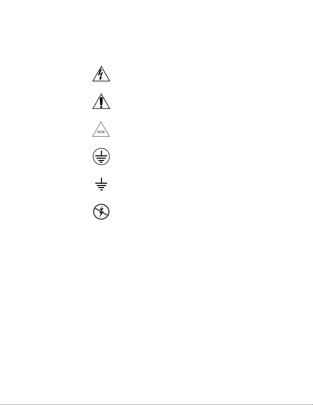
The following symbols may appear on the product:
Indicates that dangerous high voltage is present within the
equipment enclosure that may be of sufficient magnitude to
constitute a risk of electric shock.
Indicates that user, operator or service technician should refer
to product manual(s) for important operating, maintenance,
or service instructions.
This is a prompt to note fuse rating when replacing fuse(s).
The fuse referenced in the text must be replaced with one
having the ratings indicated.
Identifies a protective grounding terminal which must be connected to earth ground prior to making any
connections.
other equipment
Warnings
Identifies an external protective grounding terminal which
may be connected to earth ground as a supplement to an
internal grounding terminal.
Indicates that static sensitive components are present which
may be damaged by electrostatic discharge. Use anti-static
procedures, equipment and surfaces during servicing.
The following warning statements identify conditions or practices that can
result in personal injury or loss of life:
Dangerous voltage or current may be present — Disconnect power and remove
battery (if applicable) before removing protective panels, soldering, or
replacing components.
Do not service alone — Do not internally service this product unless another
person capable of rendering first aid and resuscitation is present.
Remove jewelry — Prior to servicing, remove jewelry such as rings, watches,
and other metallic objects.
Avoid exposed circuitry — Do not touch exposed connections, components or
circuitry when power is present.
12 Concerto — Installation and Service Manual
Page 13

Safety Summary
Use proper power cord — Use only the power cord supplied or specified for
this product.
Ground product — Connect the grounding conductor of the power cord to
earth ground.
Operate only with covers and enclosure panels in place — Do not operate this
product when covers or enclosure panels are removed.
Use correct fuse — Use only the fuse type and rating specified for this
product.
Use only in dry environment — Do not operate in wet or damp conditions.
Use only in non-explosive environment — Do not operate this product in an
explosive atmosphere.
High leakage current may be present — Earth connection of product is essential
before connecting power.
Dual power supplies may be present — Be certain to plug each power supply
cord into a separate branch circuit employing a separate service ground.
Disconnect both power supply cords prior to servicing.
Cautions
Double pole neutral fusing — Disconnect mains power prior to servicing.
Use proper lift points — Do not use door latches to lift or move equipment.
Avoid mechanical hazards — Allow all rotating devices to come to a stop before
servicing.
The following caution statements identify conditions or practices that can
result in damage to equipment or other property:
Use correct power source — Do not operate this product from a power source
that applies more than the voltage specified for the product.
Use correct voltage setting — If this product lacks auto-ranging power sup-
plies, before applying power ensure that the each power supply is set to
match the power source.
Provide proper ventilation — To prevent product overheating, provide equip-
ment ventilation in accordance with installation instructions.
Use anti-static procedures — Static sensitive components are present which
may be damaged by electrostatic discharge. Use anti-static procedures,
equipment and surfaces during servicing.
Do not operate with suspected equipment failure — If you suspect product damage
or equipment failure, have the equipment inspected by qualified service
personnel.
Concerto — Installation and Service Manual 13
Page 14

Safety Summary
Ensure mains disconnect — If mains switch is not provided, the power cord(s)
of this equipment provide the means of disconnection. The socket outlet
must be installed near the equipment and must be easily accessible. Verify
that all mains power is disconnected before installing or removing power
supplies and/or options.
Route cable properly — Route power cords and other cables so that they ar not
likely to be damaged. Properly support heavy cable bundles to avoid con
nector damage.
Use correct power supply cords — Power cords for this equipment, if provided,
meet all North American electrical codes. Operation of this equipment at
voltages exceeding 130 VAC requires power supply cords which comply
with NEMA configurations. International power cords, if provided, have
the approval of the country of use.
Use correct replacement battery — This product may contain batteries. To
reduce the risk of explosion, check polarity and replace only with the same
or equivalent type recommended by manufacturer. Dispose of used bat
teries according to the manufacturer’s instructions.
Troubleshoot only to board level — Circuit boards in this product are densely
populated with surface mount technology (SMT) components and applica
tion specific integrated circuits (ASICS). As a result, circuit board repair at
the component level is very difficult in the field, if not impossible. For war
ranty compliance, do not troubleshoot systems beyond the board level.
-
-
-
-
14 Concerto — Installation and Service Manual
Page 15

Sicherheit – Überblick
Lesen und befolgen Sie die wichtigen Sicherheitsinformationen dieses
Abschnitts. Beachten Sie insbesondere die Anweisungen bezüglich
Brand-, Stromschlag- und Verletzungsgefahren. Weitere spezifische, hier
nicht aufgeführte Warnungen finden Sie im gesamten Handbuch.
WARNUNG Alle Anweisungen in diesem Handbuch, die das Abnehmen der
Geräteabdeckung oder des Gerätegehäuses erfordern, dürfen nur von
qualifiziertem Servicepersonal ausgeführt werden. Um die
Stromschlaggefahr zu verringern, führen Sie keine Wartungsarbeiten
außer den in den Bedienungsanleitungen genannten Arbeiten aus, es sei
denn, Sie besitzen die entsprechende Qualifikationen für diese Arbeiten.
Sicherheit – Begriffe und Symbole
Safety Summary
In diesem Handbuch verwendete Begriffe
Sicherheitsrelevante Hinweise können in diesem Handbuch in der folgenden Form auftauchen:
WARNUNG Warnungen weisen auf Situationen oder Vorgehensweisen hin, die
Verletzungs- oder Lebensgefahr bergen.
VORSICHT Vorsichtshinweise weisen auf Situationen oder Vorgehensweisen hin, die zu
Schäden an Ausrüstungskomponenten oder anderen Gegenständen oder
zum zeitweisen Ausfall wichtiger Komponenten in der Arbeitsumgebung
führen können.
Hinweise am Produkt
Die folgenden Hinweise können sich am Produkt befinden:
GEFAHR — Wenn Sie diesen Begriff lesen, besteht ein unmittelbares Verlet-
zungsrisiko.
WARNUNG — Wenn Sie diesen Begriff lesen, besteht ein mittelbares Verlet-
zungsrisiko.
VORSICHT — Es besteht ein Risiko für Objekte in der Umgebung, den Mixer
selbst oder andere Ausrüstungskomponenten.
Concerto — Installation and Service Manual 15
Page 16
Safety Summary
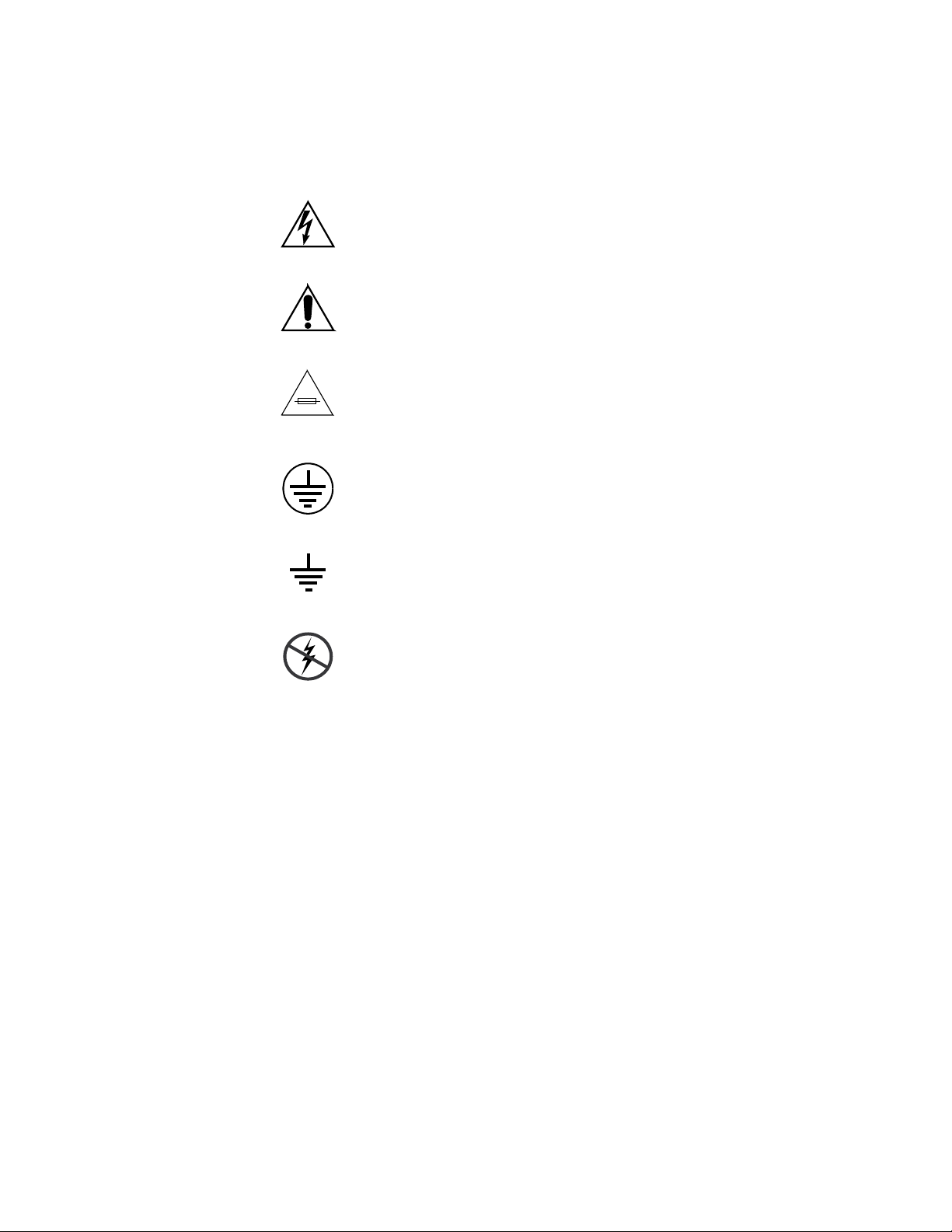
Symbole am Produkt
Die folgenden Symbole können sich am Produkt befinden:
Weist auf eine gefährliche Hochspannung im Gerätegehäuse
hin, die stark genug sein kann, um eine Stromschlaggefahr
darzustellen.
Weist darauf hin, dass der Benutzer, Bediener oder Servicetechniker wichtige Bedienungs-, W
weisungen in den Produkthandbüchern lesen sollte.
Dies ist eine Aufforderung, beim Wechsel von Sicherungen
auf deren Nennwert zu achten. Die im Text angegebene Sicherung muss durch eine Sicherung erse
angegebenen Nennwerte besitzt.
Weist auf eine Schutzerdungsklemme hin, die mit dem
Erdungskontakt verbunden werden muss, bevor weitere Ausrüstungskomponenten angeschlossen werden.
artungs- oder Servicean-
tzt werden, die die
Warnungen
Weist auf eine externe Schutzerdungsklemme hin, die als
Ergänzung zu einem internen Erdungskontakt an die Erde
angeschlossen werden kann.
Weist darauf hin, dass es statisch empfindliche Komponenten
gibt, die durch eine elektrostatische Entladung beschädigt
werden können. Verwenden Sie antistatische Prozeduren,
Ausrüstung und Oberflächen während der Wartung.
Die folgenden Warnungen weisen auf Bedingungen oder Vorgehensweisen
hin, die Verletzungs- oder Lebensgefahr bergen:
Gefährliche Spannungen oder Ströme — Schalten Sie den Strom ab, und ent-
fernen Sie ggf. die Batterie, bevor sie
oder Komponenten austauschen.
Servicearbeiten nicht alleine ausführen — Führen Sie interne Servicearbeiten nur
aus, wenn eine weitere Person anwesend ist, die erste Hilfe leisten und
Wiederbelebungsmaßnahmen einleiten kann.
Schutzabdeckungen abnehmen, löten
Schmuck abnehmen — Legen Sie vor Servicearbeiten Schmuck wie Ringe,
Uhren und andere metallische Objekte ab.
16 Concerto — Installation and Service Manual
Page 17

Safety Summary
Keine offen liegenden Leiter berühren — Berühren Sie bei eingeschalteter Strom-
zufuhr keine offen liegenden Leitungen, Komponenten oder Schaltungen.
Richtiges Netzkabel verwenden — Verwenden Sie nur das mitgelieferte Netzk-
abel oder ein Netzkabel, das den Spezifikationen für dieses Produkt
entspricht.
Gerät erden — Schließen Sie den Erdleiter des Netzkabels an den Erdung-
skontakt an.
Gerät nur mit angebrachten Abdeckungen und Gehäuseseiten betreiben — Schalten Sie
dieses Gerät nicht ein, wenn die Abdeckungen oder Gehäuseseiten entfernt
wurden.
Richtige Sicherung verwenden — Verwenden Sie nur Sicherungen, deren Typ
und Nennwert den Spezifikationen für dieses Produkt entsprechen.
Gerät nur in trockener Umgebung verwenden — Betreiben Sie das Gerät nicht in
nassen oder feuchten Umgebungen.
Gerät nur verwenden, wenn keine Explosionsgefahr besteht — Verwenden Sie dieses
Produkt nur in Umgebungen, in denen keinerlei Explosionsgefahr besteht.
Hohe Kriechströme — Das Gerät muss vor dem Einschalten unbedingt geerdet
werden.
Doppelte Spannungsversorgung kann vorhanden sein — Schließen Sie die beiden
Anschlußkabel an getrennte Stromkreise an. Vor Servicearbeiten sind beide
Anschlußkabel vom Netz zu trennen.
Zweipolige, neutrale Sicherung — Schalten Sie den Netzstrom ab, bevor Sie mit
den Servicearbeiten beginnen.
Fassen Sie das Gerät beim Transport richtig an — Halten Sie das Gerät beim Trans-
port nicht an Türen oder anderen beweglichen Teilen fest.
Gefahr durch mechanische Teile — Warten Sie, bis der Lüfter vollständig zum
Halt gekommen ist, bevor Sie mit den Servicearbeiten beginnen.
Vorsicht
Die folgenden Vorsichtshinweise weisen auf Bedingungen oder Vorgehensweisen hin, die zu Schäden an Ausrüstungskomponenten oder
anderen Gegenständen führen können:
Gerät nicht öffnen — Durch das unbefugte Öffnen wird die Garantie ungültig.
Richtige Spannungsquelle verwenden — Betreiben Sie das Gerät nicht an einer
Spannungsquelle, die eine höhere Spannung liefert als in den Spezifika
tionen für dieses Produkt angegeben.
Gerät ausreichend belüften — Um eine Überhitzung des Geräts zu vermeiden,
müssen die Ausrüstungskomponenten entsprechend den Installationsan
Concerto — Installation and Service Manual 17
-
-
Page 18

Safety Summary
weisungen belüftet werden. Legen Sie kein Papier unter das Gerät. Es
könnte die Belüftung behindern. Platzieren Sie das Gerät auf einer ebenen
Oberfläche.
Antistatische Vorkehrungen treffen — Es gibt statisch empfindliche Kompo-
nenten, die durch eine elektrostatische Entladung beschädigt werden können. Verwenden Sie antistatische Prozeduren, Ausrüstung und
Oberflächen während der Wartung.
CF-Karte nicht mit einem PC verwenden — Die CF-Karte ist speziell formatiert.
Die auf der CF-Karte gespeicherte Software könnte gelöscht werden.
Gerät nicht bei eventuellem Ausrüstungsfehler betreiben — Wenn Sie einen Produk-
tschaden oder Ausrüstungsfehler vermuten, lassen Sie die Komponente
von einem qualifizierten Servicetechniker untersuchen.
Kabel richtig verlegen — Verlegen Sie Netzkabel und andere Kabel so, dass Sie
nicht beschädigt werden. Stützen Sie schwere Kabelbündel ordnungs
gemäß ab, damit die Anschlüsse nicht beschädigt werden.
Richtige Netzkabel verwenden — Wenn Netzkabel mitgeliefert wurden, erfüllen
diese alle nationalen elektrischen Normen. Der Betrieb dieses Geräts mit
Spannungen über 130 V AC erfordert Netzkabel, die NEMA-Konfigura
tionen entsprechen. Wenn internationale Netzkabel mitgeliefert wurden,
sind diese für das Verwendungsland zugelassen.
-
-
Richtige Ersatzbatterie verwenden — Dieses Gerät enthält eine Batterie. Um die
Explosionsgefahr zu verringern, prüfen Sie die Polarität und tauschen die
Batterie nur gegen eine Batterie desselben Typs oder eines gleichwertigen,
vom Hersteller empfohlenen Typs aus. Entsorgen Sie gebrauchte Batterien
entsprechend den Anweisungen des Batterieherstellers.
Das Gerät enthält keine Teile, die vom Benutzer gewartet werden können.
Wenden Sie sich bei Problemen bitte an den nächsten Händler.
18 Concerto — Installation and Service Manual
Page 19

Consignes de sécurité
Il est recommandé de lire, de bien comprendre et surtout de respecter les
informations relatives à la sécurité qui sont exposées ci-après, notamment
les consignes destinées à prévenir les risques d’incendie, les décharges élec
triques et les blessures aux personnes. Les avertissements complémentaires, qui ne sont pas nécessairement repris ci-dessous, mais présents dans
toutes les sections du manuel, sont également à prendre en considération.
AVERTISSEMENT Toutes les instructions présentes dans ce manuel qui concernent
l’ouverture des capots ou des logements de cet équipement sont
destinées exclusivement à des membres qualifiés du personnel de
maintenance. Afin de diminuer les risques de décharges
électriques, ne procédez à aucune intervention d’entretien autre
que celles contenues dans le manuel de l’utilisateur, à moins que
vous ne soyez habilité pour le faire.
Safety Summary
-
Consignes et symboles de sécurité
Termes utilisés dans ce manuel
Les consignes de sécurité présentées dans ce manuel peuvent apparaître
sous les formes suivantes:
AVERTISSEMENT Les avertissements signalent des conditions ou des pratiques
susceptibles d’occasionner des blessures graves, voire même
fatales.
ATTENTION Les mises en garde signalent des conditions ou des pratiques
susceptibles d’occasionner un endommagement à l’équipement ou
aux installations, ou de rendre l’équipement temporairement non
opérationnel, ce qui peut porter préjudice à vos activités.
Signalétique apposée sur le produit
La signalétique suivante peut être apposée sur le produit:
DANGER — risque de danger imminent pour l’utilisateur.
AVERTISSEMENT — Risque de danger non imminent pour l’utilisateur.
MISE EN GARDE — Risque d’endommagement du produit, des installations
ou des autres équipements.
Concerto — Installation and Service Manual 19
Page 20
Safety Summary
Symboles apposés sur le produit
Les symboles suivants peut être apposés sur le produit:
Signale la présence d’une tension élevée et dangereuse dans le
boîtier de l’équipement ; cette tension peut être suffisante
pour constituer un r
Signale que l’utilisateur, l’opérateur ou le technicien de maintenance doit faire référence au(
naissance des instructions d’uti
d’entretien.
Il s’agit d’une invite à prendre note du calibre du fusible lors
du remplacement de ce dernier. Le fusible auquel il est fait
référence dans le texte doit être remplacé par un fusible du
même calibre.
Identifie une borne de protection de mise à la masse qui doit
être raccordée correctement avant de procéder au raccordement des autres équipements.
isque de décharge électrique.
x) manuel(s) pour prendre con-
lisation, de maintenance ou
Avertissements
Identifie une borne de protection de mise à la masse qui peut
être connectée en tant que borne de mise à la masse supplémentaire.
Signale la présence de composants sensibles à l’électricité statique et qui sont susceptibles d’ê
décharge électrostatique. Utilisez des procédures, des équipements et des surfaces antistatique
d’entretien.
Les avertissements suivants signalent des conditions ou des pratiques susceptibles d’occasionner des blessures graves, voire même fatales:
Présence possible de tensions ou de courants dangereux — Mettez hors tension,
débranchez et retirez la pile (le cas échéant) avant de déposer les couvercles
de protection, de défaire une soudure ou de remplacer des composants.
Ne procédez pas seul à une intervention d’entretien — Ne réalisez pas une interven-
tion d’entretien interne sur ce produit
pour fournir les premiers soins en cas d’accident.
si une personne n’est pas présente
tre endommagés par une
s durant les interventions
20 Concerto — Installation and Service Manual
Page 21

Safety Summary
Retirez tous vos bijoux — Avant de procéder à une intervention d’entretien,
retirez tous vos bijoux, notamment les bagues, la montre ou tout autre objet
métallique.
Évitez tout contact avec les circuits exposés — Évitez tout contact avec les connex-
ions, les composants ou les circuits exposés s’ils sont sous tension.
Utilisez le cordon d’alimentation approprié — Utilisez exclusivement le cordon
d’alimentation fourni avec ce produit ou spécifié pour ce produit.
Raccordez le produit à la masse — Raccordez le conducteur de masse du cordon
d’alimentation à la borne de masse de la prise secteur.
Utilisez le produit lorsque les couvercles et les capots sont en place — N’utilisez pas
ce produit si les couvercles et les capots sont déposés.
Utilisez le bon fusible — Utilisez exclusivement un fusible du type et du
calibre spécifiés pour ce produit.
Utilisez ce produit exclusivement dans un environnement sec — N’utilisez pas ce
produit dans un environnement humide.
Utilisez ce produit exclusivement dans un environnement non explosible — N’utilisez
pas ce produit dans un environnement dont l’atmosphère est explosible.
Mises en garde
Présence possible de courants de fuite — Un raccordement à la masse est indis-
pensable avant la mise sous tension.
Deux alimentations peuvent être présentes dans l’équipement — Assurez vous que
chaque cordon d’alimentation est raccordé à des circuits de terre séparés.
Débranchez les deux cordons d’alimentation avant toute intervention.
Fusion neutre bipolaire — Débranchez l’alimentation principale avant de pro-
céder à une intervention d’entretien.
Utilisez les points de levage appropriés — Ne pas utiliser les verrous de la porte
pour lever ou déplacer l’équipement.
Évitez les dangers mécaniques — Laissez le ventilateur s’arrêter avant de pro-
céder à une intervention d’entretien.
Les mises en garde suivantes signalent les conditions et les pratiques susceptibles d’occasionner des endommagements à l’équipement et aux installations:
N’ouvrez pas l’appareil — Toute ouverture prohibée de l’appareil aura pour
effet d’annuler la garantie.
Utilisez la source d’alimentation adéquate — Ne branchez pas ce produit à une
source d’alimentation qui utilise une tension supérieure à la tension nomi
nale spécifiée pour ce produit.
Concerto — Installation and Service Manual 21
-
Page 22

Safety Summary
Assurez une ventilation adéquate — Pour éviter toute surchauffe du produit,
assurez une ventilation de l’équipement conformément aux instructions
d’installation. Ne déposez aucun document sous l’appareil — ils peuvent
gêner la ventilation. Placez l’appareil sur une surface plane.
Utilisez des procédures antistatiques - Les composants sensibles à l’électricité
statique présents dans l’équipement sont susceptibles d’être endommagés
par une décharge électrostatique. Utilisez des procédures, des équipements
et des surfaces antistatiques durant les interventions d’entretien.
N’utilisez pas la carte CF avec un PC — La carte CF a été spécialement formatée.
Le logiciel enregistré sur la carte CF risque d’être effacé.
N’utilisez pas l’équipement si un dysfonctionnement est suspecté — Si vous sus-
pectez un dysfonctionnement du produit, faites inspecter celui-ci par un
membre qualifié du personnel d’entretien.
Acheminez les câbles correctement — Acheminez les câbles d’alimentation et les
autres câbles de manière à ce qu’ils ne risquent pas d’être endommagés.
Supportez correctement les enroulements de câbles afin de ne pas endom
mager les connecteurs.
-
Utilisez les cordons d’alimentation adéquats — Les cordons d’alimentation de cet
équipement, s’ils sont fournis, satisfont aux exigences de toutes les régle
mentations régionales. L’utilisation de cet équipement à des tensions
dépassant les 130
aux exigences des configurations NEMA. Les cordons internationaux, s’ils
sont fournis, ont reçu l’approbation du pays dans lequel l’équipement est
utilisé.
Utilisez une pile de remplacement adéquate — Ce produit renferme une pile. Pour
réduire le risque d’explosion, vérifiez la polarité et ne remplacez la pile que
par une pile du même type, recommandée par le fabricant. Mettez les piles
usagées au rebut conformément aux instructions du fabricant des piles.
Cette unité ne contient aucune partie qui peut faire l’objet d’un entretien
par l’utilisateur. Si un problème survient, veuillez contacter votre distribu
teur local.
V en c.a. requiert des cordons d’alimentation qui satisfont
-
-
22 Concerto — Installation and Service Manual
Page 23

Regulatory Notices
Certifications and Compliances
FCC Emission Control
This equipment has been tested and found to comply with the limits for a
Class A digital device, pursuant to Part 15 of the FCC Rules. These limits
are designed to provide reasonable protection against harmful interference
when the equipment is operated in a commercial environment. This equip
ment generates, uses, and can radiate radio frequency energy and, if not
installed and used in accordance with the instruction manual, may cause
harmful interference to radio communications. Operation of this equip
ment in a residential area is likely to cause harmful interference in which
case the user will be required to correct the interference at his own expense.
Changes or modifications not expressly approved by Grass Valley Group
can affect emission compliance and could void the user’s authority to
operate this equipment.
-
-
Canadian EMC Notice of Compliance
This digital apparatus does not exceed the Class A limits for radio noise
emissions from digital apparatus set out in the Radio Interference Regula
tions of the Canadian Department of Communications.
Le présent appareil numérique n’emet pas de bruits radioélectriques
dépassant les limites applicables aux appareils numeriques de la classe A
préscrites dans le Règlement sur le brouillage radioélectrique édicte par le
ministère des Communications du Canada.
EN55022 Class A Warning
For products that comply with Class A. In a domestic environment this
product may cause radio interference in which case the user may be
required to take adequate measures.
-
Concerto — Installation and Service Manual 23
Page 24

Regulatory Notices
Canadian Certified Power Cords
Canadian Certified AC Adapter
Laser Compliance
Laser Safety Requirements
Canadian approval includes the products and power cords appropriate for
use in the North America power network. All other power cords supplied
are approved for the country of use.
Canadian approval includes the AC adapters appropriate for use in the
North America power network. All other AC adapters supplied are
approved for the country of use.
The device used in this product is a Class 1 certified laser product. Operating this product outside specifications or altering from its original design
may result in hazardous radiation exposure, and may be considered an act
of modifying or new manufacturing of a laser product under U.S. regula
tions contained in 21CFR Chapter1, subchapter J or CENELEC regulations
in HD 482 S1. People performing such an act are required by law to recertify
and reidentify this product in accordance with provisions of 21CFR sub
chapter J for distribution within the U.S.A., and in accordance with
CENELEC HD 482 S1 for distribution within countries using the IEC 825
standard.
-
-
Laser Safety
Laser safety in the United States is regulated by the Center for Devices and
Radiological Health (CDRH). The laser safety regulations are published in
the “Laser Product Performance Standard,” Code of Federal Regulation
(CFR), Title 21, Subchapter J.
The international Electrotechnical Commission (IEC) Standard 825, “Radiation of Laser Products, Equipment Classification, Requirements and
User’s Guide,” governs laser products outside the United States. Europe
and member nations of the European Free trade Association fall under the
jurisdiction of the Comite European de Normalization Electrotechnique
(CENELEC).
For the CDRH: The radiant power is detected trough a 7 mm aperture at a
distance of 200 mm from the source focused through a lens with a focal
length of 100 mm.
24 Concerto — Installation and Service Manual
Page 25

FCC Emission Limits
Certification
Regulatory Notices
For IEC compliance: The radiant power is detected trough a 7 mm aperture
at a distance of 100 mm from the source focused through a lens with a focal
length of 100 mm.
This device complies with Part 15 of the FCC Rules. Operation is subject to
the following two conditions: (1) This device may not cause harmful inter
ference, and (2) this device must accept any interference received,
including interference that may cause undesirable operation. This device
has been tested and found to comply with FCC Part 15 Class B limits for a
digital device when tested with a representative laser-based fiber optical
system that complies with ANSI X3T11 Fiber Channel Standard.
Category Standard Designed/tested for compliance with:
Safety UL1950 Safety of Information Technology Equipment, including Electrical Busi-
ness Equipment (Second edition, 1993).
IEC 950 Safety of Information Technology Equipment, including Electrical Busi-
ness Equipment (Second edition, 1991).
CAN/CSA C22.2, No. 950-93 Safety of Information Technology Equipment, including Electrical Busi-
ness Equipment.
EN60950 Safety of Information Technology Equipment, including Electrical Busi-
ness Equipment.
-
Concerto — Installation and Service Manual 25
Page 26

Regulatory Notices
26 Concerto — Installation and Service Manual
Page 27

ESD Protection
Electronics today are more susceptible to electrostatic discharge (ESD)
damage than older equipment. Damage to equipment can occur by ESD
fields that are smaller than you can feel. Implementing the information in
this section will help you protect the investment that you have made in
purchasing Grass Valley equipment. This section contains Grass Valley’s
recommended ESD guidelines that should be followed when handling
electrostatic discharge sensitive (ESDS) items. These minimal recommen
dations are based on the information in the Sources of ESD and Risks area.
The information in Grounding Requirements for Personnel on page 29 is provided to assist you in selecting an appropriate grounding method.
Recommended ESD Guidelines
Follow these guidelines when handling Grass Valley equipment:
• Only trained personnel that are connected to a grounding system
should handle ESDS items.
• Do not open any protective bag, box, or special shipping packaging
until you have been grounded.
-
Note When a Personal Grounding strap is unavailable, as an absolute minimum,
touch a metal object that is touching the floor (for example, a table, frame, or
rack) to discharge any static energy before touching an ESDS item.
• Open the anti-static packaging by slitting any existing adhesive tapes.
Do not tear the tapes off.
• Remove the ESDS item by holding it by its edges or by a metal panel.
• Do not touch the components of an ESDS item unless it is absolutely
necessary to configure or repair the item.
• Keep the ESDS work area clear of all nonessential items such as coffee
cups, pens, wrappers and personal items as these items can discharge
static. If you need to set an ESDS item down, place it on an anti-static
mat or on the anti-static packaging.
Concerto — Installation and Service Manual 27
Page 28

ESD Protection
Sources of ESD and Risks
The following information identifies possible sources of electrostatic discharge and can be used to help establish an ESD policy.
Personnel
One of the largest sources of static is personnel. The static can be released
from a person’s clothing and shoes.
Environment
The environment includes the humidity and floors in a work area. The
humidity level must be controlled and should not be allowed to fluctuate
over a broad range. Relative humidity (RH) is a major part in determining
the level of static that is being generated. For example, at 10% - 20% RH a
person walking across a carpeted floor can develop 35kV; yet when the rel
ative humidity is increased to 70% - 80%, the person can only generate
1.5kV.
-
Static is generated as personnel move (or as equipment is moved) across a
floor’s surface. Carpeted and waxed vinyl floors contribute to static build
up.
Work Surfaces
Painted or vinyl-covered tables, chairs, conveyor belts, racks, carts, anodized surfaces, plexiglass covers, and shelving are all static generators.
Equipment
Any equipment commonly found in an ESD work area, such as solder
guns, heat guns, blowers, etc., should be grounded.
Materials
Plastic work holders, foam, plastic tote boxes, pens, packaging containers
and other items commonly found at workstations can generate static elec
tricity.
-
28 Concerto — Installation and Service Manual
Page 29

Grounding Requirements for Personnel
The information in this section is provided to assist you in selecting a
grounding method. This information is taken from ANSI/ESD S20.20-2007
(Revision of ANSI/ESD S20.20-1999).
Table 1. Product Qualification
Personnel Grounding Technical
Requirement
Wrist Strap System* ANSI/ESD S1.1 (Section 5.11) < 3.5 x 10⁷ ohm
Flooring / Footwear System – Method 1 ANSI/ESD STM97.1 < 3.5 x 10
Flooring / Footwear System – Method 2
(both required)
ANSI/ESD STM97.1
ANSI/ESD STM97.2
Product qualification is normally conducted during the initial selection of
ESD control products and materials. Any of the following methods can be
used: product specification review, independent laboratory evaluation, or
internal laboratory evaluation.
Test Method Required Limits
9
< 10
< 100 V
ESD Protection
7
ohm
ohm
Table 2. Compliance Verification
Personnel Grounding Technical
Requirement
Wrist Strap System* ESD TR53 Wrist Strap Section < 3.5 x 10⁷ ohm
Flooring / Footwear System – Method 1 ESD TR53 Flooring Section and ESD
Flooring / Footwear System – Method 2
(both required)
TR53 Footwear Section
ESD TR53 Flooring Section and ESD
TR53 Footwear Section
Test Method Required Limits
< 3.5 x 10
< 1.0 x 10
7
ohm
9
ohm
* For situations where an ESD garment is used as part of the wrist strap
grounding path, the total system resistance, including the person, garment,
7
and grounding cord, must be less than 3.5 x 10
ohm.
Concerto — Installation and Service Manual 29
Page 30

ESD Protection
30 Concerto — Installation and Service Manual
Page 31

System Description
The Concerto Multi-Format Routing switcher is a matrix-type video/
audio/data switching system designed for use in broadcast, teleproduc
tion, and networking facilities.
The module slots in the frame are not format sensitive. The slots are physically configured by plugging in any Concerto module and associated
backplane into any slot. Each module is a complete 32x32 matrix containing
inputs, outputs, and crosspoints. By inserting the modules in the frame in
different configurations, such as two digital video modules in adjoining
slots, matrices of 32x32 to 128x128 are created.
CAUTION If a module is plugged into an incompatible backplane it will cause damage.
Three rack frame versions are available:
Section 1
-
• 4 RU Concerto frame with two slots for modules. This chassis, which is
sometimes referred to as the “Concerto 64” frame, can use the lower
cost 64x32 modules.
• 7 RU Concerto frame with four slots for modules. This frame can be
loaded with any four modules, with the exceptions that only two HD
video modules can be installed when there are two other modules; or if
three HD video modules are installed then the fourth slot must be left
empty.
• 8 RU Concerto+ frame with four slots for modules. This frame can be
loaded with any combination of four modules including four HD video
modules.
Module signal formats include:
• Analog (audio and video),
1
• Digital (AES audio, SD, HD and 3GB/s video
• Data (Time Code and Port) modules.
Two video reference inputs, allow assignment of both PAL and NTSC references to the same frame.
In addition to supporting up to 3Gb/S , the module also supports 270 Mb/
S "standard rate" SDI/DVB-ASI as well as 1.5Gb/S HD SDI.
), and
1.
For a discussion of recent modifications to the HD video module and rear panel, see page 152.
Concerto — Installation and Service Manual 31
Page 32

Section 1 — System Description
The frame is equipped with a 48 VDC external power connector.
Mixed Module Matrices
The Analog Audio module has Analog to Digital and Digital to Analog
converters built into the module. This allows the configuration of physical
matrices that contain Analog Audio modules and Digital Audio modules.
These mixed audio matrices work the same as regular matrices with all
inputs available to all outputs.
When configuring a level or matrix that contains both Analog Audio
modules and AES Digital Audio modules use settings for AES Digital
Audio for all the modules in the grouping.
The Digital Video modules 3 Gb/s, SD and HD can be combined into a
physical matrix. All SD video signals can be routed through any module
making SD video available to all inputs and outputs. The HD signal (1.5
Gbs) can be routed through the HD and 3Gb/s modules. 3Gb/s signals can
only be routed through the 3Gb/s module.
CAUTION The maximum number of HD modules that can be in a 7 RU Concerto frame
is three; in which case the fourth slot has to remain empty. If two HD modules
are used then the other two slots can be loaded with any of the non HD modules.
When configuring a level or matrix that contains both SD and HD Digital
Video modules use settings for SD Digital Video for all the modules in the
grouping. The Analog Video module cannot be mixed with Digital Video
modules in the same level but can be in the same frame as a separate level.
The Port module can be used as either a Time Code module or a Port
module. Time Code and Port cannot be mixed in the same level.
Controller Module Identification
Controller modules (CM) are designed to work in pairs (one primary, one
backup) to provide failure resistance. The primary CM provides all
required functions; the backup is ready to take over should the primary
unit fail. Control logic facilitates the orderly change of control between the
two modules and ensures that only one module at a time controls the
external serial busses.
Control consists of the messages created and sent to the CM to set matrix
crosspoints, and the return messages from the CM containing true tally
status back to the control system.
32 Concerto — Installation and Service Manual
Page 33

Controller Module Identification
0_
18765432
ON
18765432ON18765432
ON
18765432
ON
18765432
ON
18765432
ON
18765432
ON
18765432
ON
18765432
ON
PWR
OK
DONEACT
GND
+5V
ERROR
TC2
PRES
BUSY
48K
PRES
LINK
SYNC
ERR
RECV
VI 2
PRES
XMIT
VI 1
PRES
CLEAR MEM
RESET
TX
RXFAST COL TC1
PRES
+2.5V
+3.3V
A_LEVEL
B_LEVEL
A_OPTIONS
C_LEVEL
D_LEVEL
B_OPTIONS
C_OPTIONS
D_OPTIONS
MODE/IN
SEL
S11
S12
S13
A
B
C
D
E
F
G
H
A
B
C
D
E
F
G
H
A
B
C
D
E
F
G
H
A
B
C
D
E
F
G
H
MATRIX MAPCONFIG
GRASS VALLEY GROUP
CRS2001 CONTROLLER
671-6381 –
MADE IN U.S.A.
GRASS VALLEY GROUP
CRS2001 FAST CONTROLLER
671-6434 –
MADE IN U.S.A.
GRASS VALLEY GROUP CRS-MC-C2
MADE IN U.S.A.
671-6495
The CMs can be inserted into a powered frame. To ensure that the system
power supply is not disturbed, a pre-charge resistor is connected in series
with one of the rear connector pins. The corresponding pin on the back
plane connector is longer than any of the other power pins. This allows the
pre-charge pin to make connection before the others.
Vertical interval reference is required for Crosspoint switching tasks. This
is an analog video input which can be NTSC or PAL. This input is processed
to extract vertical sync and odd/even field (if any) information. A pre
defined programmable logic device (PLD) is used to create a switching
strobe that is offset into line 10 for NTSC or line 6 for PAL. A video presence
detector interrupts the processor if the video reference is missing. If this ref
erence is missing a fake sync is generated at a default asynchronous
interval.
Concerto has three Controller modules. Two of the modules are Ethernet
only. One Ethernet Controller is labeled
with an Ethernet interface of10Base-T and the other is labeled
CONTROLLER 671-6434-xx
third Controller is labeled
with an Ethernet interface of 10/100Base-T. The
CRS-MC-C2 671-6495-xx and can be set to allow
CRS2001 CONTROLLER 671-6381-xx
CRS2001 FAST
either Ethernet or Crosspoint Bus interface control. Do not mix Controller
types in a single matrix. See
Figure 1 for help in identifying Controllers; see
Figure 79 on page 141 for the 3Gb/s board.
-
Figure 1. Example of Controller Module Identification Location
Concerto — Installation and Service Manual 33
Page 34

Section 1 — System Description
32 Inputs
(1-32)
from Slot 1
backplane
Input (1-32)
Distribution
to Slots
2, 3, & 4
32 Inputs
(33-64)
from Matrix 2
32 Inputs
(97-128)
from Matrix 4
32 Inputs
(65-96)
from Matrix 3
32 Outputs
(1-32)
to Slot 1
backplane
128x32
Crosspoint
Matrix
32x1
Monitor
Crosspoint
Input
Equalization
Output
Reclocking
8138_00_62r0
Module Configuration
Each module receives 32 inputs from the backplane associated with the slot
position of the module. Each module delivers 32 outputs to the backplane
associated with the slot position of the module. In
slot position 1 (top position) is receiving Inputs 1-32 from the backplane in
slot position 1. Because
available to the module via the Interconnect module. The module can now
deliver any of the Sources connected to Inputs 1-128 to the Output connec
tors 1-32 on the backplane in slot position 1.
Figure 2. Block Diagram for Module in Slot 1 (Top) in 128x128 Matrix
Figure 2, the module in
Figure 2 shows a 128x128 matrix, Inputs 33-128 are
-
The Analog Audio module has dual Inputs and Outputs to accommodate
the Left and Right channels. These dual connections are labeled on the
backplane using a 1A/1B format. The default is to software configure the
1A (Left) and 1B (Right) channels as a stereo signal. AES Audio has single
Inputs and Outputs where the default is to software configure each con
-
nector as a stereo signal.
The stereo channels can be configured to switch separately as mono signals.
The smallest mono matrix is a single module of 64x64 and the largest is
512x512 using two Concerto frames.
The module receives 64 inputs from the backplane associated with the slot
position of the module. Each module delivers 64 outputs to the backplane
associated with the slot position of the module. In
Figure 3, the module in
slot position 1 is receiving Inputs 1A/1B-32A/32B from the backplane in
slot position 1.
Figure 3 shows a 256x256 matrix where Inputs 33A/33B-
128A/128B are available to the module via the Interconnect module. The
module can now deliver any of the Sources connected to Inputs 1A/1B128A/128B to the Output connectors 1A/1B-32A/32B on the backplane in
slot position 1.
34 Concerto — Installation and Service Manual
Page 35

Module Identification
64 Inputs
(1A/1B to
32A/32B)
from Slot 1
backplane
Input (1A/1B to
32A/32B) Distribution
to Slots 2, 3, & 4
64 Inputs
(33A/33B to 64A/64B)
from Matrix 2
64 Inputs
(97A/97B to 128A/128B)
from Matrix 4
64 Inputs
(65A/65B to 96A/96B)
from Matrix 3
64 Outputs
(1A/1B to
32A/32B)
to Slot 1
backplane
Time
Division
Multiplexing
256x64
64x1
Monitor
Crosspoint
A to D
Converter
D to A
Converter
8138_00_63r0
Module Identification
Figure 3. Block Diagram for Module in Slot 1 in Analog Audio Mono 256x256 Matrix
The modules Crosspoint configuration can be 128x32, 64x32, or 32x32. The
64x32 Crosspoint configuration will allow two modules to create a 64x64
matrix but will not allow larger matrices. The 64x32 Crosspoint modules
can only be used in slots 1 (top) and 2 or slots 3 and 4 of the 7 RU Concerto
or 8 RU Concerto+ frames to create 64x64 matrices. The 32x32 Crosspoint
configuration modules cannot be combined into larger matrices but can be
used in all of the Concerto frames. The Analog audio matrices also have
three Maximum Input Level specifications +24 dBu, +18 dBu, and +15 dBu.
The attributes of each module are identified by the last two digits of the
part number.
Ta bl e 3 identifies Analog video modules.
Table 3. Analog Video Modules 671-6369-##
## Range Matrix Size Modules
00-49 128x128 4
96x96 3
64x64 2
32x32 1
50-79 64x64
80-99 32x32 1
a
If a 7 RU Concerto or 8 RU Concerto+ frame is used to create this matrix the modules
Concerto — Installation and Service Manual 35
must be placed in slots 1 and 2 or slots 3 and 4
a
32x32 1
2
Page 36

Section 1 — System Description
Ta bl e 4 identifies SD digital video modules.
Table 4. SD Digital Video Modules 671-6372-##
00-49 128x128 4
50-79 64x64
80-99 32x32 1
a
If a 7 RU Concerto or 8 RU Concerto+ frame is used to create this matrix the modules
must be placed in slots 1 and 2 or slots 3 and 4
Ta bl e 5 identifies HD digital video modules.
Table 5. HD Video Modules 691-0072-##
## Range Matrix Size Modules Comments
00-49 128x128 4 Must use the 128x128 Concerto+ frame for this matrix.
50-79 64x64
80-99 32x32 1 -
a
If a 7 RU Concerto or 8 RU Concerto+ frame is used to create this matrix the modules must be placed in slots 1 and 2 or
slots 3 and 4
## Range Matrix Size Modules
96x96 3
64x64 2
32x32 1
a
32x32 1
96x96 3 If 128x128 Concerto frame is used for this matrix the fourth slot has
64x64 2 -
32x32 1 -
a
32x32 1 -
2-
to remain empty.
2
Ta bl e 7 identifies AES digital audio modules.
Table 6. AES Digital Audio Modules 671-6371-##
## Range Matrix Size Modules
00-49 128x128 4
96x96 3
64x64 2
32x32 1
50-79 64x64
80-99 32x32 1
a
If a 7 RU Concerto or 8 RU Concerto+ frame is used to create this matrix the modules
must be placed in slots 1 and 2 or slots 3 and 4
a
32x32 1
2
36 Concerto — Installation and Service Manual
Page 37

Module Identification
Ta bl e 7 identifies Analog audio modules.
Table 7. Analog Audio Modules 671-6370-##
## Range Maximum dBu Level Matrix Size Modules
00-24 +24 dBu 128x128 4
96x96 3
64x64 2
32x32 1
25-49 +18 dBu 128x128 4
96x96 3
64x64 2
32x32 1
50-60 +15 dBu 128x128 4
96x96 3
64x64 2
32x32 1
61-70 +24 dBu 64x64
71-80 +18 dBu 64x64
81-90 +24 dBu 32x32 1
91-99 +18 dBu 32x32 1
a
If a 7 RU Concerto or 8 RU Concerto+ frame is used to create this matrix the modules must be placed in slots 1 and 2 or
slots 3 and 4
a
32x32 1
a
32x32 1
2
2
Concerto — Installation and Service Manual 37
Page 38

Section 1 — System Description
Optimum Matrix Configurations
Optimum performance is achieved by positioning the modules in the
frame using the top to bottom priority shown in
Note This hierarchy is required for interfacing to Jupiter Control Systems.
Table 8. Top-to-bottom Module Positions
Module Abbreviation
Analog Video AV
Digital Video (SD, HD, or 3Gb/s) DV
Analog Audio AA
Digital Audio (AES) DA
Data (Time Code or Port) TCP
CAUTION The maximum number of HD modules that can be in a 7 RU Concerto frame
is three in which case the fourth slot has to remain empty. If two HD modules
are used then the other two slots can be loaded with any of the non HD modules.
Ta bl e 8.
Note Because the 8 RU Concerto+ frame provides additional power and cooling
capacity when compared to the 7 RU frame, there are no restrictions on the
number of HD video modules in 8 RU frames.
The following are general guidelines:
• Empty slots need to be identified for their future use, such as HD Video,
• All modules that are in the same level must be next to each other in the
frame,
• The preferred hierarchy between SD and HD Video modules in the
same frame is to place the SD modules before the HD modules. If you
have a frame with two SD modules and two HD modules, place the SD
modules in slots 1 (top) and 2, and the HD modules in slots 3 and 4, and
• There is no preferred hierarchy between Time Code and Port modules
in the same frame.
38 Concerto — Installation and Service Manual
Page 39

7 RU Concerto / 8 RU Concerto+ Frames
32x32 / 96x96
Ta bl e 9 and Figure 4 show optimum module placement options for creating
a single 32x32 matrix and a three module 96x96 matrix. In Option 1, you can
use 3 SD Video modules or a combination of 1 or 2 HD Video modules with
SD Video modules. There are four variations shown (options 11 to 14) for a
96x96 matrix using mixed audio. Option 6 uses all audio modules but the
inputs and outputs of the two types of audio are kept separate. In
the Analog to Digital and Digital to Analog converters are shown in the
mixed audio matrices. Additional combinations can be created using
mixed audio, mixed video, or mixed data modules.
Table 9. Examples of Optimum Configurations (32x32 and 96x96)
One 32x32 Matrix and One 96x96 Matrix
a
Slot
Position
a
For this option 1 or 2 HD video modules can be used with SD video modules to create a 96x96 Digital Video matrix.
Slot
Position
Option 1
Modules
1 AVAVAVAVDVDVDV32x32
2 DVAADATCPAADATCP
4 DVAADATCPAADATCP
Option 8
Modules
1 AAAADAAVDVAVDV32x32
2 DATCPTCPAAAAAAAA
4 DATCPTCPDADADADA
Option 2
Modules
Option 9
Modules
Option 3
Modules
One 32x32 Matrix and One 96x96 Matrix
Option 10
Modules
7 RU Concerto / 8 RU Concerto+ Frames
Option 4
Modules
Option 11
Modules
Option 5
Modules
Option 12
Modules
Option 6
Modules
Option 13
Modules
Option 7
Modules
Option 14
Modules
Figure 4
Matrix
Size
96x963 DVAADATCPAADATCP
Matrix
Size
96x963DATCPTCPAAAADADA
Concerto — Installation and Service Manual 39
Page 40

Section 1 — System Description
8138_00_48r0
Inputs 1-32 Outputs 1-32
Xpt (In=1-32,
Out=1-32)
Inputs 65-96
Outputs 65-96
Xpt (In=1-96,
Out=1-32)
Xpt (In=1-96,
Out=33-64)
Xpt (In=1-96,
Out=65-96)
Inputs 1-32
A to D Conv.
Inputs 33-64
A to D Conv.
Outputs 33-64
D to A Conv.
Outputs 1-32
D to A Conv.
Signal Flow for Options 11 and 12
Power
Supply 2
Controller 1
Controller 2
Power
Supply 1
Input 1-32 Xpt (In=1-32, Out=1-32) Output 1-32
Input 65-96 Xpt (In=1-96, Out=65-96) Output 65-96
Input 33-64 Xpt (In=1-96, Out=33-64) Output 33-64
Input 1-32 Xpt (In=1-96, Out=1-32) Output 1-32
96x96
Matrix
32x32
Matrix
8138_00_45r0
Inputs 1-32 Outputs 1-32
Xpt (In=1-32,
Out=1-32)
Inputs 1-32
Outputs 1-32
Inputs 33-64 Outputs 33-64
Inputs 65-96
Outputs 65-96
Xpt (In=1-96,
Out=1-32)
Xpt (In=1-96,
Out=33-64)
Xpt (In=1-96,
Out=65-96)
8138_00_46r0
Inputs 1-32 Outputs 1-32
Xpt (In=1-32,
Out=1-32)
Inputs 33-64
Outputs 33-64
Inputs 65-96
Outputs 65-96
Xpt (In=1-96,
Out=1-32)
Xpt (In=1-96,
Out=33-64)
Xpt (In=1-96,
Out=65-96)
Inputs 1-32
A to D Conv.
D to A Conv.
Outputs 1-32
Signal Flow for Options 1 to 10
Signal Flow for Options 13 and 14
Figure 4. One 32x32 and One 96x96 Module Configuration and Signal Flow
Ta bl e 10 shows the Jupiter interface settings. Options 11 to 14 use mixed
modules AA and DA to create a 96x96 matrix level that is set as AES audio.
The numbers shown for the DIP switch banks indicate which of the eight
switches should be set in the
Table 10. Rotary and DIP Switch Settings for Jupiter Interface
1 2 3 4 5 6 7 8 9 10 11 12 13 14
Rotary S12 11111111111111
Rotary S13 03373374AA3333
A_LEVEL 1 1 1 1 1, 2, 3 1, 2, 3 1, 2, 3 2 2 6 1 1, 2, 3 1 1, 2, 3
A_OPTIONS--------------
Switch
40 Concerto — Installation and Service Manual
B_LEVEL 1, 2, 3 2 6 5 2 6 1, 2 6 5 1, 2 6 6 6 6
B_OPTIONS------1--1----
C_LEVEL 1, 2, 3 2 6 5 2 6 1, 2 6 5 1, 2 6 6 6 6
C_OPTIONS------1--1----
D_LEVEL 1, 2, 3 2 6 5 2 6 1, 2 6 5 1, 2 6 6 6 6
D_OPTIONS------1--1----
On position.
Jupiter Settings for Options from Table 9
DIP Switches set to ON Position
Page 41

64x64 / 64x64
Ta bl e 11 and Figure 5 show optimum module placement options for cre-
ating a pair of two module 64x64 matrices. There are two variations shown
(options 5 and 9) for a lower 64x64 matrix using mixed audio. Option 9 uses
all audio modules but the inputs and outputs of the two types of audio are
kept separate. In
verters are shown in the mixed audio matrices. Additional combinations
can be created using mixed audio, mixed video, or mixed data
modules.
Table 11. Examples of Optimum Matrix Configurations (64x64 and 64x64)
Slot
Position
1 AVAVAVAVAVDV
2 AVAVAVAVAVDV
3 DVAADATCPAAAA
4 DVAADATCPDAAA
Option 1
Modules
7 RU Concerto / 8 RU Concerto+ Frames
Figure 5 the Analog to Digital and Digital to Analog con-
Two 64x64 Matrices
Option 2
Modules
Option 3
Modules
Option 4
Modules
Option 5
Modules
Option 6
Modules
Matrix
Size
64x64
64x64
Two 64x64 Matrices
Slot
Position
Option 7
Modules
1 DVDVAAAADA
2 DVDVAAAADA
3 DA TCP DA TCP TCP
4 DA TCP DA TCP TCP
Option 8
Modules
Option 9
Modules
Option 10
Modules
Option 11
Modules
Matrix
Size
64x64
64x64
Concerto — Installation and Service Manual 41
Page 42
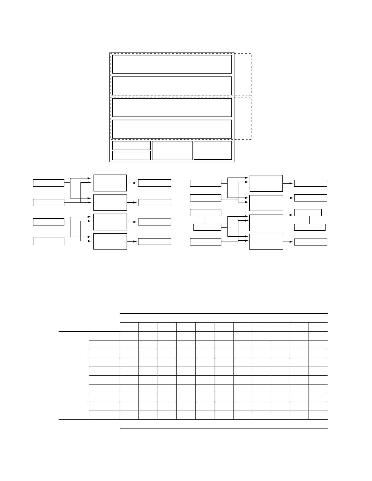
Section 1 — System Description
8138_00_49r0
Inputs 1-32
Outputs 1-32
Xpt (In=1-64,
Out=1-32)
Inputs 33-64
Inputs 33-64
Outputs 33-64
Xpt (In=1-64,
Out=33-64)
Xpt (In=1-64,
Out=1-32)
Xpt (In=1-64,
Out=33-64)
Inputs 1-32
A to D Conv.
D to A Conv.
Outputs 1-32
Outputs 33-64
Signal Flow for Option 5
8138_00_33r0
64x64
Matrix
64x64
Matrix
Power
Supply 2
Controller 1
Controller 2
Power
Supply 1
Input 33-64 Xpt (In=1-64, Out=33-64) Output 33-64
Input 1-32 Xpt (In=1-64, Out=1-32) Output 1-32
Input 33-64 Xpt (In=1-64, Out=33-64) Output 33-64
Input 1-32 Xpt (In=1-64, Out=1-32) Output 1-32
8138_00_44r0
Inputs 1-32 Outputs 1-32
Xpt (In=1-64,
Out=1-32)
Inputs 1-32
Outputs 1-32
Xpt (In=1-64,
Out=1-32)
Inputs 33-64
Outputs 33-64
Xpt (In=1-64,
Out=33-64)
Xpt (In=1-64,
Out=33-64)
Inputs 33-64 Outputs 33-64
Signal Flow for Options 1 to 4, and 6 to 11
Figure 5. Two 64x64 Module Configuration and Signal Flow
Ta bl e 12 shows the Jupiter interface settings. Options 4, 10, and 11 show set-
tings for Port modules, and Option 8 shows the settings for Time Code. The
numbers shown for the DIP switch banks indicate which of the eight
switches should be set in the
Table 12. Rotary and DIP Switch Settings for Jupiter Interface
1234567891011
Rotary S1222222222222
Rotary S1302262226499
A_LEVEL 1 1 1 1 1 1, 2, 3 1, 2, 3 1, 2, 3 2 2 6
A_OPTIONS-----------
Switches
42 Concerto — Installation and Service Manual
B_LEVEL 1 1 1 1 1 1, 2, 3 1, 2, 3 1, 2, 3 2 2 6
B_OPTIONS-----------
C_LEVEL 1, 2, 3 2 6 5 6 2 6 1, 2 6 5 5
C_OPTIONS-------1---
D_LEVEL 1, 2, 3 2 6 5 6 2 6 1, 2 6 5 5
D_OPTIONS-------1---
On position.
Jupiter Settings for Options from Table 11
DIP Switches set to ON Position
Page 43

7 RU Concerto / 8 RU Concerto+ Frames
8138_00_36r0
Power
Supply 2
Controller 1
Controller 2
Power
Supply 1
Input 65-96 Xpt (In=1-96, Out=65-96) Output 65-96
Input 33-64 Xpt (In=1-96, Out=33-64) Output 33-64
Input 1-32 Xpt (In=1-96, Out=1-32) Output 1-32
96x96
Matrix
Input 1-32 Xpt (In=1-32, Out=1-32) Output 1-32
32x32
Matrix
8138_00_54r0
Inputs 1-32
Outputs 1-32
Inputs 1-32 Outputs 1-32
Xpt (In=1-32,
Out=1-32)
Inputs 33-64 Outputs 33-64
Inputs 65-96
Outputs 65-96
Xpt (In=1-96,
Out=1-32)
Xpt (In=1-96,
Out=33-64)
Xpt (In=1-96,
Out=65-96)
Signal Flow for Options 1 to 9
96x96 / 32x32
Ta bl e 13 and Figure 6 show optimum module placement options for cre-
ating a three module 96x96 matrix and a single module 32x32 matrix.
Options 5, 6, and 7, you can use 3 SD Video modules or a combination of 1
or 2 HD Video modules with SD Video modules. Additional combinations
can be created using mixed audio, mixed video, or mixed data modules.
Table 13. Examples of Optimum Matrix Configurations (96x96 and 32x32)
One 96x96 Matrix and One 32x32 Matrix
a
Slot
Position
a
For this option 1 or 2 HD video modules can be used with SD video modules to create a 96x96 Digital Video matrix.
Option 1
Modules
1 AVAVAVAV DV DV DV AAAA
3 AVAVAVAV DV DV DV AAAA
4 DV AA DA TCP AA DA TCP DA TCP 32x32
Option 2
Modules
Option 3
Modules
Option 4
Modules
Option 5
Modules
Option 6a
Modules
Figure 6. One 96x96 and One 32x32 Module Configuration and Signal Flow
Option 7a
Modules
Option 8
Modules
Option 9
Modules
Matrix
Size
96x962 AVAVAVAV DV DV DV AAAA
Concerto — Installation and Service Manual 43
Page 44

Section 1 — System Description
Ta bl e 14 shows the Jupiter interface settings. Options 4 and 9 show settings
for Port modules, and Option 7 shows Time Code. The numbers shown for
the DIP switch banks indicate which of the eight switches should be set in
the
Table 14. Rotary and DIP Switch Settings for Jupiter Interface
Switches
On position.
Jupiter Settings for Options from Table 13
123456789
Rotary S12333333333
Rotary S13011511548
A_LEVEL 1 1 1 1 1, 2, 3 1, 2, 3 1, 2, 3 2 2
A_OPTIONS---------
B_LEVEL 1 1 1 1 1, 2, 3 1, 2, 3 1, 2, 3 2 2
B_OPTIONS---------
C_LEVEL 1 1 1 1 1, 2, 3 1, 2, 3 1, 2, 3 2 2
C_OPTIONS---------
D_LEVEL 1, 2, 3 2 6 5 2 6 1, 2 6 5
D_OPTIONS - - - - - - 1 - -
DIP Switches set to ON Position
128x128
Ta bl e 15 and Figure 7 show optimum module placement options for cre-
ating a single four module 128x128 matrix. There are three variations
shown (options 5 to 7) for a 128x128 matrix using mixed audio. In
the Analog to Digital and Digital to Analog converters are shown in the
mixed audio matrices. Additional combinations can be created using either
mixed audio, mixed video, or mixed data modules.
Table 15. Examples of Optimum Matrix Configurations (128x128)
One 128x128 Matrix
a
Slot
Position
a
For this option 1 or 2 HD or 3Gb/s video modules can be used with SD video modules to create a 128x128 Digital Video matrix.
b
All modules are Time Code.
c
All modules are Port
Option 1
Modules
1 AV DV AADAAAAAAATCPTCP
2 AV DV AADAAAAADATCPTCP
3 AV DV AADAAADADATCPTCP
4 AV DV AADADADADATCPTCP
Option 2
Modules
Option 3
Modules
Option 4
Modules
Option 5
Modules
Option 6
Modules
Option 7
Modules
Option 8b
Modules
Option 9c
Modules
Figure 7
Matrix
Size
128x128
44 Concerto — Installation and Service Manual
Page 45

7 RU Concerto / 8 RU Concerto+ Frames
8138_00_50r0
Xpt (In=1-128,
Out=1-32)
Inputs 97-128
Outputs 97-128
Xpt (In=1-128,
Out=33-64)
Xpt (In=1-128,
Out=65-96)
Xpt (In=1-128,
Out=97-128)
Inputs 33-64
A to D Conv.
Inputs 65-96
A to D Conv.
Outputs 65-96
D to A Conv.
Outputs 33-64
D to A Conv.
Outputs 1-32
D to A Conv.
Inputs 1-32
A to D Conv.
Signal Flow for Option 5
8138_00_31r0
128x128
Matrix
Power
Supply 2
Controller 1
Controller 2
Power
Supply 1
Input 97-128 Xpt (In=1-128, Out=97-128) Output 97-128
Input 65-96 Xpt (In=1-128, Out=65-96) Output 65-96
Input 33-64 Xpt (In=1-128, Out=33-64) Output 33-64
Input 1-32 Xpt (In=1-128, Out=1-32) Output 1-32
8138_00_53r0
Inputs 97-128 Outputs 97-128
Xpt (In=1-128,
Out=97-128)
Xpt (In=1-128,
Out=1-32)
Outputs 1-32Inputs 1-32
Xpt (In=1-128,
Out=65-96)
Outputs 65-96Inputs 65-96
Xpt (In=1-128,
Out=33-64)
Outputs 33-64Inputs 33-64
Signal Flow for Options 1 to 4, 8, 9
8138_00_51r0
Xpt (In=1-128,
Out=1-32)
Inputs 97-128
Outputs 97-128
Xpt (In=1-128,
Out=33-64)
Xpt (In=1-128,
Out=65-96)
Xpt (In=1-128,
Out=97-128)
Inputs 33-64
A to D Conv.
Outputs 65-96
D to A Conv.
Outputs 33-64
Outputs 1-32
D to A Conv.
Inputs 1-32
A to D Conv.
Inputs 65-96
Signal Flow for Option 6
8138_00_52r0
Xpt (In=1-128,
Out=1-32)
Inputs 97-128
Outputs 97-128
Xpt (In=1-128,
Out=33-64)
Xpt (In=1-128,
Out=65-96)
Xpt (In=1-128,
Out=97-128)
Outputs 65-96
Outputs 33-64
Outputs 1-32
D to A Conv.
Inputs 1-32
A to D Conv.
Inputs 65-96
Inputs 33-64
Signal Flow for Option 7
Figure 7. 128x128 Module Configuration and Signal Flow
Concerto — Installation and Service Manual 45
Page 46

Section 1 — System Description
Ta bl e 16 shows the Jupiter interface settings. Option 8 shows settings for
Time Code modules, and Option 9 shows Port. The numbers shown for the
DIP switch banks indicate which of the eight switches should be set in the
On position.
Table 16. Rotary and DIP Switch Settings for Jupiter Interface
Switches
a
Mixed Audio modules use AES Digital Audio as level.
b
All modules Time Code.
c
All modules Port.
Jupiter Settings for Options from Table 15
12345
Rotary S12000000000
Rotary S130044444EE
A_LEVEL 1 1, 2, 3 2 6 6 6 6 1, 2 5
A_OPTIONS-------1-
B_LEVEL 1 1, 2, 3 2 6 6 6 6 1, 2 5
B_OPTIONS-------1-
C_LEVEL 1 1, 2, 3 2 6 6 6 6 1, 2 5
C_OPTIONS - - - - - - - 1 -
D_LEVEL 1 1, 2, 3 2 6 6 6 6 1, 2 5
D_OPTIONS - - - - - - - 1 -
DIP Switches set to ON Position
a
a
6
a
7
b
8
c
9
46 Concerto — Installation and Service Manual
Page 47

32x32 / 32x32 / 64x64
Ta bl e 17 and Figure 8 show optimum module placement options for cre-
ating a two single module 32x32 matrices and a two module 64x64 matrix.
There is one variation shown (option4) for a 64x64 matrix using mixed
audio. In
are shown in the mixed audio matrices. Additional combinations can be
created using either mixed audio, mixed video, or mixed data modules.
Table 17. Examples of Optimum Matrix Configurations (32x32,32x32, and 64x64)
Slot
Position
Slot
Position
Figure 8 the Analog to Digital and Digital to Analog converters
Option 1
Modules
1 AVAVAVAVAVAV32x32
2 DVDVDVDVAA AA32x32
3AADATCPAADATCP
4 AA DA TCP DA DA TCP
Option 7
Modules
1 AV DV DV DV AA 32x32
2 DA AA AA DA DA 32x32
3 TCP DA TCP TCP TCP
4 TCP DA TCP TCP TCP
7 RU Concerto / 8 RU Concerto+ Frames
Two 32x32 Matrices and One 64x64 Matrix
Option 2
Modules
Two 32x32 Matrices and One 64x64 Matrix
Option 8
Modules
Option 3
Modules
Option 9
Modules
Option 4
Modules
Option 10
Modules
Modules
Option 11
Modules
Option 5
Option 6
Modules
Matrix
Size
64x64
Matrix
Size
64x64
Concerto — Installation and Service Manual 47
Page 48

Section 1 — System Description
8138_00_38r0
Power
Supply 2
Controller 1
Controller 2
Power
Supply 1
Input 33-64 Xpt (In=1-96, Out=33-64) Output 33-64
Input 1-32 Xpt (In=1-96, Out=1-32) Output 1-32
64x64
Matrix
Input 1-32 Xpt (In=1-32, Out=1-32) Output 1-32
32x32
Matrix
Input 1-32 Xpt (In=1-32, Out=1-32) Output 1-32
32x32
Matrix
8138_00_56r0
Inputs 1-32 Outputs 1-32
Xpt (In=1-32,
Out=1-32)
Inputs 33-64
Outputs 33-64
Xpt (In=1-64,
Out=33-64)
Xpt (In=1-64,
Out=1-32)
Inputs 1-32
Outputs 1-32
Inputs 1-32
Xpt (In=1-32,
Out=1-32)
Outputs 1-32
Signal Flow for Options 1 to 3, 5 to 11
8138_00_55r0
Inputs 1-32 Outputs 1-32
Xpt (In=1-32,
Out=1-32)
Inputs 33-64
Outputs 33-64
Xpt (In=1-64,
Out=1-32)
Xpt (In=1-64,
Out=33-64)
Inputs 1-32
A to D Conv.
D to A Conv.
Outputs 1-32
Inputs 1-32
Xpt (In=1-32,
Out=1-32)
Outputs 1-32
Signal Flow for Option 4
Figure 8. Two 32x32 and One 64x64 Module Configuration and Signal Flow
Ta bl e 18 shows the Jupiter interface settings. Options 3, 6, 10, and 11 show
settings for Port modules, and Options 7 and 9 show the settings for Time
Code. The numbers shown for the DIP switch banks indicate which of the
eight switches should be set in the
Table 18. Rotary and DIP Switch Settings for Jupiter Interface
Rotary S1244444444444
Rotary S13 2 2 6 2 3 D D 3 D D 9
A_LEVEL 11111111, 2, 31, 2, 31, 2, 32
A_OPTIONS-----------
Switches
48 Concerto — Installation and Service Manual
B_LEVEL 1, 2, 3 1, 2, 3 1, 2, 3 1, 2, 3 2 2 6 2 2 6 6
B_OPTIONS-----------
C_LEVEL 2 6 5 2 6 5 1, 2 6 1, 2 5 5
C_OPTIONS - - - - - - 1 - 1 - -
D_LEVEL 2 6 5 6 6 5 1, 2 6 1, 2 5 5
D_OPTIONS - - - - - - 1 - 1 - -
On position.
Jupiter Settings for Options from Table 17
1234567891011
DIP Switches set to ON Position
Page 49

7 RU Concerto / 8 RU Concerto+ Frames
8138_00_39r0
Power
Supply 2
Controller 1
Controller 2
Power
Supply 1
Input 33-64 Xpt (In=1-96, Out=33-64) Output 33-64
Input 1-32 Xpt (In=1-96, Out=1-32) Output 1-32
64x64
Matrix
Input 1-32 Xpt (In=1-32, Out=1-32) Output 1-32
32x32
Matrix
Input 1-32 Xpt (In=1-32, Out=1-32) Output 1-32
32x32
Matrix
Inputs 33-64
Outputs 33-64
Xpt (In=1-64,
Out=33-64)
Xpt (In=1-64,
Out=1-32)
Inputs 1-32
Outputs 1-32
8138_00_57r0
Inputs 1-32 Outputs 1-32
Xpt (In=1-32,
Out=1-32)
Inputs 1-32
Xpt (In=1-32,
Out=1-32)
Outputs 1-32
Signal Flow for Options 1 to 9
64x64 / 32x32 / 32x32
Ta bl e 19 and Figure 9 show optimum module placement options for cre-
ating a two module 64x64 matrix and two single module 32x32 matrices.
Additional combinations can be created using either mixed audio, mixed
video, or mixed data modules.
Table 19. Examples of Optimum Matrix Configurations (64x64, 32x32, and 32x32)
One 64x64 Matrix and Two 32x32 Matrices
Slot
Position
Option 1
Modules
1 AVAVAVAVAVDVDVDVAA
2 AVAVAVAVAVDVDVDVAA
3 DVDVDVAAAAAAAADADA32x32
4 AA DA TCP DA TCP DA TCP TCP TCP 32x32
Option 2
Modules
Option 3
Modules
Option 4
Modules
Option 5
Modules
Option 6
Modules
Option 7
Modules
Option 8
Modules
Option 9
Modules
Matrix
Size
64x64
Figure 9. One 64x64 and Two 32x32 Module Configuration and Signal Flow
Ta bl e 20 shows the Jupiter interface settings. Options 3, 7, and 18 show set-
tings for Port modules, and Options 5 and 9 show the settings for Time
Concerto — Installation and Service Manual 49
Page 50

Section 1 — System Description
Code. The numbers shown for the DIP switch banks indicate which of the
eight switches should be set in the
Table 20. Rotary and DIP Switch Settings for Jupiter Interface
Switches
On position.
Jupiter Settings for Options from Table 19
123456789
Rotary S12555555555
Rotary S13 1 1 5 2 B 2 B B 8
A_LEVEL 1 1 1 1 1 1, 2, 3 1, 2, 3 1, 2, 3 2
A_OPTIONS---------
B_LEVEL 1 1 1 1 1 1, 2, 3 1, 2, 3 1, 2, 3 2
B_OPTIONS---------
C_LEVEL 1, 2, 3 1, 2, 3 1, 2, 3 2 2 2 2 6 6
C_OPTIONS---------
D_LEVEL 2 6 5 6 1, 2 6 5 5 1, 2
D_OPTIONS - - - - 1 - - - 1
DIP Switches set to ON Position
32x32 / 64x64 / 32x32
Ta bl e 21 and Figure 10 show optimum module placement options for cre-
ating a single modules 32x32 matrix, a two module 64x64 matrix and a
second single module 32x32 matrix. 64x32 Video modules cannot be used
in slots 2 and 3 to create a 64x64 matrix. Use 128x32 Video modules for these
configurations. Additional combinations can be created using either mixed
audio, mixed video, or mixed data modules.
Table 21. Examples of Optimum Matrix Configurations (32x32,64x64, and 32x32)
One 32x32 Matrix, One 64x64 Matrix, & One 32x32 Matrix Options 1 to 6
Slot
Position
Slot
Position
Option 1
Modules
1 AVAVAVAVAVAV32x32
2 DVDVDVAAAAAA
3 DVDVDVAAAADA
4 AA DA TCP DA TCP TCP 32x32
One 32x32 Matrix, One 64x64 Matrix, & One 32x32 Matrix Options 7 to 12
Option 7
Modules
1 AVDVDVDVDVAA32x32
2 DAAAAAAADADA
3 DAAAAADADADA
4 TCP DA TCP TCP TCP TCP 32x32
Option 2
Modules
Option8
Modules
Option 3
Modules
Option 9
Modules
Option 4
Modules
Option 10
Modules
Option 5
Modules
Option 11
Modules
Option 6
Modules
Option 12
Modules
Matrix
Size
64x64
Matrix
Size
64x64
50 Concerto — Installation and Service Manual
Page 51

7 RU Concerto / 8 RU Concerto+ Frames
8138_00_35r0
Power
Supply 2
Controller 1
Controller 2
Power
Supply 1
Input 33-64 Xpt (In=1-96, Out=33-64) Output 33-64
Input 1-32 Xpt (In=1-96, Out=1-32) Output 1-32
64x64
Matrix
Input 1-32 Xpt (In=1-32, Out=1-32) Output 1-32
32x32
Matrix
Input 1-32 Xpt (In=1-32, Out=1-32) Output 1-32
32x32
Matrix
Inputs 33-64
Outputs 33-64
Xpt (In=1-64,
Out=33-64)
Xpt (In=1-64,
Out=1-32)
Inputs 1-32
Outputs 1-32
8138_00_58r0
Inputs 1-32 Outputs 1-32
Xpt (In=1-32,
Out=1-32)
Inputs 1-32
Xpt (In=1-32,
Out=1-32)
Outputs 1-32
Signal Flow for Options 1 to 12
Figure 10. One 32x32, One 64x64 and One 32x32 Module Configuration and Signal Flow
Ta bl e 22 shows the Jupiter interface settings. Options 3, 5, 6, 9, 11, and 12
show settings for Port modules, and Options 7and 10 show Time Code. The
numbers shown for the DIP switch banks indicate which of the eight
switches should be set in the
On position.
Rotary S12666666666666
Rotary S13 11 53CCC3CCC8
A_LEVEL 1 1 1 1 1 1 1 1, 2, 3 1, 2, 3 1, 2, 3 1, 2, 3 2
A_OPTIONS------------
Switches
B_LEVEL 1, 2, 3 1, 2, 3 1, 2, 3 2 2 6 6 2 2 6 6 6
B_OPTIONS------------
C_LEVEL 1, 2, 3 1, 2, 3 1, 2, 3 2 2 6 6 2 2 6 6 6
C_OPTIONS------------
D_LEVEL 2 6 5 6 5 5 1, 2 6 5 1, 2 5 5
D_OPTIONS - - - - - - 1 - - 1 - -
Table 22. Rotary and DIP Switch Settings for Jupiter Interface
Jupiter Settings for Options from Table 21
123456789101112
DIP Switches set to ON Position
Concerto — Installation and Service Manual 51
Page 52

Section 1 — System Description
8138_00_34r0
Power
Supply 2
Controller 1
Controller 2
Power
Supply 1
Input 1-32 Xpt (In=1-32, Out=1-32) Output 1-32
32x32
Matrix
Input 1-32 Xpt (In=1-32, Out=1-32) Output 1-32
32x32
Matrix
Input 1-32 Xpt (In=1-32, Out=1-32) Output 1-32
32x32
Matrix
Input 1-32 Xpt (In=1-32, Out=1-32) Output 1-32
32x32
Matrix
8138_00_59r0
Inputs 1-32 Outputs 1-32
Xpt (In=1-32,
Out=1-32)
Inputs 1-32
Xpt (In=1-32,
Out=1-32)
Outputs 1-32
Inputs 1-32
Xpt (In=1-32,
Out=1-32)
Outputs 1-32
Inputs 1-32
Xpt (In=1-32,
Out=1-32)
Outputs 1-32
Signal Flow for Options 1 to 9
32x32 / 32x32 / 32x32 / 32x32
Ta bl e 23 and Figure 11 show the optimum module placement for creating
four single module 32x32 matrices. Additional combinations are created
using either mixed audio, mixed video, or mixed data modules.
Table 23. Examples of Optimum Matrix Configurations (32x32, 32x32, 32x32, and 32x32)
Slot
Position
Option 1
Modules
1 AVAVDVAVAVAVDVDVAA32x32
2 DVDVAADVDVDVDVAADA32x32
3 AA AADADVDVDVAATCPTCP32x32
4 DA TCP TCP AA DA TCP DA TCP TCP 32x32
Option 2
Modules
Figure 11. Four 32x32 Module Configuration and Signal Flow
Option 3
Modules
Four 32x32 Matrices
Option 4
Modules
Option 5
Modules
Option 6
Modules
Option 7
Modules
Option 8
Modules
Option 9
Modules
Matrix
Size
Ta bl e 24 shows the Jupiter interface settings. Options 3 to 7 show settings
for SD Video and HD Video modules that are not combined. Options 8 and
9 show settings for matrices with both Time Code and Port modules. The
52 Concerto — Installation and Service Manual
Page 53

7 RU Concerto / 8 RU Concerto+ Frames
numbers shown for the DIP switch banks indicate which of the eight
switches should be set in the
Table 24. Rotary and DIP Switch Settings for Jupiter Interface
123456789
Rotary S12777777777
Rotary S132BC1152DD
A_LEVEL 1 1 1, 2, 3 1 1 1 1, 2, 3 1, 4 2
A_OPTIONS---------
Switches
B_LEVEL 1, 2, 3 1, 2, 3 2 1, 2, 3 1, 2, 3 1, 2, 3 1, 2, 3 2 6
B_OPTIONS---------
C_LEVEL 2 2 6 1, 4 1, 4 1, 4 2 5 5
C_OPTIONS - - - - - - - - -
D_LEVEL 6 5 5 2 6 5 6 1, 2 1, 2
D_OPTIONS - - - - - - - 1 1
On position.
Jupiter Settings for Options from Table 23
DIP Switches set to ON Position
Concerto — Installation and Service Manual 53
Page 54

Section 1 — System Description
8138_05_168r0
Inputs 33-64
Outputs 33-64
Xpt (In=1-64,
Out=1-32)
Xpt (In=1-64,
Out=33-64)
Inputs 1-32
A to D Conv.
D to A Conv.
Outputs 1-32
64x64
Matrix
Power
Supply 2
Controller 1
Controller 2
Power
Supply 1
Input 33-64 Xpt (In=1-64, Out=33-64) Output 33-64
Input 1-32 Xpt (In=1-64, Out=1-32) Output 1-32
8138_05_169r0
Inputs 1-32
Outputs 1-32
Xpt (In=1-64,
Out=1-32)
Inputs 33-64
Outputs 33-64
Xpt (In=1-64,
Out=33-64)
Signal Flow for Option 6
Signal Flow for Options 1 to 5
4 RU Frame
64x64
Ta bl e 25 and Figure 12 show optimum module placement options for cre-
ating a 64x64 matrix. Additional combinations can be created using either
mixed audio, mixed video, or mixed data modules.
Table 25. Examples of Optimum Matrix Configurations (64x64)
Position
Figure 12. 64x64 Module Configuration and Signal Flow
64x64 Matrices
Slot
Option 1
Modules
1 AVDVAADATCPAA
2 AVDVAADATCPDA
Option 2
Modules
Option 3
Modules
Option 4
Modules
Option 5
Modules
Option 6
Modules
Matrix
Size
64x64
Ta bl e 26 shows the Jupiter interface settings. Option 4 shows settings for
Port modules, and Option 2 shows the settings for SD video. The numbers
54 Concerto — Installation and Service Manual
Page 55

shown for the DIP switch banks indicate which of the eight switches should
8138_05_170r0
Power
Supply 2
Controller 1
Controller 2
Power
Supply 1
Input 1-32 Xpt (In=1-32, Out=1-32) Output 1-32
32x32
Matrix
Input 1-32 Xpt (In=1-32, Out=1-32) Output 1-32
32x32
Matrix
8138_05_171r0
Inputs 1-32 Outputs 1-32
Xpt (In=1-32,
Out=1-32)
Inputs 1-32
Xpt (In=1-32,
Out=1-32)
Outputs 1-32
Signal Flow for Options 1 to 10
be set in the
Table 26. Rotary and DIP Switch Settings for Jupiter Interface
Switches
32x32 / 32x32
Ta bl e 27 and Figure 13 show the optimum module placement for creating
two single module 32x32 matrices. Additional combinations are created
using either mixed audio, mixed video, or mixed data modules.
4 RU Frame
On position.
Jupiter Settings for Options from Table 25
123456
Rotary S12222222
Rotary S130044E4
A_LEVEL 1 1, 2, 3 2 6 5 2
A_OPTIONS - - - - - -
B_LEVEL 1 1, 2, 3 2 6 5 2
B_OPTIONS - - - - - -
DIP Switches set to ON Position
Table 27. Examples of Optimum Matrix Configurations (32x32, 32x32, 32x32, and 32x32)
Four 32x32 Matrices
Slot
Position
Option 1
Modules
1 AVAVAVAVDVDVDVAAAA DA32x32
2 DV AA DA TCP AA DA TCP DA TCP TCP 32x32
Option 2
Modules
Option 3
Modules
Option 4
Modules
Option 5
Modules
Option 6
Modules
Option 7
Modules
Option 8
Modules
Option 9
Modules
Option 10
Modules
Matrix
Size
Figure 13. Two 32x32 Module Configuration and Signal Flow
Ta bl e 28 shows the Jupiter interface settings. Options 4 to 7 show settings
for SD Video modules in slot 1. Option 1 shows settings for SD video
module in slot 2. Options 4, 7, 9, and 10 show settings for Port modules. The
Concerto — Installation and Service Manual 55
Page 56

Section 1 — System Description
numbers shown for the DIP switch banks indicate which of the eight
switches should be set in the
Table 28. Rotary and DIP Switch Settings for Jupiter Interface
Rotary S127777777777
Rotary S1303373374AA
Switches
A_LEVEL 1 1 1 1 1, 2, 3 1, 2, 3 1, 2, 3 2 2 6
A_OPTIONS----------
B_LEVEL 1, 2, 3 2 6 5 2 6 5 6 5 5
B_OPTIONS----------
On position.
Jupiter Settings for Options from Table 27
12345678910
DIP Switches set to ON Position
56 Concerto — Installation and Service Manual
Page 57

TDM Expansion
8138_04_104r0
Xpt (In=1-128,
Out=1-32)
Inputs 97-128
Outputs 97-128
Xpt (In=1-128,
Out=33-64)
Xpt (In=1-128,
Out=65-96)
Xpt (In=1-128,
Out=97-128)
Inputs 33-64
A to D Conv.
Inputs 65-96
A to D Conv.
Outputs 65-96
D to A Conv.
Outputs 33-64
D to A Conv.
Outputs 1-32
D to A Conv.
Inputs 1-32
A to D Conv.
Xpt (In=129-256,
Out=129-160)
Inputs 225-256
Outputs 225-256
Xpt (In=129-256,
Out=161-192)
Xpt (In=129-256,
Out=193-224)
Xpt (In=129-256,
Out=225-256)
Inputs 161-192
A to D Conv.
Inputs 193-224
A to D Conv.
Outputs 193-224
D to A Conv.
Outputs 161-192
D to A Conv.
Outputs 129-160
D to A Conv.
Inputs 129-160
A to D Conv.
TDM
Outputs 1-64
Outputs 65-128
Inputs 129-192
Inputs 193-256
TDM
Inputs 1-64
Inputs 65-128
Outputs 129-192
Outputs 193-256
TDM: 256x256
TDM Expansion
You can use any two Concerto frames to create larger Audio matrices. The
matrices can be either Stereo or Mono. A Time Division Multiplex (TDM)
sub-module is attached to one of the Audio modules in each frame.
For matrices under Jupiter control, the slot position of the Audio modules
with the TDM sub-modules will depend on the architecture of the expan
sion frame. If you have put a Video module in slot 1 of the expansion frame
and the module in slot 2 is an Audio module, then the Audio modules with
the TDM sub-modules would go in slot 2 on both frames.
For matrices under Encore control the Audio modules with the TDM submodules have to be in slot 1 in both frames.
A few examples of supported architecture are shown.
In this configuration all modules in both frames are Audio modules.
Figure 14 shows the Signal Flow of a 256x256 Stereo matrix.
Figure 14. 256x256 Signal Flow
Concerto — Installation and Service Manual 57
Page 58

Section 1 — System Description
Power
Supply 2
Controller 1
Controller 2
Power
Supply 1
Input 225-256 Xpt (In=129-256, Out=225-256) Output 225-256
Input 193-224 Xpt (In=129-256, Out=193-224) Output 193-224
Input 161-192 Xpt (In=129-256, Out=161-192) Output 161-192
Power
Supply 2
Controller 1
Controller 2
Power
Supply 1
Input 97-128 Xpt (In=1-128, Out=97-128) Output 97-128
Input 65-96 Xpt (In=1-128, Out=65-96) Output 65-96
Input 33-64 Xpt (In=1-128, Out=33-64) Output 33-64
Input 1-32 Xpt (In=1-128, Out=1-32) Output 1-32
256x256
Matrix
Input 129-160 Xpt (In=129-256, Out=129-160) Output 129-160
TDM TDM
18765432
ON
18765432
ON
18765432
ON
18765432
ON
18765432
ON
18765432
ON
18765432
ON
18765432
ON
18765432
ON
CLEAR MEM
A_LEVEL
B_LEVEL
A_OPTIONS
C_LEVEL
D_LEVEL
B_OPTIONS
C_OPTIONS
D_OPTIONS
MODE/IN
SEL
S11
S12
S13
ABC
D
E
F
G
H
ABC
D
E
F
G
H
ABC
D
E
F
G
H
ABC
D
E
F
G
H
MATRIX MAP
CONFIG
8138_04_129r0
4
5
6
7
8
9
A
BCD
E
F
0
1
2
3
4
5
6
7
8
9
A
BCD
E
F
0
1
2
3
18765432
ON
18765432
ON
18765432
ON
18765432
ON
18765432
ON
18765432
ON
18765432
ON
18765432
ON
18765432
ON
CLEAR MEM
A_LEVEL
B_LEVEL
A_OPTIONS
C_LEVEL
D_LEVEL
B_OPTIONS
C_OPTIONS
D_OPTIONS
MODE/IN
SEL
S11
S12
S13
ABC
D
E
F
G
H
ABC
D
E
F
G
H
ABC
D
E
F
G
H
ABC
D
E
F
G
H
MATRIX MAP
CONFIG
4
5
6
7
8
9
A
BCD
E
F
0
1
2
3
4
5
6
7
8
9
A
BCD
E
F
0
1
2
3
Expansion Frame
Base Frame
Switch
Base
Frame
Expansion
Frame
Rotary S12 CONFIG 0 0
S13 MATRIX Map 4 4
DIP
Switch
Banks
A_LEVEL 6 6
A_OPTIONS 2 2, 3
B_LEVEL 6 6
B_OPTIONS 2 2, 3
C_LEVEL 6 6
C_OPTIONS 2 2, 3
D_LEVEL 6, 8 6, 8
D_OPTIONS 2 2, 3
S11 MODE IN SEL 4 4
Figure 15 shows the configuration of the two frames with a TDM sub-
module attached to the Audio modules in slot 1 of each frame.
Figure 15. 256x256 Audio
58 Concerto — Installation and Service Manual
Figure 16 shows the Rotary and DIP switch settings on the CRS-MC-C2
Controller module for this configuration.
Figure 16. Switch Settings for 256x256
Page 59

TDM: 224x224 / 32x32
8138_04_105r0
Xpt (In=1-128,
Out=1-32)
Inputs 97-128
Outputs 97-128
Xpt (In=1-128,
Out=33-64)
Xpt (In=1-128,
Out=65-96)
Xpt (In=1-128,
Out=97-128)
Inputs 33-64
A to D Conv.
Inputs 65-96
A to D Conv.
Outputs 65-96
D to A Conv.
Outputs 33-64
D to A Conv.
Outputs 1-32
D to A Conv.
Inputs 1-32
A to D Conv.
Xpt (In=129-224,
Out=129-160)
Outputs 1-32
Xpt (In=129-224,
Out=161-192)
Xpt (In=129-224,
Out=193-224)
Xpt (In=1-32,
Out=1-32)
Inputs 161-192
A to D Conv.
Inputs 193-224
A to D Conv.
Outputs 193-224
D to A Conv.
Outputs 161-192
D to A Conv.
Outputs 129-160
D to A Conv.
Inputs 129-160
A to D Conv.
TDM
Outputs 1-64
Outputs 65-128
Inputs 129-192
Inputs 193-224
TDM
Inputs 1-64
Inputs 65-128
Outputs 129-192
Outputs 193-224
Inputs 1-32
Power
Supply 2
Controller 1
Controller 2
Power
Supply 1
Input 1-32 Xpt (In=1-32, Out=1-32) Output 1-32
Input 129-160 Xpt (In=129-224, Out=129-160) Output 129-160
Input 161-192 Xpt (In=129-224, Out=161-192) Output 161-192
8138_00_118
Power
Supply 2
Controller 1
Controller 2
Power
Supply 1
Input 97-128 Xpt (In=1-128, Out=97-128) Output 97-128
Input 65-96 Xpt (In=1-128, Out=65-96) Output 65-96
Input 33-64 Xpt (In=1-128, Out=33-64) Output 33-64
Input 1-32 Xpt (In=1-128, Out=1-32) Output 1-32
224x224
Matrix
Input 193-224 Xpt (In=129-224, Out=193-224) Output 193-224
32x32
Matrix
TDM TDM
In this configuration one module in the expansion frame is not an Audio
module.
The Signal Flow is independent of the slot positions in the expansion frame.
Figure 17. 224x224 and 32x32 Signal Flow
Figure 17 shows the Signal Flow of a 224x224 and a 32x32 matrix.
TDM Expansion
Concerto — Installation and Service Manual 59
Figure 18 shows the configuration of the two frames with a TDM sub-
module attached to the Audio modules in slot 1 of each frame. A Data
module is in slot 4 of the expansion frame.
Figure 18. 224x224 Audio and 32x32 Data
Page 60

Section 1 — System Description
18765432
ON
18765432
ON
18765432
ON
18765432
ON
18765432
ON
18765432
ON
18765432
ON
18765432
ON
18765432
ON
CLEAR MEM
A_LEVEL
B_LEVEL
A_OPTIONS
C_LEVEL
D_LEVEL
B_OPTIONS
C_OPTIONS
D_OPTIONS
MODE/IN
SEL
S11
S12
S13
ABC
D
E
F
G
H
ABC
D
E
F
G
H
ABC
D
E
F
G
H
ABC
D
E
F
G
H
MATRIX MAP
CONFIG
8138_04_130r0
4
5
6
7
8
9
A
BCD
E
F
0
1
2
3
4
5
6
7
8
9
A
BCD
E
F
0
1
2
3
18765432
ON
18765432
ON
18765432
ON
18765432
ON
18765432
ON
18765432
ON
18765432
ON
18765432
ON
18765432
ON
CLEAR MEM
A_LEVEL
B_LEVEL
A_OPTIONS
C_LEVEL
D_LEVEL
B_OPTIONS
C_OPTIONS
D_OPTIONS
MODE/IN
SEL
S11
S12
S13
ABC
D
E
F
G
H
ABC
D
E
F
G
H
ABC
D
E
F
G
H
ABC
D
E
F
G
H
MATRIX MAP
CONFIG
4
5
6
7
8
9
A
BCD
E
F
0
1
2
3
4
5
6
7
8
9
A
BCD
E
F
0
1
2
3
Expansion Frame
Base Frame
Switch
Base
Frame
Expansion
Frame
Rotary S12 CONFIG 0 3
S13 MATRIX Map 4 8
DIP
Switch
Banks
A_LEVEL 6 6
A_OPTIONS 2 2, 3
B_LEVEL 6 6
B_OPTIONS 2 2, 3
C_LEVEL 6 6
C_OPTIONS 2 2, 3
D_LEVEL 6, 8 5
a
(or 1, 2) 8
a
5 = Port, 1 and 2 = Time Code
D_OPTIONS 2 1
b
b
On for Time Code, Off for Port
S11 MODE IN SEL 4 4
Figure 19 shows the Rotary and DIP switch settings on the CRS-MC-C2
Controller module for this configuration.
Figure 19. Switch Settings for 224x224 Audio and 32x32 Data
60 Concerto — Installation and Service Manual
Page 61

TDM Expansion
Power
Supply 2
Controller 1
Controller 2
Power
Supply 1
Input 1-32 Xpt (In=1-32, Out=1-32) Output 1-32
Input 129-160 Xpt (In=129-224, Out=129-160) Output 129-160
Input 161-192 Xpt (In=129-224, Out=161-192) Output 161-192
Power
Supply 2
Controller 1
Controller 2
Power
Supply 1
Input 97-128 Xpt (In=1-128, Out=97-128) Output 97-128
Input 65-96 Xpt (In=1-128, Out=65-96) Output 65-96
Input 33-64 Xpt (In=1-128, Out=33-64) Output 33-64
Input 1-32 Xpt (In=1-128, Out=1-32) Output 1-32
224x224
Matrix
Input 193-224 Xpt (In=129-224, Out=193-224) Output 193-224
32x32
Matrix
TDM TDM
18765432
ON
18765432
ON
18765432
ON
18765432
ON
18765432
ON
18765432
ON
18765432
ON
18765432
ON
18765432
ON
CLEAR MEM
A_LEVEL
B_LEVEL
A_OPTIONS
C_LEVEL
D_LEVEL
B_OPTIONS
C_OPTIONS
D_OPTIONS
MODE/IN
SEL
S11
S12
S13
ABC
D
E
F
G
H
ABC
D
E
F
G
H
ABC
D
E
F
G
H
ABC
D
E
F
G
H
MATRIX MAP
CONFIG
8138_04_131r0
4
5
6
7
8
9
A
BCD
E
F
0
1
2
3
4
5
6
7
8
9
A
BCD
E
F
0
1
2
3
18765432
ON
18765432
ON
18765432
ON
18765432
ON
18765432
ON
18765432
ON
18765432
ON
18765432
ON
18765432
ON
CLEAR MEM
A_LEVEL
B_LEVEL
A_OPTIONS
C_LEVEL
D_LEVEL
B_OPTIONS
C_OPTIONS
D_OPTIONS
MODE/IN
SEL
S11
S12
S13
ABC
D
E
F
G
H
ABC
D
E
F
G
H
ABC
D
E
F
G
H
ABC
D
E
F
G
H
MATRIX MAP
CONFIG
4
5
6
7
8
9
A
BCD
E
F
0
1
2
3
4
5
6
7
8
9
A
BCD
E
F
0
1
2
3
Expansion Frame
Base Frame
Switch
Base
Frame
Expansion
Frame
Rotary S12 CONFIG 0 1
S13 MATRIX Map 4 3
DIP
Switch
Banks
A_LEVEL 6 1 = Analog
1, 2, 3 = SD
1, 4 = HD
A_OPTIONS 2 1-4
a
, 5-8
b
a
Off for Sync 1, On for Sync 2
b
Off for Reclocking, On for Forced Bypass
B_LEVEL 6 6
B_OPTIONS 2 2, 3
C_LEVEL 6 6
C_OPTIONS 2 2, 3
D_LEVEL 6, 8 6, 8
D_OPTIONS 2 2, 3
S11 MODE IN SEL 4 4
Jupiter Only Variation
Figure 20 shows the configuration of the two frames with a TDM sub-
module attached to the Audio modules in slot 2 of each frame. A Video
module is in slot 1 of the expansion frame.
Figure 20. 224x224 Audio and 32x32 Video Non Redundant
Concerto — Installation and Service Manual 61
Figure 21 shows the Rotary and DIP switch settings on the CRS-MC-C2
Controller module for this configuration.
Figure 21. Switch Settings for 224x224 Audio and 32x32 Video
Page 62

Section 1 — System Description
8138_04_106r0
Xpt (In=1-128,
Out=1-32)
Inputs 97-128
Outputs 97-128
Xpt (In=1-128,
Out=33-64)
Xpt (In=1-128,
Out=65-96)
Xpt (In=1-128,
Out=97-128)
Inputs 33-64
A to D Conv.
Inputs 65-96
A to D Conv.
Outputs 65-96
D to A Conv.
Outputs 33-64
D to A Conv.
Outputs 1-32
D to A Conv.
Inputs 1-32
A to D Conv.
Xpt (In=129-192,
Out=129-160)
Outputs 33-64
Xpt (In=129-192,
Out=161-192)
Xpt (In=1-64,
Out=132)
Xpt (In=1-64,
Out=33-64)
Inputs 161-192
A to D Conv.
Outputs 1-32
D to A Conv.
Outputs 161-192
Outputs 129-160
D to A Conv.
Inputs 129-160
A to D Conv.
TDM
Outputs 1-64
Outputs 65-128
Inputs 129-192
TDM
Inputs 1-64
Inputs 65-128
Outputs 129-192
Inputs 1-32
Inputs 33-64
Power
Supply 2
Controller 1
Controller 2
Power
Supply 1
Input 161-192 Xpt (In=129-192, Out=161-192) Output 161-192
Input 129-160 Xpt (In=129-192, Out=129-160) Output 129-160
Input 33-64 Xpt (In=1-64, Out=33-64) Output 33-64
Power
Supply 2
Controller 1
Controller 2
Power
Supply 1
Input 97-128 Xpt (In=1-128, Out=97-128) Output 97-128
Input 65-96 Xpt (In=1-128, Out=65-96) Output 65-96
Input 33-64 Xpt (In=1-128, Out=33-64) Output 33-64
Input 1-32 Xpt (In=1-128, Out=1-32) Output 1-32
192x192
Matrix
64x64
Matrix
Input 1-32 Xpt (In=1-64, Out=1-32) Output 1-32
TDM TDM
TDM: 192x192 / 64x64
In this configuration two modules in the expansion frame are not Audio
modules.
The Signal Flow is independent of the slot positions in the expansion frame.
Figure 22. 192x192 and 64x64 Signal Flow
Figure 22 shows the Signal Flow of a 192x192 and a 64x64 matrix.
Figure 23 shows the configuration of the two frames with a single TDM
sub-module attached to the Audio modules in slot 1 of each frame. Two
Data modules are in slots 3 and 4 of the expansion frame.
Figure 23. 192x192 Audio and 64x64 Data
62 Concerto — Installation and Service Manual
Page 63

TDM Expansion
Power
Supply 2
Controller 1
Controller 2
Power
Supply 1
Input 161-192 Xpt (In=129-192, Out=161-192) Output 161-192
Input 129-160 Xpt (In=129-192, Out=129-160) Output 129-160
Input 33-64 Xpt (In=1-64, Out=33-64) Output 33-64
Power
Supply 2
Controller 1
Controller 2
Power
Supply 1
Input 97-128 Xpt (In=1-128, Out=97-128) Output 97-128
Input 65-96 Xpt (In=1-128, Out=65-96) Output 65-96
Input 33-64 Xpt (In=1-128, Out=33-64) Output 33-64
Input 1-32 Xpt (In=1-128, Out=1-32) Output 1-32
192x192
Matrix
64x64
Matrix
Input 1-32 Xpt (In=1-64, Out=1-32) Output 1-32
TDM TDM
18765432
ON
18765432
ON
18765432
ON
18765432
ON
18765432
ON
18765432
ON
18765432
ON
18765432
ON
18765432
ON
CLEAR MEM
A_LEVEL
B_LEVEL
A_OPTIONS
C_LEVEL
D_LEVEL
B_OPTIONS
C_OPTIONS
D_OPTIONS
MODE/IN
SEL
S11
S12
S13
ABC
D
E
F
G
H
ABC
D
E
F
G
H
ABC
D
E
F
G
H
ABC
D
E
F
G
H
MATRIX MAP
CONFIG
8138_04_133r0
4
5
6
7
8
9
A
BCD
E
F
0
1
2
3
4
5
6
7
8
9
A
BCD
E
F
0
1
2
3
18765432
ON
18765432
ON
18765432
ON
18765432
ON
18765432
ON
18765432
ON
18765432
ON
18765432
ON
18765432
ON
CLEAR MEM
A_LEVEL
B_LEVEL
A_OPTIONS
C_LEVEL
D_LEVEL
B_OPTIONS
C_OPTIONS
D_OPTIONS
MODE/IN
SEL
S11
S12
S13
ABC
D
E
F
G
H
ABC
D
E
F
G
H
ABC
D
E
F
G
H
ABC
D
E
F
G
H
MATRIX MAP
CONFIG
4
5
6
7
8
9
A
BCD
E
F
0
1
2
3
4
5
6
7
8
9
A
BCD
E
F
0
1
2
3
Expansion Frame
Base Frame
Switch
Base
Frame
Expansion
Frame
Rotary S12 CONFIG 0 2
S13 MATRIX Map 4 2
DIP
Switch
Banks
A_LEVEL 6 1 = Analog
1, 2, 3 = SD
1, 4 = HD
A_OPTIONS 2 1-4
a
, 5-8
b
a
Off for Sync 1, On for Sync 2
b
Off for Reclocking, On for Forced Bypass
B_LEVEL 6 1 = Analog
1, 2, 3 = SD
1, 4 = HD
B_OPTIONS 2 1-4
a
, 5-8
b
C_LEVEL 6 6
C_OPTIONS 2 2, 3
D_LEVEL 6, 8 6, 8
D_OPTIONS 2 2, 3
S11 MODE IN SEL 4 4
Jupiter Only Variation
Figure 24 shows the configuration of the two frames with a TDM sub-
module attached to the Audio modules in slot 3 of each frame. Two Video
modules are in slots 1 and 2 of the expansion frame.
Figure 24. 192x192 Audio and 64x64 Video
Concerto — Installation and Service Manual 63
Figure 25 shows the Rotary and DIP switch settings on the CRS-MC-C2
Controller module for this configuration.
Figure 25. Switch Settings for 192x192 Audio and 64x64 Video
Page 64

Section 1 — System Description
8138_04_107r0
Xpt (In=1-128,
Out=1-32)
Inputs 97-128
Outputs 97-128
Xpt (In=1-128,
Out=33-64)
Xpt (In=1-128,
Out=65-96)
Xpt (In=1-128,
Out=97-128)
Inputs 33-64
A to D Conv.
Inputs 65-96
A to D Conv.
Outputs 65-96
D to A Conv.
Outputs 33-64
D to A Conv.
Outputs 1-32
D to A Conv.
Inputs 1-32
A to D Conv.
Xpt (In=129-160,
Out=129-160)
Outputs 129-160
D to A Conv.
Inputs 129-160
A to D Conv.
TDM
Outputs 1-64
Outputs 65-128
Inputs 129-160
TDM
Inputs 1-64
Inputs 65-128
Outputs 129-160
Xpt (In=1-96,
Out=33-64)
Outputs 33-64
Inputs 33-64
Outputs 65-96
Xpt (In=1-96,
Out=65-96)
Inputs 65-96
Xpt (In=1-96,
Out=1-32)
Outputs 1-32Inputs 1-32
Power
Supply 2
Controller 1
Controller 2
Power
Supply 1
Input 65-96 Xpt (In=1-96, Out=65-96) Output 65-96
Input 129-160 Xpt (In=129-160, Out=129-160) Output 129-160
Input 33-64 Xpt (In=1-96, Out=33-64) Output 33-64
8138_00_122
Power
Supply 2
Controller 1
Controller 2
Power
Supply 1
Input 97-128 Xpt (In=1-128, Out=97-128) Output 97-128
Input 65-96 Xpt (In=1-128, Out=65-96) Output 65-96
Input 33-64 Xpt (In=1-128, Out=33-64) Output 33-64
Input 1-32 Xpt (In=1-128, Out=1-32) Output 1-32
160x160
Matrix
96x96
Matrix
Input 1-32 Xpt (In=1-96, Out=1-32) Output 1-32
TDM TDM
TDM: 160x160 / 96x96
In this configuration three modules in the expansion frame are not Audio
modules.
The Signal Flow is independent of the slot positions in the expansion frame.
Figure 26. 160x160 and 96x96 Signal Flow
Figure 26 shows the Signal Flow of a 160x160 and a 96x96 matrix.
Figure 27 shows the configuration of the two frames with a single TDM
sub-module attached to the Audio modules in slot 1 of each frame. Three
Data modules are in slots 2, 3, and 4 of the expansion frame.
Figure 27. 160x160 Audio and 96x96 Data
64 Concerto — Installation and Service Manual
Page 65

TDM Expansion
18765432
ON
18765432
ON
18765432
ON
18765432
ON
18765432
ON
18765432
ON
18765432
ON
18765432
ON
18765432
ON
CLEAR MEM
A_LEVEL
B_LEVEL
A_OPTIONS
C_LEVEL
D_LEVEL
B_OPTIONS
C_OPTIONS
D_OPTIONS
MODE/IN
SEL
S11
S12
S13
ABC
D
E
F
G
H
ABC
D
E
F
G
H
ABC
D
E
F
G
H
ABC
D
E
F
G
H
MATRIX MAP
CONFIG
8138_04_134r0
4
5
6
7
8
9
A
BCD
E
F
0
1
2
3
4
5
6
7
8
9
A
BCD
E
F
0
1
2
3
18765432
ON
18765432
ON
18765432
ON
18765432
ON
18765432
ON
18765432
ON
18765432
ON
18765432
ON
18765432
ON
CLEAR MEM
A_LEVEL
B_LEVEL
A_OPTIONS
C_LEVEL
D_LEVEL
B_OPTIONS
C_OPTIONS
D_OPTIONS
MODE/IN
SEL
S11
S12
S13
ABC
D
E
F
G
H
ABC
D
E
F
G
H
ABC
D
E
F
G
H
ABC
D
E
F
G
H
MATRIX MAP
CONFIG
4
5
6
7
8
9
A
BCD
E
F
0
1
2
3
4
5
6
7
8
9
A
BCD
E
F
0
1
2
3
Expansion Frame
Base Frame
Switch
Base
Frame
Expansion
Frame
Rotary S12 CONFIG 0 1
S13 MATRIX Map 4 A
DIP
Switch
Banks
A_LEVEL 6 6
A_OPTIONS 2 2, 3
B_LEVEL 6 5
a
(or 1, 2)
B_OPTIONS 2 1
b
C_LEVEL 6 5a (or 1, 2)
a
5 = Port, 1 and 2 = Time Code
C_OPTIONS 2 1
b
b
On for Time Code, Off for Port
D_LEVEL 6, 8 5a (or 1, 2) 8
D_OPTIONS 2 1
b
S11 MODE IN SEL 4 4
Figure 28 shows the Rotary and DIP switch settings on the CRS-MC-C2
Controller module for this configuration.
Figure 28. Switch Settings for 160x160 Audio and 96x96 Data
Concerto — Installation and Service Manual 65
Page 66

Section 1 — System Description
Power
Supply 2
Controller 1
Controller 2
Power
Supply 1
Input 65-96 Xpt (In=1-96, Out=65-96) Output 65-96
Input 129-160 Xpt (In=129-160, Out=129-160) Output 129-160
Input 33-64 Xpt (In=1-96, Out=33-64) Output 33-64
Power
Supply 2
Controller 1
Controller 2
Power
Supply 1
Input 97-128 Xpt (In=1-128, Out=97-128) Output 97-128
Input 65-96 Xpt (In=1-128, Out=65-96) Output 65-96
Input 33-64 Xpt (In=1-128, Out=33-64) Output 33-64
Input 1-32 Xpt (In=1-128, Out=1-32) Output 1-32
160x160
Matrix
96x96
Matrix
Input 1-32 Xpt (In=1-96, Out=1-32) Output 1-32
TDM TDM
Jupiter Only Variation
Figure 29 shows the configuration of the two frames with a TDM sub-
module attached to the Audio modules in slot 4 of each frame. Three Video
modules are in slots 1, 2, and 3 of the expansion frame.
Figure 29. 160x160 Audio and 96x96 Video
66 Concerto — Installation and Service Manual
Page 67

TDM Expansion
Switch
Base
Frame
Expansion
Frame
Rotary S12 CONFIG 0 3
S13 MATRIX Map 4 [3] 1
DIP
Switch
Banks
A_LEVEL 6 1 = Analog
1, 2, 3 = SD
1, 4 = HD
A_OPTIONS 2 1-4
a
, 5-8
b
a
Off for Sync 1, On for Sync 2
b
Off for Reclocking, On for Forced Bypass
B_LEVEL 6 1 = Analog
1, 2, 3 = SD
1, 4 = HD
B_OPTIONS 2 1-4
a
, 5-8
b
C_LEVEL 6 1 = Analog
1, 2, 3 = SD
1, 4 = HD
C_OPTIONS 2 1-4
a
, 5-8
b
D_LEVEL 6, 8 6, 8
D_OPTIONS 2 2, 3
S11 MODE IN SEL 4 4
Figure 30 shows the Rotary and DIP switch settings on the CRS-MC-C2
Controller module for this configuration.
Figure 30. Switch Settings for 160x160 Audio and 96x96 Video
Base Frame
4
5
3
6
7
8
9
A
BCD
MATRIX MAP
4
5
3
6
2
7
1
8
0
9
F
S13
A
E
BCD
CONFIG
S12
2
1
0
F
E
ON
1 8765432
C_LEVEL
ON
1 8765432
A_LEVEL
ABC
F
E
D
G
Expansion Frame
ON
1 8765432
C_LEVEL
ON
1 8765432
A_LEVEL
ABC
F
E
D
G
H
H
ON
1 8765432
C_OPTIONS
ON
1 8765432
A_OPTIONS
ABC
ON
1 8765432
C_OPTIONS
ON
1 8765432
A_OPTIONS
ABC
F
E
G
H
MATRIX MAP
5
6
7
8
9
A
BCD
F
E
G
H
S11
S13
S11
ON
1 8765432
ON
1 8765432
CLEAR MEM
4
5
3
6
2
1
0
F
A
E
BCD
CLEAR MEM
SEL
MODE/IN
7
8
9
SEL
MODE/IN
ON
D_LEVEL
1 8765432
ON
1 8765432
B_LEVEL
ABC
ON
D_LEVEL
1 8765432
ON
1 8765432
B_LEVEL
ABC
D
D
F
E
D
G
H
F
E
D
G
H
ON
1 8765432
D_OPTIONS
ON
1 8765432
B_OPTIONS
F
E
E
ABC
G
H
F
G
H
CONFIG
1
0
F
S12
ON
1 8765432
D_OPTIONS
ON
1 8765432
B_OPTIONS
ABC
D
4
3
2
E
D
8138_04_135r1
Concerto — Installation and Service Manual 67
Page 68

Section 1 — System Description
Monitor Output Configuration
Monitor Output configuration allows a single Destination signal per configured matrix to be sent to external monitoring devices (speakers, headphones, signal meters, video monitors, etc.). The physical configuration of
the Concerto frame will determine what type and how many monitoring
devices can be connected. For wiring information see
page 100.
Analog Audio, Digital Audio (AES), Analog Video, and Digital Video (SD,
HD and 3Gb/s) signals can be monitored. Time Code and Port signals are
not monitored. The following tables will show the different supported con
figurations and how they affect monitoring.
Analog Video Monitor Configuration
Analog Video modules use a BNC backplane with a single set of Monitor In
Monitor Out BNC connectors, cannot be combined with any other
and
module type in a matrix, and they use internal bussing to support monitor
functions, so all outputs in the matrix are available. The
tion is not used. One Destination signal is available to all of the Monitor Out
BNC connectors in the matrix. There is one Monitor connector per back
plane, so in a 32x32 matrix there is one backplane, one connector, one monitoring device can be attached. In a 64x64 matrix there are two backplanes,
and two connectors; two monitoring devices can be attached. The same
signal is sent to all the
mation see Analog Video Monitoring on page 100.
Monitor Cabling on
-
Monitor In connec-
-
Monitor Out connectors in the matrix. For cabling infor-
Table 29. Analog Video Monitoring Configuration
Matrix
Size
128x128 4 BNC 1-128 4
96x96 3 BNC 1-96 3
64x64 2 BNC 1-64 2
32x32 1 BNC 1-32 1
Number
of
Modules
Digital Video Monitor Configuration
Digital Video modules use BNC backplanes with a single set of Monitor In
Monitor Out BNC connectors per backplane, 3Gb/s, SD and HD modules
and
can be combined in a matrix, and they use external cabling to support
monitor functions, so all outputs in the matrix are available. All SD video
signals can be routed through either module making SD video available to
all outputs. The HD signal (1.485 Gbps) can only be routed through HD
modules; the 3Gb/s signal can only be routed through the 3Gb/s modules.
Therefore, the SD modules should be before the HD and 3Gb/s modules in
the frame.
Backplane
Output
Range
Tot al
Monitor
Outputs
68 Concerto — Installation and Service Manual
Page 69

Monitor Output Configuration
One Destination signal is available to the last Monitor Out BNC connector in
the matrix. The other connectors are used to cable the backplanes together.
For cabling information see
Table 30. Digital Video Monitoring Configuration
Digital Video Monitoring on page 100.
Matrix
Size
128x128 SD 4 SD BNC 1-128 Yes 1
128x128
128x128
96x96 SD 3 SD BNC 1-96 Yes 1
96x96
96x96
64x64 SD 2 SD BNC 1-64 Yes 1
64x64 HD 2 HD BNC 1-64 Yes 1
64x64
32x32 SD 1 SD BNC 1-32 No 1
32x32 HD 1 HD BNC 1-32 No 1
a
The maximum number of HD modules that can be in a Concerto matrix is three and the fourth slot has to remain empty. If
two HD modules are used then the other two slots can be loaded with any of the non HD modules.
Digital
Video
Typ e
SD 3 SD BNC
HD 1 HD BNC
SD 2 SD BNC
HD 2 HD BNC
SD 2 SD BNC
HD 1 HD BNC
SD 1 SD BNC
HD 2 HD BNC
SD 1 SD BNC
HD 1 HD BNC
Number
a
of
Modules
Backplane
Output
Range
1-128 Yes 1
1-128 Yes 1
1-96 Yes 1
1-96 Yes 1
1-64 Yes 1
External
Cable
Looping
Monitor
Outputs
Tot al
Audio Monitor Configuration
Audio modules use five different backplanes, Analog and AES Digital
modules can be combined in the same matrix, and they use internal bussing
to support monitor functions, so all outputs in the matrix are available. The
Monitor In connection is not used. One Destination signal is available to all of
Monitor Out connectors in the matrix. All the backplanes have at least one
the
Monitor Out connector. Two of the AES Audio backplanes have two Monitor Out
connectors. On the AES Terminal Block backplane there is a terminal block
Monitor Out connector and a BNC Monitor Out connector and on the AES 50 pin
D backplane there is a 9 pin D
connector. In
Tab le 31, the Total Monitor Outputs column displays the
Monitor Out connector and a BNC Monitor Out
Concerto — Installation and Service Manual 69
Page 70

Section 1 — System Description
maximum number of Monitor Out connectors available based on the matrix
configuration.
Table 31. Audio Monitoring Configurations
128x128 Analog 4 Terminal Block Stereo 1-128 4
256x256 Analog 4 Terminal Block Mono 1-256 8
128x128 Analog 4 50 Pin D Stereo 1-128 4
256x256 Analog 4 50 Pin D Mono 1-256 8
128x128 AES Digital 4 Terminal Block Stereo 1-128 8
128x128 AES Digital 4 50 Pin D Stereo 1-128 8
128x128 AES Digital 4 BNC Stereo 1-128 4
128x128
128x128
128x128
128x128
128x128
128x128
128x128
128x128
128x128
128x128
128x128
128x128
192x192 Analog 3 Terminal Block Mono 1-192 3
192x192 Analog 3 50 pin D Mono 1-192 3
Matrix
Size
96x96 Analog 3 Terminal Block Stereo 1-96 3
96x96 AES Digital 3 Terminal Block Stereo 1-96 6
96x96 Analog 3 50 pin D Stereo 1-96 3
96x96 AES Digital 3 50 pin D Stereo 1-96 6
96x96 AES Digital 3 BNC Stereo 1-96 3
Audio
Module
Typ e
Analog 3 Terminal Block Stereo
AES Digital 1 Terminal Block Stereo
Analog 3 50 pin D Stereo
AES Digital 1 50 pin D Stereo
Analog 3 Terminal Block Stereo
AES Digital 1 BNC Stereo
Analog 3 50 pin D Stereo
AES Digital 1 BNC Stereo
Analog 2 Terminal Block Stereo
AES Digital 2 Terminal Block Stereo
Analog 2 50 pin D Stereo
AES Digital 2 50 pin D Stereo
Analog 2 Terminal Block Stereo
AES Digital 2 BNC Stereo
Analog 2 50 pin D Stereo
AES Digital 2 BNC Stereo
Analog 1 Terminal Block Stereo
AES Digital 3 Terminal Block Stereo
Analog 1 50 pin D Stereo
AES Digital 3 50 pin D Stereo
Analog 1 Terminal Block Stereo
AES Digital 3 BNC Stereo
Analog 1 50 pin D Stereo
AES Digital 3 BNC Stereo
Number
of
Modules
Backplane Level
Output
Range
1-128 5
1-128 5
1-128 4
1-128 4
1-128 6
1-128 6
1-128 4
1-128 4
1-128 7
1-128 7
1-128 4
1-128 4
Monitor
Outputs
Total
70 Concerto — Installation and Service Manual
Page 71

Monitor Output Configuration
Table 31. Audio Monitoring Configurations - (continued)
Matrix
Size
96x96
96x96
96x96
96x96
96x96
96x96
96x96
96x96
64x64 Analog 2 Terminal Block Stereo 1-64 2
128x128 Analog 2 Terminal Block Mono 1-128 2
64x64 AES Digital 2 Terminal Block Stereo 1-64 4
64x64 Analog 2 50 pin D Stereo 1-64 2
128x128 Analog 2 50 pin D Mono 1-128 2
64x64 AES Digital 2 50 pin D Stereo 1-64 4
64x64 AES Digital 2 BNC Stereo 1-64 2
64x64
64x64
64x64
64x64
32x32 Analog 1 Terminal Block Stereo 1-32 1
64x64 Analog 1 Terminal Block Mono 1-64 1
32x32 AES Digital 1 Terminal Block Stereo 1-32 2
32x32 Analog 1 50 pin D Stereo 1-32 1
64x64 Analog 1 50 pin D Mono 1-64 1
32x32 AES Digital 1 50 pin D Stereo 1-32 2
32x32 AES Digital 1 BNC Stereo 1-32 1
Audio
Module
Typ e
Analog 2 Terminal Block Stereo
AES Digital 1 Terminal Block Stereo
Analog 2 50 pin D Stereo
AES Digital 1 50 pin D Stereo
Analog 2 Terminal Block Stereo
AES Digital 1 BNC Stereo
Analog 2 50 pin D Stereo
AES Digital 1 BNC Stereo
Analog 1 Terminal Block Stereo
AES Digital 2 Terminal Block Stereo
Analog 1 50 pin D Stereo
AES Digital 2 50 pin D Stereo
Analog 1 Terminal Block Stereo
AES Digital 2 BNC Stereo
Analog 1 50 pin D Stereo
AES Digital 2 BNC Stereo
Analog 1 Terminal Block Stereo
AES Digital 1 Terminal Block Stereo
Analog 1 50 pin D Stereo
AES Digital 1 50 pin D Stereo
Analog 1 Terminal Block Stereo
AES Digital 1 BNC Stereo
Analog 1 50 pin D Stereo
AES Digital 1 BNC Stereo
Number
of
Modules
Backplane Level
Output
Range
1-96 4
1-96 4
1-96 3
1-96 3
1-96 5
1-96 5
1-96 3
1-96 3
1-64 3
1-64 3
1-64 2
1-64 2
Total
Monitor
Outputs
Concerto — Installation and Service Manual 71
Page 72

Section 1 — System Description
Expanded Audio Monitor Configuration (7 RU and 8 RU Frames)
Audio modules use five different backplanes, Analog and AES Digital
modules can be combined in the same matrix, and they use external cabling
to support expanded monitor functions, so all outputs in the matrix are
available. The
the base frame are cabled to the
one backplane in the expanded frame. For cabling information see
Cabling on page 100.
One Destination signal is available to all of the Monitor Out connectors in the
matrix. All the backplanes have at least one
AES Audio backplanes have two
minal Block backplane there is a terminal block Monitor Out connector and a
BNC
pin D
Total Monitor Outputs column displays the maximum number of Monitor Out
connectors available based on the matrix configuration.
Table 32. Expanded Stereoa Audio Monitoring Configurations
Monitor In and the Monitor Out connectors on one backplane in
Monitor In and the Monitor Out connectors on
Monitor
Monitor Out connector. Two of the
Monitor Out connectors. On the AES Ter-
Monitor Out connector and on the AES 50 pin D backplane there is a 9
Monitor Out connector and a BNC Monitor Out connector. In Tab le 32, the
Matrix
Size
256x256 Analog 8 Terminal Block 1-256 6
256x256 Analog 8 50 Pin D 1-256 6
256x256 AES Digital 8 Terminal Block 1-256 14
256x256 AES Digital 8 50 Pin D 1-256 14
256x256 AES Digital 8 BNC 1-256 6
256x256
256x256
256x256
256x256
256x256
256x256
256x256
256x256
256x256
Audio
Module
Type
Analog 7 Terminal Block
AES Digital 1 Terminal Block
Analog 7 50 pin D
AES Digital 1 50 pin D
Analog 7 Terminal Block
AES Digital 1 BNC
Analog 7 50 pin D
AES Digital 1 BNC
Analog 6 Terminal Block
AES Digital 2 Terminal Block
Analog 6 50 pin D
AES Digital 2 50 pin D
Analog 6 Terminal Block
AES Digital 2 BNC
Analog 6 50 pin D
AES Digital 2 BNC
Analog 5 Terminal Block
AES Digital 3 Terminal Block
Number
of
Modules
Backplane
Output
Range
1-256 7
1-256 7
1-256 6
1-256 6
1-256 8
1-256 8
1-256 6
1-256 6
1-256 9
Total
Monitor
Outputs
72 Concerto — Installation and Service Manual
Page 73

Monitor Output Configuration
Table 32. Expanded Stereoa Audio Monitoring Configurations - (continued)
Matrix
Size
256x256
256x256
256x256
256x256
256x256
256x256
256x256
256x256
256x256
256x256
256x256
256x256
256x256
256x256
256x256
256x256
256x256
256x256
256x256
224x224 Analog 7 Terminal Block 1-224 5
224x224 Analog 7 50 Pin D 1-224 5
224x224 AES Digital 7 Terminal Block 1-224 12
Audio
Module
Type
Analog 5 50 pin D
AES Digital 3 50 pin D
Analog 5 Terminal Block
AES Digital 3 BNC
Analog 5 50 pin D
AES Digital 3 BNC
Analog 4 Terminal Block
AES Digital 4 Terminal Block
Analog 4 50 pin D
AES Digital 4 50 pin D
Analog 4 Terminal Block
AES Digital 4 BNC
Analog 4 50 pin D
AES Digital 4 BNC
Analog 3 Terminal Block
AES Digital 5 Terminal Block
Analog 3 50 pin D
AES Digital 5 50 pin D
Analog 3 Terminal Block
AES Digital 5 BNC
Analog 3 50 pin D
AES Digital 5 BNC
Analog 2 Terminal Block
AES Digital 6 Terminal Block
Analog 2 50 pin D
AES Digital 6 50 pin D
Analog 2 Terminal Block
AES Digital 6 BNC
Analog 2 50 pin D
AES Digital 6 BNC
Analog 1 Terminal Block
AES Digital 7 Terminal Block
Analog 1 50 pin D
AES Digital 7 50 pin D
Analog 1 Terminal Block
AES Digital 7 BNC
Analog 1 50 pin D
AES Digital 7 BNC
Number
of
Modules
Backplane
Output
Range
1-256 9
1-256 6
1-256 6
1-256 10
1-256 10
1-256 6
1-256 6
1-256 11
1-256 11
1-256 6
1-256 6
1-256 12
1-256 12
1-256 6
1-256 6
1-256 13
1-256 13
1-256 6
1-256 6
Total
Monitor
Outputs
Concerto — Installation and Service Manual 73
Page 74

Section 1 — System Description
Table 32. Expanded Stereoa Audio Monitoring Configurations - (continued)
Matrix
Size
224x224 AES Digital 7 50 Pin D 1-224 12
224x224 AES Digital 7 BNC 1-224 5
224x224
224x224
224x224
224x224
224x224
224x224
224x224
224x224
224x224
224x224
224x224
224x224
224x224
224x224
224x224
224x224
224x224
224x224
224x224
Audio
Module
Type
Analog 6 Terminal Block
AES Digital 1 Terminal Block
Analog 6 50 pin D
AES Digital 1 50 pin D
Analog 6 Terminal Block
AES Digital 1 BNC
Analog 6 50 pin D
AES Digital 1 BNC
Analog 5 Terminal Block
AES Digital 2 Terminal Block
Analog 5 50 pin D
AES Digital 2 50 pin D
Analog 5 Terminal Block
AES Digital 2 BNC
Analog 5 50 pin D
AES Digital 2 BNC
Analog 4 Terminal Block
AES Digital 3 Terminal Block
Analog 4 50 pin D
AES Digital 3 50 pin D
Analog 4 Terminal Block
AES Digital 3 BNC
Analog 4 50 pin D
AES Digital 3 BNC
Analog 3 Terminal Block
AES Digital 4 Terminal Block
Analog 3 50 pin D
AES Digital 4 50 pin D
Analog 3 Terminal Block
AES Digital 4 BNC
Analog 3 50 pin D
AES Digital 4 BNC
Analog 2 Terminal Block
AES Digital 5 Terminal Block
Analog 2 50 pin D
AES Digital 5 50 pin D
Analog 2 Terminal Block
AES Digital 5 BNC
Number
of
Modules
Backplane
Output
Range
1-224 6
1-224 6
1-224 5
1-224 5
1-224 7
1-224 7
1-224 5
1-224 5
1-224 8
1-224 8
1-224 5
1-224 5
1-224 9
1-224 9
1-224 5
1-224 5
1-224 10
1-224 10
1-224 5
Total
Monitor
Outputs
74 Concerto — Installation and Service Manual
Page 75

Monitor Output Configuration
Table 32. Expanded Stereoa Audio Monitoring Configurations - (continued)
Matrix
Size
224x224
224x224
224x224
224x224
224x224
192x192 Analog 6 Terminal Block 1-192 4
192x192 Analog 6 50 Pin D 1-192 4
192x192 AES Digital 6 Terminal Block 1-192 10
192x192 AES Digital 6 50 Pin D 1-192 10
192x192 AES Digital 6 BNC 1-192 4
192x192
192x192
192x192
192x192
192x192
192x192
192x192
192x192
192x192
192x192
192x192
192x192
192x192
Audio
Module
Type
Analog 2 50 pin D
AES Digital 5 BNC
Analog 1 Terminal Block
AES Digital 6 Terminal Block
Analog 1 50 pin D
AES Digital 6 50 pin D
Analog 1 Terminal Block
AES Digital 6 BNC
Analog 1 50 pin D
AES Digital 6 BNC
Analog 5 Terminal Block
AES Digital 1 Terminal Block
Analog 5 50 pin D
AES Digital 1 50 pin D
Analog 5 Terminal Block
AES Digital 1 BNC
Analog 5 50 pin D
AES Digital 1 BNC
Analog 4 Terminal Block
AES Digital 2 Terminal Block
Analog 4 50 pin D
AES Digital 2 50 pin D
Analog 4 Terminal Block
AES Digital 2 BNC
Analog 4 50 pin D
AES Digital 2 BNC
Analog 3 Terminal Block
AES Digital 3 Terminal Block
Analog 3 50 pin D
AES Digital 3 50 pin D
Analog 3 Terminal Block
AES Digital 3 BNC
Analog 3 50 pin D
AES Digital 3 BNC
Analog 2 Terminal Block
AES Digital 4 Terminal Block
Number
of
Modules
Backplane
Output
Range
1-224 5
1-224 11
1-224 11
1-224 5
1-224 5
1-192 5
1-192 5
1-192 4
1-192 4
1-192 2
1-192 2
1-192 4
1-192 4
1-192 7
1-192 7
1-192 4
1-192 4
1-192 8
Total
Monitor
Outputs
Concerto — Installation and Service Manual 75
Page 76

Section 1 — System Description
Table 32. Expanded Stereoa Audio Monitoring Configurations - (continued)
Matrix
Size
192x192
192x192
192x192
192x192
192x192
192x192
192x192
160x160 Analog 5 Terminal Block 1-160 3
160x160 Analog 5 50 Pin D 1-160 3
160x160 AES Digital 5 Terminal Block 1-160 8
160x160 AES Digital 5 50 Pin D 1-160 8
160x160 AES Digital 5 BNC 1-160 3
160x160
160x160
160x160
160x160
160x160
160x160
160x160
160x160
160x160
160x160
160x160
Audio
Module
Type
Analog 2 50 pin D
AES Digital 4 50 pin D
Analog 2 Terminal Block
AES Digital 4 BNC
Analog 2 50 pin D
AES Digital 4 BNC
Analog 1 Terminal Block
AES Digital 5 Terminal Block
Analog 1 50 pin D
AES Digital 5 50 pin D
Analog 1 Terminal Block
AES Digital 5 BNC
Analog 1 50 pin D
AES Digital 5 BNC
Analog 4 Terminal Block
AES Digital 1 Terminal Block
Analog 4 50 pin D
AES Digital 1 50 pin D
Analog 4 Terminal Block
AES Digital 1 BNC
Analog 4 50 pin D
AES Digital 1 BNC
Analog 3 Terminal Block
AES Digital 2 Terminal Block
Analog 3 50 pin D
AES Digital 2 50 pin D
Analog 3 Terminal Block
AES Digital 2 BNC
Analog 3 50 pin D
AES Digital 2 BNC
Analog 2 Terminal Block
AES Digital 3 Terminal Block
Analog 2 50 pin D
AES Digital 3 50 pin D
Analog 2 Terminal Block
AES Digital 3 BNC
Number
of
Modules
Backplane
Output
Range
1-192 8
1-192 4
1-192 4
1-192 9
1-192 9
1-192 4
1-192 4
1-160 4
1-160 4
1-160 3
1-160 3
1-160 5
1-160 5
1-160 3
1-160 3
1-160 6
1-160 6
1-160 3
Total
Monitor
Outputs
76 Concerto — Installation and Service Manual
Page 77

Monitor Output Configuration
Table 32. Expanded Stereoa Audio Monitoring Configurations - (continued)
Matrix
Size
160x160
160x160
160x160
160x160
160x160
a
Expanded Stereo Audio configurations require the base frame to have four Audio modules.
Audio
Module
Type
Analog 2 50 pin D
AES Digital 3 BNC
Analog 1 Terminal Block
AES Digital 4 Terminal Block
Analog 1 50 pin D
AES Digital 4 50 pin D
Analog 1 Terminal Block
AES Digital 4 BNC
Analog 1 50 pin D
AES Digital 4 BNC
Number
of
Modules
Backplane
Output
Range
1-160 3
1-160 7
1-160 7
1-160 3
1-160 3
Total
Monitor
Outputs
In Tab le 33, the Total Monitor Outputs column displays the maximum number
of Monitor Out connectors available based on the matrix configuration.
Table 33. Expanded Monoa Audio Monitoring Configurations
Matrix
Size
512x512 Analog 8 Terminal Block 1-512 14
512x512 Analog 8 50 Pin D 1-512 14
448x448 Analog 7 Terminal Block 1-448 12
448x448 Analog 7 50 pin D 1-448 12
384x384 Analog 6 Terminal Block 1-384 10
384x384 Analog 6 50 pin D 1-384 10
320x320 Analog 5 Terminal Block 1-320 8
320x320 Analog 5 50 pin D 1-320 8
a
Expanded Mono Audio Configurations require the base frame to have four Analog Audio modules.
Audio
Module
Type
Number
of
Modules
Backplane
Output
Range
Total
Monitor
Outputs
Concerto — Installation and Service Manual 77
Page 78

Section 1 — System Description
78 Concerto — Installation and Service Manual
Page 79

Installation
178 mm
7 in.
483 mm
19 in.
8138_04_160r0
483 mm
19 in.
432 mm
17 in.
Frame Installation
Three Concerto rack frames are available:
• 4 RU Concerto frame
• 7 RU Concerto frame
• 8 RU Concerto+ frame
All are installed in a standard 483 mm (19-inch) rack. Cooling is by horizontal airflow using an internal multi-fan module.
Section 2
4 RU Frame
Figure 31. 4 RU Concerto frame
Concerto — Installation and Service Manual 79
Page 80

Section 2 — Installation
7 and 8 RU Frames
A 7 RU Concerto frame is shown in Figure 32. The 8 RU Concerto+ frame
is similar but is 14 inches high.
Figure 32. 7 RU Concerto Frame
See Note 1
See Note
483 mm
19 in.
432 mm
17 in.
8138_00_13r1
2
Note 1:
7 RU Concerto chassis height = 312 mm / 12.25 in.
8 RU Concerto+ chassis height = 356 mm / 14 in.
Note 2:
7 RU Concerto chassis depth = 483 mm / 19 in.
8 RU Concerto+ chassis depth = 502 mm / 19.8 in.
Note Your cover may be different from the one pictured. The installation dimen-
sions are correct.
80 Concerto — Installation and Service Manual
Page 81

Rear Support Bracket
8138_04_162r0
Rear Support Bracket
Screw Head
Spacer
Screw Head
Spacer
A rear support bracket is supplied for optional use with the 4 RU and 7 RU
frames. See
Figure 33. Rear Support Bracket
Frame Installation
Figure 33.
Concerto — Installation and Service Manual 81
Page 82

Section 2 — Installation
Module Installation
All the modules are horizontally oriented in the frames, and edge guides
aid insertion and removal. Modules are oriented in the frame with the front
(populated) side facing up. The position of the modules is the same for the
7 RU frame (shown in
CAUTION It is critical that the modules be oriented correctly to prevent bent pins. It is
Figure 34. 7 RU frame configuration
Figure 34) and the 8 RU Concerto+ frame.
very important that the module and the backplane are compatible. If a module
is plugged into an incompatible backplane, it will cause damage.
Matrix Modules
Controller Modules
Slot 1
Slot 2
Slot 3
Slot 4
Slot 1
Slot 2
Power Supply Modules
Slot 2
8138_00_05r1
Slot 1
82 Concerto — Installation and Service Manual
Page 83

The 4 RU frame is shown in Figure 35.
8138_04_156r0
Matrix Modules
Controller Modules
Power Supply Modules
Slot 2
Slot 1
Slot 1
Slot 2
Slot 1
Slot 2
Figure 35. 4 RU frame configuration
Module Installation
Concerto — Installation and Service Manual 83
Page 84

Section 2 — Installation
Cabling
Ta bl e 34 contains a compilation of the connectors found on the Concerto
Routing switcher. Ta bl e 35 contains a compilation of the connectors and
label variations found on the Matrix Module Backplanes. The Gender
column indicates the gender of the connector found on the frame. The
Details column contains information to assist in using the connector.
Table 34. Connectors Found on Concerto Frame
Label
AES REF BNC Female Synchronous audio references use unbalanced 75 ohm connector, terminator, and coaxial cable.
ALARM D-9 Pin Female Audio Alarm use serial/machine cable.
DC PWR
4 and 7 RU frames
8 RU frame
E-NET 1 and
E-NET 2
EXT-COM1 and
EXT-COM2
VIDEO REF 1 and 2 BNC Female Video reference use unbalanced 75 ohm connector, terminator, and coaxial cable. Loop-thru
Connector
Type Gender
Loop-thru cabling supported.
Use 3-conductor 12 AWG (3.31 mm
Terminal Block
Barrier Strip
RJ45 Female Ethernet network communication interface is 10Base-T and 100Base-T compatible use Category
D-9 Pin Female External Control (factory use) use serial/machine cable.
Male
NA
5 cable, 8 conductor twisted pair. All Ethernet connections need to be routed through switches.
cabling supported.
Details
2
) wire for DC power connection.
Table 35. Connectors Found on Module Backplanes
Label Module
EXP IN 1 and 2
EXP OUT 1 and 2
INPUTS AV, DA, DV BNC Female Use unbalanced 75 ohm connector and coaxial cable.
MON IN, MON OUT, and
MONITOR IN and OUT
a
AA, DA
AA, DA, TC 50 Pin D Female Use balanced 110 ohm connector and shielded twisted pair cable.
AA Terminal
DA, TC
PT 9 Pin D Female Use balanced 110 ohm connector and shielded twisted pair cable
AA, DA 9 Pin D Female Monitor input use balanced 110 ohm connector and shielded twisted pair cable
AV, DA, DV BNC Female Monitor input use an unbalanced 75 ohm connector and coaxial cable.
AA Terminal
DA
Connector
Type Gender
BNC Female Use unbalanced 75 ohm connector and coaxial cable.
Block
Block
Male Single wire compression for solid or stranded cable 28-20 AWG (.081 to.518 mm
Single wire compression for solid or stranded cable 28-20 AWG (.081 to.518 mm
balanced 110 ohm shielded twisted pair cable.
Male Single wire compression for solid or stranded cable 28-20 AWG (.081 to.518 mm
Single wire compression for solid or stranded cable 28-20 AWG (.081 to.518 mm
balanced 110 ohm shielded twisted pair cable.
Details
2
)
2
) Use
2
)
2
) Use
84 Concerto — Installation and Service Manual
Page 85

Table 35. Connectors Found on Module Backplanes - (continued)
EXT COM
2
EXT COM
1
E-NET2E-NET
1
AES REF VID-REF 2 VID-REF 1
400W; 11.1A36-60V
+–_
AC PWR 1 AC PWR 2
500W; 5A50/60Hz100-240V
ALARM
8103_00_14r1
AC
PWR 1
AC
PWR 2
E-NET
2
E-NET
1
DC PWR
EXT COM
1
EXT COM
2
ALARM
AES REF VID REF 2 VID REF 1
Label Module
a
Connector
Type Gender
Details
OUTPUTS AV, DA, DV BNC Female Use unbalanced 75 ohm connector and coaxial cable.
AA, DA, TC 50 Pin D Female Use balanced 110 ohm connector and shielded twisted pair cable.
AA Terminal
Block
DA, TC
Male Single wire compression for solid or stranded cable 28-20 AWG (.081 to.518 mm
Single wire compression for solid or stranded cable 28-20 AWG (.081 to.518 mm
balanced 110 ohm shielded twisted pair cable.
PT 9 Pin D Female Use balanced 110 ohm connector and shielded twisted pair cable
a
AA = Analog Audio, AV = Analog Video, DA = Digital Audio (AES), DV = Digital Video, TC = Time Code, PT = Port
Backplane Cabling
Figure 36 shows the power, control, and reference cabling for the 4 and 7
RU Concerto frames. Cabling for the 8 RU Concerto+ frame is similar
except for the DC power connector (see
Figure 36. 4 and 7 RU Concerto Frame Cabling
Tab le 34).
Cabling
2
)
2
) Use
Figure 37 shows the cabling for the BNC backplane. This backplane is used
by SD Digital Video, Analog Video, and Digital Audio (AES) modules. The
Concerto — Installation and Service Manual 85
Page 86

Section 2 — Installation
25 21 17 13 9 5 1
22 18 14 10 6 2
26 23 19 15 11 7 3
28
27
30
2931
32 24 20 16 12 8 4
31 27 23 19 15 11 7
28 24 20 16 12 8
32 29 25 21 17 13 9
30 26 22 18 14 10563412
INPUTS OUTPUTS
EXP
IN
EXP
OUT
AUDIO/DATA
TDM
MON IN MON OUT
12
12
EXP IN 1 &2
EXP OUT 1 & 2
INPUTS
1-32
OUTPUTS
1-32
MON IN
MON OUT
8138_00_16R0
071813812_Concerto_3G_RP
MON
IN
1
2
3
4
5
6
7
8
9
10
11
12
13
14
15
16
25
22
26
28
27
30
2931
32
17
18
19
20
21
23
24
MON
OUT
3Gb/s MATRIX BACKPLANE
INPUTS OUTPUTS
7
8
1
2
11
12
3
4
15
16
5
6
19
20
9
10
31
28
21
22
25
26
2932
30
23
24
13
14
27
17
18
MON IN and MON OUT
INPUTS 1 - 32
OUTPUTS 1 - 32
EXP IN and EXP OUT BNC connectors are used by the Digital Audio module
for expansion.
Figure 37. BNC Backplane Cabling
Figure 39 shows the cabling for the 3 Gb/s BNC backplane. This backplane
is used by 3 Gb/s Digital Video modules.
Figure 38. 3 Gb/s BNC Backplane Cabling
86 Concerto — Installation and Service Manual
Page 87

Cabling
25 21 17 13 9 5 1
22 18 14 10 6 2
26 23 19 15 11 7 3
28
27
30
2931
32 24 20 16 12 8 4
31 27 23 19 15 11 7
28 24 20 16 12 8
32 29 25 21 17 13 9
30 26 22 18 14 10563412
INPUTS
OUTPUTS
MON IN MON OUT
8138_03_94R0
HD BACKPLANE
INPUTS
1-32
OUTPUTS
1-32
MON IN
MON OUT
A 29 B A 25 B
A 30 B A 26 B
A 31 B A 27 B
A 32 B A 28 B
A 23 B A 21 B
A 24 B A 22 B
A 19 B A 17 B
A 20 B A 18 B
A 15 B A 13 B
A 16 B A 14 B
A 11 B A 9 B
A 12 B A 10 B
A 7 B A 3 B
A 8 B A 4 B
A 5 B A 1 B
A 6 B A 2 B
A 31 B
A 32 B
A 29 B
A 30 B
A 27 B
A 28 B
A 25 B
A 26 B
A 23 B
A 24 B
A 21 B
A 22 B
A 19 B
A 20 B
A 17 B
A 18 B
A 15 B
A 16 B
A 13 B
A 14 B
A 11 B
A 12 B
A 7 B
A 8 B
A 5 B
A 6 B
A 3 B
A 4 B
A 1 B
A 2 B
A 9 B
A 10 B
A B
A B
EXP. OUT
EXP. IN
1
1
2
2
MON. OUT
MON. IN
OUTPUTS
INPUTS
+G+G+G+G
AA BACKPLANE
MON IN
MON OUT
OUTPUTS
1-32
INPUTS
1-32
EXP IN 1 &2
EXP OUT 1 & 2
8138_00_15R0
Figure 39 shows the cabling for the HD BNC backplane. This backplane is
used by HD Digital Video modules.
CAUTION The maximum number of HD modules that can be in a 7 RU Concerto frame
is three in which case the fourth slot has to remain empty.
Figure 39. HD Digital Video BNC Backplane Cabling
Figure 40 shows the cabling for the Analog Audio Balanced terminal block
backplane. This backplane is used by the Analog Audio module.
Figure 40. Analog Audio Balanced Terminal Block Backplane Cabling
Concerto — Installation and Service Manual 87
Page 88

Section 2 — Installation
MON OUT
MON IN
IN 25-32 IN 9-16
OUT
1212
IN
EXPANSION
IN 9-16
OUT 9-16
OUT 25-32
IN 1-8 OUT 17-24 OUT 1-8
8138_00_17r0
AA BACKPLANE
EXP IN
1 & 2
EXP OUT
1 & 2
MON IN
MON OUT
OUTPUTS
17-24
OUTPUTS
1-8
INPUTS
1-8
INPUTS
17-24
INPUTS
25-32
INPUTS
9-16
OUTPUTS
9-16
OUTPUTS
25-32
1 2 9 10
3 4 11 12
5 6 13 14
7 8 15 16
21 22 25 26
23 24 27 28
29 30 31 32 3 4 7 8
1 2 5 6
11 12 15 16
9 10 13 14
19 20 27 28
17 18 25 26
23 2417 18
21 2219 20
31 32
29 30
IN OUT
EXP. OUT
EXP. IN
1
1
2
2
OUTPUTS
INPUTS
IN OUT
MONITOR
AES BALANCED BACKPLANE
+G+G
MON IN
MON OUT
OUTPUTS
1-32
INPUTS
1-32
EXP IN 1 &2
EXP OUT 1 & 2
8138_00_25R0
MON IN
MON OUT
Figure 41 shows the cabling for the Analog Audio Balanced 50 pin D back-
plane. This backplane is used by the Analog Audio module.
Figure 41. Analog Audio 50 Pin D Backplane Cabling
Figure 42 shows the cabling for the Digital Audio Balanced terminal block
backplane. This backplane is used by the Digital Audio (AES) module and
the Time Code module.
Figure 42. Digital Audio Balanced Terminal Block Backplane Cabling
88 Concerto — Installation and Service Manual
Page 89

Cabling
MON OUT
MON IN
IN 25-32 IN 9-16
OUT 9-16
OUT 25-32
8138_00_26r0
EXP IN 1 & 2
EXP OUT 1 & 2
MON IN
MON OUT
INPUTS
1-16
INPUTS
17-32
OUTPUTS
1-16
OUTPUTS
17-32
8138_03_93r1
Ports
1 to 32
1
4
3
2
6
5
8
7
10
9
13
12
16
15
19
18
22
21
225
24
28
27
30
29
32
31
11 14 17 20 23 26
CONTROLLING
CONTROLLED
PORT BACKPLANE
Tx Rx
Tx
Rx
1
1
Figure 43 shows the cabling for the Digital Audio Balanced 50 pin D back-
plane. This backplane is used by the Digital Audio (AES) module and the
Time Code module.
Figure 43. Digital Audio 50 Pin D Backplane Cabling
Figure 44 shows the cabling for the Port backplane. This backplane is used
by the Port module.
Note This backplane meets the industry standard. Verify that you have the correct
pinouts (see Table 40 on page 94) and the correct Port module (see Port
Modules on page 151).
Figure 44. Port Backplane Cabling
Concerto — Installation and Service Manual 89
Page 90

Section 2 — Installation
Expansion Audio System Cabling
Two Concerto frames can be cabled to create Audio matrices of 160x160,
192x192, 224x224, or 256x256. For more information on supported frame
configurations see
A Time Division Multiplex (TDM) sub-module is attached to one of the
Audio modules in each frame.
If you ordered your Audio modules with the TDM sub-modules already
installed, they will be attached to the bottom side of the Audio modules.
Identify which of your Audio modules have TDM sub-modules and which
don’t. The cabling of the backplanes and the location of the TDM submodules must be in sync to work properly.
If you ordered the TDM sub-module as an option to add to your existing
Audio module see
installation instructions.
The base frame must have four Audio modules and the expansion frame
must have at least one Audio module. An Audio module with an attached
TDM sub-module should be inserted in the expansion frame in or as close
to slot 1 as possible. If the expansion frame has Video modules they will fill
slot 1, then slot 2, etc. If the expansion frame does not have any Video
modules then an Audio module can go into slot 1.
TDM Expansion on page 57.
Expansion TDM sub-module Installation on page 106 for
The Audio module in the expansion frame that is in or closest to slot 1 will
determine where the Audio module with the attached TDM will go in the
base frame. If the TDM is in slot 1 on the expansion frame it needs to be in
slot 1 on the base frame.
90 Concerto — Installation and Service Manual
Page 91

Cabling
Tab l e 3 6 .
Frame
Base Expansion
EXP. OUT 1 EXP. IN 1
EXP. OUT 2 EXP. IN 2
EXP. IN 1 EXP. OUT 1
EXP. IN 2 EXP. OUT 2
8138_04_103
EXT COM1EXT COM
2
E-NET1E-NET
2
AES REF VID-REF 1 VID-REF 2
400W; 11.1A36-60V
+-
AC PWR 1 AC PWR 1
500W; 5A50/60Hz100-240V
ALARM
1 29 10
3 411 12
5 613 14
7 815 16
21 2225 26
23 2427 28
29 3031 32 3 4 7 8
1 25 6
11 1215 16
9 1013 14
19 2027 28
17 1825 26
23 2417 18
21 2219 20
31 32
29 30
IN OUT
EXP. OUT
EXP. IN
112
2
OUTPUTS
INPUTS
IN OUT
MONITOR
AES BALANCED BACKPLANE
+G+G
1 29 10
3 411 12
5 613 14
7 815 16
21 2225 26
23 2427 28
29 3031 32 3 4 7 8
1 25 6
11 1215 16
9 1013 14
19 2027 28
17 1825 26
23 2417 18
21 2219 20
31 32
29 30
IN OUT
EXP. OUT
EXP. IN
112
2
OUTPUTS
INPUTS
IN OUT
MONITOR
AES BALANCED BACKPLANE
+G+G
A 29 B A 25 B
A 30 B A 26 B
A 31 B A 27 B
A 32 B A 28 B
A 23 B A 21 B
A 24 B A 22 B
A 19 B A 17 B
A 20 B A 18 B
A 15 B A 13 B
A 16 B A 14 B
A 11 B A 9 B
A 12 B A 10 B
A 7 B A 3 B
A 8 B A 4 B
A 29 B A 25 B
A 30 B A 26 B
A 31 B
A 32 B
A 29 B
A 30 B
A 27 B
A 28 B
A 25 B
A 26 B
A 23 B
A 24 B
A 21 B
A 22 B
A 19 B
A 20 B
A 17 B
A 18 B
A 15 B
A 16 B
A 13 B
A 14 B
A 11 B
A 12 B
A 7 B
A 8 B
A 5 B
A 6 B
A 3 B
A 3 B
A 1 B
A 2 B
A 9 B
A 10 B
A B
A B
EXP. OUT
EXP. IN
112
2
MON. OUT
MON. IN
OUTPUTS
INPUTS
+G+G+G+G
AA BACKPLANE
A 29 B A 25 B
A 30 B A 26 B
A 31 B A 27 B
A 32 B A 28 B
A 23 B A 21 B
A 24 B A 22 B
A 19 B A 17 B
A 20 B A 18 B
A 15 B A 13 B
A 16 B A 14 B
A 11 B A 9 B
A 12 B A 10 B
A 7 B A 3 B
A 8 B A 4 B
A 29 B A 25 B
A 30 B A 26 B
A 31 B
A 32 B
A 29 B
A 30 B
A 27 B
A 28 B
A 25 B
A 26 B
A 23 B
A 24 B
A 21 B
A 22 B
A 19 B
A 20 B
A 17 B
A 18 B
A 15 B
A 16 B
A 13 B
A 14 B
A 11 B
A 12 B
A 7 B
A 8 B
A 5 B
A 6 B
A 3 B
A 3 B
A 1 B
A 2 B
A 9 B
A 10 B
A B
A B
EXP. OUT
EXP. IN
112
2
MON. OUT
MON. IN
OUTPUTS
INPUTS
+G+G+G+G
AA BACKPLANE
EXP. OUT
EXP. IN
1
1
2
2
EXP. OUT
EXP. IN
1
1
2
2
After verifying that the modules are in the correct slots, cable the two backplanes as shown in Figure 45. EXP. OUT 1 on the base frame is connected to
EXP. IN 1 on the expansion frame.
Figure 45. Expansion Audio System Cabling
Concerto — Installation and Service Manual 91
Page 92

Section 2 — Installation
5
6
9
1
9 Pin D Female
5
6
9
1
9 Pin D Female
5
6
9
1
9 Pin D Female
RJ45 Female
18
8103 00 20
Pinouts
Frame Control Connectors
Ta bl e 37 contains pinout information for the D-type control connectors.
Table 37. Concerto Routing Matrix D Connector Pinouts
EXT-COM 1 Pin Function Pin Function
EXT-COM 2 Pin Function Pin Function
a
ALARM
a
Alarm contact closures are separate relay contacts.
Pin Function Pin Function
1
2
3
4
5
1
2
3
4
5
1
2
3
4
5
GND
TX1-
RX1+
RX1_COM
-
GND
TX2-
RX2+
RX2_COM
-
-
ALARM1_NO
-
ALARM2_COM
GND
6
7
8
9
-
6
7
8
9
-
6
7
8
9
-
TX1_COM
TX1+
RX1-
GND
-
TX2_COM
TX2+
RX2-
GND
-
ALARM1_COM
-
-
ALARM2_NO
-
92 Concerto — Installation and Service Manual
Ta bl e 38 contains pinout information for the RJ45 Ethernet connectors.
Table 38. RJ45 Ethernet Pinouts
RJ45 Ethernet Wire Color Pin Function
Orange White 1 TX+
Orange 2 TX-
Green White 3 RX+
Blue 4 -
Blue White 5 -
Green 6 RX-
Brown White 7 -
Brown 8 -
Page 93

Matrix Backplane Connectors
5
6
9
1
9 Pin D Female
5
6
9
1
9 Pin D Female
5
6
9
1
9 Pin D Female
5
6
9
1
9 Pin D Female
Ta bl e 39 contains pinout information for the monitor 9 Pin D connectors on
the AES and Analog audio the Balanced 50 Pin D backplanes.
Table 39. Matrix Backplane Monitor D Connector Pinouts
Cabling
MONITOR IN
AES
MONITOR OUT
AES
MONITOR IN
ANALOG AUDIO
Pin Function Pin Function
1
2
3
4
5
GND
EXT_MON_IN+
GND
-
GND
6
7
8
9
-
EXT_MON_IN-
GND
GND
-
-
Pin Function Pin Function
GND
1
EXT_MON_OUT+
2
GND
3
-
4
GND
5
EXT_MON_OUT-
6
GND
7
GND
8
-
9
-
-
Pin Function Pin Function
1
2
3
4
5
GND
MON_IN+R
GND
MON_IN-L
GND
6
7
8
9
-
MON_IN-R
GND
GND
MON_IN+L
-
MONITOR OUT
ANALOG AUDIO
Pin Function Pin Function
1
2
3
4
5
GND
MON_OUT+R
GND
MON_OUT-L
GND
6
7
8
9
-
MON_OUT-R
GND
GND
MON_OUT+L
-
Concerto — Installation and Service Manual 93
Page 94

Section 2 — Installation
5
6
9
1
9 Pin D Female
5
6
9
1
9 Pin D Female
50 Pin D Female
1
17
33
50
18
34
Ta bl e 40 contains pinout information for the 9 Pin D connectors on the Port
9 Pin D Backplanes.
Table 40. Matrix Port Backplane D Connector Pinouts
Controlled Pin Function Pin Function
GND
1
TX-
2
RX+
3
GND
4
Not Used
5
Controlling Pin Function Pin Function
GND
1
RX-
2
TX+
3
GND
4
Not Used
5
GND
6
TX+
7
RX-
8
GND-
9
-
-
GND
6
RX+
7
TX-
8
GND
9
-
-
Ta bl e 41 contains pinout information for the Input and Output connectors
on the Balanced 50 Pin D Analog Audio Backplane.
Table 41. Analog Audio Input/Output 50 Pin D Connector Pinouts
Input/Output D Connector
Analog Audio
Pin Function Pin Function Pin Function
1 Ground 18 1A- 34 1A+
2 1B+ 19 1B- 35 Ground
3 Ground 20 2A- 36 2A+
4 2B+ 21 2B- 37 Ground
5 Ground 22 3A- 38 3A+
6 3B+ 23 3B- 39 Ground
7 Ground 24 4A- 40 4A+
8 4B+ 25 4B- 41 Ground
9 Ground 26 5A- 42 5A+
10 5B+ 27 5B- 43 Ground
11 Ground 28 6A- 44 6A+
12 6B+ 29 6B- 45 Ground
13 Ground 30 7A- 46 7A+
14 7B+ 31 7B- 47 Ground
15 Ground 32 8A- 48 8A+
16 8B+ 33 8B- 49 Ground
17 - - - 50 -
94 Concerto — Installation and Service Manual
Page 95

Cabling
50 Pin D Female
1
17
33
50
18
34
Use 110 Ohm Shielded Twisted
Pair Cable
A 29 B
A+, A-, GND, B+, B-, GND
29 30
29+, 29-, GND, 30+, 30-, GND
Analog Audio Digital Audio
A B
A+, A-, GND, B+, B-, GND
IN OUT
IN+, IN-, GND, OUT+, OUT-, GND
Analog Audio Digital Audio
Ta bl e 42 contains pinout information for the Input and Output connectors
on the Balanced 50 Pin D Digital Audio (AES) Backplane.
Table 42. AES Audio Input/Output 50 Pin D Connector Pinouts
Input/Output D Connector
AES Audio
Pin Function Pin Function Pin Function
1 Ground 18 1- 34 1+
2 2+ 19 2- 35 Ground
3 Ground 20 3- 36 3+
4 4+ 21 4- 37 Ground
5 Ground 22 5- 38 5+
6 6+ 23 6- 39 Ground
7 Ground 24 7- 40 7+
8 8+ 25 8- 41 Ground
9 Ground 26 9- 42 9+
10 10+ 27 10- 43 Ground
11 Ground 28 11- 44 11+
12 12+ 29 12- 45 Ground
13 Ground 30 13- 46 13+
14 14+ 31 14- 47 Ground
15 Ground 32 15- 48 15+
16 16+ 33 16- 49 Ground
17 - - - 50 -
Figure 47 shows the pinouts for Inputs and Outputs using terminal block
connectors on the Analog Audio and AES Audio backplanes.
Concerto — Installation and Service Manual 95
Figure 46. Terminal Block Inputs and Outputs Pinouts
Figure 47 shows the pinouts for Monitoring using terminal block connec-
tors on the Analog Audio and AES Audio backplanes.
Figure 47. Terminal Block Monitor Pinouts
Page 96

Section 2 — Installation
XPT BUS
EXT COM
8138_03_96r1
XPT BUS
EXT COM
Crosspoint Bus Communications
A Crosspoint Bus is used for communication between the Concerto
Routing switcher and a Jupiter Control System. Communications can be
established using either
slot 1) or
EXT COM 2(to communicator with the Controller in slot 2). One con-
EXT COM 1 (to communicate with the Controller in
nection can be used as a primary connection and the other can be used as a
redundant connection.
A Concerto that is ordered with a single Crosspoint Bus Controller module
will include the following:
• A 9 pin D to 9 pin D cable (for pinouts see Table 37 on page 92).
• A 9 pin D to 15 pin D adaptor box.
Note The adaptor box comes with a bracket that can be mounted in any of three
positions on the box and is mounted on a rack support at the rear of the Concerto Matrix.
• A 15 pin D terminator.
Concerto
MON IN MON OUT
12
12
MON IN MON OUT
12
12
A 29 B A 25 B
A 30 B A 26 B
A 31 B A 27 B
AA BACKPLANE
A 32 B A 28 B
1 2 9 10
3 4 11 12
5 6 13 14
7 8 15 16
AC PWR 1 AC PWR 2
• A 15 pin D to 15 pin D cable.
See Figure 48 for cabling of a single non-redundant Crosspoint Bus Controller matrix.
Figure 48. Non-redundant Connection between Concerto and Jupiter
EXP
IN
AUDIO/DATA
EXP
OUT
EXP
IN
AUDIO/DATA
EXP
OUT
A 23 B A 21 B
A 24 B A 22 B
21 22 25 26
23 24 27 28
500W; 5A50/60Hz100-240V
INPUTS OUTPUTS
TDM
TDM
2931
282730
32 24 20 16 12 8 4
INPUTS OUTPUTS
2931
282730
32 24 20 16 12 8 4
EXP. OUT
112
EXP. IN
INPUTS
A 19 B A 17 B
A 15 B A 13 B
A 20 B A 18 B
A 16 B A 14 B
EXP. OUT
INPUTS
112
EXP. IN
29 30 31 32 3 4 7 8
1 2 5 6
400W; 11.1A36-60V
+-
25 21 17 13 9 5 1
22 18 14 10 6 2
26 23 19 15 11 7 3
25 21 17 13 9 5 1
22 18 14 10 6 2
26 23 19 15 11 7 3
A 29 B A 25 B
A 30 B A 26 B
2
A 11 B A 9 B
A 7 B A 3 B
A 12 B A 10 B
A 8 B A 4 B
23 2417 18
21 2219 20
2
11 12 15 16
9 10 13 14
EXT COM2EXT COM
OUTPUTS
19 20 27 28
17 18 25 26
1
31 27 23 19 15 11 7
32 29 25 21 17 13 9
31 27 23 19 15 11 7
32 29 25 21 17 13 9
A 29 B
A 25 B
A 30 B
A 26 B
A 31 B
A 27 B
A 32 B
A 28 B
31 32
29 30
E-NET2E-NET
1
28 24 20 16 12 8
30 26 22 18 14 10563412
28 24 20 16 12 8
30 26 22 18 14 10563412
A 21 B
A 17 B
A 13 B
A 9 B
A B
+G+G+G+G
A 22 B
A 18 B
A 23 B
A 19 B
A 24 B
A 20 B
+G+G
ALARM
A 14 B
A 15 B
A 16 B
MON. OUT
A 10 B
A B
MON. IN
A 11 B
A 12 B
AES BALANCED BACKPLANE
AES REF VID-REF 2 VID-REF 1
OUTPUTS
A 7 B
A 5 B
A 3 B
A 8 B
A 6 B
A 3 B
MONITOR
IN OUT
8138_03_95r1
A 1 B
A B
IN OUT
To J upiter Control System
XPT BUS
EXT COM
9 pin D to 15 pin D
Terminator
Thomson
Adaptor
96 Concerto — Installation and Service Manual
Page 97

Cabling
XPT BUS
EXT COM
8138_03_96r1
Concerto
EXT COM2EXT COM
1
E-NET2E-NET
1
AES REF VID-REF 2 VID-REF 1
25 21 17 13 9 5 1
22 18 14 10 6 2
26 23 19 15 11 7 3
282730
2931
32 24 20 16 12 8 4
31 27 23 19 15 11 7
28 24 20 16 12 8
32 29 25 21 17 13 9
30 26 22 18 14 10563412
INPUTS OUTPUTS
EXP
IN
EXP
OUT
AUDIO/DATA
TDM
MON IN MON OUT
12
12
25 21 17 13 9 5 1
22 18 14 10 6 2
26 23 19 15 11 7 3
282730
2931
32 24 20 16 12 8 4
31 27 23 19 15 11 7
28 24 20 16 12 8
32 29 25 21 17 13 9
30 26 22 18 14 10563412
INPUTS OUTPUTS
EXP
IN
EXP
OUT
AUDIO/DATA
TDM
MON IN MON OUT
12
12
A 29 B A 25 B
A 30 B A 26 B
A 31 B A 27 B
A 32 B A 28 B
A 23 B A 21 B
A 24 B A 22 B
A 19 B A 17 B
A 20 B A 18 B
A 15 B A 13 B
A 16 B A 14 B
A 11 B A 9 B
A 12 B A 10 B
A 7 B A 3 B
A 8 B A 4 B
A 29 B A 25 B
A 30 B A 26 B
A 31 B
A 32 B
A 29 B
A 30 B
A 27 B
A 28 B
A 25 B
A 26 B
A 23 B
A 24 B
A 21 B
A 22 B
A 19 B
A 20 B
A 17 B
A 18 B
A 15 B
A 16 B
A 13 B
A 14 B
A 11 B
A 12 B
A 7 B
A 8 B
A 5 B
A 6 B
A 3 B
A 3 B
A 1 B
A 2 B
A 9 B
A 10 B
A B
A B
EXP. OUT
EXP. IN
112
2
MON. OUT
MON. IN
OUTPUTS
INPUTS
400W; 11.1A36-60V
+-
AC PWR 1 AC PWR 2
500W; 5A50/60Hz100-240V
ALARM
1 2 9 10
3 4 11 12
5 6 13 14
7 8 15 16
21 22 25 26
23 24 27 28
29 30 31 32 3 4 7 8
1 2 5 6
11 12 15 16
9 10 13 14
19 20 27 28
17 18 25 26
23 2417 18
21 2219 20
31 32
29 30
IN OUT
EXP. OUT
EXP. IN
112
2
OUTPUTS
INPUTS
IN OUT
MONITOR
AES BALANCED BACKPLANE
+G+G
+G+G+G+G
AA BACKPLANE
8138_03_96r1
XPT BUS
EXT COM
Thomson
9 pin D to 15 pin D
Adaptors
XPT BUS
EXT COM
Terminator
To Jupiter Control System
0.3 m (1 ft)
A second Crosspoint Bus Controller module ordered to provide redundancy will include the following:
• A 9 pin D to 9 pin D cable (for pinouts see Table 37 on page 92),
• A 9 pin D to 15 pin D adaptor box, and
Note The adaptor box comes with a bracket that can be mounted in any of three
positions on the box and is mounted on a rack support at the rear of the Concerto Matrix.
• A 15 pin D to 15 pin D cable.
See Figure 49 for cabling of a redundant Crosspoint Bus Controller matrix.
Figure 49. Redundant Connection between Concerto and Jupiter Control Frame
Concerto — Installation and Service Manual 97
Page 98

Section 2 — Installation
Concerto
EXT COM2EXT COM
1
E-NET2E-NET
1
AES REF VID-REF 2 VID-REF 1
25 21 17 13 9 5 1
22 18 14 10 6 2
26 23 19 15 11 7 3
282730
2931
32 24 20 16 12 8 4
31 27 23 19 15 11 7
28 24 20 16 12 8
32 29 25 21 17 13 9
30 26 22 18 14 10563412
INPUTS OUTPUTS
EXP
IN
EXP
OUT
AUDIO/DATA
TDM
MON IN MON OUT
12
12
25 21 17 13 9 5 1
22 18 14 10 6 2
26 23 19 15 11 7 3
282730
2931
32 24 20 16 12 8 4
31 27 23 19 15 11 7
28 24 20 16 12 8
32 29 25 21 17 13 9
30 26 22 18 14 10563412
INPUTS OUTPUTS
EXP
IN
EXP
OUT
AUDIO/DATA
TDM
MON IN MON OUT
12
12
A 29 B A 25 B
A 30 B A 26 B
A 31 B A 27 B
A 32 B A 28 B
A 23 B A 21 B
A 24 B A 22 B
A 19 B A 17 B
A 20 B A 18 B
A 15 B A 13 B
A 16 B A 14 B
A 11 B A 9 B
A 12 B A 10 B
A 7 B A 3 B
A 8 B A 4 B
A 29 B A 25 B
A 30 B A 26 B
A 31 B
A 32 B
A 29 B
A 30 B
A 27 B
A 28 B
A 25 B
A 26 B
A 23 B
A 24 B
A 21 B
A 22 B
A 19 B
A 20 B
A 17 B
A 18 B
A 15 B
A 16 B
A 13 B
A 14 B
A 11 B
A 12 B
A 7 B
A 8 B
A 5 B
A 6 B
A 3 B
A 3 B
A 1 B
A 2 B
A 9 B
A 10 B
A B
A B
EXP. OUT
EXP. IN
112
2
MON. OUT
MON. IN
OUTPUTS
INPUTS
400W; 11.1A36-60V
+-
AC PWR 1 AC PWR 2
500W; 5A50/60Hz100-240V
ALARM
1 2 9 10
3 4 11 12
5 6 13 14
7 8 15 16
21 22 25 26
23 24 27 28
29 30 31 32 3 4 7 8
1 2 5 6
11 12 15 16
9 10 13 14
19 20 27 28
17 18 25 26
23 2417 18
21 2219 20
31 32
29 30
IN OUT
EXP. OUT
EXP. IN
112
2
OUTPUTS
INPUTS
IN OUT
MONITOR
AES BALANCED BACKPLANE
+G+G
+G+G+G+G
AA BACKPLANE
8138_00_18r1
Managed
Ethernet Switch
To Control Frame
Ethernet Communications
Ethernet is used for communication between the Concerto and either an
Encore or SMS 7000 Control System frame. Communications can be estab
lished using either E-NET 1 (to communicate with the Controller in slot 1) or
E-NET 2 (to communicator with the Controller in slot 2). One connection can
be used as a primary connection and the other can be used as a redundant
connection. See
Figure 50. Network Connection between Concerto and Control Frame
Figure 50.
-
References
Concerto requires a Video Reference. Most composite analog video sync
signals will work with the exception of 4 Volt and 2 Volt discreet sync sig
nals. Color Black is recommended. To allow time stamped deterministic
switching, the Video Reference must contain an embedded Vertical Interval
Time Code (VITC) signal.
The AES sync reference loop-thru input provides a 48 kHz formatted signal
for re-synchronization to frame and block boundaries. The signal is
98 Concerto — Installation and Service Manual
required for the Analog Audio and the Digital Audio (AES) modules to
function properly. Lack of this signal will cause the Routing switcher to add
or drop samples.
The Concerto matrix supports multiple independent switch point reference
signals. Multiple reference signals support synchronously switching
groups of sources with different repetition rates (PAL/NTSC) or offset
timing (delay from studios vs. direct feeds).
-
Page 99

Cabling
Reference signals can be routed using loop-thru daisy-chains. The signal
originates at a generator. It can then either be directly fed into the Concerto
matrix, or routed through a control frame or a matrix frame before con
necting to Concerto. In Figure 51 two Video References and an AES Reference are routed to the Concerto frame. Video Reference 1 is terminated at
the Concerto frame. Video Reference 2 continues from Concerto to the
7500WB and on to the 7500NB before being terminated at the end of the
bus. The AES Audio Reference is routed to the 7500NB where it is termi
nated. All references used must be terminated at the end of the bus. Unused
reference connectors do not need to be terminated.
Note If Concerto is configured with an Audio Module, an AES Audio Reference
must be present. In an Audio Expansion Set both matrices have to use the
same reference.
Figure 51. Reference Cabling
7500NB 256x256
7500WB 128x128
193-224 129-160 193-224 129-160 65-96 1-32 65-96 1-32
INPUTS INPUTSOUTPUTS OUTPUTS
75 ohm Terminators
(required)
= 75 ohm coaxial cable
GSC
VID
REF
AES
REF1
AES
REF2
GSC
1
2
VIDEO REF
1 2 1 2
MC1
MC2
DIGITAL VIDEO REF
AES-REF
Concerto
MON IN MON OUT
EXP
IN
12
AUDIO/DATA
TDM
EXP
12
OUT
MON IN MON OUT
EXP
IN
12
AUDIO/DATA
TDM
EXP
12
OUT
+G+G
INPUTS
AA BACKPLANE
OUT
IN
MONITOR
INPUTS
AC PWR 1 AC PWR 2
500W; 5A50/60Hz100-240V
VID-REF2
25 21 17 13 9 5 1
INPUTS
22 18 14 10 6 2
26 23 19 15 11 7 3
2931
282730
32 24 20 16 12 8 4
25 21 17 13 9 5 1
INPUTS
22 18 14 10 6 2
26 23 19 15 11 7 3
2931
282730
32 24 20 16 12 8 4
EXP. OUT
112
EXP. IN
2
EXP. OUT
112
EXP. IN
2
400W; 11.1A36-60V
+–
EXT COM2EXT COM
+
OUTPUTS
E-NET2E-NET
1
31 27 23 19 15 11 7
28 24 20 16 12 8
32 29 25 21 17 13 9
30 26 22 18 14 10563412
31 27 23 19 15 11 7
28 24 20 16 12 8
32 29 25 21 17 13 9
30 26 22 18 14 10563412
AES BALANCED BACKPLANE
+G+G
AES REF VID-REF 2 VID-REF 1
1
ALARM
Video Ref Generator
OUTPUTS
OUTPUTS
+G+G
MON. OUT
MON. IN
OUTPUTS
MONITOR
IN OUT
VID-REF1
Video Ref Generator
VID-REF2
AES Ref Generator
AES-REF
8138_02_70r0
Concerto — Installation and Service Manual 99
Page 100

Section 2 — Installation
Monitor Cabling
Analog Video Monitoring
Monitors are supported for Analog Audio, Digital Audio, Analog Video,
and Digital Video modules. Port and Time Code modules do not have
monitor outputs. The physical configuration of the Concerto frame will
determine how many and what type of monitoring devices can be con
nected.
Analog Video modules have one backplane, use internal bussing for
monitor outputs, and cannot be combined with any other module type. All
outputs are available to all Analog Video modules in the same configured
matrix. Each backplane has a single BNC
in the configured matrix will determine the number of Mon Out connec
tors. A 32x32 configured matrix will have outputs 1-32 available to a single
Mon Out BNC connector. A 64x64 configured matrix will have outputs 1-64
available to two
two monitoring devices can display the same Video signal. The
nectors are not used. For more information on configured matrix sizes and
number of
ration on page 68
Mon Out BNC connectors. Both outputs are the same and
Mon Out connectors per matrix see Analog Video Monitor Configu-
Mon Out, so the number of modules
Mon In con-
-
-
Digital Video Monitoring
There are two types of Digital Video modules a SD Digital Video and a HD
Digital Video. Each of the two modules has its own BNC backplane. These
modules use external loop cabling for monitor outputs and the two types
of Digital Video can be combined into a configured matrix.
CAUTION The maximum number of HD modules that can be in a 7 RU Concerto frame
is three in which case the fourth slot has to remain empty. If two HD modules
are used then the other two slots can be loaded with any of the non HD modules.
The preferred hierarchy between 3Gb/s, SD and HD Video modules in the
same configured matrix is to place the SD modules before the HD and 3Gb/
s modules. For example, if you have a frame with two SD modules and two
HD modules, place the SD modules in slots 1 and 2, and the HD modules
in slots 3 and 4. Then all the SD video signals (outputs 1-64) will be routed
to the HD modules (outputs 65-128) making all outputs available to the
Out
BNC connector on the backplane in slot 4. HD signals (1.485 Gbps) can
only be routed through HD modules, so if the HD module is before a SD
module it will break the chain.
Figure 52 shows the external loop cabling for monitoring in a 128x128
Digital Video configured matrix with two SD modules and two HD modules. On the backplane in slot 1 the Mon In BNC connector is not used. A
cable is looped from the
Mon
Mon Out BNC connector on the backplane in slot 1
100 Concerto — Installation and Service Manual
 Loading...