

Page 1

CameraMan
CAMERA CONTROL KEYPAD
Operation Manual
071847600
1998
Page 2

Contacting Grass Valley
Region Voice Fax Address Web Site
North America (800) 547-8949
Support: 530-478-4148
Pacific Operations +852-2585-6688
Support: 852-2585-6579
U.K., Asia, Middle East +44 1753 218 777 +44 1753 218 757
France +33 1 45 29 73 00
Germany, Europe +49 6150 104 782 +49 6150 104 223
Copyright © Grass Valley. All rights reserved.
Grass Valley Web Site
The www.thomsongrassvalley.com web site offers the following:
Online User Documentation — Current versions of product catalogs, brochures,
data sheets, ordering guides, planning guides, manuals, and release notes
in .pdf format can be downloaded.
FAQ Database — Solutions to problems and troubleshooting efforts can be
found by searching our Frequently Asked Questions (FAQ) database.
Sales: (530) 478-3347
Support: (530) 478-3181
+852-2802-2996
Grass Valley
P.O. Box 599000
Nevada City, CA 95959-7900
USA
www.thomsongrassvalley.com
Software Downloads — Software updates, drivers, and patches can be down-
loaded.
2 CameraMan Operation Manual
Page 3

Table of Contents
I. Meet Your Control Keypad
? Congratulations on your Purchase . . . . . . . . . . . . . . . . . . . . . . . . . . . . . 1
? Product Description . . . . . . . . . . . . . . . . . . . . . . . . . . . . . . . . . . . . . . . 1
? Buttons and Controls . . . . . . . . . . . . . . . . . . . . . . . . . . . . . . . . . . . . . . 2
II. Connect Your Control Keypad
? Connecting your Keypad. . . . . . . . . . . . . . . . . . . . . . . . . . . . . . . . . . . . 3
III. Congure Your Control Keypad
? Orienting the Pan Arrows . . . . . . . . . . . . . . . . . . . . . . . . . . . . . . . . . . . 4
? Maximum Pan/Tilt Conguration . . . . . . . . . . . . . . . . . . . . . . . . . . . . . . 5
? Multiple Camera Applications . . . . . . . . . . . . . . . . . . . . . . . . . . . . . . . 6-8
IV. Use Your Control Keypad
? Operating Your Camera Control Keypad
• Controlling the Camera and Image . . . . . . . . . . . . . . . . . . . . . 9
• Adjusting the Camera Setup Mode Settings . . . . . . . . . . . . . . 10
? Working With Location Presets . . . . . . . . . . . . . . . . . . . . . . . . . . . . . . 11
V. Appendices
? Appendix A: Troubleshooting and Specications . . . . . . . . . . . . . . . . . . 12
The terms Visibly Better, IMAGE, and Digital RF 900, and are registered trademarks of
ParkerVision, Inc. in the United States of America. The terms CameraMan and ParkerVision are
registered logos in the United States of America. Federal law prohibits any commercial use of
these registered trademarks and logos.
The manufacturer reserves the right to change specications and warranty at any time without
notice or obligation.
Refer all Warranty and Servicing to the ParkerVision Consumer Center listed in the back of the
installation and operations manual that came with your CameraMan camera.
No part of this manual may be copied or reproduced without express written consent of
ParkerVision, Inc. © 1998 ParkerVision, Inc.
®
DURACELL
is a registered trademark of Duracell, Inc.
CameraMan®3-CCD Camera Control Keypad Operations Manual
Page 4

Page 1
Meet Your 3-CCD Camera Control Keypad
Congratulations on Your Purchase
This manual covers the connection, configuration and use of your new Camera Control Keypad.
If you have questions regarding the installation, or operation of your CameraMan 3-CCD
General Pan/Tilt camera, refer to the installation and operations manual included with the
camera.
You willl see three icons in this manual:
This icon alerts you to important instructions in the operation and maintenance of
your Camera Control Keypad.
This icon alerts you to tips or noteworthy suggestions in the operation, use or
maintenance of your Camera Control Keypad.
This icon refers you to the 3-CCD General Pan/Tilt Camera Installations and
Operations Manual that came with your camera.
Your 3-CCD Camera Control Keypad should
include these components:
• One 3-CCD Camera Control Keypad
• One 3-CCD Camera Control Keypad Operations Manual
• One Keypad Quick Reference Card
ParkerVision’s Camera Control Keypad gives you portable control of up to three CameraMan 3-CCD cameras. You can use it in
either wireless or hard-wired mode to give you even more flexibility.
Product Description
The Camera Control Keypad allows you to control the pan, tilt, zoom, FOCUS, and IMAGE
functionality of your CameraMan camera. In addition, you can store up to 125 presets per
camera for up to three separate cameras. The keypad can be used in either an RF wireless
mode (up to 60’/18.28m from camera) or a hard-wired mode (up to 250’/76.2m from
camera).
Page 5

Page 2
CameraMan®3-CCD Camera Control Keypad Operations Manual
Buttons and Controls
Take a look at the front of your Camera Control Keypad. Here, you will find all the buttons required to control the pan, tilt, zoom
FOCUS, and IMAGE, as well as store up to 125 presets and adjust camera settings.
▼ IMAGE Buttons (Brightness/Darkness) –
Used to brighten and darken the picture.
Camera Setup Mode:
• W. Balance Button (Brightness) – Used to
automatically white balance the camera.
▼ autoIMAGE Buttons – Used to enable the
camera to adjust the brightness and darkness
for each camera view automatically.
▼ Focus Buttons – Used to change the focal
point of the camera lens.
▼
ON Light – indicates that the Keypad is
operational.
▼
Pan/Tilt Arrows – Controls the camera’s
up/down, and left/right movement.
Camera Setup Mode:
• Menu Edit Buttons – Used to
navigate through, and adjust, the
camera settings found in the on-screen
menus.
▼
Location Preset Controls – Used to select
from 1-125 Location Presets.
Camera Setup Mode:
• Setup Button (1) – Used, when
pressed simultaneously with Mode
(Enter) Button to turn the keypad’s
▼ Camera Select – Used to select between,
and control multiple cameras (see page
6).
▼ Zoom Buttons (In/Out) – Used to control the
tightness of the camera view.
Camera Setup Mode:
• Menu (Zoom IN) – Used to toggle the
on-screen menu display on and off.
• Bars (Zoom OUT) – Used to toggle the
on-screen color bars on and off.
▼ Enter – Used to enter, or change a camera
location preset.
Camera Setup Mode:
• Mode Button (Enter) – Used, when
pressed simultaneously with Setup
(Location Preset Button 1) Button to turn
the keypad’s Camera Setup Mode on
and off.
Page 6
Page 3
Connect Your 3-CCD Camera Control Keypad
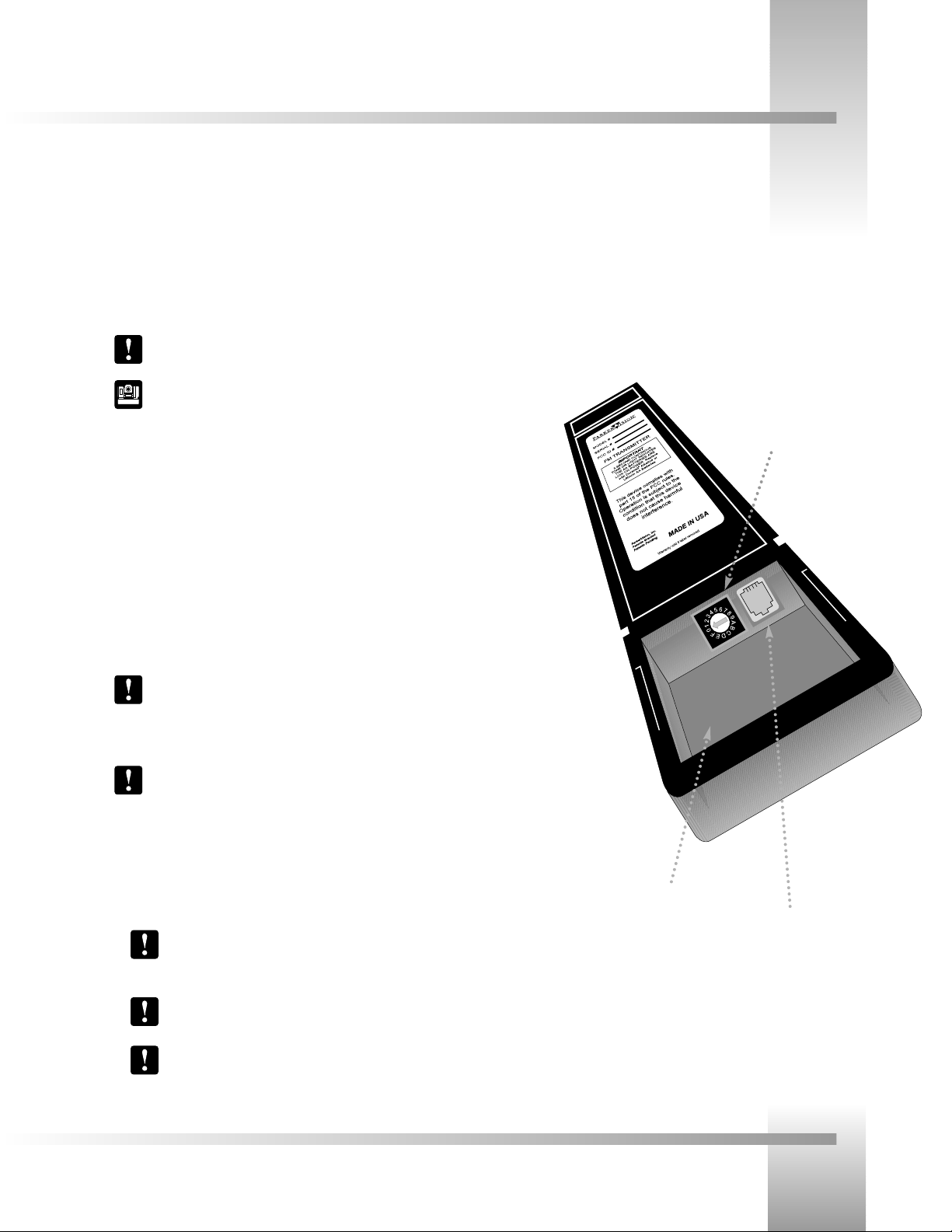
Connecting Your Keypad
1. Adjust the KEYPAD ADDRESS rotary switch (located in the battery compartment of the
keypad) so the selected setting corresponds to the setting of the BASE UNIT ADDRESS
switch on the back of the Camera.
For multiple-camera applications, refer to page 6.
For information on how to set the Base Unit Address on your CameraMan
camera, refer to the 3-CCD CameraMan’s Installation and Operations
Manual.
2. Configure the keypad for your application:
For Wireless RF Mode (up to 60’/18.28m):
• Install the supplied AA batteries in the Camera Control Keypad by removing the
battery door and inserting the batteries into the battery compartment.
• Replace the battery door.
• Press one of the PAN/TILT arrows on the keypad and verify that the LED on the
front of the keypad illuminates. This indicates that the batteries are installed properly.
If the light does not illuminate, then the batteries may be installed backwards.
Reverse the batteries and try again. If you install a low battery, the keypad emits
a long beep.
If the batteries are inserted improperly, it will not damage the keypad. The
keypad will simply not work.
For Hard-wired Mode (up to 250’/76.2m):
• Connect the CameraMan Keypad Cable to the RJ-11 type jack located in the battery
compartment of the Keypad.
• Connect the other end of the cable to the PVI Com port on the CameraMan camera.
When the system is powered on, the light on the keypad should illuminate
momentarily, indicating the keypad is ready for operation. The light located
above the PVI COM port on the camera indicates communication activity.
You do not need batteries installed in the Camera Control Keypad when
using it in hard-wired mode.
Using cable other than ParkerVision-supplied cable for the PVI COM port
may cause damage.
Your Camera Control Keypad can be used in either a wireless or hard-wired mode. The wireless mode enables you to move freely
around the room, while the hard-wired option enables you to control the camera from greater distances. For either mode, follow the
steps below to connect your keypad to your camera system.
RJ-11 jack, for hard-wired mode
Battery compartment
Keypad Address
Page 7

Page 4
CameraMan®3-CCD Camera Control Keypad Operations Manual
Orienting the Pan Arrows
You can configure the Camera Control Keypad to pan left and right according to your specific application needs. The following
explains how to understand, configure, and control the camera’s panning motion.
Example 2: Facing away from the camera.
Your line of sight
Example 1 (Default setting): Facing toward the camera.
Your line of sight
Understanding The Panning Motion
The examples on the right explain when you might want to re-configure the pan arrows on
your Camera Control Keypad.
The default setting, shown in Example 1, is designed to operate as if you are facing the
CameraMan camera. Some examples of applications that would benefit from the default
settings are:
• Distance Learning where you are the instructor.
• Presentations where you are the presenter and the audience members are watching
you on a monitor.
• Videoconferences where the you are an on-screen participant.
• Any other application where you, the camera controller, need to be on camera.
There are applications, however, in which you are not facing the camera (example 2), so the
default setting will not work. These applications require that you re-orient the PAN arrows (see
below). Some examples of applications that might benefit from this re-orientation are:
• Presentations where you are not the presenter, but are controlling the camera’s
movement.
• Videoconferences where you are a moderator, but not an on-screen participant.
• Applications where you are controlling the camera from a control room.
• Any other application where you, the camera controller, do not need to be on
camera.
Re-Orienting The Pan Arrows
To re-orient (reverse) the setting of the pan arrows on your Camera Control Keypad, use the
following procedure:
1. Select the camera you wish to re-orient (see page 6).
2. Press and hold ENTER and autoIMAGE simultaneously.
3. Listen for a beep, indicating that the reversal is complete.
4. Release the buttons.
5. Verify that the orientation has changed.
Page 8

Page 5
Congure Your 3-CCD Camera Control Keypad
Maximum Pan and Tilt Configuration
Now that you’ve learned how to program the pan arrows to meet your application’s needs, you can customize further how your
Camera Control Keypad works with your CameraMan system.
180° Default PAN Settings
50° Default TILT Settings
359° Maximum Pan Settings
Maximum Pan/Tilt Travel
Once the CameraMan Camera is installed, you can configure the PAN/TILT settings to suit
your application. The CameraMan camera has a maximum PAN range of 359°, but comes
programmed with factory default settings for maximum PAN/TILT settings of ±90° of PAN
and ±25° of TILT. You can do the following to change the maximum position settings:
1. Select the camera you wish to adjust (see page 6).
2. Press and hold ENTER.
3. While holding ENTER, use the PAN/TILT arrows to move the camera to the
maximum desired position in a given direction.
4. Release ENTER to set the maximum desired position for that direction.
5. Listen for two beeps to indicate that the maximum position for that direction
has been set.
6. If desired, repeat steps 2-5 to set all maximum positions (left, right, up, and down).
7. If desired, repeat steps 1-6 for additional cameras.
Page 9

Page 6
CameraMan®3-CCD Camera Control Keypad Operations Manual
Multiple Camera Applications
Multi-Camera Control (wireless)
In this mode, the keypad communicates with each camera using RF (wireless) communications.
1. Make sure your cameras are all within 60 feet/18.28 meters of the keypad.
See your 3-CCD CameraMan Installation and Operations Manual for more
information on daisy-chaining your cameras.
2. Set the KEYPAD ADDRESS on your Camera Control Keypad to match the BASE
UNIT ADDRESS on the first camera.
See page 3 for more information on setting the KEYPAD ADDRESS.
3. Set the BASE UNIT ADDRESS on the second and third cameras to follow successively
the address you used for the first camera.
Camera Base Unit Address Keypad Address
100
21
32
4. Set the RF Command configuration switch on cameras 2 and 3 to ENABLE (UP).
See your 3-CCD CameraMan Installation and Operations Manual for more
information on setting the configuration switches.
Back of Camera Control Keypad
Camera 1
Camera 2
Camera 3
Camera Select buttons
1, 2, and 3
Your Camera Control Keypad can control the pan/tilt, zoom, FOCUS, and IMAGE for up to three separate cameras. Multiple
CameraMan cameras can be controlled in one of three ways: wireless, hard-wired, or a combination of the two. Follow the steps
below to enable the keypad to work properly with multiple cameras.
Multi-Camera Keypad Usage
To control any of the three cameras in your multi-camera network, push one of the CAMERA
SELECT buttons marked 1, 2, and 3 at the top of your keypad. The button marked 1
corresponds to Camera One, the button marked 2 corresponds to Camera Two, and the
button marked 3 corresponds to Camera Three.
All camera control and Location Preset commands are issued to the last camera
selected.
Page 10

Page 7
Congure Your 3-CCD Camera Control Keypad
Multiple Camera Applications
Multi-Camera Control (hard-wired)
In this mode, the keypad communicates with camera one using the hard-wired connection. Any
commands sent to cameras two or three will be received by camera one and sent to the
proper camera using RS-485 communications.
1. Make sure your cameras are daisy-chained together.
See your 3-CCD CameraMan Installation and Operations Manual for more
information on daisy-chaining your cameras.
2. Set the KEYPAD ADDRESS on your Camera Control Keypad to match the BASE
UNIT ADDRESS on the first camera.
See page 3 for more information on setting the KEYPAD ADDRESS.
3. Set the BASE UNIT ADDRESS on the second and third cameras to follow successively
the address you used for the first camera.
Camera Base Unit Address Keypad Address
100
21
32
4. Set the RF Command configuration switch on cameras 1, 2, and 3 to DISABLE (UP).
See your 3-CCD CameraMan Installation and Operations Manual for more
information on setting the configuration switches.
5. Connect the Keypad to the PVI COM port on Camera One using the CameraMan
Keypad Cable (hard-wired mode only).
Back of Camera Control Keypad
Camera 1
Camera 2
Camera 3
Page 11

Page 8
CameraMan®3-CCD Camera Control Keypad Operations Manual
Multiple Camera Applications
Multi-Camera Control (wireless and wired combined)
In this mode, the keypad will communicate with camera one using RF (wireless). Any
commands sent to cameras two or three will be received by camera one and sent to the
proper camera using RS-485 communications.
1. Make sure camera one is within 60’/18.28m of the keypad.
2. Make sure cameras two and three are daisy-chained together.
See your 3-CCD CameraMan Installation and Operations Manual for more
information on daisy-chaining your cameras.
3. Set the KEYPAD ADDRESS on your Camera Control Keypad to match the BASE
UNIT ADDRESS on the first camera.
See page 3 for more information on setting the KEYPAD ADDRESS.
4. Set the BASE UNIT ADDRESS on the second and third cameras to follow successively
the address you used for the first camera.
Camera Base Unit Address Keypad Address
100
21
32
5. Set the RF Command configuration switch on cameras 2 and 3 to DISABLE (UP).
See your 3-CCD CameraMan Installation and Operations Manual for more
information on setting the configuration switches.
Back of Camera Control Keypad
Camera 1
Camera 2
Camera 3
Page 12

Page 9
Use Your 3-CCD Camera Control Keypad
Operating Your Camera Control Keypad
Now that you’ve learned what the buttons are for and configured them to work properly, it’s time to put them to use. Here is the
basic functionality of each button.
Controlling The Camera and Image
Manual Pan/Tilt Arrows
Press the up, down, left, and right PAN/TILT arrows to pan or tilt the camera according to
your setup (see page 4).
Zoom Perspective Buttons
• Press the Zoom IN button for the camera to zoom in for a tighter view.
• Press the Zoom OUT button for the camera to zoom out for a wider view.
The Zoom can be adjusted manually and stored in a Location Preset.
IMAGE Setting Buttons
Manual
• Press and release the top IMAGE button to brighten the picture.
• Press and release the bottom IMAGE button to darken the picture.
The IMAGE setting can be adjusted manually and stored in a Location Preset.
You may want to use the Manual IMAGE setting when you are not fully satisfied
that the video image is as dark or light as you want. Otherwise, the IMAGE setting
adjusts itself automatically to the lighting conditions in all areas of the room.
autoIMAGE
In this mode, CameraMan adjusts the IMAGE (light & dark) automatically for each camera
view. Press and release both the top and bottom IMAGE buttons to enable automatic
operation of the CameraMan’s IMAGE function.
An autoIMAGE setting can be stored in a Location Preset.
FOCUS Setting Buttons
• Press the UP arrow button to focus far (send the focal point farther from the camera).
• Press the DOWN arrow button to focus near (bring the focal point closer to the camera).
Page 13

Page 10
CameraMan®3-CCD Camera Control Keypad Operations Manual
Operating Your Camera Control Keypad
The Camera Setup Mode buttons (with green text) on your keypad enable you to adjust the camera’s settings through four onscreen menus. These adjustments should be made by qualified technical personnel only.
If you are using a CameraMan SHOT Director with your camera(s), you should
perform all setup through the SHOT Director. Do not use these keypad features.
Adjusting the Camera Setup Mode Settings
Setup and Mode Buttons
To enter the camera setup mode:
• Press and hold SETUP and MODE simultaneously for 2.5 seconds.
The keypad should beep once.
• Release both buttons.
• The video flashes and an on-screen menu appears when it enters the camera setup mode.
MENU EDIT Arrows
To select a setting, or the value of a setting, use the PAN/TILT MENU EDIT buttons (left/right
and up/down) on your keypad:
• TILT UP: moves the on-screen cursor up.
• TILT DOWN: moves the on-screen cursor down.
• PAN RIGHT: increases, or changes the setting.
• PAN LEFT: decreases, or changes the setting.
To change between the various on-screen settings menus:
• Place the cursor on the first line of the menu using the menu edit UP and DOWN arrows.
• Select the menu page (1-4) using the menu edit LEFT and RIGHT arrows.
For more information on the on-screen camera settings and their functionality, refer to
the 3-CCD CameraMan Installation and Operations Manual.
When accessing the on-screen camera settings, do not change the BAUD RATE. This
may impact the camera’s communication links.
MENU Button
Press the Menu button to toggle between the on-screen settings menu and the video image.
BARS Button
Press the Bars button to toggle between the on-screen color bars and the video image.
White Balance Button
Press the button next to the W to set the white balance automatically when the on-screen
menu is turned off.
Once all adjustments have been made, the camera must be returned to system mode for
normal operation. Just follow the same directions as above to enter camera setup mode. The
menu disappears and the camera returns to normal operation.
MENU button
MENU EDIT arrows
SETUP button MODE button
BARS button
WHITE BALANCE button
Page 14

Page 11
Use Your 3-CCD Camera Control Keypad
Location Presets
Working With Location Presets
What are Location Presets?
Location Presets are stored locations that can be recalled using the Camera Control Keypad.
Each Location Preset memorizes and stores the following camera control functions:
• PAN/TILT position
• ZOOM perspective
• IMAGE setting
• FOCUS setting
To Set or Change a Location Preset
1. Select the camera you want to program using the CAMERA SELECT buttons.
(If only using one camera, press CAMERA SELECT 1).
2. Use the PAN/TILT arrows to move the camera to the desired location.
3. If desired, use the manual ZOOM buttons to set the needed Zoom perspective.
4. If desired, use the manual IMAGE buttons to set the needed light/dark contrast.
5. If desired, use the FOCUS buttons to change the camera’s focal point.
6. Input the Location Preset number (1–125).
7. Press and hold ENTER until you hear two beeps. The two beeps indicate the Location
Preset has been stored.
To Recall a Location Preset
1. Select the camera of choice (if only using one camera, press CAMERA SELECT 1).
2. Input the Location Preset number (1–125).
3. Press and release ENTER.
The CameraMan camera moves to the memorized location and recalls the information
stored for that Location Preset.
To move quickly from shot to shot using the Camera Control Keypad, use the Location Preset function on the keypad. With Location
Presets, you can store and recall up to 125 predetermined locations.
Step 1
Step 2
Step 3
Step 4
Step 5
Step 6
Step 7
Page 15

Page 12
CameraMan®3-CCD Camera Control Keypad Operations Manual
Appendix A : Troubleshooting and Specications
If you have any problems with your Camera Control Keypad, please refer to the following Troubleshooting section. If you still have
questions or problems, please contact your authorized ParkerVision reseller or contact ParkerVision Product Support at 904-737-
1367.
Troubleshooting
Problem: The Camera Control Keypad will not control the CameraMan
Camera when used in the wireless RF mode.
Solution: 1. Verify that the battery is installed in the keypad properly (see page 3).
2. Verify that the BASE UNIT ADDRESS switch on the back of the
CameraMan Camera, and the BASE UNIT ADDRESS switch in
the battery compartment of the keypad are set to the same setting (see page 3).
3. Verify that the RF command switch on the back of the
CameraMan camera is set to ENABLE (see your 3-CCD
CameraMan Installation and Operations Manual).
4. Verify that the light on the front of the Camera Control Keypad
illuminates for a few seconds when the battery is first plugged in.
5. Be sure that you have pressed the appropriate CAMERA SELECT
button on the Camera Control Keypad corresponding to the camera you wish to control (see page 6). If only using one camera,
press CAMERA SELECT 1.
Problem: The Camera Control Keypad will not communicate with the
CameraMan Camera in the "hard-wired" mode.
Solution: 1. Verify that the CameraMan Keypad Cable is connected from the
PVI COM port on the back of the camera to the RJ-11 jack in the
battery compartment of the Camera Control Keypad (see page 3).
2. Verify that the BASE UNIT ADDRESS switch on the back of the
CameraMan camera and the BASE UNIT ADDRESS switch in
the battery compartment of the keypad match (see page 3).
3. Does the light on the front of the keypad come on for a few seconds when the keypad is first plugged in? If not, replace cable
only with a ParkerVision-supplied cable.
4. Be sure that you have pressed the appropriate CAMERA SELECT
button on the Camera Control Keypad corresponding to the camera you wish to control (see page 6). If only using one camera,
press CAMERA SELECT 1.
Specifications
Wireless Mode:
RF Range: . . . . . . . . . . . . .60’/18.28m from Camera (typical)
Power: . . . . . . . . . . . . . . .(2) AA DURACELL® Battery
Hard-Wired Mode:
Range: . . . . . . . . . . . . . . .250’/76.2m from Camera (typical)
Power: . . . . . . . . . . . . . . .Supplied through Cable
Keypad Dimensions: . . . . .US: 7.0"L x 2.20"W x 0.85"H
INT: 17.78cm L x 5.59cm W x 2.16cm H
Return To Default
The Return to Default command resets the cameras
maximum pan/tilt position and orientation to the factory
settings and clears location presets 1, 2, and 3 (presets 4125 will not change). Please use with caution.
Returning to the Factory Defaults:
1. Simultaneously press the IMAGE
light and number 3 button for
approximately one second.
2. Release the buttons.
3. If it was off-center, the camera returns to the home position.
Page 16

Page 13
Appendices
Notes
Page 17

 Loading...