

Page 1

RCP-BR Panel
Guide to Installation and Operation
M885-9900-100
September 2009
Miranda Technologies Inc.
3499 Douglas-B.-Floreani
St-Laurent, Québec, Canada H4S 1Y6
Tel. 514-333-1772
Fax. 514-333-9828
www.miranda.com
© 2009 Miranda Technologies Inc.
Page 2

Copyright © 2009 Miranda Technologies Ltd. All rights are reserved and, under
the copyright laws, this manual may not be reproduced in any form, in whole or in
part, without the prior written consent of Miranda Technologies Ltd.
Windows95, Windows98, Windows2000, WindowsNT and
WindowsXP are registered products of Microsoft Inc.
Page 3

RCP-BR: Guide to Installation and Operation
Compliance Information
Electromagnetic Compatibility
This equipment has been tested and found to comply with the limits for a Class A
digital device, pursuant to Part 15 of the FCC Rules. These limits are designed to
provide reasonable protection against harmful interference when the equipment is
operated in a commercial environment. This equipment generates, uses, and can
radiate radio frequency energy and, if not installed and used in accordance with
the instruction manual, may cause harmful interference to radio communications.
Operation of this equipment in a residential area is likely to cause harmful
interference in which case the user will be required to correct the interference at
their own expense.
This equipment complies with the requirements of the following standards:
EN 55022, Radiated Emissions, Class A
EN 55022 Conducted Emissions, Class A
EN 61000-4-2, -3, -6, -11, Electromagnetic Immunity
EN 61000-3-2 & -3-3, Electromagnetic Disturbance.
Miranda Technologies Inc.
Page 4

RCP-BR: Guide to Installation and Operation
How to contact us:
For technical assistance, please contact the Miranda technical support centre
nearest you.
Americas
Telephone:
+1-800-224-7882
e-mail:
techsupp@miranda.com
Europe, Middle East, Africa, UK
Telephone:
+44 (0) 1491 820222
e-mail:
eurotech@miranda.com
France (only)
Telephone:
+33 (0) 1 55 86 87 88
e-mail:
eurotech@miranda.com
Visit out web site at www.miranda.com
Asia
Telephone:
+852-2539-6987
e-mail:
asiatech@miranda.com
China
Telephone:
+86-10-5873-1814
e-mail:
asiatech@miranda.com
Miranda Technologies Inc.
Page 5

RCP-BR: Guide to Installation and Operation
Table of contents
1 RCP-BR Panel ........................................................................ 1
1.1 Introduction................................................................................. 1
1.2 Features ..................................................................................... 1
2 Setting up of the RCP-BR panel............................................ 2
2.1 Connecting up the panel ............................................................ 2
2.2 Network configuration................................................................. 3
2.3 Station configuration................................................................... 7
2.3.1 Installing Xpanel configuration tool on a PC ................. 8
2.3.2 Defining the RCPs to be configured ............................ 11
2.3.3 Setting up the station configuration ............................. 14
3 Using the RCP-BR panel...................................................... 20
3.1 Turning on the unit ................................................................... 20
3.2 Turning off the unit ................................................................... 20
3.3 Panel basics ............................................................................. 22
3.3.1 Panel Lock button........................................................ 23
3.3.2 Channel Select ............................................................ 23
3.3.3 DSK Off ....................................................................... 23
3.3.4 Take............................................................................. 23
3.4 Selecting a channel .................................................................. 24
3.4.1 Channel ganging ......................................................... 24
3.4.2 User channels ............................................................. 26
3.5 The Main panel......................................................................... 28
3.5.1 Cutting a keyer up or down ......................................... 30
3.5.2 Setting fade rates ........................................................ 31
3.5.3 Cutting a voice-over up or down.................................. 32
3.5.4 Macros......................................................................... 33
3.5.5 Fade to black / silence................................................. 34
3.5.6 Arming multiple events on a Take ............................... 34
3.6 Loading media into a keyer ...................................................... 35
3.6.1 Filter............................................................................. 38
Miranda Technologies Inc.
Page 6

RCP-BR: Guide to Installation and Operation
3.7 Modifying media in a keyer .......................................................40
3.7.1 Adjusting media position ..............................................40
3.7.2 Adjusting the media cropping ......................................41
3.7.3 Adjusting the media clip, gain and transparency .........42
3.8 Audio.........................................................................................43
3.8 Voice-overs ...............................................................................45
3.9 The System panel .....................................................................47
3.10 Alarms.......................................................................................49
4 The web interface .................................................................50
4.1 Maintenance .............................................................................52
4.1.1 Update .........................................................................53
4.1.2 Update history..............................................................54
4.1.3 Install panels ................................................................55
4.1.4 System restart..............................................................56
4.1.5 System shutdown.........................................................57
4.2 Diagnostics ...............................................................................58
4.2.1 Retrieve log files ..........................................................59
4.2.2 Watch log .....................................................................61
4.2.3 Running processes ......................................................62
4.3 Setup.........................................................................................63
4.3.1 Network setup ..............................................................64
4.3.2 Set hostname...............................................................65
4.3.3 Time setup ...................................................................66
4.3.4 Mouse setup ................................................................67
4.3.5 Serial number...............................................................68
5 Installation.............................................................................69
5.1 Mounting ...................................................................................69
5.1.1 Mounting with ears.......................................................69
5.1.2 Mounting with 30 degree brackets...............................71
5.1.3 With 60 degree Desk-Mounting kit, RCP-BR-DM-KIT .72
5.1.4 With Rack-Mounting kit, RCP-BR-RM-KIT ..................73
5.2 Ventilation .................................................................................74
Miranda Technologies Inc.
Page 7

RCP-BR: Guide to Installation and Operation
Power requirements ................................................................. 74
5.3
5.4 RCP-BR rear connections ........................................................ 75
5.4.1 Summary ..................................................................... 75
5.4.2 DC power connector pinout (8 pin DIN, female) ......... 76
5.4.3 GPIO pinout (15-way D-type) ...................................... 77
5.5 Mechanical ............................................................................... 78
5.6 Environment ............................................................................. 78
5.6.1 Operating..................................................................... 78
5.6.2 Storage ........................................................................ 78
5.7 Other......................................................................................... 79
5.7.1 RTC battery ................................................................. 79
5.7.2 Compact Flash ............................................................ 79
Miranda Technologies Inc.
Page 8

Page 9

RCP-BR: Guide to Installation and Operation
1 RCP-BR Panel
1.1 Introduction
The highly graphical, touch screen Branding Panel provides highly informative
and easy control of Miranda’s channel branding processors, including the
Intuition XG, the Imagestore 750, and the Densite LGK-3901 / DSK-3901.
1.2 Features
FLEXIBLE AND USER-FRIENDLY CONTROL PANEL
• Rich graphical interface
• Customizable layouts via standalone software running on a PC
• Combination of touch screen and button control
• Intuitive operation
• Full tallies from devices under control
COMPLETE CONTROL FOR BRANDING APPLICATIONS
• Full keyer and voice-over control
• Media browsing with graphical thumbnails
• Quick adjustment of parameters via rotaries
• Custom branding macro recall
• Easy configuration of keyers and voice-overs
OPTIMIZED FOR MULTI-CHANNEL ENVIRONNMENTS
• Channel ganging capable (simultaneous multi-channel control)
• Easy to use channel selector
ELEGANT DESIGN AND SIMPLE CONNECTIVITY
• 1/2 rack / 3RU form factor
• Desk or turret mount
• Connects to branding devices via Ethernet (Oxtel protocol)
• Two USB ports for software upgrades or mouse/keyboard
Miranda Technologies Inc. Page 1
Page 10
RCP-BR: Guide to Installation and Operation
2 Setting up of the RCP-BR panel
Before using the RCP-BR panel to control a system, two things will need to be
setup, these are:
1. The networking configuration.
2. The station configuration which defines which devices the panel will
control and the configuration of these devices into channels.
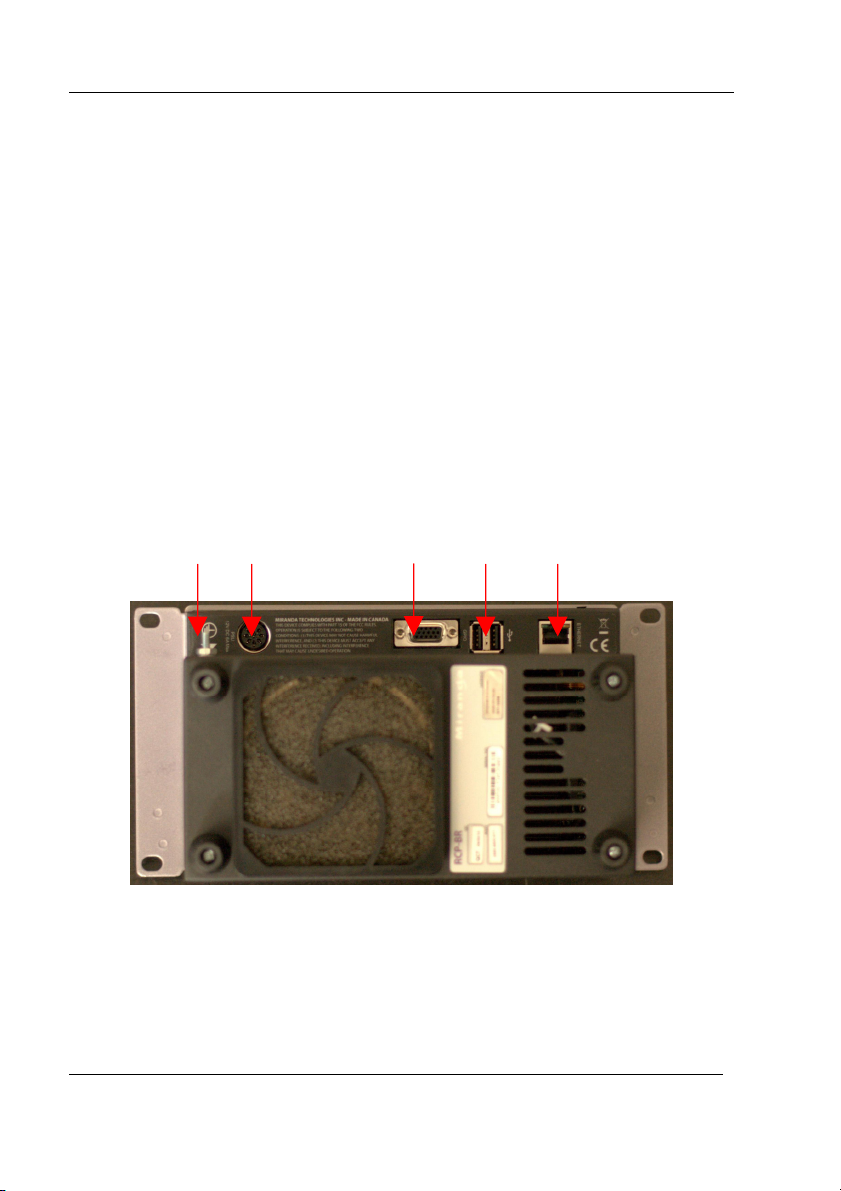
2.1 Connecting up the panel
Please refer to figure 2-1 for a picture of the rear of the RCP-BR panel. For
normal usage an Ethernet cable must be inserted with a connection to the network
that the devices to be controlled are on. In addition there is an earth stud for
earthing the unit.
Earth stud DC Power GPI USB Ethernet
Figure 2-1 Main Rear connections for the RCP-BR panel
To power up the unit connect the remote power adapter to the power socket on the
RCP-BR panel before the power adapter is connected to the mains supply.
Page 2 Miranda Technologies Inc.
Page 11
RCP-BR: Guide to Installation and Operation
2.2 Network configuration
The RCP-BR panel comes pre-configured to use DHCP to automatically
configure its networking. If a static IP address is required for the unit then a USB
keyboard and mouse should be added to the unit. The unit should be powered up.
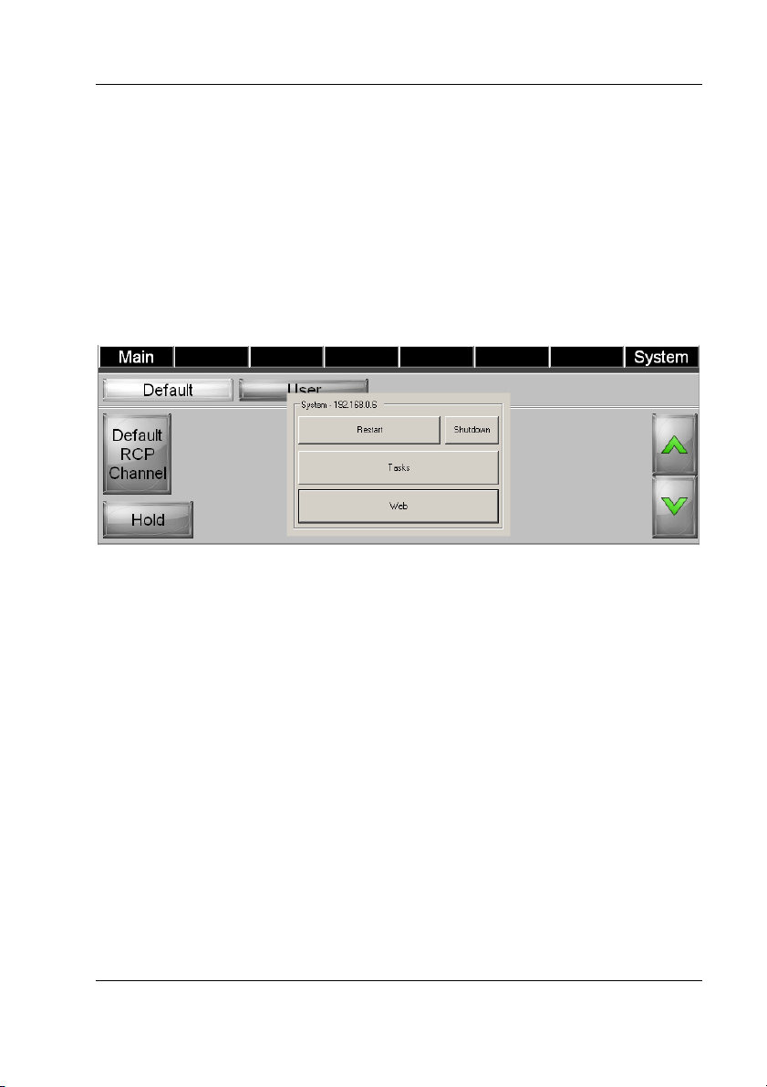
Once the unit has started up and the channel selector dialogue is displayed the
ALT + Tab keys should be pressed on the keyboard, this will display the dialogue
as shown in figure 2-2. On the touchscreen press the button marked as Web.
This will display the web log-in screen as shown in figure 2-3.
Figure 2-2 Dialogue to select web interface
Miranda Technologies Inc. Page 3
Page 12
RCP-BR: Guide to Installation and Operation
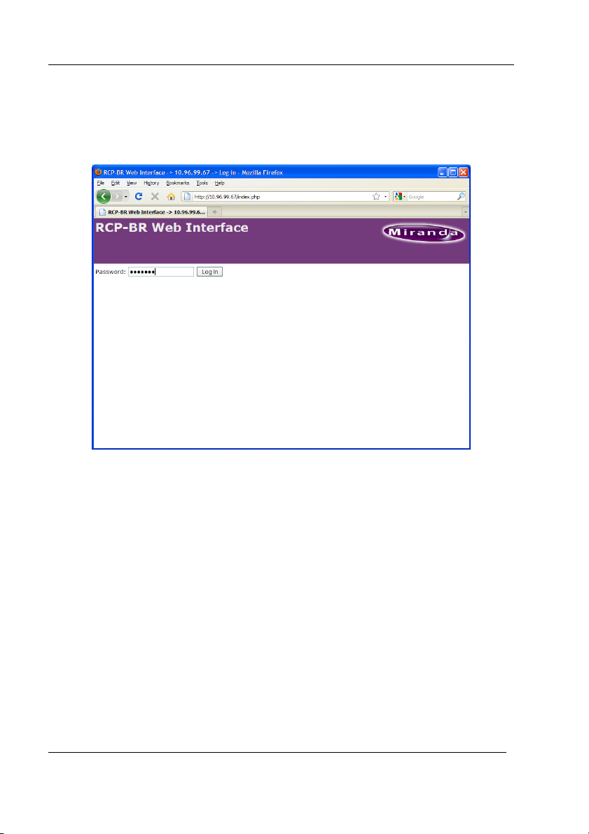
To log-in to the web interface select the area for the password to be typed in by
pressing the screen in this area and then on the keyboard type in the password
miranda (all in lower case). This will then display the main Web Interface screen.
Figure 2-3 RCP-BR Web interface log-in
Page 4 Miranda Technologies Inc.
Page 13
RCP-BR: Guide to Installation and Operation
The first thing to do will be to enable the display of the mouse pointer, to do this,
use the touchscreen to press on the Setup option and then select Mouse setup.
This will display the dialogue shown in figure 2-4. Now press on the ‘Show’
button to display the mouse pointer.
Figure 2-4 Turning on the display of the mouse pointer
Miranda Technologies Inc. Page 5
Page 14

RCP-BR: Guide to Installation and Operation
Having selected to display the mouse pointer now select the Setup option and then
the Network setup option. This will show the network setup dialogue as shown in
figure 2-5. In this dialogue the DHCP setting can be changed to Static and the
static IP address can be entered. Once this has been changed then select the
‘Apply’ button.
Figure 2-5 Setting up a static IP address
The networking on the unit is now configured and the unit should be shutdown.
To do this, close the web browser so that the interface shown in figure 2-2 is
displayed. In this dialogue press the Shutdown button to start the shutdown
process. The unit MUST be left powered on until all the LEDs on the front panel
of the unit have been turned off. At this point the keyboard and the mouse can be
removed from the unit and it can be connected to the system network and the unit
can be repowered.
Page 6 Miranda Technologies Inc.
Page 15

RCP-BR: Guide to Installation and Operation
2.3 Station configuration
Before starting to use the RCP-BR panel the station configuration for the unit
must be setup. The station configuration defines those devices on the network
which the panel should control; these devices could be any of the following:
• Imagestore 300
• Imagestore HD
• Imagestore 750
• LGK-3901
• DSK-3901
• Intuition
• Intuition+
• Intuition XG ( supported in future )
These devices then need to be assigned to a channel. A channel can consist of one
of the following combinations:
1. One ImageStore, LGK-3901 or DSK-3901
2. One Intuition, Intuition+ or Intuition XG
3. One ImageStore, LGK-3901 or DSK-3901 with one Intuition, Intuition+
or Intuition XG
For information on other Miranda devices not in this list please contact Miranda.
The RCP-BR continually monitors all channels in its station configuration for
device status. Increasing the number of channels can slow down RCP-BR
operation. Miranda recommends a maximum of 20 channels / 30 devices.
Note: To ensure correct operation of the RCP-BR panel appropriate software
versions need to be installed on all controlled devices. The minimum
recommended versions are:
Imagestore 300, Imagestore HD, Intuition, Intuition+ 1.13.8.1
Imagestore 750 2.0.2 or 3.1
LGK-3901, DSK-3901 2.1.3 or 3.0
Miranda Technologies Inc. Page 7
Page 16
RCP-BR: Guide to Installation and Operation
2.3.1 Installing Xpanel configuration tool on a PC
In order to setup the station configuration, the Xpanel application must be
installed on to a standard desktop PC or laptop that has network access to the
RCP-BR panel. The Xpanel installer will be found on the ‘User Documentation
and Software’ CD that accompanies the RCP-BR panel. Install the Xpanel
application and then on completion of the installer, run the application. This will
then come up with a dialogue as shown in figure 2-6.
Figure 2-6 Initial dialogue to licence application
To run the Xpanel application the software must be licensed to run on the PC. To
do this when the dialogue shown in figure 2-6 is displayed select the ‘Enter
License’ option. This will then display the ‘License Manager’ dialogue as shown
in figure 2-7.
Page 8 Miranda Technologies Inc.
Page 17
RCP-BR: Guide to Installation and Operation
Figure 2-7 License Manager dialogue
To get the license key for the PC, copy the Customer ID and email this to
support@miranda.com requesting an Xpanel2RCP license. When the license key
is received back this should be pasted into the area of the window directly below
the label ‘License Keys’. Having pasted in the license key the ‘Validate’ button
must be pressed to validate the license key, this will show the ‘License Key
Details’ part of the dialogue as shown in figure 2-8.
Miranda Technologies Inc. Page 9
Page 18
RCP-BR: Guide to Installation and Operation
Figure 2-8 License Key Details
Assuming that the status of the license key is ok, then press the ‘Apply’ button
followed by the ‘OK’ button. If the status is not ok then please contact Miranda
support. Assuming that the license is correct when the ‘OK’ button is selected,
Xpanel will be launched.
Page 10 Miranda Technologies Inc.
Page 19

RCP-BR: Guide to Installation and Operation
2.3.2 Defining the RCPs to be configured
Having successfully licensed the software the initial Xpanel screen is shown in
figure 2-9.
Figure 2-9 Xpanel start-up screen
The Xpanel RCP configuration tool can configure multiple RCPs so only one
instance of this tool is required to configure all RCP-BR panels.
Having started up Xpanel we will need to define in this tool the RCP-BR panels
that we wish to configure and then connect to the device to enable the
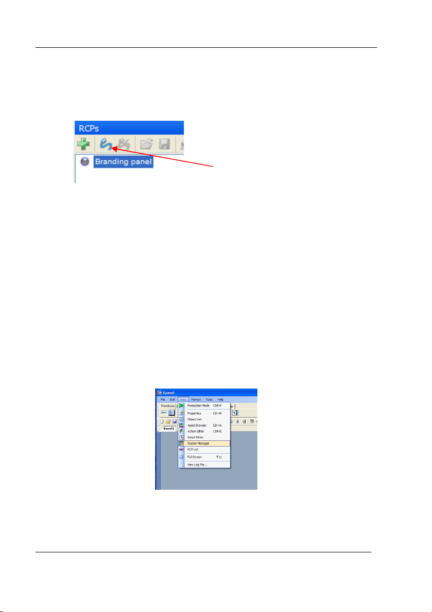
configuration of the panel to be completed. To add the RCP-BR panels the RCP
view must be opened. To do this select the ‘View’ option from the menu and then
select the ‘RCP List’ option as shown in figure 2-10.
Miranda Technologies Inc. Page 11
Page 20

RCP-BR: Guide to Installation and Operation
Figure 2-10 Selection of the RCP List view
When the RCP List option is selected the RCP List View dialogue will be opened
within Xpanel as shown below.
Figure 2-11 Xpanel with the RCP List view open
Page 12 Miranda Technologies Inc.
Page 21
RCP-BR: Guide to Installation and Operation
In this RCP List view we need to define all the RCP-BR panels that we wish to
configure. To do this, select the
icon in the toolbar. This will display the ‘New
RCP’ dialogue as shown in figure 2-12.
Figure 2-12 New RCP setup dialogue
In this dialogue the hostname or the IP address of the RCP-BR panel must be
entered and an optional name for the RCP-BR panel can be entered. If no name is
entered then the IP address or hostname will be shown in the RCP List. Having
completed the definition of the RCP-BR panel select OK and the new entry will
be shown in the RCP List view, as shown in figure 2-13.
Figure 2-13 RCP List view with new RCP-BR panel inserted
Miranda Technologies Inc. Page 13
Page 22
RCP-BR: Guide to Installation and Operation
Co
nnect to an RCP icon
To configure the station configuration on the RCP-BR panel select the RCP-BR
panel in the list to be configured and then select the ‘Connect to an RCP’ icon as
shown in figure 2-14.
Figure 2-14 Connect to an RCP icon
Having selected the ‘Connect to an RCP’ icon, connection will take several
seconds. At the end of which the indicator to the left of the RCP-BR panel will
turn green to indicate that a connection to the device has been successfully
completed. The IP address or hostname of the RCP-BR panel will be displayed
with a red background at the bottom right hand corner of the Xpanel application.
2.3.3 Setting up the station configuration
To setup the station configuration the view for this must be opened. Before
starting to setup the station configuration it is essential that you connect to the
RCP-BR panel to be setup as described in the previous section. To start the setup
of the station configuration select the View option and in the View list select
Station Manager. Please see figure 2-15.
Page 14 Miranda Technologies Inc.
Figure 2-15 Selecting the Station Manager view
Page 23
RCP-BR: Guide to Installation and Operation
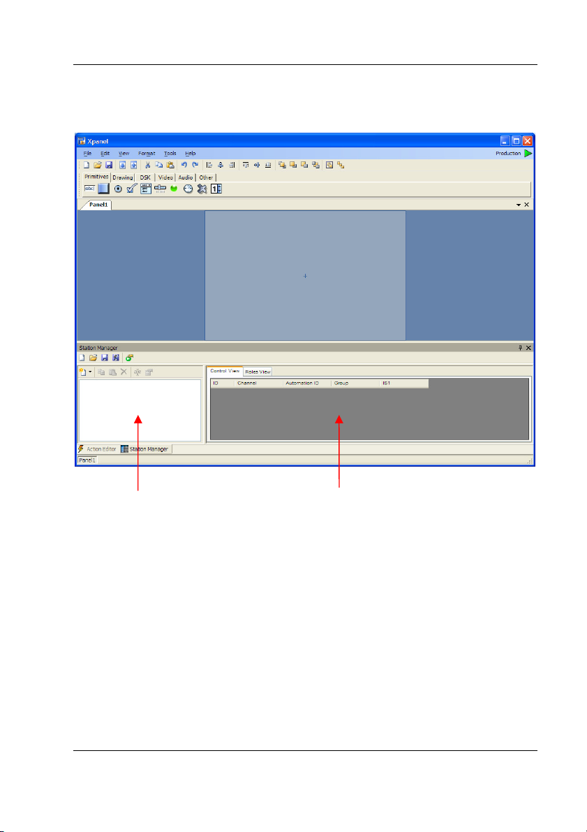
Selecting the Station Manager option will display the following view:
Device area
Channel area
Figure 2-16 Station Manager view
Having opened the view, the first operation to carry out is the definition of the
devices that will be controlled by the RCP-BR panel. These devices are added in
the device area which is on the left of the view. To add a device, select the ‘New
device’ icon on the toolbar at the top of the device area as shown in figure 2-17.
This will drop down a list of the devices supported by Xpanel.
Miranda Technologies Inc. Page 15
Page 24
RCP-BR: Guide to Installation and Operation
New device icon
Figure 2-17 Station Manager device toolbar
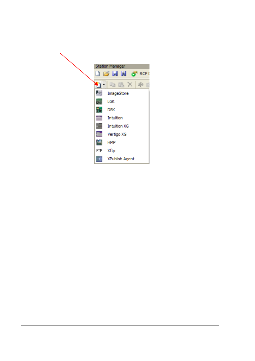
When setting up the station configuration for an RCP-BR panel only the options
ImageStore, LGK, DSK, or Intuition should be selected from this list. Having
selected the appropriate device from this list, the setup dialogue for the device
will be shown. See figure 2-18.
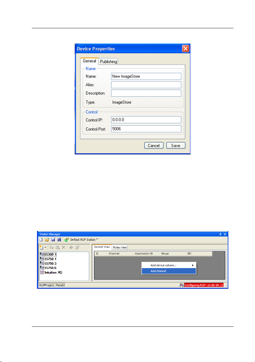
In this dialogue a name can be setup for the device which will make it
distinguishable from other devices that will be added to the configuration. In
addition the IP address of the device must be setup, but the control port should not
be changed. Having made the changes to define the device select the ‘Save’
option. This will close the dialogue and you will now see the new device appear
in the device area of the Station Manager.
Page 16 Miranda Technologies Inc.
Page 25
RCP-BR: Guide to Installation and Operation
Figure 2-18 Configuration for a new device
Having defined all the devices that are to be controlled by the RCP-BR panel it is
then necessary to setup the channels on the device, and for each channel assigned
in the configuration the appropriate devices should be assigned to the channel.
Firstly a new channel should be created in the station configuration. To do this
right click in the channel section of the Station Manager and select the ‘Add
channel’ option as shown in figure 2-19.
Figure 2-19 Adding a channel to the station configuration
Miranda Technologies Inc. Page 17
Page 26
RCP-BR: Guide to Installation and Operation
By default, a channel with one Imagestore will be created (IS1). If you will
require a channel with an Intuition in the configuration then the ‘Add device
column’ option should be selected and the Intuition option should be selected.
The devices from the device area of the station configuration can then be dragged
to the required channel. A + sign will be displayed when the device being
dragged is over a device column in a channel and the device can then be dropped
into the column. An Imagestore, DSK or LGK can only be dropped into an
Imagestore column and an Intuition can only be dropped into an Intuition column.
The device in the device area will then be greyed out to indicate that it is in use by
a channel. A device can only be assigned to one channel, so if it is required by
another channel then it must first be removed from the channel using it. This can
be done by right clicking on the device in the channel.
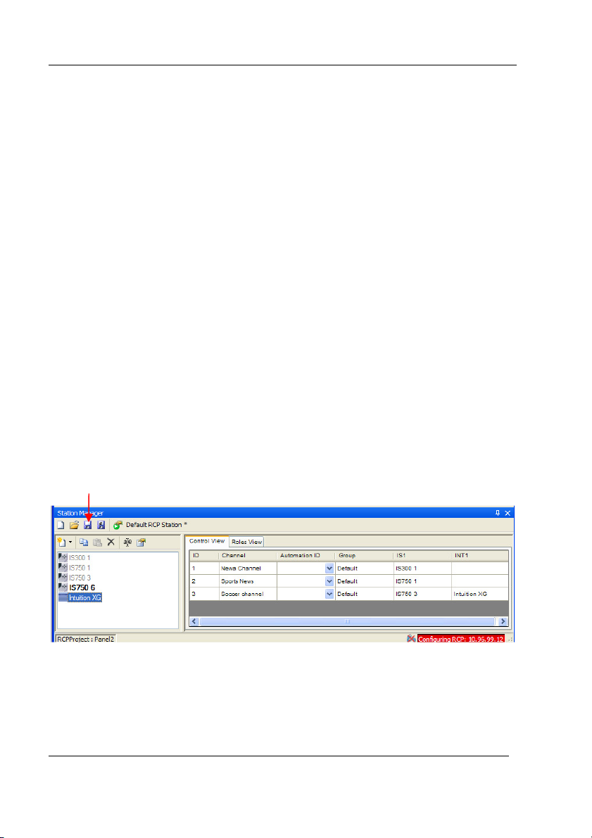
A typical configuration is shown in figure 2-20.
Under the column ‘Group’ you can optionally type in the type of channel that the
new channel is. On the RCP-BR panel if all channels are left as Default all
channels will be shown in one view on the channel selector. This works well if
there are not many channels, but if you want to show groups of channels together
then entering a Group name will separate the channels in the channel selector into
their appropriate groups. An example of Groups is to create three groups - News,
Sport & Default.
Save option
Figure 2-20 Typical setup of station configuration
Page 18 Miranda Technologies Inc.
Page 27

RCP-BR: Guide to Installation and Operation
Having completed the setup of the station configuration the Save option in the top
toolbar should be selected. This will save the station configuration to the RCPBR panel.
Having completed configuration of the RCP-BR panel the connection to the
device in the RCP List view should be dropped. This should be done by selecting
the icon:
in the RCP List view.
The RCP-BR panel should now be ready for use.
Miranda Technologies Inc. Page 19
Page 28

RCP-BR: Guide to Installation and Operation
3 Using the RCP-BR panel
3.1 Turning on the unit
To turn on the unit ensure that the mains supply to the RCP-BR panel power
connector is not connected. Insert the power supply connector into the unit and
then apply mains to the power connector. The LCD on the RCP-BR panel should
initially be off; the LEDs on the bar at the bottom of the unit should gradually
turn on to indicate the progress of the unit’s initialisation. Shortly after the
progress bar has reached the right hand side, the LCD display will turn on
showing the channel selector view.
3.2 Turning off the unit
It is essential that the unit is turned off correctly. To shut down the unit go into
the System panel by selecting the System button on the top bar. This will open
the System panel as shown in figure 3-1.
Figure 3-1 System panel
On the touchscreen press the ‘Shut Down’ button and the panel will change to
display two new buttons – ‘Confirm Shut Down’ and ‘Cancel’. To continue
shutting down the unit press the confirm option. The panels will all close down
and soon after the LCD will turn off, and the bottom bar will show a progress bar
Page 20 Miranda Technologies Inc.
Page 29

RCP-BR: Guide to Installation and Operation
of the LEDs going out. The unit must not be turned off until all the LEDs have
gone out. To power down the unit the mains supply to the RCP-BR panel power
connector must be removed. Do not pull the power connector out of the back of
the unit until the shut down process has completed and the mains has been
removed from the power connector.
Miranda Technologies Inc. Page 21
Page 30

RCP-BR: Guide to Installation and Operation
3.3 Panel basics
The RCP-BR panel provides three input mechanisms for controlling the selected
devices. These are:
1. Physical buttons. These are arranged in three rows with some dedicated
buttons and the remainder which change their functionality during
operation.
2. Rotaries. These are used for setting adjustable values and scrolling the
media browsers. If the rotary is pressed down and rotated the value
being adjusted will change more quickly.
3. Touchscreen. This allows the operator to control some functions within
the panels.
Figure 3-2 shows a panel with key buttons labelled.
Panel lock button Channel select button
Rotary 1
Rotary 3
Rotary 2 Rotary 4
DSK off
Take
Figure 3-2 RCP-BR panel with fixed buttons and rotaries labelled
Page 22 Miranda Technologies Inc.
Page 31

RCP-BR: Guide to Installation and Operation
3.3.1 Panel Lock button
When the Panel Lock button is pressed, the button will light up red and in this
mode all the buttons on the panel and the touchscreen are disabled until this mode
is deselected.
3.3.2 Channel Select
When the RCP-BR panel starts up or when the channel select button is pressed
the channel selection panel is displayed. This panel allows the operator to select a
channel or to gang channels together. This functionality is discussed in detail in
section 3.4.
3.3.3 DSK Off
If a channel is selected then pressing this button will cut all Imagestore and
Intuition keyers down immediately. This will bypass any arm and take setup.
3.3.4 Take
If a channel is selected and a DSK, VO or macro are armed, this button will flash
to indicate that a function is armed. In this situation pressing the Take button will
action all armed events.
Miranda Technologies Inc. Page 23
Page 32

RCP-BR: Guide to Installation and Operation
3.4 Selecting a channel
On start-up or when the CH SEL button is pressed the channel select panel will be
displayed. An example of the panel is shown in figure 3-3.
Figure 3-3 Channel selection panel
The buttons showing Default, Sports and News are groups of channels. This is
set up in the station configuration where channels can be optionally assigned
groups. Selecting the appropriate group button will show only those channels
assigned to the group.
This warning icon which is shown for some channels indicates that there is
a connection error to one of the devices on the channel. As soon as this
connection error is resolved this icon will be automatically removed. A
connection error will be caused by such issues as loss of network communications
to the device, the unit being turned off or restarting.
If there are more than 8 channels in a group the channels can be scrolled up or
down using the scroll up/down buttons at the right hand edge of the panel.
3.4.1 Channel ganging
It is possible to gang two or more channels together. Whenever channels are
ganged any operations carried out on the panel will be sent to all ganged channels.
In this way it is possible to carry out simultaneous actions such as keyer control
Page 24 Miranda Technologies Inc.
Page 33

RCP-BR: Guide to Installation and Operation
on multiple channels simultaneously. To gang channels press the ‘Hold’ button
so that it lights up red. Once this button is selected pressing any subsequent
channel buttons will light these up in addition to those already lit. The first
channel selected is known as the master channel and is lit up red. The importance
of the master channel is that the RCP-BR panel only displays the status of this
channel. Indication such as which media is loaded into a channel or which keyers
are cut up is based on tallies coming back from this device. The channels lit up
white are known as ‘slave’ channels so any action carried out on the RCP-BR
panel will be carried out on these channels but the status of these channels will
not be reflected on the RCP-BR panel.
If you press a slave channel button again the channel will be deselected from the
ganged channels and the button illumination will go out. If the master channel is
pressed then the master channel will be dropped from the ganged group and one
of the slave channels will become the master channel.
Figure 3-4 Channel selector in ganging mode.
To come out of ganging mode press the hold button again so that the illumination
of the button goes out. If channels are already ganged then this will not disable
the ganging but as soon as a new channel is selected, control of all the ganged
channels will be dropped and the newly selected channel will be the only channel
in action.
Miranda Technologies Inc. Page 25
Page 34

RCP-BR: Guide to Installation and Operation
3.4.2 User channels
It is possible for the user to select a subset of ‘user’ channels in the channel
selector which are to be controlled by the operator. To do this press the user
button as shown in figure 3-5.
Figure 3-5 User channel selection
When the ‘User’ button is pressed the user selected channels will be displayed in
the panel. To add new channels to the user list select the ‘Setup’ button. This will
display all the channels from all the groups as shown in figure 3-6.
Figure 3-6 Setup of the user channels
In user channel setup one or many channels can be selected. These channel
buttons will be lit white. It is important to note that this mode has no connection
to channel ganging. The indication of channels in white just indicates that these
channels are being added to the user channel list. When the required channels
Page 26 Miranda Technologies Inc.
Page 35

RCP-BR: Guide to Installation and Operation
have been selected the OK button is pressed and the user channel selection panel
will be shown with these new channels.
Miranda Technologies Inc. Page 27
Page 36

RCP-BR: Guide to Installation and Operation
3.5 The Main panel
To get to the Main panel press on the ‘Main’ button which is always the first
button on the top row of buttons above the LCD.
Figure 3-7 RCP-BR panel showing the Main panel
The main panel gives an overview of the status of the devices being controlled. It
contains thumbnails showing the media and name of the graphic loaded into each
keyer. It shows the setup of the two voice-overs and a monitor of the audio
output if an Imagestore is attached to the channel.
In addition to the overview of the channel status there is another channel selector
on this panel. This channel selector shows all the channels assigned to the ‘user’
channel and will also show any channels which have been selected during the
operation of the RCP-BR panel which are not in the ‘user’ selected channels.
Page 28 Miranda Technologies Inc.
Page 37

RCP-BR: Guide to Installation and Operation
There is also a Hold button to enable channel ganging to be carried out without
having to revert to the channel selector panel again.
Figure 3-8 Main panel
The assignment of keyers shown in this panel will change depending on the
configuration of the panel. The first six positions will always be assigned to
keyers and the second two positions will be assigned to voice-overs. If an
Imagestore, DSK-3901 or LGK-3901 is assigned to a channel this will always
take up the first keyers depending on the number of keyers in the device. If an
Intuition is assigned to a channel and if there is no Imagestore, LGK-3901 or
DSK-3901 the Intuition will take up all six keyer positions. Otherwise the
Intuition will take the remaining keyer positions after the Imagestore keyers.
Similarly the VO information will only be shown if an Imagestore is assigned to a
channel.
If you press the touchscreen in an area with the DSK label or on the image
thumbnail this will move to the media selector panel for the keyer. If the
touchscreen area with the VO label is pressed the VO setup panel will be
displayed. Pressing on the audio meters will display the Audio Setup panel.
Miranda Technologies Inc. Page 29
Page 38

RCP-BR: Guide to Installation and Operation
3.5.1 Cutting a keyer up or down
The RCP-BR panel utilises an arm and take mechanism for cutting keyers up or
down. This means that multiple events can be triggered simultaneously. To arm
a keyer press the keyer button on the middle button bar. The current arm state for
the keyer is indicated in the LCD region directly above the keyer button. See
figure 3-9.
Press these buttons to arm
the appropriate keyer.
Figure 3-9 Keyer buttons with arm state indication
If the area on the LCD is lit as amber this indicates that the keyer is armed to
either cut or fade up or down. Pressing the keyer button will follow the sequence:
1. Arm cut up/down
2. Arm fade up/down
3. Disarm keyer
Page 30 Miranda Technologies Inc.
Page 39

RCP-BR: Guide to Installation and Operation
The current state of the keyer is indicated by the button. If the button is lit red
then the keyer is currently cut up.
Once the keyer is armed, to carry out the armed action, press the ‘Take’ button
which will be flashing red to indicate that an item is armed.
3.5.2 Setting fade rates
The fade rate for the DSK transition can be set in fields from 0-100. To set the
rate it is necessary to switch to the DSK Setup panel. To get to the DSK Setup
panel the DSK Media panel should be selected first. To open this panel press on
the DSK label above the DSK. Once in the DSK Media panel, the Setup panel
can be selected by pressing the Setup button in the top row. This will open the
panel shown in figure 3-10.
Figure 3-10 DSK Setup panel
To adjust the DSK fade rate adjust the top right hand rotary, turning clockwise
increases the delay and anti-clockwise decreases the delay.
Miranda Technologies Inc. Page 31
Page 40

RCP-BR: Guide to Installation and Operation
3.5.3 Cutting a voice-over up or down
The RCP-BR panel utilises an arm and take mechanism for cutting up or down
voice-overs. To arm a voice-over press one of the VO buttons on the middle
button bar. The current arm state for the keyer is indicated in the LCD region
directly above the voice-over button, see figure 3-11.
Figure 3-11 Voice-over buttons and arm indicator
When the voice-over is armed the LCD indicator area above the button is lit
amber, when the indicator is black this indicates that the voiceover is not armed.
When the button is lit red this indicates that the voice-over is cut up and when the
button is off this indicates that the voice-over is cut down. Having armed a voiceover to cut up or down this will be carried out when the Take button is pressed.
Page 32 Miranda Technologies Inc.
Page 41

RCP-BR: Guide to Installation and Operation
3.5.4 Macros
The RCP-BR panel utilises an arm and take mechanism for initiating the action of
a macro. To arm a macro press one of the macro buttons on the bottom button
bar. The current arm state for the macro is indicated in the LCD region directly
above the macro button, see figure 3-12.
Figure 3-12 Macro buttons and arm indicator
When the indicator area above the macro button is lit amber and the macro button
is lit, this indicates that the macro is armed. When the indicator button is black
and the button is off this indicates that the macro is not armed. Having armed a
macro the macro action is carried on the Imagestore when the Take button is
pressed.
Miranda Technologies Inc. Page 33
Page 42

RCP-BR: Guide to Installation and Operation
3.5.5 Fade to black / silence
Pressing the Fade button to the right of the macro buttons will display the
following panel.
Figure 3-13 Fade to black / silence panel
From this panel all keyers can be faded to black and/or all voice-overs to silence.
The rotaries on the right-hand side can be used to define the fade rates for the
keyer and voice-over fades. A fade rate of zero indicates a cut transition. The
button under the Fade label lights up red whenever keyers are faded to black.
Note: Fading to black / silence is considered to be an emergency measure and as a
result these options are not part of the standard arm and take operation. Selecting
these options will immediately fade the keyers to and from black, and the voiceovers to and from silence.
3.5.6 Arming multiple events on a Take
It is possible to arm any combination of keyers, voice-overs and macros. A
complex transition effect can be created by arming these elements and pressing
the Take button. This means that any arm action on any of these elements will
start simultaneously.
Page 34 Miranda Technologies Inc.
Page 43

RCP-BR: Guide to Installation and Operation
3.6 Loading media into a keyer
To load media into a keyer the media browser panel must be displayed. To do
this press on either the icon showing the media in the keyer or the DSK arm status
label below. This will open the media browser for the appropriate keyer selected.
Press anywhere in this region
to open the browser for DSK 1
Figure 3-14 Indication of what to select to open media browser.
The media browser panel is shown in figure 3-15. When the media browser is
opened, if media is loaded into the keyer, the browser will scroll to display the
current icon for the media selected. The background for the icon is green to
indicate that this is the media loaded into the current keyer.
Note : The media browser keeps itself up-to-date with media on a controlled
device each time a channel is selected: Updating may take a noticeable amount of
time for many pieces of media ( >200 ).
Miranda Technologies Inc. Page 35
Page 44

RCP-BR: Guide to Installation and Operation
Indicator to show
that this media is
loaded into the keyer
Indicator showing which keyer
the media selector is working on
Figure 3-15 Media Browser panel
For most keyers there are three types of media which can be loaded. These are
images, animations and scenes. Alternatively the ‘Ext F&K’ tab allows the
selection of an external fill and key input for the selected keyer.
The exceptions to this are:
• An Intuition which only allows scenes to be loaded and consequently
only shows the Scenes tab.
• An LGK-3901 which only allows media to be loaded into two of its
keyers and for the other three keyers to be assigned to fill and key inputs,
so once media is loaded into two keyers selecting another keyer will only
allow the selection of fill and key inputs.
• A DSK-3901 which only allows fill and key inputs to be associated with
its keyers.
Page 36 Miranda Technologies Inc.
Page 45

RCP-BR: Guide to Installation and Operation
With any of these exceptions only the allowed options will be accessible in the
media browser.
To select an item from the media browser to load into the keyer just press on the
icon on the touchscreen. The background for the icon will initially turn amber to
indicate that the media is loading and then turn green to indicate that the media is
loaded into the keyer. If the background turns red this indicates that the media
failed to load into the keyer.
Rotary control for
scrolling the media
up or down
Figure 3-16 Media browser with control
To scroll the media up or down rotate the top right hand rotary control as shown
in figure 3-16.
To switch between browsing media for images, animations, scenes and external
fill and key press the buttons above the labels at the top of the display.
Miranda Technologies Inc. Page 37
Page 46

RCP-BR: Guide to Installation and Operation
3.6.1 Filter
On devices with a lot of media it is possible to enter a search string so that only
the media containing this string shall be displayed in the browser. To enter the
string press the button above the label marked ‘Filter’. This will display the Filter
panel as shown in figure 3-17.
Figure 3-17 Filter panel
To enter a filter string press the character buttons on the panel. These can only be
selected by pressing the touchscreen. The text entered will be displayed in the top
bar of the Filter panel. Having typed in the search string, press the OK button.
This will close the Filter panel and then initiate a search for media containing the
string typed in. The search string is not case sensitive and will match anywhere in
the media file name.
Pressing Cancel will clear the search string and close the Filter panel. If any
button on the top row of the panel is pressed whilst in the Filter panel this will
have the same effect as pressing the Cancel button. The other buttons on the
panel remain active whilst the Filter panel is displayed.
Page 38 Miranda Technologies Inc.
Page 47

RCP-BR: Guide to Installation and Operation
When a search string is active, it is shown at the bottom of the media browser
panel as shown in figure 3-18.
Current filter string shown here.
Figure 3-18 Media panel showing filter string
Once a filter string has been entered this will be retained if the media browser
changes to browse media of another type. The filter string will also be retained if
another panel is opened. The search string will be retained until another search
string is entered or the string is cleared.
Miranda Technologies Inc. Page 39
Page 48

RCP-BR: Guide to Installation and Operation
3.7 Modifying media in a keyer
The following modifications can be made to media in a keyer:
1. Position.
2. Cropping.
3. Clip, gain and transparency.
To modify the media select the button above the ‘Setup’ label in the media
browser panel. This will open the Setup panel which allows the positioning of
media.
3.7.1 Adjusting media position
The media in a keyer can be repositioned horizontally and vertically. Having
selected the ‘Setup’ option in the Media panel, the panel shown in figure 3-19 will
be displayed.
Figure 3-19 Adjusting media positioning
To adjust the horizontal position of the media in a keyer, rotate the top left rotary
control. This will adjust the horizontal positioning of the media in two pixel steps.
To adjust the vertical position of the media in the keyer, rotate the bottom left
rotary control. This will adjust the vertical positioning of the media in two line
steps.
The position of the media is previewed in the preview screen in the middle of the
panel.
Page 40 Miranda Technologies Inc.
Page 49

RCP-BR: Guide to Installation and Operation
The position adjustment of the media is retained whilst the media is loaded in the
keyer. If the media is reloaded into the keyer this positioning information will be
lost. If it is required to retain the positioning information then the ‘Save Changes’
button must be pressed. This will permanently save the positioning information
with the media so if it is subsequently reloaded into a keyer, the position
information will be reused. Please note that selecting the ‘Save Changes’ button
will also save any changes made to the media cropping or clip, gain and
transparency.
3.7.2 Adjusting the media cropping
To adjust the media cropping select the button above the ‘Crop’ label in the media
Setup panel. This will open the cropping panel as shown in figure 3-20.
Figure 3-20 Adjusting the media cropping
The cropping of the media can be adjusted using all of the rotary controls on the
RCP-BR panel. As the cropping is adjusted using these controls, the extent of the
cropping on the media will be shown in the preview screen in the middle of the
panel. The cropping area will be displayed with a diagonal hatching and the
colour of the media is inverted.
The media cropping in this panel is retained as long as the media is loaded into
the keyer. If the media is reloaded any cropping information will be lost. If the
cropping information is required to be retained when the media is loaded in the
future, the ‘Save Changes’ button must be pressed. Please note that selecting this
Miranda Technologies Inc. Page 41
Page 50

RCP-BR: Guide to Installation and Operation
button will also save any changes made to the media position or clip, gain and
transparency.
3.7.3 Adjusting the media clip, gain and transparency
To adjust the clip, gain and transparency of the media press the button above the
CGT label in either the Setup or Crop panels. Selecting the CGT option will
display the clip, gain and transparency panel as shown in figure 3-21.
Figure 3-21 Adjusting the media clip, gain and transparency
To adjust the clip, gain or transparency turn the appropriate rotary positioned next
to the value to be changed.
Once the clip, gain or transparency has been modified these changes will be
retained as long as the media is loaded into the keyer. If the media is reloaded
into the keyer then these modifications will be lost. To save these changes with
the media press the ‘Save Changes’ button. This will save these changes with the
media. Please note in addition to saving the clip, gain and transparency values
this will also save the positioning and cropping information currently setup for the
media.
Page 42 Miranda Technologies Inc.
Page 51

RCP-BR: Guide to Installation and Operation
3.8 Audio
The Audio panel is displayed when the ‘Audio’ button is pressed or the audio
meters are pressed on the touchscreen in the main panel. This Audio button will
only be available if the device in the channel is an Imagestore. The audio panel is
shown in figure 3-22.
Rotate to
change output
gain.
Figure 3-22 RCP audio output control
To modify the audio output level the top left rotary control can be used to increase
or decrease the gain from -99.5 to +28.0dB. The current audio levels on the
preview and programme outputs of the Imagestore are shown in the audio meters.
Miranda Technologies Inc. Page 43
Page 52

RCP-BR: Guide to Installation and Operation
To adjust the audio input settings press the button above the Input label. This will
display the audio input panel as shown in figure 3-23.
Figure 3-23 Audio input setup
The rotaries are used to adjust the audio input levels for each of the four input
channels. Each of the four input channels can be muted or have its phase changed
by pressing the touchscreen. The audio input shuffle can be adjusted by selecting
the appropriate shuffle settings in the audio shuffle configuration to the right of
the phase buttons.
Page 44 Miranda Technologies Inc.
Page 53

RCP-BR: Guide to Installation and Operation
3.8 Voice-overs
The current voice-over status is shown in the main panel as shown in figure 3-24.
Figure 3-24 Voice-over status indications on main panel
The voice-over graph shows a representation of the preset and duck levels
currently configured for each voice-over. The voice-over label shows the arm
state for the voice-over. If this is amber then the voice-over is armed. The button
is lit to indicate whether the voice-over is active.
To adjust the voice-over settings press the voice-over graph or label on the
touchscreen. This will open the voice-over setup panel as shown in figure 3-25.
Figure 3-25 Voice-over setup panel
Miranda Technologies Inc. Page 45
Page 54

RCP-BR: Guide to Installation and Operation
To adjust the duck and preset levels for the voice-over turn the rotaries on the left
hand side of the panel. To adjust the voice-over rate turn the rotary on the top
right hand side of the RCP-BR panel.
As the duck, preset and rate change, the voice-over graph on the panel will be
automatically updated to reflect the current settings.
The voice-over input shuffle can be adjusted using the voice-over shuffle control.
Page 46 Miranda Technologies Inc.
Page 55

RCP-BR: Guide to Installation and Operation
3.9 The System panel
The System panel displays information regarding the RCP-BR panel. It also
allows for the configuration of the LED brightness, access to alarms and the
mechanism for restarting or shutting down the RCP-BR panel. The System panel
is shown in figure 3-26 and is opened by pressing the button above the System
label at the top right hand of any panel.
Figure 3-26 System panel
If the System label is lit red, it indicates that one of the devices configured on the
RCP-BR panel is alarmed. To find out which device is alarmed press the
‘Alarms’ button within the System panel.
To adjust the LED brightness turn the top right rotary. This will adjust the
brightness of the LEDs, where 1 is the dimmest and 8 the brightest setting.
Miranda Technologies Inc. Page 47
Page 56

RCP-BR: Guide to Installation and Operation
To shut down the unit press the ‘Shut Down’ button. This will then display the
options to confirm or cancel the shut down as shown in figure 3-27.
Figure 3-27 Shut down confirmation
Similarly if the Restart button is pressed it will display the Confirm/Cancel
buttons and selecting the Confirm option will restart the RCP-BR panel.
Pressing the ‘Switch to control window’ button will display the control window
as shown in figure 3-28.
Figure 3-28 Control window
The control window allows the operator to:
1. Access the Windows task manager.
2. View the web interface connected to the RCP-BR panel.
3. Restart or shutdown the RCP-BR. Please note that these can be carried
out directly from the System panel.
To close the control window press any area of the touchscreen outside the control
window.
Page 48 Miranda Technologies Inc.
Page 57

RCP-BR: Guide to Installation and Operation
3.10 Alarms
Pressing the ‘Alarms’ button in the System panel will display the Alarms panel.
Figure 3-29 Alarms panel
The panel shows the device alarms for the Imagestore, LGK or DSK device for
the current channel. If multiple channels are ganged, then the alarms for the
master channel are shown (see section on Channel ganging for more details). If
the current channel only has an Intuition-type device, then no alarms will be
shown because Intuitions currently do not provide any alarm information. If any
of the device readings fall outside the expected range then a red LED will
highlight the potential problem. An alarm can be turned on or off by toggling the
On button within the appropriate alarm box.
Miranda Technologies Inc. Page 49
Page 58

RCP-BR: Guide to Installation and Operation
4 The web interface
The RCP-BR panel’s web interface can be used for maintenance and setup of the
unit. To access the web interface start-up a web browser on a computer that has
network access to the RCP-BR panel. Type in the IP address or the hostname of
the RCP-BR panel into the location bar of the browser. This will display the
login page for the RCP-BR panel as shown in figure 4-1.
Figure 4-1 Web interface log-in page
To login, type in the password ‘miranda’. This will open the home page as shown
in figure 4-2.
Page 50 Miranda Technologies Inc.
Page 59

RCP-BR: Guide to Installation and Operation
Figure 4-2 Web interface home page
The web interface home page shows the information about the RCP-BR panel:
• The current software version.
• The serial number of the unit.
• The IP address of the RCP-BR panel.
The home page will also display the ‘Last updated’ date for the panel once the
unit has been updated to a newer software version.
From the home page the following options can be selected:
• Maintenance
• Diagnostics
• Setup
• Logout
Miranda Technologies Inc. Page 51
Page 60

RCP-BR: Guide to Installation and Operation
4.1 Maintenance
The maintenance option in the web interface allows for the following actions:
• Update software
• Show update history
• Install panels
• System restart
• System shutdown
Figure 4-3 The web interface maintenance options
To display the drop down list of options move the mouse to point to the
‘Maintenance’ box and the drop down list will appear. Move the mouse to the
required option in the list and press the left mouse button.
Page 52 Miranda Technologies Inc.
Page 61

RCP-BR: Guide to Installation and Operation
4.1.1 Update
Having selected the update option from the maintenance drop down list the
update pane for the web interface will be shown.
Figure 4-4 Web interface software update
Firstly the update package needs to be selected by browsing to the file by clicking
on the Browse option. Having selected the update package press the Update
button. This will initiate the update of the RCP-BR panel. It is important to note
that once the update button is pressed there will be a long delay whilst the process
of updating the RCP-BR panel is carried out. At the end of the update process the
RCP-BR panel will automatically restart.
Miranda Technologies Inc. Page 53
Page 62

RCP-BR: Guide to Installation and Operation
4.1.2 Update history
Selecting the update history option will display the page shown in figure 4-5.
Figure 4-5 Update history
This view will display a list of all the software updates carried out on the panel.
If any of the ‘Release notes’ buttons are pressed then a window showing the
appropriate release notes for the RCP-BR will be displayed. If the ‘Log’ button is
pressed then the log for installation process associated with the release is shown.
Page 54 Miranda Technologies Inc.
Page 63

RCP-BR: Guide to Installation and Operation
4.1.3 Install panels
When an update occurs on the unit the update process will sometimes contain
newer versions of the panels used on the RCP-BR panel. These panels will not
automatically replace the panels on the RCP-BR panel as these have the ability to
be modified by the user. To update to the latest panels installed on the RCP-BR
panels select the option ‘Install panels’.
Figure 4-6 Install panels option
To install panels check the box beside ‘Check here to confirm this is OK’ and
then press the ‘Install’ button.
On the RCP-BR panel the application software will close and a progress bar will
be displayed. At the end of this the unit will restart.
Miranda Technologies Inc. Page 55
Page 64

RCP-BR: Guide to Installation and Operation
4.1.4 System restart
It is possible to restart the RCP-BR panel from the web interface. To restart the
unit select ‘System Restart’ from the drop down list.
Figure 4-7 RCP-BR panel restart
To restart the unit press the ‘Restart’ button.
Page 56 Miranda Technologies Inc.
Page 65

RCP-BR: Guide to Installation and Operation
4.1.5 System shutdown
To shutdown the RCP-BR panel from the web interface select the ‘System
shutdown’ option from the maintenance drop down list. This will show the
shutdown page of the web interface.
Figure 4-8 RCP-BR panel shutdown
To shutdown the RCP-BR panel press the ‘Shutdown’ button.
Miranda Technologies Inc. Page 57
Page 66

RCP-BR: Guide to Installation and Operation
4.2 Diagnostics
The diagnostics section of the web interface allows for the following diagnostic
operations to be carried out:
1. Retrieve log files.
2. Watch log.
3. Show running processes.
4. Download diagnostic zip file
To select the diagnostic option point the mouse at the ‘Diagnostics’ box. This will
show the drop down shown in figure 4-9.
Figure 4-9 Diagnostic option selection.
Move the mouse cursor down over the list of diagnostic options and left click to
select the required option.
Page 58 Miranda Technologies Inc.
Page 67

RCP-BR: Guide to Installation and Operation
4.2.1 Retrieve log files
Selecting the ‘Retrieve log files’ option allows a selection of the log files on the
unit to be selected for download. The log files on the RCP-BR panel are
displayed in a list as shown in figure 4-10.
Figure 4-10 Selection of log files to download
Miranda Technologies Inc. Page 59
Page 68

RCP-BR: Guide to Installation and Operation
To select the log files to download click in the box at the left side of the log file
name. This will display a green tick in the box. Having selected all the log files
which are required for download press the ‘Download’ button. This will display
the option to open or to save the logs.
Figure 4-11 Downloading log files
Page 60 Miranda Technologies Inc.
Page 69

RCP-BR: Guide to Installation and Operation
4.2.2 Watch log
Selecting the ‘Watch log’ option from the diagnostic list will show a live updating
list of the log file from the RCP-BR panel as shown in figure 4-12.
Figure 4-12 Watch log
By default the Xpanel logs are shown, but the XMS logs can also be watched.
The number of log lines can be changed from 20 to 10 or 40 lines.
Miranda Technologies Inc. Page 61
Page 70

RCP-BR: Guide to Installation and Operation
4.2.3 Running processes
By selecting the running processes option from the diagnostics list a continuously
updating display of the current processes on the RCP-BR panel is shown.
Figure 4-13 Display of running processes on RCP-BR panel
Page 62 Miranda Technologies Inc.
Page 71

RCP-BR: Guide to Installation and Operation
4.3 Setup
The web interface Setup option allows the setup of the following features:
• Network
• Hostname
• Time
• Mouse
• Serial number
To select the Setup option point the mouse at the ‘Setup’ box. This will drop
down the Setup list as shown in figure 4-14.
Figure 4-14 Web interface setup selection
Move the mouse cursor down over the list of setup options and left click to select
the required option.
Miranda Technologies Inc. Page 63
Page 72

RCP-BR: Guide to Installation and Operation
4.3.1 Network setup
The network of the RCP-BR panel can be setup to either obtain its network
settings automatically via DHCP or to manually enter a static IP address. The
interface for modifying the network settings is shown in figure 4-15.
Figure 4-15 Network setup
By default the RCP-BR panel comes with DHCP enabled. To change this select
the ‘Static’ radio button and then enter the IP Address, Subnet Mask and Default
Gateway. Having carried out the appropriate changes press the ‘Apply’ button to
update the network on the RCP-BR panel. It is not necessary to restart the RCPBR panel for these settings to come into effect.
Page 64 Miranda Technologies Inc.
Page 73

RCP-BR: Guide to Installation and Operation
4.3.2 Set hostname
Selecting the ‘Set hostname’ option from the setup list allows the hostname of the
RCP-BR panel to be changed.
Figure 4-16 Changing the RCP-BR hostname
The new hostname can be typed into the text box and then the ‘Apply’ button is
pressed. It is important to note that selecting ‘Apply’ will automatically restart
the RCP-BR panel.
Miranda Technologies Inc. Page 65
Page 74

RCP-BR: Guide to Installation and Operation
4.3.3 Time setup
Selecting the ‘Time setup’ option on the web interface allows the time, date and
time zone to be modified on the RCP-BR panel.
Figure 4-17 Setup of time and date on the RCP-BR panel
When the date, time and time zone values have been setup correctly, press the
‘Apply’ button. When this change is made the time and date on the RCP-BR
panel will be updated without the requirement to restart the unit.
Page 66 Miranda Technologies Inc.
Page 75

RCP-BR: Guide to Installation and Operation
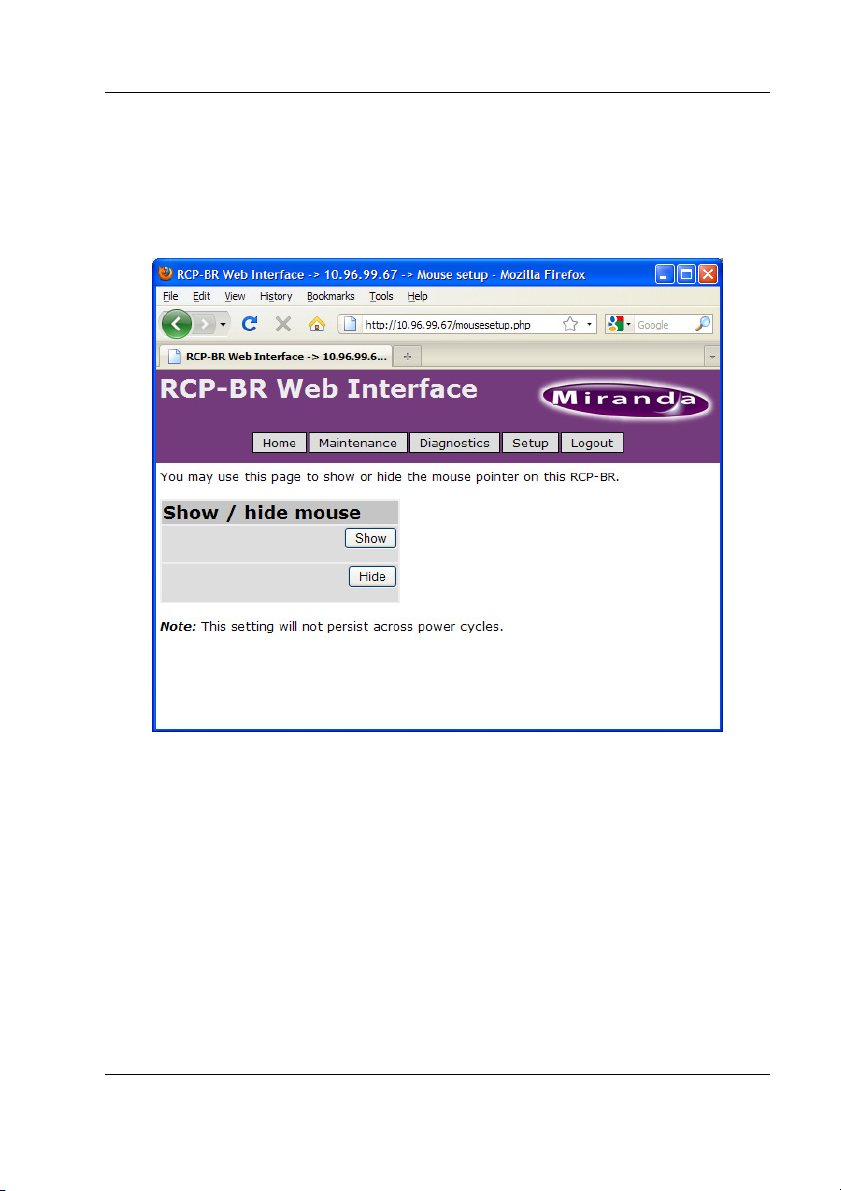
4.3.4 Mouse setup
By default the mouse pointer on the RCP-BR panel is turned off. If it is required
to display the mouse then this can be enabled in the ‘Mouse setup’ page.
Figure 4-18 Mouse pointer show/hide on the RCP-BR panel
The mouse pointer will be turned on or off as soon as the ‘Show’ or ‘Hide’
buttons are selected. Please note that when the unit is restarted the mouse pointer
will always revert back to being hidden.
Miranda Technologies Inc. Page 67
Page 76

RCP-BR: Guide to Installation and Operation
4.3.5 Serial number
Selecting the ‘Serial number setup’ option in the Setup list will display the current
serial number and when this was setup on the RCP-BR panel.
Figure 4-19 Display of the RCP-BR panel serial number
Page 68 Miranda Technologies Inc.
Page 77

RCP-BR: Guide to Installation and Operation
5 Installation
This section outlines the electrical, mechanical and environmental aspects of the
RCP-BR unit.
5.1 Mounting
RCP-BR ships with both “ears” and “30 degree desk-mounting” brackets.
Also available and sold separately:
• Rack-mount kit ( order code RCP-BR-RM-KIT, for 19” rack mounting )
• Desk-mount kit ( RCP-BR-DM-KIT, desk-mounting 60 degree brackets)
5.1.1 Mounting with ears
Figure 5-1 Mounting with ears - assembly
Miranda Technologies Inc. Page 69
Page 78

RCP-BR: Guide to Installation and Operation
Figure 5-2 Mounted with ears
Page 70 Miranda Technologies Inc.
Page 79

RCP-BR: Guide to Installation and Operation
5.1.2 Mounting with 30 degree brackets
Figure 5-3 Mounting with 30 degree bracket
Figure 5-4 Mounted with 30 degree bracket
Miranda Technologies Inc. Page 71
Page 80

RCP-BR: Guide to Installation and Operation
5.1.3 With 60 degree Desk-Mounting kit, RCP-BR-DM-KIT
The 60 degree Desk-Mounting Kit is sold separately - order RCP-BR-DM-KIT
Figure 5-5 Mounting with 60 degree Desk-Mounting Kit - assembly
Figure 5-6 Mounted with 60 degree Desk-Mounting kit
Page 72 Miranda Technologies Inc.
Page 81

RCP-BR: Guide to Installation and Operation
5.1.4 With Rack-Mounting kit, RCP-BR-RM-KIT
The Rack-Mounting Kit is sold separately – order code RCP-BR-RM-KIT
Figure 5-7 Mounting with Rack-Mounting kit - assembly
Figure 5-8 Rack-Mounted
Miranda Technologies Inc. Page 73
Page 82

RCP-BR: Guide to Installation and Operation
5.2 Ventilation
The RCP-BR unit is forced-air cooled. Air is drawn into the unit through holes at
the rear of the unit. Air is exhausted through holes both at the rear and along one
side of the unit.
Because air is drawn in from and exhausted back out into the rear, it is important
that air-space at the rear of the unit is well ventilated.
Note : It is essential that unit ventilation holes remain clear of obstruction.
Note : It is essential that the air-space at the rear of the unit is well-ventilated.
5.3 Power requirements
The RCP-BR unit is DC-powered via the supplied PSU AC power adapter. AC
mains voltage 90V-264VAC 47Hz-63Hz.
Power consumption:
RCP-BR unit 40W DC max.
RCP-BR unit & AC adapter 50W max.
Page 74 Miranda Technologies Inc.
Page 83

RCP-BR: Guide to Installation and Operation
5.4 RCP-BR rear connections
5.4.1 Summary
The RCP-BR rear connections are:
Name Connector Description
- - Metal earthing stud
DC power 8-pin DIN DC power, 12V from supplied power adapter
GPIO 15 way D-type
USB 2-off USB-A USB 2.0 connection for:
Ethernet RJ45 100baseT
This is not a VGA connector
4 opto-coupled GPI in/out*
* For later implementation.
Upgrade stick
Keyboard
Mouse
Miranda Technologies Inc. Page 75
Page 84

RCP-BR: Guide to Installation and Operation
5.4.2 DC power connector pinout (8 pin DIN, female)
The connector on the rear of the RCP-BR unit is:
Pin Number Pin function
1 GND
2 GND
3 +12V
4 GND
5 +12V
6 GND
7 +12V
8 +12V
Diagram of the DC power cable and cable connector of the power adapter
supplied with BR-RCP is:
Page 76 Miranda Technologies Inc.
Page 85

RCP-BR: Guide to Installation and Operation
5.4.3 GPIO pinout (15-way D-type)
GPIO ports are a future feature.
An active GPIO output is pulled low, ~0.8V. A 5V supply is available, but no
more than 500mA should be used. The supply is internally fused.
Pin Number Pin function
1 GPIO 1
2 GPIO 2
3 GPIO 3
4 GPIO 4
5,6,7,8 Ground Return
9 GPI +5V power, 500mA max, internally fused
10-15 Reserved
Recommend use of Miranda NSH15M 15way terminal adapter with this
connector.
This is NOT a VGA connector
Miranda Technologies Inc. Page 77
Page 86

RCP-BR: Guide to Installation and Operation
5.5 Mechanical
The RCP-BR unit is a ½ rack-width, 3RU 19” rack unit. It comes with rack
mounting ears and 30 degree mounting brackets.
Main unit dimensions:
• Height : 135mm approx.
• Width : 220mm approx. ( excluding “ears” )
265mm approx. ( including “ears” )
• Depth : 115mm approx. ( maximum )
• Weight : 2.0kg approx. ( RCP-BR unit with “ears” )
2.5kg approx. ( RCP-BR unit and AC power adapter )
• Cooling : Forced air via internal fan.
Fan air filter removable without removing RCP-BR casing.
Panel cut-out:
• 213mm x 129mm approx. ( without “ears” )
• 215mm x 129mm approx. ( with “ears” )
5.6 Environment
5.6.1 Operating
The RCP-BR unit operates in ambient conditions of 5oC to 40oC , where the
forced-air cooling temperature is 5oC to 40oC. Humidity 20%–80%, noncondensing.
Note : Temperature of air drawn into unit at rear must be 5oC to 40oC.
5.6.2 Storage
The RCP-BR storage temperature is -10 oC to +70 oC.
Page 78 Miranda Technologies Inc.
Page 87

RCP-BR: Guide to Installation and Operation
5.7 Other
5.7.1 RTC battery
The RCP-BR contains a back-up cell battery (3V CR2032 or equivalent ) for the
Real Time Clock and CMOS settings. Should this need replacing, contact
Miranda Customer Support and dispose of depleted battery in accordance with
local regulations.
5.7.2 Compact Flash
The RCP-BR contains a compact flash which stores all media and program
software. This is accessible through a small door in the rear of the unit. Ensure
unit is powered down before replacement of Compact Flash. Use only Mirandasupplied Compact Flash.
Miranda Technologies Inc. Page 79
 Loading...