

Page 1
AURORA INGEST
INGEST MANAGEMENT SYSTEM
System Guide
Software Version 7.0
071-8514-06
April 2010
Page 2

Affiliate with the N.V. KEMA in The Netherlands
CERTIFICATE
Certificate Number: 510040.001
The Quality System of:
Thomson Inc, and its worLdwide Grass Valley division affiliates DBA
GRASS VALLEY
Headquarters
400 Providence Mine Rd
Nevada City, CA 95959
United States
15655 SW Greystone Ct.
Beaverton, OR 97006
United States
10 Presidential Way
Suite 300
Woburn, MA 01801
United States
Kapittelweg 10
4827 HG Breda
The Nederlands
7140 Baymeadows Way
Ste 101
Jacksonville, FL 32256
United States
2300 So. Decker Lake Blvd.
Salt Lake City, UT 84119
United States
Rue du Clos Courtel
CS 31719
35517 Cesson-Sevigné Cedex
France
1 rue de l’Hautil
Z.I. des Boutries BP 150
78702 Conflans-Sainte
Honorine Cedex
France
Technopole Brest-Iroise
Site de la Pointe du Diable
CS 73808
29238 Brest Cedex 3
France
40 Rue de Bray
2 Rue des Landelles
35510 Cesson Sevigné
France
Spinnereistrasse 5
CH-5300 Turgi
Switzerland
Brunnenweg 9
D-64331 Weiterstadt
Germany
Carl-Benz-Strasse 6-8
67105 Schifferstadt
Germany
Including its implementation, meets the requirements of the standard:
ISO 9001:2008
Scope:
The design, manufacture and support of video and audio hardware and software products and
related systems
.
This Certificate is valid until: June 14, 2012
This Certificate is valid as of: June 14, 2009
Certified for the first time: June 14, 2000
H. Pierre Sallé
President
KEMA-Registered Quality
The method of operation for quality certification is defined in the KEMA General Terms
And Conditions For Quality And Environmental Management Systems Certifications.
Integral publication of this certificate is allowed.
KEMA-Registered Quality, Inc.
4377 County Line Road
Chalfont, PA 18914
Ph: (215)997-4519
Fax: (215)997-3809
CRT 001 073004
Accredited By:
ANAB
Page 3

AURORA INGEST
INGEST MANAGEMENT SYSTEM
System Guide
Software Version 7.0
071-8514-06
April 2010
Page 4

Copyright Copyright © Grass Valley, Inc. All rights reserved. Printed in the United States of America.
Portions of software © 2000 – 2010, Microsoft Corporation. All rights reserved. This document
may not be copied in whole or in part, or otherwise reproduced except as specifically permitted
under U.S. copyright law, without the prior written consent of Grass Valley, Inc., P.O. Box
59900, Nevada City, California 95959-7900. This product may be covered by one or more U.S.
and foreign patents.
SkinCrafter Component Copyright 2002-2005 DMSoft Technologies
Disclaimer Product options and specifications subject to change without notice. The information in this
manual is furnished for informational use only, is subject to change without notice, and should
not be construed as a commitment by Grass Valley, Inc. Grass Valley, Inc. assumes no
responsibility or liability for any errors or inaccuracies that may appear in this publication.
U.S. Government
Restricted Rights
Legend
Trademarks and
Logos
Revision Status
Use, duplication, or disclosure by the United States Government is subject to restrictions as set
forth in subparagraph (c)(1)(ii) of the Rights in Technical Data and Computer Software clause
at DFARS 252.277-7013 or in subparagraph c(1) and (2) of the Commercial Computer
Software Restricted Rights clause at FAR 52.227-19, as applicable. Manufacturer is Grass
Valley, Inc., P.O. Box 59900, Nevada City, California 95959-7900 U.S.A.
Grass Valley, K2, Aurora, Summit, Dyno, Solo, Infinity, Turbo, Profile, Profile XP, NetCentral,
NewsBrowse, NewsEdit, NewsQ, NewsShare, NewsQ Pro, and Media Manager are either
registered trademarks or trademarks of Grass Valley, Inc. in the United States and/or other
countries. Grass Valley, Inc. products are covered by U.S. and foreign patents, issued and
pending. Additional information regarding Grass Valley, Inc. trademarks and other proprietary
rights may be found at www.grassvalley.com. Other trademarks and logos used in this
document are either registered trademarks or trademarks of the manufacturers or vendors of
the associated products, such as Microsoft® Windows® operating system, Windows Media®
player, Internet Explorer® internet browser, and SQL Server™. QuickTime and the QuickTime
logo are trademarks or registered trademarks of Apple Computer, Inc., used under license
therefrom.
Rev Date Description
September 14,
2006
Initial release of the Aurora Ingest System Guide, 071-8514-00 for
Software Version 6.0. Updated from 071-8342-02, IngestStation
System Guide
January 18, 2007 Release 071-8514-01 for Software Version 6.0b
May 23, 2007 Release 071-8514-02 for Software Version 6.1
September 18,
2007
November 19,
2008
August 13, 2009 Release 071-8514-05 for Software Version 6.5.2
April 14, 2010 Release 071-8514-06 for Software Version 7.0
Release 071-8514-03 for Software Version 6.3
Release 071-8514-04 for Software Version 6.5
4 Aurora Ingest System Guide April 14, 2010
Page 5

Contents
Grass Valley Product Support..................................................................................................9
Chapter 1: Introducing Aurora Ingest......................................................................11
Introducing Aurora Ingest......................................................................................................12
About Aurora Ingest workstations..........................................................................................13
About Aurora Ingest applications...........................................................................................13
Integration with Aurora Suite and third-party products..........................................................14
Understanding Status Colors................................................................................................14
Chapter 2: Preparing for installation.......................................................................15
Installing Aurora Ingest .........................................................................................................16
About SiteConfig...................................................................................................................16
Aurora Ingest installation checklists......................................................................................17
Pre-installation planning checklist with SiteConfig.............................................................17
Hardware installation checklist...........................................................................................17
Network setup and implementation checklist.....................................................................18
Software update checklist..................................................................................................19
Contents
Chapter 3: Installing Aurora Ingest Hardware........................................................21
Installing RS-422 card for VTR Controller.............................................................................22
Installing video capture card (optional)..................................................................................22
Installing the X-keys Jog/Shuttle Controller ..........................................................................23
Chapter 4: Configuring the network........................................................................25
About developing a system description.................................................................................26
About the corporate LAN.......................................................................................................26
Configuring the corporate LAN..............................................................................................27
Adding a group......................................................................................................................27
Adding a device to the system description............................................................................28
About device and host names...............................................................................................29
Modifying a device name.......................................................................................................29
About IP configuration of network interfaces on devices.......................................................30
Placeholder device IP configuration...................................................................................30
Discovered device IP configuration....................................................................................30
Modifying unassigned (unmanaged) network interfaces on Aurora Ingest devices...............31
About SiteConfig support on Aurora Ingest devices..............................................................33
Discovering devices with SiteConfig......................................................................................33
Assigning discovered devices...............................................................................................34
Modifying Aurora Ingest device managed network interfaces...............................................35
Making the host name the same as the device name...........................................................40
Pinging devices from the control point PC.............................................................................40
About hosts files and SiteConfig...........................................................................................41
Generating host tables for devices with SiteConfig...............................................................41
14 April 2010 Aurora Ingest System Guide 5
Page 6

Contents
Chapter 5: Managing Software.................................................................................43
Create record of software installed on devices......................................................................44
Adding a software role to a device........................................................................................45
Removing a software role from a device...............................................................................45
Configuring deployment groups.............................................................................................45
Distribute devices into deployment groups............................................................................47
Check all currently installed software on Aurora Ingest devices............................................47
Add software package to deployment group for Aurora Ingest devices.................................48
Install prerequisite files on the control point PC....................................................................50
About deploying software......................................................................................................50
Backing up Aurora Ingest Database......................................................................................50
Migrating Aurora Ingest - Server...........................................................................................52
Restoring Aurora Ingest Database........................................................................................53
Installing Ingest software manually........................................................................................56
Installing ScheduALL for Aurora Ingest integration...............................................................56
Chapter 6: Configuring Aurora Ingest.....................................................................59
Configuring Aurora Ingest......................................................................................................60
Aurora Ingest - Server overview............................................................................................60
Configuring Aurora Ingest Server..........................................................................................61
Configuring System...........................................................................................................62
Setting up the K2, K2 Summit or M-Series iVDR server....................................................64
Configuring Media Servers................................................................................................64
Configuring a Router..........................................................................................................67
Configuring Channels .......................................................................................................81
Configuring Channel Group...............................................................................................83
Configuring Feed...............................................................................................................85
Configuring VTR................................................................................................................86
Configuring Preview Channel............................................................................................87
Configuring Scheduler application.........................................................................................88
Customizing color for Scheduler........................................................................................90
Customizing X-keys for Scheduler.....................................................................................92
Using the X-keys Jog/Shuttle Controller ...........................................................................94
Customizing video viewer for Scheduler............................................................................95
Configuring VTR Controller Application.................................................................................97
Troubleshooting VTR Controller configuration.................................................................100
Configuring VTR Ingest application.....................................................................................100
Setting up K2 Summit for RMI import..................................................................................103
Configuring RMI application................................................................................................105
Configuring user administration...........................................................................................109
Creating a group..............................................................................................................110
Creating users.................................................................................................................111
Modifying user settings....................................................................................................112
Removing user.................................................................................................................113
Modifying group settings..................................................................................................113
Removing group...............................................................................................................113
Configuring Aurora Ingest for ScheduALL...........................................................................113
Configuring ScheduALL properties .................................................................................114
Configuring ScheduALL for Aurora Ingest...........................................................................118
6 Aurora Ingest System Guide 14 April 2010
Page 7

Contents
Creating the Aurora Ingest Room....................................................................................118
Creating the Aurora Resource Category.........................................................................119
Creating Source and Channel Category Types................................................................120
Creating Source Resources.............................................................................................120
Creating Channel Resources...........................................................................................120
Creating the Aurora Resource Group..............................................................................121
Creating the Aurora Ingest Order Service.......................................................................121
Setting User Preferences.................................................................................................122
Adding Controls and Browsers to Dialogs in ScheduALL................................................122
Configuring ScheduALL application ................................................................................124
Chapter 7: Using Aurora Ingest - Scheduler.........................................................127
Using Aurora Ingest - Scheduler.........................................................................................128
Using Scheduler toolbar......................................................................................................129
Overview of clock and timeline............................................................................................130
Overview of channel window...............................................................................................130
Overview of Schedule Viewer..............................................................................................132
Crash Recording ................................................................................................................133
Scheduling recording ..........................................................................................................134
Adding New Events..........................................................................................................134
Adding New Events from CompuSat...............................................................................140
Modifying Events..............................................................................................................144
Extending Events.............................................................................................................144
Deleting Events................................................................................................................145
Using ENPS to schedule events......................................................................................145
Scheduling events between Scheduler and ScheduALL ................................................153
Creating a template.............................................................................................................160
Using filters..........................................................................................................................164
Using Channel Reservation.................................................................................................165
Using MediaFrame in Scheduler.........................................................................................166
Searching Assets.............................................................................................................166
About searching with filters .............................................................................................169
MediaFrame Character limitations...................................................................................170
Viewing recordings..............................................................................................................170
Using Live Feed Viewer...................................................................................................171
Selecting the Asset Viewer..............................................................................................172
Chapter 8: Using Aurora Ingest - VTR Controller.................................................175
Using VTR Controller...........................................................................................................176
Overview of the VTR Controller Window ............................................................................176
Viewing VTR Properties......................................................................................................176
Accessing VTR Controller...................................................................................................177
Chapter 9: Using Aurora Ingest - VTR Ingest........................................................179
Using VTR Ingest................................................................................................................180
Overview of the VTR Ingest window ...................................................................................180
Overview of clip record area............................................................................................181
Overview of channel window ..........................................................................................181
Recording with VTR Ingest..................................................................................................183
14 April 2010 Aurora Ingest System Guide 7
Page 8

Contents
Adding Handles ..............................................................................................................183
Creating a segment list ...................................................................................................183
Deleting the Segment List ...............................................................................................185
Controlling the VTR with VTR Ingest...............................................................................186
Marking In and Out Points ..............................................................................................186
Recording clips to the media server ...............................................................................187
Scanning tape with broken timecodes.................................................................................188
Importing an EDL................................................................................................................189
Exporting an EDL ...............................................................................................................189
Chapter 10: Using Aurora Ingest - RMI..................................................................191
Overview of RMI..................................................................................................................192
Using Aurora Ingest - RMI...................................................................................................193
Adding clips to groups.....................................................................................................194
Previewing clips...............................................................................................................194
Previewing and trimming a clip........................................................................................195
Editing clip properties and metadata...............................................................................196
Linking clips to Aurora Playout placeholders...................................................................199
Caching proxy assets.......................................................................................................200
Chapter 11: Linking Clips To Aurora Playout Placeholders.................................203
Linking clips to Aurora Playout placeholders.......................................................................204
Linking Clips .......................................................................................................................204
Creating New Placeholders ................................................................................................204
Appendix A: Aurora Ingest Appendix....................................................................207
Aurora Ingest keyboard shortcuts........................................................................................208
Aurora Ingest error messages.............................................................................................209
Appendix B: Software Licenses.............................................................................211
cmemdc...............................................................................................................................212
cping....................................................................................................................................212
CSizingToolBar....................................................................................................................213
CTextProgressCtrl...............................................................................................................214
MIT......................................................................................................................................214
mozilla.................................................................................................................................215
Paintlib.................................................................................................................................222
resizeable lib........................................................................................................................223
tconvert................................................................................................................................225
zlib.......................................................................................................................................225
Glossary.................................................................................................................................227
8 Aurora Ingest System Guide 14 April 2010
Page 9

Grass Valley Product Support
To get technical assistance, check on the status of a question, or to report a new issues,
contact Grass Valley Product Support via e-mail, the Web, or by phone or fax.
Web Technical Support
To access support information on the Web, visit the product support Web page on the
Grass Valley Web site. You can download software or find solutions to problems.
World Wide Web: http://www.grassvalley.com/support/
Technical Support E-mail Address: gvgtechsupport@grassvalley.com
Telephone Support
Use the following information to contact Product Support by phone.
International Support Centers
Our international support centers are available 24 hours a day, 7 days a week.
Authorized Local Support Representative
A local support representative may be available in your country. To locate a support
center during normal local business hours, refer to the following list. This list is
regularly updated on the website for Grass Valley Product Support
(http://www.grassvalley.com/support/contact/phone/)
After–hours local phone support is also available for warranty and contract customers.
Macau
In countryToll freeSupport Center
+33 1 48 25 20 20+800 80 80 20 20France
+1 530 478 4148+1 800 547 8949United States
TelephoneCountyRegion
+86 10 5883 7575ChinaAsia
+852 2531 3058Hong Kong, Taiwan, Korea,
+81 3 6848 5561Japan
+603 7492 3303Southeast Asia - Malaysia
+65 6379 1313Southeast Asia - Singapore
14 April 2010 Aurora Ingest System Guide 9
Page 10

Grass Valley Product Support
South America
TelephoneCountyRegion
+91 22 676 10300India
1 300 721 495AustraliaPacific
0800 846 676New Zealand
+61 3 8540 3650For callers outside Australia
or New Zealand
+55 11 5509 3440AllCentral America,
North America
North America, Mexico,
Caribbean
France
Eastern Europe
Belarus, Russia,
Tadzhikistan, Ukraine,
Uzbekistan
Nordics (Norway, Sweden,
Finland, Denmark, Iceland)
Southern Europe – Italy
+1 800 547 8949;
+1 530 478 4148
+44 118 923 0499UK, Ireland, IsraelEurope
+31 (0) 35 62 38 421Benelux – Netherlands
+32 (0) 2 334 90 30Benelux – Belgium
+800 80 80 20 20;
+33 1 48 25 20 20
+49 6150 104 444Germany, Austria,
+7 095 258 09 20;
+33 (0) 2 334 90 30
+45 40 47 22 37; +32 2 333
00 02
Rome: +39 06 87 20 35 28 ;
+39 06 8720 35 42. Milan:
+39 02 48 41 46 58
+34 91 512 03 50Southern Europe – Spain
+41 56 299 36 32Switzerland
+971 4 299 64 40Middle EastMiddle East, Near East,
Africa
10 Aurora Ingest System Guide 14 April 2010
Near East and Africa
+800 80 80 20 20;
+33 1 48 25 20 20
Page 11

Chapter 1
Introducing Aurora Ingest
This section contains the following topics:
• Introducing Aurora Ingest
• About Aurora Ingest workstations
• About Aurora Ingest applications
• Integration with Aurora Suite and third-party products
• Understanding Status Colors
14 April 2010 Aurora Ingest System Guide 11
Page 12
Introducing Aurora Ingest
Introducing Aurora Ingest
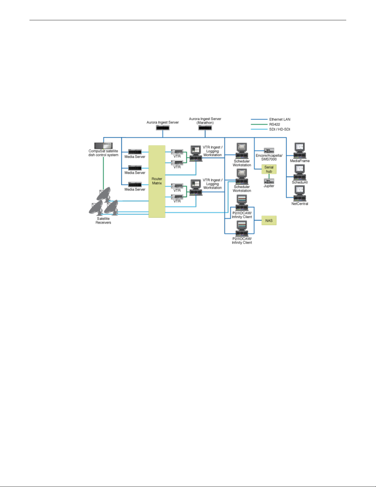
Aurora Ingest is an automated media digitization system, made up of several integrated
applications, that allows you to ingest footage from VTRs, feeds from a router, or files
from multiple Digital Media Cameras and Digital Media Recorders, all directly to a
media server in your operation.
The Aurora Ingest system supports the K2 Media Server and Media Client system,
K2 Summit Production Client system and M-Series iVDR (Intelligent Video Disk
Recorder). You can configure your system to record clips into two servers in parallel.
If one server fails or has inadequate storage, only the recording on that server will be
stopped. When the system continues to the next clip, the storage capacity on both
servers is checked again, allowing parallel recording to resume if storage is made
adequate.
Raw footage comes from a VTR connected directly to the Aurora Ingest workstation,
a CompuSat satellite dish control system, a router source or a removable media device.
While you connect the media servers to the Aurora Ingest workstation using AMP
Sockets, you need RS-422 connection from the VTR to the Aurora Ingest workstation
to have control of the VTR in the Aurora Ingest windows. For router sources, Aurora
Ingest supports the SMS 7000, Acappella, Encore control and Jupiter systems. For
removable media, Aurora Ingest supports devices such as Infinity, Panasonic P2, Sony
XDCAM and JVC.
The integration of MediaFrame with Aurora Ingest adds asset management feature
and metadata capabilities to the system. With MediaFrame asset management tools,
users can apply, add, edit and search metadata of assets created within the ingest
process. Users can also play low-resolution video versions of ingested assets. Aurora
Ingest Server monitors the connection to the MediaFrame server, displays the
connection status and attempts to reconnect when the connection is broken. MediaFrame
12 Aurora Ingest System Guide 14 April 2010
Page 13

components are also utilized in Aurora Ingest components such as Scheduler, VTR
Ingest and RMI.
About Aurora Ingest workstations
Aurora Ingest has a client/server architecture that allows for multiple simultaneous
users. It supports simultaneous event creation, event modification, event deletion,
event monitoring, and resource viewing from multiple workstations.
Each workstation can control up to eight VTRs for batch list creation and batch ingest.
You can work with either directly attached VTRs and dedicated server ports or through
a router.
You can trigger multiple channel records from disparate sources simultaneously and
schedule record events without reference to physical server port. Aurora Ingest
automatically allocates any available port as determined at the optimum time before
the record event is scheduled to begin. RS-422 router level control allows any
router-connected VTR to be controlled by any Aurora Ingest channel.
Introducing Aurora Ingest
About Aurora Ingest applications
Aurora Ingest consists of the following applications:
• Aurora Ingest Server lets you configure the other Aurora Ingest applications for
batch or feed events, as well as monitor the status of the media servers, database
server, MediaFrame server, routers, CompuSat satellite dish control system, and
channels. You can also access logs and manage user accounts for Aurora Ingest
clients.
• VTR Controller lets you monitor and manage the VTRs you use with VTR Ingest.
• VTR Ingest lets you ingest footage from VTRs and import or export Edit Decision
Lists (EDLs). Supporting up to eight channels, VTR Ingest can record footage with
configurable handle durations. It lets you set VTR mark points using either the PC
keyboard or the mouse. You can ingest a single item or build a batch list of items
to capture from multiple tapes. You can also create a batch list offline and then
import the list into VTR Ingest as a common EDL. Once you create a batch list,
you can optimize the list by timecode, which allows the material to be ingested in
the shortest time possible, or manually arrange the batch list items in order to
prioritize immediately needed clips.
• Scheduler lets you schedule ingest feed events from a media server, CompuSat
satellite dish control system, VizuAll Inc.'s ScheduALL application, router source
or VTR. You can also schedule events to record, up to three years in advance, on
each server channel, including recurring events. Schedule Viewer provides an
easily readable way to see all channels and more specifically the task assigned to
each channel.
14 April 2010 Aurora Ingest System Guide 13
Page 14

Introducing Aurora Ingest
• Removable Media Interface (RMI) lets you ingest files from multiple Infinity
Digital Media Cameras and Digital Media Recorders, as well as Sony XDCAM
and Panasonic P2 removable media devices.
If you use Aurora Playout as a playback system in your operation, you can ingest clips
directly to an Aurora Playout rundown by linking clips to an Aurora Playout placeholder
at the point of scheduling a record or importing a removable media.
Integration with Aurora Suite and third-party products
Aurora Ingest is integrated with other applications in the Aurora Suite and third-party
products.
In addition to serving as a metadata entry and transfer application for metadata created
in the newsroom computer system (NCS), it supports:
• Mark In/Out of incoming feed material, allowing direct assignment of field-edited
material to Aurora Playout placeholders.
• Add, apply, search, edit metadata of assets and play low-resolution video versions
of ingested assets via the MediaFrame plug-in, an asset management tool utilized
by all products within Aurora Suite.
• Scheduling integration with VizuAll, Inc.'s ScheduALL application, enabling events
scheduled on Aurora Ingest to appear on ScheduALL and vice versa.
Understanding Status Colors
Each event entry displays a certain color according to its status.
DescriptionRow Background Color
The entry is recording.Red
The entry is cued and is next to record.Gold
The entry has finished recording.Green
The Scheduler entry is ready to record.Blue
Black
Purple
Gray
Users can customize status color of events in Aurora Ingest - Scheduler by changing
the color configuration in the Scheduler application.
The channel is reserved for a specific recording at that
time.
The entry failed to record. See the Error Message field for
more information.
The entry time has elapsed, probably due to a conflict with
another recording.
14 Aurora Ingest System Guide 14 April 2010
Page 15

Chapter 2
Preparing for installation
This section contains the following topics:
• Installing Aurora Ingest
• About SiteConfig
• Aurora Ingest installation checklists
14 April 2010 Aurora Ingest System Guide 15
Page 16

Preparing for installation
Installing Aurora Ingest
Grass Valley supplies a CD containing Aurora Ingest software and documentation.
For some of the Aurora Ingest components, Grass Valley also supplies hardware.
The Aurora Ingest - Server can be supplied with all the necessary hardware and software
installed. The software for the other Aurora Ingest components can be installed on
any PC which meets the system requirement for that component. After installing
Aurora Ingest, the software license number needs to be obtained. Refer to Aurora
Ingest Release Notes for instructions on obtaining the software license number.
For initial install of Aurora Ingest within your operation, SiteConfig is the
recommended tool for network configuration and software deployment. For upgrading
Aurora Ingest from a previous version, you can either upgrade using SiteConfig or
upgrade manually using the Aurora Ingest CD. Refer to Aurora Ingest Release Notes
for detailed instructions on upgrading Aurora Ingest.
About SiteConfig
ProductFrame is an integrated platform of tools and product distribution processes for
system installation and configuration. SiteConfig is a ProductFrame application and
it is the recommended tool for network configuration and software deployment.
You can use SiteConfig as a stand-alone tool for planning and system design, even
before you have any devices installed or cabled. You can define networks, IP addresses,
hostnames, interfaces, and other network parameters. You can add devices, group
devices, and modify device roles in the system.
As you install and commission systems, SiteConfig runs on the control point PC. It
discovers devices, configures their network settings, and manages host files. SiteConfig
also manages software installations and upgrades and provides a unified software
package with verified compatible versions for deployment across multi-product systems.
You should use SiteConfig for network configuration and software deployment at
installation and throughout the life of the system in your facility. This enforces
consistent policy and allows SiteConfig to keep a record of changes, which makes the
system easier to maintain and aids in troubleshooting should a problem arise.
SiteConfig displays information from a system description file, which is an XML file.
SiteConfig operates in different modes that correspond to a system’ s life-cycle phases:
network configuration, software deployment, and software configuration. You can
expand nodes and select elements in the tree view and the list view to view and modify
networks, systems, individual devices, software deployment, and configuration settings.
16 Aurora Ingest System Guide 14 April 2010
Page 17
Aurora Ingest installation checklists
Use the following sequence of checklists to guide the overall task flow of installing
and commissioning an Aurora Ingest system.
Pre-installation planning checklist with SiteConfig
CommentTask
—Get the Aurora Ingest Software CD
Preparing for installation
Check hardware specification
requirements for Aurora Ingest
components
Install SiteConfig on a control point PC
within your network operation
Get Grass Valley software prerequisite
file
Get Aurora Ingest software installation
(*.cab) file
Get GVG_MLib (*.cab) file for Aurora
Ingest Server installation
Get GVG_MLib, Generic iSCSI and
Aurora Suite (*.cab) files for RMI
installation
Next: Hardware installation checklist
Hardware installation checklist
The minimum and recommended system
specification requirements are listed in
Aurora Ingest Release Notes
Before you install SiteConfig, you would
need to create a system description for
the system if there isn't one already
installed
Make the prerequisite file accessible to
the SiteConfig control point PC
Make the (*.cab) file accessible to the
SiteConfig control point PC
Make the (*.cab) file accessible to the
SiteConfig control point PC
Make those (*.cab) files accessible to the
SiteConfig control point PC
Use items in this checklist as appropriate for the optional equipment you are installing
for your Aurora Ingest.
CommentTask
Install RS-422 card for VTR Controller
Next: Network setup and installation checklist
14 April 2010 Aurora Ingest System Guide 17
Alternately, a VTR can be attached to
the VTR Controller PC's COM1 port
using an RS-422 to RS-232 cable.
—Install video capture card
—Install X-keys Jog/Shuttle Controller
Page 18

Preparing for installation
Network setup and implementation checklist
CommentTask
Add corporate LAN to system
description
devices to the system description
description for each of your actual
Aurora Ingest devices
devices
Configure the network interfaces of the
placeholder devices
placeholder device
For each discovered and assigned device,
edit each network interface. Specify
network settings and apply them to the
device.
Create a new system description, if you
don't have one. If you have K2 SAN
within your operation, modify your K2
SAN system description.
—Add a group for your Aurora Ingest
—Add a placeholder device to the system
—Configure the names of the placeholder
Specify IP address ranges and other
network details
—Discover your Aurora Ingest devices
—Assign each discovered device to its
If a device connects to multiple networks,
set the control network interface IP
address first. Also set the hostname.
If not already set correctly, set the
hostname of discovered devices
network communication
Generate host table information and
distribute to hosts files on each device
and on the control point PC across all devices to ensure complete and
Next: Software update checklist
Make sure the device name is correct,
then make the hostname the same as the
device name.
—Ping each Aurora Ingest device to test
Make sure you have completed network
configuration of all network interfaces
valid host table information. You can use
SiteConfig to copy hosts files to devices,
or you can manage hosts files yourself.
18 Aurora Ingest System Guide 14 April 2010
Page 19
Software update checklist
Preparing for installation
CommentTask
Add/remove software roles
deployment group
Place software on control point PC
Check software on devices
Add software to deployment group
Set deployment options
Upgrade/install software to devices from
control point PC
Make sure software roles match the
software that should be installed on each
device, according to your system design.
—Create a deployment group
—Add Aurora Ingest devices to the
Procure the correct version of software
installation files and prerequisite files.
Refer to the release notes for your
product.
14 April 2010 Aurora Ingest System Guide 19
Page 20

Page 21

Chapter 3
Installing Aurora Ingest Hardware
This section contains the following topics:
• Installing RS-422 card for VTR Controller
• Installing video capture card (optional)
• Installing the X-keys Jog/Shuttle Controller
14 April 2010 Aurora Ingest System Guide 21
Page 22

Installing Aurora Ingest Hardware
Installing RS-422 card for VTR Controller
For VTR Controller, Grass Valley supplies a RocketPort Plus Universal PCI 422
SMPTE 8 Port RoHS RS-422 card that must be installed.
1. If you are connecting one or more VTRs to VTR Controller, install the RS-422
card in your computer, making sure the dip switches are set to the down position
as shown, and install the card’s driver.
NOTE: If only one VTR is to be connected to a VTR Controller PC, you can
use an alternative connection method with an RS-422 to RS-232 cable
connected to the onboard COM1 port.
2. Connect the VTR(s) to the VTR Controller machine via RS-422.
3. If you are using LTC for timecode, connect a timecode cable from the timecode
source (VTR for VTR Ingest, Timecode Generator for Aurora Ingest - Scheduler)
to the media server.
4. Without the LTC physical connection, timecodes could still be polled via RS-422.
Check the option to enable RS-422 timecode mode within Tools|Options of VTR
Controller application.
Installing video capture card (optional)
You can either install Hauppage WinTV-HVR-1150 Video Capture Card or Blackmagic
Design DeckLink Video Capture Card to view clips on Aurora Ingest clients. Check
for minimum system requirements needed before choosing and purchasing your video
capture card.
Both video capture cards are for SD (standard definition) video only. If you want to
view incoming HD video, first downconvert the media from HD to SD.
For Hauppage WinTV-HVR-1150 video capture card, you have to then convert from
digital to analog. The video capture card accepts composite analog video only (NTSC
or PAL).
For Blackmagic Design DeckLink video capture card, SDI input and output with
embedded audio are supported. For audio monitoring, you could also connect SPDIF
output to your audio peripheral.
1. Install the video capture card in your machine and install the card’s driver. Refer
to the manufacturer’s manual for installation instructions.
22 Aurora Ingest System Guide 14 April 2010
Page 23

2. For Hauppage WinTV-HVR-1150 video capture card, connect the device you're
using for a video source (VTR, router or switch box) to the Hauppage composite
video input connector.
3. For Blackmagic Design DeckLink video capture card, connect SDI Output from
your media server or router to SDI Input connector of the video capture card.
4. If you have a video capture card installed in your machine and a router configured
in your system, select the router destination from the dropdown list within
Tools|Options|Video Viewer of the Scheduler or VTR Ingest.
After the video capture card has been successfully configured, it could be selected
from the Capture Device dropdown list within Tools|Options|Video Viewer of the
Scheduler or VTR Ingest.
Installing the X-keys Jog/Shuttle Controller
You can install the X-keys Jog/Shuttle controller if you want to use the device with
Aurora Ingest Scheduler.
Installing Aurora Ingest Hardware
Aurora Ingest has been designed to work with the X-keys Jog/Shuttle controller (model
XPS-08-USB) with MWII panels.
1. Plug the X-keys Jog/Shuttle controller into a USB connector on the Scheduler
machine.
2. On the Scheduler machine, insert the X-keys Macro Works installation CD and
follow the instructions. Do not check the box to put shortcuts on the desktop.
If AutoRun is not enabled on your CD-ROM drive, find the file "ainstall.exe"
on the installation CD and run it.
3. Reboot the computer when prompted.
4. When the installation has completed, the X-keys Macro Maker and Macro Manager
windows automatically pop up. Close these windows.
5. Start Aurora Ingest Server and Aurora Ingest Scheduler.
6. In the Scheduler Tools menu, select Options.
7. Select the X-keys tab.
8. Verify the “Enable X-keys” box is checked and click OK.
You can customize the X-keys to suit your needs.
14 April 2010 Aurora Ingest System Guide 23
Page 24

Page 25

Chapter 4
Configuring the network
This section contains the following topics:
• About developing a system description
• About the corporate LAN
• Configuring the corporate LAN
• Adding a group
• Adding a device to the system description
• About device and host names
• Modifying a device name
• About IP configuration of network interfaces on devices
• Modifying unassigned (unmanaged) network interfaces on Aurora Ingest devices
• About SiteConfig support on Aurora Ingest devices
• Discovering devices with SiteConfig
• Assigning discovered devices
• Modifying Aurora Ingest device managed network interfaces
• Making the host name the same as the device name
• Pinging devices from the control point PC
• About hosts files and SiteConfig
• Generating host tables for devices with SiteConfig
14 April 2010 Aurora Ingest System Guide 25
Page 26

Configuring the network
About developing a system description
The topics in this manual assume that you are modifying an existing system description.
Your system description is typically developed using one of the following taskflows:
• For a system in which all devices are new from Grass Valley with one or more K2
• For a system in which all devices are new from Grass Valley with one or more
• For a system with existing devices running earlier software, you must first migrate
SANs, you first create a system description for your K2 SAN or SANs, then add
Browse/MediaFrame, Edit, Ingest, and Playout devices as appropriate. Refer to
the K2 SAN installation and Service Manual for instructions on creating the system
description.
stand-alone K2 systems, you first create a system description and add your
stand-alone K2 systems, than add other devices as appropriate. Refer to the K2
System Guide for instructions on creating the system description and adding your
stand-alone K2 systems.
the system to become a SiteConfig managed system. Refer to SiteConfig Migration
Instructions for instructions on migrating your devices to be SiteConfig managed
devices.
If you are using a different taskflow, use the topics in this manual as appropriate and
refer to the SiteConfig User Manual or SiteConfig Help Topics for additional
information.
Your devices must be in a SiteConfig system description in order to be managed by
SiteConfig. When you already have a system description in place, you should use
SiteConfig to modify this system description and add your devices. You can do this
in your planning phase, even before you have devices installed or cabled. Your goal
is to have the SiteConfig system description accurately represent all aspects of your
devices and networks before you begin actually implementing any networking or other
configuration tasks for those devices.
About the corporate LAN
Devices such as the Aurora Ingest Server, Scheduler, RMI, VTR Controller and VTR
Ingest workstations can be on the corporate LAN, which is considered an unmanaged
network in SiteConfig. You can configure your system description to include the
corporate LAN for the following purposes:
• If a device, such as the Aurora Ingest Server, is on the corporate LAN yet is a
SiteConfig managed device, then SiteConfig needs to know the connection for
each network interface on the device, including the corporate LAN connection.
Otherwise, SiteConfig displays error messages.
• If a device uses a DNS server on the corporate LAN for name resolution, SiteConfig
needs to reference that DNS server.
26 Aurora Ingest System Guide 14 April 2010
Page 27

• If a device has software that SiteConfig supports and the devices is on the corporate
LAN, such as Scheduler, RMI, VTR Controller and VTR Ingest workstations, you
can use SiteConfig to deploy software to the device via the corporate LAN.
If the device is on the corporate LAN and is not on a network that is managed by
SiteConfig, you cannot configure network settings on the device.
Configuring the corporate LAN
1. In the Network Configuration | Networks tree view, select a System node or a Site
node.
The networks under that node are displayed in the list view.
2. Proceed as follows:
• To add a network under the currently selected node, in the tree view right-click
the node and select Add Network.
Configuring the network
The Network Settings dialog box opens.
3. Configure the settings for the network as follows:
• Type – Select Ethernet
• Usage – Select Control
• Redundancy – Select None
• Name – Enter a name to identify the network in the system description
• Exclude from Host Files – Select the checkbox
• Unmanaged – Select this option, then select DNS and select the checkbox for
IP Address Allocation via DHCP.
• Base IP Address – Do not configure
• Number of IP Addresses – Do not configure
• Subnet Mask – Do not configure
• DNS Servers – Servers providing DNS for name resolution. These DNS server
can be for both managed and unmanaged networks.
• Default Interface Name Suffix – The suffix added to the end of host names to
identify interfaces on this network.
4. Click OK to save settings and close.
5. If you added a network, it appears in the Network Configuration | Networks tree
view at the bottom of the list.
Adding a group
1. In the Network Configuration | Networks tree view, right-click a site node and select
Add Group.
14 April 2010 Aurora Ingest System Guide 27
Page 28
Configuring the network
2. Right-click the group and select Rename.
3. Enter the desired name for the group.
Adding a device to the system description
Prerequisites for this task are as follows:
• The system description contains a group.
1. In the Network Configuration | Devices tree view, right-click a group and select Add
The group appears in the tree view.
Device.
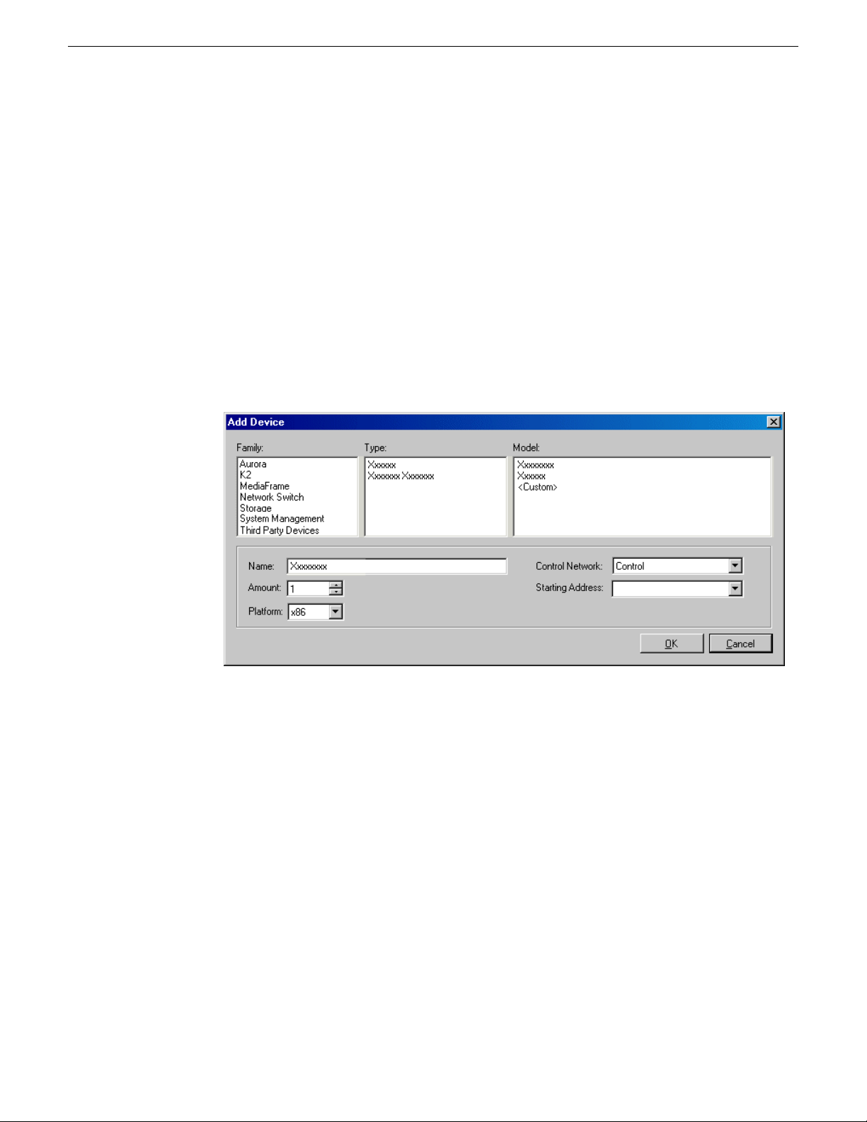
The Add Device dialog box opens.
2. Configure settings for the device you are adding as follows:
• Family – Select Aurora.
• Type – Select Aurora Ingest Platform.
• Model – Select the appropriate Aurora Ingest components.
• Name – This is the device name, as displayed in the SiteConfig device tree view
and device list view. This name can be different than the host name (network
name). You can accept the default name or enter a name of your choice. Devices
in the tree view are sorted alphabetically.
• Amount – You can add multiple devices, as currently defined by your settings
in the Add Device dialog box. An enumerator is added to the name to create a
unique name for each device added.
• Control network – Select the control network.
28 Aurora Ingest System Guide 14 April 2010
Page 29

• Starting Address – Select from the list of available addresses on the selected
control network. If adding multiple devices, this is the starting address, with
addresses assigned sequentially to each device added.
3. Click OK to save settings and close.
4. Repeat these steps for each of your devices.
About device and host names
In SiteConfig, a device can have different names, as follows:
• Device name — This is a name for display in SiteConfig only. It is stored in the
SiteConfig system description, but not written to the actual device. It is displayed
in the device tree view and in the device list view. It can be a different name than
the device’s host name.
• Host name — This is the network name of the device. SiteConfig has a default
naming convention for host names which you can use or override with your own
host names.
Configuring the network
In most cases it is recommended that the Device name and Host name be the same.
This avoids confusion and aids troubleshooting.
The Device name can serve as a placeholder as a system is planned and implemented.
During the install/commission process, when you reconcile a device's current and
planned network interface settings, the Host name as configured in the system
description can be overwritten by the host name on the actual device. However, the
Device name configured in the system description is not affected. Therefore it is
recommended that in the early planned stages, you configure the Device name to be
the desired name for the device, but do not yet configure the Host name. Then, after
you have applied network interface settings, you can change the Host name to be the
same as the Device name. This changes the host name on the actual device so that
then all names are in sync.
SiteConfig does not allow duplicate device names or host names.
Items in the tree view are automatically sorted alphabetically, so if you change a name
the item might sort to a different position.
Modifying a device name
1. In the Network Configuration | Devices tree view, right-click a device and select
Rename.
2. Type in the new name.
Note that this does not change the hostname on the physical device. If you want
the hostname to match the device name, you must also modify the hostname.
14 April 2010 Aurora Ingest System Guide 29
Page 30
Configuring the network
About IP configuration of network interfaces on devices
You can perform IP configuration of network interfaces when working with a
placeholder device prior to discovery. When you add a device and choose a particular
model, the model defines the number, type and usage characteristics of network
interfaces to expect on such a device.
You can view and edit each network interface and set up IP configuration selecting
an appropriate IP from the network to which each interface connects. The process for
editing IP configuration varies, depending on the device's phase.
Placeholder device IP configuration
On a placeholder device, you edit network interfaces using the Unmanaged Network
Interfaces dialog box.
The Unmanaged Network Interfaces dialog box allows you only to save changes to
the system description.
Discovered device IP configuration
On a discovered device, you edit network interfaces using the Managed Network
Interfaces dialog box.
30 Aurora Ingest System Guide 14 April 2010
Page 31

Configuring the network
The Managed Network Interfaces dialog box allows you to edit and save changes to
the device.
Modifying unassigned (unmanaged) network interfaces on Aurora Ingest devices
Prerequisites for this task are as follows:
• The system description has one or more Aurora Ingest devices that are placeholder
devices.
• The placeholder device has a one or more unmanaged network interfaces.
Use this task to modify unmanaged network interfaces on Aurora Ingest devices as follows:
• Aurora Ingest Server
• RMI
• RS 422 Control of VTRs
• Scheduler
• VTR Ingest
14 April 2010 Aurora Ingest System Guide 31
Page 32

Configuring the network
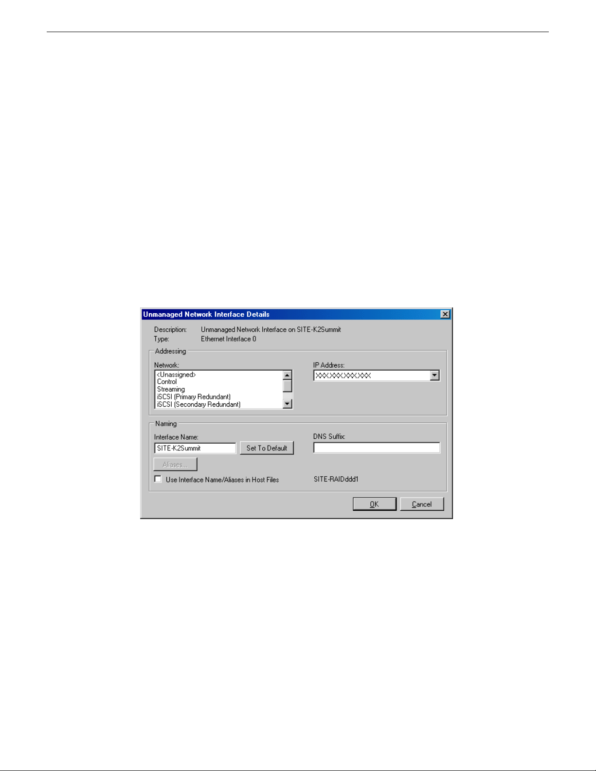
1. In the Network Configuration | Devices tree view, select an Aurora Ingest placeholder
2. In the interfaces list view, right-click an interface and select Edit.
device.
The interfaces for that device are displayed in the interfaces list view.
The Unmanaged Network Interface Details dialog box opens.
3. Configure the settings for the interface as follows:
Setting...
Name
Set to Default
Use Interface
Name/Aliases
in Host Files
DNS Suffix
For control network interface
Control is requiredNetwork
The IP address for this interface on the network. Required.IP Address
The device host name. Required.Interface
Not recommended. Sets the interface name to SiteConfig default
convention, based on the root Site name and device-type.
Unselected is required. Since not selected, the default behavior
occurs, which is to use the device host name in the hosts file.
Not allowedAliases
Allowed, if applicable to the network. The DNS suffix is added to
the interface name.
32 Aurora Ingest System Guide 14 April 2010
Page 33

Configuring the network
4. Click OK to save settings and close.
5. If configuring an Aurora Ingest device that is also on the corporate LAN, repeat
steps to configure an interface for the corporate LAN, with settings as follows:
Setting...
Network
Interface
Name
Set to Default
Use Interface
Name/Aliases
in Host Files
Aliases
DNS Suffix
For corporate LAN network interface
If using DHCP or external hosts file, select the unmanaged network
that you configured earlier.
Select the IP address you plan to assign to the device.IP Address
These settings are irrelevant, as SiteConfig does not manage this
network.
For communication on some networks, a suffix, such as
mycorp.com, must be added to host names.
6. Click OK to save settings and close.
About SiteConfig support on Aurora Ingest devices
Before SiteConfig can be used to discover or manage a device, the device must meet
the following requirements:
• The device must be a Microsoft Windows operating system device.
• The device must have Microsoft .NET version 2.0 installed, as reported in the
Windows Add/Remove Programs control panel.
• The ProductFrame Discovery Agent service must be running on the device, as
reported in the Windows Services control panel.
For Aurora Ingest devices shipped new from Grass Valley with software version 6.5.2
or higher, these requirements are pre-installed. These requirements are pre-installed
on recovery images for these systems as well. Therefore, if you suspect a problem
with these requirements, do not attempt to install SiteConfig support requirements. If
you must restore SiteConfig support requirements, re-image the system.
Discovering devices with SiteConfig
Prerequisites for this task are as follows:
• The Ethernet switch or switches that the support the control network are configured
and operational. If multiple switches, ISLs are connected and trunks configured.
14 April 2010 Aurora Ingest System Guide 33
Page 34

Configuring the network
• The control point PC is communicating on the control network.
• There are no routers between the control point PC and the devices to be discovered.
• Devices to be discovered are Windows operating system devices, with SiteConfig
• Devices are cabled for control network connections.
1. Open SiteConfig on the control point PC.
2. In the toolbar, click the discover devices button.
support installed.
The Discover Devices dialog box opens.
A list of discovered devices is displayed.
3. Click Rescan to re-run the discovery mechanism. You can do this if a device that
you want to discover has its network connection restored or otherwise becomes
available. Additional devices discovered are added to the list.
Assigning discovered devices
Prerequisites for this task are as follows:
• Devices have been discovered by SiteConfig
• Discovered devices are not yet assigned to a device in the system description
• The system description has placeholder devices to which to assign the discovered
devices.
1. If the Discovered Devices Dialog box is not already open, click the discover devices
button .
34 Aurora Ingest System Guide 14 April 2010
Page 35

Configuring the network
The Discover Devices dialog box opens.
2. Identify discovered devices.
• If a single device is discovered in multiple rows, it means the device has multiple
network interfaces. Choose the interface that represents the device's currently
connected control connection. This is typically Ethernet ... 0.
• If necessary, select a device in the list and click ID Device. This triggers an action
on the device, such as flashing an LED or ejecting a CD drive, to identify the
device.
3. To also view previously discovered devices that have already been assigned to a
device in the system description, select Show … currently assigned devices.
The currently assigned devices are added to the list. Viewing both assigned and
unassigned devices in this way can be helpful to verify the match between
discovered devices and placeholder devices.
4. In the row for each discovered device, view items on the Device Id drop-down list
to determine the match with placeholder devices, as follows:
• If SiteConfig finds a match between the device-type discovered and the
device-type of one or more placeholder devices, it displays those placeholder
devices in the list.
• If SiteConfig does not find a match between the device-type discovered and the
device-type of a placeholder device, no placeholder device is displayed in the
list.
5. In the row for a discovered device, click the Device Id drop-down list and select
the placeholder device that corresponds to the discovered device.
If there is no corresponding placeholder device currently in the system
description, you can select Add to create a new placeholder device and then
assign the discovered device to it.
6. When discovered devices have been assigned, click OK to save settings and close.
7. In the Network Configuration | Devices tree view, select each of the devices to which
you assigned a discovered device.
Modifying Aurora Ingest device managed network interfaces
Prerequisites for this task are as follows:
• The physical device you are configuring has been discovered and is assigned to a
device in the SiteConfig system description.
• SiteConfig has communication with the device.
• The device is defined in the system description with an appropriate network
interface.
14 April 2010 Aurora Ingest System Guide 35
Page 36

Configuring the network
Use this task to modify managed network interfaces on Aurora Ingest devices:
1. In the Interfaces list view determine the interface to configure, as follows:
2. In the Interfaces list view, check the icon for the interface you are configuring.
• Identify the interface with which SiteConfig is currently communicating,
indicated by the green star overlay icon. This should be the control network
interface.
• Verify that the interface over which SiteConfig is currently communicating is
in fact the interface defined for the control network in the system description.
If this is not the case, you might have the control network cable connected to
the wrong interface port. The control connection should always be the first port
on the motherboard, except when you have a loopback connection.
• Configure the control network interface first before configuring any of the other
interfaces.
• After you have successfully configured the control network interface, return to
this step to configure each remaining interface.
If the icon has a red stop sign overlay, it indicates that current settings and
planned settings do not match or that there is some other problem. Hover over
the icon to read a tooltip with information about the problem.
3. In the Interfaces list view, right-click the interface you are configuring and select
Edit.
The Managed Network Interface Details dialog box opens.
36 Aurora Ingest System Guide 14 April 2010
Page 37

Configuring the network
4. Identify the interface on the discovered device that you are configuring.
• Identify Ethernet LAN adapters by their "Description" name. This is the
Windows connection name. SiteConfig reads this name from the device and
displays it at the top of this dialog box. This is the most accurate way to identify
the network adapter on the discovered device that you are configuring.
5. Configure naming settings as follows:
For network interface Network ConnectionSetting...
The device host name. Required.Interface
Name
Not recommendedSet To Default
DNS Suffix
Allowed, if applicable to the network. The DNS suffix is added to
the interface name.
Not allowedAliases
14 April 2010 Aurora Ingest System Guide 37
Page 38

Configuring the network
For network interface Network ConnectionSetting...
Use Interface
Name/Aliases
in Host Files
Name
DNS Suffix
Use Interface
Name/Aliases
in Host Files
Unselected is required. Since not selected, the default behavior
occurs, which is to use the device host name in the hosts file.
For network interface Corporate LANSetting...
The device host name. Required.Interface
Not recommendedSet To Default
Allowed, if applicable to the network. The DNS suffix is added to
the interface name.
Not allowedAliases
Unselected is recommended. Typically this setting has no effect,
since the Corporate LAN does not use host files.
6. Evaluate settings on the Planned tab and change if necessary.
• Compare settings on the Planned tab with settings on the Current tab.
• If you want to keep the current settings as reported in the Current tab, click
Remove to remove the planned settings.
• Do not specify multiple IP addresses for the same interface. Do not use the Add
button.
7. To modify planned settings, do the following:
a) Select the network settings and click Edit.
The Edit IP Address dialog box opens.
38 Aurora Ingest System Guide 14 April 2010
Page 39

b) Edit IP address settings as follows:
Configuring the network
For network interface Network ConnectionSetting...
Control is requiredNetwork
Static is recommended.Address
Allocation
The IP address for this interface on the network. Required.IP Address
For network interface Corporate LANSetting...
Corporate LAN is requiredNetwork
DHCP is typical.Address
Allocation
When DHCP is selected, you cannot select an IP address.IP Address
The networks listed in the Edit IP Address dialog box are those currently
defined in the system description, with available settings restricted according
to the network definition. If you require settings that are not available, you
can close dialog boxes and go to the Network Configuration | Networks tab to
modify network settings, then return to the Edit IP Address dialog box to
continue.
8. When you have verified that the planned settings are correct, click OK, then Yes
to apply settings to the device and close.
A Contacting Device message box reports progress.
9. After configuring control network settings, do the following
14 April 2010 Aurora Ingest System Guide 39
Page 40

Configuring the network
If a message informs you of a possible loss of communication, click OK.
a)
This message is normal, since this is the network over which you are currently
communicating.
b) In the Device list view, observe the device icon and wait until the icon displays
the green star overlay before proceeding.
The icon might not display the green star overlay for several seconds as
settings are reconfigured and communication is re-established.
c) In the Interface list view, right-click the interface and select Ping.
The Ping Host dialog box opens.
If ping status reports success, the interface is communicating on the control
network.
Making the host name the same as the device name
1. Verify that the current device name, as displayed in the SiteConfig tree view, is
the same as your desired host name.
2. In the Network Configuration | Devices | Device list view, right-click the device and
select Edit.
The Edit Device dialog box opens.
3. If the host name is currently different than the device name, click Set to Device
Name.
This changes the host name to be the same as the device name.
4. Click OK.
Pinging devices from the control point PC
You can send the ping command to one or more devices in the system description
over the network to which the control point PC is connected. Typically this is the
control network.
1. In the Network Configuration | Networks tree view, select a network, site, or system
node.
2. In the Devices list view, select one or more devices. Use Ctrl + Click or Shift +
Click to select multiple devices.
3. Right-click the selected device or devices and select Ping.
The Ping Devices dialog box opens and lists the selected device or devices.
40 Aurora Ingest System Guide 14 April 2010
Page 41

The Ping Devices dialog box reports the progress and results of the ping command
per device.
About hosts files and SiteConfig
SiteConfig uses the network information in the system description to define a hosts
file and allows you to view the hosts file. SiteConfig can manage this hosts file on
Windows operating system devices that are in the system description and that are part
of a SiteConfig managed network.
When you have successfully assigned devices and applied planned network settings
to interfaces, it is an indication that host table information, as currently captured in
the system description, is valid and that you are ready to have SiteConfig assemble
the host table information into a hosts file. Your options for placing this host table
information on devices are as follows:
• If you do not want SiteConfig to manage your host table information, you can
manage it yourself. This is typically the case if your facility has an existing hosts
file that contains host table information for devices that are not in the SiteConfig
system description. In this case, you can have SiteConfig generate a single hosts
file that contains the host table information for the devices in the system description.
You can then copy the desired host table information out of the SiteConfig hosts
file and copy it into your facility hosts file. You must then distribute your facility
hosts file to devices using your own mechanisms.
• If you want SiteConfig to manage all information in hosts files on devices, you
can have SiteConfig copy its hosts file to devices. In so doing, SiteConfig overwrites
the existing hosts files on devices. Therefore, this requires that all devices that have
name resolution through the hosts file be configured accordingly in the SiteConfig
system description.
Configuring the network
If you choose to have SiteConfig write hosts files to devices, the process consumes
system resource and network bandwidth. Therefore you should wait until you have
verified the information for all devices/interfaces in the host file, rather than updating
hosts files incrementally as you discover/assign devices.
SiteConfig does not automatically deploy hosts files to managed devices as you add
or remove devices. If you add or remove devices from the system description, you
must re-deploy the modified hosts file to all devices.
Generating host tables for devices with SiteConfig
Prerequisites for this task are as follows:
• Planned control network settings are applied to control network interfaces and
devices are communicating on the control network as defined in the system
description.
14 April 2010 Aurora Ingest System Guide 41
Page 42

Configuring the network
• Interfaces for networks that require name resolution via the hosts file, such as the
• You have viewed host names, as currently defined in the system description, and
• The control point PC is added to the system description so that it is included in the
1. In the Network Configuration | Networks tree view, select a network, site, or system
2. Click View Hosts file.
3. Verify the information in the hosts file.
4. Do one of the following:
FTP/streaming network, have settings applied and are communicating.
determined that they are correct.
host tables generated by SiteConfig.
node.
A Hosts File Contents window opens that displays the contents of the hosts file
as currently defined in the system description.
• If you are managing host table information yourself, click Save As and save a
copy of the hosts file to a location on the control point PC. Then open the copy
of the hosts file, copy the desired host table information from it, and paste it
into your facility hosts file as desired. Then you can use your own process to
distribute the facility hosts file to devices. Remember to distribute to the control
point PC so that SiteConfig and other management applications such as
K2Config can resolve network host names.
• If SiteConfig is managing hosts files, do the following:
NOTE: Writing hosts files to multiple devices consumes system resource and
network bandwidth. Therefore it is recommended that you wait and do this
after the system is complete and fully implemented, rather than updating hosts
files incrementally as you discover/assign devices.
a) In the Network Configuration | Devices | Devices list view, right-click a device
to which you intend to write the hosts file and select View Current Host File.
A Host File Contents window opens that displays the contents of the hosts
file that is currently on that actual device.
b) Verify that there is no information that you want to retain in the device’ s current
hosts file that is not also in the hosts file as currently defined in the system
description. If you need to save the device's current hosts file, click Save As
and save to a different location.
c) In the Network Configuration | Devices | Devices list view, right-click a device
or use Ctrl + Click to select multiple devices, and select Update Host File.
The current hosts file is overwritten with the hosts file as defined in the
system description.
42 Aurora Ingest System Guide 14 April 2010
Page 43

Chapter 5
Managing Software
This section contains the following topics:
• Create record of software installed on devices
• Adding a software role to a device
• Removing a software role from a device
• Configuring deployment groups
• Distribute devices into deployment groups
• Check all currently installed software on Aurora Ingest devices
• Add software package to deployment group for Aurora Ingest devices
• Install prerequisite files on the control point PC
• About deploying software
• Backing up Aurora Ingest Database
• Migrating Aurora Ingest - Server
• Restoring Aurora Ingest Database
• Installing Ingest software manually
• Installing ScheduALL for Aurora Ingest integration
14 April 2010 Aurora Ingest System Guide 43
Page 44

Managing Software
Create record of software installed on devices
If you have not already done so, create a document to keep track of the software that
you plan to install on each of your system devices, according to your system design.
This is especially helpful for Aurora product devices. The following table is an example
of this type of document. Then, as you proceed with subsequent tasks and remove/add
software roles to devices in SiteConfig, you can refer to your table and make sure you
are assigning software roles correctly.
FTP-1HDK2-1FSM-1ING-1DSM-1EDIT-1CONF-1HD-1, 2, 3SVR-1Software
XMF Server
X+ K2 MDI
X+ News MDI
X+ NTFS
X+ FlashNET MDI
X+ Proxy MDI
+ RMI core
X+ FTP MDI
XAurora Browse
XProxy Encoder
XNews Share
XConform
XAurora Suite
X+ Edit
X+ Edit LD
XX+ FTP
X+ SmartBins
XAurora Ingest
XAurora Playout
XXXXXK2 - Gen iSCSI
XXXXXXK2 - GVG MLib
XK2 - Server
XK2 - Client
XControl Point
XXXXXXXStorNext
44 Aurora Ingest System Guide 14 April 2010
Page 45

Adding a software role to a device
1. In the Software Deployment | Devices tree view, right-click the device and select
Add Role.
The Add Role dialog box opens.
Managing Software
The Add Role dialog box displays only those roles that SiteConfig allows for
the selected device type.
2. Select the role or roles that you want to add to the device. Use Ctrl + Click or Shift
+ Click to add multiple roles.
3. Click OK to save settings and close.
The new role or roles appear under the device in the tree view.
Removing a software role from a device
1. In the Software Deployment | Devices tree view, expand a device’s node to expose
the roles currently assigned to the device.
2. Right-click the role you want to remove and select Remove.
The role is removed from the device in the tree view.
Configuring deployment groups
Prerequisites for this procedure are as follows:
• The device is assigned in the SiteConfig system description and network
connectivity is present.
14 April 2010 Aurora Ingest System Guide 45
Page 46

Managing Software
1. In the Software Deployment | Deployment Groups tree view, right-click the top node
and select Add Deployment Group.
A deployment group appears in the tree view.
2. Right-click the deployment group, select Rename, and enter a name for the
deployment group.
3. Right-click the deployment group and select Add Target Device.
The Add Target Device(s) wizard opens.
4. In the Available Target Devices tree view, select the node that displays the devices
that you are combining as a deployment group.
5. In the right-hand pane, select the devices that you are combining as a deployment
group.
To select multiple devices, you can drag through the devices, use Ctrl + Click,
or use Shift + Click.
6. Click OK.
The devices appear in the Deployment Groups tree view under the deployment group.
Before you perform a software deployment, you must check software on the devices
that will be receiving new software. If you have already added packages to the group,
on the Deployment Groups tab you will also see deployment tasks generated for every
device with roles that match the package contents.
46 Aurora Ingest System Guide 14 April 2010
Page 47

Distribute devices into deployment groups
You can gather devices of different types into a SiteConfig deployment group. This
allows you to deploy software to all the devices in the deployment group at the same
time, as part of the same deployment session. Based on the roles you have assigned
to the devices, SiteConfig deploys the proper software to each device. This increases
the efficiency of your software deployment with SiteConfig.
If you have not already done so, configure your deployment groups. The recommended
deployment group distribution is as follows. Depending on your system design, your
system might not have all the device types listed.
• In a deployment group named "Aurora_Edit_Ingest_Playout", place the following
devices:
• Aurora Edit workstation of any storage options: Shared storage, NAS storage,
and stand-alone.
• Aurora Edit LD computer
• DSM
• Conform Server
• SmartBin Server
• FTP Server
• Aurora Ingest Platform
• IEP
• Aurora Playout Platform
Managing Software
• In a deployment group named "Aurora_Browse_MediaFrame", place the following
devices:
• MediaFrame server
• MDI server
• Aurora Proxy Encoder
• K2 Basecamp Express
• If you have a K2 Nearline SAN (NAS), in a deployment group named for the SAN
system, place the following devices:
• The Nearline SAN's K2 Media Servers.
Check all currently installed software on Aurora Ingest devices
Prerequisites for this task are as follow:
• The device is assigned in the SiteConfig system description and network
connectivity is present.
14 April 2010 Aurora Ingest System Guide 47
Page 48

Managing Software
• SiteConfig is able to log in to the device using the username/password credentials
assigned to the device.
• The SiteConfig control point PC does not have a network drive mapped to an
administrative share (such as C$) on a device on which you are checking software.
• If Aurora product software at a version lower than 6.5.2 is currently installed, it
must be manually uninstalled. For more information refer to SiteConfig Migration
Instructions.
• If upgrading from Aurora Ingest 6.5.2, add the GVG MLib role to Aurora Ingest
Server device as the previously added device does not have the GVG MLib role.
Do the following steps on the devices that you are upgrading.
1. In the Software Deployment | Deployment Groups tree view, right-click the top-most
node for the group or any individual device and select Check Software.
NOTE: If you have access problems, verify that the adminstrator account on
the device has credentials as currently configured in SiteConfig. By default
credentials on the device should be administrator/adminGV! for Aurora devices
and Administrator/adminK2 for K2 devices.
The Check Software dialog box appears. SiteConfig searches for software on
the selected device or devices and gathers information. Progress is reported.
2. When the check is complete for the selected device or devices, close the Check
Software dialog box.
An updated list of all currently installed software is displayed in the Software
Deployment | Devices | Installed Software list view. If software is a SiteConfig managed
software package, information is displayed in the Managed Package and Deployment
Group columns.
Add software package to deployment group for Aurora Ingest devices
Prerequisites for this task are as follows:
• You can access the software package file from the SiteConfig control point PC.
• The Aurora Ingest devices to which you are deploying software are in a deployment
group.
Use the following procedure to add one or more software packages to the deployment
group that contains your Aurora Ingest devices. For this release of software, identify
and add software installation files as follows:
File nameSoftware
AuroraIngest_7.0.x.xxxx.cabAurora Ingest software – For all Aurora
Ingest devices
GVG MLib software – For Aurora Ingest
Server and RMI
48 Aurora Ingest System Guide 14 April 2010
GVG_MLib_3.3.x.cab or
GVG_MLib_7.1.x.cab
Page 49

Managing Software
File nameSoftware
AuroraSuite_7.0.x.xxx.cabAurora Suite – For Aurora Ingest RMI
device only
PCMonitoring_x.x.x.xx.cabGrass Valley Windows Monitoring SNMP
agent
NOTE: You need to reinstall RMI if you upgrade GVG MLib software in future.
For Aurora Ingest RMI device, you must also add the following software package to
the deployment group. Depending on the K2 software version of your K2 SAN, also
add software package installation files as follows:
NOTE: Add files for either 3.x OR 7.x. Do not add files for both 3.x AND 7.x.
• If your devices access storage on a K2 software version 3.x K2 SAN, add software
package installation files as follows:
File nameSoftware compatible with 3.x K2 SAN
GenericISCI_x86_3.3.x.cabGeneric iSCSI client
• If your devices access storage on a K2 software version 7.x K2 SAN, add software
package installation files as follows:
File nameSoftware compatible with 7.x K2 SAN
GenericISCI_x86_7.1.x.cabGeneric iSCSI client
SNFS is bundled with the Generic iSCSI cab file.
1. In the Software Deployment | Deployment Groups tree view, select a deployment
group.
2. Click the Add button.
The Add Package(s) dialog box opens.
3. Do one of the following to select the software package:
• Select from the list of packages then click OK.
• Click Browse, browse to and select the package, then click Open.
4. If one or more EULAs are displayed, accept them to proceed. If you do not accept
a EULA, the associated software is not assigned to the deployment group.
SiteConfig adds the package to the deployment group.
The package appears in the Managed Packages list for the selected deployment group.
SiteConfig creates new software deployment tasks for the package and displays them
in the Tasks list view.
14 April 2010 Aurora Ingest System Guide 49
Page 50

Managing Software
Install prerequisite files on the control point PC
Some software components, such as those for Aurora products, share common
prerequisite software. You must install a prerequisite software package on the control
point PC to make the prerequisite software available for software deployment to
devices.
1. Check release notes for the required version of prerequisite files, if any.
2. On the SiteConfig control point PC, open Windows Add/Remove programs and
look for Grass Valley Prerequisite Files, then proceed as follows:
• If the required version of prerequisite files is installed, do not proceed with this
task.
• If prerequisite files are not installed or are not at the required version, proceed
with this task.
3. Procure the required prerequisite software installation file. The file name is
Prerequisite Files.msi.
4. On the SiteConfig control point PC, run the installation file. The installation program
copies prerequisite files to C:\Program Files\Grass Valley\Prerequisite
Files.
About deploying software
You must control the sequence of tasks and device restarts as you install or upgrade
software. The exact steps can vary from software version to version. The following
sequence of SiteConfig tasks is typical:
1. Check currently installed software.
2. Add software package(s) to deployment group(s).
3. Set deployment options.
4. Deploy (install or upgrade) software.
Your product's release notes have the specific task flow for the version of software
you are installing. The release notes are written for upgrading software on existing
systems, but if you are installing software for the first time on a new system, the steps
are essentially the same. The primary difference is that when installing software for
the first time, the SiteConfig "uninstall" deployment tasks are not displayed.
NOTE: Make sure you follow the documented task flow in the release notes for the
version of software you are installing or to which you are upgrading.
Backing up Aurora Ingest Database
It is advisable for users to back up the Aurora Ingest database before upgrading to the
latest version of the software. With a database backup, you can avoid any lost of feed
50 Aurora Ingest System Guide 14 April 2010
Page 51

Managing Software
schedules and the need to key in everything again in case of a system crash. The backup
could also be placed on another machine or an external drive for extra precaution.
The database back up could be done easily using Microsoft SQL Server Management
Studio Express. Listed below are the steps to back up your Aurora Ingest database:
1. Login to Windows XP as an administrator or as a user with administrative rights.
2. Go to Start>All Programs>Microsoft SQL Server 2005 and select SQL Server
Management Studio Express to launch the application.
3. Connect to your SQL Server by Windows Authentication.
4. Double-click on Databases and you should see the folder expand to show System
Databases and IS.
5. Right-click on IS and select Tasks>Back Up.
6. On the General page, select IS from the Database drop-down list or type “IS” if
it’s not listed in the drop-down list, and select Full from the Backup type drop-down
list.
7. Key in the backup name and select the backup destination.
8. In the Options page, select Back up to the existing media set and Overwrite all
existing backup sets.
9. Click OK.
14 April 2010 Aurora Ingest System Guide 51
Page 52

Managing Software
Migrating Aurora Ingest - Server
NOTE: DO NOT delete Aurora Ingest folder in the registry key and 2 files (IS_Data.mdf
and IS_Log.ldf) in C:\Program Files\Microsoft SQL Server\90\Tools\Binn if you don’t have
a backup on another machine or an external drive. All data in the current database could
not be retrieved if those files were to be deleted and the system crashed.
Database migration should be done if you need to move Aurora Ingest database from
the current machine to a brand new machine, or to move your Aurora Ingest database
to the machine that runs your NewsShare DSM.
This means that both news database and ingest database will share the same SQL
processes. If you want to move your current Aurora Ingest database that runs on SQL
Express 2005 to your NewsShare DSM machine that runs the full version of SQL
Server 2005, you can do so by migrating your database.
1. Run the latest Aurora Ingest installer on the existing machine to update the Aurora
Ingest database.
2. Export the Aurora Ingest Server registry key under “My
Computer\HKEY_LOCAL_MACHINE\SOFTWARE\Grass Valley\Aurora
Ingest\Server” from existing machine.
DO NOT launch the Microsoft SQL Server Management Studio Express CTP
on both existing machine and new machine. If you do this, you cannot back up
the database.
3. Shut down the Aurora Ingest - Server application on the existing machine and copy
two files (IS_Data.MDF and IS_Log.LDF) from C:\Program Files\Microsoft SQL
Server\90\Tools\Binn from existing machine to same directory path in new machine.
Make sure these two files are NON-READ ONLY.
4. Make sure the “SQLServer (or SQLEXPRESS)” service is running on new machine.
You can check the state of the service in the “Services” application.
5. Launch the Microsoft SQL Server Management Studio Express CTP on new
machine.
6. Log on, using Window Authentication Mode, to attach the Aurora Ingest database.
7. Attach the Aurora Ingest database as shown in the following screenshot.
52 Aurora Ingest System Guide 14 April 2010
Page 53

Managing Software
8. Select the IS_Data.MDF from the same directory (C:\Program Files\Microsoft
SQL Server\90\Tools\Binn).
9. After the Aurora Ingest database had been attached successfully, you should be
able to view the Aurora Ingest database folder shown under the Databases root
folder.
10. Import the server registry key to new machine.
11. Run the latest Aurora Ingest installer on the new machine.
12. Reboot the machine after installation is complete.
13. License the Aurora Ingest software (Number of Channels, Scheduler, VTR Ingest
and RMI).
14. Remove the licenses from the existing machine.
15. Launch the Aurora Ingest - Server application on the new machine. Select Tools |
Options and click on the System tab.
16. Edit settings of SDB Server, XMOS Server and SabreTooth Server according to
the new machine.
Restoring Aurora Ingest Database
In case of a system crash or a corrupted database, database restore could easily be
done using Microsoft SQL Server Management Studio Express.
Before proceeding to restore, make sure that database back-up had been done and the
back-up location identified. Follow the steps below to restore your Aurora Ingest
database:
1. Login to Windows XP as an administrator or as a user with administrative rights.
2. Shut down Aurora Ingest - Server if it’s currently running on your machine.
3. Go to Start | All Programs | Microsoft SQL Server 2005 and select SQL Server
Management Studio Express to launch the application.
4. Connect to your SQL Server by Windows Authentication.
14 April 2010 Aurora Ingest System Guide 53
Page 54

Managing Software
5. Right-click on Databases and select Restore Database.
6. In the Destination for restore section, select IS from the database dropdown list.
Key in “IS” if it’s not in the dropdown list.
7. In the Source for restore section, select From device and click to browse to the
folder that you had stored your backup.
8. Click Add to get to the folder where you had saved the backup, select the backup
file and click OK twice.
54 Aurora Ingest System Guide 14 April 2010
Page 55

Managing Software
9. Check the box under Restore column to select the backup database to be restored.
10. In the Options page, check Overwrite the existing database.
11. Click OK.
14 April 2010 Aurora Ingest System Guide 55
Page 56

Managing Software
Installing Ingest software manually
The software for Aurora Ingest components can be installed on any PC which meets
the system requirements for that component.
If you don't have SiteConfig within your operation, you can install or upgrade Aurora
Ingest with the procedure below.
To install the Aurora Ingest software on your computer, insert the Aurora Ingest
CD-ROM into the machine’s CD-ROM drive and follow these instructions:
Do this...On this screen...
Click Next.Welcome
Select I accept... and click Next.License Agreement
Select Features
Specify Aurora Ingest RMI
Configuration (if RMI
component is selected in
the Select Features screen)
Specify Aurora Ingest
Server Configuration
Application
Specify the Aurora Ingest applications to install: Server,
Scheduler, VTR Controller, VTR Ingest, or RMI. With Server
component, Microsoft .NET Framework 2.0 and Microsoft
SQL Express will also be installed by default. If your system
has SQL Server already installed (e.g. if the system houses
the Aurora Edit database), choose to use the existing SQL
Server instance; if not, choose SQL Express.
Select the RMI mode for your operation; whether Standalone
or Client. Standalone means that RMI will run as a standalone
application without needing to connect to an Ingest Server.
If RMI will be connected to an Ingest Server, choose Client.
Enter the host name of Aurora Ingest Server that will be used
by Aurora Ingest components. Select the SQL Server
configuration that will be used by Aurora Ingest Server. If
you choose SQL Server 2005, select the server instance from
the dropdown list.
Click Next.Ready to Install the
Click Finish.Installation Complete
Installing ScheduALL for Aurora Ingest integration
In order to use VizuAll, Inc.'s ScheduALL with Aurora Ingest, you need to install the
ScheduALL application. For a smooth scheduling integration, extra steps need to be
adhered to during the installation process. If technical assistance is needed, you can
contact ScheduALL product support at 1-954-334-5409 option 1.
These applications are the pre-requisites and must be installed on your machine before
proceeding to install ScheduALL.
• Microsoft SQL Server 2005 (For ScheduALL)
• Microsoft SQL Express 2005 (For Ingest)
56 Aurora Ingest System Guide 14 April 2010
Page 57

Managing Software
• Aurora Ingest Server installed and configured
• Visual studio 2005 redistribute SP1 for SchedIngestAPI web service (to be installed
automatically by SchedIngestAPI installer)
The following list contains the minimum ScheduALL components required for
integration with Aurora Ingest.
1. ScheduALL for Windows v4.73.22 (4.74) or greater.
2. ScheduALL Authentication Server.
3. ScheduALL Ingest API license point.
4. Enabled ScheduALL Web Service APIs:
• WorkOrder Query
• WorkOrder Delete
• WorkOrder Modify
• Work Order Request Create
• Event Create
• Event Delete
• Event Details
• Event Modify
• Resource Booking Query
• Resource Query
• WorkOrder Details
• Client Query
5. Modules:
• Scheduling
• Developer's Toolkit
• Client/Server
• WebServiceAPI
• Ingest Web Service API
To install ScheduALL:
1. Install Sched4.exe which will install ScheduALL. Select the Network Client option.
The default login username is SUPERVISOR with a blank password.
2. Install SchedAuth.exe, which is the Authentication Server for ScheduALL web
services.
3. Install SchedWebAPI.exe, which is the ScheduALL web service.
4. Install SchedIngestAPI (setup.exe), which is the Ingest integration web service.
You can now launch ScheduALL and continue with below steps:
1. At the login screen, enter SUPERVISOR and a blank password.
2. Deselect the "Use Sample Data" option.
3. When prompted to update the database, select "Yes".
4. Keep selecting "Yes" and "OK" for permission enquiries.
14 April 2010 Aurora Ingest System Guide 57
Page 58

Managing Software
After completing above steps, ScheduALL should now be operational with Aurora
Ingest.
58 Aurora Ingest System Guide 14 April 2010
Page 59

Chapter 6
Configuring Aurora Ingest
This section contains the following topics:
• Configuring Aurora Ingest
• Aurora Ingest - Server overview
• Configuring Aurora Ingest Server
• Configuring Scheduler application
• Configuring VTR Controller Application
• Configuring VTR Ingest application
• Setting up K2 Summit for RMI import
• Configuring RMI application
• Configuring user administration
• Configuring Aurora Ingest for ScheduALL
• Configuring ScheduALL for Aurora Ingest
14 April 2010 Aurora Ingest System Guide 59
Page 60

Configuring Aurora Ingest
Configuring Aurora Ingest
Once you have installed any hardware (if necessary) and the software components of
Aurora Ingest, you need to configure the Aurora Ingest options for your particular
newsroom equipment and workflow.
You can add and configure VTRs with the VTR Controller and VTR Ingest
applications. Scheduler, RMI Standalone and RMI clients are configured within their
respective applications. All other configurations can be set in the Aurora Ingest Server.
Aurora Ingest - Server overview
The Aurora Ingest - Server user interface shows the status of the system components
and channels, as well as the system logs. The server machine name might be truncated,
however the full name is visible if you hover your mouse over the area.
Additional information regarding a channel can also be obtained if you hover on the
channel name. These information include channel name, server name, recording port,
remaining storage and status of the channel.
• A green indicator—the component or channel is connected.
• A red indicator—the component or channel is not connected.
• A grayed-out indicator—the component is not configured.
60 Aurora Ingest System Guide 14 April 2010
Page 61

Configuring Aurora Ingest
Configuring Aurora Ingest Server
In Aurora Ingest Server application, you can configure most of the Aurora Ingest
settings. Other configurations can be done in their respective applications.
The following table details the configurable options in the Aurora Ingest Server
application.
DescriptionOption
System
Media
Server
Router
Allows you to specify servers, such as the SDB Server, XMOS Server, License
Server, MediaFrame Server, CompuSat satellite dish control system, etc. You
can also specify the video reference standard, enable the option to switch aspect
ratio and set the default aspect ratio of feeds and VTR ingests.
Allows you to add, edit, or delete information about the media servers, including
the drive and record locations. Note: the record location is not machine dependent.
Allows you to specify the type of router (Encore/SMS7000, Acappella or Jupiter)
and its IP address or COM port.
14 April 2010 Aurora Ingest System Guide 61
Page 62

Configuring Aurora Ingest
DescriptionOption
Channel
Channel
Group
Feed
VTR
Preview
Allows you to specify the various channels and the media server they are
associated with, timecode source for the channel as well as the router destination.
(The router destination is physically connected to the media server using an AV
cable.)
Allows you to specify channel groups and channels to be included in those
groups. Channel groups are assigned to users in the User Administration setup.
Auto-assign of recording channels will be limited to groups of channels that are
assigned to each user.
For feed ingests performed using Aurora Ingest Scheduler, this tab allows you
to specify default information about the clips, such as name, record duration,
expiration days, crash record location and duration, recurring date format and
default timecode source (Internal, Time of Day, LTC or VITC).
For segment (batch) ingests performed using VTR Ingest, this tab allows you to
specify default information about the clips, such as name, record location, handle
and preroll times.
Allows you to specify the preview channel for Asset Viewer in Aurora Ingest
Scheduler.
NOTE: This is used only if your Scheduler application is configured to use
the Hi-Res Asset Viewer.
Configuring System
You need to configure the system in order to use Aurora Ingest.
System setting is the first setup that needs to be configured.
• To configure Aurora Ingest - Server, select Tools | Options.
Options dialog box appears with the System tab already selected.
62 Aurora Ingest System Guide 14 April 2010
Page 63

Configuring Aurora Ingest
Setting
SDB Server
Backup SDB
Server
MediaFrame
Server
Description
Enter the IP address or computer name of the server where the
Aurora Playout database resides (primary SDB Server is
running).
If you are using a backup database server, enter the IP address
or computer name of the server where the backup Aurora
Playout database resides (hot-standby SDB Server is running).
Enter the name of the computer hosting the XMOS server.XMOS Server
Enter the IP address or name of the computer that is hosting
the MediaFrame server. Select the checkbox if you want your
MediaFrame to use proxy settings configured in your web
browser to communicate with MediaFrame services. For
example, the proxy configured in Internet Explorer under Tools
> Options > Connections > LAN Settings > Proxy Server.
Deselect the checkbox if you don't want to use the configured
web proxy settings.
NOTE: When a MediaFrame server is added or
changed, you need to restart all client applications for
changes to take effect.
14 April 2010 Aurora Ingest System Guide 63
Page 64

Configuring Aurora Ingest
Setting
ScheduALL Server
(optional)
NetCentral Server
CompuSat
Reference
Standard
Enable option to
switch aspect ratio
Default aspect
ratio
Description
Enter the IP address or name of the computer that is hosting
the ScheduALL Server. If you need to configure the web
service, edit resources or synchronize events, you can click the
Configure button.
If your system uses NetCentral to monitor equipment, enter its
name or IP address.
If you are using a CompuSat satellite dish control system, enter
the location where the CompuSat application is running.
Enter the name of the server where the license is located.License Server
NTSC drop
frame; NTSC
non-drop; PAL
Click the check box if you want to enable the option to switch
video aspect ratio of feeds and VTR ingests. This feature is
currently supported for SD K2 media client version 3.2 and
above only.
16:9; 4:3
Select the video reference standard used
in your operation.
Select the default aspect ratio for your
ingest operation.
Setting up the K2, K2 Summit or M-Series iVDR server
You need to configure your media server to work with Aurora Ingest.
1. See your K2 / K2 Summit / M-Series documentation and set up the record channels
to use Advanced Media Protocol (AMP).
2. In Aurora Ingest, configure media servers and channels to use Internal, Time of
Day, LTC or VITC timecode mode.
For LTC or VITC timecode, connect your desired timecode source to the
timecode input on your media server.
Configuring Media Servers
You can configure which media servers will be used for Aurora Ingest recordings.
Once media servers are configured, select bins that will be used when recording clips
and feeds.
64 Aurora Ingest System Guide 14 April 2010
Page 65

Configuring Aurora Ingest
DescriptionSetting
Enter the name of media servers that you want to ingest to.Server
Name
Drive
Enter the drive letter for each media server. This will almost always be the V:
drive.
Browse to the record location, which is a bin on the media server.Location
1. In the Media Servers box, click Add.
14 April 2010 Aurora Ingest System Guide 65
Page 66

Configuring Aurora Ingest
2. Enter the media server name and its drive letter (e.g. V:), and click OK.
3. In the Record Locations box, click Add.
4. Select the server bin or sub-bin for a record location, and click OK.
5. Repeat step 3 and step 4 if you want to record to other bins.
NOTE: There is no need to add bins with the same name on multiple media
servers. That is, selecting a bin called Feeds from the tree structure of the
Summit1 media server will also allow you to record to the Feeds bin on
Summit2, Summit3, etc.
Modifying media server
You can modify a media server setting within the media server tab.
1. In the Media Servers box, select the media server name that you want to change
and click Modify.
66 Aurora Ingest System Guide 14 April 2010
Page 67

2. Enter the new media server name and its drive letter (e.g. V:), and click OK.
3. If you need to modify the record location, select the folder name in the Record
Locations box and click Modify.
4. You can select other media servers from the dropdown and select other bins or
sub-bins.
5. Click OK.
6. Repeat step 1 to step 5 to modify more media servers and recording locations.
Removing a media server
You can remove a media server from Aurora Ingest Server's settings if needed.
1. In the Media Servers box, select the media server name and click Remove.
Configuring Aurora Ingest
2. Click Yes to confirm the removal of the media server from the Aurora Ingest -
Server setting.
3. If you need to remove a record location, select the folder name in the Record
Locations box and click Remove.
4. Click OK to close the options window or click Apply to continue with other
configuration settings.
Configuring a Router
If you are using Encore, SMS7000, Acappella or Jupiter router as part of your news
station, you can configure Aurora Ingest to use sources from the router to record clips.
Your router can be configured for use on the Router tab within the Aurora Ingest
Server's settings.
Configuring SMS7000 and Acappella
SMS7000 and Acappella routers are easily configurable for use with Aurora Ingest.
14 April 2010 Aurora Ingest System Guide 67
Page 68

Configuring Aurora Ingest
1. Check the Use Router checkbox.
2. Select the router type from the drop-down list.
3. For SMS7000 or Acappella router, enter the primary IP address or name of the
router that you want to connect to. If you have a secondary router within your
system, you can enter the secondary IP adress or name of that router as well. Then,
you can select to use the secondary router from this tab, should your primary router
go down.
4. Click Connect.
5. If you are using SMS7000, you can also customize level setting and enable RS422
switching. Select the appropriate level from the drop-down list for video, audio
and timecode.
68 Aurora Ingest System Guide 14 April 2010
Page 69

Configuring Aurora Ingest
Select 0 (zero) for the video level if video is the first level in your router control
system, 1 if it is the second level and so on.
6. The RS422 switching is available for SMS7000, but not the Acappella or Jupiter
routers. You can select the port level from the dropdown list. This feature enables
you to switch between VTRs for each channel without having to swap the RS422
cables manually, as Aurora Ingest will switch the RS422 port.
Aurora Ingest switches video from the VTR to the video capture card whether
RS422 switching is enabled or not.
7. Click Configure Router Sources to configure router sources that are going to be
used with Aurora Ingest clients.
8. Click Apply to save changes.
Configuring Encore
Encore system can be configured to control the crosspoints of a single routing matrix,
or expanded to control multiple matrices depending on your system needs.
14 April 2010 Aurora Ingest System Guide 69
Page 70

Configuring Aurora Ingest
1. Check the Use Router checkbox.
2. For router type, select Encore/SMS7000 from the dropdown list.
3. For Encore router, enter the primary IP address or name of the router that you want
to connect to. If you have a secondary router within your system, you can enter the
secondary IP adress or name of that router as well. Then, you can select to use the
secondary router from this tab, should your primary router goes down.
4. You also need to ensure that the IP address of your Aurora Ingest Server is entered
in the RCL Server configuration of the Encore router control system. Login to
Encore OUI, select App_CPServer and RCL Servers.
5. On the Ethernet Client Names and IP Addresses section of the RCL Server
Configuration window, enter the machine name and IP address of your Aurora
Ingest Server.
70 Aurora Ingest System Guide 14 April 2010
Page 71

Configuring Aurora Ingest
6. Logout from Encore OUI.
7. In Aurora Ingest Server settings, click Connect on the router tab.
8. If needed, you can customize the level setting. Select the appropriate level from
the drop-down list for video, audio and timecode.
Select 0 (zero) for the video level if video is the first level in your router control
system, 1 if it is the second level and so on.
9. You can also enable RS422 switching and select the port level. This feature enables
you to switch between VTRs for each channel without having to swap the RS422
cables manually, as Aurora Ingest will switch the RS422 port.
Aurora Ingest switches video from the VTR to the video capture card whether
RS422 switching is enabled or not.
10. Click Configure Router Sources to configure router sources that are going to be
used with Aurora Ingest clients.
11. Click Apply to save changes.
Configuring Jupiter
When connecting to a Jupiter router, use the ESswitch interface protocol.
If you are connecting a Jupiter router using a serial hub, you need to configure a virtual
COM port and install the software before configuring the router in Aurora Ingest.
14 April 2010 Aurora Ingest System Guide 71
Page 72

Configuring Aurora Ingest
1. Check the Use Router checkbox.
2. For router type, select Jupiter from the dropdown list.
3. For Jupiter with direct router connection via RS422, select either COM1 or COM2
(depending on your setup) from the drop-down list.
4. For Jupiter with connection via the serial hub, you need to configure a virtual COM
port first and select the virtual COM port from the drop-down list.
5. Click Connect.
6. If needed, you can customize the level setting. Select the appropriate level from
the drop-down list for video, audio and timecode.
Select 0 (zero) for the video level if video is the first level in your router control
system, 1 if it is the second level and so on.
7. You can also enable RS422 switching and select the port level. This feature enables
you to switch between VTRs for each channel without having to swap the RS422
cables manually, as Aurora Ingest will switch the RS422 port.
Aurora Ingest switches video from the VTR to the video capture card whether
RS422 switching is enabled or not.
72 Aurora Ingest System Guide 14 April 2010
Page 73

8. Click Configure Router Sources to configure router sources that are going to be
used with Aurora Ingest clients.
9. Click Apply to save changes.
Configuring Virtual COM port (Jupiter only)
In order to connect to Jupiter router via ethernet, a serial hub needs to be configured.
When you purchase Aurora Ingest, DIGI One SP RS422 Serial to Ethernet Device
Server is also provided in the same package. Before starting to configure the device
server, write down the MAC address located at the bottom of the hardware.
This serial hub will act as a virtual COM port, which enables serial-to-ethernet
connectivity as though Jupiter is communicating with Aurora Ingest via the local COM
port.
Configuring Aurora Ingest
Jupiter RouterDIGI One SP Device Server
Pin NamePin NumberPin NumberPin Name
Tx +32Rx +
Rx +73Tx +
Tx -86Rx -
Rx -29Tx -
1. A serial crossover cable (also known as null-modem cable) is needed to allow
proper communications between Jupiter router and DIGI One SP Device Server.
The appropriate pinouts can be referred from the table above.
2. Connect one end of the crossover cable to the device server and the other end to
RS422 serial cable to connect to Jupiter.
14 April 2010 Aurora Ingest System Guide 73
Page 74

Configuring Aurora Ingest
3. Connect an ethernet cable from the device server to a network point on your LAN.
4. Connect the power supply to the device server.
Installing Virtual COM port software (Jupiter only)
After the virtual COM port has been configured, you need to install the software.
1. Insert the DIGI CD in your CD ROM drive.
2. The setup wizard will automatically be displayed on your screen.
If not, navigate to the CD ROM drive and double-click setup.exe.
74 Aurora Ingest System Guide 14 April 2010
Page 75

Configuring Aurora Ingest
3. Click Next and the setup wizard will search your network to locate the DIGI One
SP device server.
4. Select the device server according to its specific MAC address.
5. Take note of the device IP address and click Next.
14 April 2010 Aurora Ingest System Guide 75
Page 76

Configuring Aurora Ingest
6. In the Network Settings section, select IP and enter the IP address that had been
retrieved by the setup wizard.
7. In the COM Port Settings section, set the number of ports to 1 and select the
appropriate COM port from the Starting COM drop down list. This will be your
virtual COM port.
8. Click Finish.
76 Aurora Ingest System Guide 14 April 2010
Page 77

Configuring Aurora Ingest
The setup wizard will install the software.
9. Click Finish after the installation is done.
NOTE: Once you have configured the virtual COM port, it will be available
in the COM Port drop down list on the router configuration window of Aurora
Ingest - Server.
10. To avoid unnecessary timeouts on RS422 communication, you need to set the Digi
One SP optimization routine to Latency.
This can be done by launching the configuration page on your web browser. If
needed, the default username/password for the Digi One configuration page is
root/dbps.
11. Then, go to the System Configuration page and select Latency from the Optimization
dropdown list.
14 April 2010 Aurora Ingest System Guide 77
Page 78

Configuring Aurora Ingest
About RS-422 switching
If RS-422 switching is not enabled, you do not have to select the levels because Aurora
Ingest switches all levels when switching the router for server port switching and VTR
Ingest monitoring switching. Conversely, if RS-422 switching is enabled, Aurora
Ingest switches the router differently.
• Each VTR source has four levels.
• Feed sources have two (if they use VITC) or three (if they use LTC) levels.
• K2 destinations have the HD-SDI, AES and LTC levels (we know for certain VTRs
use LTC).
• VTR Ingest video capture destinations have the HD-SDI level (and AES if speakers
are connected).
• VTR Ingest com ports destinations have the RS-422 level.
78 Aurora Ingest System Guide 14 April 2010
Page 79

Aurora Ingest switches:
• level 1, 2 and 3 for source-to-server port switching.
• level 1 (and 2) for VTR Ingest monitoring switching.
• level 4 for VTR to VTR Ingest Com Port switching.
Configuring Aurora Ingest
Configuring router sources
You can select specific router sources to record clips with Aurora Ingest clients.
1. Click the Configure Router Sources button on the router tab.
14 April 2010 Aurora Ingest System Guide 79
Page 80

Configuring Aurora Ingest
Aurora Ingest connects to the router and queries the list of sources. The Configure
Router Sources dialog box displays, showing the available sources.
2. In the Feed window, you can enable the router sources that are connected to the
CompuSat satellite feed. You can also rename the router source in the “Source
Name” column.
NOTE: Once you have enabled the Feed router sources, a list of enabled
Feed router sources is available on the router source list within the Channel
window and Add Event dialog box of the Scheduler application.
3. In the VTR window, you can enable the router sources that the VTRs are connected
to. You can also rename the router source in the “Source Name” column.
NOTE: Once you have enabled the VTR router sources, a list of enabled VTR
router sources is available in the Channel window of VTR Ingest application.
4. Click OK to exit the Configure Router Sources dialog box.
The settings will take effect once you click Apply in the Options dialog box.
80 Aurora Ingest System Guide 14 April 2010
Page 81

Configuring Channels
The number of channels is limited only by your media server hardware. You need to
configure each channel in order to record clips.
Configuring Aurora Ingest
1. Click the Add button on the channel tab.
2. Configure the channel on the Add Channel dialog box.
3. Channel details can be entered as below:
Setting
Name
Media
Server
Channel
Timecode
Source
Router
Destination
Description
Enter a name for the channel. This name identifies the channel in Aurora
Ingest Server and its clients.
Select media server for the channel from the dropdown list. (Media
servers are configured within the Media Server tab.)
In the drop-down list, select or enter the name of the media server
channel you are using to record, such as VTR1, VTR2, VTR3, etc.
Optional: Select the timecode source for the channel. You can choose
from Internal, LTC, Time of Day and VITC.
NOTE: Leaving this setting blank will use the default Timecode
Source setting as defined on the Feeds tab.
Select a router destination from the drop-down list. If you haven't
configured your router sources or are not using a router in your operation,
the drop-down list will be empty. (Router sources are configured within
the Router tab.)
NOTE: Each K2/Summit channel should be connected to either Aurora Ingest
or Aurora Playout only. Connecting to both applications at the same time
could cause channel conflicts.
14 April 2010 Aurora Ingest System Guide 81
Page 82

Configuring Aurora Ingest
4. If channel groups were configured prior to channel setup, you have to assign the
channel to a channel group. The Assign Channel Groups window will be displayed
when you click OK after configuring your new channel.
5. Select the channel group for the new channel to be assigned to, and click OK.
NOTE: Channels can belong to more than one group.
Modifying a channel
You can modify channel settings on the channel tab of Aurora Ingest - Server options
setup.
1. Select the channel and click the Modify button.
2. Change any details on the channel configuration and click OK.
Deleting a channel
You can delete a channel on the channel tab of Aurora Ingest - Server options setup.
1. Select the channel and click the Remove button.
82 Aurora Ingest System Guide 14 April 2010
Page 83

The confirmation window is displayed.
2. Click Yes to confirm the removal of the channel.
Configuring Channel Group
The Channel Group settings can be used to organize channels into several categories
according to broadcasting needs. The feature lets you specify group names and assign
channels to be included in those groups.
For example, “News” channel group could contain several channels that ingest assets
related to local news, national news, world news and breaking news. While other
channel groups contain channels that ingest assets related to their own group.
Configuring Aurora Ingest
DescriptionSetting
Group
Channels
NOTE:
Enter a name for the channel group. This name identifies the channel group
for Aurora Ingest - Server and its clients.
Select channels to be assigned to the channel group. If desired, a channel
could also be assigned to several channel groups. If a channel is assigned to
all groups, the particular channel is available for all users of Aurora Ingest
clients.
The availability of a channel is according to the user logon setup. Channel groups
are assigned to users in the Aurora Ingest Server by the system administrator. With
14 April 2010 Aurora Ingest System Guide 83
Page 84

Configuring Aurora Ingest
this setup, auto-assign of recording channels will be limited to a group of channels
that is assigned to the particular user.
Adding a channel group
Channel groups can be created on the Channel Group tab on the Aurora Ingest Server
options setup.
1. Click the Add button.
By default, all channels are selected when you create a new channel group. You
can deselect channels by unchecking boxes that are not to be assigned to your
channel group.
2. Enter the name of the channel group, assign channels to the group by deselecting
unwanted channels and click OK.
Modifying a channel group
Once a channel group is created, you can still modify channels to be included in that
group via channel group setup on the Aurora Ingest - Server.
1. Select the channel group and click Modify button.
2. Edit the name of the channel group, check or uncheck channels for the group and
click OK.
84 Aurora Ingest System Guide 14 April 2010
Page 85

Deleting a channel group
If you need to delete a channel group, you can do so on the channel group tab of Aurora
Ingest - Server options setup.
1. Select the particular channel group and click Remove.
A dialog box pops up for your confirmation to remove the channel group.
2. Click Yes to confirm the removal of the channel group.
Configuring Feed
You need to configure the Feed tab on Aurora Ingest - Server for your Scheduler client.
Configuring Aurora Ingest
DescriptionSetting
Specify the default clip name.Default Clip Name
Default Record Location
Default Duration
14 April 2010 Aurora Ingest System Guide 85
Enter the default location for any scheduled
record event.
Enter the default duration for any new feed
event you schedule. (00:59:50 by default). To
easily schedule back-to-back records, adjust
the default duration by 10 seconds in order
to avoid a recording conflict. For example,
for a 1 hour feed duration, set the default
duration to 00:59:50.
Page 86

Configuring Aurora Ingest
DescriptionSetting
Default Crash Location
Default Crash Duration
Timecode Source
Recurring Date Formatting
Configure Expiration Days
Expiration Days
Configuring VTR
Enter the default location for any
un-scheduled, i.e. crash record event. Unless
specified differently, all crash records will go
to the same folder name on all media servers.
Enter the default duration for any
un-scheduled record event.
Select the timecode source from the
drop-down list: Internal, LTC, Time of Day,
or VITC.
Select the date format for your recurring
events from several choices in the drop-down
list.
Check the box if you want to set a default
availability period of your metadata before it
is set to expire.
Enter the number of days that you want to set
before your metadata expires. The minimum
is 1 day and the maximum number is 365
days.
You need to configure VTR setup on Aurora Ingest - Server before using VTR Ingest
client.
Configuring VTR Ingest is a two-step process.
1. Populate the fields in the VTR tab under Tools | Options in the Aurora Ingest -
Server application.
2. Populate the VTR information under Tools | Options in the VTR Ingest application
and verify that it matches the VTR information under Tools | Options in the VTR
Controller application.
86 Aurora Ingest System Guide 14 April 2010
Page 87

Configuring Aurora Ingest
Setting
Default Record Location
In Handle
Out Handle
Pre-roll Duration
Configuring Preview Channel
With the high resolution asset viewer in Aurora Ingest - Scheduler, users can view a
previously recorded asset or a currently recording item.
The configuration of playback channel for this asset viewer is done in the Preview tab
within Tools | Options of Aurora Ingest - Server.
Description
Specify the default clip name.Default Clip Name
Enter the default location for any VTR
Ingest record event.
Handles allow you to have additional
frames to use while editing. Enter the
duration you want for the In and Out
Handles (0 seconds by default).
Enter the number of seconds of pre-roll
you want to use when recording clips (5
seconds by default).
14 April 2010 Aurora Ingest System Guide 87
Page 88

Configuring Aurora Ingest
1. To configure the channel, click the Add button.
2. Enter the name of the channel and select the media server from the dropdown list.
3. Then, select the channel and router source from the dropdown list.
4. Click OK.
After the preview channel had been configured, you can select it from the Player
channel dropdown list within Tools | Options of Aurora Ingest - Scheduler.
Modifying a preview channel
You can modify preview channels on the preview channel tab of Aurora Ingest - Server
options setup.
1. Select the preview channel and click the Modify button.
2. Edit the channel configuration and click OK.
Removing a preview channel
You can remove a preview channel on the preview channel tab of Aurora Ingest Server options setup.
1. Select the preview channel and click the Remove button.
A dialog box pops up for your confirmation on the channel removal.
2. Click Yes to confirm the removal of the preview channel.
Configuring Scheduler application
After you have configured Scheduler in the Aurora Ingest Server, you need to configure
the options in the Aurora Ingest - Scheduler application.
The tabs that you need to configure within the Scheduler application are System, Color,
X-keys and Video Viewer.
88 Aurora Ingest System Guide 14 April 2010
Page 89

1. In Aurora Ingest - Scheduler, select Tools | Options.
Configuring Aurora Ingest
The Scheduler options properties window displays.
2. On the System tab, specify the Aurora Ingest Server for your operation. If you want
to use an Aurora Ingest Server that is hosted on another machine, you need to
specify the server name here.
3. In the Options section, you can select to show a secondary timeline on the Aurora
Ingest - Scheduler main window.
This feature allows you to display dual time zones on the Scheduler application,
which is of great use for global operations.
4. Select the time zone that you need from the dropdown list for your secondary
timeline.
Once configured, Scheduler will display both primary and secondary clock and
timelines on the main window.
5. You can also set a default start time for a newly added event. The default start time
ranges from 30 seconds to the next hour on the drop-down list.
The default start time that you set will appear in the Add Event dialog box.
NOTE: If you set the default start time to 10 minutes and click the Add Event
button at 11.10 am, the default start time in the Add Event window will be set
to 11.21 am after allowing 10 minutes default between adding and recording
14 April 2010 Aurora Ingest System Guide 89
Page 90

Configuring Aurora Ingest
the event. However, the default start time will not be applicable for a crash
record or a Quick Schedule event.
6. Click Apply to save changes without exiting the Options window.
Customizing color for Scheduler
You can customize status colors for Scheduler application if needed.
The setup is on the color tab of the Scheduler Options dialog box.
1. Select the Color tab to customize status colors in the Aurora Ingest - Scheduler
application.
You can change the color of text, state and border of events if desired.
2. To change the text color, click text on the drop-down list and click the color
palette button.
3. Select the text color that you want from the color palette display.
You can choose either to use basic colors as provided or define your own custom
colors.
90 Aurora Ingest System Guide 14 April 2010
Page 91

Configuring Aurora Ingest
4. To create custom colors, click the Define Custom Colors button.
The color palette window expands to provide more color options.
5. To change the luminance value of your color, move the right arrow up and down
with the minimum value at the bottom and maximum value at the top of the scale.
6. To change the hue, move the crosshair marker left and right with the minimum
value on the most left and maximum value on the most right.
7. To change the saturation value of your color, move the crosshair marker up and
down with the minimum value at the bottom and maximum value on top.
14 April 2010 Aurora Ingest System Guide 91
Page 92

Configuring Aurora Ingest
8. Click the Add to Custom Colors button to add the color that you chose to the Custom
colors section on the color palette.
9. Select the text color that you want for Scheduler application and click OK.
10. To change the color of 7 states of events in the Scheduler, select the state from the
drop-down list:
11. Follow steps 4-8 if you want to customize your own state colors.
12. Select the color for each state from the color palette and click OK.
13. To change the color of an event border, select the border from 6 types of borders
in the dropdown list:
14. Follow steps 4-8 if you want to customize your own border colors.
15. Select the color for each border from the color palette and click OK.
16. Click Apply to implement your color changes.
17. To reset back to default colors, click the Reset button.
A dialog window is displayed for you to confirm the reset of the color scheme.
18. Click Yes to confirm the reset of your color scheme and click Apply to implement
your color changes.
Customizing X-keys for Scheduler
You can preview and edit assets in Scheduler using X-keys Jog/Shuttle Controller.
Each button of the X-keys can be customized to suit the functionality that you need.
The setup is within the X-keys tab of the Scheduler Options dialog box.
1. Select the X-keys tab.
92 Aurora Ingest System Guide 14 April 2010
Page 93

Configuring Aurora Ingest
2. Check the Enable X-keys box to activate the X-keys feature.
3. Click the Configure button to start configuring your X-keys.
Some of the X-keys have been pre-configured on the Green layer, mostly with
transport control functions. You can still change the default layout or add new
commands on the unused keys.
NOTE: Before you can use the X-keys Jog/Shuttle controller, you need to
install the X-keys Macro Works software. However, do not use the X-keys
Macro Maker application to modify the keys.
4. To customize a key, click on the key that you want to configure or modify.
14 April 2010 Aurora Ingest System Guide 93
Page 94

Configuring Aurora Ingest
A drop-down list displays the available commands.
5. Select a command to apply to this key.
6. Repeat steps 4 and 5 to configure additional keys.
7. Once you have finished configuring those keys, click OK.
Using the X-keys Jog/Shuttle Controller
The X-keys controller allows you to simplify your workflow. For example, you can
just press customized keys to easily preview and edit assets within video viewer
windows.
Any commands you send using the X-keys controller apply to the currently active
window, which is considered to have focus. When the window has focus, you can
perform tasks such as navigating through a clip or trimming a clip. Always bear in
mind that you need to give focus to a window before you can apply the X-keys
controller commands to it.
The following table describes the functionalities of keys that can be customized for
your X-keys Jog/Shuttle controller. Some of these keys had been pre-configured on
the Green layer. If necessary, you can configure more keys either on the Green layer
or the Red layer.
DescriptionSetting
Indicates whether you are configuring the Red or Green layer.Layer
Reset All Keys
Resets all the keys on the particular layer that you are configuring. Reset
All Keys does not affect keys that shift between the layers, i.e. the Toggle,
Red, and Green keys.
Jogs the clip backward 1 frame.1 Back
Jogs the clip forward 1 frame.1 Fwd
Jogs the clip backward 10 frames.10 Back
Jogs the clip forward 10 frames.10 Fwd
Plays or stops the clip.Play/Stop
Plays a clip from the start.Play St
Marks a new In point for a clip.Mark In
Clears the In point of a clip.Clear In
Goes to the In point of a clip.Goto In
Marks a new Out point for a clip.Mark Out
94 Aurora Ingest System Guide 14 April 2010
Page 95

Configuring Aurora Ingest
DescriptionSetting
Clears the Out point of a clip.Clear Out
Goes to the Out point of a clip.Goto Out
FF
Rew
Shuttle/Varispeed
Keyword
Keyframe
Toggle
Clear Key
Assignment
When the focus is on a video viewer window, you can press the FF button
to fast forward through the clip.
When the focus is on a video viewer window, you can press the Rew
button to rewind the clip.
Determines whether video continues to shuttle forward after releasing the
shuttle wheel.
Adds keyword to a specific duration within the clip. You need to set the
mark in and mark out points before adding the keyword. You can also
define the name of the keyword that will be inserted when you press the
assigned key.
Adds keyword to a specific point within the clip. You can also define the
name of the keyword that will be inserted when you press the assigned
key.
Adds keyword of a pre-defined duration, starting from the current position.Auto Mark
Switches to the Green layer.Green
Switches to the Red layer.Red
While you are using the X-keys controller, pressing Toggle switches
between the Red and Green layers.
Clears an assigned key, so that you can select another function for that
particular key.
Variable
Speed Presets
Preset speeds that you can access by using the shuttle/varispeed wheel of
the X-keys controller. You can modify these speeds to suit your operation.
In addition to keys, the controller comes with jog/shuttle knob. The jog control, the
center disk of the knob, allows you to make precise frame by frame selections for
editing. The outer rim can be used in Shuttle or Varispeed mode.
Shuttle and Varispeed modes both allow you to play clips at various preset fast forward,
rewind, and slow-motion speeds. In Shuttle mode, when you release the knob the clip
stops. In Varispeed mode, when you release the knob the clip keeps playing until you
press the Stop key.
Customizing video viewer for Scheduler
You can customize video viewer, asset viewer and proxy viewer of the Scheduler.
If you have the optional Hauppage WinTVGo video capture card or Blackmagic Design
DeckLink video capture card installed in your scheduler machine and a router
configured in your system, you will need to define the destination of the router
connected (via digital to analog converters, if needed) to your video capture card.
14 April 2010 Aurora Ingest System Guide 95
Page 96

Configuring Aurora Ingest
The setup is within the Video Viewer tab of the Scheduler Options dialog box.
1. Select the Video Viewer tab.
2. Check the Enable Video Viewer box to have a video viewer in your Scheduler
application. This feature enables user to view the asset as it is ingested into the
media server.
3. If desired, check the 16:9 video format.
4. If using a router, select the router destination from the drop-down list. If no router
has been configured, this field will be grayed out.
5. If you have installed a video capture card, select the device in the Video Display
Device drop-down list.
6. Select No Capture Device if you want to view the asset via a separate video monitor.
7. Once the Hauppauge WinTV video capture card or Blackmagic Design DeckLink
video capture card is configured for the video viewer, it could also be utilized for
the high resolution asset viewer.
8. The High Resolution Asset Viewer enables users to view ingested asset in the
media server and edit assets with Mark In/Out points via the asset viewer controls.
To enable the feature, check the Enable Asset Preview Window box in that section.
96 Aurora Ingest System Guide 14 April 2010
Page 97

Configuring Aurora Ingest
9. Select the player channel of the asset viewer from the dropdown list. The channel
setting is done in the Preview tab within Tools | Options of Aurora Ingest Server.
10. If you want to view proxies within the MediaFrame plug-in, select the Enable Proxy
Viewer Window checkbox.
NOTE: You can't select both Asset Preview Window and Proxy Viewer Window
at the same time. You can either choose to view hi-res video on an Asset Viewer
or lo-res video using MediaFrame.
11. Click OK.
Configuring VTR Controller Application
In order to establish a connection between VTR Ingest and a VTR, you need to
configure the VTR Controller application.
VTR Controller can be installed on the same machine as the VTR Ingest application,
but this is not required.
1. From the Windows Start menu, select Programs | Grass Valley | Aurora | VTR
Controller.
14 April 2010 Aurora Ingest System Guide 97
Page 98

Configuring Aurora Ingest
The VTR Controller application opens.
2. Select Tools | Options.
The VTR Controller Options dialog box displays.
3. Click the Add button.
A dialog box displays that allows you to enter a name and select a control port
and timecode mode.
98 Aurora Ingest System Guide 14 April 2010
Page 99

Configuring Aurora Ingest
4. Without a physical LTC connection, timecode can still be polled via RS-422. Check
the option to enable RS-422 timecode mode in the Add VTR window if you want
to poll the timecode.
Records with RS-422 timecode mode have a frame accuracy recording window
of +/- 10 frames. Due to this, in and out handle settings are provided within the
setup.
Once configured, timecode is no longer a required input and records on VTR
Ingest will be triggered with timecode detection via RS-422.
5. You can set In and Out Handles for recordings with VTR using the RS-422 timecode
mode. Both handles are set to 10 frames by default.
6. If you are using an XDCAM VTR, you can select the checkbox to enable auto scan
for the XDCAM VTR.
The XDCAM VTR does not adhere to typical RS-422 shuttle commands. By
enabling the auto scan feature for XDCAM VTR, previous and next commands
will be used instead of the usual shuttle forward and back.
7. You can also change the shuttle speed for the auto scan feature.
The default is set to 32, but you can change to any value depending on the type
of VTR that you use. When XDCAM mode is selected, the field to set the shuttle
speed of auto scan will be disabled.
8. Click OK to add the VTR.
14 April 2010 Aurora Ingest System Guide 99
Page 100

Configuring Aurora Ingest
After you have successfully added the VTR, you should see it displayed in the
VTR Status window with a green indicator next to its name.
Once you have added VTRs, you can modify or delete them. However, if you only
have one VTR displayed in the status window, you cannot delete it and have an empty
status window.
Troubleshooting VTR Controller configuration
If you see a red indicator next to the VTR’s name, try restarting VTR Controller.
If the VTR status still displays a red indicator, verify the following:
• Check your VTR Ingest configuration and make sure the VTR information matches
the information you entered when configuring VTR Controller.
• The correct COM port has been specified for the VTR.
• The COM port is not being used by another application controlling the VTR.
• The VTR is turned on.
• The hardware has been correctly installed.
• The IP address or computer name where VTR Controller is installed matches the
address or name in the VTR Ingest application.
Configuring VTR Ingest application
You need to configure the VTR Ingest application before using it.
100 Aurora Ingest System Guide 14 April 2010
 Loading...