

Page 1
Aurora Edit
Installation and Configuration Guide
SOFTWARE VERSION 6.0a
071-8501-01
OCTOBER 2006
Page 2

Copyright Copyright © 2006 Grass Valley, Inc. All rights reserved. Printed in the United States of America.
Portions of software © 2000 – 2006, Microsoft Corporation. All rights reserved.
This document may not be copied in whole or in part, or otherwise r eproduced except as
specifically permitted under U.S. copyright law, without the prior written consent of Grass
Valley, Inc., P.O. Box 59900, Nevada City, California 95959-7900
This product may be covered by one or more U.S. and foreign patents.
Trademarks Grass Valley, K2, Aurora, Turbo, M-Series, Profile, Profile XP, NewsBrowse, NewsEdit,
NewsQ, NewsShare, NewsQ Pro, Aurora, and Media Manager are either registered
trademarks or trademarks of Grass Valley, Inc. in the United States and/or other countries.
Other trademarks used in this document are either registered trademarks or trademarks of the
manufacturers or vendors of the associated products. Grass Valley, Inc. products are covered
by U.S. and foreign patents, issued and pending. Additional information regarding Grass
Valley, Inc. trademarks and other proprietary rights may be found at
www.thomsongrassvalley.com.
Disclaimer Product options and specifications subject to change without notice. The information in this
manual is furnished for informational use only, is subject to change without notice, and should
not be construed as a commitment by Grass Valley, Inc. Grass Valley, Inc. assumes no
responsibility or liability for any errors or inacc uracies that may appear in this publication.
U.S. Government
Restricted Rights
Legend
Use, duplication, or disclosure by the United States Government is subject to restrictions as set
forth in subparagraph (c)(1)(ii) of the Rights in Technical Data and Computer Software clause
at DFARS 252.277-7013 or in subparagraph c(1) and (2) of the Commercial Computer
Software Restricted Rights clause at FAR 52.227-19, as applicable. Manufacturer is Grass
Valley, Inc., P.O. Box 59900, Nevada City, California 95959-7900 U.S.A.
Revision Status
Rev Date Description
March 28, 2005 Initial release, part number 071-8294-00
November 21, 2005 Release 071-8294-01 for Software Version 5.5
June 30, 2006 Release 071-8501-00 for Software Version 6.0
October 26, 2006 Release 071-8501-01 for Software Version 6.0a
2 Aurora Edit Installation and Configuration Gu ide October 26, 2006
Page 3

Contents
Chapter 1 Introducing the Aurora Edit System
The Aurora Edit SD and HD Components . . . . . . . . . . . . . . . . . . . . . . 18
Workstation . . . . . . . . . . . . . . . . . . . . . . . . . . . . . . . . . . . . . . . . . . . 18
Breakout Box. . . . . . . . . . . . . . . . . . . . . . . . . . . . . . . . . . . . . . . . . . 19
Keyboard and Mouse. . . . . . . . . . . . . . . . . . . . . . . . . . . . . . . . . . . . 20
Monitor . . . . . . . . . . . . . . . . . . . . . . . . . . . . . . . . . . . . . . . . . . . . . . 20
Software . . . . . . . . . . . . . . . . . . . . . . . . . . . . . . . . . . . . . . . . . . . . . 20
Aurora Edit LT . . . . . . . . . . . . . . . . . . . . . . . . . . . . . . . . . . . . . . . . . . . 21
Comparing the Aurora Edit Products . . . . . . . . . . . . . . . . . . . . . . . . . . 22
Other Components . . . . . . . . . . . . . . . . . . . . . . . . . . . . . . . . . . . . . . . 23
Storage Options . . . . . . . . . . . . . . . . . . . . . . . . . . . . . . . . . . . . . . . . . . 24
Digital News Production Workgroup Layout . . . . . . . . . . . . . . . . . . . . 25
Chapter 2 Setting Up the Hardware
Site Requirements . . . . . . . . . . . . . . . . . . . . . . . . . . . . . . . . . . . . . . . . 28
Power Requirements. . . . . . . . . . . . . . . . . . . . . . . . . . . . . . . . . . . . 28
Synchronization Requirements . . . . . . . . . . . . . . . . . . . . . . . . . . . . 29
Environmental Requirements . . . . . . . . . . . . . . . . . . . . . . . . . . . . . 29
Networking Requirements. . . . . . . . . . . . . . . . . . . . . . . . . . . . . . . . 29
Cabling Guidelines . . . . . . . . . . . . . . . . . . . . . . . . . . . . . . . . . . . . . . . 30
Connecting System Cables . . . . . . . . . . . . . . . . . . . . . . . . . . . . . . . . . 32
Connecting the Keyboard and Mouse . . . . . . . . . . . . . . . . . . . . . . 33
Connecting the Workstation Monitor . . . . . . . . . . . . . . . . . . . . . . . . 33
Connecting the Power Cable . . . . . . . . . . . . . . . . . . . . . . . . . . . . . 33
Connecting Network Cables . . . . . . . . . . . . . . . . . . . . . . . . . . . . . . . . 33
Ethernet Connection . . . . . . . . . . . . . . . . . . . . . . . . . . . . . . . . . . . . 34
Fibre Channel Connection . . . . . . . . . . . . . . . . . . . . . . . . . . . . . . . 34
Connecting a Video Tape Recorder . . . . . . . . . . . . . . . . . . . . . . . . . . 35
Connecting Audio and Video Cables to the Breakout Box . . . . . . . . . 35
Connecting an Audio Mixer . . . . . . . . . . . . . . . . . . . . . . . . . . . . . . . . . 37
Chapter 3 Installing Aurora Edit Video Boards and Breakout Boxes
(Optional)
SDR and HDR Board and Breakout Box Installation Procedure . . . . . 40
Preparing the Aurora Edit Workstation . . . . . . . . . . . . . . . . . . . . . . 40
Installing SDR and HDR Boards Into the Computer . . . . . . . . . . . . 41
Installing the SDR or HDR Board Driver and Control Panel. . . . . . . . . 44
Installing the SDR or HDR Driver . . . . . . . . . . . . . . . . . . . . . . . . . . 44
Chapter 4 Connecting External Controllers to Aurora Edit
Introducing the External Controllers . . . . . . . . . . . . . . . . . . . . . . . . . . 46
Aurora Edit Installation and Configuration Guide 3
Page 4

Contents
Connecting an External Controller to the Aurora Edit Workstation . . . 47
Connecting the Jog/Shuttle Controller . . . . . . . . . . . . . . . . . . . . . . 47
Connecting the Motorized Fader or the Effects Controller . . . . . . . 47
Verifying the COM Port . . . . . . . . . . . . . . . . . . . . . . . . . . . . . . . . . . . . 48
Assigning a COM Port for the Controller . . . . . . . . . . . . . . . . . . . . . . . 49
Chapter 5 Turning On the Aurora Edit Workstation
Powering Up the System . . . . . . . . . . . . . . . . . . . . . . . . . . . . . . . . . . . 52
Understanding the System Self-Test . . . . . . . . . . . . . . . . . . . . . . . . . 53
Running the System Self-Test Manually . . . . . . . . . . . . . . . . . . . . 54
Troubleshooting the System Self-Test . . . . . . . . . . . . . . . . . . . . . . 55
Chapter 6 Installing Software
Installing the Aurora Edit Software . . . . . . . . . . . . . . . . . . . . . . . . . . . 58
Local Storage System . . . . . . . . . . . . . . . . . . . . . . . . . . . . . . . . . . 59
Shared Storage System . . . . . . . . . . . . . . . . . . . . . . . . . . . . . . . . . 63
Configuring the Disk Volume. . . . . . . . . . . . . . . . . . . . . . . . . . . . . . 69
Obtaining a Software License Number . . . . . . . . . . . . . . . . . . . . . . . . 71
Launching Aurora Edit Applications . . . . . . . . . . . . . . . . . . . . . . . . . . 73
Chapter 7 SmartBins
Understanding SmartBins . . . . . . . . . . . . . . . . . . . . . . . . . . . . . . . . . . 76
Updating the Databases . . . . . . . . . . . . . . . . . . . . . . . . . . . . . . . . . 76
Types of SmartBins. . . . . . . . . . . . . . . . . . . . . . . . . . . . . . . . . . . . . 77
Transfer SmartBins . . . . . . . . . . . . . . . . . . . . . . . . . . . . . . . . . . . . . . . 78
Step 1: Mount the NAS Volume for Transfer SmartBins. . . . . . . . . 79
Step 2: Install the Software for Transfer SmartBins . . . . . . . . . . . . 79
Step 3: Obtain a Softwar e License Number
for Transfer SmartBins . . . . . . . . . . . . . . . . . . . . . . . . . . . . . . . . 84
Step 4: Create a Transfer SmartBin in Aurora Edit . . . . . . . . . . . . 85
Shared SmartBins . . . . . . . . . . . . . . . . . . . . . . . . . . . . . . . . . . . . . . . . 88
Step 1: Mount the drives for Shared SmartBins . . . . . . . . . . . . . . . 89
Step 2: Install the Software for a Shared SmartBins. . . . . . . . . . . . 89
Step 3: Create Shared SmartBins in Aurora Edit . . . . . . . . . . . . . . 94
Media Import SmartBins. . . . . . . . . . . . . . . . . . . . . . . . . . . . . . . . . . . . 95
Step 1: Map the Network Drive for Media Import SmartBins. . . . . . 95
Step 2: Install the Media Import SmartBins software . . . . . . . . . . . 95
Step 3: Obtain a Software License Nu mber for
Media Import SmartBins. . . . . . . . . . . . . . . . . . . . . . . . . . . . . . . 97
Step 4: Create a Media Import SmartBin in Aurora Edit . . . . . . . . . 98
Chapter 8 Installing the Aurora FTP Service
4 Aurora Edit Installation and Configuration Guide
Page 5

Chapter 9 Configuring Your System
Setting Up the Host Table . . . . . . . . . . . . . . . . . . . . . . . . . . . . . . . . . 104
Setting Up Media Files for Sharing. . . . . . . . . . . . . . . . . . . . . . . . . . . 105
Setting Up Your Bins . . . . . . . . . . . . . . . . . . . . . . . . . . . . . . . . . . . . . 106
Creating a New Bin. . . . . . . . . . . . . . . . . . . . . . . . . . . . . . . . . . . . . . . 107
Chapter 10 Configuring Aurora Edit Options
Default Configuration Settings . . . . . . . . . . . . . . . . . . . . . . . . . . . . . . 110
Adding Video Sources to Aurora Edit . . . . . . . . . . . . . . . . . . . . . . . . 114
Setting General Source Options . . . . . . . . . . . . . . . . . . . . . . . . . . 115
Setting Connections . . . . . . . . . . . . . . . . . . . . . . . . . . . . . . . . . . . 115
Setting Record Channels . . . . . . . . . . . . . . . . . . . . . . . . . . . . . . . 116
Setting Preroll . . . . . . . . . . . . . . . . . . . . . . . . . . . . . . . . . . . . . . . . 116
Setting Record Handles . . . . . . . . . . . . . . . . . . . . . . . . . . . . . . . . 116
Setting Up a Workgroup . . . . . . . . . . . . . . . . . . . . . . . . . . . . . . . . 120
Setting Up Send Locations . . . . . . . . . . . . . . . . . . . . . . . . . . . . . . 121
Setting Handles . . . . . . . . . . . . . . . . . . . . . . . . . . . . . . . . . . . . . . 125
Setting Timeline Options . . . . . . . . . . . . . . . . . . . . . . . . . . . . . . . . 125
Setting Graphics Options . . . . . . . . . . . . . . . . . . . . . . . . . . . . . . . 126
Setting Controller Options . . . . . . . . . . . . . . . . . . . . . . . . . . . . . . . 126
Setting Aurora Playout Options . . . . . . . . . . . . . . . . . . . . . . . . . . 126
Contents
Appendix A Pin Assignments . . . . . . . . . . . . . . . . . . . . . . . . . . . . . . . . . . 129
Appendix B Field Replaceable Parts . . . . . . . . . . . . . . . . . . . . . . . . . . . . 133
Index . . . . . . . . . . . . . . . . . . . . . . . . . . . . . . . . . . . . . . . . . . . . 135
Aurora Edit Installation and Configuration Guide 5
Page 6

Contents
6 Aurora Edit Installation and Configuration Guide
Page 7

Grass Valley Product Support
To get technical assistance, check on the status of problems, or report new
problems, contact Grass Valley Product Support via e-mail, the Web, or by
phone or fax. Contact Grass Valley first regarding problems with third party
software on Grass Valley products, such as the Microsoft
operating system and SQL Server™.
Web Technical Support
To access support info rmation on the Web, visit the product suppo rt Web page
on the Grass Valley Web si te . You ca n downl oad software or find solu ti ons to
problems by searching our Frequently Asked Questions (FAQ) database.
World Wide Web: http://www.thomsongrassvalley.com/support/
Technical Support E-mail Address: gvgtechsupport@thomson.net.
Phone Support
Use the following information to contact product support by phone during
business hours. Afte r hours phone support is av ailable for warranty a nd contract
customers.
United States (800) 547-8949 (Toll F ree) France +33 (1) 34 20 77 77
Latin America (800) 547-8949 (T oll Free) Germany +49 6 155 870 606
Eastern Europe +49 6155 870 606 Greece +33 (1) 34 20 77 77
Southern Europe +33 (1) 34 20 77 77 Hong Kong +852 2531 3058
®
Windows®
Middle East +33 (1) 34 20 77 77 Italy +39 06 8720351
Australia +61 1300 721 495 Netherlands +31 35 6238421
Belgium +32 2 3349031 Poland +49 6155 870 606
Brazil +55 11 5509 3440 Russia +49 6155 870 606
Canada (800) 547-8949 (Toll Free) Singapore +656379 1390
China +86 106615 9450 Spain + 34 91 512 03 50
Denmark +45 45968800 Sweden +46 87680705
Dubai + 971 4 299 64 40 S w itzerland +41 (1) 487 80 02
Finland +35 9 68284600 UK +44 870 903 2022
Aurora Edit Installation and Configuration Guide 7
Page 8
Preface
Authorized Support Representative
A local authorized support represent ative may be availa ble in your country. To
locate the support representative for your country, visit the product support
Web page on the Grass Valley Web site.
8 Aurora Edit Installation and Configura tion Guide
Page 9

Safety Summaries
General Safety Summary
Review the following safet y precaution s to avoid injur y and prevent damage to
this product or any products connected to it.
Only qualified personnel should perform service procedures.
While using this product, you may need to access other parts of the system.
Read the General Safety Summary in other system manuals for warnings and
cautions related to operating the system.
Review all system ope rator manuals , including manuals in electronic format on
the system hard drive.
Injury Precautions
Use Proper Power
Cord
Ground the Product This product is grounded thr ough the groundin g conductor of
To avoid fire hazard, use only the power cord specified for
this product.
the power cord. To avoid electric shock, the grounding
conductor must be conne cted to earth ground. Bef ore making
connections to the input or output terminals of the product,
ensure that the product is properly grounded.
Do Not Operate
Without Covers
Do Not Operate in
Wet/Damp
Conditions
Do Not Operate in
an Explosive
Atmosphere
Avoid Exposed
Circuitry
To avoid electric shock or fire hazard, do not operate this
product with covers or panels removed.
To avoid electric shock, do not operate thi s product in wet or
damp conditions.
To avoid injury or fire hazard, do not operate this product in
an explosive atmosphere.
To avoid injury, remove jewelry such as rings, watches, and
other metallic obj ects. Do not t ouch exposed conn ections and
components when power is present.
Aurora Edit Installation and Configuration Guide 9
Page 10
Preface
Product Damage Precautions
Use Proper Power
Source
Provide Proper
Ventilation
Do Not Operate With
Suspected Failures
Battery
Replacement
Do not operate this p roduct from a power sourc e that applie s
more than the voltage specified.
To prevent product overheating, provide proper ventilation.
If you suspect there is damage to this product, have it
inspected by qualified service personnel.
To avoid damage, replace only with the same or equivalent
type recommended by the circuit board manufacturer.
Dispose of used battery according to the circuit board
manufact urer’s instructions.
Safety Terms and Symbols
Terms in This
Manual
!
Terms on the
Product
These terms may appear in this and other product manuals:
WARNING: Warning statements identify conditions or
practices that can result in personal injury or loss of life.
These terms may appear on the product:
DANGER indicates a personal injury hazard immediately
accessible as one reads the marking.
WARNING indicates a personal injury hazard not
immediately accessible as you read the marking.
CAUTION indicates a hazard to property including the
product.
10 Aurora Edit Installation and Configura tion Guide
Page 11
Symbols on the
Product
The following symbols may appear on the product:
DANGER high voltage
Protective ground (earth) terminal
!
ATTENTION – refer to manual
Service Safety Summary
Do Not Service
Alone
No Power Switch To avoid ele ctric shock, disconnec t the main power by means
Use Care When
Servicing With
Power On
Do not perform inter nal ser vice or adjustment of this p roduct
unless another person capable of rendering first aid and
resuscitation is present.
of the power cord. The power cord is the main power
disconnect. Ensure that t he power cord is ea sily acces sible at
the rear of the product or at the power receptacle.
Dangerous voltages or currents may exist in this product.
Disconnect power and remove battery (if applicable) before
removing protective panels, soldering, or replacing
components.
To avoid electric shock, do not touch exposed connections.
Aurora Edit Installation and Configuration Guide 11
Page 12

Preface
Certifications and Compliances
Canadian Certified
Power Cords
Canadian approval includes the products and power cords
appropriate for use in the North America power network. All
other power cords supplied are approved for the country of
use.
FCC Emission
Control
Canadian EMC
Notice of
Compliance
This equipment has been te sted and found to com ply with the
limits for a Class A digital device, pursuant to Part 15 of the
FCC Rules. These limits are designed to provide reasonable
protection against harmful interference when the equipment
is operated in a commercial environment. This equipment
generates, uses, and can radiate radio frequency energy and,
if not installed and use d in accordance with the instruction
manual, may cause harmful interference to radio
communications. Operation of this equipment in a residential
area is likely to cause harmful interference in which case the
user will be required to correct the interference at his own
expense. Changes or modifications not expressly approved
by Grass Valley can affect emission compliance and could
void the us er’s author ity to opera te this equi pment.
This digital apparatus does not exceed the Class A limits for
radio noise emissions from digital apparatus set out in the
Radio Interference Regulations of the Canadian Department
of Communications.
Le présent appareil numérique n’émet pas de bruits
radioélectriques dépassant les limites applicables aux
appareils numériques de la classe A préscrites dans le
Règlement sur le brouillage radioélectrique édicté par le
ministère des Communications du Canada.
Canadian Certified
AC Adapter
Canadian approval includes the AC adapters appropriate for
use in the North America power network. All other AC
adapters supplied are approved for the country of use.
EN55022 Class A
Warning
For products that comply with Class A. In a domestic
environment this product may cause radio interference in
which case the user may be required to take adequate
measures.
12 Aurora Edit Installation and Configura tion Guide
Page 13

Laser Compliance
Laser Safety
Requirements
Laser Safety Laser safety in the United States is regul ated by the Center for
The device used in this product is a Class 1 certified laser
product. Operating this product outside specifications or
altering its original design may result in hazardous radiation
exposure, and may be con sidered a n act of modi fying or new
manufacturing of a laser product under U.S. regulations
contained in 21CFR Chapter 1, subchapter J or CENELEC
regulations in HD 482 S1. People per forming such an act are
required by law to recertify and reidentify this product in
accordance with provisions of 21CFR subchapter J for
distribution within the U.S.A., and in accordance with
CENELEC HD 482 S1 for dist ribution within count ries using
the IEC 825 standard.
Devices and Radiological Health (CDRH). The laser safety
regulations are publi shed in th e “Laser Product Performan ce
Standard,” Code of Federal Regulation (CFR), Title 21,
Subchapter J.
The International Electrotechnical Commission (IEC)
Standard 825, “Radiation of Laser Products, Equipment
Classification, Requirements and User’s Guide,” governs
laser products outsid e the United Stat es. Europe and member
nations of the Europ ean Free Trade Associat ion fall under the
jurisdiction of the Comité Européen de Normalization
Electrotechnique (CENELEC).
FCC Emission
Limits
This device complies with Part 15 of the FCC Rules.
Operation is subje ct to the following two conditi ons: (1) Th is
device may not cause harmful interference, and (2) this
device must accept any interference received, including
interference that may cause undesirable operation.
Aurora Edit Installation and Configuration Guide 13
Page 14
Preface
Certification
Category Standard
Safety Designed/tested for compliance with:
ANSI/UL60950-2000 - Safety of Information Technology Equipment
IEC 60950 - Safety of Information Technology Equipment (3rd edition, 1999)
CAN/CSA C22.2, No. 60950-00 - Safety of Information Technology Equipment
EN60950:2000 - Safety of Information Technology Equipment (3rd edition)
14 Aurora Edit Installation and Configura tion Guide
Page 15
Environmental Criteria
The following table lists the environmental criteria for the Aurora Edit system.
Characteristics Description
Operating Temperature Requirement: 10° to 40°C
Storage Temperature Requirement: -40° to 65°C
Operating Altitude Requirement: To 10,000 feet
Supplemental Data: IEC 60950 compliant to 2000 meters
Storage Altitude Requirement: To 40,000 feet
Mechanical Shock Supplemental Data: Class 5 (30G) Grass Valley 00113150 0
Random Vibration Requirement: Operational: Class 6 Grass Valley
Requirement: Non-Operational: Class 5 Grass Valley
Transportation Requirement: Grass Valley 001131500
Equipment Typ e Supplemental Data: Information Technology
Equipment Class Supplemental Data: Class 1
Installation Category Requirement: Category II Local level mains, appliances,
Pollution Degree Requirement: Level 2 operatin g environment, indoor use
Relative Humidity Requirement: Operating 80% f rom +30° to +40°C
001131500
001131500
portable equipment, et c.
only.
Non-Operating 90% fr om +30° to +60°C
Do not operate with visible moisture on the
circuit boards
Aurora Edit Installation and Configuration Guide 15
Page 16

Preface
16 Aurora Edit Installation and Configura tion Guide
Page 17

Chapter
1
Introducing the Aurora Edit System
The Aurora Edit system is a combina tion of hardware and softw are that
provides the tools necessary to create and manage content for news and sports
broadcasts.
This chapter discusses:
• The Aurora Edit SD and HD products
• Aurora Edit LT
• How the Aurora Edit products compare
• Other components
• Storage Options
• The Digital News Production workgroup layout
Aurora Edit Installation and Configuration Guide 17
Page 18
Chapter 1 Introducing the Aurora Edit System
The Aurora Edit SD and HD Components
The Aurora Edit family, both SD (standard definition) and HD (high
definition), consists of several components comprising a digital production
system. All Aurora Edit software applications ru n o n t he Aurora Edit platform.
Workstation
Aurora Edit
The Aurora Edit worksta tion is a personal computer ho using these components:
• Graphics display card
• Hard drive with NTFS format for operating system
• Media drives (72, 146, or 300GB)
• One TCP/IP compatible Ethernet LAN connection
• Windows XP operating system
•6 slots:
- 2 PCI Express (PCle) x 16 graphics and I/O
- 3 full-height PCI-X
- 1 full-length PCI
Aurora Edit
(Tower Conguration)
•Ports:
- Front: 2 USB 2.0
- Back: 4 USB 2.0
• Optional:
18 Aurora Edit Installation and Configuration Guide
Page 19
- Fibre Channel or Gigabit Ethernet network cards
AJA
- RS-422 controller card
- One of two boards providing video compression:
SD: DV25; DV50; IMX; and MPEG up to 50 mbits
HD: all the above with MPEG extending to 120 mbits
The Aurora Edit workstation can be rackmounted or standalone.
Breakout Box
Breakout Box
Ch. 2 In
BALANCED AUDIO
Ch. 1 Out Ch. 2 Out
BALANCED AUDIO
BALANCED AUDIO
Push Push
Ch.1 In
Ch. 1 In Ch. 1 OutCh. 2 In Ch. 2 Out
Ch. 1 In Ch. 1 OutCh. 2 In Ch. 2 Out
An optional Breakout Box (BOB), which provides video and audio input and
output, is available with Aurora Edit. The BOB conn ects to a bo ard inst alled i n
the Aurora Edit workstation.
There are two different types of Breakout Box/board combinations: SDR and
HDR. The type of Breakout Box/boar d combi nation would d epend on the t ype
of video compression you use on your Aurora Edit system: SD or HD.
Push
Ch.1/2 In Ch.1/2 Out
Ch. 1/2 In Ch. 1/2 Out
Ch. 1/2 In Ch. 1/2 Out
AES/EBU
Audio
AES/EBU
AES/EBU
Audio
Audio
Ch.1/2
In
Out
Ch. 1/2
Ch. 1/2
In
Y/CVBS
In
Out
Out
In
In
Out
Out
Pb/Y
In
In
Out
In
In
Out
Out
1
2
In
12
Out
12
Out
SDI
Ref Loop
SDI Ref Loop Y/CVBS Pb/Y Pr/C
SDI Ref Loop Y/CVBS Pb/Y Pr/C
Pr/C
In
In
Out
Out
RS-422
Ch. 1(L) Ch. 2(R)
Ch.1(L) Ch.2(R)
Ch.1(L) Ch.2(R)
RS-422
RS-422
Aurora Edit Installation and Configuration Guide 19
Page 20
Chapter 1 Introducing the Aurora Edit System
Keyboard and Mouse
Esc F1
~
!1@2#3$4%5^6&7*8(9)
`
Tab
Caps
Lock
Shift
Ctrl
F2 F31F4
Q W
A G
Z XHC V
Alt
RE I O P
D FS
F5 F6 F7 F8 F9 F10 F11 F12
2
T
Y U
B
N
CTL
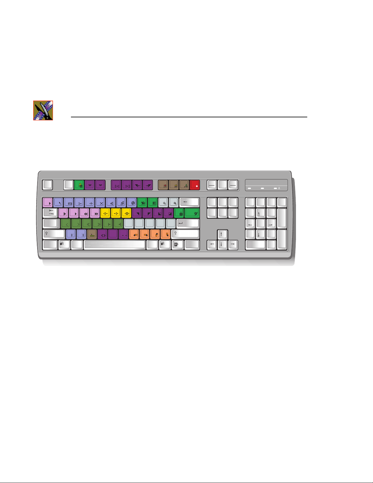
The Aurora Edit’s keyboard has color-coded keys that allow you to see editing
commands at a glance. Keys corre spo nd to Auror a Edi t functio ns. The Aurora
Edit system also includes a standard USB mouse.
Monitor
You can have one or two computer monitors attached to your Aurora Edit
workstation. In a dual-monitor configuration, one monitor usually displays
multiple bins, while the rest of the Aurora Edit appl ications displ ay on the other
monitor.
Print
Scrn
SysRq
_
+
-
0
{[}
"
J
V
M
O
L
A1KA2
<
,
:
A3
'
;
?
/>.
Backspace
=
|
]
\
Enter
A4
Shift
CtrlAlt Gr
Insert Home
Delete End
Pause
Scroll
Lock
Break
Page
Up
Page
Down
1A
Num
/*-
Lock
7
8
Home
465
2
1
End
0
Ins
9
Pg Up
3
Pg Dn
.
Del
+
Enter
Software
Aurora Edit software c onsists of t he Aurora Edit nonl inear editor in SD and HD
versions.
20 Aurora Edit Installation and Configuration Guide
Page 21
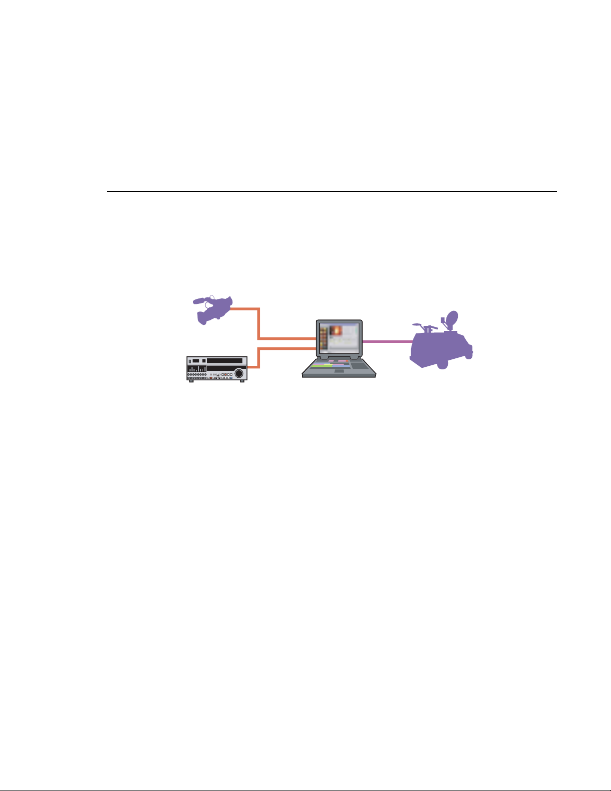
Aurora Edit LT
Aurora Edit LT
DV Camcorder
VTR
1394
Network
Card
Aurora LT
Mobile Uplink
Designed for field editing, the Aurora Edit LT system is a laptop computer with
DV25 video compression accomplishe d with software. It also includes a 1394
interface card and 100 GB of internal storage.
Aurora LT comes with a color-coded keyboard, letting you perform editing
functions quickly.
Aurora LT uses the Windows XP operating system.
Aurora Edit Installation and Configuration Guide 21
Page 22
Chapter 1 Introducing the Aurora Edit System
Comparing the Aurora Edit Products
This table shows how each of the Aurora Edit products, SD, HD, and LT
compare in their features:
Aurora Edit SD Aurora Edit HD Aurora Edit LT
Platform To wer or Rack Tower or Rack Laptop
Media Formats NTSC DV, DVCAM,
Media Formats PAL DV, DVCAM,
Max Data Rate 50 Mb/s + DV 100 Mb/s 50 Mb/s
Breakout Box Required Yes, SDR Yes, HDR No
Ethernet Workg roup Yes Yes Yes
K2 Storage Yes Yes Yes, via CIFS
GXF Transfer Support Yes Yes Yes
Color Correction and
2D Support
Titling Options Yes Yes Yes
Cuts and Transitions Yes Yes Yes
DVCPRO, MPEG, IMX
DVCPRO, MPEG, IMX
Yes Yes Yes
DV, DVCAM,
DVCPRO, MPEG, IMX
DV, DVCAM,
DVCPRO, MPEG, IMX
DV, DVCAM,
DVCPRO, MPEG
(playback only)
DV, DVCAM, DVCPRO
22 Aurora Edit Installation and Configuration Guide
Page 23

Other Components
There are several a dditional compone nts you may wish t o use with your Aur ora
Edit system:
• XRE Server, used for these services:
- SmartBin Servic e
- Domain Controller for Open SAN securit y
• Video Tape Recorder (VTR)—Allows you to use footage from video tapes.
• External monitor—Displays standard NTSC or PAL output.
• Audio mixer, such as Mackie 1402VLZPro—Allows greater control of
audio input.
• External controllers—The Jog/Shuttle Controller , Motorized Fader
Controller, and Effects Controller (available from Grass Valley) allow you
to control the Aurora Edit applicatio ns.
• Speakers.
Other Components
Aurora Edit Installation and Configuration Guide 23
Page 24

Chapter 1 Introducing the Aurora Edit System
Storage Options
With the Aurora Edit system, you have two options for storing files:
• Network Attached Storage (NAS) network, a shared storage network
consisting of these co mponents:
- NAS Server to manage the network file systems
- RAID arrays provide storage for all media
- Database System Manager (DSM), which hosts the Aurora database and
optionally the SmartBin Service
• K2 network, a shared storage network consisting of these components:
- K2 Media Server to manage the network file systems
- RAID arrays provide storage for all media
- Gigabit Ethernet Switch connecti ng the K2 Medi a Server and the Auro ra
Edit client devices
- Control point PC, which hosts the K2 Configuration application used to
configure the storage system
- Database System Manager (DSM), which hosts the Aurora database and
optionally the SmartBin Service
24 Aurora Edit Installation and Configuration Guide
Page 25
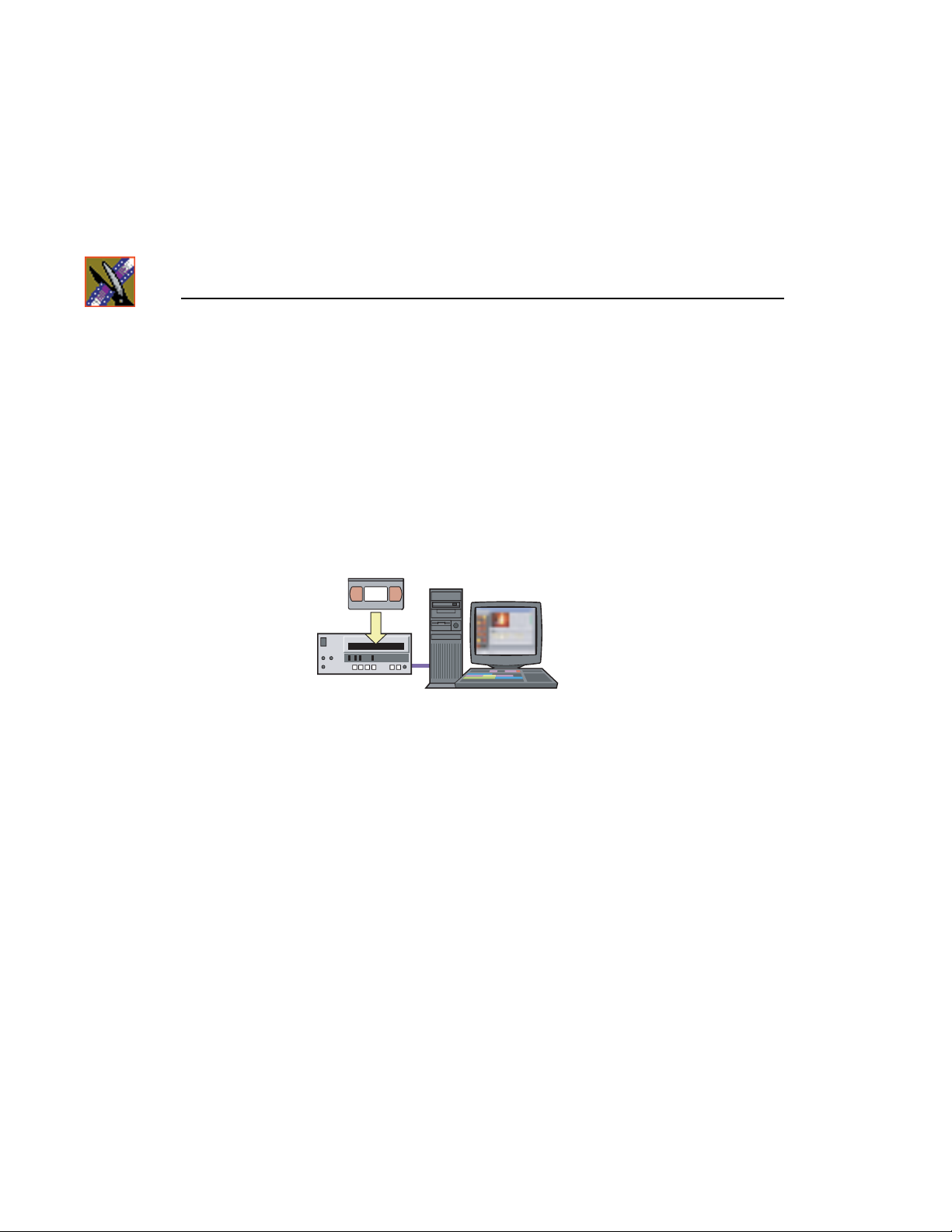
Digital News Production Workgroup Layout
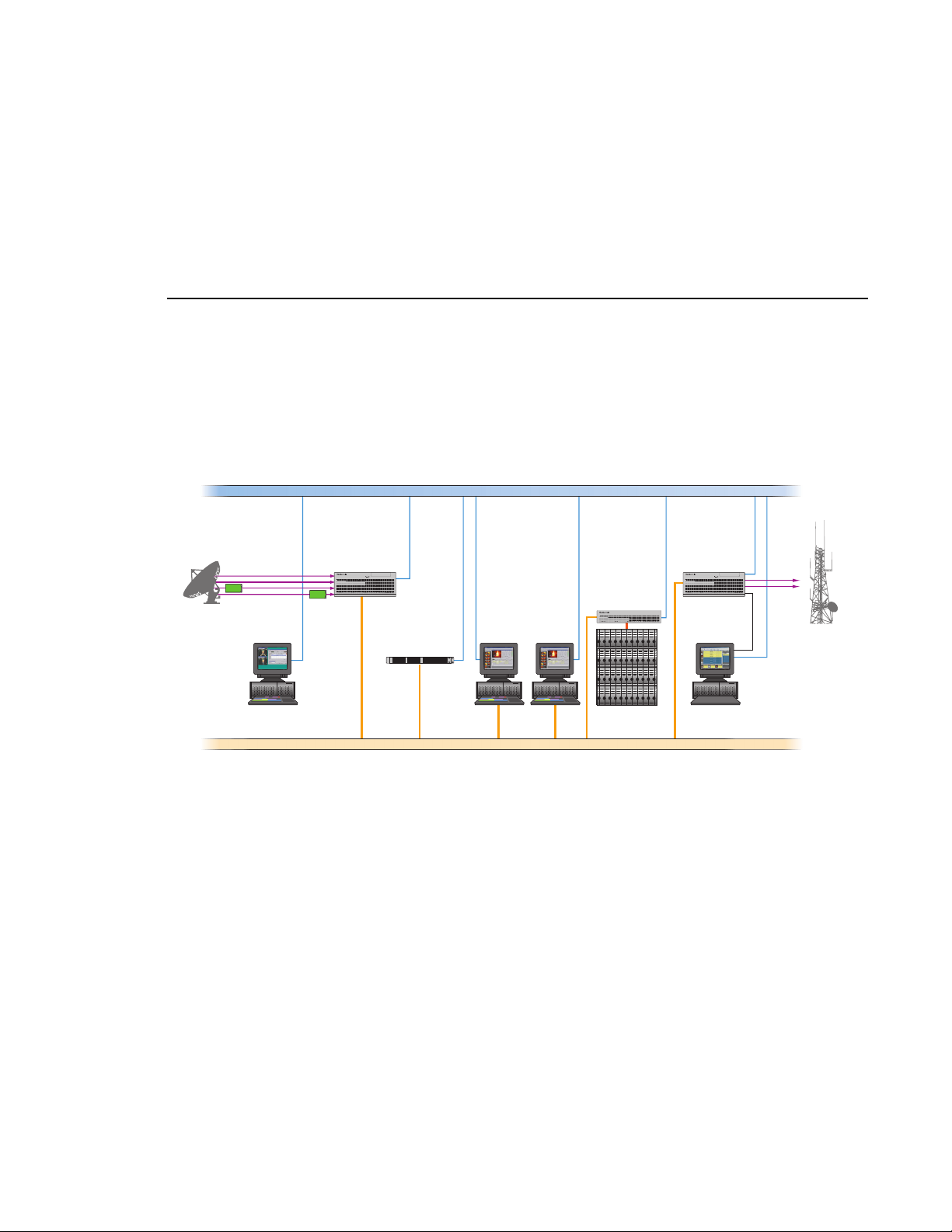
Digital News Production Workgroup Layout
This illustration shows a typical s etup for an Aurora Edit workstation withi n the
Digital News Production workgroup.
Ethernet Control LAN
Embedded SDI
incoming feeds
Aurora
Ingest
Ingest
K2 Media Client
! !
K2 Media Server
Aurora Edit
Aurora DSM
High Resolution Editing
Gigabit iSCSI network
K2 RAID
Shared Storage
Playout
K2 Media Client
Aurora
Playout
Aurora Edit Installation and Configuration Guide 25
Page 26

Chapter 1 Introducing the Aurora Edit System
26 Aurora Edit Installation and Configuration Guide
Page 27

Chapter
2
Setting Up the Hardware
Once you understand the site requirements and cabling guidelines, you can set
up your Aurora Edit workstation and connect the cables.
This chapter discusses:
• Site requirements
• Guidelines for cabling your Aurora Edit system
• Connecting system cables
• Connecting network cables
• Connecting a Video Tape Recorder
• Connecting audio and video to the Breakout Box
• Connecting an audio mixer
Aurora Edit Installation and Configuration Guide 27
Page 28
Chapter 2 Setting Up the Hardware
Site Requirements
This section details site requirements for your Aurora Edit system.
Power Requirements
It is highly recommende d that you use a surge protec tor and an uninte rrupt ible
power supply (UPS) with your system. There must be a 20 A, 110 to 120 V
alternating current, 60 Hz or 10 A, 220 to 224 V alternating current, 50 Hz
circuit breaker and an isolated ground.
Storage upgrades may require additional electrical service. Consider the
equipment nameplate ratings and consult your Thomson Grass Valley
representative.
The Aurora Edit system is designed to work with a single-phase (three-wire )
power cord with a grounded neutral conductor. To reduce the risk of electric
shock, always plug the cord into a powered off grounded power outlet.
For best performance, keep all system power connections on the same power
feed distribution pa nel . Do not co nnect a ny other equ ipment t o the sa me outle t
that is powering the Aur ora Edit equipment.
This table lists the power requirements for the system components.
Component Voltage Frequency Power
Aurora Edit Workstation 120/240 VAC 50/60 700 Watts
17" Monitor
(optional; spec based on Viewsonic A70)
Mackie 1402VLZ Pro (optional) 120/240 VAC 50/60 25 W
Fostex Speakers (optional) 120 VAC 5 W
Brocade Silkworm 2400 (optional 8 port) 100/240 VAC 50/60 1.5 Amps
Brocade Silkworm 2800 (optional 16 port) 10 0/240 VAC 5 0/60 1.5 Amps
Netgear FS516 Ethernet Switch
(optional 16 port)
28 Aurora Edit Installation and Configuration Guide
100/240 VAC 50/60 2 Amps
100/240 VAC 50/60 29 W
Page 29
Synchronization Re quirement s
You must have a stable video refe rence source to sync hronize the system i f you
are playing directly to air. The system needs no reference if the output is not
required to be genlocked.
Environmental Requirements
This table lists the specifications for a standard broadcast environment.
Condition Range
Operating temperature 50 to 75 degrees Fahrenheit
Storage tempe r ature 0 to 140 degr e e s Fah re nheit
Relative humidity 20% to 80%
Altitude 0 to 6000 ft. (0 to 1829 m)
Networking Requirements
Your system is designed to work over industry-standard local area networks
(LANs) and wide area networks (WANs) using standard TCP/IP networking
protocols. Insta ll all possibl e network cabling before t he equipment a rrives and
make note of the network IP addresses that reside within the network.
Synchronization Requirements
Fibre Channel
The Aurora Edit system transfers files to the playback server through a Fibre
Channel switch connection. Typically, fibre-optic cable is run along or inside
facilities ductwork using 62.5-micron termination connectors, SC type for the
Emulex Fibre Channel card and LC type for the Q-Logic Fibre Channel card.
Contact Thomson Grass Valley for sources for custom or off-the-shelf length
cables.
Ethernet Switch
The Ethernet switch routes data between all Aurora Edit systems, the playout
server, and newsroom systems. A 100-BaseT Ethernet switch is required to
connect network devices wi thin Aurora Edit product ion workgroups. A Gigabit
Ethernet switch is available and used for the Network Attached Storage
product. Status LEDs on the hub show network activity.
Aurora Edit Installation and Configuration Guide 29
Page 30
Chapter 2 Setting Up the Hardware
Cabling Guidelines
Creating a floor plan of your facilit y with user and equipment locations mar ked
will help you determine necessary cable lengths. Follow these guidelines to
install your Aurora Edit system:
• Use all cables delivered with your Aurora Edit system. All supplied cables
are tested and qualified for Thomson Grass Valley broadcast system
configurations.
• The monitors should be within 6 feet of the Aurora Edit workstation. You
may use VGA cable extensions, thoug h video images degrade with increas ed
length.
• The keyboard and mouse should be within 6 feet of the Aurora Edit
workstation. Use keyboard and mouse extensions only if necessary.
• The Breakout Box should be within 6 feet of the Aurora Edit workstation.
• The VTR should be within 15 feet of the Aurora Edit workstation for a
standard RS-422 length cable. An extension cable can be added for greater
distances.
• A fibre-channel switch should be within 1650 feet (500 meters) from the
Aurora Edit workstatio n when usin g a standard Multimode cable.
These cables ship with your Aurora Edit system:
Cable Description Length Connects
Standard power cords Up to 6 ft. (1.8m) All physical hardware with designated
Keyboard cable Up to 6 ft. (1.8m)
(Quality PS/2 extender
cables can be used)
Mouse cabl e Up to 6 ft. (1.8m)
(Quality PS/2 extender
cables can be used)
30 Aurora Edit Installation and Configuration Guide
power supply
Keyboard to Aurora Edit workstation
Mouse to Aurora Edit workstation
Page 31

You need to supply these cables for your Aurora Edit system:
Cable Description Length Connects
Cabling Guidelines
Fibre optic 62.5-micron, SC or LC
Multimode type, up to
1650 ft. (500m)
RJ-45 Cat5 Ethernet Customer desired Ethernet hub or switch to Aurora Edit
Remote serial Up to 15 ft. (4.6m)
(Quality RS422
extension modu le can be
used)
BNC video reference Customer desired Reference on Breakout Box
BNC video Customer desired Customer equipment to Breakout Box
XLR Audio Customer desired Customer supplied equipment to
Fibre channel switch to server fibre port
workstation ethernet port
Remote control from VTR to RS-422 card
on Aurora Edit workstation
Breakout Box
Aurora Edit Installation and Configuration Guide 31
Page 32

Chapter 2 Setting Up the Hardware
Connecting System Cables
This illustration shows a ty pical setup of how each of the components connect
to the Aurora Edit workstation. The following sections de scribe each
connection in detail.
Aurora Edit Monitor
32 Aurora Edit Installation and Configuration Guide
Page 33

Connecting the Keyboard and Mouse
To connect the keyboard and mouse:
1. Plug the keyboard cable in to the purple PS/2 por t (or USB port) on the back
of the Aurora Edit work station.
2. Plug the mouse cable into the green PS/2 port (or USB port) on the back of
the Aurora Edit workstation.
Connecting the Workstation Monitor
You can connect one or two workstation monitors to your system.
To connect a single monitor:
Connecting the Keyboard and Mouse
1. Plug the
cable into the monitor cable (for the primary monitor).
2. If necessary, plug the other end of t he monitor cabl e to the
the back of the monitor.
Some workstation monitors hav e the cable perman ently attach ed to the back
of the monitor.
3. Plug the monitor’s power cable into th e back of the monit or and into a power
strip or wall outlet.
To connect two workstation monitors to your system:
• Follow the instructions for the single monitor, but in addi tion, plug the
connector on the NVIDI A output adapter cabl e into the monit or cable for th e
second monitor.
VGA1 connector on the other end of the NVIDIA output adapter
Connecting the Power Cable
To connect the power cable:
• Plug the power cable from the back of the Aurora Edit workstation to a
power strip or wall outlet.
Connecting Network Cables
Depending on the type of network you have, and the type of storage system
you’ve chosen to use, you have different boards in your Aurora Edit system.
VIDEO IN port on
VGA2
Aurora Edit Installation and Configuration Guide 33
Page 34

Chapter 2 Setting Up the Hardware
Ethernet Connection
If you are using a Network Attached Storage (NAS) system, you are using a
Gigabit ethernet connection.
To connect an ethernet s witch to the A urora Edit workstation :
• Plug the end of the RJ45 cable in to the Gigabit port on the back of the Aurora
Edit workstation and the other end into your ethernet switch.
Fibre Channel Connection
If you are using a Profile Media Server as part of your Aurora Edit system, or
creating a shared sto rage system with an Open SAN network, you are using
fibre channel connections. You may have a single- or dual-port fibre channel
board.
To connect a fibre channel switch to the Aurora Edit workstation:
• Plug the ends of t he network cable i nto the
of the Aurora Edit workstation and the other ends into your fibre channel
switch.
TX and RX connectors on the back
34 Aurora Edit Installation and Configuration Guide
Page 35

Connecting a Video Tape Recorder
Connecting a Video Tape Recorder
In most situations, you con nect a VTR to your system to get foot age fr om tape.
To connect a VTR to your system:
1. Using a remote serial cable, plug one end into the top RS-422 port on the
back of the Aurora Edit workstation.
2. Plug the other end of the cable into the back of the VTR.
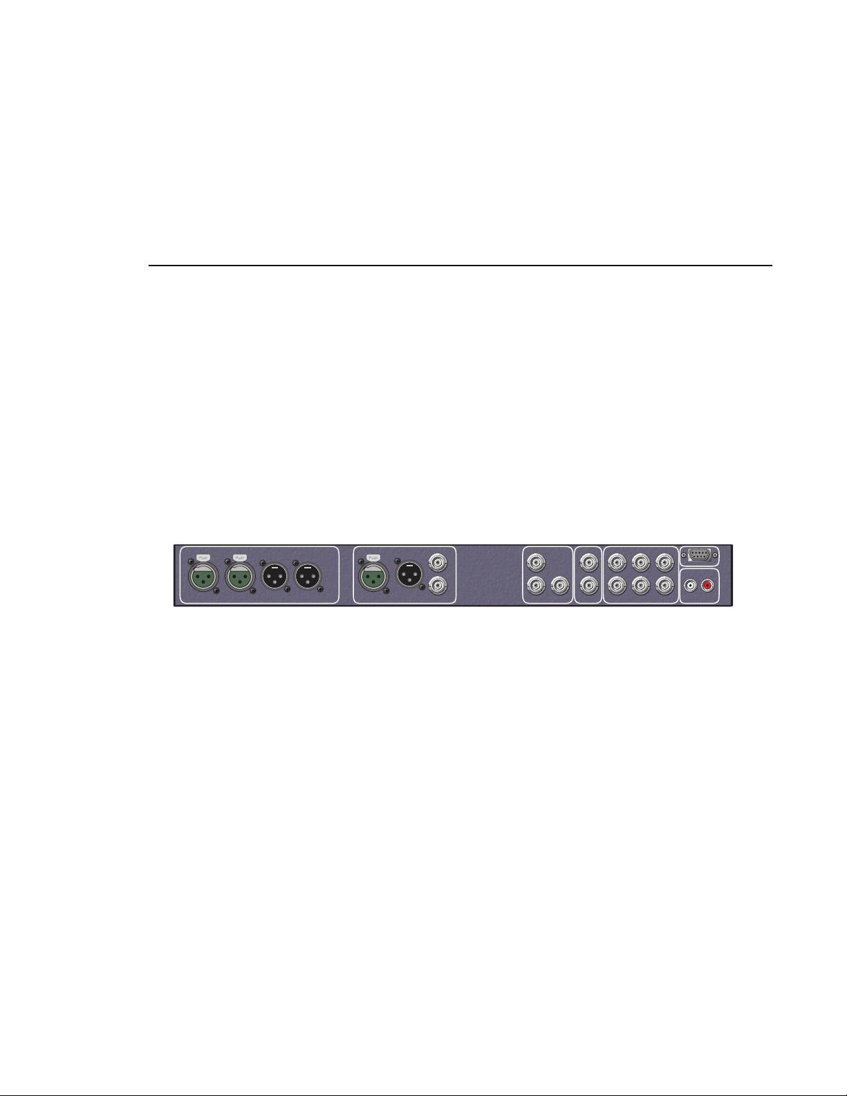
Connecting Audio and Video Cables to the Breakout Box
The following illustration and table details how to connect other video and
audio cables to your Aurora Edit system.
Balanced Audio IN
Channels 1 & 2
Ch. 1 In Ch. 1 OutCh. 2 In Ch. 2 Out
Balanced Audio OUT
Channels 1 & 2
BALANCED AUDIO
AES/EBU Audio
IN & OUT
AES/EBU
Ch. 1/2 In Ch. 1/2 Out
(loop)
Composite/
Component
Video IN
In
Out
Composite/
Component
Video OUT
Serial
Digital
IN
Audio
In
Out
Ch. 1/2
In
12
Out
SDI Ref Loop Y/CVBS Pb/Y Pr/C
Serial
External
Digital
Reference
OUT
In
Out
RS-422
Machine
Control
RS-422
Ch.1(L) Ch.2(R)
Analog Audio
Output
Aurora Edit Installation and Configuration Guide 35
Page 36

Chapter 2 Setting Up the Hardware
Input From To Cable type
Analog Audio
without a Mixer
Digital Audio VTR AES/EB U Chan nels
Video V TR-SDI Output Breakout Box SDI Inpu t Single BNC-B N C
VTR Channel 1 output Breakout Box balanced IN
VTR Channel 2 output Breakout Box balanced IN
Breakout Box Balanced
Left Out
Breakout Box Balanced
Right Out
Breakout Box Unbalanced
Left Out
Breakout Box Unbalanced
Right Out
1&2 Output
Breakout Box AES/EBU
Channels 1&2 Output
Breakout Box Unbalanced
Left Out
Breakout Box Unbalanced
Right Out
left channel
right channel
VTR Channel 1 input XLR-male to XLR-female
VTR Channel 2 input XLR-male to XLR-female
Left desktop speaker RCA-male to XLR-male or
Right desktop speaker RCA-male to XLR-male or
Breakout Box AES/EBU
Channels 1&2 Inp ut
VTR AES/EBU Channels
1&2 Input
Left desktop speaker RCA-male to XLR-male or
Right desktop speaker RCA-male to XLR-male or
XLR-female to XLR-male
XLR-female to XLR-male
1/4” male
1/4” male
XLR-male to XLR-male
XLR-male to XLR-female
1/4” male
1/4” male
Breakout Box SDI Output VTR SDI Input Single BNC-BNC
VTR Composite Output Breakout Box Composite
Breakout Box Composite
Output
VTR Component Output Breakout Box Component
Breakout Box Component
Output
Input
VTR Composite Input Single BNC-BNC
Input
VTR Component Output Tri BNC-BNC harness
Single BNC-BNC
Tri BNC-BNC harness
36 Aurora Edit Installation and Configuration Guide
Page 37

Connecting an Audio Mixer
Connecting an Audio Mixer
You can add an audio mixe r to e nhance Aurora’ s audi o capabi lit ies by feedi ng
multiple inputs into the editor. The following table is a suggested configuration
on the setup of a mixer and Aurora Edit, based on the Mackie 1402VLZPro.
Input From To Cable type
Analog Audio
with a Mixer
VTR Channel 1 output Mixer channel 1 line IN XLR-female to 1/4”-male
VTR Channel 2 output Mixer channel 2 line IN XLR-female to 1/4”-male
Main mixer out left channel Breakout Box balanced IN
Main mixer out right
channel
Breakout Box Balanced
Left Out
Breakout Box Balanced
Right Out
Breakout Box Unbalanced
Left Out
Breakout Box Unbalanced
Right Out
left channel
Breakout Box balanced IN
right channel
VTR Channel 1 input XLR-male to XLR-male
VTR Channel 2 input XLR-male to XLR-male
Left desktop speaker RCA-male to XLR-male or
Right desktop speaker RCA-male to XLR-male or
XLR-female to XLR-male
XLR-female to XLR-male
1/4” male
1/4” male
Aurora Edit Installation and Configuration Guide 37
Page 38

Chapter 2 Setting Up the Hardware
38 Aurora Edit Installation and Configuration Guide
Page 39

Chapter
3
Installing Aurora Edit Video Boards and Breakout Boxes (Optional)
If you want to use an external broadcast monitor to provide video output with
your Aurora Edit, you need to insta ll an SD R or HDR board and Breakou t Box.
These boards and Breakout Boxes provide a high-quality system for standard
and high definition video production workflows. The boards and Breakout
Boxes are available from Thomson Grass Valley.
This chapter discusses how to:
• Prepare the computer for board and Breakout Box Installation
• Install the SDR and HDR boards and Breakout Boxes
• Install the SDR and HDR drivers and control panels
• Enable SDI output on Aurora Edit SC
Aurora Edit Installation and Configuration Guide 39
Page 40

Chapter 3 Installing Aurora Edit Video Boards and Breakout Boxes (Optional)
SDR and HDR Board and Breakout Box Installation Procedure
Aurora Edit offers two 19” 1RU rack-mountable Breakout Boxes with
corresponding cards: SDR (standard definition) and HDR (high definition).
Both the SDR and HDR Breakout Box have the same front panel.
BALANCED AUDIO
Ch. 1 In Ch. 1 OutCh. 2 In Ch. 2 Out
AES/EBU
Ch. 1/2 In Ch. 1/2 Out
Audio
In
Out
Ch. 1/2
Using a Breakout Box and board requires that you have an Aurora Edit
workstation. Before in stallin g your boa rd and Break out Box, you must prepare
the workstation.
Preparing the Aurora Edit Workstation
To prepare the workstation for any box-board combination:
1. Power up the Aurora Edit workstation and, during the boot-up process,
access
2. Select
3. Enable the option:
4. Start Windows and click
The Control Panel window appears.
5. Double-click
The Local Security Settings window appear s.
BIOS setup (F10 key).
Advanced, then Thermal.
Full Speed Chassis Fans.
Start > Settings > Control Panel.
Administrative Tools > Local Security Policy.
In
12
Out
SDI Ref Loop Y/CVBS Pb/Y Pr/C
In
Out
RS-422
In
Out
Ch.1(L) Ch.2(R)
6. Click
Local Policies then double-click Security Options.
A list of security policy/setting options appears.
7. Scroll down to
accounts
Classic - local users authenticate as themselve s. Click OK.
40 Aurora Edit Installation and Configuration Guide
Network access: Sharing and security model for local
and double-click on it. Change the Network access setting to:
Page 41

Installing SDR and HDR Boards Into the Computer
Installing SDR and HDR Boards Into the Computer
The minimum software requirements for both boards is the Windows XP
Service Pack 2. The SDR and HDR boa rds in stall in th e compute r and con nect
to the Breakout Box. Both boards require the same computer installation
procedure. To install a board:
1. Disconnect power to your computer and remove the access panel.
2. Insert your SDR or HDR I/O board into Slot 6.
Note: For other slot/board functions, see “Connecting System
Cables” on page 32.
3. Replace the cover on the Aurora Edit computer.
Aurora Edit Installation and Configuration Guide 41
Page 42

Chapter 3 Installing Aurora Edit Video Boards and Breakout Boxes (Optional)
Cabling the SDR Board to the SDR Breakout Box
The SDR and HDR Breakout Bo x and thei r correspo nding car ds have di fferent
cable attachments. To connect an SDR board to an SDR Breakout Box:
1. Using the breakout cable provided with the Breakout Box:
a. Connect the 60-pin plug to the back of the Breakout Box; connect the
other cable end to the 60-pin plug in the board endplate.
b. Connect the three BNC cable connect ors to the back of the Brea kout Box;
connect the other cable end to the 9-pin D connector on the board
endplate.
.
BNC Connectors
Align slots in cable
Pin
Barrel
connector barrel with
connector pins.
Slide barrel over pins and
rotate barrel to lock
connectors together.
This device complies with Part 15 of FCC Rules. Operation is subject
SDI OUT 2
to the following two conditions: (1) this device may not cause harmful
interference and (2) this device must accept any interference received,
including interference that may cause undesired operation.
KBox
CONNECT TO HOST
SDI OUT 1
SDI IN
J1
The class A digital apparatus complies
with Canadian ICES-003. Cet appareil
numerique de la classe A est conforme
a la norme NMB-003 du Canada.
( (
42 Aurora Edit Installation and Configuration Guide
Page 43

Cabling the HDR Board to the HDR Breakout Box
The HDR and SDR Breakout Box an d their correspo nding car ds have diff erent
cable attachments.
To connect an HDR board to an HDR Breakout Box:
1. Using the connector cable provided with the Breakout Box:
a. Attach the 60-pin plug to the Breakout Box back panel.
b. Attach the other cable end to the 60-pin plug on the board endplate.
2. Using the three BNC connectors (labeled SDI IN, SDI OUT 1, and SDI
OUT 2):
a. Attach the plugs to the Breakout Box back panel.
b. Attach the other cable end to the BNC connectors on the board endplate.
Align slots in cable
connector barrel with
connector pins.
Slide barrel over pins and
rotate barrel to lock
connectors together.
Installing SDR and HDR Boards Into the Computer
BNC Connectors
Pin
Barrel
This device complies with Part 15 of FCC Rules. Operation is subject
KBox
CONNECT TO HOST
SDI IN
J1
to the following two conditions: (1) this device may not cause harmful
interference and (2) this device must accept any interference received,
SDI OUT 1
including interference that may cause undesired operation.
SDI OUT 2
The class A digital apparatus complies
with Canadian ICES-003. Cet appareil
numerique de la classe A est conforme
a la norme NMB-003 du Canada.
( (
SDI OUT 2
SDI OUT 1
SDI IN
Aurora Edit Installation and Configuration Guide 43
Page 44

Chapter 3 Installing Aurora Edit Video Boards and Breakout Boxes (Optional)
Installing the SDR or HDR Board Driver and Control Panel
Once you’ve installed the SDR or HDR board and connected the cables, you
need to inst all the boar d’s driver and control panel.
Installing the SDR or HDR Driver
The driver for the SDR or HDR board is located on the Auror a Edit CD, in the
Drivers | directory. You can use either the Found New Hard ware Wizard or the
Update Device Driver Wizard to install the driver.
44 Aurora Edit Installation and Configuration Guide
Page 45

Chapter
4
Connecting External Controllers to Aurora Edit
There are three external contr ollers you can us e with Aurora Edit : the Motorized
Fader Controller, the Jog/Shuttle Controller, and the Effects Controller.
This chapter discusses how to:
• Connec t each of the external controllers to an Aurora Edit workstation
• Assign a COM port to a particular controller
• Verify that the COM ports are configured correctly
Aurora Edit Installation and Configuration Guide 45
Page 46

Chapter 4 Connecting External Controllers to Aurora Edit
Introducing the External Controllers
An external controller lets you control features of Aurora Edit easily and
quickly.
Name of Controller Descri p tion
Jog/Shuttle Controls Aurora Edit externally, making
Motorized Fader Controls the audio features of Aurora E di t
Effects Controls creating and modifying effects in
editing faster. The controller incorporates a
jog/shuttle wheel for conve nient searching,
buttons to minimize keyboard strokes, and a
back-lit LCD timecode display for accurate
editing.
externally, making refining a nd perfecting the
audio mix of your sequences easi er. The
controller features four touch-sensitive,
motorized faders, 16 channel switches, 4
function keys, and bank shift buttons for
control of Aurora Edit audio functions.
Aurora Edit externally. The controller is a
3–axis joystick mechanism with five rotary
encoders and 10 switches for control of Aurora
Edit effect functions.
46 Aurora Edit Installation and Configuration Guide
Page 47

Connecting an External Controller to the Aurora Edit Workstation
Connecting an External Controller to the Aurora
Edit Workstation
You connect the controller to your Aurora Edit workstation using an RS-422
port for the Jog/Shuttle Controller and a USB port for the Fader or Effects
Controller.
The Aurora Edit workstation comes configured to use COM4 for the
Jog/Shuttle Controller.
Connecting the Jog/Shuttle Controller
1. Plug the controller’s 9-pin connector into the bottom RS-422 port on the
back of the Aurora Edit workstation (COM4).
2. Plug the controller’s power connector into a DC power adapter connection.
3. Verify that the following information appe ars on the controller’s display
when it powers up:
Grass Valley
Aurora Edit
Rev x.xx
4. Turn on your Aurora Edit workstation as usual.
Connecting the Motorized Fader or the Effects Controller
1. Plug the controlle r’s USB connector into one of the two ava ilable USB port s
on the back of your Aurora Edit workstation (usually COM5 for the
Motorized Fad er Controll er and COM6 fo r the Effects Controller).
2. If you are connecting the Motorized Fader Controller, plug the controller’s
power connector into a DC power adapter connection.
The Effects Controller is powered off the USB cable.
3. Turn on your Aurora Edit workstation as usual.
4. When the New Hardware Wizard appears, follow the directions on the
screen.
5. When asked for the co ntroller’s driver, navigate to:
Files\Vibrint 3.0\Drivers\JLC USB Drivers
6. Finish the new hardware installation.
Aurora Edit Installation and Configuration Guide 47
.
C:\Program
Page 48

Chapter 4 Connecting External Controllers to Aurora Edit
Verifying the COM Port
To verify tha t the COM port is set correctly in the Device Manager:
1. Right-click on My Computer and select
2. Click the Hardware tab on the System Properties window and click
Manager
3. Click the
4. Click on
.
+ symbol next to the Ports item.
JLCooper USB to Serial (COM#) and select Properties.
5. Click the Port Settings tab on the Properties tab and click
Properties.
Device
Advanced.
6. In the COM Port Numb er field, select the correct COM port f rom the pulldown list.
7. Click
8. Click
OK to close the Advanced window.
OK again to close the Properties window.
48 Aurora Edit Installation and Configuration Guide
Page 49

Assigning a COM Port for the Controller
Assigning a COM Port for the Controller
To use any of t he control lers, you need to ass ign a spec ific COM port in Aurora
Edit for the controller . Aurora Edit has pre-configured CO M ports as follows:
COM Port Type of Por t Configured Dev ice
1 GPIO Aurora Playout GPIO
2
3 RS-422 Video Tape Recorder (VTR)
4 RS-422 Jog/Shuttle Controller
5 USB Motorized Fader Controller
6 USB Effects Controller
To assign a COM port:
1. In Aurora Edit, choose
2. For the Jog/Shuttle Controller, select the correct COM port from the
Controller Comm Port
correct COM port from the
Tools | Options | Controller.
422
drop-down list; for the other controllers, select the
USB Controller Comm Port drop-down list.
The COM port needs to match the number of the USB port where you
connected the controller.
3. Click
OK.
You can now use the controller to control features on Aurora Edit.
Aurora Edit Installation and Configuration Guide 49
Page 50

Chapter 4 Connecting External Controllers to Aurora Edit
50 Aurora Edit Installation and Configuration Guide
Page 51

Chapter
5
Turning On the Aurora Edit Workstation
Once your workstation is cabled, you are ready to turn it on and launch the
Aurora Edit applications.
This chapter discusses:
• How to power up the system
• The System Self T est
• How to la unch Aurora Edit applications
Aurora Edit Installation and Configuration Guide 51
Page 52

Chapter 5 Turning On the Aurora Edit Workstation
Powering Up the System
You power up the Aurora Edit workstation by pushing the power button in on
the front pa nel.
52 Aurora Edit Installation and Configuration Guide
Page 53

Understanding the System Self-Test
Understanding the System Self-Test
The Aurora Edit workst ation runs a System Self-Test automatically each time
that you boot the workstation. The System Self Test looks at three areas:
• Software Installation—Checks for the correct version of Profile software,
Direct X driver, Targa drivers, operating system, video drivers, and export
and cache service.
• System Configuration—Checks for the correct version of Targa board,
Breakout Box firmware, audio renderer, and the VMR.
• AV Disk Performance—Tests the media drives input and output
performance.
As the System Self-Test runs, you see the results in the System Self-Test
window:
Aurora Edit Installation and Configuration Guide 53
Page 54

Chapter 5 Turning On the Aurora Edit Workstation
Each area tested can have one of three results:
This symbol... Means... Do this...
The test passed. Use your Aurora Edit workstation as usual.
The test is currently
running.
The test failed. See “Troubleshooting the System Self-Test”
Wait for the test to complete.
on page 55 for instructions.
If you are using shared storage, the AV Disk Performance Test is skipped and
you see this message: The AV Disk Test detected a shared volume - test skipped.
Running the System Self-Test Manually
You can run the System Self-Test anytime you want to test the system. Before
running the System Self-Test, make sure that the Aurora Edit program is not
running.
To run the System Self-Test:
•Go to
The Self-Test runs.
Programs | Startup | SystemSelfTest.
54 Aurora Edit Installation and Configuration Guide
Page 55

Troubleshooting the System Self-Test
On occasion, you may have a need to troubleshoot an error message from the
system self-test.
Troubleshooting the System Self-Test
Aurora Edit Installation and Configuration Guide 55
Page 56

Chapter 5 Turning On the Aurora Edit Workstation
If any of the three tests f ail, use this table to determine the c ause and fix the
problem.
If you see this message... It means...
Video card driver ___ is not supported.
CVFS client file system ___ is not supported.
DirectX driver version ___ is not supported.
Emulex LAN driver ___ is not approved.
Emulex SCSI driver ___ is not approved.
QLogic LAN driver ___ is not approved.
QLogic SCSI driver ___ is not approved.
No break out box detected.
Unsupported break out box detected.
Profile Errors:
Installed Profile software is version ___.
Profile software not found.
The approved version of the Profile software
is x.x.
The XX database server is not compatible.
You have an incorrect version of one of the drivers installed
on your system .
1. Insert the Aurora Edit CD into the CD-ROM drive
on the workstation.
2. Navigate to the Drivers directory.
3. Install the latest driver.
Contact your Customer Service Representative for further
details.
1. Check all cable connections from the Breakout Box
and to the Aurora Edit workstation.
2. Check that the power cable is connected correctly to
the Breakout Box.
The Profile software is either not installed on your
workstation or is not the current version.
1. Insert the Aurora Edit CD into the CD-ROM drive
on the workstation.
2. Navigate to the
version/XP
3. Double-click on the file
Software I nstalls/P rofile
directory.
Setup.exe.
4. Follow the instructions for “Installing the Aurora
Edit Software” on page 58.
The shared database is not compatib le with your v ersion of
Aurora Edit software.
On your FSM or DSM, run the
SetupAuroraShareServer
utility, which can be found on the Aurora Edit
CD-ROM.
For more information, see the NewsShare Technical
Reference Guide.
ERROR during AV Disk Test:
remote volume detected.
You are using shared storage. The AV Disk Performance
test checks the local media drives, so the test doesn’t run if
shared storage is used.
ERROR during AV Disk Test:
Your local disk drive is too slow; it needs to be <12 Mb
read/write.
56 Aurora Edit Installation and Configuration Guide
Page 57

Chapter
6
Installing Software
This chapter discusses how to:
• Install the Aurora Edit software
• Obtain a software license number
• Launch Aurora Edit applications
Aurora Edit Installation and Configuration Guide 57
Page 58

Chapter 6 Installing Software
Installing the Aurora Edit Software
The Aurora Edit softwa re should already be in stalled on your workstat ion when
your system arrives. If you ever need to install it, follow these instructions.
NOTE: If you have an old version of News Edit or Aurora Edit
software installed on your workstation, you fi rst need to uninstall it.
To uninstall software, go to your desktop and click Start>Control
Panel>Add or Remove Programs.
To install t he Aurora Ed it software:
1. Insert the Aurora Edit CD into your CD drive and navigate to
Installs | DNP Application
2. Double-click on
The Profile S oftware Not Detected Win dow appears :
3. Click
4. Follow the directions below for using Local or Shared Storage.
If your system is part of an Open SAN system or connected to Network
Attached Storage (NAS) or a K2 Server, use the instructions for Shared
Storage; otherwise, use the instructions for Local Storage.
OK.
The Profile Software loads automatically.
SetupAuroraEdit.exe.
.
Software
58 Aurora Edit Installation and Configuration Guide
Page 59

Local Storage System
Follow these instructions for installing the Aurora Edit software on a system
using local storage:
On this screen... Do this...
Welcome
Next.
Click
Local Storage System
License Agreement
Use the scroll bar on the right to scroll through and
read the agreement.
Click on the
Click
I Agree button.
Next.
Aurora Edit Installation and Configuration Guide 59
Page 60

Chapter 6 Installing Software
On this screen... Do this...
Select Destination Directory
Select Shared or Local Installation
Click Next to leave the destinat ion directory set at the
default location:
C:\Program Files\Grass Valley\Aurora Edit
NOTE: If you wish to change the default directory,
click Browse. Scroll through the pulldown list to the
desired directory , click on it to select it, then cl ick OK.
The change appears in the Select Destination
Directory window. Click Next to continue.
Click on the
Domain Security is used with shared systems. Leave
Local button to select it.
this box blank.
Next.
Click
60 Aurora Edit Installation and Configuration Guide
Page 61

On this screen... Do this...
Specify Directory for Local Video and Audio Files
Click Next to leave the destinat ion directory set at the
default location:
NOTE: If you wish to change the default directory,
click Browse. Scroll through the pulldown list to the
desired directory , click on it to select it, click OK. The
change appears in the Specify Directory for Local
Video and Audio Fi les window. Click Next to
continue.
Ready to Install
Local Storage System
D:\VibrintAVFiles
Click Next to begin the installation.
Aurora Edit Installation and Configuration Guide 61
Page 62

Chapter 6 Installing Software
On this screen... Do this...
System Self-Test
Aurora Edit installs the necessary drivers and sets up a
database to store your files. A System Self-Test
automatically runs and checks:
• Software Installation
• System Configuration
• AV Disk Performance
See “Underst anding the Syste m Self-T est” on page53
for troubleshooting and additional test information.
62 Aurora Edit Installation and Configuration Guide
Page 63

Shared Storage System
Follow these instructions when installing the Aurora Edit software on a system
using shared storage that is par t of an Open SAN syste m or connect ed to a K2
Server or Network Attached Storage (NAS):
On this screen... Do this...
Welcome
Shared Storage System
Next to continue.
Click
License Agreement
Use the scroll bar on the right to scroll through and
read the agreement.
Click on the
Click
I Agree button.
Next to continue.
Aurora Edit Installation and Configuration Guide 63
Page 64

Chapter 6 Installing Software
On this screen... Do this...
Select Destination Directory
Select Shared or Local Installation
Click
Next to leave the destination directory set at the
default location:
C:\Program Files\Grass Valley\Aurora Edit
NOTE: If you wish to change the default directory,
click Browse. Scroll through the pulldown list to the
desired directory , click on it to select it, click OK. The
change appears in the Select Destination Directory
window, click on it to select it, click OK. The change
appears in the Select Destination Directory. Click
Next to continue.
Click on the
Shared button.
To enable security (optional) on y our shared database ,
put a check in the
Domain Security box by clic king on
it.
NOTE: See “
Appendix C,
description of security features enabled by the
Security
Click
Setting Security Permissions” in
Configuring Aurora Edit for a
Domain
option.
Next to continue.
64 Aurora Edit Installation and Configuration Guide
Page 65

On this screen... Do this...
Specify the Servers for the Shared Database
Type the names of the primary and secondary (if
applicable) File System Managers (FSM) or Datab ase
System Managers (DSM) that will be used for the
shared database.
NOTE: Normally, for an open SAN, the names would
be FSMs; for a K2 or NAS system these would be
DSMs.
NOTE: If you are not using a secondary server, leave
Server 2 field blank.
the
Next to continue.
Click
Specify Directory for Shared Video and Audio Files
Shared Storage System
Click
Next to leave the destination directory set at the
default location:
V:\VibrintAVFiles
NOTE: If you wish to change the default directory,
click Browse. Scroll through the pulldown list to the
desired directory and double-click on it. Click Next to
continue
Aurora Edit Installation and Configuration Guide 65
Page 66

Chapter 6 Installing Software
On this screen... Do this...
Specify Directory for AV Cache Files
Specify Directory for Local Video and Au dio Files
Next to leave the destination directory set at the
Click
default location:
D:\VibrintAVCache
NOTE: If you wish to change the default directory,
click Browse. Scroll through the pulldown list to the
desired directory , click on it to select it, click OK. The
change appears in the Specify Directory for AV Cache
Files window. Click Next to continue.
Click Next to leave the destination direct ory set at the
default location:
D:\VibrintAVFiles
NOTE: If you wish to change the default directory,
click Browse. Scroll through the pulldown list to the
desired directory , click on it to select it, click OK. The
change appears in the Specify for Local Video and
Audio Files window. Click Next to continue.
66 Aurora Edit Installation and Configuration Guide
Page 67

On this screen... Do this...
Specify the Shared Drive(s) in Use with this System
Enter the drive letter(s) of the drive(s) used on the
shared system. Separate multiple drives with commas
(e.g., V,W,X).
NOTE: See your system administrator for the drive
letter(s) on your system; the default drive letter is
Next to continue.
Click
Ready to Install
Shared Storage System
V.
Click Next to begin the installation.
Note: If the DiskVol umeConfig window appea rs, see “Configuring the Disk Volume” on page 69
for instructions.
Aurora Edit Installation and Configuration Guide 67
Page 68

Chapter 6 Installing Software
On this screen... Do this...
System Self-Test
Aurora Edit installs the necessary drivers and sets up a
database to store your files. A System Self-Test
automatically runs and checks:
• Software Installation
• System Configuration
• AV Disk Performance
See “Underst anding the Syste m Self-T est” on page53
for troubleshooting and additional test information.
Click Close.
68 Aurora Edit Installation and Configuration Guide
Page 69

Configuring the Disk Volume
When you install Aurora Edit 6.0 software for the first time, the Disk Volume
Configuration window appears during the process. You need to configure the
shared volume for your type of network and equipment. The Disk Volume
Configuration only needs to be done once on each shared volume, on the first
Aurora Edit system installing the 6.0 version of software.
Configuring the Disk Volume
To configure the disk volume:
1. Select the disk volume drive letter and configure the volume as follows:
Setting Options Description
Disk Volume Type
Disk Volume Model
Aurora Edit Installation and Configuration Guide 69
Unknown
LocalDisk
Open SAN
NAS
K2 Storage
Unknown
Grass Valley PFR500,
PFR600, PFR700, PFR800
Ciprico 1700, 2400, 3600
IBM NAS
Select your type of shared storage.
Open SAN:
Choose Grass Valley PFR500, PFR600, PFR700, or
PFR800; if you don’t know, select PFR600.
NAS:
Choose Ciprico 1700, 2400, 3600, or IBM NAS.
K2 Storage:
Grass Valley PFR700.
Choose
Page 70

Chapter 6 Installing Software
Setting Options Description
Security Options
2. Click OK to save changes and return to the software installer.
Supported
Not Supported
Select Supported if your system is configured to use
Domain Security; if not, select Not Supported.
70 Aurora Edit Installation and Configuration Guide
Page 71

Obtaining a Software License Number
Obtaining a Software License Number
Once you’ve installed the Aurora Edit software, you need to get a License
Number from Grass Valley.
To obtain a license, first doub le-click the Aurora License Reques t icon on your
desktop, th en fill in the following sc reen informa tion:
On this screen... Do this...
Welcome
Read the on-screen instructions.
Next to continue.
Click
Customer
Enter your name, email, and company into the
required fields.
Filling in the address, country, a nd phone fields is
optional.
Next to continue.
Click
Aurora Edit Installation and Configuration Guide 71
Page 72

Chapter 6 Installing Software
On this screen... Do this...
Sales Number
Summary
Enter the Sales Order number located on the Aurora
License Document provided by Grass Valley.
Click Next to continue.
Check to make sure the correct information was
entered.
Click Finish.
This creates a file on your desktop called:
License_Request_demo.txt
Attach this file to an email and send to:
AuroraLicenses@thomson.net
72 Aurora Edit Installation and Configuration Guide
Page 73

Launching Aurora Edit Applications
Launching Aurora Edit Appli catio ns
To launch applications from your local hard drive:
• Double-click the application icon on the workstation desktop or open the
program by clicking
Start | Programs | Vibrint | <name of program>.
Aurora Edit Installation and Configuration Guide 73
Page 74

Chapter 6 Installing Software
74 Aurora Edit Installation and Configuration Guide
Page 75

Chapter
7
SmartBins
This chapter covers:
• Understanding SmartBins
• Transfer SmartBins
• Shared SmartBins
• Media Import SmartB ins
and how to install the s oftware, configu re the system, o btain a lice nse and setup
a SmartBin o n Aurora Edit for each type of SmartBin.
Aurora Edit Installation and Configuration Guide 75
Page 76

Chapter 7 SmartBins
Understanding SmartBins
SmartBins provide a way to automatically synchronize media access between
Aurora Edit and media server bins. A SmartBin is an Aurora Edit bin that
monitors a folder on a media server and automatically updates the SmartBin
contents when new or updated media appears.
Updating the Databases
A SmartBin s Service constantly mo nitors bot h the Aurora E dit and media
server databases. Examples of updates to the database are listed below.
Action Media Server Database Aurora Edit Database
Rename
clip
Delete
clip
Delete
bin
Add a
movie
Create
master
clip
on media
server
on Aurora
Edit
on media
server
on Aurora
Edit
on media
server
on Aurora
Edit
on media
server
on Aurora
Edit
Clip renamed. SmartBins service renames clip; if clip
Clip renamed per Aurora Edit unless
there is a conflict, in which case
renaming fails in both databases.
Clip deleted. SmartBins service deletes clip; if the
Clip deleted per Aurora Edit unless
there is a conflict, in which case
deletion fails in both databases.
Bin (and all movies contained within) deleted, unless a clip is being used in
Aurora Edit in which case the deletion fails in both databases.
No change; bin not deleted. SmartBin monitoring disabled; bin and
Movie added. SmartBins service registers clip unless
SmartBins service registers master clip
when recording is complete.
cannot be renamed, the databases
become out-of-sync.
Clip renamed unless there is a conflict
on the media server, in which case
renaming fails in both databases.
clip is in use, databases become out-ofsync.
Clip deleted unless there is a conf l ict
on the media server, in which case
deletion fails in both databases.
bin contents deleted.
it is a complex movie, in which case
the clip is not registered and the
databases become out-of-sync.
Master clip created while recording
76 Aurora Edit Installation and Configuration Guide
Page 77

NOTE: The Aurora Browse system includes a component called the
SmartBin Encoder, which is different from a Media SmartBin or a
Server SmartBin because it monitors bins for the creation of lowresolution proxy mater ial. The S martBin Encod er is in stall ed on the
Aurora Browse Advanced Encoder.
Types of SmartBins
The Aurora Edit system offers three types of SmartBins:
•Transfer
•Shared
• Media Import
SmartBins work differently depending on the type of shared storage network
you are using: Open SAN, NAS, or K2.
Types of SmartBins
Aurora Edit Installation and Configuration Guide 77
Page 78

Chapter 7 SmartBins
Transfer SmartBins
Transfer SmartBins set up automatic clip transfers from a media server to an
Aurora Edit Bin. Transfer SmartBins handl e clips from a Profile, an M-Series
iVDR, or a K2 media server.
On an Aurora Share NAS or K2 System, Transfer SmartBins map folders from
a bin in the Aurora Edit tree view to a bin in the media server view. Media is
transferred, uni-directionally, via GXF from the media server to the Aurora Edit
Bin and registered in the Aurora Share database so it can be seen from Aurora
Edit.
Transfer SmartBins use a static directory mapping so all files in a particular
media server bin are monitored and automatically transferred as they arrive to
a selected Aurora Edit Bin, and are then (optionally) deleted from the media
server.
Transfer SmartBins effectively create a buf fered recor ding so that m aterial is
protected and redundantly saved (both on the media server and on the NAS or
K2 storage) while still making the file available for shared editing or immediate
playout. There is a 30-second delay before the reco rded material is ava ilable on
Aurora Edit.
Transfer SmartBins on a NAS or a K2 system require an external XRE Server
or DSM to provide the folder monitoring and transfer services to the NAS
system. A DSM can support up to 4 25-Mbit record str eams (2 M-Seri es iVDR
chassis). Beyond four streams, dedicated XRE Server s should be used as
necessary, budgeting 6 streams per XRE Server. You also need to mount the
NAS or iSCSI volume on the workstation running the SmartBins Service.
Setting up Transfer SmartBins requires four steps:
1. Mount drives.
2. Install SmartBins software.
• Install the SmartBins S ervice
• Run the SmartBins Setup Tool.
• Verify DCOM configuration.
3. Obtain a software license.
4. Create a Transfer SmartBin on Aurora Edit
These steps are discussed below.
78 Aurora Edit Installation and Configuration Guide
Page 79

Step 1: Mount the NAS Volume for Transfer SmartBins
Step 1: Mount the NAS Volume for Transfer SmartBins
If you are using Transfer SmartBins on a NAS system, you need to mount the
NAS volume on the device running t he SmartBins Servi ce before instal ling the
Aurora Edit software.
To mount a NAS volume:
1. On the device you want to map the drive to, open
Tools | Map Network Drive
.
2. Select the NAS drive letter from the drop-down list.
3. Type in the name of the NAS folder where the shared database resides.
4. Check the
Reconnect at logon checkbox.
My Computer and select
5. Click
Finish.
Step 2: Install the Software for Transfer SmartBins
In order to use Transfer Smar tBi ns, you must install client soft war e. If usi ng a
K2 system, install the G VG_Mlib c lient software; if using a SAN system,
install the Profile client software. The software must be installed on the system
hosting the SmartBin Server , whic h may be a DSM or a se par at e XRE Serve r.
Aurora Edit Installation and Configuration Guide 79
Page 80

Chapter 7 SmartBins
On this screen... Do this...
Welcome Click Next.
Setup Type
Ready to Install
l
K2_Server1
Enter the name of the K2 server.
If you have a back-up server, enter
that name as well; otherwise, leave
the second entry space blank.
Next.
Click
To review or change your settings,
Back.
click
To begin the installation process,
Install.
click
Installation Complete Click
Finish. If this is an initial
installation, the workstation
prompts you to reboot.
80 Aurora Edit Installation and Configuration Guide
Page 81

Step 2: Install the Software for Transfer SmartBins
Install the SmartBins Service for Transfer SmartBins
Following the client software installation, the SmartBins Service must be
installed.
To install the SmartBins Service:
1. Insert the Aurora Edit CD into your CD drive and navigate to the
Service
2. Double-click on
folder.
SetupSmartBinsService.exe.
SmartBins
3. Follow these instructions:
On this screen... D o this...
Welcome Click Next.
Select Destination Directory Leave set at the default location and click
Select SmartBin Option 1. Select SmartBins Encod er if you are
K2 Server Check If a K2 Server is not present, clear the check mark in
Specify the Servers for the Shared
Database
installing this software on an Aurora Browse
SmartBin Encoder; otherwise, select
Standard.
NOTE: Selecting
installs the Aurora FTP Service. See Chapter 8,
“Installing the Aurora FTP Service,” for details.
2. If you want to us e security on your shared
volume, check
3. Click Next.
the indicator box.Click
Enter the names of the primary and secondar y (if
applicable) Database System Managers. Click Next.
SmartBins Encoder also
Domain Security.
Next.
Next.
Specify Directory for Shared Video
and Audio Files (Standard option
only)
Specify Directory for AV Cache
files
Specify the shared drive(s) for use
with the shared storage
Ready to Install Click
Leave set at the default loca tion and click
Leave set at the default loca tion and click
Leave set at the default loca tion and click Next.
Next to begin the installation.
Next.
Next.
Aurora Edit Installation and Configuration Guide 81
Page 82

Chapter 7 SmartBins
On this screen... D o this...
Installation Complete Click OK to close the installation program. The
workstation prompts you to reboot so the new
settings take effect.
Run the SmartBins Setup Tool for Transfer SmartBins
If you are using Smar tBins on a NAS or K2 system, you need to confi gure your
M-Series iVDR(s), Profile XP, or K2 Media Server to use SmartBins.
NOTE: You don’t need to configure SmartBins on an Open SAN
system.
To configure the SmartBins Service on a NAS or K2 system:
1. Go to
Start | Programs | Aurora 6.0 | SmartBins Setup Tool.
The SmartBins Setup Tool opens.
2. Select the
Total Maximum Transfers from the drop-down list.
The Total Maximum Transfers is the total amount of streams for this particular
instance of the SmartBins Service. Select
82 Aurora Edit Installation and Configuration Guide
4 if the SmartBins Servic e is installe d
Page 83

Step 2: Install the Software for Transfer SmartBins
on the DSM and select 6 if the SmartBins Se rvice is installed on a st andalone
PC.
NOTE: Increasing the number of Total Maximum Transfe rs affects
the bandwidth on the NAS system.
3. Click
Add.
The Edit Server Settings window appears:
4. Enter the name of the Profile Server, M-Series iVDR, or K2 Media Client
you are using.
5. Select the number of
Maximum Transfers per server from the drop-down
list.
If you are installing thi s software on a DSM, the maximum numbe r of transfers
is 4.
6. Check
Delete movies after __ hours, and enter the number of ho urs after a
transfer is complete for media to remain in the database before being
automatically removed from the video server, not the Aurora Edit.
7. Click
OK to close the setup tool.
The SmartBins Service restarts.
Aurora Edit Installation and Configuration Guide 83
Page 84

Chapter 7 SmartBins
Verify the DCOM Configuration on Your System
DCOM is the Microsoft Distributed Component Object Model that allows
software to communicate over a network in a secure and r eliable way. If DCOM
permissions are not setup correctly on your system, network communications
may not work properly. To verify tha t it is conf igure d as requir ed, perform the
following steps:
1. Click the
2. Type
Start icon on your computer’s toolbar and choose Run.
Dcomcnfg.exe and click OK
3. Click Component Services under the Console Root
4. Open the
5. Right-click
6. Click the
7. Look at the
8. Select
Computers folder.
My Computer and then Properties.
COM Security tab.
Access Permissions section. Click the Edit Limits box.
ANONYMOUS LOGON. It should have a check mark in the Remote
box .
• If there is not a check mark present, click the box.
9. Select
Everyone. It should have a check mark in the Remote box .
• If there is already a check mark, you are done. Exit Dcomcnfg.exe.
• If there is not a check mark present, click the box. If you clicked the
box and the check mark appeared, click
OK to apply the cha nges and
exit Dcomcnfg.exe. You must now reboot.
Step 3: Obtain a Software License Number for Transfer SmartBins
Once you’ve installed the SmartBins Service software, you need to get a
License Number from Grass Valley.
To obtain a License Number:
1. Double-click the License Manager icon on your desktop.
The Sabre Tooth License Manager Window opens:
84 Aurora Edit Installation and Configuration Guide
Page 85

Step 4: Create a Transfer SmartBin in Aurora Edit
2. Click File and choose Generate Unique ID ID from the drop-down menu.
The Unique ID Window opens with the new ID license number:
Call Grass Valley Product Support at 1-800-547-8949.
Step 4: Create a Transfer SmartBin in Aurora Edit
Once you’ve instal led the SmartBins Serv ice, you can create SmartBins that get
automatically monito red and updated. A SmartBin monitors the server folder
you specify and updates the content of the SmartBin automatically when new
clips or updated feeds appear. You don’t need to go into the server bin and copy
the media into your Aurora Edit bin in order to use it for editing
To create a Transfer SmartBin:
Aurora Edit Installation and Configuration Guide 85
Page 86

Chapter 7 SmartBins
1. Open Aurora Edit on any client workstation.
2. Click the
New Bin button on the Bin toolbar.
3. Select the SmartBin Type from the drop-down list:
Transfer SmartBin Sets up automatic clip transferring from a Media Server to an
Shared SmartBin Sets up folder mapping between a Media Server and a bin in
Media Import SmartBin Sets up automatic QuickTime DV25 .mov and DV50 .mov file
4. Click
Browse to the right of the Server Path field.
Aurora Edit Bin.
Aurora Edit.
imports into an Aurora Edit Bin.
The Select Server Bin window appears:
86 Aurora Edit Installation and Configuration Guide
Page 87

Step 4: Create a Transfer SmartBin in Aurora Edit
5. Enter the name of the server and click Connect (If you have an Open SAN
system, you don’t need to enter the name of the server).
NOTE: You only need to enter the n ame of the server the first time
you connect; the server connects automatically once you’ve set it up.
6. Select the bin to monitor and click
7. Click
OK to create the SmartBin.
OK.
Aurora Edit now monitors the Medi a Serve r folde r and adds new media t o this
bin automatically.
Aurora Edit Installation and Configuration Guide 87
Page 88

Chapter 7 SmartBins
Shared SmartBins
Shared SmartBins allow the Aurora Edit bin to monitor a folder o n a media
server. Media is not moved between the server and bin; instead, media is
mapped into the two directory structures — a process known as "winking".
Shared SmartBins handle media from Profile Open SAN and K2 SAN media
servers.
Shared SmartBins on an Open SAN or K2 SAN System
On an Open SAN or K2 SAN sy stem, SmartBi ns map folde rs fr om a bi n in the
Aurora Edit tree view to a bin i n the K2 view. As wi th drag and drop via Media
Manager, this automatic synchr onization never moves actu al media fi le s—t he
bin structure represents two different views into the shared media file system.
When you first create a bin in Aurora Edit, you can map that bin to a K2 bin;
after an Aurora Edit bin is create d, it cannot be mapped. Once an a ssociati on is
created, the Aurora Edit and K2 bins are kept synchronized.
SmartBins support simple ( flattened) movies, but not seq uences, sub-folders , or
sub-clips that the K2 cannot use directly. Also, SmartBins cannot have subbins.
The workstation running the SmartBins SAN service mus t have a Fibre
Channel-SCSI connection to the Open SAN and a CVFS or SNFS license.
Shared SmartBin Folder Synchronization
When the SmartBins Service starts, it determines which Aurora Edit bins are
associated with media server bins and then queries the media server database
for the movies in each associated bin. Any movies in media server bins that are
not in the associ ated Aurora Ed it bin are regi stered to t he Aurora Edit database.
The SmartB ins service does not verify that Auro ra Edit clip s are in the media
server database, so the synchronization is one way only—media server to
Aurora Edit .
No files are moved—a mapping of the folders between the flat and tree views
takes place.
Setting up Shared SmartBins requires three steps:
1. Mount the drives:
• For Open SAN, install CVFS.
• For K2 SAN install:
88 Aurora Edit Installation and Configuration Guide
Page 89

Step 1: Mount the drives for Shared SmartBins
-SNFS
- Generic iSCSI
- GVG_MLib
2. Install SmartBins Software.
• Install the SmartBins Servic e.
• Run the SmartBins Setup Tool.
3. Create a Shared SmartBin on Aurora Edit
NOTE: No software license is required for Shared SmartBins.
Step 1: Mount the drives for Shared SmartBins
To install the following software, you need your Profile or K2 software CD.
• For Open SAN, install CVFS.
• For K2 SAN install:
-SNFS
- Generic iSCSI
- GVG_MLib
Step 2: Install the Software for a Shared SmartBins
In order to use Shared SmartBins, you must install client software. If using a K2
system, ins tall the GVG_MLib client software; if using a SAN system, install
the Profile client software. The software must be installed on the system hosting
the SmartBin Server, which may be a DSM or a separate XRE Server.
Install GVG_MLib Software (for a K2 System)
You need to install GVG_MLib software on the workstation that will be
running the SmartBins Service on a K2 system.
To install the GVG_MLib software:
1. Insert the Aurora Edit CD into your CD drive.
Aurora Edit Installation and Configuration Guide 89
Page 90

Chapter 7 SmartBins
2. Navigate to Software Installs | GV_MLib.
3. Double-click on
Setup.exe.
Install the software follo wi ng the se ins tr uct ions:
On this screen... Do this...
Welcome Click Next.
Setup Type
K2_Server1
Ready to Install
l
Enter the name of the K2 server.
If you have a back-up server, enter
that name as well; otherwise, leave
the second entry space blank.
Next.
Click
To review or change your settings,
Back.
click
To begin the installation process,
click Install.
90 Aurora Edit Installation and Configuration Guide
Page 91

Step 2: Install the Software for a Shared SmartBins
On this screen... Do this...
Installation Complete Click Finish. The workstation
prompts you to reboo t so the new
settings take effect.
Install Profile Software (for an Open SAN System)
You need to inst all Profi le so ftwar e on t he workst atio n that will be runn ing t he
Shared SmartBins Service.
To install P rofile software:
1. Insert the Aurora Edit CD into your CD drive.
2. Navigate to
3. Double-click on
4. Install the software follo wi ng the se ins tr uct ions:
On this screen... Do this...
Welcome Click Next.
License Agreement Read and accept, then click
Setup Type
Software Installs | Profile.
Setup.exe.
Next.
Open SAN PC.
Select
Next.
Click
Ready to Install Click Install.
Aurora Edit Installation and Configuration Guide 91
Page 92

Chapter 7 SmartBins
On this screen... Do this...
Installation Complete Click Finish. If this is the
initial installation, the
workstation prompts you to
reboot so the new settings take
effect.
Install the SmartBins Service for Shared SmartBins
To install the SmartBins Service:
1. Insert the Aurora Edit CD into your CD drive and navigate to the
Service
2. Double-click on
3. Follow these instructions:
folder.
SetupSmartBinsService.exe.
On this screen... D o this...
Welcome Click Next.
Select Destination Directory Leave set at the default location and click
Select SmartBin Option 1. Select
2. If you want to us e security on your shared
3. Click Next.
SmartBins Encoder if you are
installing this software on an Aurora Browse
SmartBin Encoder; otherwise, select
Standard.
NOTE: Selecting
installs the Aurora FTP Service. See Chapter 8,
“Installing the Aurora FTP Service,” for details.
volume, check Domain Security.
SmartBins Encoder also
SmartBins
Next.
Specify the Servers for the Shared
Database
Specify Directory for Shared Video
and Audio Files (Standard option
only)
Specify Directory for AV Cache
files
Enter the names of the primary and secondar y (if
applicable) Database System Managers. Click
Leave set at the default location and click
Leave set at the default location and click
Next.
Next.
Next.
92 Aurora Edit Installation and Configuration Guide
Page 93

Step 2: Install the Software for a Shared SmartBins
On this screen... D o this...
Specify the shared drive(s) for use
with the shared storage
Ready to Install Click
Installation Complete Click OK to close the installation program. The
Leave set at the default loca tion and click Next.
Next to begin the installation.
workstation prompts you to reboot so the new
settings take effect.
Run the SmartBins Setup Tool for Shared SmartBins
If you are using Smar tBins on a NAS or K2 system, you nee d to configur e your
M-Series iVDR(s), Profile XP, or K2 Media Server to use SmartBins.
NOTE: You don’t need to configure SmartBins on an Open SAN
system.
To configure the SmartBins Service on a NAS or K2 system:
1. Go to
Start | Programs | Aurora 6.0 | SmartBins Setup Tool.
The SmartBins Setup Tool opens.
Aurora Edit Installation and Configuration Guide 93
Page 94

Chapter 7 SmartBins
2. Deselect the Transfer SmartBins and Media Import SmartBins, unless you
are also using those. Ensure the
Shared SmartBins box is check-marked.
3. Click
OK to close the setup tool.
The SmartBins Service restarts.
NOTE: No software license is required for Sh ared SmartB ins.
Step 3: Create Shared SmartBins in Aurora Edit
Once you’ve instal led the SmartBins Servic e, you can create SmartBins that get
automatically monitored and updated. A SmartBin monitors the server folder
you specify and updates the content of the SmartBin automatically when new
clips or updated feeds appear. You don’t need to go into the server bin and copy
the media into your Aurora Edit bin in order to use it for editing.
To create a SmartBin:
1. Open Aurora Edit on any client workstation.
2. Click the
3. Select the SmartBin Type from the drop-down list:
Transfer SmartBin Sets up automatic clip transferring from a Media Server to an
Shared SmartBin Sets up folder mapping between a Media Server and a bin in
New Bin button on the Bin toolbar.
Aurora Edit Bin.
Aurora Edit.
Media Import SmartBin Sets up automatic QuickTime DV25 .mov and DV50 .mov file
4. Click
Browse to the right of the Server Path field.
imports into an Aurora Edit Bin.
5. The Select Server Bin window appears:
6. Select the bin to map with and click
7. Click
OK to create the SmartBin.
OK.
Once the mapping associati on is made, the SmartBin Service automatically
keeps the bins synchronized.
94 Aurora Edit Installation and Configuration Guide
Page 95

Media Import SmartBins
Media Import SmartBins facilitate th e automatic import of Qui ckTime DV25
and DV50 .mov files into Aurora Edi t. This allows you to use Appl e’s Final Cut
Pro video editing application, within a NAS environment, to create news or
sports footage and then import it into Aurora Edit. Media Import SmartBins
work with MOV import for Final Cut Pro (FCP).
You can only have one Medi a Import Smar tBin serv er active a t any given time.
Setting up Media Import SmartBins requires four major steps:
1. Map the network drive to the MOV source directory.
2. Install SmartBin s software.
• Install the Smar tBins Service.
• Run the SmartBins Setup Tool.
3. Obtain a software license for Media Import Sma rtBins.
4. Create a Media Import SmartBin on Aurora Edit.
These steps are discussed below in more detail.
Media Import SmartBins
Step 1: Map the Network Drive for Media Import SmartBins
1. Map any network drive to your MOV source directory. To do this go to the
My Computer | Tools | Map Network Drive and fill in the drive and MOV
source folder.
2. Check the
3. Click
Reconnect at login checkbox.
Finish.
Step 2: Install the Media Import SmartBins software
Install the SmartBins Service for Media Import SmartBins
To install the SmartBins Service:
1. Insert the Aurora Edit CD into your CD drive and navigate to the
Service
Aurora Edit Installation and Configuration Guide 95
folder.
SmartBins
Page 96

Chapter 7 SmartBins
2. Double-click on SetupSmartBinsService.exe.
3. Follow these instructions:
On this screen... D o this...
Welcome Click Next.
Select Destination Directory Leave set at the default location and click
Select SmartBin Option 1. Select SmartBins En cod e r if you are
Specify the Servers for the Shared
Database
Specify Directory for Shared Video
and Audio Files (Standard option
only)
Specify Directory for AV Cache
files
Specify the shared drive(s) for use
with the shared storage
Ready to Install Click Next to begin the installation.
Installation Complete Click
installing this software on an Aurora Browse
SmartBin Encoder; otherwise, select
Standard.
NOTE: Selecting
installs the Aurora FTP Service. See Chapter 8,
“Installing the Aurora FTP Service,” for details.
2. If you want to us e security on your shared
volume, check
3. Click Next.
Enter the names of the primary and secondar y (if
applicable) Database System Managers. Click
Leave set at the default location and click Next.
Leave set at the default location and click
Leave set at the default location and click
OK to close the installation program. The
workstation prompts you to reboot so the new
settings take effect.
SmartBins Encoder also
Domain Security.
Next.
Next.
Next.
Next.
Run the SmartBins Setup Tool for Shared SmartBins
To configure the Media Import SmartBins Service:
1. Go to
96 Aurora Edit Installation and Configuration Guide
Start | Programs | Aurora 6.0 | SmartBins Setup Tool.
The SmartBins Setup Tool opens.
Page 97

Step 3: Obtain a Software License Number for Media Import SmartBins
2. Deselect the Transfer SmartBins and Shared SmartBins box es, unless you
are also using those.Ens u re th at t he
marked.
Media Import SmartBins box is check-
3. Click
The SmartBins Service restarts.
OK to close the setup tool.
Step 3: Obtain a Software License Number for
Media Import SmartBins
Once you’ve installed the SmartBins Service software, you need to get a
License Number from Grass Valley.
To obtain a License Number:
1. Double-click the License Manager icon on your desktop.
The Sabre Tooth License Manager Window opens:
Aurora Edit Installation and Configuration Guide 97
Page 98

Chapter 7 SmartBins
2. Click File and choose Generate Unique ID ID from the drop-down menu.
The Unique ID Window opens with the new ID license number:
Call Grass Valley Product Support at 1-800-547-8949.
Step 4: Create a Media Import SmartBin in Aurora Edit
Once you’ve instal led the SmartBins Servic e, you can create SmartBins that get
automatically monitored and updated. A SmartBin monitors the server folder
you specify and updates the content of the SmartBin automatically when new
clips or updated feeds appear. You don’t need to go into the server bin and copy
the media into your Aurora Edit bin in order to use it for editing.
To create a SmartBin:
98 Aurora Edit Installation and Configuration Guide
Page 99

Step 4: Create a Media Import SmartBin in Aurora Edit
1. Open Aurora Edit on any client workstation.
2. Click the
New Bin button on the Bin toolbar.
3. Select the SmartBin Type from the drop-down list:
Transfer SmartBin Sets up automatic clip transferring from a Media Server to an
Shared SmartBin Sets up folder mapping between a Media Server and a bin in
Media Import SmartBin Sets up automatic QuickTime DV25 .mov and DV50 .mov file
Aurora Edit Bin.
Aurora Edit.
imports into an Aurora Edit Bin.
To create a Media Import SmartBin:
1. Click
Browse to the right of the Server Path field.
The Browse For Folder window appears:
Aurora Edit Installation and Configuration Guide 99
Page 100

Chapter 7 SmartBins
2. Select the folder to monitor and click OK.
The Server P ath fills in wi th the folder location.
3. Click
OK to create the SmartBin.
Aurora Edit now monitors the Media Import folder and imports new media to
this bin automatically.
100 Aurora Edit Installation and Configuration Guide
 Loading...