

Page 1
Aurora Edit and LD
FAST-TURN PRODUCTION TOOLS
Installation Manual
Software Version 7.1
071-8501-05
Oct. 2010
Page 2

Affiliate with the N.V. KEMA in The Netherlands
CERTIFICATE
Certificate Number: 510040.001
The Quality System of:
Thomson Inc, and its worLdwide Grass Valley division affiliates DBA
GRASS VALLEY
Headquarters
400 Providence Mine Rd
Nevada City, CA 95959
United States
15655 SW Greystone Ct.
Beaverton, OR 97006
United States
10 Presidential Way
Suite 300
Woburn, MA 01801
United States
Kapittelweg 10
4827 HG Breda
The Nederlands
7140 Baymeadows Way
Ste 101
Jacksonville, FL 32256
United States
2300 So. Decker Lake Blvd.
Salt Lake City, UT 84119
United States
Rue du Clos Courtel
CS 31719
35517 Cesson-Sevigné Cedex
France
1 rue de l’Hautil
Z.I. des Boutries BP 150
78702 Conflans-Sainte
Honorine Cedex
France
Technopole Brest-Iroise
Site de la Pointe du Diable
CS 73808
29238 Brest Cedex 3
France
40 Rue de Bray
2 Rue des Landelles
35510 Cesson Sevigné
France
Spinnereistrasse 5
CH-5300 Turgi
Switzerland
Brunnenweg 9
D-64331 Weiterstadt
Germany
Carl-Benz-Strasse 6-8
67105 Schifferstadt
Germany
Including its implementation, meets the requirements of the standard:
ISO 9001:2008
Scope:
The design, manufacture and support of video and audio hardware and software products and
related systems
.
This Certificate is valid until: June 14, 2012
This Certificate is valid as of: June 14, 2009
Certified for the first time: June 14, 2000
H. Pierre Sallé
President
KEMA-Registered Quality
The method of operation for quality certification is defined in the KEMA General Terms
And Conditions For Quality And Environmental Management Systems Certifications.
Integral publication of this certificate is allowed.
KEMA-Registered Quality, Inc.
4377 County Line Road
Chalfont, PA 18914
Ph: (215)997-4519
Fax: (215)997-3809
CRT 001 073004
Accredited By:
ANAB
Page 3

Aurora Edit and LD
FAST-TURN PRODUCTION TOOLS
Installation Manual
Software Version 7.1
071-8501-05
Oct. 2010
Page 4

Copyright Copyright © Grass Valley, Inc. All rights reserved. Printed in the United States of America.
Portions of software © 2000 – 2010, Microsoft Corporation. All rights reserved. This document
may not be copied in whole or in part, or otherwise reproduced except as specifically permitted
under U.S. copyright law, without the prior written consent of Grass Valley, Inc., P.O. Box
59900, Nevada City, California 95959-7900. This product may be covered by one or more U.S.
and foreign patents.
Disclaimer Product options and specifications subject to change without notice. The information in this
manual is furnished for informational use only, is subject to change without notice, and should
not be construed as a commitment by Grass Valley, Inc. Grass Valley, Inc. assumes no
responsibility or liability for any errors or inaccuracies that may appear in this publication.
U.S. Government
Restricted Rights
Legend
Trademarks and
Logos
Revision Status
Use, duplication, or disclosure by the United States Government is subject to restrictions as set
forth in subparagraph (c)(1)(ii) of the Rights in Technical Data and Computer Software clause
at DFARS 252.277-7013 or in subparagraph c(1) and (2) of the Commercial Computer
Software Restricted Rights clause at FAR 52.227-19, as applicable. Manufacturer is Grass
Valley, Inc., P.O. Box 59900, Nevada City, California 95959-7900 U.S.A.
Grass Valley, K2, Aurora, Summit, Dyno, Solo, Infinity, Turbo, Profile, Profile XP, NetCentral,
NewsBrowse, NewsEdit, NewsQ, NewsShare, NewsQ Pro, and Media Manager are either
registered trademarks or trademarks of Grass Valley, Inc. in the United States and/or other
countries. Grass Valley, Inc. products are covered by U.S. and foreign patents, issued and
pending. Additional information regarding Grass Valley, Inc. trademarks and other proprietary
rights may be found at www.grassvalley.com. Other trademarks and logos used in this
document are either registered trademarks or trademarks of the manufacturers or vendors of
the associated products, such as Microsoft® Windows® operating system, Windows Media®
player, Internet Explorer® internet browser, and SQL Server™. QuickTime and the QuickTime
logo are trademarks or registered trademarks of Apple Computer, Inc., used under license
therefrom.
Rev Date Description
March 28, 2005 Initial release, part number 071-8294-00
Nov. 21, 2005 Release 071-8294-01 for Software Version 5.5
June 30, 2006 Release 071-8501-00 for Software Version 6.0
October 26, 2006 Release 071-8501-01 for Software Version 6.0a
Sept. 20, 2007 Release 071-8501-02 for Software Version 6.3
Nov. 25, 2008 Release 071-8501-03 for Software Version 6.5
April 15, 2010 Release 071-8501-04 for Software Version 7.0
October 4, 2010 Release 071-8501-05 for Software Version 7.1
4 Aurora Edit and LD Installation Manual 4 October 2010
Page 5

Contents
Grass Valley Product Support..................................................................................................9
Chapter 1: Preparing for installation.......................................................................11
Aurora Edit installation checklists..........................................................................................12
Optional equipment checklist.............................................................................................12
Network setup and implementation checklist.....................................................................12
Software update checklist..................................................................................................14
Configuration checklist.......................................................................................................15
Chapter 2: Installing Aurora Edit Hardware............................................................17
Aurora Edit Components.......................................................................................................18
Workstation Components..................................................................................................18
Storage Options.................................................................................................................19
Installing Optional Equipment................................................................................................19
Optional Breakout Box and Video I/O Board......................................................................20
Controlling a Video Tape Recorder....................................................................................22
Connecting External Controllers to Aurora Edit.................................................................22
Connecting a Jog/Shuttle Controller .................................................................................23
Connecting a Motorized Fader or Effects Controller..........................................................23
Contents
Chapter 3: Configuring the network........................................................................27
Network setup and implementation checklist........................................................................28
About NewsShare.................................................................................................................29
About K2 networks................................................................................................................29
About SiteConfig...................................................................................................................30
About developing a system description.................................................................................30
Adding NAS to system description........................................................................................31
About the corporate LAN.......................................................................................................34
About software deployment on the corporate LAN................................................................35
Configuring the corporate LAN..............................................................................................35
Adding a group......................................................................................................................36
Adding a device to the system description............................................................................36
About device and host names...............................................................................................38
Modifying a device name.......................................................................................................38
About IP configuration of network interfaces on devices.......................................................38
Placeholder device IP configuration...................................................................................39
Discovered device IP configuration....................................................................................39
Modifying unassigned (unmanaged) network interfaces on Edit devices..............................40
About SiteConfig support on Aurora Edit devices.................................................................42
Installing SiteConfig support.................................................................................................43
Installing and configuring SiteConfig support for Aurora Edit LD..........................................45
Set credentials.......................................................................................................................46
Discovering devices with SiteConfig......................................................................................47
Assigning discovered devices...............................................................................................48
Modifying Edit device managed network interfaces..............................................................49
4 October 2010 Aurora Edit Installation Guide 5
Page 6

Contents
Adding Aurora Edit LD workstations for software deployment...............................................53
Setting credentials for a specific device................................................................................54
Making the host name the same as the device name...........................................................55
Pinging devices from the control point PC.............................................................................55
About hosts files and SiteConfig...........................................................................................56
Generating host tables for devices with SiteConfig...............................................................57
Setting Up the Host Table......................................................................................................58
Chapter 4: Managing Software.................................................................................61
Create record of software installed on devices......................................................................62
Adding a software role to a device........................................................................................63
Removing a software role from a device...............................................................................63
Configuring deployment groups.............................................................................................63
Distribute devices into deployment groups............................................................................65
Install prerequisite files on the control point PC....................................................................65
Prepare for installation...........................................................................................................66
Prepare SiteConfig for software deployment.........................................................................66
Upgrade K2 systems.............................................................................................................67
Set up K2 Aurora FTP...........................................................................................................67
Adding K2-Aurora FTP software role to K2 Media Server.................................................67
Install and configure K2-Aurora FTP..................................................................................68
Distribute devices into deployment groups............................................................................69
Manually install software.......................................................................................................70
Check all currently installed software....................................................................................71
Add software package to deployment group.........................................................................72
Setting deployment options...................................................................................................73
Install and configure software on a NewsShare System.......................................................76
Install storage software on shared storage devices...........................................................76
Configuring devices for NAS..............................................................................................78
Configuring devices for K2 SAN storage...........................................................................78
Install Aurora software on shared storage devices............................................................79
Configuring the Disk Volume..............................................................................................80
Install software on other Aurora Edit devices........................................................................81
Chapter 5: Manually Installing Aurora Edit and LD Software................................85
Manually Installing Aurora Edit/Aurora Edit LD Software......................................................86
Third Party Software Installation...........................................................................................87
Chapter 6: Aurora Edit Application Configuration.................................................89
Setting Up Media Files for Sharing........................................................................................90
About Aurora Edit video sources...........................................................................................90
Add Source—General settings..........................................................................................90
Add Source—Connections settings...................................................................................91
Add Source—Record Channels settings...........................................................................92
Add Source—Record Handles settings.............................................................................92
Add Source—Preroll settings.............................................................................................92
Option Configurations............................................................................................................93
Options—General (Aurora Edit).........................................................................................93
Options—General (Aurora Edit LD)...................................................................................95
6 Aurora Edit Installation Guide 4 October 2010
Page 7

Contents
Options—Media Locations (Aurora Edit LD)......................................................................96
Options—Audio/Video Settings..........................................................................................97
Options—Output................................................................................................................99
Options—Send................................................................................................................100
Options—Handles............................................................................................................104
Options—Timeline...........................................................................................................105
Options—Graphics..........................................................................................................108
Options—Controller.........................................................................................................108
Options—Aurora Playout.................................................................................................109
Understanding the System Self-Test...................................................................................110
Troubleshooting the System Self-Test..............................................................................111
Chapter 7: SmartBins..............................................................................................113
Understanding SmartBins...................................................................................................114
Transfer SmartBins..........................................................................................................114
Shared SmartBin.............................................................................................................114
Database Monitoring and Updating.................................................................................115
Running the SmartBins Setup Tool.....................................................................................116
Verifying the DCOM Configuration......................................................................................118
Chapter 8: Conform Server.....................................................................................119
The Conform Server............................................................................................................120
Hardware Requirements.....................................................................................................120
Software Requirements.......................................................................................................120
Conform Server Configuration.............................................................................................120
Disabling IE Enhanced Security Configuration................................................................120
Disabling Power Management.........................................................................................120
Configuring IIS.................................................................................................................121
Configuring DEP..............................................................................................................121
Testing the Conform Server Installation..............................................................................122
Testing IIS installation......................................................................................................122
Testing Conform Service Installation...............................................................................122
Web.Config......................................................................................................................122
Chapter 9: Aurora Edit Security.............................................................................125
Aurora Edit Security Overview.............................................................................................126
Designing a security schema..............................................................................................126
Sample security schema..................................................................................................126
NewsShare system users and groups.............................................................................127
Configuring the Domain Controller......................................................................................128
Guidelines........................................................................................................................128
Creating Groups..............................................................................................................129
Creating Users.................................................................................................................129
Adding Users to the New Groups....................................................................................129
Configuring SNFS for SAN Security....................................................................................130
Setting Security Permissions...............................................................................................130
Setting Initial Shared Volume Permissions .....................................................................131
Setting high-level shared volume permissions ................................................................131
Setting Aurora Edit Level Root Permissions....................................................................132
4 October 2010 Aurora Edit Installation Guide 7
Page 8

Contents
Setting Aurora Edit Bin Permissions ...............................................................................134
Testing.................................................................................................................................135
Appendix A: Workstation Slot Map........................................................................137
HP z800 Workstation Board Assignment............................................................................138
Appendix B: Database Maintenance.....................................................................139
Database Maintenance.......................................................................................................140
Database Overview.............................................................................................................140
newsBackUpDb...............................................................................................................141
newsRestoreDb...............................................................................................................141
newsDropDb....................................................................................................................142
newsInstallDb..................................................................................................................143
newsShrinkDb..................................................................................................................143
newsInitAutoBack............................................................................................................144
Glossary.................................................................................................................................147
8 Aurora Edit Installation Guide 4 October 2010
Page 9

Grass Valley Product Support
To get technical assistance, check on the status of a question, or to report a new issue,
contact Grass Valley Product Support via e-mail, the Web, or by phone or fax.
Web Technical Support
To access support information on the Web, visit the product support Web page on the
Grass Valley Web site. You can download software or find solutions to problems.
World Wide Web: http://www.grassvalley.com/support/
Technical Support E-mail Address: [email protected]
Telephone Support
Use the following information to contact Product Support by phone.
International Support Centers
Our international support centers are available 24 hours a day, 7 days a week.
Authorized Local Support Representative
A local support representative may be available in your country. To locate a support
center during normal local business hours, refer to the following list. This list is
regularly updated on the website for Grass Valley Product Support
(http://www.grassvalley.com/support/contact/phone/)
After–hours local phone support is also available for warranty and contract customers.
Macau
In countryToll freeSupport Center
+33 1 48 25 20 20+800 80 80 20 20France
+1 530 478 4148+1 800 547 8949United States
TelephoneCountryRegion
+86 10 5883 7575ChinaAsia
+852 2531 3058Hong Kong, Taiwan, Korea,
+81 3 6848 5561Japan
4 October 2010 Aurora Edit Installation Guide 9
+603 7492 3303Southeast Asia - Malaysia
+65 6379 1313Southeast Asia - Singapore
Page 10

Grass Valley Product Support
South America
TelephoneCountryRegion
+91 22 676 10324India
1 300 721 495AustraliaPacific
0800 846 676New Zealand
+61 3 8540 3650For callers outside Australia
or New Zealand
+55 11 5509 3440AllCentral America,
North America
Africa
North America, Mexico,
Caribbean
France
Eastern Europe
Tadzhikistan, Ukraine,
Uzbekistan
Near East and Africa
+1 800 547 8949;
+1 530 478 4148
+44 1189 230 499UK, Ireland, IsraelEurope
+31 (0) 35 62 38 421Benelux – Netherlands
+32 (0) 2 334 90 30Benelux – Belgium
+800 80 80 20 20;
+33 1 48 25 20 20
+49 6150 104 444Germany, Austria,
+7 495 258 09 20Belarus, Russia,
+45 404 72 237Northern Europe
+39 06 87 20 35 28Southern Europe – Italy
+34 91 512 03 50Southern Europe – Spain
+971 4 299 64 40Middle EastMiddle East, Near East,
+800 80 80 20 20;
+33 1 48 25 20 20
10 Aurora Edit Installation Guide 4 October 2010
Page 11

Chapter 1
Preparing for installation
This section contains the following topics:
• Aurora Edit installation checklists
4 October 2010 Aurora Edit Installation Guide 11
Page 12
Preparing for installation
Aurora Edit installation checklists
Use the following sequence of checklists to guide the overall task flow of installing
and commissioning an Aurora Edit system.
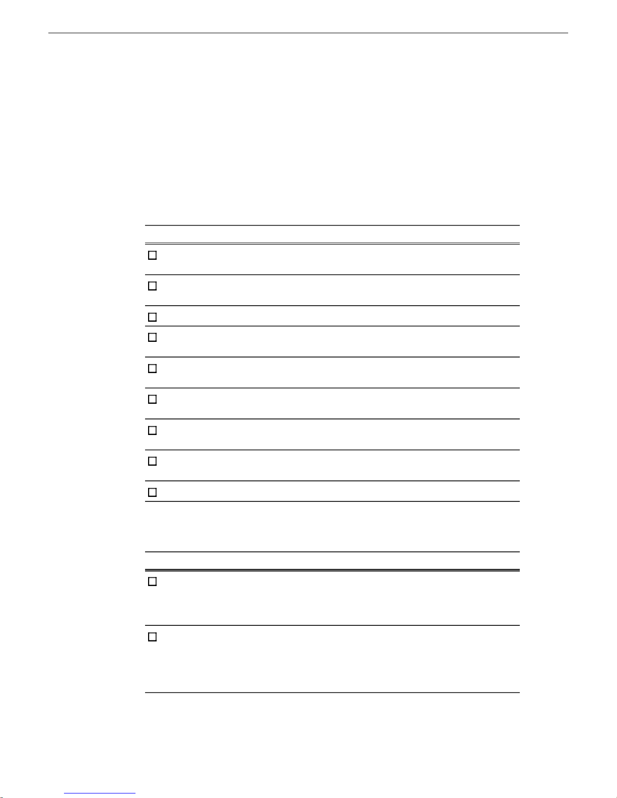
Optional equipment checklist
Use items in this checklist as appropriate for the optional equipment you are installing
in your Aurora Edit workstation.
CommentInstructionsTask
Install video board and
breakout box
Connect audio/video cables
to breakout box
Connect audio mixer
Connect video tape
recorder
Connect jog/shuttle
controller
Connect motorized fader
or effects controller
Assign Com Port
(Windows)
Assign Com Port (Aurora
Edit)
Next: Network setup and implementation checklist
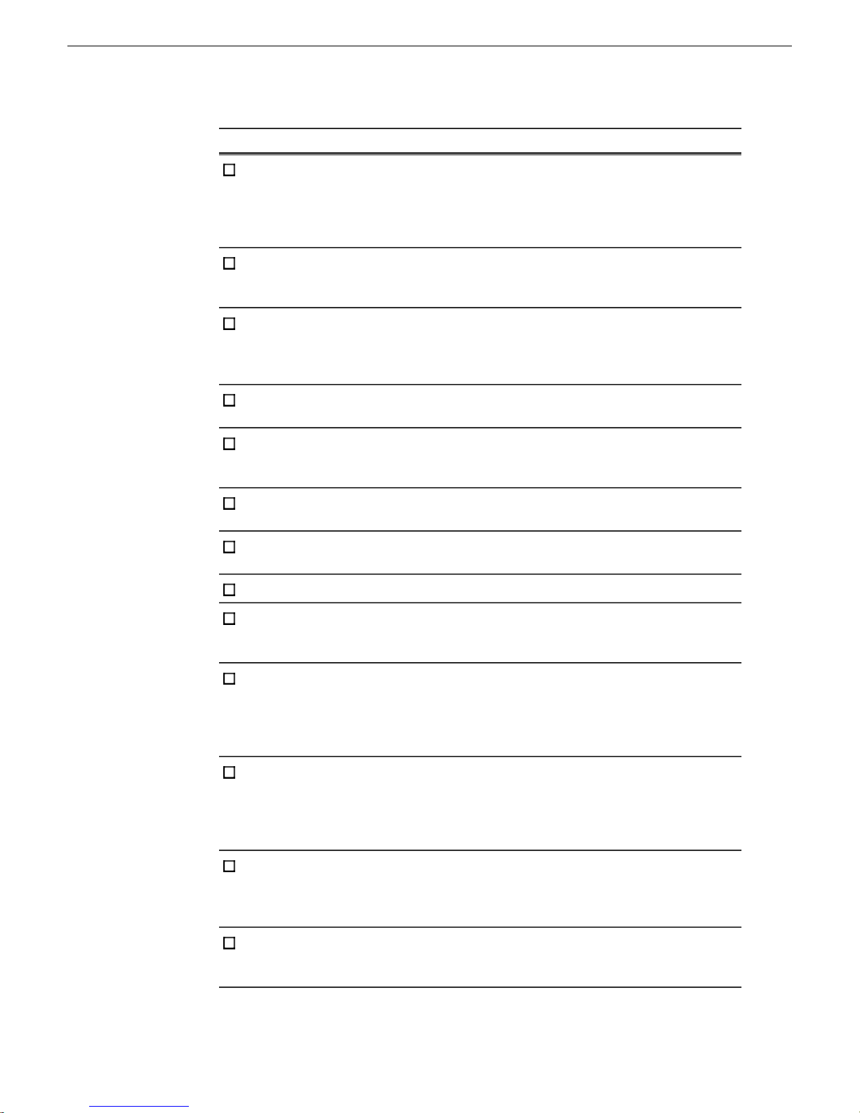
Network setup and implementation checklist
If you have not already
done so, add your storage,
either K2 SAN or NAS, to
the system description
If you have not already
done so, configure your
NAS, and verify that it is
operational.
Installation and Service
Manual. For NAS, followstorage, either K2 SAN or
procedures for K2 Nearline
SAN.
CommentInstructionsTask
Modify your existing
system description.
—Refer to the K2 SAN
12 Aurora Edit Installation Guide 4 October 2010
Page 13
Preparing for installation
CommentInstructionsTask
If you have Aurora Edit
LD systems on the
corporate LAN, add the
corporate LAN to system
description
devices to the system
description
to the system description
for each of your actual Edit
devices
placeholder devices
Configure the network
interfaces of the
placeholder devices
Install SiteConfig support
on devices if necessary.
Set credentials on devices
if necessary.
Modify your existing
system description.
—Add a group for your Edit
—Add a placeholder device
—Configure the names of the
Specify IP address ranges
and other network details
—Discover your Edit devices
—Assign each discovered
device to its placeholder
device
For each discovered and
assigned device, edit each
If a device connects to
multiple networks, set the
control network interfacenetwork interface. Specify
network settings and apply
them to the device.
IP address first. Also set
the hostname.
If you have Aurora Edit
LD systems on the
corporate LAN, add them
to the system description
and set credentials.
If not already set correctly,
set the hostname of
Make sure the device name
is correct, then make the
discovered devices hostname the same as the
device name.
—Ping each Edit device to
test network
communication
4 October 2010 Aurora Edit Installation Guide 13
Page 14
Preparing for installation
CommentInstructionsTask
Generate host table
information and distribute
point PC all devices to ensure
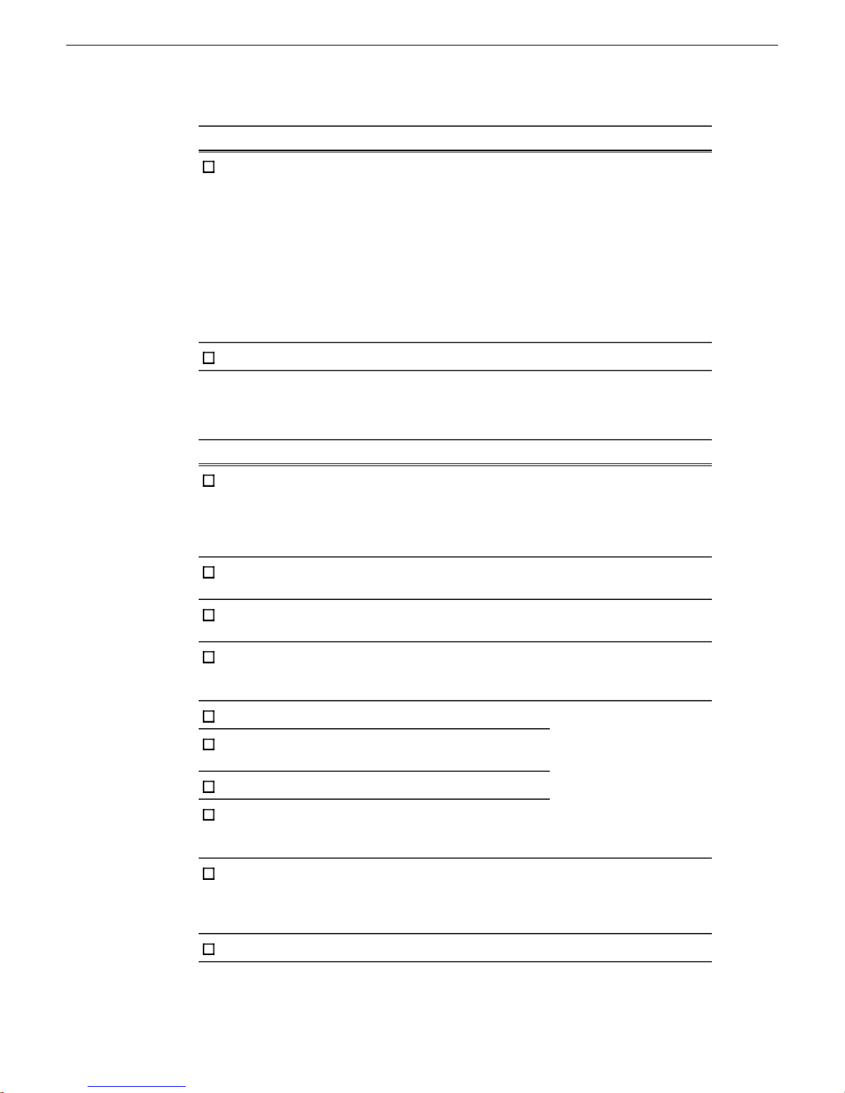
Next: Software update checklist
Software update checklist
Make sure you have
completed network
configuration of allto hosts files on each
network interfaces acrossdevice and on the control
complete and valid host
table information. You can
use SiteConfig to copy
hosts files to devices, or
you can manage hosts files
yourself.
CommentInstructionsTask
—Add/remove software roles
Make sure software roles
match the software that
should be installed on each
device, according to your
system design.
—Add Edit devices to the
deployment group
—Place software on control
point PC
Create a deployment group
Procure the correct version
of software installation
files and prerequisite files.
Check software on devices
Refer to the release notes
for your product.
Add software to
deployment group
Set deployment options
Upgrade/install software to
devices from control point
PC
If using Final Cut Pro with
Aurora Edit, install and
K2 FCP Connect
Installation Manual
These tasks are not
supported by SiteConfig.
license K2-FCP-Connect. Do them manually, at each
local device.
Next: Configuration checklist
14 Aurora Edit Installation Guide 4 October 2010
Page 15
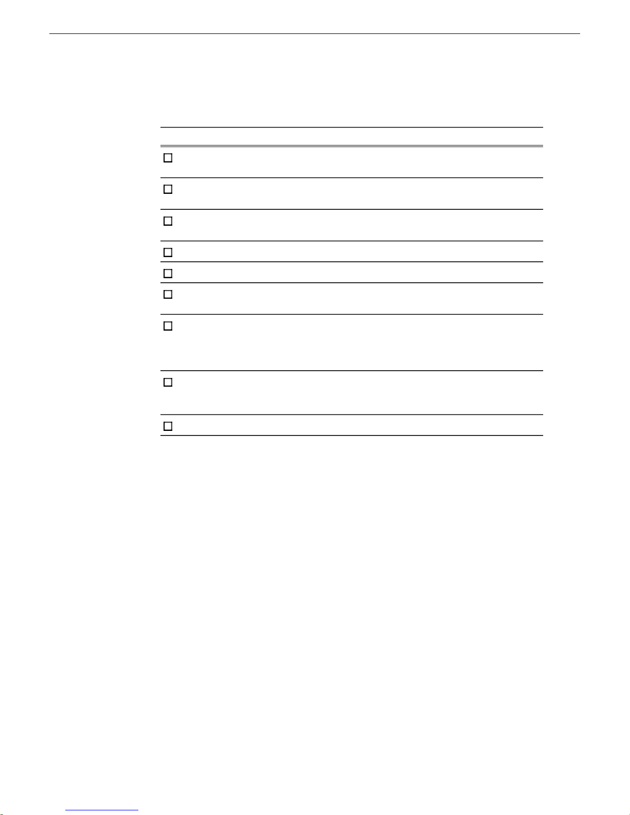
Configuration checklist
Set up media files for
sharing
Add video sources to
Aurora Edit
Set Options
(Tools/Options)
Configure Smartbins
Configure Conform Server
Design Aurora Security
Schema
Preparing for installation
CommentInstructionsTask
If K2 FCP Connect is
installed and licensed,
configure Macintosh
systems on K2 storage.
If using K2 FCP Connect,
configure Aurora Edit for
using Final Cut Pro.
Next:
K2 FCP Connect
Installation Manual
4 October 2010 Aurora Edit Installation Guide 15
Page 16

Page 17

Chapter 2
Installing Aurora Edit Hardware
This section contains the following topics:
• Aurora Edit Components
• Installing Optional Equipment
4 October 2010 Aurora Edit Installation Guide 17
Page 18

Installing Aurora Edit Hardware
Aurora Edit Components
The Aurora Edit application is part of the Aurora Suite of products that consists of
several components that comprise a total digital news production system. All Aurora
Edit applications run on the Aurora Edit platform. For a list of system specifications
for customer-supplied hardware qualified for use with Aurora Edit, refer to the Version
Compatibility section. This information is also included in the Aurora Edit Release
Notes on the CD-ROM where the most recent information is always included.
Refer to the Aurora Edit Release Notes for the most updated information for the
following:
• System Specifications for qualified laptops, desktop computers, and workstations
• HP Workstation Board Assignments
• Compatible DSM Components
• Compatible Grass Valley Products
• Compatible Third Party Products
Workstation Components
The Aurora Edit application is provided on a CD-ROM and installed on a
customer-supplied laptop, desktop computer, or workstation depending on the editing
application needed. When you order your system, you will choose the components
needed for your facility based on your system design.
NOTE: For a list of supported hardware configurations, see the latest Aurora Edit
Release Notes included on the CD and online for the most up-to-date information
on system specifications and software updates.
System components can include:
• Keyboard and Mouse
A keyboard and mouse can be used to control the Aurora Edit and Aurora Edit LD
functions. The keyboard and mouse are customer-supplied. Included with each
Aurora Edit application CD-ROM is a set of keyboard stickers that are applied to
the standard keyboard to make the key strokes compatible with the current Aurora
Edit software version. A customer-supplied laptop computer can also use the
keyboard stickers in the same manner to control Aurora Edit or Aurora Edit LD.
• Monitor
Aurora Edit workstations support either one or two monitors. In a dual-monitor
configuration, one monitor is typically used to display bins while the other displays
other Aurora Edit application components.
• Breakout Box (BOB)
18 Aurora Edit Installation Guide 4 October 2010
Page 19

Aurora Edit supports an option that includes an I/O board that connects to a
rackmountable Breakout Box (BOB) to provide multiple analog and SDI video
and audio inputs and outputs.
• External Control Devices
Standard USB jog/shuttle controllers are acceptable. For an officially qualified list
of devices used on Aurora Edit check with your sales representative when you plan
your system design or contact customer support.
Storage Options
The Aurora Edit system provides three options for storing files:
Local (standalone) on a workstation, computer, or laptop not tied to a shared strorage
solution.
NOTE: In Local mode, no DSM or Smartbins are possible, as well as other
network-required functionality.
Installing Aurora Edit Hardware
NAS (Network Attached Storage) network, a shared storage network consisting of:
• A NAS Server to manage the network file systems
• RAID arrays to provide media storage
• Database System Manager (DSM) to host the News database and (optionally) the
SmartBins Service
NAS networks support Gigabit Ethernet networking.
K2, a shared storage network, consisting of these components:
• A K2 Media Server to manage network file systems
• RAID arrays to provide media storage
• Gigabit Ethernet Switches to connect the K2 Media Server to Aurora Edit clients
• A Control Point PC to K2 Configuration application
• A Database System Manager (DSM) to host the News database and (optionally)
the SmartBins Service
K2 networks use Gigabit Ethernet networking.
Installing Optional Equipment
Aurora Edit allows you to connect a variety of specialized optional equipment to
enhance your editing capabilities. This includes an optional AJA Video Breakout Box
(BOB) and video board. Other interfaces include customer-supplied external controllers
such as a jog shuttle, motorized fader, and effects controllers.
4 October 2010 Aurora Edit Installation Guide 19
Page 20

Installing Aurora Edit Hardware
Optional Breakout Box and Video I/O Board
Qualified Aurora Edit workstations can be equipped with an optional rack-mountable
AJA Video Breakout Box (BOB) with an I/O video board that installs in a slot in the
Aurora workstation.
This option provides additional high-quality analog and digital audio and analog,
component, and SDI video sources, in addition to one HDMI (High Definition
Multimedia Interface) input and one HDMI output. It allows interfacing to various
external devices such as tape decks and cameras as well as HDMI sources. When the
I/O Video board is installed in the workstation during initial installation, the necessary
software components for this option will be installed when the Aurora Edit software
is deployed using the SiteConfig application.
Installing the Video I/O Board and Connecting to the Breakout Box (BOB)
Install the video I/O board in the workstation, then connect it to the rear of the Breakout
Box (BOB) as described below.
NOTE: The previous version Breakout Box (BOB) and video I/O board had three SDI BNC
connectors and no HDMI connectors and had a differenct breakout cable. Cable it in the
same manner by following the labeled cables.
1. Install the video I/O board in the correct workstation slot.
2. Connect the video board to the rear of the breakout box (BOB) using the two cables
provided. One end of the cables attaches to the video board and the other to the
back of the BOB. The cables included are listed below and labeled clearly for
installation:
a) Connect the 60-pin to 60-pin cable to the 60-pin connector on the video board
installed in the workstation and J1 on the rear of the Breakout Box (BOB).
b) Connect the breakout cable with two BNCs labeled SDI OUT to J5 and SDI IN
to J4 on the BOB and in the same order (OUT, IN) to the video card, installed
in the workstation, then connect the two HDMI connectors Iabeled HDMI OUT
to J3 and HDMI IN to J2 on the BOB and in the same order (OUT, IN) to the
video board in the workstation.
Connecting Cables to the Breakout Box
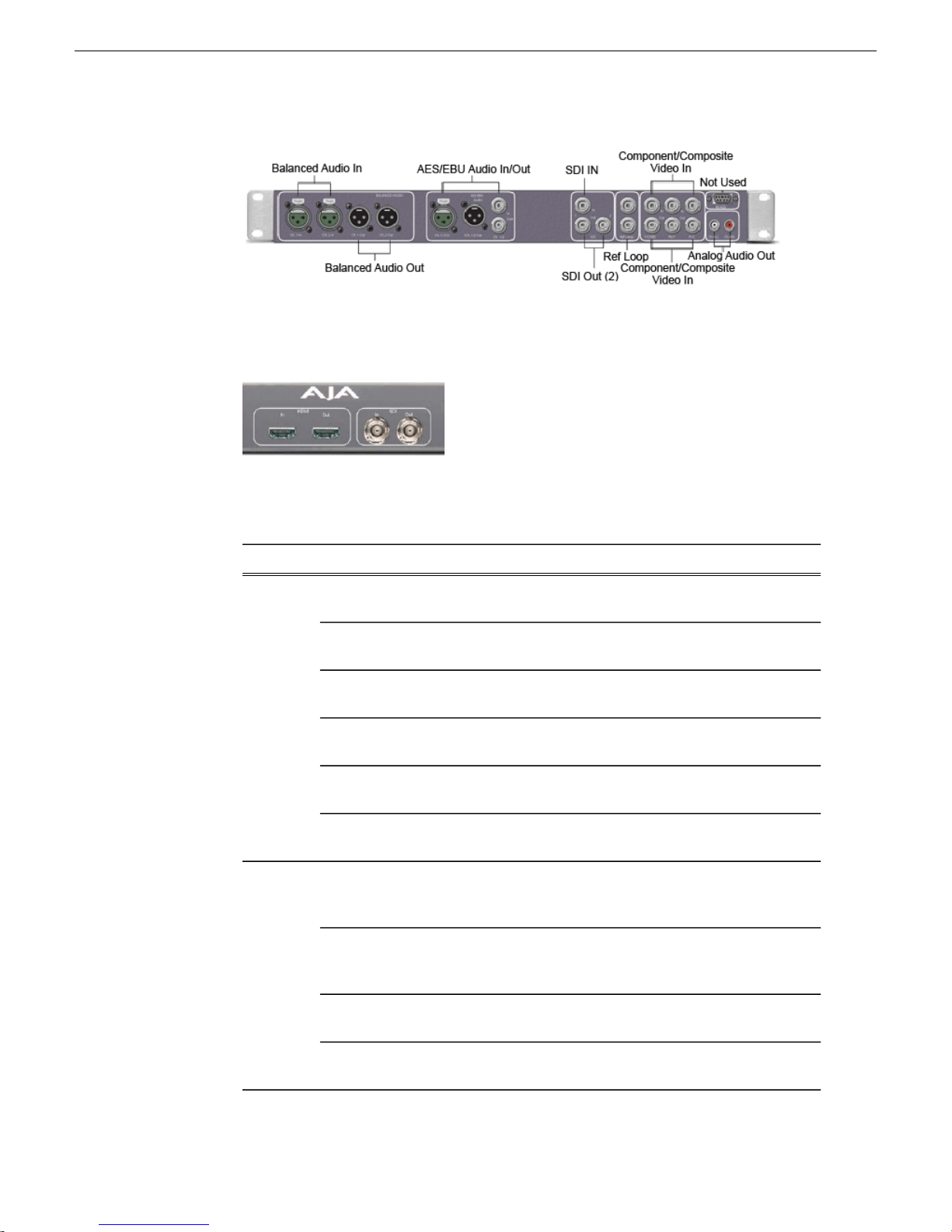
The following illustrations and table detail how to connect video and audio cables to
the breakout box to interface external equipment to your Aurora Edit system.
The image below illustrates the previous version of the HDR Breakout Box (BOB)
with three SDI connectors (one IN and two OUT) and no HDMI connectors. This
BOB requires a specific video board and cable set as specified in the option model.
20 Aurora Edit Installation Guide 4 October 2010
Page 21
Installing Aurora Edit Hardware
The image below shows the latest version AJA Breakout Box (BOB) that is identical
to the older version except it now has two SDI connectors and two HDMI connectors.
This BOB requires a specific video board and cable set as specified in the option
model.
The table below gives cabling information from the AJA Breakout Box (BOB) to
external devices.
NOTE: This table assumes VTRs are operating in playout to tape mode.
Analog
Audio
(without
mixer)
Digtial
Audio
VTR Channel 1
output
VTR Channel 2
output
BOB Balanced Left
Out
BOB Balanced Right
Out
BOB Unbalanced
Left Out
BOB Unbalanced
Right Out
VTR AES/EBU
Channels 1&2 Output
BOB AES/EBU
Channels !&2 Output
BOB Unbalanced
Left Out
Cable TypeToFromInput
XLR-female to XLR-maleBOB Balanced IN
left channel
XLR-female to XLR-maleBOB Balanced IN
right channel
XLR-male to XLR-femaleVTR Channel 1
input
XLR-male to XLR-femaleVTR Channel 2
input
RCA-male to XLR or 1/4" maleLeft desktop
speaker
RCA-male to XLR or 1/4" maleRight desktop
speaker
XLR-male to XLR-maleBOB AES/EBU
Channels 1&2
Input
XLR-male to XLR-femaleVTR AES/EBU
Channels 1&2
Input
RCA-male to XLR or 1/4" maleLeft desktop
speaker
4 October 2010 Aurora Edit Installation Guide 21
BOB Unbalanced
Right Out
RCA-male to XLR or 1/4" maleRight desktop
speaker
Page 22

Installing Aurora Edit Hardware
Cable TypeToFromInput
Single BNC-BNCBOB SDI InputVTR SDI OutputVideo
Single BNC-BNCVTR SDI InputBOB SDI Output
VTR Composite
Output
BOB Composite
Output
VTR Component
Output
BOB Component
Output
1.3a
Controlling a Video Tape Recorder
Machine control of external devices such as VTRs/camcorders and other control
devices is done through an RS-422 remote serial interface or a USB port. Check the
specifications for your specific workstation for RS-422 connector requirements. In
some cases, the workstation must have an optional RS-422 PCI card installed. You
may also use the local RS-232 port on the workstation with an RS-422 adapter for
tape deck serial control applications.
Single BNC-BNCBOB Composite
Input
Single BNC-BNCVTR Composite
Input
Tri BNC-BNC harnessBOB Component
Input
Tri BNC-BNC harnessVTR Component
Input
HDMI Audio/Video cableBOB HDMI InputHDMI Device OutputHDMI
HDMI Audio/Video CableHDMI MonitorBOB HDMI Output
Once cabling is complete, the workstation port must be configured in the Aurora Edit
application to control the external device. Also configure the port on the Controller
card for DCE (controller).
NOTE: The serial interface to the Aurora system is made to a connection on the
rear of the workstation. Do not use the Breakout Box (BOB) Machine Control
connection.
Connecting External Controllers to Aurora Edit
Aurora Edit supports three types of external controllers: the Motorized Fader Controller,
the Jog/Shuttle Controller, and the Effects Controller as described in the table below.
Control connections for these devices are USB or RS-422 depending on the device.
An optional PCI board with an RS-422 machine control port must be installed in the
workstation for correct RS-422 control. Check the specifications for your workstation
type in Appendix B, Workstation Slot Map, for slot installation location of the optional
PCI RS-422 board.
22 Aurora Edit Installation Guide 4 October 2010
Page 23

Installing Aurora Edit Hardware
DescriptionController
Jog Shuttle
Motorized Fader
Effects
Assists editing with a jog/shuttle wheel for convenient searching, buttons
to minimize keyboard strokes, and a backlit LCD timecode display.
Assists audio mixing with four touch-sensitive, motorized faders, 16
channel switches, 4 function keys, and bank shift buttons.
Assists effects editing with a 3–axis joystick mechanism, five rotary
encoders, and 10 switches.
Connecting a Jog/Shuttle Controller
Your workstation should be powered down for this task.
1. Plug the controller’s 9-pin connector into the RS-422 port on the optional PCI
board on the back of the Aurora Edit workstation (COM4). The port should be set
for DTE (Device).
2. Plug the controller’s power connector into a DC power adapter connection.
3. Verify that the following information appears on the controller’s display when it
powers up:
Grass Valley
Aurora Edit
Rev x.xx
4. Turn on your Aurora Edit workstation.
Connecting a Motorized Fader or Effects Controller
Your workstation should be powered down for this task.
1. Plug the controller’s USB connector into one of the two available USB ports on
the back of your Aurora Edit workstation (usually COM5 for the Motorized Fader
Controller and COM6 for the Effects Controller).
2. If you are connecting the Motorized Fader Controller, plug the controller’s power
connector into a DC power adapter connection.
The Effects Controller is powered via the USB cable.
3. Turn on your Aurora Edit workstation.
4. When the New Hardware Wizard appears, follow the directions on the screen.
5. When asked for the controller’s driver, insert the Aurora Edit CD and navigate to
\Drivers\JLC USB Drivers.
6. Finish the new hardware installation.
4 October 2010 Aurora Edit Installation Guide 23
Page 24

Installing Aurora Edit Hardware
Assigning a COM Port (Windows)
To verify that the COM port is set correctly in the Windows Device Manager:
1. Right-click on My Computer and select Properties.
2. Click the Hardware tab on the System Properties window and then click Device
Manager.
3. Click the * symbol next to the Ports item.
4. Click on JLCooper USB to Serial (COM#) and select Properties.
5. Click the Port Settings tab on the Properties tab and click Advanced.
6. Select the correct COM Port Number.
7. Click OK to close the Advanced window, and again to close the Properties window.
Assigning a COM Port (Aurora Edit)
To use any of the controllers, you need to assign a specific Aurora Edit COM port for
the controller. Aurora Edit has pre-configured COM ports as follows:
COM
Port
Aurora Playout GPIOGPIO1
2
Video Tape Recorder (VTR)RS-4223
Jog/Shuttle ControllerRS-4224
Motorized Fader ControllerUSB5
Effects ControllerUSB6
To assign a COM port:
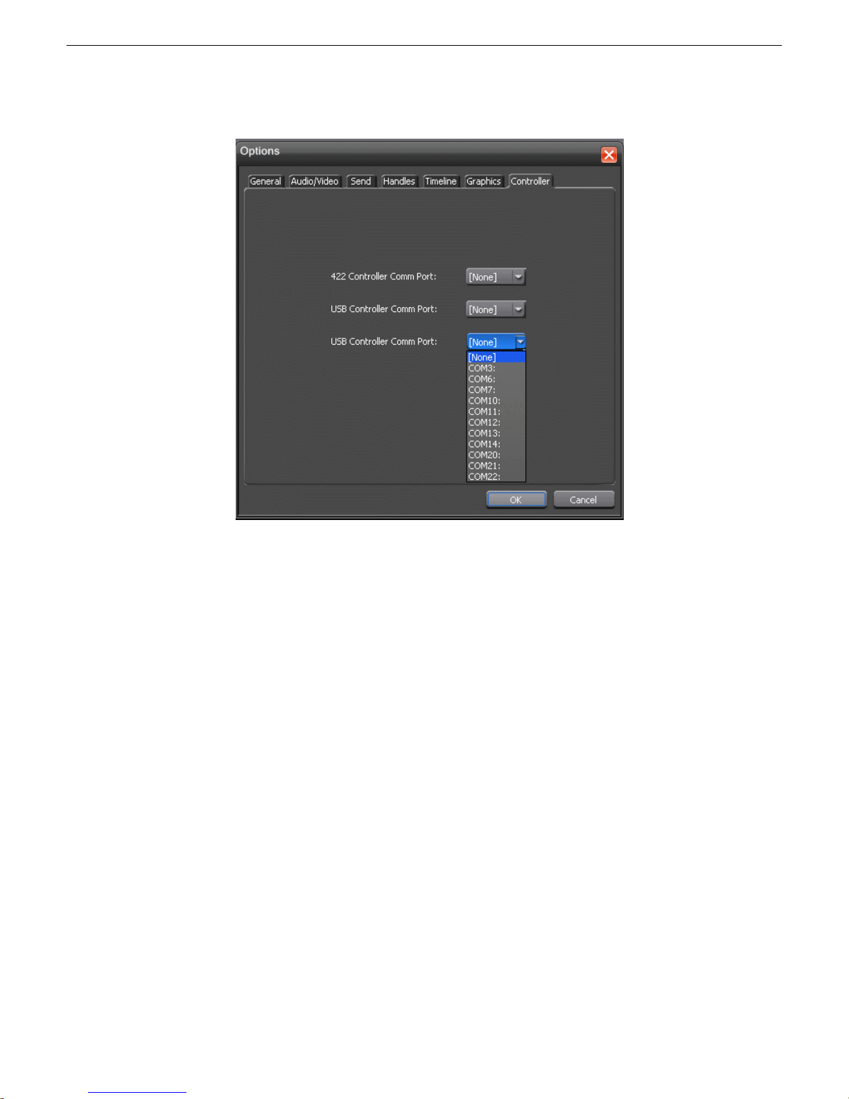
1. In the Aurora Edit application, choose the Tools | Options | Controller pulldown to
bring up the Controller window.
24 Aurora Edit Installation Guide 4 October 2010
Page 25
Installing Aurora Edit Hardware
2. For the Jog/Shuttle Controller, select the correct COM port from the 422 Controller
Comm Port drop-down list; for the other controllers, select the correct COM port
from the USB Controller Comm Port drop-down lists.
The COM port needs to match the number of the USB port where you connected
the controller.
3. Click OK.
You can now use the controller to control features on Aurora Edit.
4 October 2010 Aurora Edit Installation Guide 25
Page 26

Page 27

Chapter 3
Configuring the network
This section contains the following topics:
• Network setup and implementation checklist
• About NewsShare
• About K2 networks
• About SiteConfig
• About developing a system description
• Adding NAS to system description
• About the corporate LAN
• About software deployment on the corporate LAN
• Configuring the corporate LAN
• Adding a group
• Adding a device to the system description
• About device and host names
• Modifying a device name
• About IP configuration of network interfaces on devices
• Modifying unassigned (unmanaged) network interfaces on Edit devices
• About SiteConfig support on Aurora Edit devices
• Installing SiteConfig support
• Installing and configuring SiteConfig support for Aurora Edit LD
• Set credentials
• Discovering devices with SiteConfig
• Assigning discovered devices
• Modifying Edit device managed network interfaces
• Adding Aurora Edit LD workstations for software deployment
• Setting credentials for a specific device
• Making the host name the same as the device name
• Pinging devices from the control point PC
• About hosts files and SiteConfig
• Generating host tables for devices with SiteConfig
• Setting Up the Host Table
4 October 2010 Aurora Edit Installation Guide 27
Page 28
Configuring the network
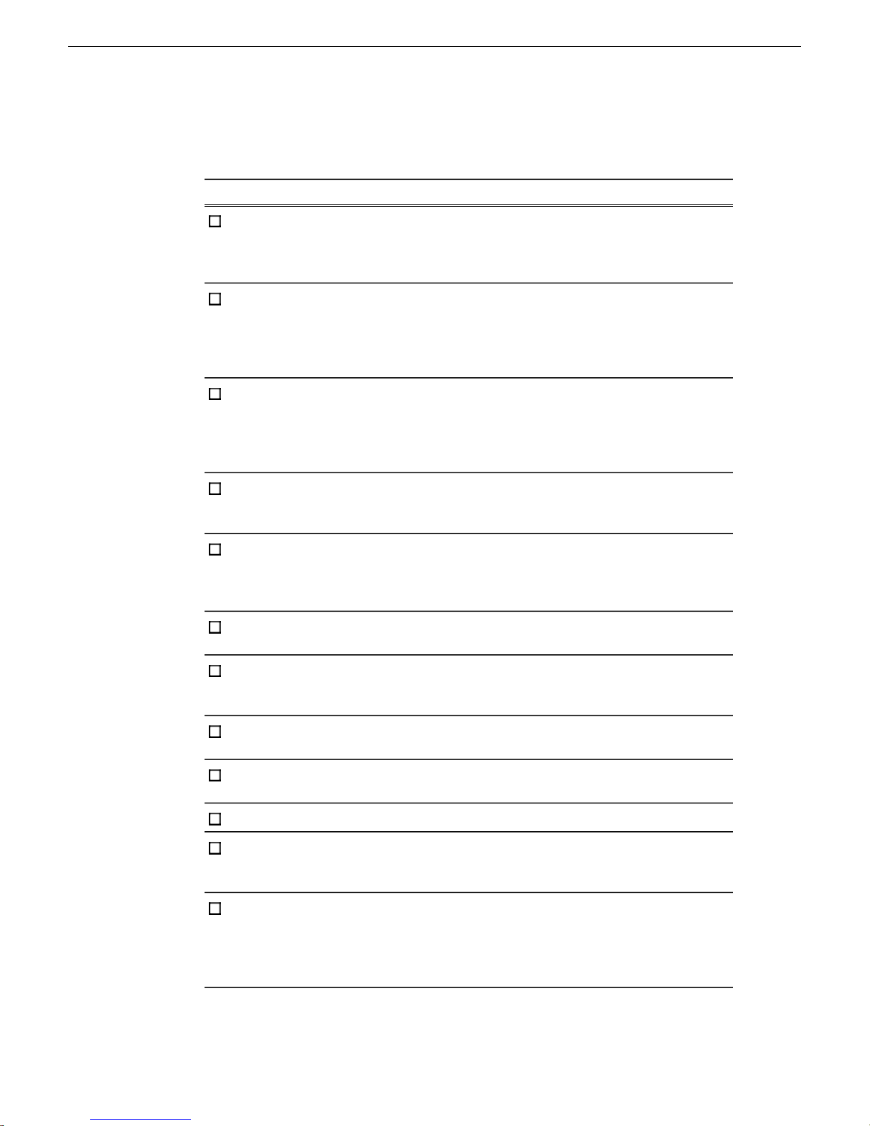
Network setup and implementation checklist
CommentInstructionsTask
If you have not already
done so, add your storage,
either K2 SAN or NAS, to
the system description
If you have not already
done so, configure your
NAS, and verify that it is
operational.
If you have Aurora Edit
LD systems on the
corporate LAN, add the
corporate LAN to system
description
devices to the system
description
to the system description
for each of your actual Edit
devices
placeholder devices
Modify your existing
system description.
—Refer to the K2 SAN
Installation and Service
Manual. For NAS, followstorage, either K2 SAN or
procedures for K2 Nearline
SAN.
Modify your existing
system description.
—Add a group for your Edit
—Add a placeholder device
—Configure the names of the
Configure the network
interfaces of the
placeholder devices
Install SiteConfig support
on devices if necessary.
Set credentials on devices
if necessary.
device to its placeholder
device
For each discovered and
assigned device, edit each
network settings and apply
them to the device.
28 Aurora Edit Installation Guide 4 October 2010
Specify IP address ranges
and other network details
—Discover your Edit devices
—Assign each discovered
If a device connects to
multiple networks, set the
control network interfacenetwork interface. Specify
IP address first. Also set
the hostname.
Page 29
If you have Aurora Edit
LD systems on the
corporate LAN, add them
to the system description
and set credentials.
Configuring the network
CommentInstructionsTask
If not already set correctly,
set the hostname of
discovered devices hostname the same as the
test network
communication
Generate host table
information and distribute
point PC all devices to ensure
Next: Software update checklist
About NewsShare
Make sure the device name
is correct, then make the
device name.
—Ping each Edit device to
Make sure you have
completed network
configuration of allto hosts files on each
network interfaces acrossdevice and on the control
complete and valid host
table information. You can
use SiteConfig to copy
hosts files to devices, or
you can manage hosts files
yourself.
NewsShare allows Aurora Edit to share a common news database and media volume,
making the editing workflow easier to create and maintain.
NewsShare allows Aurora Edit to share a common news database and media volume,
making the editing workflow easier to create and maintain. You can configure
NewsShare for NAS storage or K2 storage.
About K2 networks
NewsShare allows Aurora Edit to share a common news database and media volume,
making the editing workflow easier to create and maintain. You can configure
NewsShare for NAS storage or K2 storage.
Before creating a NewsShare environment, you first need to install and configure a
K2 Media Server. Refer to the K2 SAN Installation and Service Manual.
4 October 2010 Aurora Edit Installation Guide 29
Page 30

Configuring the network
Many K2 network components, particularly the StorNext File System (SNFS), require
all clients and servers to use fixed IP addresses. If your network uses a DHCP server,
you must create address reservations or a fixed address subnet.
Complete IP connectivity must exist between all DSMs, K2 Media Servers, and Aurora
Edit workstations for a particular K2 network. You might find it convenient to assign
all machines on a K2 network to the same Workgroup.
About SiteConfig
SiteConfig is the recommended tool for network configuration and software
deployment. SiteConfig is a ProductFrame application. ProductFrame is an integrated
platform of tools and product distribution processes for system installation and
configuration.
You can use SiteConfig as a stand-alone tool for planning and system design, even
before you have any devices installed or cabled. You can define networks, IP addresses,
hostnames, interfaces, and other network parameters. You can add devices, group
devices, and modify device roles in the system.
As you install and commission systems, SiteConfig runs on the control point PC. It
discovers devices, configures their network settings, and manages host files. SiteConfig
also manages software installations and upgrades and provides a unified software
package with verified compatible versions for deployment across multi-product systems.
You should use SiteConfig for network configuration and software deployment at
installation and throughout the life of the system in your facility. This enforces
consistent policy and allows SiteConfig to keep a record of changes, which makes the
system easier to maintain and aids in troubleshooting should a problem arise.
SiteConfig displays information from a system description file, which is an XML file.
SiteConfig operates in different modes that correspond to a system’ s life-cycle phases:
network configuration, software deployment, and software configuration. You can
expand nodes and select elements in the tree view and the list view to view and modify
networks, systems, individual devices, software deployment, and configuration settings.
About developing a system description
The topics in this manual assume that you are modifying an existing system description.
Your system description is typically developed using one of the following taskflows:
• For a system in which all devices are new from Grass Valley with one or more K2
SANs, you first create a system description for your K2 SAN or SANs, then add
Browse/MediaFrame, Edit, Ingest, and Playout devices as appropriate. Refer to
the K2 SAN installation and Service Manual for instructions on creating the system
description.
30 Aurora Edit Installation Guide 4 October 2010
Page 31

Configuring the network
• For a system in which all devices are new from Grass Valley with one or more
stand-alone K2 systems, you first create a system description and add your
stand-alone K2 systems, than add other devices as appropriate. Refer to the K2
System Guide for instructions on creating the system description and adding your
stand-alone K2 systems.
• For a system with existing devices running earlier software, you must first migrate
the system to become a SiteConfig managed system. Refer to SiteConfig Migration
Instructions for instructions on migrating your devices to be SiteConfig managed
devices.
If you are using a different taskflow, use the topics in this manual as appropriate and
refer to the SiteConfig User Manual or SiteConfig Help Topics for additional
information.
Your devices must be in a SiteConfig system description in order to be managed by
SiteConfig. When you already have a system description in place, you should use
SiteConfig to modify this system description and add your devices. You can do this
in your planning phase, even before you have devices installed or cabled. Your goal
is to have the SiteConfig system description accurately represent all aspects of your
devices and networks before you begin actually implementing any networking or other
configuration tasks for those devices.
Adding NAS to system description
The NAS is a K2 nearline SAN, so instructions for cabling, networking, and
configuration are in the K2 SAN Installation and Service Manual. If the NAS is not
already included in the SiteConfig system description, add it as follows.
1. In the Network Configuration | Devices tree view, right-click the Site node that
includes your K2 SAN and other connected devices and select Add Site.
In this context, "Site" is a distinct system, such as a K2 SAN or an Aurora Browse
system.
The New Site Wizard opens.
4 October 2010 Aurora Edit Installation Guide 31
Page 32
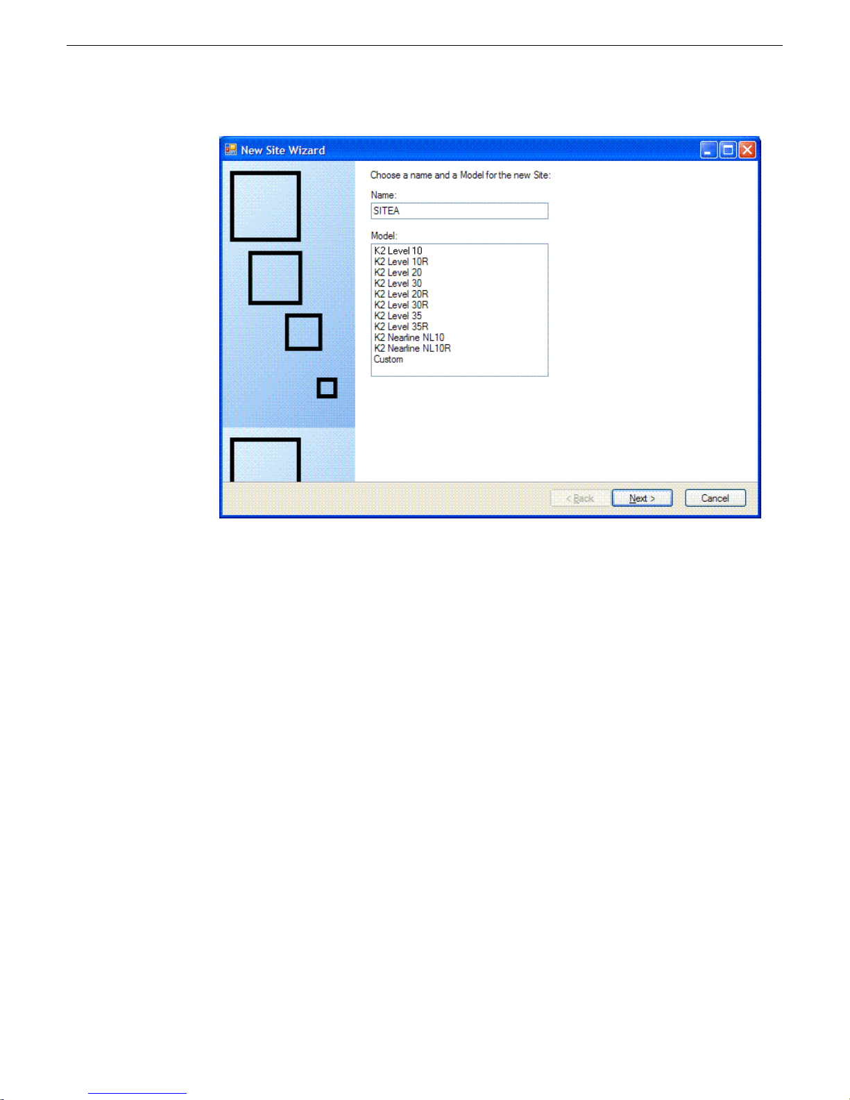
Configuring the network
2. Enter a name for the NAS, considering the following:
• Keep the site name short, as it becomes the root identifier that is the default
prefix for device and network names.
• Sites in the tree view are automatically sorted alphabetically.
3. Select the appropriate K2 Nearline model.
• If the K2 RAID chassis has one controller, select K2 Nearline NL10
• If the K2 RAID chassis has two controllers, select K2 Nearline NL10R
4. Click Next.
The Networks page opens.
32 Aurora Edit Installation Guide 4 October 2010
Page 33
Configuring the network
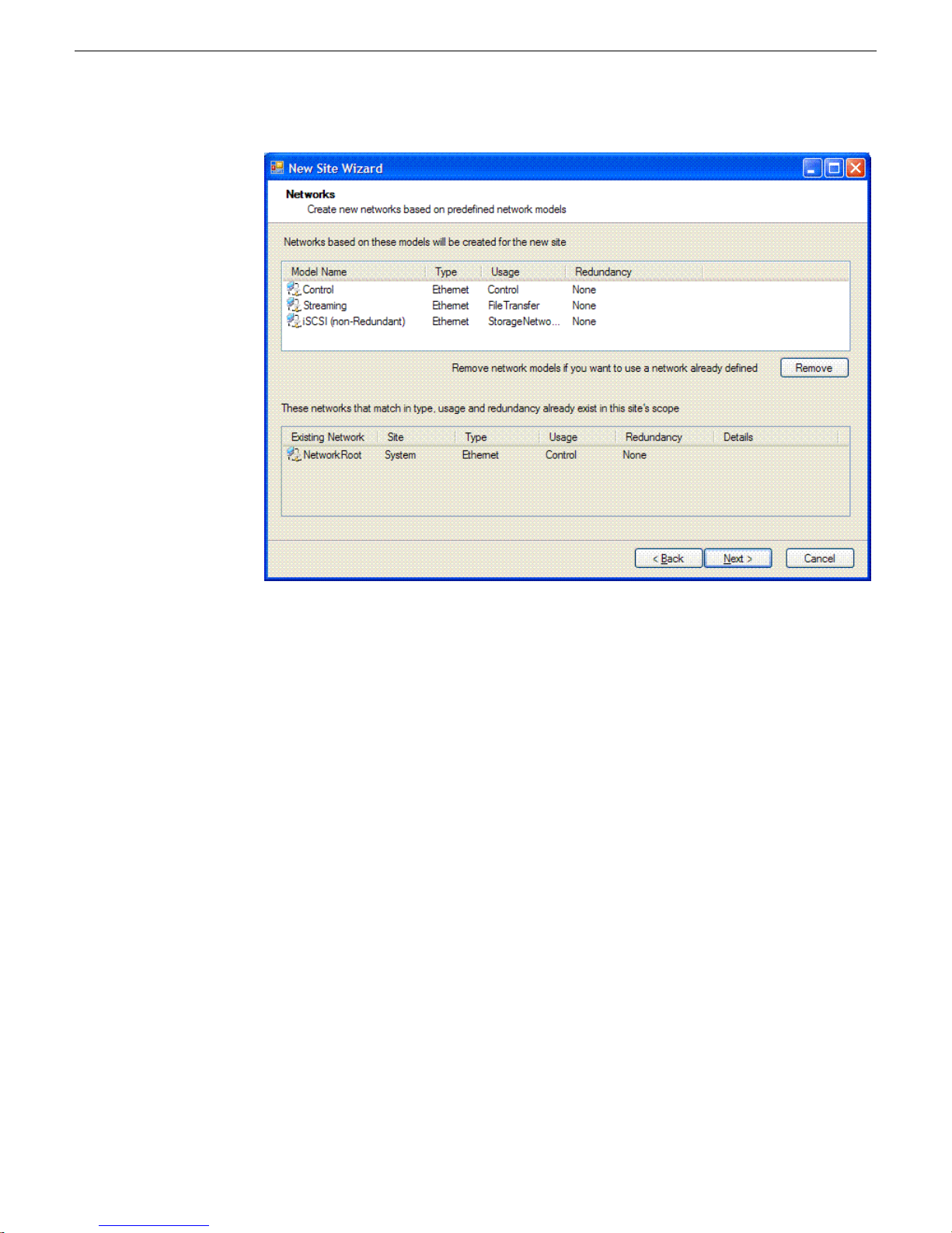
The Networks page displays a list of networks that are defined for the selected
site model. Each of these networks is based on a network model that defines the
type, usage and redundancy of the network. When the New Site Wizard creates
a network, it is based on this model.
5. Remove the control network and the streaming network.
Since child sites inherit the networks defined at their parent(s), if the site you
are creating has a parent site that already contains one of the displayed networks,
then it is not necessary to include that network here.
The parent site of the NAS is the site that contains your K2 SAN, and it already
has a control network and a streaming network.
6. Click Next.
The Devices page opens.
The Devices page shows you the device models that typically comprise a site
based on the model you chose in the first page of the New Site Wizard. The
New Site Wizard creates these devices as part of the site. You can then modify,
remove, or you add devices, including device models that are not shown on this
page.
7. You can select a device model and do one or more of the following:
4 October 2010 Aurora Edit Installation Guide 33
Page 34
Configuring the network
8. Click Next.
Specify the number of devices of that model for the site. If the control is disabled,
•
it means that the number of devices is constrained by the site model. For
example, a site model might be constrained to have one Ethernet switch only.
• Specify the starting IP address of a set of devices of that model. SiteConfig
automatically assigns IP addresses from this range. If you require a different
sequence of IP addresses, you can modify them on each device after the New
Site Wizard completes.
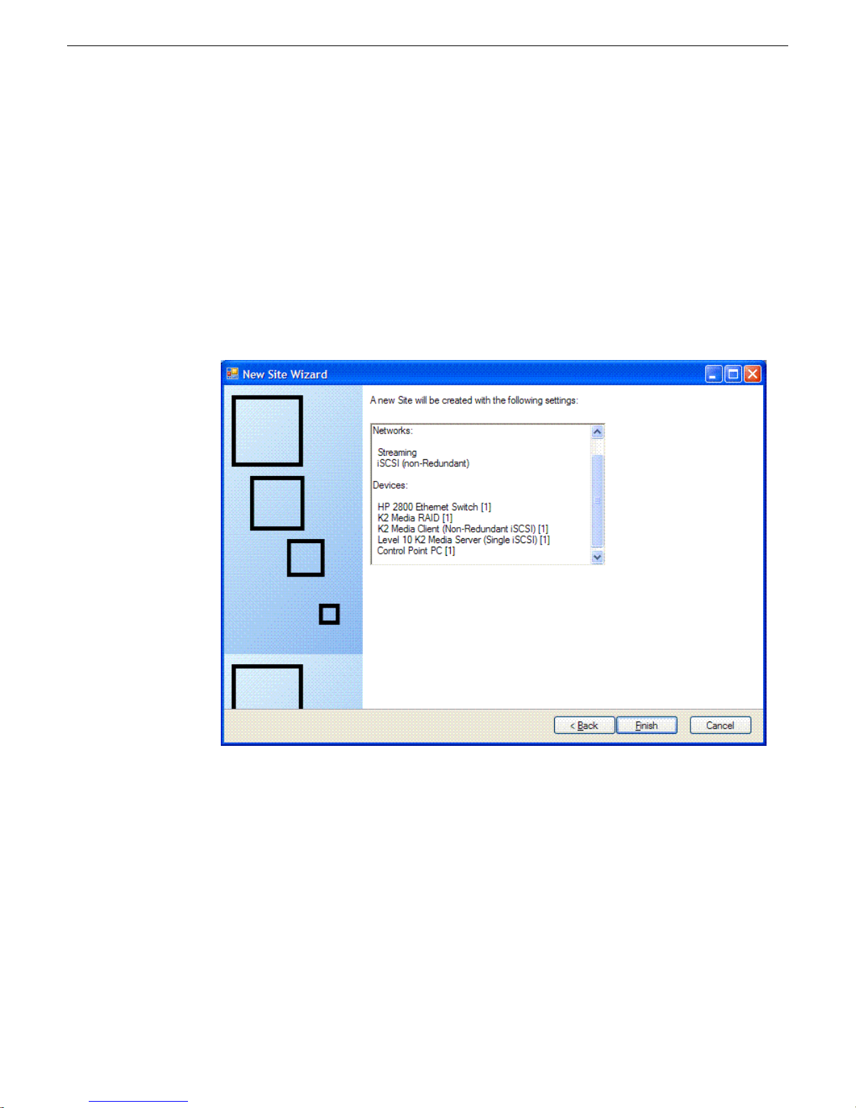
The "...Site will be created..." page opens.
This is the last page and summarizes what the New Site Wizard adds to the tree
view.
9. Click Finish to create the site.
10. Add additional K2 Media Servers as necessary for the NAS.
About the corporate LAN
Some devices, such as the MediaFrame server or Aurora Edit LD workstations, are
on the corporate LAN, which is considered an unmanaged network in SiteConfig. You
34 Aurora Edit Installation Guide 4 October 2010
Page 35

can configure your system description to include the corporate LAN for the following
purposes:
• If a device, such as the MediaFrame server, is on the corporate LAN yet is a
• If a device uses a DNS server on the corporate LAN for name resolution, SiteConfig
• If a device has software that SiteConfig supports and the devices is on the corporate
If the device is on the corporate LAN and is not on a network that is managed by
SiteConfig, you cannot configure network settings on the device.
Related Links
Configuring the corporate LAN on page 35
Configuring the network
SiteConfig managed device, then SiteConfig needs to know the connection for
each network interface on the device, including the corporate LAN connection.
Otherwise, SiteConfig displays error messages.
needs to reference that DNS server.
LAN, such as Aurora Edit LD workstations, you can use SiteConfig to deploy
software to the device via the corporate LAN.
About software deployment on the corporate LAN
If you have Aurora Edit LD workstations that are on a network that SiteConfig does
not manage, such as your corporate LAN, you can configure your system description
to allow software deployment to those devices. This method uses SiteConfig as a
software deployment tool only, as you cannot configure network settings on the device
or manage the device's network. With this method you create an unmanaged network
in SiteConfig, add the DNS server(s) to the control point PC, then when you add the
PC, edit the control interface and set it to the unmanaged network. This allows
communication with the Aurora Edit LD workstations. Then add a placeholder device
for each of your Aurora Edit LD workstations. With this method you do not use
SiteConfig device discovery, and it is not necessary to install a discovery agent on the
Aurora Edit LD workstation. Rather, you configure SiteConfig to look up the address
via DNS or hosts file. This allows the Aurora Edit LD workstation to communicate
as if it was a discovered device. SiteConfig can then deploy software to the device.
If necessary, get help from your IT department to ensure that the SiteConfig PC is
configured to communicate with the Aurora Edit LD workstations on the corporate
network. If SiteConfig can ping it, it can deploy software.
Related Links
Installing and configuring SiteConfig support for Aurora Edit LD on page 45
Adding Aurora Edit LD workstations for software deployment on page 53
Configuring the corporate LAN
1. In the Network Configuration | Networks tree view, select a System node or a Site
node.
4 October 2010 Aurora Edit Installation Guide 35
Page 36

Configuring the network
2. Proceed as follows:
3. Configure the settings for the network as follows:
The networks under that node are displayed in the list view.
• To add a network under the currently selected node, in the tree view right-click
the node and select Add Network.
The Network Settings dialog box opens.
• Type – Select Ethernet
• Usage – Select Control
• Redundancy – Select None
• Name – Enter a name to identify the network in the system description
• Exclude from Host Files – Select the checkbox
• Unmanaged – Select this option, then select DNS and select the checkbox for
IP Address Allocation via DHCP.
• Base IP Address – Do not configure
• Number of IP Addresses – Do not configure
• Subnet Mask – Do not configure
• DNS Servers – Servers providing DNS for name resolution. These DNS server
can be for both managed and unmanaged networks.
• Default Interface Name Suffix – The suffix added to the end of host names to
identify interfaces on this network.
4. Click OK to save settings and close.
5. If you added a network, it appears in the Network Configuration | Networks tree
view at the bottom of the list.
Related Links
About the corporate LAN on page 34
Adding a group
1. In the Network Configuration | Networks tree view, right-click a site node and select
Add Group.
The group appears in the tree view.
2. Right-click the group and select Rename.
3. Enter the desired name for the group.
Adding a device to the system description
Prerequisites for this task are as follows:
36 Aurora Edit Installation Guide 4 October 2010
Page 37
Configuring the network
• The system description contains a group.
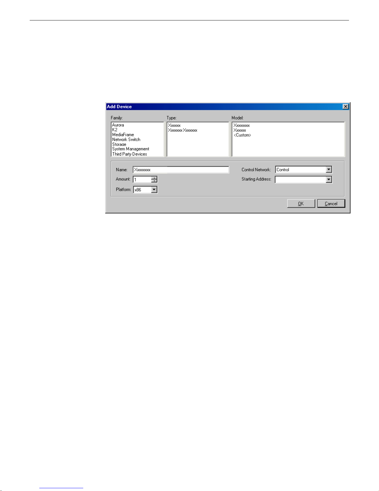
1. In the Network Configuration | Devices tree view, right-click a group and select Add
Device.
The Add Device dialog box opens.
2. Configure settings for the device you are adding as follows:
• Family – Select Aurora.
• Type – Select the appropriate type of Aurora device.
• Model – Select the appropriate model.
• Name – This is the device name, as displayed in the SiteConfig device tree view
and device list view. This name can be different than the host name (network
name). You can accept the default name or enter a name of your choice. Devices
in the tree view are sorted alphabetically.
• Amount – You can add multiple devices, as currently defined by your settings
in the Add Device dialog box. An enumerator is added to the name to create a
unique name for each device added.
• Control network – Select the control network.
• Starting Address – Select from the list of available addresses on the selected
control network. If adding multiple devices, this is the starting address, with
addresses assigned sequentially to each device added.
3. Click OK to save settings and close.
4. Repeat these steps for each of your devices.
4 October 2010 Aurora Edit Installation Guide 37
Page 38

Configuring the network
About device and host names
In SiteConfig, a device can have different names, as follows:
• Device name — This is a name for display in SiteConfig only. It is stored in the
• Host name — This is the network name of the device. SiteConfig has a default
In most cases it is recommended that the Device name and Host name be the same.
This avoids confusion and aids troubleshooting.
The Device name can serve as a placeholder as a system is planned and implemented.
During the install/commission process, when you reconcile a device's current and
planned network interface settings, the Host name as configured in the system
description can be overwritten by the host name on the actual device. However, the
Device name configured in the system description is not affected. Therefore it is
recommended that in the early planned stages, you configure the Device name to be
the desired name for the device, but do not yet configure the Host name. Then, after
you have applied network interface settings, you can change the Host name to be the
same as the Device name. This changes the host name on the actual device so that
then all names are in sync.
SiteConfig system description, but not written to the actual device. It is displayed
in the device tree view and in the device list view. It can be a different name than
the device’s host name.
naming convention for host names which you can use or override with your own
host names.
SiteConfig does not allow duplicate device names or host names.
Items in the tree view are automatically sorted alphabetically, so if you change a name
the item might sort to a different position.
Modifying a device name
1. In the Network Configuration | Devices tree view, right-click a device and select
Rename.
2. Type in the new name.
Note that this does not change the hostname on the physical device. If you want
the hostname to match the device name, you must also modify the hostname.
About IP configuration of network interfaces on devices
You can perform IP configuration of network interfaces when working with a
placeholder device prior to discovery. When you add a device and choose a particular
model, the model defines the number, type and usage characteristics of network
interfaces to expect on such a device.
38 Aurora Edit Installation Guide 4 October 2010
Page 39
You can view and edit each network interface and set up IP configuration selecting
an appropriate IP from the network to which each interface connects. The process for
editing IP configuration varies, depending on the device's phase.
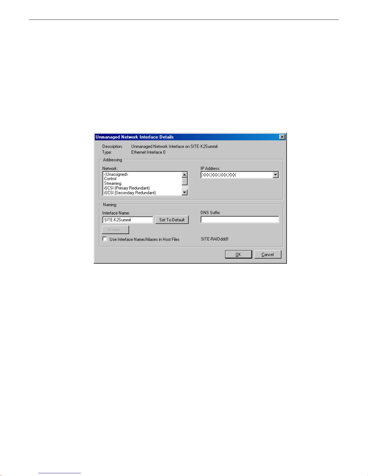
Placeholder device IP configuration
On a placeholder device, you edit network interfaces using the Unmanaged Network
Interfaces dialog box.
Configuring the network
The Unmanaged Network Interfaces dialog box allows you only to save changes to
the system description.
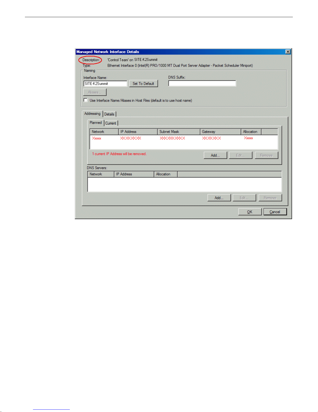
Discovered device IP configuration
On a discovered device, you edit network interfaces using the Managed Network
Interfaces dialog box.
4 October 2010 Aurora Edit Installation Guide 39
Page 40
Configuring the network
The Managed Network Interfaces dialog box allows you to edit and save changes to
the device.
Modifying unassigned (unmanaged) network interfaces on Edit
devices
Prerequisites for this task are as follows:
• The system description has one or more Aurora Edit devices that are placeholder
devices.
• The placeholder device has a one or more unmanaged network interfaces.
Use this task to modify unmanaged network interfaces on Aurora Edit devices as follows:
• Aurora Edit
• Conform Server
• DSM
• FTP Server
• SmartBin Server
40 Aurora Edit Installation Guide 4 October 2010
Page 41
Configuring the network
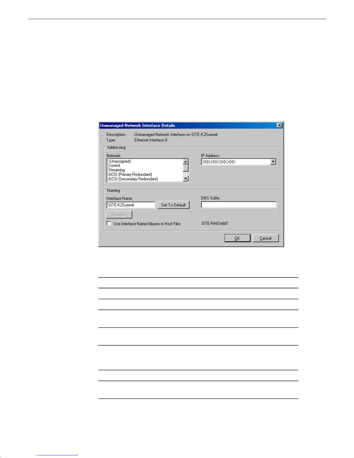
1. In the Network Configuration | Devices tree view, select an Aurora Edit placeholder
device.
The interfaces for that device are displayed in the interfaces list view.
2. In the interfaces list view, right-click an interface and select Edit.
The Unmanaged Network Interface Details dialog box opens.
3. Configure the settings for the interface as follows:
Setting...
Name
Set to Default
Use Interface
Name/Aliases
in Host Files
DNS Suffix
For control network interface
Control is requiredNetwork
The IP address for this interface on the network. Required.IP Address
The device host name. Required.Interface
Not recommended. Sets the interface name to SiteConfig default
convention, based on the root Site name and device-type.
Unselected is required. Since not selected, the default behavior
occurs, which is to use the device host name in the hosts file.
Not allowedAliases
Allowed, if applicable to the network. The DNS suffix is added to
the interface name.
4 October 2010 Aurora Edit Installation Guide 41
Page 42

Configuring the network
For media (iSCSI) network interfaceSetting...
Network
Name
Name/Aliases
in Host Files
If on a basic K2 SAN, iSCSI (non-Redundant) is required for the
iSCSI interface.
If on a redundant K2 SAN, iSCSI (Primary Redundant) is required
for the iSCSI interface on devices connecting to the A side of the
redundant K2 SAN
If on a redundant K2 SAN, iSCSI (Secondary Redundant) is required
for the iSCSI interface on devices connecting to the B side of the
redundant K2 SAN
The IP address for this interface on the network. Required.IP Address
Disabled, since names are excluded from the hosts file. Disregard.Interface
Disabled, since names are excluded from the hosts file. Disregard.Set to Default
Disabled, since names are excluded from the hosts file. Disregard.Use Interface
Disabled, since names are excluded from the hosts file. Disregard.Aliases
Disabled, since names are excluded from the hosts file. Disregard.DNS Suffix
4. Click OK to save settings and close.
About SiteConfig support on Aurora Edit devices
Before SiteConfig can be used to discover or manage a device, the device must meet
the following requirements:
• The device must be a Microsoft Windows operating system device.
• The device must have Microsoft .NET version 2.0 installed, as reported in the
Windows Add/Remove Programs control panel.
• The ProductFrame Discovery Agent service must be running on the device, as
reported in the Windows Services control panel.
For Aurora Edit devices shipped new from Grass Valley with software version 6.5 or
higher, these requirements are pre-installed. These requirements are pre-installed on
recovery images for these systems as well. Therefore, if you suspect a problem with
these requirements, do not attempt to install SiteConfig support requirements. If you
must restore SiteConfig support requirements, re-image the system.
For devices that you purchase and then install software and hardware to build an
Aurora device, you must verify and install SiteConfig support requirements as
necessary.
42 Aurora Edit Installation Guide 4 October 2010
Page 43

Software that meets these requirements is bundled in various components and
installation programs, some of which are available at your SiteConfig install location
as follows:
• The ConnectivityKit folder contains Microsoft .NET. You can copy the contents
of this folder to a device and then run setup.exe to install the software.
• The DiscoveryAgent Setup folder contains the ProductFrame Discovery Agent.
You can copy the contents of this folder to a device and then run setup.exe to
install the software.
Installing SiteConfig support
Use this topic to verify and, if necessary, install SiteConfig support software so that
the device can be discovered and managed by SiteConfig.
For Aurora Edit LD, do not use this topic. Instead, skip ahead and use the next topic.
1. Open the Windows Services Control Panel and look for the following required
item:
Configuring the network
• ProductFrame Discovery Agent
2. Open the Windows Add\Remove Programs Control Panel and look for the following
required item:
• Microsoft .NET Framework 2.0 Service Pack 2
3. Proceed as follows:
• On Aurora product devices, if the ProductFrame Discovery Agent at a version
lower than 1.1.0.185 is installed, use the Windows Add\Remove Programs
Control Panel and uninstall it. On these devices you must uninstall and then
install version 1.1.0.185 or higher, as instructed in next steps.
NOTE: The Discovery Agent can be named the ProductFrame Discovery
Agent, the SiteConfig Discovery Agent, or the SiteConfig Network
Configuration Connect Kit.
• On other devices, if the ProductFrame Discovery Agent is already installed,
you can leave it installed as is.
• On all devices, if either the ProductFrame Discovery Agent or .NET is not
installed, install the required software as instructed in next steps.
4. Navigate to your SiteConfig files or to the SiteConfig install location.
5. To install the ProductFrame Discovery Agent Service do the following:
a) Copy the Discovery Agent Setup subdirectory to the device.
b) In the Discovery Agent Setup directory, double-click the
DiscoveryAgentServiceSetup.msi file.
4 October 2010 Aurora Edit Installation Guide 43
Page 44

Configuring the network
The setup program launches to install the SiteConfig Discovery Agent.
c) Follow the setup wizard.
The setup wizard presents a list of devices types similar to the following:
• K2Server
• GigESwitch
• FCSwitch
• K2Client
• AuroraEdit
• MediaFrameServer
• ControlPoint
• K2Appliance
• K2Standalone
• K2SummitSanClient
• K2SummitStandaloneClient
• IEP
• DSM
• ProxyEncoder
• SmartBinServer
• FTPServer
• ConformServer
• AuroraEditLD
• GenericDevice
• RAIDBaseUnit
• AuroraPlayoutPlatform
• AuroraIngestPlatform
d) From the list, select the device type of the device on which you are installing
the Discovery Agent.
e) Complete the setup wizard.
f) Restart.
The restart is required after the installation.
6. To install .NET 2.0 do the following:
Be sure that .NET is installed before installing the Discovery Agent.
a) From the directory at which the SiteConfig application is installed on the control
point PC, copy the contents of the ConnectivityKit directory to the device.
b) Run setup.exe and install the software.
44 Aurora Edit Installation Guide 4 October 2010
Page 45

Configuring the network
Installing and configuring SiteConfig support for Aurora Edit LD
Use this topic to install software and configure Aurora Edit LD workstations that are
on the corporate LAN to prepare them for SiteConfig software deployment. You can
do this using the following methods:
• Remotely from the SiteConfig control point PC, using a deployment preparation
script that connects to each of your Aurora Edit LD workstations. This requires an
appropriate domain admin account that can access all the devices remotely. Start
with step 1 to use this method.
• Locally at each Aurora Edit LD workstation. This method is described in the last
step of the procedure.
1. On the control point PC, create a text file that lists the hostnames of all the Edit
LD devices you want to prep for SiteConfig software deployment, with one
hostname per line. Name the text file EditLDdevices.txt.
2. Save the text file to the SiteConfig install directory. The default location is
C:\Program Files\Grass Valley\SiteConfig.
3. Open the MS-DOS command prompt as follows.
a) From the Windows desktop, click Start | Run.
b) Type cmd and press Enter.
The MS-DOS command prompt window opens.
4. From the MS-DOS command prompt, cd to the SiteConfig install directory. For
example, type the following sequence of commands, pressing Enter after each
command.
a) C:
b) cd "Program Files"
c) cd "Grass Valley"
d) cd SiteConfig
5. Run the batch file by typing the following and then pressing Enter:
DeploymentPrep.bat {path to the text file} {domain admin
user name}
Example: DeploymentPrep.bat "C:\Program Files\Grass
Valley\SiteConfig\EditLDdevices.txt" CORP_LAN\Administrator
6. Enter the domain admin password for the Aurora Edit LD devices when prompted.
The assumes that the domain admin password is the same for all the devices.
The script connects to each device with the admin user name specified. The
script reports its activities on each device.
If errors occur on a device, they are displayed. The script skips problem devices
and continues on until it completes all devices in the text file list. When complete,
the command prompt is displayed.
4 October 2010 Aurora Edit Installation Guide 45
Page 46

Configuring the network
7. Restart each Aurora Edit LD device on which the script was successful.
8. For each Aurora Edit LD workstation on which the script was unsuccessful or for
Related Links
Adding Aurora Edit LD workstations for software deployment on page 53
About software deployment on the corporate LAN on page 35
which the deployment preparation script is unsuitable, install the Connectivity Kit
on the device and configure as follows:
a) From the directory at which the SiteConfig application is installed on the control
point PC, copy the contents of the ConnectivityKit directory to the device.
b) Run setup.exe and install the software.
c) Check firewall settings on the Aurora Edit LD device as follows and configure
if necessary. The deployment preparation script configures the Windows firewall,
so for devices using the Windows firewall on which you have run the script,
these settings should already be configured.
•
Turn on the file and printer sharing ports - TCP 139, 445, UDP 137, 138.
• Turn on remote desktop - TCP 3389.
d) Restart the Aurora Edit LD workstation.
Set credentials
1. At each local device, view the Windows administrator user account and verify that
the credentials are the same as those that SiteConfig uses to access the device.
SiteConfig is pre-configured to use the following default credentials to access
devices:
Device type
(MediaFrame), Edit,
Ingest, and Playout
devices
2. If necessary, change credentials so they match on the device and in SiteConfig,
using one of the following methods:
• Change the device's credentials to match the credentials that SiteConfig uses
to access the device. This is recommended for most K2 and Aurora devices.
• If your security policies prohibit changing the device's credentials, such as on
Aurora Edit LD workstations on the corporate LAN, in SiteConfig change the
credentials that SiteConfig uses to access the device.
PasswordUsername
adminK2AdministratorAll K2 devices
adminGV!AdministratorAll Aurora Browse
46 Aurora Edit Installation Guide 4 October 2010
Page 47
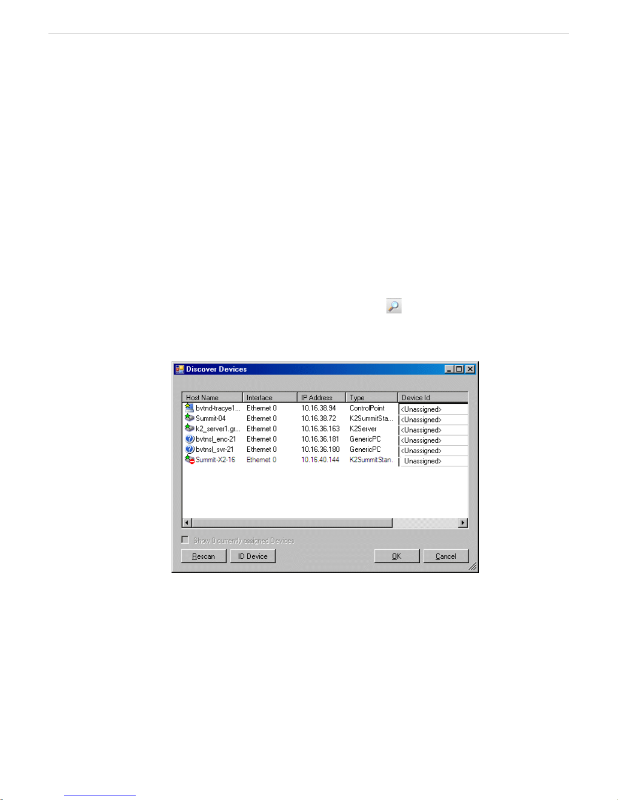
Related Links
Setting credentials for a specific device on page 54
Discovering devices with SiteConfig
Prerequisites for this task are as follows:
• The Ethernet switch or switches that the support the control network are configured
and operational. If multiple switches, ISLs are connected and trunks configured.
• The control point PC is communicating on the control network.
• There are no routers between the control point PC and the devices to be discovered.
• Devices to be discovered are Windows operating system devices, with SiteConfig
support installed.
• Devices are cabled for control network connections.
1. Open SiteConfig on the control point PC.
2. In the toolbar, click the discover devices button.
The Discover Devices dialog box opens.
Configuring the network
A list of discovered devices is displayed.
3. Click Rescan to re-run the discovery mechanism. You can do this if a device that
you want to discover has its network connection restored or otherwise becomes
available. Additional devices discovered are added to the list.
4 October 2010 Aurora Edit Installation Guide 47
Page 48

Configuring the network
Assigning discovered devices
Prerequisites for this task are as follows:
• Devices have been discovered by SiteConfig
• Discovered devices are not yet assigned to a device in the system description
• The system description has placeholder devices to which to assign the discovered
1. If the Discovered Devices Dialog box is not already open, click the discover devices
2. Identify discovered devices.
devices.
button .
The Discover Devices dialog box opens.
• If a single device is discovered in multiple rows, it means the device has multiple
network interfaces. Choose the interface that represents the device's currently
connected control connection. This is typically Ethernet ... 0.
• If necessary, select a device in the list and click ID Device. This triggers an action
on the device, such as flashing an LED or ejecting a CD drive, to identify the
device.
3. To also view previously discovered devices that have already been assigned to a
device in the system description, select Show … currently assigned devices.
The currently assigned devices are added to the list. Viewing both assigned and
unassigned devices in this way can be helpful to verify the match between
discovered devices and placeholder devices.
4. In the row for each discovered device, view items on the Device Id drop-down list
to determine the match with placeholder devices, as follows:
• If SiteConfig finds a match between the device-type discovered and the
device-type of one or more placeholder devices, it displays those placeholder
devices in the list.
• If SiteConfig does not find a match between the device-type discovered and the
device-type of a placeholder device, no placeholder device is displayed in the
list.
5. In the row for a discovered device, click the Device Id drop-down list and select
the placeholder device that corresponds to the discovered device.
If there is no corresponding placeholder device currently in the system
description, you can select Add to create a new placeholder device and then
assign the discovered device to it.
6. When discovered devices have been assigned, click OK to save settings and close.
7. In the Network Configuration | Devices tree view, select each of the devices to which
you assigned a discovered device.
48 Aurora Edit Installation Guide 4 October 2010
Page 49

Modifying Edit device managed network interfaces
Prerequisites for this task are as follows:
• The physical device you are configuring has been discovered and is assigned to a
device in the SiteConfig system description.
• SiteConfig has communication with the device.
• The device is defined in the system description with an appropriate network
interface.
Use this task to modify managed network interfaces on a Aurora Edit devices as follows:
• Aurora Edit
• Conform Server
• DSM
• FTP Server
• SmartBin Server
1. In the Interfaces list view determine the interface to configure, as follows:
• Identify the interface with which SiteConfig is currently communicating,
indicated by the green star overlay icon. This should be the control network
interface.
Configuring the network
• Verify that the interface over which SiteConfig is currently communicating is
in fact the interface defined for the control network in the system description.
If this is not the case, you might have the control network cable connected to
the wrong interface port. The control connection should always be the first port
on the motherboard, except when you have a loopback connection.
• Configure the control network interface first before configuring any of the other
interfaces.
• After you have successfully configured the control network interface, return to
this step to configure each remaining interface.
2. In the Interfaces list view, check the icon for the interface you are configuring.
If the icon has a red stop sign overlay, it indicates that current settings and
planned settings do not match or that there is some other problem. Hover over
the icon to read a tooltip with information about the problem.
3. In the Interfaces list view, right-click the interface you are configuring and select
Edit.
The Managed Network Interface Details dialog box opens.
4 October 2010 Aurora Edit Installation Guide 49
Page 50
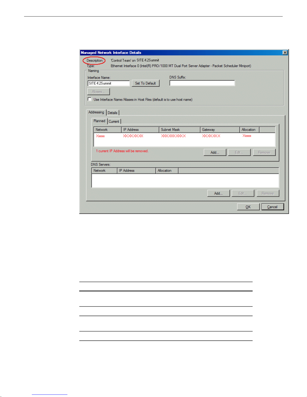
Configuring the network
4. Identify the interface on the discovered device that you are configuring.
• Identify Ethernet LAN adapters by their "Description" name. This is the
Windows connection name. SiteConfig reads this name from the device and
displays it at the top of this dialog box. This is the most accurate way to identify
the network adapter on the discovered device that you are configuring.
5. Configure naming settings as follows:
For network interface Network ConnectionSetting...
The device host name. Required.Interface
Name
Not recommendedSet To Default
DNS Suffix
Allowed, if applicable to the network. The DNS suffix is added to
the interface name.
Not allowedAliases
50 Aurora Edit Installation Guide 4 October 2010
Page 51

Configuring the network
For network interface Network ConnectionSetting...
Use Interface
Name/Aliases
in Host Files
Interface
Name
Use Interface
Name/Aliases
in Host Files
Unselected is required. Since not selected, the default behavior
occurs, which is to use the device host name in the hosts file.
For any network interface of type iSCSISetting...
The text "Unused" is recommended. Displaying this text here serves
as an aid in understanding SAN networks.The iSCSI network has
no name resolution via the hosts file or otherwise, so the text you
enter here is not actually use for name resolution.
Not allowedSet To Default
Not allowedDNS Suffix
Not allowedAliases
Selected is recommended. Since this interface’s network has its
names excluded from the hosts file, this setting has no affect. The
interface name is excluded from the hosts file, regardless of settings
here.
6. Evaluate settings on the Planned tab and change if necessary.
• Compare settings on the Planned tab with settings on the Current tab.
• If you want to keep the current settings as reported in the Current tab, click
Remove to remove the planned settings.
• Do not specify multiple IP addresses for the same interface. Do not use the Add
button.
7. To modify planned settings, do the following:
a) Select the network settings and click Edit.
The Edit IP Address dialog box opens.
4 October 2010 Aurora Edit Installation Guide 51
Page 52
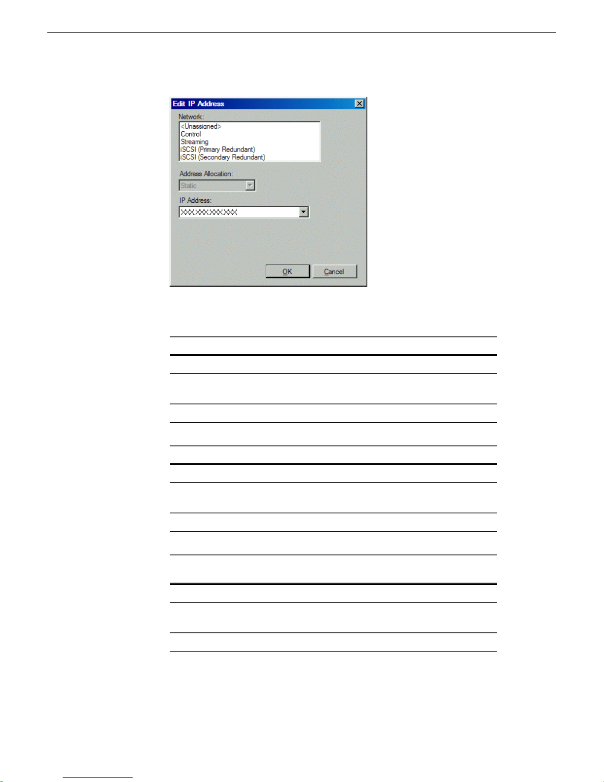
Configuring the network
b) Edit IP address settings as follows:
Allocation
Allocation
Setting...
Allocation
For network interface Network ConnectionSetting...
Control is requiredNetwork
Static is recommended.Address
The IP address for this interface on the network. Required.IP Address
For basic SAN any network interface of type iSCSISetting...
iSCSI (non-Redundant) is requiredNetwork
Static is required.Address
The IP address for this interface on the network. Required.IP Address
For redundant SAN A side any network interface of type
iSCSI
iSCSI (Primary Redundant) is requiredNetwork
Static is required.Address
52 Aurora Edit Installation Guide 4 October 2010
The IP address for this interface on the network. Required.IP Address
Page 53

Configuring the network
Setting...
Allocation
For redundant SAN B side any network interface of type
iSCSI
iSCSI (Secondary Redundant) is requiredNetwork
Static is required.Address
The IP address for this interface on the network. Required.IP Address
The networks listed in the Edit IP Address dialog box are those currently
defined in the system description, with available settings restricted according
to the network definition. If you require settings that are not available, you
can close dialog boxes and go to the Network Configuration | Networks tab to
modify network settings, then return to the Edit IP Address dialog box to
continue.
8. When you have verified that the planned settings are correct, click OK, then Yes
to apply settings to the device and close.
A Contacting Device message box reports progress.
9. After configuring control network settings, do the following
a) If a message informs you of a possible loss of communication, click OK.
This message is normal, since this is the network over which you are currently
communicating.
b) In the Device list view, observe the device icon and wait until the icon displays
the green star overlay before proceeding.
The icon might not display the green star overlay for several seconds as
settings are reconfigured and communication is re-established.
c) In the Interface list view, right-click the interface and select Ping.
The Ping Host dialog box opens.
If ping status reports success, the interface is communicating on the control
network.
Adding Aurora Edit LD workstations for software deployment
If you have Aurora Edit LD workstations on the corporate LAN, use this topic to get
the workstations communicating with SiteConfig in order to support software
deployment. Do not attempt to use device discovery.
4 October 2010 Aurora Edit Installation Guide 53
Page 54

Configuring the network
1. Add a placeholder device for an Aurora Edit LD workstation.
2. If necessary, set the placeholder device's credentials so that SiteConfig will use
3. Select the placeholder device.
4. In the interfaces list view, right-click an interface and select Edit.
5. Configure the settings for the interface as follows:
6. Configure for the device name as follows:
the correct credentials when it communicates with the device.
The Unmanaged Network Interface Details dialog box opens.
• Network – If using DHCP or external hosts file, select the unmanaged network
that you configured earlier in this procedure.
• IP Address – Make no selection.
• DNS Suffix – For communication on some networks, a suffix, such as
mycorp.com, must be added to host names.
• Remaining settings are irrelevant, as SiteConfig does not manage this device's
network.
a) In the tree-view select the placeholder device.
b) In the Device list view right-click the device and select Edit.
The Edit Device dialog box opens.
c) Edit the hostname.
d) If using DHCP, specify a domain name.
e) Click OK to save settings and close.
7. Click OK to save settings and close.
8. From the control point PC, ping the Aurora Edit LD workstation to verify
communication.
Related Links
Installing and configuring SiteConfig support for Aurora Edit LD on page 45
About software deployment on the corporate LAN on page 35
Setting credentials for a specific device
For Aurora Edit LD, override global credentials so that SiteConfig has access to the
Aurora Edit LD workstation for software deployment.
1. In the tree view, right-click a device and select Credentials.
The Remote Target Credentials dialog box opens.
54 Aurora Edit Installation Guide 4 October 2010
Page 55
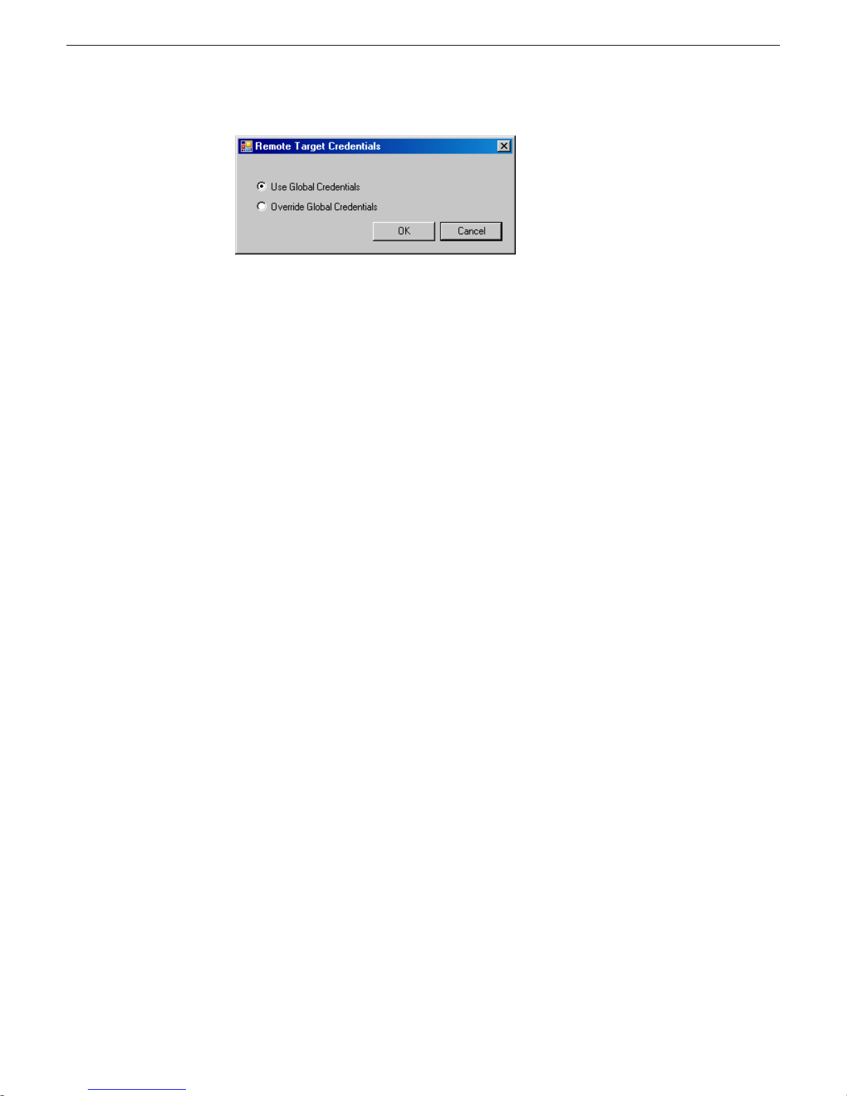
Configuring the network
2. Proceed as follows:
• If you previously applied credentials to the device that were different than the
global credentials and now you want to apply the global device type credentials,
select Use Global Credentials.
• If you want to apply credentials to the device that are different than the
device-type credentials, select Override Global Credentials.
The Set Device Logon Credentials dialog box opens.
3. Enter the user name and password for the device and click OK. To test the
credentials, right-click on the device and choose Remote Desktop to start a session
to the device.
Making the host name the same as the device name
1. Verify that the current device name, as displayed in the SiteConfig tree view, is
the same as your desired host name.
2. In the Network Configuration | Devices | Device list view, right-click the device and
select Edit.
The Edit Device dialog box opens.
3. If the host name is currently different than the device name, click Set to Device
Name.
This changes the host name to be the same as the device name.
4. Click OK.
Pinging devices from the control point PC
You can send the ping command to one or more devices in the system description
over the network to which the control point PC is connected. Typically this is the
control network.
1. In the Network Configuration | Networks tree view, select a network, site, or system
node.
4 October 2010 Aurora Edit Installation Guide 55
Page 56

Configuring the network
2. In the Devices list view, select one or more devices. Use Ctrl + Click or Shift +
3. Right-click the selected device or devices and select Ping.
The Ping Devices dialog box reports the progress and results of the ping command
per device.
About hosts files and SiteConfig
SiteConfig uses the network information in the system description to define a hosts
file and allows you to view the hosts file. SiteConfig can manage this hosts file on
Windows operating system devices that are in the system description and that are part
of a SiteConfig managed network.
When you have successfully assigned devices and applied planned network settings
to interfaces, it is an indication that host table information, as currently captured in
the system description, is valid and that you are ready to have SiteConfig assemble
the host table information into a hosts file. Your options for placing this host table
information on devices are as follows:
Click to select multiple devices.
The Ping Devices dialog box opens and lists the selected device or devices.
• If you do not want SiteConfig to manage your host table information, you can
manage it yourself. This is typically the case if your facility has an existing hosts
file that contains host table information for devices that are not in the SiteConfig
system description. In this case, you can have SiteConfig generate a single hosts
file that contains the host table information for the devices in the system description.
You can then copy the desired host table information out of the SiteConfig hosts
file and copy it into your facility hosts file. You must then distribute your facility
hosts file to devices using your own mechanisms.
• If you want SiteConfig to manage all information in hosts files on devices, you
can have SiteConfig copy its hosts file to devices. In so doing, SiteConfig overwrites
the existing hosts files on devices. Therefore, this requires that all devices that have
name resolution through the hosts file be configured accordingly in the SiteConfig
system description.
If you choose to have SiteConfig write hosts files to devices, the process consumes
system resource and network bandwidth. Therefore you should wait until you have
verified the information for all devices/interfaces in the host file, rather than updating
hosts files incrementally as you discover/assign devices.
SiteConfig does not automatically deploy hosts files to managed devices as you add
or remove devices. If you add or remove devices from the system description, you
must re-deploy the modified hosts file to all devices.
56 Aurora Edit Installation Guide 4 October 2010
Page 57

Generating host tables for devices with SiteConfig
Prerequisites for this task are as follows:
• Planned control network settings are applied to control network interfaces and
devices are communicating on the control network as defined in the system
description.
• Interfaces for networks that require name resolution via the hosts file, such as the
FTP/streaming network, have settings applied and are communicating.
• You have viewed host names, as currently defined in the system description, and
determined that they are correct.
• The control point PC is added to the system description so that it is included in the
host tables generated by SiteConfig.
1. In the Network Configuration | Networks tree view, select a network, site, or system
node.
2. Click View Hosts file.
A Hosts File Contents window opens that displays the contents of the hosts file
as currently defined in the system description.
3. Verify the information in the hosts file.
4. Do one of the following:
Configuring the network
• If you are managing host table information yourself, click Save As and save a
copy of the hosts file to a location on the control point PC. Then open the copy
of the hosts file, copy the desired host table information from it, and paste it
into your facility hosts file as desired. Then you can use your own process to
distribute the facility hosts file to devices. Remember to distribute to the control
point PC so that SiteConfig and other management applications such as
K2Config can resolve network host names.
• If SiteConfig is managing hosts files, do the following:
NOTE: Writing hosts files to multiple devices consumes system resource and
network bandwidth. Therefore it is recommended that you wait and do this
after the system is complete and fully implemented, rather than updating hosts
files incrementally as you discover/assign devices.
a) In the Network Configuration | Devices | Devices list view, right-click a device
to which you intend to write the hosts file and select View Current Host File.
A Host File Contents window opens that displays the contents of the hosts
file that is currently on that actual device.
b) Verify that there is no information that you want to retain in the device’s current
hosts file that is not also in the hosts file as currently defined in the system
description. If you need to save the device's current hosts file, click Save As
and save to a different location.
c) In the Network Configuration | Devices | Devices list view, right-click a device
or use Ctrl + Click to select multiple devices, and select Update Host File.
4 October 2010 Aurora Edit Installation Guide 57
Page 58
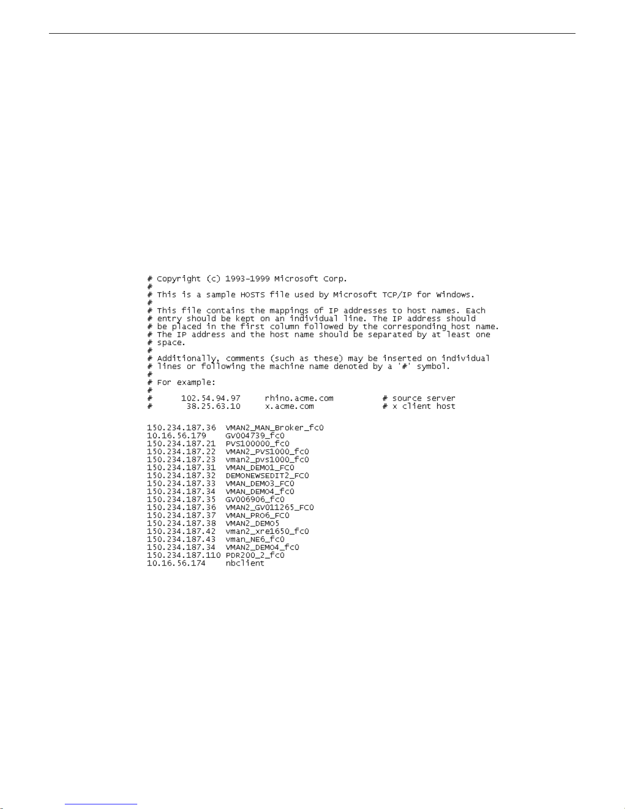
Configuring the network
Setting Up the Host Table
The host table is a file that resides on the Aurora Edit workstation, which resolves the
name of each Aurora Edit workstation with its IP addresses. Aurora Edit uses this file
to verify that clips are sent across the proper network.
Use this topic if you choose to manage your hosts files manually.
A sample hosts file looks like this:
The current hosts file is overwritten with the hosts file as defined in the
system description.
To set up a hosts file, do the following:
1. Open the following file using Notepad, or some other text editor:
C:\WINNT\System 32\Drivers\etc\hosts
2. Enter text in a single line for each Aurora Edit workstation and K2 server on your
network, as follows:
Type the IP address, then use the TAB key or Space bar to insert a few spaces.
Then type the device name, such as AuroraEdit1 followed by the characters
_FC0 for Fibre Channel or _HE0 for Gigabit Ethernet.
3. Save the file and close the text editor.
58 Aurora Edit Installation Guide 4 October 2010
Page 59

4. Copy the new hosts file onto all other Aurora Edit workstations.
Configuring the network
4 October 2010 Aurora Edit Installation Guide 59
Page 60

Page 61

Chapter 4
Managing Software
This section contains the following topics:
• Create record of software installed on devices
• Adding a software role to a device
• Removing a software role from a device
• Configuring deployment groups
• Distribute devices into deployment groups
• Install prerequisite files on the control point PC
• Prepare for installation
• Prepare SiteConfig for software deployment
• Upgrade K2 systems
• Set up K2 Aurora FTP
• Distribute devices into deployment groups
• Manually install software
• Check all currently installed software
• Add software package to deployment group
• Setting deployment options
• Install and configure software on a NewsShare System
• Install software on other Aurora Edit devices
4 October 2010 Aurora Edit Installation Guide 61
Page 62

Managing Software
Create record of software installed on devices
If you have not already done so, create a document to keep track of the software that
you plan to install on each of your system devices, according to your system design.
This is especially helpful for Aurora product devices. The following table is an example
of this type of document. Then, as you proceed with subsequent tasks and remove/add
software roles to devices in SiteConfig, you can refer to your table and make sure you
are assigning software roles correctly.
FTP-1HDK2-1FSM-1ING-1DSM-1EDIT-1CONF-1HD-1, 2, 3SVR-1Software
XMF Server
X+ K2 MDI
X+ News MDI
X+ NTFS
X+ FlashNET MDI
X+ Proxy MDI
+ RMI core
X+ FTP MDI
XAurora Browse
XProxy Encoder
XNews Share
XConform
XAurora Suite
X+ Edit
X+ Edit LD
XX+ FTP
X+ SmartBins
XAurora Ingest
XAurora Playout
XXXXXK2 - Gen iSCSI
XXXXXXK2 - GVG MLib
XK2 - Server
62 Aurora Edit Installation Guide 4 October 2010
XK2 - Client
XControl Point
XXXXXXXStorNext
Page 63
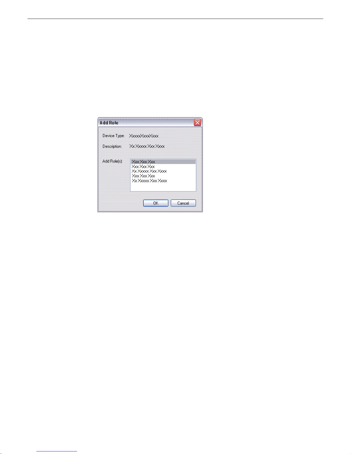
Adding a software role to a device
1. In the Software Deployment | Devices tree view, right-click the device and select
Add Role.
The Add Role dialog box opens.
Managing Software
The Add Role dialog box displays only those roles that SiteConfig allows for
the selected device type.
2. Select the role or roles that you want to add to the device. Use Ctrl + Click or Shift
+ Click to add multiple roles.
3. Click OK to save settings and close.
The new role or roles appear under the device in the tree view.
Removing a software role from a device
1. In the Software Deployment | Devices tree view, expand a device’s node to expose
the roles currently assigned to the device.
2. Right-click the role you want to remove and select Remove.
The role is removed from the device in the tree view.
Configuring deployment groups
Prerequisites for this procedure are as follows:
• The device is assigned in the SiteConfig system description and network
connectivity is present.
4 October 2010 Aurora Edit Installation Guide 63
Page 64
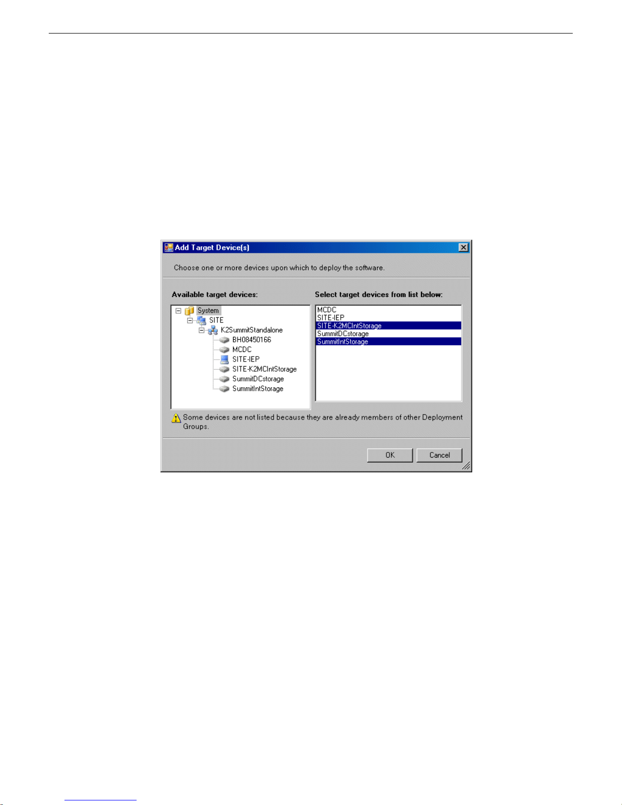
Managing Software
1. In the Software Deployment | Deployment Groups tree view, right-click the top node
and select Add Deployment Group.
A deployment group appears in the tree view.
2. Right-click the deployment group, select Rename, and enter a name for the
deployment group.
3. Right-click the deployment group and select Add Target Device.
The Add Target Device(s) wizard opens.
4. In the Available Target Devices tree view, select the node that displays the devices
that you are combining as a deployment group.
5. In the right-hand pane, select the devices that you are combining as a deployment
group.
To select multiple devices, you can drag through the devices, use Ctrl + Click,
or use Shift + Click.
6. Click OK.
The devices appear in the Deployment Groups tree view under the deployment group.
Before you perform a software deployment, you must check software on the devices
that will be receiving new software. If you have already added packages to the group,
on the Deployment Groups tab you will also see deployment tasks generated for every
device with roles that match the package contents.
64 Aurora Edit Installation Guide 4 October 2010
Page 65

Distribute devices into deployment groups
You can gather devices of different types into a SiteConfig deployment group. This
allows you to deploy software to all the devices in the deployment group at the same
time, as part of the same deployment session. Based on the roles you have assigned
to the devices, SiteConfig deploys the proper software to each device. This increases
the efficiency of your software deployment with SiteConfig.
If you have not already done so, configure your deployment groups. The recommended
deployment group distribution is as follows. Depending on your system design, your
system might not have all the device types listed.
• In a deployment group named "Aurora_Edit_Ingest_Playout", place the following
devices:
• Aurora Edit workstation of any storage options: Shared storage, NAS storage,
and stand-alone.
• Aurora Edit LD computer
• DSM
• Conform Server
• SmartBin Server
• FTP Server
• Aurora Ingest Platform
• IEP
• Aurora Playout Platform
Managing Software
• In a deployment group named "Aurora_Browse_MediaFrame", place the following
devices:
• MediaFrame server
• MDI server
• Aurora Proxy Encoder
• K2 Basecamp Express
• If you have a K2 Nearline SAN (NAS), in a deployment group named for the SAN
system, place the following devices:
• The Nearline SAN's K2 Media Servers.
Install prerequisite files on the control point PC
Some software components, such as those for Aurora products, share common
prerequisite software. You must install a prerequisite software package on the control
point PC to make the prerequisite software available for software deployment to
devices.
4 October 2010 Aurora Edit Installation Guide 65
Page 66

Managing Software
Prepare for installation
1. Check release notes for the required version of prerequisite files, if any.
2. On the SiteConfig control point PC, open Windows Add/Remove programs and
look for Grass Valley Prerequisite Files, then proceed as follows:
• If the required version of prerequisite files is installed, do not proceed with this
task.
• If prerequisite files are not installed or are not at the required version, proceed
with this task.
3. Procure the required prerequisite software installation file. The file name is
Prerequisite Files.msi.
4. On the SiteConfig control point PC, run the installation file. The installation program
copies prerequisite files to C:\Program Files\Grass Valley\Prerequisite
Files.
Before installing software, do the following:
• Procure the software installation files for this release via the appropriate distribution
method, such as download, CD-ROM, network drive, or external drive.
• Start up the devices on which you are installing software, if they are not already
started.
• Stop all media access on the devices on which you are installing software.
• Shut down all applications on the devices on which you are installing software.
Prepare SiteConfig for software deployment
1. Make the following files accessible to the SiteConfig control point PC:
• AuroraSuite software installation (*.cab) file
• AuroraEditLD software installation (*.cab) file
• NewsShare software installation (*.cab) file
• ConformServer software installation (*.cab) file
• Generic iSCSI software installation (*.cab) files
• GVGMLib software installation (*.cab) file
• PCmonitoring software installation (*.cab) file
2. If a newer version of SiteConfig is available for upgrade and you have not yet
upgraded SiteConfig, do the following:
a) From Windows Add/Remove programs, uninstall the current version of
SiteConfig from the control point PC.
b) Install the new version of SiteConfig on the control point PC.
66 Aurora Edit Installation Guide 4 October 2010
Page 67
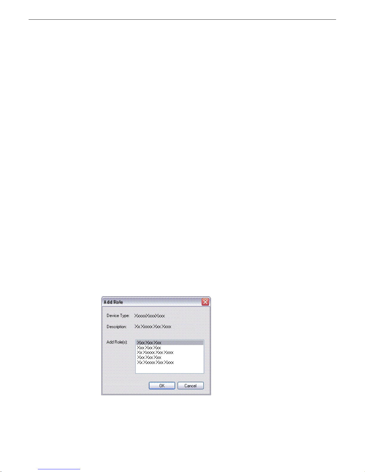
Upgrade K2 systems
Prerequisites for this task are as follows:
• If upgrading a K2 SAN, all SAN clients must be offline (all media access stopped)
or shut down. Depending on your system design, this could include devices such
as K2 clients, K2 appliances, Aurora Proxy (Advanced) Encoders, MDI server,
Aurora Edit clients, Aurora Ingest clients, Aurora Playout clients, and generic
clients.
Upgrade your K2 systems to the compatible version of K2 system software. This
includes K2 SAN systems and stand-alone K2 Media Client and K2 Summit
Production Client systems. Refer to K2 Release Notes for procedures.
Set up K2 Aurora FTP
Do the following tasks if you use K2-Aurora FTP.
Managing Software
Adding K2-Aurora FTP software role to K2 Media Server
Use the following SiteConfig procedure to add the K2-Aurora FTP role to the K2 Media
Server that you use as your K2-Aurora FTP server, if you have not already done so.
The K2 Media Server that you use as your K2-Aurora FTP server must also have the
role of K2 FTP Server.
1. In the Software Deployment | Devices tree view, right-click the device and select
Add Role.
The Add Role dialog box opens.
4 October 2010 Aurora Edit Installation Guide 67
Page 68
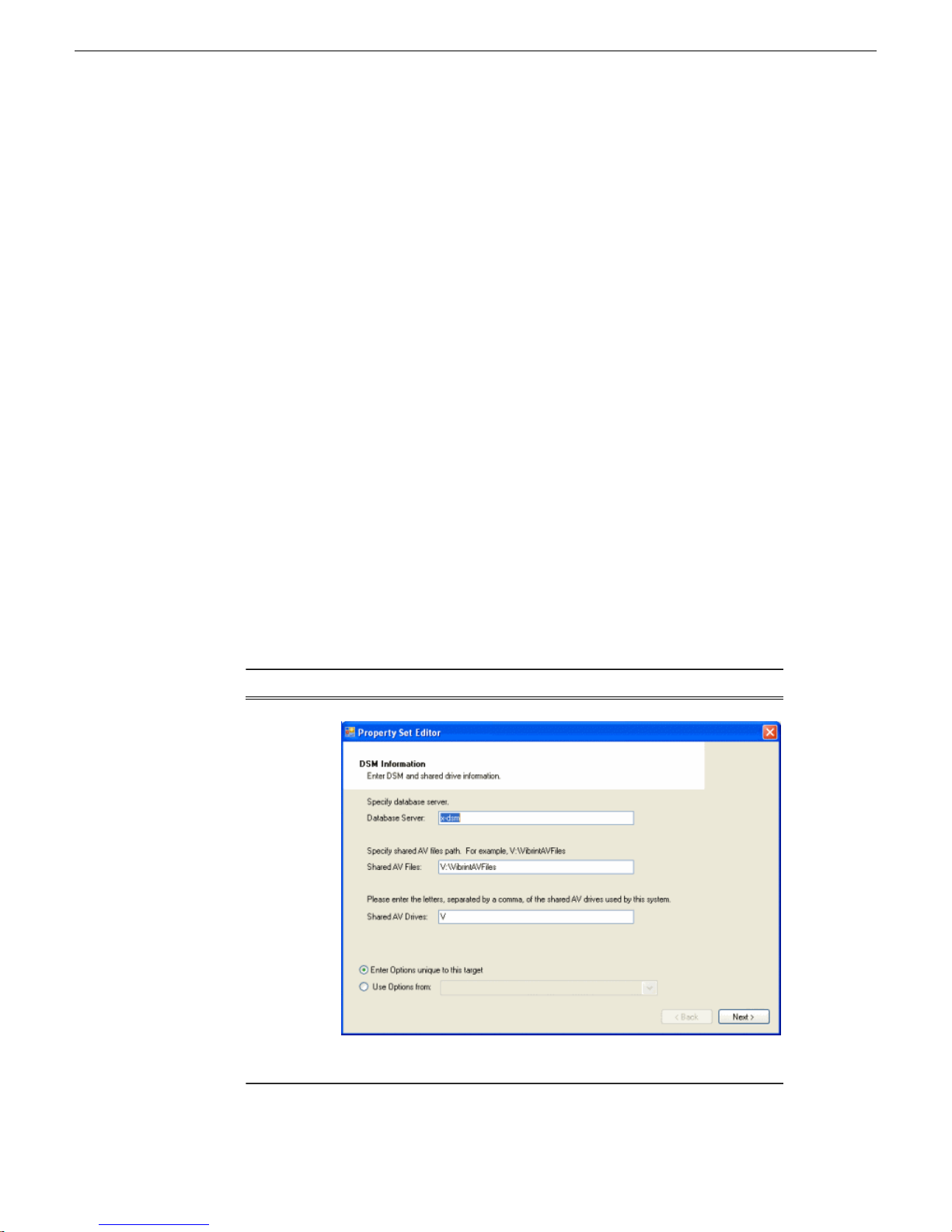
Managing Software
Install and configure K2-Aurora FTP
The Add Role dialog box displays only those roles that SiteConfig allows for
the selected device type.
2. Select the role or roles that you want to add to the device. Use Ctrl + Click or Shift
+ Click to add multiple roles.
3. Click OK to save settings and close.
The new role or roles appear under the device in the tree view.
1. In SiteConfig, check software on the the deployment group that contains your K2
Media Servers.
2. In SiteConfig, add the K2AuroraFTP_x.x.x.xxx.cab file to the deployment group
that contains your K2 Media Servers.
3. Proceed with next steps to set deployment options for K2-Aurora FTP software.
4. Do one of the following to set deployment options:
• Double-click the task.
• Select the task and click the Options button.
A wizard opens.
5. Work through the wizard and set deployment options as follows:
Software
K2-Aurora
FTP
Deployment options
68 Aurora Edit Installation Guide 4 October 2010
Enter Database server(DSM), Shared AV Files, Shared AV Drives.
Page 69
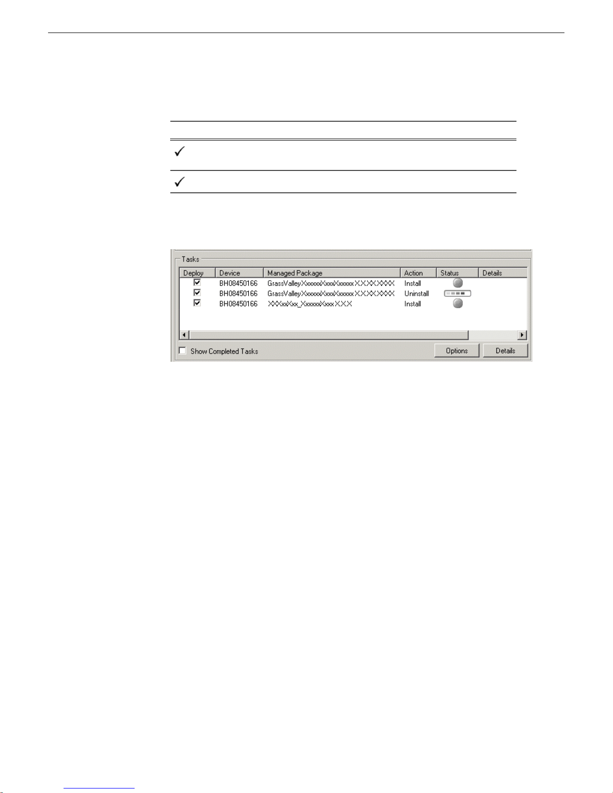
6. Deploy the following tasks:
Managing Software
Managed PackageDeploy
K2-Aurora FTP x.x.x.xxx
Action
Uninstall (if upgrading K2-Aurora
FTP)
InstallK2-Aurora FTP x.x.x.xxx
7. Click the Start Deployment button.
8. When the Status or Details columns indicate next steps, identify the software in
the row, then do one of the following:
• For K2 software, when Details displays a Restart required link, click the link
and when prompted "...are you sure...", click Yes.
• If the Details column does not prompt you, restart the K2 Media Server manually.
The K2 Media Server restarts. This restart is required.
9. On the K2 Media Server, to enable port range limits for passive transfers, create
the following two DWORDs in the registry at
HKEY_LOCAL_MACHINE/SOFTWARE/Grass Valley Group/Streaming/:
• FtpPasvStart (starting port number, inclusive : DWORD)
• FtpPasvEnd (ending port number, inclusive : DWORD)
10. Open MediaFrame Configuration and for the News MDI, configure the transfer
server to the K2 Media Server that is your K2-Aurora FTP server.
Distribute devices into deployment groups
You can gather devices of different types into a SiteConfig deployment group. This
allows you to deploy software to all the devices in the deployment group at the same
time, as part of the same deployment session. Based on the roles you have assigned
4 October 2010 Aurora Edit Installation Guide 69
Page 70

Managing Software
to the devices, SiteConfig deploys the proper software to each device. This increases
the efficiency of your software deployment with SiteConfig.
If you have not already done so, configure your deployment groups. The recommended
deployment group distribution is as follows. Depending on your system design, your
system might not have all the device types listed.
• In a deployment group named "Aurora_Edit_Ingest_Playout", place the following
devices:
• Aurora Edit workstation of any storage options: Shared storage, NAS storage,
and stand-alone.
• Aurora Edit LD computer
• DSM
• Conform Server
• SmartBin Server
• FTP Server
• Aurora Ingest Platform
• IEP
• Aurora Playout Platform
• In a deployment group named "Aurora_Browse_MediaFrame", place the following
devices:
• MediaFrame server
• MDI server
• Aurora Proxy Encoder
• K2 Basecamp Express
• If you have a K2 Nearline SAN (NAS), in a deployment group named for the SAN
system, place the following devices:
• The Nearline SAN's K2 Media Servers.
Manually install software
Some tasks that might be required are not supported for SiteConfig management and/or
software deployment. For these tasks you must manually install and/or configure
before using SiteConfig to install software. Refer to the tasks in this section as
appropriate for your system.
Install Microsoft SQL Server 2005 Standard Edition
Microsoft SQL Server 2005 Standard Edition is installed on devices as follows:
• Aurora DSM – SQL Server 2005 Standard Edition is required.
70 Aurora Edit Installation Guide 4 October 2010
Page 71

Use the following steps to manage Microsoft SQL Server 2005 Standard Edition.
Determine if you have Microsoft SQL Server 2005 Standard Edition installed and
then do one of the following:
• If installed, check version compatibility information in release notes and if an
upgrade is required, go to the local device and upgrade Microsoft SQL Server
2005 Standard Edition.
• If not installed, install Microsoft SQL Server 2005 Standard Edition as directed
by the Microsoft product documentation.
Configuring SQL Server
SQL server software must be installed on the DSM (Data System Manager) using the
procedure given below.
1. Select Start | Programs | Microsoft SQL Server | Enterprise Manager.
2. Expand the Tree view to reveal the DSM machine by clicking the “+” next to
“Microsoft SQL Servers” and also next to “SQL Server Group.”
3. Right click on the DSM icon and select Properties. (Except as noted in the following
steps, do not change default values.)
4. Click the Security tab. Under Authentication, make sure that SQL Server and
Windows is selected.
5. Click the Memory tab and verify that Dynamically configure SQL Server memory
is selected. Set the memory limit to 256 MB less than the server’s memory size.
6. Click OK to save settings and close the SQL Server Properties dialog box.
Managing Software
Check all currently installed software
Prerequisites for this task are as follow:
• The device is assigned in the SiteConfig system description and network
connectivity is present.
• SiteConfig is able to log in to the device using the username/password credentials
assigned to the device.
• The SiteConfig control point PC does not have a network drive mapped to an
administrative share (such as C$) on a device on which you are checking software.
• If the SiteConfig Network Configuration Kit and/or Discovery Agent at version
lower than 1.1.0.185 is currently installed, it must be manually uninstalled and
updated. For more information refer to SiteConfig Migration Instructions.
• If Aurora product software at a version lower than 6.5.2 is currently installed, it
must be manually uninstalled. For more information refer to SiteConfig Migration
Instructions.
Do the following steps on the devices on which you are installing software.
4 October 2010 Aurora Edit Installation Guide 71
Page 72

Managing Software
1. In the Software Deployment | Deployment Groups tree view, right-click the top-most
node for the group or any individual device and select Check Software.
NOTE: If you have access problems, verify that the adminstrator account on
the device has credentials as currently configured in SiteConfig. By default
credentials on the device should be administrator/adminGV! for Aurora devices
and Administrator/adminK2 for K2 devices.
The Check Software dialog box appears. SiteConfig searches for software on
the selected device or devices and gathers information. Progress is reported.
2. When the check is complete for the selected device or devices, close the Check
Software dialog box.
An updated list of all currently installed software is displayed in the Software
Deployment | Devices | Installed Software list view. If software is a SiteConfig managed
software package, information is displayed in the Managed Package and Deployment
Group columns.
Add software package to deployment group
Prerequisites for this task are as follows:
• You can access the software package file from the SiteConfig control point PC.
• The devices to which you are deploying software are in a deployment group.
Use the following procedure to add one or more software package installation files to
the deployment group that contains the devices in the following list. Depending on
your system design, you might not have all of the device-types listed:
• Aurora Edit Workstation
• Aurora Edit LD computer
• DSM
• Conform Server
• SmartBin Server
• FTP Server
Identify and add software package installation files as follows:
File nameSoftware
AuroraSuite_x.x.xxx.cabAurora Suite
AuroraEditLD_x.x.xxx.cabAurora Edit LD
NewsShare_x.x.xxx.cabNewShare
agent
72 Aurora Edit Installation Guide 4 October 2010
ConformServer_x.x.xxx.cabConform server
PCMonitoring_x.x.xxx.cabGrass Valley Windows Monitoring SNMP
Page 73

Managing Software
Depending on the K2 software version of your K2 SAN, also add software package
installation files as follows:
NOTE: Add files for either 3.x OR 7.x. Do not add files for both 3.x AND 7.x.
• If your devices access storage on a K2 software version 3.x K2 SAN, add software
package installation files as follows:
File nameSoftware compatible with 3.x K2 SAN
GenericISCI_x86_3.x.xxx.cabGeneric iSCSI client for 32 bit systems
GVG_MLib_3.x.xxx.cabGVG MLib
SNFS is bundled with the Generic iSCSI cab file.
• If your devices access storage on a K2 software version 7.x K2 SAN, add software
package installation files as follows:
File nameSoftware compatible with 7.x K2 SAN
GenericISCI_x86_7.x.xxx.cabGeneric iSCSI client for 32 bit systems
GVG_MLib_7.x.xxx.cabGVG MLib
1. In the Software Deployment | Deployment Groups tree view, select a deployment
group.
2. Click the Add button.
The Add Package(s) dialog box opens.
3. Do one of the following to select the software package:
• Select from the list of packages then click OK.
• Click Browse, browse to and select the package, then click Open.
4. If one or more EULAs are displayed, accept them to proceed. If you do not accept
a EULA, the associated software is not assigned to the deployment group.
SiteConfig adds the package to the deployment group.
The package appears in the Managed Packages list for the selected deployment group.
SiteConfig creates new software deployment tasks for the package and displays them
in the Tasks list view.
Setting deployment options
Pre-requisites for this procedure are as follows:
• A software package has been assigned to the deployment group and applicable
deployment tasks are now displayed in the Tasks area.
1. In the Software Deployment | Deployment Groups tree view, select a deployment
group.
4 October 2010 Aurora Edit Installation Guide 73
Page 74
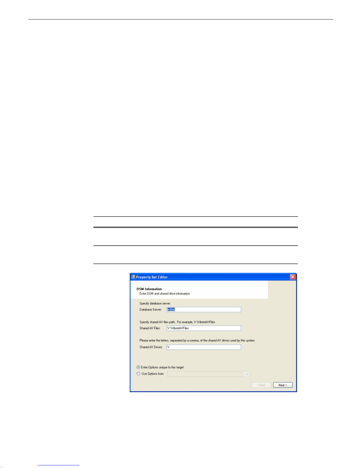
Managing Software
2. In the Tasks list view, view tasks and determine if you must set deployment options.
Tasks that need to have deployment options set display in the Details column a
message stating "Deployment options required."
If you select a task that needs to have its deployment options set, the Start
Deployment button is disabled and the message is displayed next to the button.
3. Proceed with next steps to set deployment options for the following:
• GVG_MLib
• Conform Server
• Aurora Edit LD
4. Do one of the following to set deployment options:
• Double-click the task.
• Select the task and click the Options button.
A wizard opens.
5. Work through wizards and set deployment options as follows:
Software
GVG_MLib
Conform
Server
Aurora
Suite
Deployment options
Enter the name(s) of the K2 Media Server(s) with role of file system
server (FSMs)
Database server, Shared AV Files (e.g. V:\xreAVFiles), Shared AV
Drives, and the Media Frame Server
74 Aurora Edit Installation Guide 4 October 2010
Enter Database server(DSM), Shared AV Files, Shared AV Drives.
Page 75
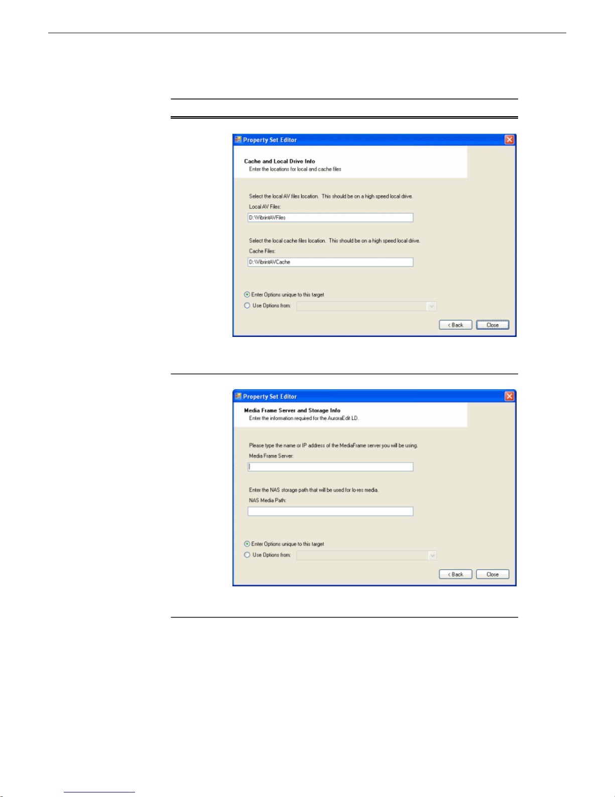
Managing Software
Software
Aurora Edit
LD
Deployment options
Enter Local AV Files, Cache Files.
6. If you have multiple devices of the same type, you can enter deployment options
for one of them using the wizard. Then, when you bring up the same wizard on
every device, you can choose the Use options from radio button and select the first
device for which you set options.
4 October 2010 Aurora Edit Installation Guide 75
Enter MediaFrame Server and NAS Media Path.
Page 76

Managing Software
Install and configure software on a NewsShare System
SiteConfig copies the options you set for the first device and fills in the blanks
on the wizard.
Do not do these tasks if:
• You do not have any shared storage (NewsShare) Aurora Edit systems. Skip to the
later task to install software on other Aurora Edit devices.
Do these tasks if:
• You have shared storage (NewsShare) Aurora Edit Workstations.
• You have one or more Conform Servers.
• You have SmartBins that require access to the shared storage and the SmartBin
server that is not one of the above device.
You must install and configure software as instructed by the following tasks for these
Aurora Edit device types.
Prerequisites for these tasks are as follows:
• The devices to which you are deploying software are in a deployment group.
• Prerequisite files are installed on the control point PC.
• You have recently done the SiteConfig "Check Software" operation on the devices
to which you are deploying software.
For shared storage Aurora Edit devices, you must use a specific sequence of installation and
configuration tasks. The installation sequence is summarized as follows:
1. Install the software necessary for connection to shared storage on Aurora Edit
devices.
2. Map the storage volume one of the following ways:
• If NAS storage, mount the NAS volume on Aurora Edit devices.
• If K2 SAN storage, add all SAN connected devices to the SAN using K2 Config.
3. Install Aurora Suite software.
Use the following tasks to accomplish this sequence.
Install storage software on shared storage devices
1. In the Software Deployment | Deployment Groups tree view, select the device or the
group of devices to which you are deploying software.
The corresponding software deployment tasks are displayed in the Tasks list
view.
2. For the software you are installing, select the Deploy check box in the row for the
install task.
76 Aurora Edit Installation Guide 4 October 2010
Page 77
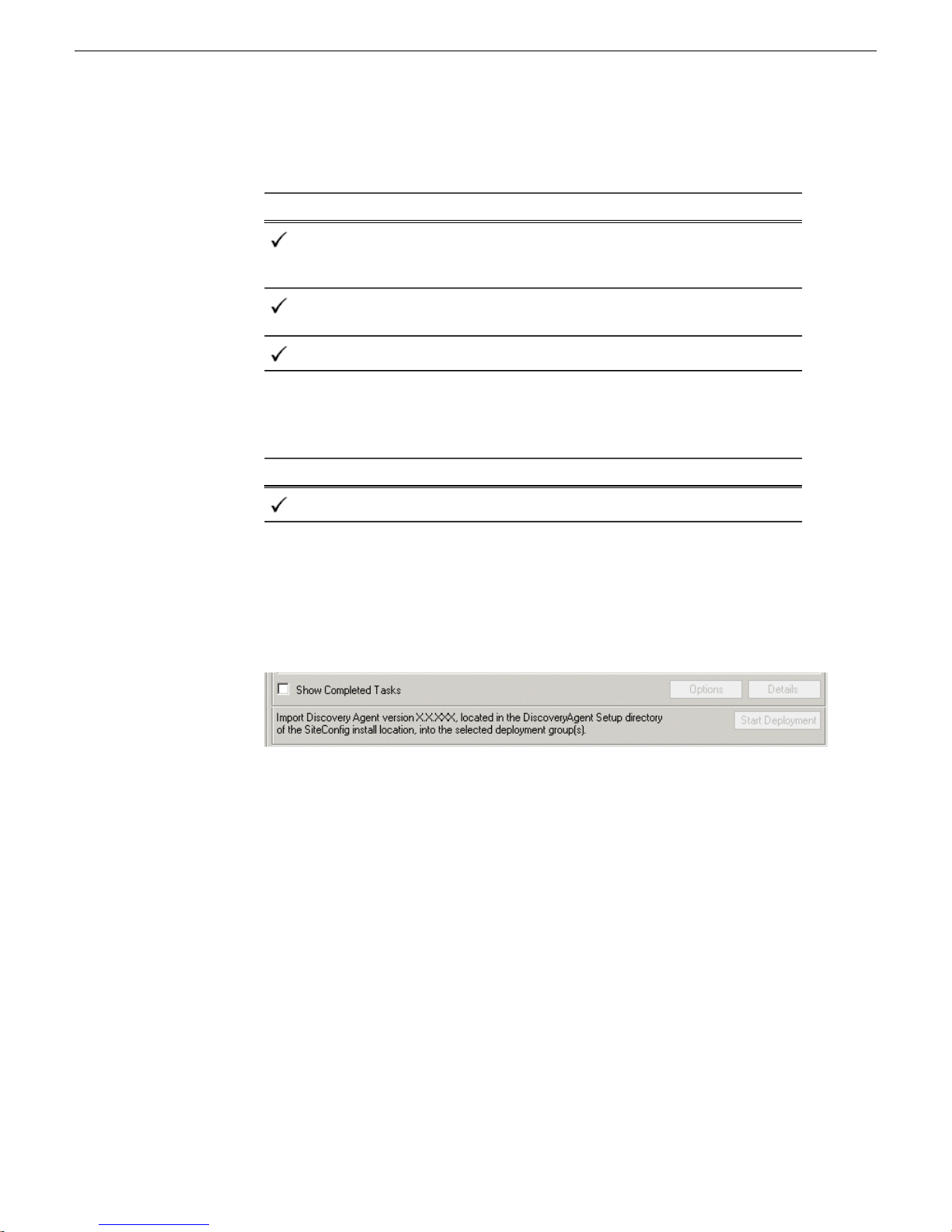
Install software as follows:
Managing Software
Managed PackageDeploy
GenericISCI x86 xxxx.xxxx
(version must be compatible with
K2 SAN)
must be compatible with K2 SAN)
Action
Install
InstallGVGMLib xxxx.xxxx (version
InstallPCmonitoring xxxx.xxxx
Also, you must install SNFS, so deploy the following tasks at the same time.
Make sure you install the version of SNFS that is compatible with your K2
systems.
Managed PackageDeploy
SNFS nonK2 x86 x.x.x.xxx
Action
Install
NOTE: If there are dependencies, SiteConfig can enforce that some tasks be
deployed together.
3. Check the area next to the Start Deployment button for a message.
If a message instructs you to upgrade the Discovery Agent, on the control point
PC go to the directory to which SiteConfig is installed, find the
DiscoveryAgent_x.x.x.x.cab file, add it to the deployment group, and deploy
the Discovery Agent software as well.
4. Click the Start Deployment button.
Deployment tasks run and software is installed. Progress is reported and next
steps are indicated in both the Status and Details columns.
5. When the Status or Details columns indicate next steps, identify the software in
the row, then do one of the following:
• When Details displays a Restart required link, click the link and when prompted
"...are you sure...", click Yes.
The device restarts.
4 October 2010 Aurora Edit Installation Guide 77
Page 78

Managing Software
Configuring devices for NAS
Next follow the task as appropriate to mount your shared storage, either NAS or K2
SAN storage.
For each client machine and the Conform Server running the SmartBin Service, if
applicable, you need to mount the NAS volume before installing the Aurora Suite
software. In addition, if the client machines are used by more than one user login, you
need to log in under each user account and mount the NAS volume.
Prerequisites for this task are as follows:
• GVMLib software is installed on the Aurora Edit devices.
1. On the machine you want to map the drive to, open My Computer and select Tools
| Map Network Drive.
2. Select the NAS drive.
3. Type in the name of the NAS folder where the shared database resides.
4. Check the Reconnect at login checkbox.
5. Click Finish.
Configuring devices for K2 SAN storage
This section describes configuring devices to interface to K2 SAN storage.
Prerequisites for this task are as follows:
• Generic iSCSI, GVMLib, and SNFS software is installed on SAN connected
devices.
1. Following the instructions in the K2 SAN Installation and Configuration Manual,
do the following, if not set up already:
a) Set up the Control Point PC.
b) Run the K2 Config application to set up the K2 Server and Gigabit Ethernet
switch.
c) Connect all SAN clients to the K2 Server via the Gigabit Ethernet switch.
2. Use K2 Config to configure each device as a generic iSCSI client.
Given the bandwidth that a client workstation is expected to use, the K2 network
can load balance workstations’ iSCSI connections to the K2 storage system.
You can estimate the required bandwidth using the following formula: (Video
Bit Rate in Mbps x Number of Streams) / 8.
a) Determine the highest bit rate you use on the Aurora Edit device.
DV rates for NTSC and PAL are 28.8 Mbps for DV25, 57.6 Mbps for DV50,
and 115.2 Mbps for DV100. MPEG bit rates are variable; use the configured
bit rate.
78 Aurora Edit Installation Guide 4 October 2010
Page 79

b) Multiply the highest bit rate by the number of streams that are licensed on the
workstation.
c) Divide that number by 8 to and round to the nearest integer to convert Mbps to
MB.
d) Use the final MB number in the K2 Configuration wizard’s iSCSI Client
Bandwidth Input screen.
See the K2 documentation for complete instructions.
Install Aurora software on shared storage devices
Prerequisites for this task are as follows:
• Generic iSCSI, GVMLib, and SNFS software is installed on the devices.
• The shared storage is mounted on the devices.
• On a Conform Server, if you are using a Fibre Channel card, verify that the IP
MTU uses the same setting as other Aurora Edit clients.
1. In the Software Deployment | Deployment Groups tree view, select the device or the
group of devices to which you are deploying software.
Managing Software
The corresponding software deployment tasks are displayed in the Tasks list
view.
2. For the software you are installing, select the Deploy check box in the row for the
install task.
Install Aurora software as follows:
Managed PackageDeploy
Action
InstallAuroraSuite x.x.x.xxx
InstallConformServer x.x.x.xxx
InstallNewsShare x.x.x.xxx
3. Click the Start Deployment button.
Deployment tasks run and software is uninstalled. Progress is reported and next
steps are indicated in both the Status and Details columns. If an error appears
regarding prerequisite software, install the prerequisite files on the control point
PC and then repeat this step.
4. When the Status or Details columns indicate next steps, identify the software in
the row, then do one of the following:
• If Details displays a visible dialog pending link, continue with this procedure.
4 October 2010 Aurora Edit Installation Guide 79
Page 80
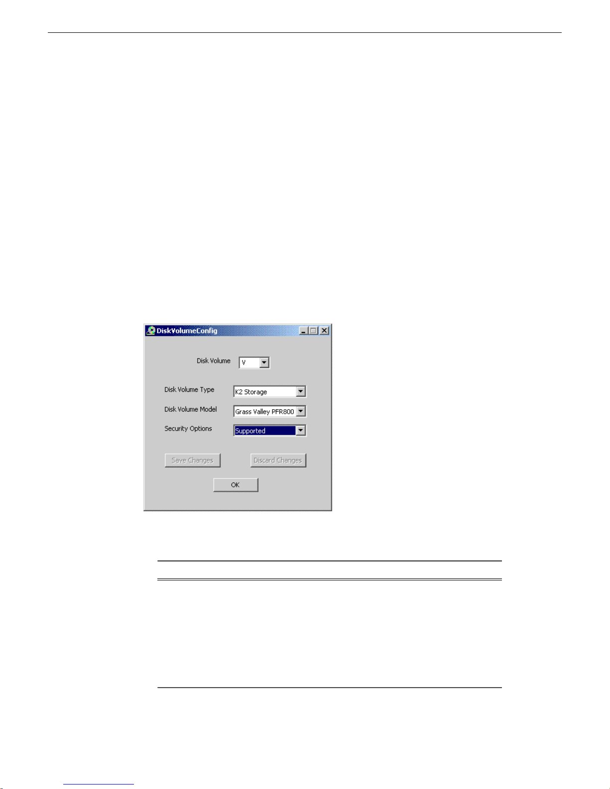
Managing Software
Configuring the Disk Volume
5. Remote in to the machine and enter the appropriate information, as instructed in
the next task. Once the dialog is dismissed SiteConfig continues with the install.
When you install Aurora Edit software for the first time, you must configure a shared
volume for your type of network and equipment wherever the AuroraSuite installer
is run. The Disk Volume Configuration only needs to be done once on each shared
volume, on the first Aurora Edit system on which the software is installed.
Prerequisites for this task are as follows:
• Generic iSCSI, GVMLib, and SNFS software is installed on the Aurora Edit
workstations.
• The shared storage is mounted on the Aurora Edit workstations.
• The installation process for Aurora Suite software is underway.
To configure the disk volume refer to the illustration and table below:
1. Select the disk volume drive letter in the pulldown and configure the volume as
follows:
Disk
Volume
Type
80 Aurora Edit Installation Guide 4 October 2010
OptionsSetting
Unknown
LocalDisk
NAS
K2 Storage
Open SAN
Description
Select your type of shared storage.
Page 81

Managing Software
Description
NAS:Unknown
Choose Ciprico 1700, 2400, 3600, or
IBM NAS.
Disk
Volume
Model
OptionsSetting
Grass Valley PFR500,
PFR600, PFR700, PFR800
K2 Storage:Ciprico 1700, 2400, 3600
Security
Options
IBM NAS
Supported
Not Supported
Choose Grass Valley PFR700.
Select Supported if your system uses
Domain Security; otherwise, select Not
Supported.
2. Click OK to save changes and return to the software installer.
When installing Aurora Suite using SiteConfig, continue with the following
steps.
3. When the Status or Details columns indicate next steps, identify the software in
the row, then do one of the following:
• When Details displays a Restart required link, click the link and when prompted
"...are you sure...", click Yes.
The device restarts.
Install software on other Aurora Edit devices
Do not do this task if:
• You are install software on shared storage (NewsShare) Aurora Edit workstations.
Use the previous task instead.
Do this task if:
• You are installing software on the following types of the devices:
• Stand-alone Aurora Edit workstation
• Aurora Edit LD computer
• DSM
• SmartBin Server
• FTP Server
Prerequisites for this task are as follows:
• The devices to which you are deploying software are in a deployment group.
• Prerequisite files are installed on the control point PC.
4 October 2010 Aurora Edit Installation Guide 81
Page 82

Managing Software
• You have recently done the SiteConfig "Check Software" operation on the devices
to which you are deploying software.
1. In the Software Deployment | Deployment Groups tree view, select the device or the
group of devices to which you are deploying software.
The corresponding software deployment tasks are displayed in the Tasks list
view.
2. For the software you are deploying, select the Deploy check box in the row for the
uninstall task.
NOTE: If you manually uninstalled or installed software, the uninstall task
might not appear or it might appear with a different package name.
3. For the software you are installing, select the Deploy check box in the row for the
install task.
For installing software on Aurora Edit devices, deploy the following tasks:
Managed PackageDeploy
must be compatible with K2 SAN)
Managed PackageDeploy
SNFS nonK2 x86 xxxx.xxxx
(version must be compatible with
K2 SAN)
Action
InstallAuroraSuite x.x.x.xxx
InstallAuroraEditLD x.x.x.xxx
InstallNewsShare x.x.x.xxx
InstallGVGMLib xxxx.xxxx (version
InstallPCmonitoring x.x.x.xxx
Action
Install
NOTE: If there are dependencies, SiteConfig can enforce that some tasks be
deployed together.
4. Check the area next to the Start Deployment button for a message.
82 Aurora Edit Installation Guide 4 October 2010
Page 83
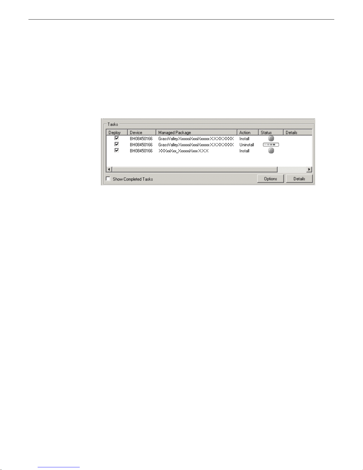
Managing Software
If a message instructs you to upgrade the Discovery Agent, on the control point
PC go to the directory to which SiteConfig is installed, find the
DiscoveryAgent_x.x.x.x.cab file, add it to the deployment group, and deploy
the Discovery Agent software as well.
5. Click the Start Deployment button.
Deployment tasks run and software is installed. Progress is reported and next
steps are indicated in both the Status and Details columns.
6. When the Status or Details columns indicate next steps, identify the software in
the row, then do one of the following:
• For K2 software, when Details displays a Restart required link, click the link
and when prompted "...are you sure...", click Yes.
7. Monitor progress as indicated by both the Status and Details column. When finished,
the Status column indicates complete.
4 October 2010 Aurora Edit Installation Guide 83
Page 84

Page 85

Chapter 5
Manually Installing Aurora Edit and LD
Software
This section contains the following topics:
• Manually Installing Aurora Edit/Aurora Edit LD Software
• Third Party Software Installation
4 October 2010 Aurora Edit Installation Guide 85
Page 86

Manually Installing Aurora Edit and LD Software
Manually Installing Aurora Edit/Aurora Edit LD Software
If you are not using SiteConfig to install software, this section describes the steps to
install the Aurora Edit and Aurora Edit LD applications manually.
The Aurora Edit software is available on the CD included with the application.
1. Uninstall any previous version of Aurora Edit software using the Windows Add or
Remove Programs program in Start/Settings/Control Panel.
2. Find the AuroraSetup directory on the CD provided and double-click on Setup.exe.
Wait for the Aurora Suite Installation Wizard to appear.
3. When the Welcome screen appears, select Next>.
4. Review the License agreement and click I accept the license agreement and Next>.
5. Click the X next to Aurora Edit or Aurora Edit LD and select Entire feature will be
installed on local hard drive.
Click Next>.
6. If you are installing a local Aurora Edit workstation, select Local and click Next>.
For a Local install, skip to step 13.
7. If you are installing a shared Aurora Edit or Aurora Edit LD, select Shared and
click Next>.
In the Select Shared Server field, enter the name of the database server that you
are using for the Shared database and select Next>.
8. In the Select Shared AV Files Directory, select the directory where the Aurora Suite
Video and Audio files are to be saved. This should be a directory located on a high
speed AV disk drive.
Click Next> to accept the default directory, V:\VibrintAVFiles or select the main
shared AV files location you plan on using.
9. In the Select Local AV Files Directory, select the directory where the local Aurora
video and audio files are to be saved. This should be a directory located on a high
speed AV disk drive, on your local system.
Click Next> to accept the default D:\VibrintAVFiles.
10. In the Select AV Cache Files Directory, select the directory where the Aurora AV
Cache file are to be saved. This should be a directory located on a high speed AV
disk drive, on your local system.
Click Next> to accept the default D:\VibrintCache.
11. In the Select Shared Drives window, enter the letter drives, separated by a comma,
of the shared AV drives used by the system.
Select Next>.
86 Aurora Edit Installation Guide 4 October 2010
Page 87

12. For Aurora LD only, a MediaFrame Server Settings window will come up and ask
for the name or IP address of the MediaFrame server you will be using. You must
also enter the NAS Media Path for the NAS storage that will be used for media.
Select Next>.
13. Click Next> to install the application.
Wait for the install to completely finish. It will take a few minutes to complete.
Third Party Software Installation
Aurora Edit and Aurora Edit LD application interface with many third party products
that are manufactured by other vendors (ENPS for example). Many of these products
require installing plug-in or driver software. Refer to the Aurora Edit and Aurora Edit
LD Installation Manual for instructions on installing software for any third party
products. Many of these products may also include installation instructions. Be sure
to use these instructions for proper installation. Please note it is very important to
check the Compatible third party products software table in these release notes so you
use the validated software or driver version required for this release.
Manually Installing Aurora Edit and LD Software
4 October 2010 Aurora Edit Installation Guide 87
Page 88

Page 89

Chapter 6
Aurora Edit Application Configuration
This section contains the following topics:
• Setting Up Media Files for Sharing
• About Aurora Edit video sources
• Option Configurations
• Understanding the System Self-Test
4 October 2010 Aurora Edit Installation Guide 89
Page 90

Aurora Edit Application Configuration
Setting Up Media Files for Sharing
Before you can transfer media files to another Aurora Edit workstation, you need to
set up your workstation for sharing.
To share files:
1. In Windows Explorer, navigate to the drive where media files are stored (usually
D:\).
2. Right click on the VibrintAVFiles folder and choose Sharing.
3. Select the Shared As option and leave the default share name VibrintAVFiles.
Click OK.
The folder you shared appears with the standard Windows sharing icon.
About Aurora Edit video sources
Before using footage from a particular source, you need to add the source to the Aurora
Edit source list. Aurora Edit pre-installs two sources for you — a video source and a
clip source:
Video source
Clip source
Allows you to record footage directly into the Timeline or Bin; usually
a tape deck.
Allows you to edit a clip as a Timeline source directly in the Bin, which
is useful for large clips so you don’t have to go back and forth from a
tape deck. You only need one clip source; you don’t have to create a
new clip source for each clip you want to use
Add Source—General settings
Source Type
Video
Source
Clip Source
1394
Source
DescriptionOptionsSetting
Enter a name for the source, such as Tape Deck.Source Name
Enter a description for the source.Description
Select Video Source for all incoming sources, including
audio sources.
Select Clip Source to use an existing clip in the bin as a
source.
Select Microphone for any microphone sources.Microphone
Select 1394 Source when connecting to a specific 1394
source if multiple IEEE devices are present.
90 Aurora Edit Installation Guide 4 October 2010
Page 91

Add Source—Connections settings
The options available depend upon your Source Type setting on the General tab.
Aurora Edit Application Configuration
Video
Input
1394 Input
Audio
Input
Deck
Protocol
Composite
Component
SDI S-Video
(Y/C)
Name>
Balanced
Analog
AES/EBU
(BNC)
AES/EBU
(XLR)
SDI/Embedded
No remote
deck controls
DNW-A100
DV 1394
DescriptionOptionsSetting
Select the Video Input option that
corresponds to the source’s connection to
Aurora Edit.Composite is the default video
input.
Select the 1394 device you are using.Any <Device
Select the Audio Input option that
corresponds to the source’s connection to
Aurora Edit. Balanced Analog is the default
audio input.
Select the Deck Protocol that corresponds to
the type of tape deck control you are using
select No remote deck controls, which is the
default setting.
Source
Type
Video
Source Clip
Source
1394
Source
Video
Source Clip
Source
MicrophoneDefault setting for a Microphone Source.Mic Preamp
Video
Source Clip
Sourcewith Aurora Edit. If you are adding a clipSony 422
Microphonesource, video router, or a non-video source,Protocol Sony
1394
Source
Comm
Port
Input Latency
Number Loop Tones
None COM1 COM10
Select the Comm Port you are using to
connect the source to Aurora Edit.
Enter a duration to add an input latency when
using a 1394 converter.
exist between loop record takes; each second,
a tone plays through the system speakers.
Video
Source Clip
Source
Microphone
1394
Source
Video
Source Clip
Source
Microphone
1394
Source
MicrophoneEnter a duration to set how many seconds
4 October 2010 Aurora Edit Installation Guide 91
Page 92

Aurora Edit Application Configuration
Add Source—Record Channels settings
DescriptionOptionsSetting
Check Video if you want to record video with this source.Video
A1 to A8Channel 1
Audio
A1 to A8Channel 2
Audio
A1 to A8Channel 3
Audio
A1 to A8Channel 4
Audio
Check each audio channel that should record audio from this
source and select the default audio track (A1–A8) on the
Timeline to which you want the channel routed.
Setting up a microphone source that does not record video (audio-only record) greatly
reduces the required disk space.
Add Source—Record Handles settings
DescriptionSetting
In Handles Out
Handles
Enter the number of seconds for the In and Out Handle length.
Handles provide the extra frames necessary to trim or add transition
effects at the head or tail of a clip. When you Mark In and Mark Out,
Aurora Edit begins recording the specified number of seconds before
your Mark In and after your Mark Out. Only the material between
your marks is edited to the Timeline
Add Source—Preroll settings
DescriptionSetting
Get Preroll From
Deck
Preroll
Aux Preroll
92 Aurora Edit Installation Guide 4 October 2010
Check Get Preroll From Deck to use the preroll settings from your
tape deck instead those configured in Aurora Edit.
Enter the number of seconds of preroll to use when recording from
this source. This setting overrides the source’s Preroll setting unless
you check Get Preroll From Deck.
Enter the number of seconds of auxiliary preroll you want to use
when using an auxiliary input or a non-remote source.
Page 93
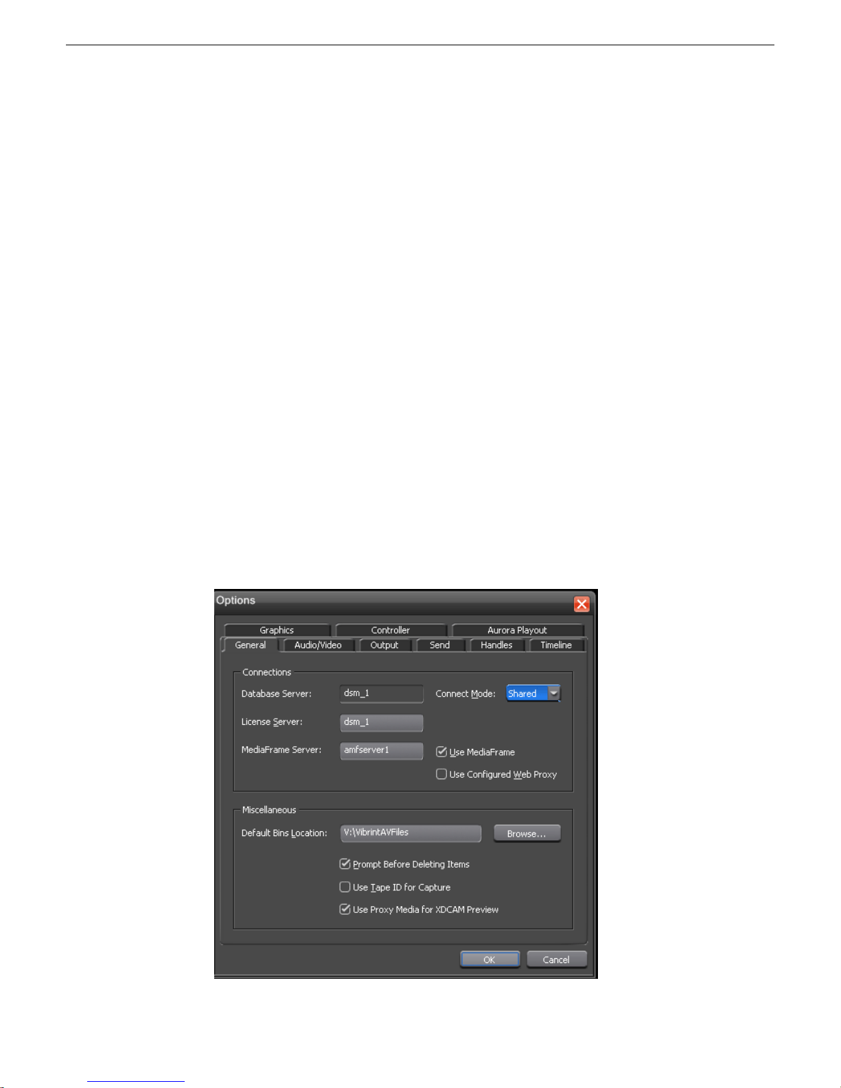
Option Configurations
In the Tools main menu, use the Options pulldown to configure Aurora Edit options
for your optional and external hardware and workflow:
The tabs included under the Options pulldown are summarized below:
• General tab: Set server connections and miscellaneous settings.
• Audio/Video tab: Set video standard, format, NTSC timecode, compression type,
bit rate, chroma format, and audio format.
• Output tab: When the Breakout Box (BOB) option is present, define analog audio
connectors and aspect ratio of SDI BNC out.
• Send tab: Set Send locations for completed sequences.
• Handles tab: Set handle durations for various file functions.
• Timeline tab: Set timeline choices for input/output channels, digital reference level,
default mix routing and other timeline functions.
• Graphics tab: Enable or disable the Orad graphics functionality.
• Controller tab: Set COM port for external controllers (if used).
• Aurora Playout tab: Set Primary/Backup and XMOS servers for Aurora Playout.
Aurora Edit Application Configuration
Options—General (Aurora Edit)
The first Options tab for Aurora Edit provides general Connections and Miscellaneous
settings. The various items to be configured are shown in the screen illustration and
described in the table below.
4 October 2010 Aurora Edit Installation Guide 93
Page 94

Aurora Edit Application Configuration
DescriptionOptionsSetting
Database Server
Connect Mode
Local
Shared
License Server
Use Media Frame
Use Configured Web Proxy
Displays the name of the database server when the
application is set up in shared mode.
In the Connect Mode pulldown, select Local if you are
using local disk storage and a local Aurora Edit database.
You have access to files on your local machine only.
Select Shared if you are using shared disk storage and
a shared database. You share the Bin with all Aurora Edit
workstations that are part of the network, according to
security settings.
Enter the name of the server where the Aurora Sys and
Aurora-GFX SabreTooth license resides.
Enter the name of the MediaFrame Server.MediaFrame Server
Select this checkbox to enable MediaFrame (you can
uncheck it to disable MediaFrame without losing the
server name.
NOTE: Aurora Edit LD must be connected in Shared
mode and use a MediaFrame server.
This checkbox will become active when MediaFrame is
turned on in the step above. When this checkbox is
selected, the application will continue to go through the
configured Web Proxy settings in order to communicate
with MediaFrame services. When unselected, web calls
through MediaFrame services will bypass the configured
settings.
Default Bin Location
Prompt Before Deleting Items
Use Tape ID for Capture
Use Proxy Media for XDCAM
Preview
Enter the default path to your media files. You may use
the Browse button to locate the server.
NOTE: V:\VibrintAVFiles is the default location.
Select this checkbox to receive a confirmation prompt
before deleting files. The setting is on by default.
Select this checkbox to identify which source tape a
particular clip came from; used in the Source Tool. This
setting is off by default.
Select this checkbox to view the low-resolution proxy
for media when previewing XDCAM files; doesn’ t affect
HD media, which always uses proxy media for
previewing. This setting is on by default.
94 Aurora Edit Installation Guide 4 October 2010
Page 95
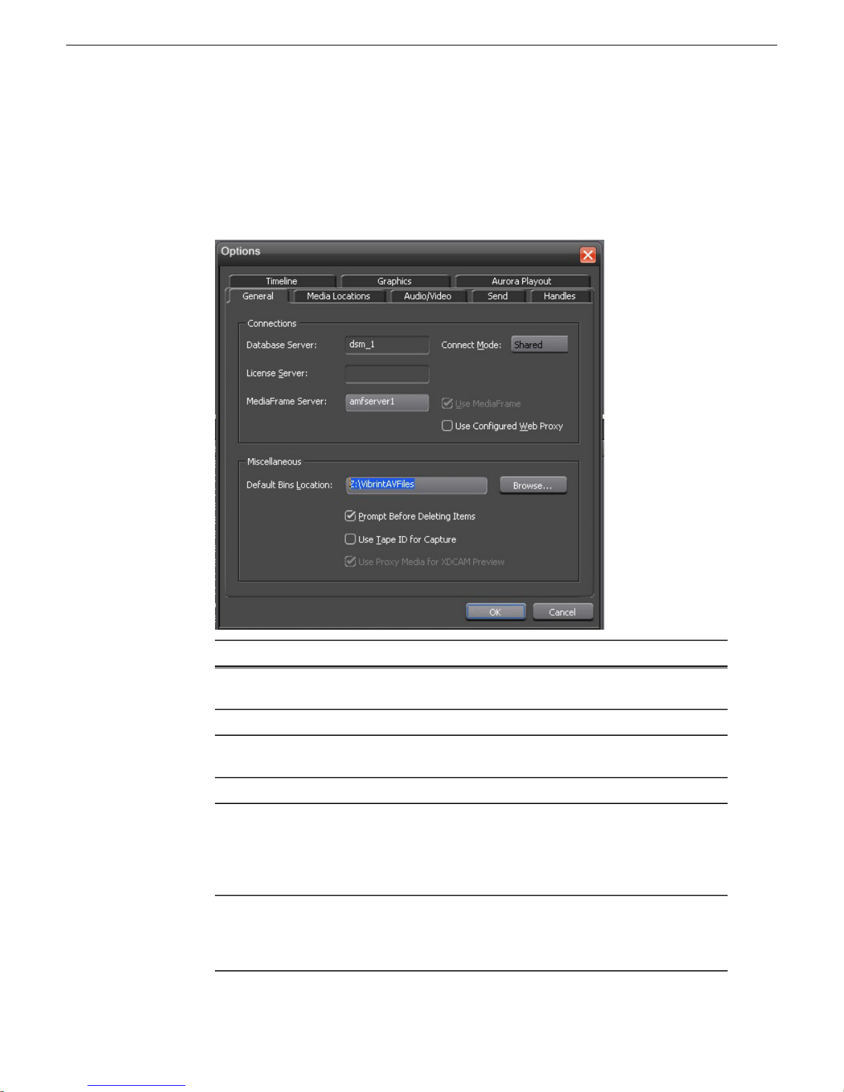
Options—General (Aurora Edit LD)
The first Options tab for Aurora Edit LD provides general Connections and
Miscellaneous settings. The various items to be configured are shown in the screen
illustration and described in the table below.
Aurora Edit Application Configuration
DescriptionSetting
Database Server
License Server
Use Media Frame
Use Configured Web Proxy
4 October 2010 Aurora Edit Installation Guide 95
Displays the name of the database server when the application
is set up in shared mode.
Aurora Edit LD is always in the Shared mode.Connect Mode
Enter the name of the server where the Aurora Sys and
Aurora-GFX SabreTooth license resides.
Enter the name of the MediaFrame Server.MediaFrame Server
Select this checkbox to enable MediaFrame (you can uncheck
it to disable MediaFrame without losing the server name.
NOTE: Aurora Edit LD must be connected in Shared mode
and use a MediaFrame server.
This checkbox will become active when MediaFrame is turned
on in the step above. When this checkbox is selected, the
application will continue to go through the configured Web
Proxy settings in order to communicate with MediaFrame
Page 96
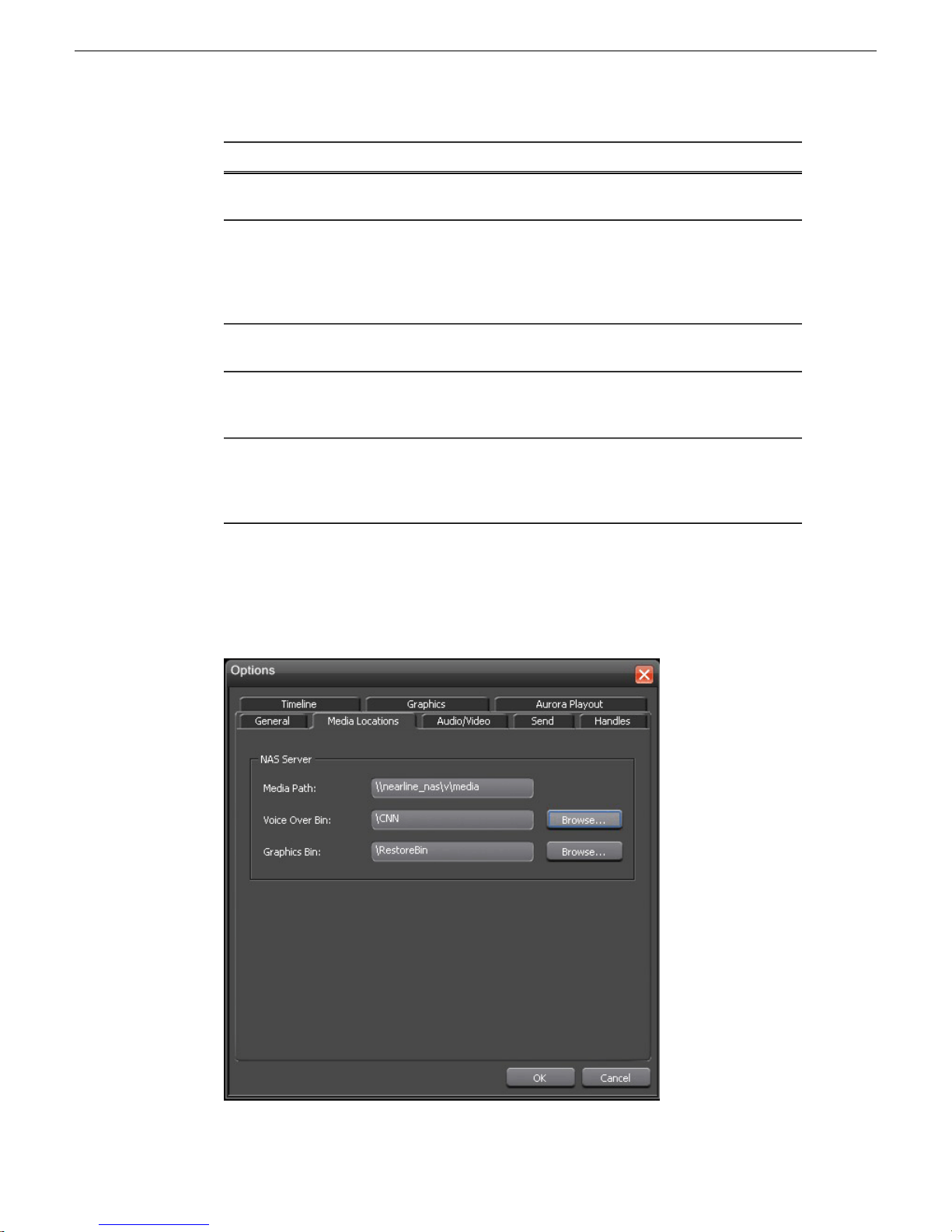
Aurora Edit Application Configuration
DescriptionSetting
services. When unselected, web calls through MediaFrame
services will bypass the configured settings.
Default Bin Location
Prompt Before Deleting
Items
Use Tape ID for Capture
Use Proxy Media for
XDCAM Preview
Enter the default path to your low resolution media files. You
may use the Browse button to locate the server. Do not use
the same directory as Aurora Edit ( V:\VibrintAVFiles is this
is default high resolution location for Aurora Edit). The Z:\
drive is used in this example.
Select this checkbox to receive a confirmation prompt before
deleting files. The setting is on by default.
Select this checkbox to identify which source tape a particular
clip came from; used in the Source Tool. This setting is off
by default.
Select this checkbox to view the low-resolution proxy for
media when previewing XDCAM files; doesn’t affect HD
media, which always uses proxy media for previewing. This
setting is on by default.
Options—Media Locations (Aurora Edit LD)
Use this tab to set the media locations required for the NAS server for Aurora Edit
LD.
96 Aurora Edit Installation Guide 4 October 2010
Page 97
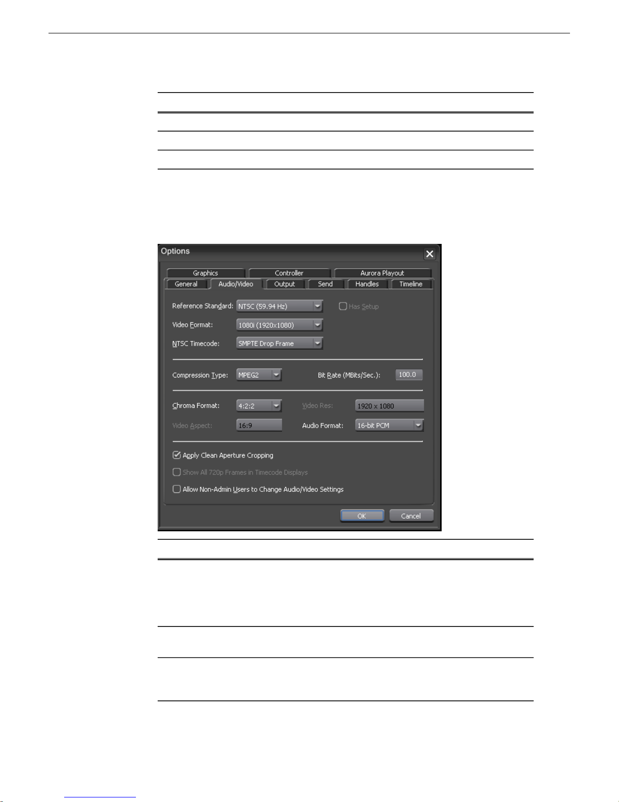
DescriptionSetting
Enter the path to the NAS serverMedia Path
Enter the directory on the NAS server for the Voice Over bin.Voice Over Bin
Enter the directory on the NAS server for the Graphics bin.Graphics Bin
Options—Audio/Video Settings
Use this tab to set overall audio and video configuration for the system.
Aurora Edit Application Configuration
Reference
Standard
Has Setup
Video
Format
4 October 2010 Aurora Edit Installation Guide 97
DescriptionOptionsSetting
NTSC
(59.94 Hz)
(50.00 Hz) 25 frames/second and is used in Europe, most of Asia, and
480i (SD)
or 576i
Select the Reference Standard you are using NTSC (default
setting) has a frame rate of 29.97 frames/second and is used
primarily in the Americas and Japan. PAL has a frame rate ofor PAL
Australia.
Select the Has Setup check box if the analog composite signal
carries setup information.
Select 480i Video Format for an interlaced (i) standard
definition (SD) television format (default setting) for NTSC;
select 576i for PAL. Select 720p for a progressive (p), high(SD) then
Page 98

Aurora Edit Application Configuration
DescriptionOptionsSetting
NTSC
Timecode
Type
720p
(1280x720)
or 1080i
(1920x1080)
SMPTE Drop
Frame
Non-drop
Frame
IMX30
IMX40
IMX50
DV25
DV50
DV100
AVCI-50
definition (HD) television format. Select 1080i for an
interlaced, high definition television format.
Recommended setting to avoid the time slipping problems
associated with non-drop frame; default setting.
Standard format used to represent timecode.SMPTE -
MPEG2 is the default compression type available in all formats.MPEG2Compression
Available in NTSC 480i (SD) and PAL 576i (SD) video
formats.
Bit Rate
MBits/Sec
Format
Aspect
Resolution
AVCI-100
4-50
MBits/Sec
4:1:1Chroma
4:2:0
4:2:2
4:3Video
16:9
720 x 480
720 x 576
Enter the Bit Rate specified by your system administrator. 50
mbits is the default setting. More than 25 mbits is optional.
The 4:1:1 Chroma Format is selected if you use DV25
compression.
Select the 4:2:0 or 4:2:2 Chroma Format if you use MPEG2
compression.
Select the 4:2:2 Chroma Format if you use DV50 or MPEG2
compression—4:2:2 offers more color resolution than 4:2:0
with MPEG2; this is the default setting.
Select 4:3 Video Aspect for a standard definition (SD)
television format; default setting.
Select 16:9 Video Aspect for a high definition (HD) television
format.
Select for NTSC systems using MPEG2 compression.720 x 512Video
Select for NTSC systems using DV25, DV50, or MPEG2
compression; default setting.
Select for PAL systems using DV25, DV50, or MPEG2
compression.
98 Aurora Edit Installation Guide 4 October 2010
Page 99

Aurora Edit Application Configuration
DescriptionOptionsSetting
Select for PAL systems using MPEG2 compression.720 x 608
Audio
Format
Apply Clean Aperture
Cropping
Show All 720p Frames in
Timecode Displays
Allow Non-Admin Users
to Change Audio/Video
Settings
Options—Output
The tab includes configuration for optional analog video connections from the optional
Breakout Box (BOB) and system aspect ratio setting.
16-Bit
PCM
24-Bit
PCM
The Aurora Edit application bit depth may be set for 16- or
24-bit . Both 16- and 24-bit audio can be mixed and matched
in the same Timeline. Records will take on the bit depth of the
configured setting, but media imports will preserve the current
depth of the source media. Sending will flatten audio to the bit
depth of the sequence.
By default, Aurora Edit automatically trims a small amount of
video around the edges of a frame to ensure a clean image.
This setting is on by default. Leave this option selected for SD
video; setting is optional for HD video.
When using the 720p video format, select this checkbox to
display all timecode in Aurora Edit as 60/50 frames per second.
When unselected, timecode displays in the standard 30/25
frames per second format. This setting is off by default.
Select this checkbox to allow all users to change audio or video
settings. This option is off by default.
4 October 2010 Aurora Edit Installation Guide 99
Page 100
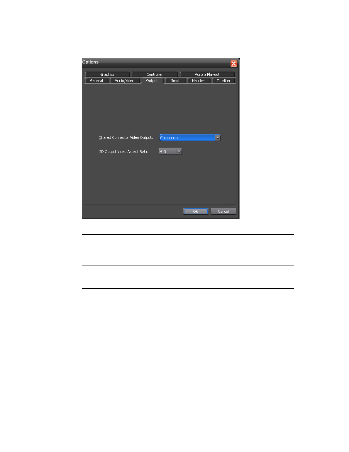
Aurora Edit Application Configuration
Shared Connector
Video Output
SD Output Video
Aspect Ratio
Options—Send
After completing a sequence you can send it to a playout machine or to a network
video server. To send completed sequences or individual clips, you first need to
configure Aurora Edit with each of your send locations.
A send location can be another Aurora Edit workstation, a Media Server, or a Bin you
specify. If you want to store completed sequences on your computer, you can also add
a send location for your PC.
Component
Composite and
Y/C
4:3
16:9
DescriptionOptionsSetting
Select the Video Connection option that
corresponds to the video source’s connection to
Aurora Edit through the optional Breakout box
(BOB). Component is the default setting.
Select the video aspect ratio for output. 4:3 is the
default aspect ratio.
100 Aurora Edit Installation Guide 4 October 2010
 Loading...