

Page 1
Aurora Browse
MEDIA ASSET MANAGEMENT PLATFORM
Installation and Configuration Guide
SOFTWARE VERSION 6.0b
071-8518-00
SEPTEMBER 2006
Page 2

Copyright Copyright © 2006 Grass Valley, Inc. All rights reserved. Printed in the United States of America.
Portions of software © 2000 – 2006, Microsoft Corporation. All rights reserved.
This document may not be copied in whole or in part, or otherwise r eproduced except as
specifically permitted under U.S. copyright law, without the prior written consent of Grass
Valley, Inc., P.O. Box 59900, Nevada City, California 95959-7900
This product may be covered by one or more U.S. and foreign patents.
Trademarks Grass Valley, K2, Aurora, Turbo, M-Series, Profile, Profile XP, NewsBrowse, NewsEdit,
NewsQ, NewsShare, NewsQ Pro, Aurora, and Media Manager are either registered
trademarks or trademarks of Grass Valley, Inc. in the United States and/or other countries.
Other trademarks used in this document are either registered trademarks or trademarks of the
manufacturers or vendors of the associated products. Grass Valley, Inc. products are covered
by U.S. and foreign patents, issued and pending. Additional information regarding Grass
Valley, Inc. trademarks and other proprietary rights may be found at
www.thomsongrassvalley.com.
Disclaimer Product options and specifications subject to change without notice. The information in this
manual is furnished for informational use only, is subject to change without notice, and should
not be construed as a commitment by Grass Valley, Inc. Grass Valley, Inc. assumes no
responsibility or liability for any errors or inacc uracies that may appear in this publication.
U.S. Government
Restricted Rights
Legend
Use, duplication, or disclosure by the United States Government is subject to restrictions as set
forth in subparagraph (c)(1)(ii) of the Rights in Technical Data and Computer Software clause
at DFARS 252.277-7013 or in subparagraph c(1) and (2) of the Commercial Computer
Software Restricted Rights clause at FAR 52.227-19, as applicable. Manufacturer is Grass
Valley, Inc., P.O. Box 59900, Nevada City, California 95959-7900 U.S.A.
Revision Status
Rev Date Description
January 31, 2003 Release to part number 071-8217-00
July 21, 2003 Release for software version 1.5 to part number 071-8217-01
May 25, 2004 Release for software version 2.0. Part number 071-8307-00.
December 16,
2004
August 2, 2005 Release for software version 3.0. New content for NewsShare NAS.
April 27, 2006 Release for software version 3.1. Part number 071-8424-01.
September 22,
2006
Release for software version 2.7. Added information about
Advanced Encoder, FlashNet archive, and DIVArchive. Part number
071-8307-01.
Part number 071-8424-00.
Release for Aurora software version 6.0
071-8518-00.
b. Part number
2 Aurora Browse Installation and Configuration Guide September 22, 2006
Page 3

Contents
Preface..................................................................................................................7
Chapter 1 System Overvi ew
Functional description .............................................................................................11
System diagram - K2 storage......................................................... .........................12
Design considerations - Aurora Browse with Aurora Edit...................................12
Legacy systems.......................................................................................................13
Chapter 2 Inst all ing Aurora Browse
Rack-mount hardware compone nts......................................... ...............................16
About cabling hardware compone nts....................................... ...... .........................16
Cable hardware: MediaFrame support....................................................................17
MediaFrame server instructions: XRE-2 platform...............................................17
MediaFrame server instructions: HAFT-2 platform.............................................18
MDI Server instructions......................................................................................20
Cable hardware: Proxy support...............................................................................21
Advanced Encoder instructions..........................................................................22
SmartBin Encoder instructions...........................................................................23
NAS instructions - Fastora..................................................................................24
About Aurora Browse software...................................... ...... ....................................24
Install software for K2 support.................................................................................27
Install the StorNext File System .........................................................................27
Installing the Generic iSCSI Client Software......................................................28
Other software installation considerations...............................................................30
Chapter 3 Configuring the system
Configuration overview - K2 storage.......................................................................32
Establish conventions........................ .................................. ..... ...... ..... ....................33
Machine naming convention...............................................................................33
MDI and Encoder logical names convention......................................................33
Ports and services mapping...............................................................................36
Configure network - K2 Storage..............................................................................37
Set up IP addresses and name resolution..........................................................37
Configure network settings on Production network machines............................37
Configure HAFT platform....................................................................................38
Configure network settings on Client network machines....................................38
Firewall considerations.......................................................................................39
Prepare for core configuration stages.....................................................................40
Prepare DSM ......................................................................................................40
Prepare SmartBins.............................................................................................40
Prepare Advanced encoders..............................................................................40
Add encoders to the K2 Storage System ...........................................................40
Configuring encoders with the K2 System Confi gu r ati on appl ic ati on............ 41
Calculating encoder bandwidth......................................................................45
Prepare NAS - Windows Fastora .......................................................................45
Verify NAS access..............................................................................................48
About the nbadmin account................................................. ...............................49
Accessing services.............................................................................................50
Accessing system configuration pages ..............................................................50
Stop services...........................................................................................................52
MediaFrame stage ..................................................................................................53
Configure Media Frame ASK: Register components..........................................54
Prepare MDI server............................................................................................56
Configure ASK Location: MDI server..................................................................57
Configure Proxy MDI..........................................................................................58
September 22, 2006 Aurora Browse Installation and Configuration Guide 3
Page 4

Contents
Configure K2 MDIs............................................................................................. 59
Configure Profile MDIs.......................................................................................60
Configure News MDIs ........................................................................................61
Configure M-Series MDIs................................................................................... 62
Test: MediaFrame stage ....................................................................................63
Checklist: MediaFrame stage............................................................................. 63
SmartBin encoder stage..........................................................................................64
Configure ASK Location: SmartBin encoder...................................................... 65
Configure Media Frame Core ASK: SmartBin encoder...................................... 65
Configure SmartBin Encoder Control.................................................................65
Configure Proxy Asset (NAS): SmartBin encoder.............................................. 66
Configure MPEG encoder: SmartBin encoder ...................................................66
Test: SmartBin encoder...................................................................................... 66
Checklist: SmartBin stage..................................................................................67
Advanced encoder stand-alone stage..................................................................... 68
Configure ASK Location: Advanced encoder.....................................................69
Configure Advanced Encoding Control..............................................................70
Configuring Encoder Mode............................................................................ 70
Configure Proxy Asset (NAS): Advanced encoder.............................................72
Configure MPEG encoder: Advanced encoder..................................................72
Test: Advanced encoder stand-alone stage - high-res source........................... 72
Test: Advanced encoder stand-alone stage - MPEG proxy source................... 74
Checklist: Advanced encoder stand-alone stage...............................................76
Advanced encoder + Server stage..........................................................................77
Configure Media Frame Core ASK: Advanced encoder.....................................77
Configure Rules Automation: Advanced encoder.............................................. 78
About configuring rules..................................................................................79
Tips for configuring rules........................................................... ..... ...... ...... ...79
Configure Asset Manager................................................................................... 80
About expired assets........................................................... ..... ...... ..... ...... ...... ...80
Test: Advanced encoder + Server stage - high-res source................................80
Checklist: Advanced encoder + Server stage.................................................... 81
EDL Export, Save, Conform stage.......................................................................... 82
Configure Profile MDI: Conform to air settings...................................................83
Configure NTFS MDI..........................................................................................84
Configure Media Frame Core ASK: NTFS......................................................... 84
Configure Conform Services.............................................................................. 85
Configure Export Services..................................................................................86
Configure Save EDL settings .............................................................................87
Test: EDL stage..................................................................................................88
Checklist: EDL stage.......................................................................................... 88
Archive stage .................. ...... ...... ..... ...... ...... ..... ....................................... ............... 89
Add archive MDI................................................................................................. 90
Verify archive preparations.................................................................................91
Avalon archive preparations..........................................................................91
FlashNet preparations...................................................................................91
DIVA preparations................................... ...... ..... ...... ...... ..... ..........................92
Network connectivity - all archive types.........................................................93
Configure ASK Location: Archive MDI host........................................................ 95
Configure Media Frame Core ASK: Archive....................................................... 95
Configure Avalon Archive MDI...........................................................................96
Configure FlashNet MDI.....................................................................................97
Configure DIVA MDI...........................................................................................98
Configure Archive Services................................................................................99
Test: Archive stage.............................................................................................99
Checklist: Archive stage.....................................................................................100
Deploy remaining machines for full system............................................................. 101
4 Aurora Browse Installation and Configuration Guide September 22, 2006
Page 5

Test system level interactions.................................................................................101
Multiple scavenge test........................................................................................101
Purge test........................................... ..... ...... ..... ........................................ ..... ...101
Add Aurora Browse Clients.....................................................................................102
Connect server and NAS to customer LAN........................................................102
Set up client PCs................................................................................................103
Configure Aurora Browse Licenses....................................................................104
Administering Aurora Browse user access..............................................................105
Configure Aurora Browse Groups......................................................................105
Configure Aurora Browse Users.........................................................................106
Managing Aurora Browse User sessions ...........................................................108
Adding custom fields...............................................................................................109
Testing Aurora Browse client operations.................................................................110
Chapter 4 Rec ov ery Plann in g
Encoder failure considerations................................................................................111
Server failure considerations...................................................................................111
Database maintenance and administration.............................................................111
Repairing a database that is unusable due to transaction log size ....................112
How to determine the size of the transaction log................................................112
Manually controlling transaction log growth........................................................113
Back up the transaction log ...........................................................................113
Shrink the transaction log ..............................................................................113
Setting up a database maintenance plan...........................................................113
Database Restoration.........................................................................................115
Chapter 5 Troubleshooting the system
Troubleshooting tools..............................................................................................117
MediaFrame troubleshooting tools.....................................................................117
Proxy troubleshooting tools................................................................................117
Proxy troubleshooting tips.......................................................................................118
Aurora Browse application troubleshooting tips......................................................120
Appendix A Component Interaction Diagrams
External Ingest Application............................................ ...... ..... ...............................121
SmartBin Ingest.......................................................................................................122
Metadata .................................................................................................................123
Scavenge ................................................................................................................124
EDL Export as Text File ..........................................................................................125
EDL Export to Aurora Edit database.......................................................................126
EDL Browse save ....................................................................................................127
EDL Conform on Profile ..........................................................................................128
EDL Conform via Aurora Edit..................................................................................129
Archive operations on Profile XP.............................................................................130
Archive operations on Aurora system .....................................................................131
Purge.......................................................................................................................132
Consolidate .............................................................................................................133
Appendix B Legacy systems
Three tier system diagram.......................................................................................135
Two tier system diagram version 2.0.......................................................................136
System diagram - Profile XP or Open SAN storage................................................137
Configuration overview - Profile XP/Open SAN ......................................................138
MediaFrame server instructions: Axiom platform....................................................139
Sequential encoder instructions..............................................................................140
Image Support Server (ISS) instructions.................................................................141
Single-channel encoder instructions .......................................................................142
September 22, 2006 Aurora Browse Installation and Configuration Guide 5
Page 6

Contents
RS-422 Cable Pinouts................................................................................... 143
NAS instructions - Serial ATA network platform................................................. 144
Live monitor encoder instructions....................................................................... 145
Router Gateway instructions........................................ .................................. ...... ...146
Prepare Profile Media Servers................................................................................146
NetTime system......................................................................................................148
Prepare NetTime..................................................................................................... 148
Prepare NetTime servers...................................................................................149
Prepare NetTime clients..................................................................................... 149
Prepare NAS - Serial ATA network platform...........................................................150
Prepare NAS - Linux Fastora.................................................................................. 153
Host table files......................................................................................................... 153
Encoder stand-alone stage..................................................................................... 156
Configure ASK Location: Single-channel encoder............................................. 157
Configure Ingest Control: Single-channel encoder.............................................157
Configure Proxy Asset (NAS): Single-channel encoder.....................................158
Configure media server: Single-channel encoder.............................................. 159
Configure MPEG encoder: Single-channel encoder..........................................160
Test: Encoder stand-alone stage ....................................................................... 160
Checklist: Encoder stand-alone stage................................................................ 162
Encoder + Server stage.......................................................................................... 163
Configure ASK Location: MediaFrame server.................................................... 164
Configure Media Frame Core ASK: Single-channel encoder............................. 164
Configure Ingest Scheduler: MediaFrame server...............................................165
Set up Aurora Browse client for configuration stage tests..................................166
Test: Encoder + Server stage.............................................................................166
Checklist: Encoder + Server stage..................................................................... 167
Router Gateway stand-alone stage.........................................................................168
Add Router Gateway.......................................................................................... 168
Configure ASK Location: Router Gateway.........................................................169
Configure Router Gateway.................................................................................169
Test: Router Gateway stand-alone stage........................................................... 169
Checklist: Router Gateway stand alone stage ................................................... 170
Router Gateway + Server stage.................................................... ...... ..... ...... ...... ...171
Add Router Gateway to Ingest Scheduler.......................................................... 172
Test: Router Gateway + Server stage................................................................173
Checklist: Router Gateway + Server stage........................................................ 173
Configure Profile MDI: Conform to air settings...................................................174
Add live monitor encoders....................................................................................... 175
Proxy troubleshooting tools..................................................................................... 175
Browse controlled ingest 1...................................... ..... ...... .................................. ...176
Browse controlled ingest 2...................................... ..... ...... .................................. ...177
Browse Ingest: Proxy MPEG Creation.................................................................... 178
Index...................................................................................................................... 179
6 Aurora Browse Installation and Configuration Guide September 22, 2006
Page 7

Preface
This Aurora Browse In stallation a nd Configuration Guide is part of a full set of
support documentation, described as follows:
•
•
•
Aurora Browse Installation and Configuration Guide — Provides explanations and
procedures for installing and configuring the system at a customer site. Includes
recovery planning and troubleshooting sections. This document is available in
printed form as part of the pr oduct bundle when you rece ive your new syste m. It is
also available in electro nic form (PDF file) on the Aurora Browse Application
CD-ROM.
Aurora Online Help — On the Aurora Hel p menu there is onlin e documentat ion for
each of the Aurora applications.
Aurora manuals — Each of the Aurora products has its own documentation set.
Refer to product manuals as follows:
- Aurora Edit
- Aurora Browse
- Aurora Ingest
- Aurora Playout
- Aurora Transfer
September 22, 2006 Aurora Browse Installation and Configuration Guide 7
Page 8

Preface
Grass Valley Product Support
To get technical as sista nce, ch eck on the stat us of proble ms, or r eport new pro blems,
contact Grass Valley Product Support via e-mail, the Web, or by phone or fax.
Contact Grass Valley first regarding p roblems with third party software on Grass
Valley products, such as the Microsoft
Server™.
Web Technical Support
To access support infor mation on the Web, v isit the pr oduct support Web page on the
Grass Valley Web site. Yo u ca n do wn loa d s oft war e or f ind sol utions to problems by
searching our Frequently Asked Questions (FAQ) database.
World Wide Web: http://www.thomsongrassvalley.com/support/
Technical Support E-mail Address: gvgtechsupport@thomson.net.
Phone Support
Use the following information to contact product support by phone during business
hours. Afterhours phone support is available for warranty and contract customers.
®
Windows® operating system and SQL
United States (800) 547-8949 (Toll Free) France +33 (1) 34 20 77 77
Latin America (800) 547-8949 (Toll Fr ee) Germany +49 6155 870 606
Eastern Europe +49 6155 870 606 Greece +33 (1) 34 20 77 77
Southern Europe +33 (1) 34 20 77 77 Hong Kong +852 2531 3058
Middle East +33 (1) 34 20 77 77 Italy +39 06 8720351
Australia +61 1300 721 495 Netherlands +31 35 6238421
Belgium +32 2 3349031 Poland +49 6155 870 606
Brazil +55 11 5509 3440 Ru s si a +49 615 5 870 606
Canada (800) 547-8949 ( Toll Free) Singapore +656379 1390
China +86 106615 9450 Spain + 34 91 512 03 50
Denmark +45 45968800 Sweden +46 87680705
Dubai + 971 4 299 64 40 Swit zerland +41 (1) 487 80 02
Finland +35 9 68284600 UK +44 870 903 2022
Authorized Support Representative
A local authorized s upport repre sentative ma y be availabl e in your coun try. To locat e
the support represe ntative for yo ur country, visi t the product suppor t Web page on t he
Grass Valley Web site.
8 Aurora Browse Installation and Configuration Guide September 22, 2006
Page 9

September 22, 2006 Aurora Browse Installation and Configuration Guide 9
Page 10

Preface
10 Aurora Browse Installation and Configuration Guide September 22, 2006
Page 11

Chapter 1
System Overview
Aurora Browse is a media management and ed itin g system. Aurora Browse support s
the complete newsroom work flow — from inges t to editi ng to distribut ion to arch ive.
This chapter includes the following topics:
• “Functional description” on page 11
• “System diagram - K2 storage” on page 12
• “Legacy systems” on page 13
Functional description
Aurora Browse allows desktop browsing of low-resolution proxy copies of both SD
and HD high-resolution video material. Aurora Browse provides a rich metadata
search engine that allows you to search for clips using various criteria. You can also
use the Aurora Browse application to edit stories using the low-resolution proxy,
which is accessible from the journal ist’s desktop. Aurora Browse creates various
low-resolution proxy formats for high-resolution material. Proxy formats include
MPEG-1, video thumbnails, and storyboards. From the Aurora Browse application
you can also archive and restore high-resolution material. Archived assets are still
visible from the Aurora Browse application.
The system is compatibl e with t he K2 stor age ar chite cture . Ing est is contro lled by an
ingest applicatio n, such as Aurora Ingest, and in corporates the K2 system as the video
server. The SmartBin encoder transfers an incoming feed into two formats: a proxy
low-resolution (MPEG-1) format stored on the proxy NAS, and a high-resolution
format stored the K2 storage system. Aurora Browse also monitors the K2 storage to
create proxy for new high-resolution material. In this way Au rora Edit master clips,
subclips and sequences are represented in the system for editing and manipulation.
The EDL export feature creates a sequence directly in the Aurora Edit target bin.
For descriptions of the machines used as pl atforms fo r the sys tem, refer to Chapter 2,
Installing Aurora Browse on page 15.
For descriptions of software components, refer to Appendix A, Component
Interaction Diagrams on page 121.
September 22, 2006 Aurora Browse Installation and Configuration Guide 11
Page 12
Chapter 1 System Overview
MediaFrame
Server
Proxy
NAS
t
t
y
e
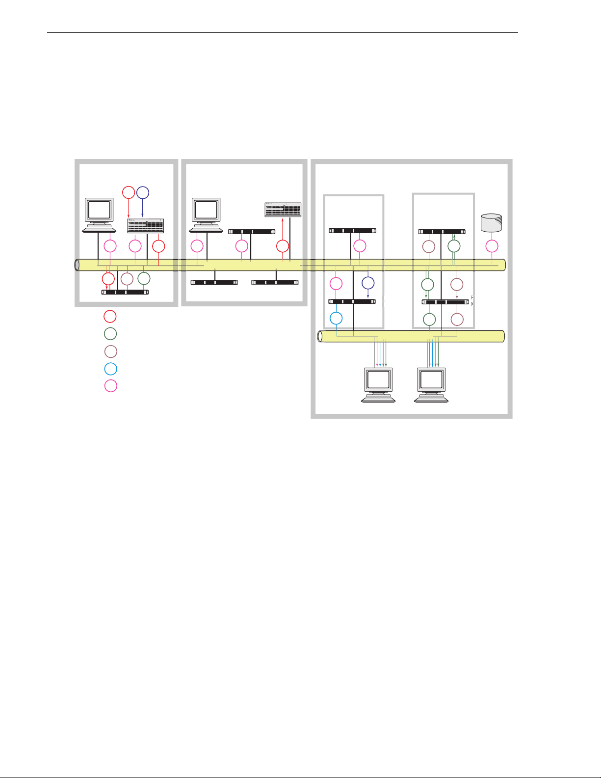
System diagram - K2 storage
This diagram illus trat es an ex ampl e archi tect ure fo r a s ystem t hat use s Auror a Inges t
for ingest and that accesses high-resolution media on K2 storage.
Aurora Ingest
AV
SmartBin Encoder****
AV
mpg
th/sb
web
info
Inges
AV
TC
Ingest
Media
Server*
!
info infoinfoinfo
AV
mpg
th/sb
High-res Audio/Video
MPEG1 low-res proxy video
Thumbnail, storyboard
Web application html pages
MediaFrame Core communications, such
as between MDIs, ASK, and Resolver.
Aurora Edit
Production Network*** (Gb)
Conform server
Edi
Media
Storage**
DSM
(News MDI server)
Aurora FTP server
(archive)
rowse
!
AV
iaFram
MDI Server
info
web
info
clk
Client Network
Aurora Browse Clients
The Ingest Media Server can be a K2 system or an M-Series system.
*
**
The Media Storage is a K2 system.
On large systems the Production Network can be separated into two
***
networks: one for media and one for control.
The SmartBin Encoder also bridges between the Edit and
****
the Browse Proxy systems.
th/sb
mpg
mpg
Prox
Advanced
Encoder
mpg
th/sb
th/sb
Archive
info
The system i llustrated here demonstrates the full range of hardware platform types.
Smaller systems might not include all types of hardware platforms. Consult the
system design for your specific system to determine th e hardware platfo rms you must
install.
Design considerations - Aurora Browse with Aurora Edit
Take the following into considerations when establishing the workflow for your use
of Aurora Browse:
Minimize proxy creation for short-lived material — The editing process generates
multiple pieces of transitional media, but there is no need to create proxy
representation s of this transitio nal media. To do so creates an unneces sary load on the
system and affects performance.
To avoid this , create at least three designated locations in which material re sides to
match your workflow, as follows:
• Inbox — This is the location in which newly acquired material arrives. Use a
12 Aurora Browse Installation and Configuration Guide September 22, 2006
Page 13

SmartBin—or configure Aurora Browse rules—to automatically create proxy for
this material, so you can use Aurora Browse to evaluate and select material for
further editing.
• Workspace — This is the location in which you store material undergoing the
editing process. Do not c onfigure any Aurora Browse rule s to c reate pr oxy for t his
material. This saves encoding resources.
• Outbox — This is th e location in wh ich you place materi al that has been e dited and
is usable in its current state. You might have one outbox for on-air material and one
outbox for review ma terial. Configure Aur ora Browse rules to cr eate proxy for thi s
material, so you can use Aurora Browse to select and use this material.
Legacy systems
This manual documents Browse systems using K2 systems for media storage.
Existing systems, such as those using Prof ile XP/Open SAN for media storage, do not
match the systems documented in this manual.
You can find information about earlier systems in Appendix B, Legacy systems on
page 135. If you need the entire overview and task flow for working on a legacy
system, you should refer to th e version of this manual th at corresponds to the sof tware
version around whic h your syste m was origin ally buil t. Refer to “Revision Sta tus” on
page 2 of this manual for information about previous manual versions.
Legacy systems
September 22, 2006 Aurora Browse Installation and Configuration Guide 13
Page 14

Chapter 1 System Overview
14 Aurora Browse Installation and Configuration Guide September 22, 2006
Page 15

Chapter 2
Installing Aurora Browse
This chapter provides in struc tions for ins talling the hardware plat forms and software
components that suppo rt the system. Use t he instructions that are appropr iate for your
system.
The instructions in this chapter are as follows:
• “Rack-mount hardware components” on page 16
• “About cabling hardware components” on page 16
• “Cable hardware: MediaFrame support” on page 17
• “Cable hardware: Proxy support” on page 21
• “About Aurora Browse software” on page 24
• “Other software installation considerations” on page 30
When you are done installing the hardware and software, continue with Chapter 3,
Configuring the system and Chapter 4, Recovery Planning to c omplete the instal lation
of your system.
September 22, 2006 Aurora Browse Installation and Configuration Guide 15
Page 16

Chapter 2 Installing Aurora Browse
Rack-mount hardware components
Follow the instructions you received with the rack-mount hardware to install each
component of the system. One rack-unit spacing is recommended between
components for ventilation.
About cabling hardware components
Refer to the system design for your particular system and the appropriate system
diagram in Chapter 1, System Overview to identify the ha rdware com ponents and
cabling for your s ystem. Then turn to the appro priate cabling i nstructions a nd connect
cables as required.
Be aware of the following as you cable your system:
• Zoning is not required on the Ethernet switch if five or less clients are active. If
more than five clients are using the system, it is strongly recommended that you
use an isolated switch or a shared, zoned switch to isolate the client-side LAN.
Network traffic from the internal LAN is minimized.
• You may want to postpone cabling to external networks until after configuring
respective IP addresses.
16 Aurora Browse Installation and Configuration Guide September 22, 2006
Page 17
Cable hardware: MediaFrame support
Cable hardware: MediaFrame support
The following sections provide instructions for hardware pieces that support
MediaFrame components. Use the instructions that apply to your system design.
• “MediaFrame server instructions: XRE-2 platform” on page 17
• “MediaFrame server instructions: HAFT-2 platform” on page 18
• “MDI Server instructions” on page 20
MediaFrame server instructions: XRE-2 platform
The central component of the system is the MediaFram e server. Depending on the
design of your system, it can host the following software components:
• The Aurora Br owse web-app lication for u ser interaction
• The Rules Wizard for background processing
• The database and Managed Device Interface services for holding and relating
assets in t he system.
The server connects to all encoders and the Network Attached Storage via the
network. Refer to the system diagrams in Chapter 1, System Overview. The client
network is available for access to the web application.
Power
For the MediaFrame server yo u have th e optio n of the XRE- 2 plat form , as expla ined
in this section, or the HAFT-2 platform, as explained in “MediaFrame server
instructions: HAFT-2 platform” on page 18.
Cable as illustrated.
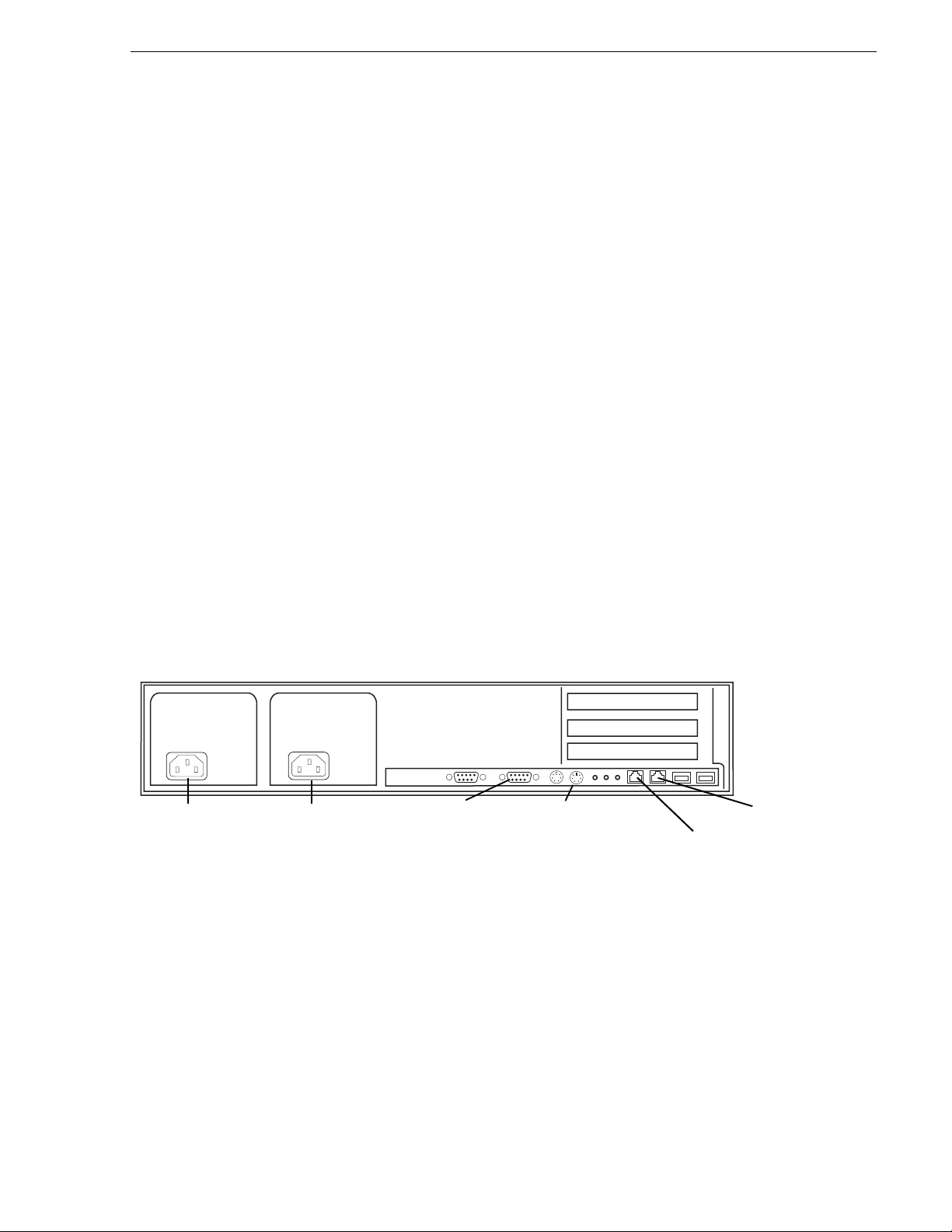
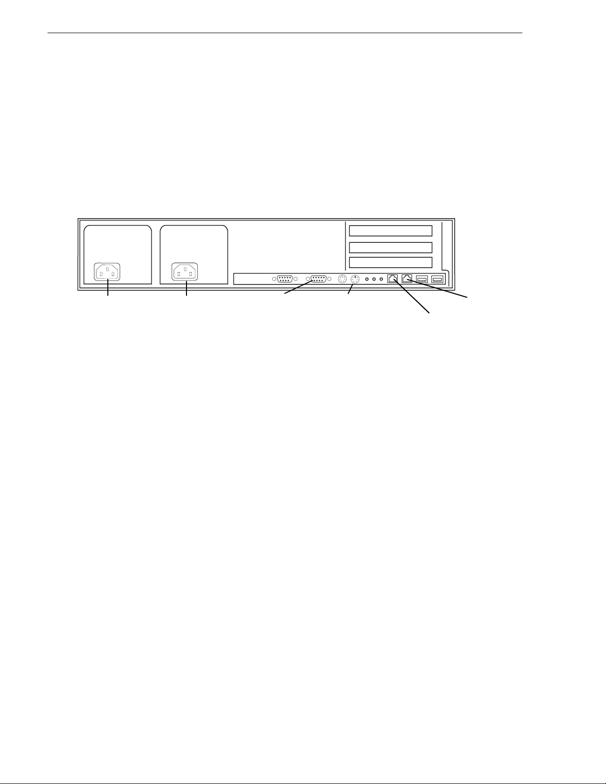
XRE-2 platform (Dell 2850)
Power
VGA cable
to KVM
Keyboard/mouse
port to pigtail
to KVM
LAN port 2
LAN port 1
Cable as illustrated and as follows:
• For systems wi th one unified Product ion Network, connec t port 1 to the Produc tion
Network.
• For systems with a Production Network consisting of a media network and a
control network, connect port one to the control network.
• Connect port 2 to the Client Network.
September 22, 2006 Aurora Browse Installation and Configuration Guide 17
Page 18
Chapter 2 Installing Aurora Browse
MediaFrame server instructions: HAFT-2 platform
For the MediaFrame server you have the option of the High Availability, Fault
Tolerant (HAFT) platform, also known as the Marathon platform. This platform is
made up of two interconnected servers.
NOTE: It is no longer recommended to install Windows Media Player on the HAFT
platform because of compatibil ity problems, so you can not run the Aurora Browse
application locally on the HAFT platform.
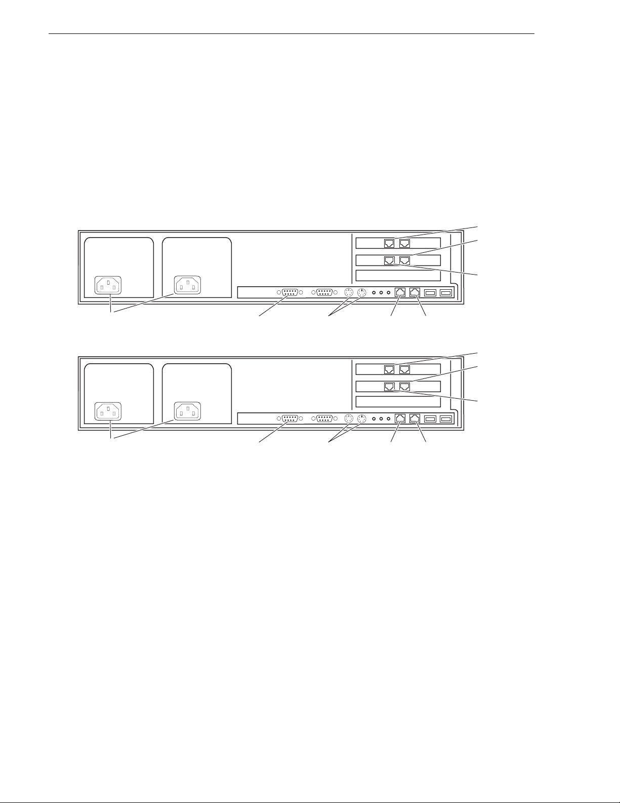
HAFT-2 platform (Dell 2850 servers)
PCI-3 A B
AB
PCI-2
LAN port 2
LAN port 1
CoServer
Management
port
Power
Power
VGA cable
to KVM
VGA cable
to KVM
Keyboard/mouse
ports to pigtail
to KVM
Keyboard/mouse
ports to pigtail
to KVM
CoServer
Link port 2
PCI-3 A B
AB
PCI-2
CoServer
Link port 2
CoServer
Link port 1
LAN port 2
LAN port 1
CoServer
Management
port
CoServer
Link port 1
Cable as illustrated and as follows:
• For systems with one unifi ed Production Network, connect port 1 and the CoServer
Management port to the Production Network.
• For systems with a Production Network consisting of a media network and a
control network, connect port one and the CoServer Management port to the
control network.
• Connect port 2 to the Client Network.
• Interconnect CoServer Link ports with cross-over cables.
• Connect power cables to a power supply.
Power supply units are hot-swappable.
18 Aurora Browse Installation and Configuration Guide September 22, 2006
Page 19

MediaFrame server instructions: HAFT-2 platform
To power up the HAFT platf orm, use t he norma l proc edures f or the se rver and log in
to the Windows operating system as normal. The virtual server runs in a full screen
window. To get to the physical server desktop, press
To power down the HAFT platform, right-click the system tray icon and select
Manage Endurance Configuration | Shutdown. This does an orderly shutdown of the
virtual server and the physical server.
Also refer to “Configure HAFT platform” on page 38 for network configuration
procedures.
Ctrl + Shift + F12.
September 22, 2006 Aurora Browse Installation and Configuration Guide 19
Page 20
Chapter 2 Installing Aurora Browse
MDI Server instructions
The MDI server is host for the Managed Device Interface (MDI) services, through
which the system gets i ts visibility of t he assets on the va rious machines in the s ystem.
The MDI server is an optiona l component. It runs on the XRE-2 pl atform. On systems
without a MDI server, the MDI services can run on the MediaFrame server or other
Aurora Browse machine.
Cable as illustrated.
XRE-2 platform (Dell 2850)
Power
Power
VGA cable
to KVM
Keyboard/mouse
port to pigtail
to KVM
LAN port 2
LAN port 1
Cable as illustrated and as follows:
• For systems with o ne unified Producti on Network, connect port 1 t o the Production
Network.
• For systems with a Production Network consisting of a media network and a
control network, connect port one to the control network.
• Connect port 2 to the Client Network.
20 Aurora Browse Installation and Configuration Guide September 22, 2006
Page 21

Cable hardware: Proxy support
The following sections provide instructions for hardware pieces that support the
processing and stor age of prox y media. Use the inst ructions that apply to y our syst em
design.
• “Advanced Encoder instructions” on page 22
• “SmartBin Encoder instructions” on page 23
• “NAS instructions - Fastora” on page 24
Cable hardware: Proxy support
September 22, 2006 Aurora Browse Installation and Configuration Guide 21
Page 22
Chapter 2 Installing Aurora Browse
Advanced Encoder instructions
The following components are hosted by the Advanced encoder:
• Thomson Proxy Transfer service.
• Aurora FTP service.
The Advanced Encoder does the following:
• Creates MPEG-1 proxy versions of high-reso lut ion video assets that al re ady exist
or are actively being recorded on a video server
• Processes MPEG-1 proxy content
• Extracts dynamic scene detection images for storyboard/thumbnail creation
The Advanced Encoder processes entirely in the digital domain. The SD Advanced
Encoder runs on the XRE-3 pl atform. The HD Advanc ed Encoder runs on the XRE-4
platform.
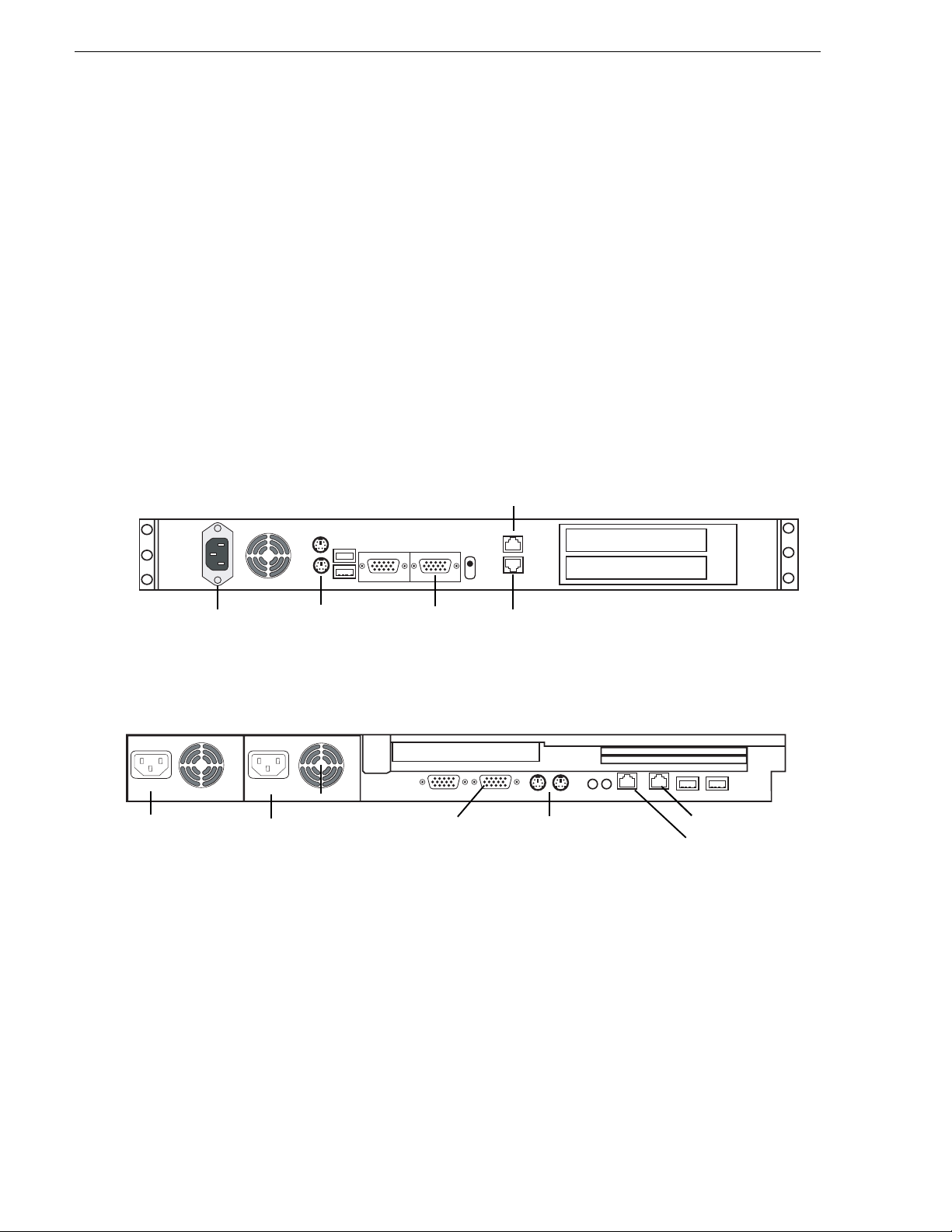
XRE-3 (Dell 850) platform
Gigabit port 1
Power
Power
XRE-4 (Dell 1850) platform
Keyboard/mouse
port to pigtail
to KVM
Power
VGA cable
to KVM
VGA cable
to KVM
Gigabit port 2
Keyboard/mouse
port to pigtail
to KVM
Gigabit port 1
Gigabit port 2
Cable as illustrated and as follows:
• For systems with one unified Production Network, connect Gigabit port 1 to the
Production network. Gigabit port 2 is unused.
• For systems with a Production Network consisting of a media network and a
control network, conn ect Gigabit por t 1 to the media n etwork and Gigabi t port 2 to
the control network.
22 Aurora Browse Installation and Configuration Guide September 22, 2006
Page 23
SmartBin Encoder instructions
The following components are hosted by the SmartBin encoder:
• Thomson SmartBin Proxy Transfer service. Refer to “About Aurora Browse
software” on page 24.
• SmartBins Service and Aurora FTP service. Refer to “Other software installation
considerations” on page 30.
The SmartBin encoder does the following:
• Creates MPEG-1 proxy versions of high-resolution material
• Processes high-resolution material
• Extracts dynamic scene detection images for storyboard/thumbnail creation
The SmartBin encoder processes entirely in the digital domain. The SmartBin
encoder runs on the XRE-3 platform . The HD SmartBin encoder runs on the XRE-4
platform.
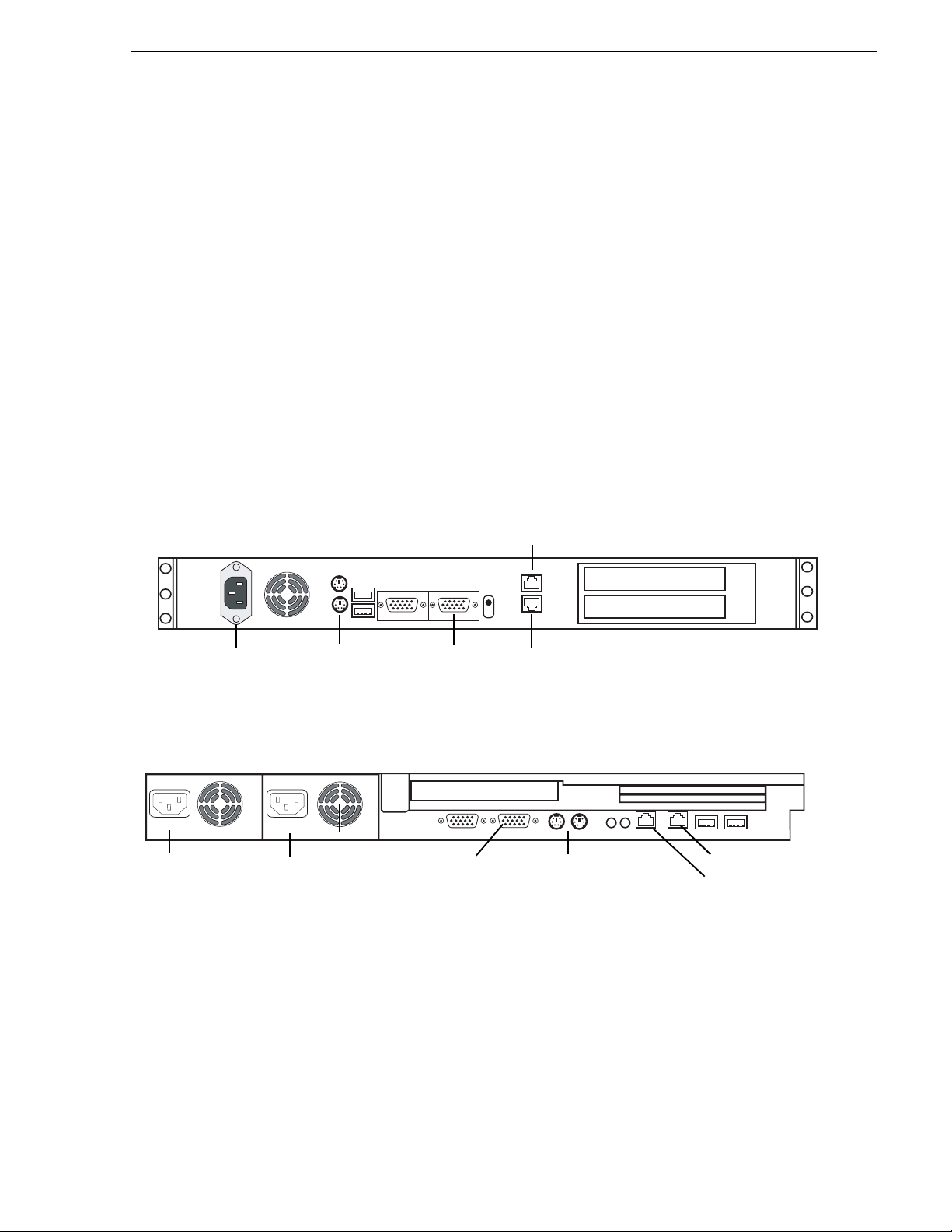
XRE-3 (Dell 850) platform
SmartBin Encoder instructions
Power
Gigabit port 1
Power
XRE-4 (Dell 1850) platform
Keyboard/mouse
port to pigtail
to KVM
Power
VGA cable
to KVM
VGA cable
to KVM
Gigabit port 2
Keyboard/mouse
port to pigtail
to KVM
Gigabit port 1
Gigabit port 2
Cable as illustrated and as follows:
• For systems with one unified Production network, connect Gigabit port 1 to the
Production network. Gigabit port 2 is unused.
• For systems wit h a Production netwo rk consisting of a me dia network and a co ntrol
network, connect Gigabit port 1 to the media network and Gigabit port 2 to the
control network.
September 22, 2006 Aurora Browse Installation and Configuration Guide 23
Page 24
Chapter 2 Installing Aurora Browse
NAS instructions - Fastora
The Network Attached Storage (NAS) unit provides storage for MPEG-1 proxy
video, storyboards, and thu mb nai ls . It may als o be con fi gur ed to stor e Edi t Dec is ion
Lists (EDL) that are saved to the system. Encoders are configured to write to specific
locations on the NAS via 100Tx connections over the network. Client access is
provided via Gigabit Ethernet uplink to the Client Network.
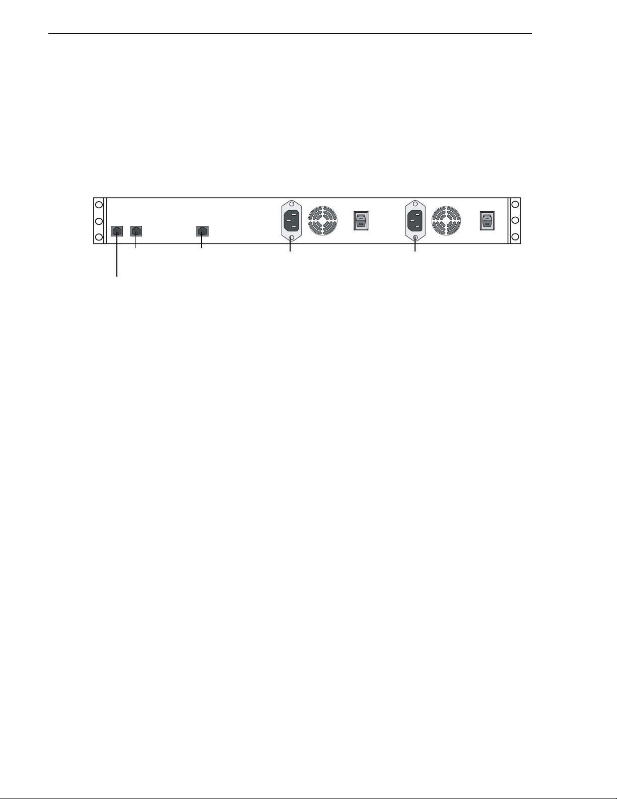
Aurora Browse Proxy NAS (Fastora 104)
LAN port 1 LAN port 2
Gigabit Ethernet
cable to LAN
or clients
Power
Cable as illustrated and as follows:
• For systems with one unified Production network, connect LAN port 1 to the
Production network.
• For systems wit h a Production net work consisting of a media network and a c ontrol
network, connect LAN port 1 to the media netwo rk and LAN por t 2 to the control
network.
• Connect Gigabit port 1 to the Client network.
• Connect both power cables from the back of the NAS to a power supply.
Power supply units are hot-swappable. Once power is applied using switches on the
rear panel, use t h e po we r swi tc h on the front pan el to power down. Failur e to use the
front switch will cause the disk array to rebuild on the next power up.
About Aurora Br owse software
In a new syste m, the hardware platforms come from the factory with software
pre-installed, so you should not need to install Aurora Browse software.
Power
If you need to install softwa re for an upgrade, refer to the instruction s listed below for
general information about Aurora Browse software. For version-specific instructions,
check Aurora Browse Release Notes. Also refer to “Other software installation
considerations” on page 30.
Remember to backup up the database before upgrading software, as explained in
Chapter 4, Recovery Planning.
The following installation programs are on the Aurora Browse Application CD:
• …\SingleChannelEncoder\Setup.exe — Use this setup file to install Aurora
Browse software on a single-channel encoder.
• …\AdvancedEncoder\Setup.exe — Use this setup file to install Aurora Browse
software on an Advanced encoder.
24 Aurora Browse Installation and Configuration Guide September 22, 2006
Page 25

About Aurora Browse software
• …\SmartBinEncoder\Setup.exe — Use this setup file to install Aurora Browse
software on a SmartBin encoder.
• …\Server\Setup.exe — Use this setup file to install Aurora Browse software on the
MediaFrame server as wel l as other Auror a Browse machines . The followin g table
indicates the machines on which the software components are typically installed.
You might install components differently, depending on the design of your
particular system.
Install Components MediaFrame
Core Services
Managed Devices:
FlashNet Archive
Profile
Proxy
NTFS
Avalon Network Archive
DIVArchive
News
M-Series
K2
Aurora Browse Application
Ingest
server
!
!
!
!
MDI Server Router Gateway DSM
!
!
!
!
!
!
!
!
Router Gateway
September 22, 2006 Aurora Browse Installation and Configuration Guide 25
!
Page 26
Chapter 2 Installing Aurora Browse
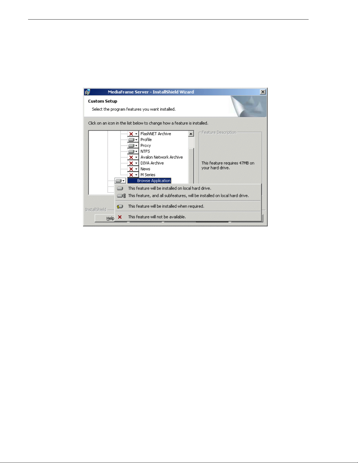
To install the software components listed in the preceding table, run the MediaFrame
server install program and when you arrive at the Custom Setup screen, do the
following:
If a component that you want to install displays a red X, click the component and
This feature will be installed on local hard drive.
select
If a component that you do not want to install does not display a red X, click the
component and select
This feature will not be available.
To upgrade Aurora Browse soft ware from a previous versi on, refer to Aurora Br owse
Release Notes for version-specific instructions.
NOTE: When upgrading software, read messages and respond carefully. Do not
accept the default “Yes” when prompted to delete databases.
26 Aurora Browse Installation and Configuration Guide September 22, 2006
Page 27
Install software for K2 support
If your system includes a K2 Storage System, on Advanced Encoders and SmartBin
encoders you need to insta ll the following software, in this order:
• StorNext File System
• Grass Valley Generic iSCS I Client Installation
After installing soft ware, configuration is also required, as inst ructed in the follo wing
sections later in this manu al:
• “Prepare SmartBins” on page 40
• “Prepare Advanced encoders” on page 40
• “Add encoders to the K2 Storage System” on page 40.
Install the StorNext File System
The StorNext File Sys tem software is locat ed on the Aur ora Suite CD-ROM. Refer to
release notes to verify the version.
NOTE: Use the standard SNFS installer, not the “simple” installer which is
designed for K2 systems only.
Install software for K2 support
To install the StorNext software:
1. Navigate to the directory that contains the software.
2. Double-click on the setup.exe file.
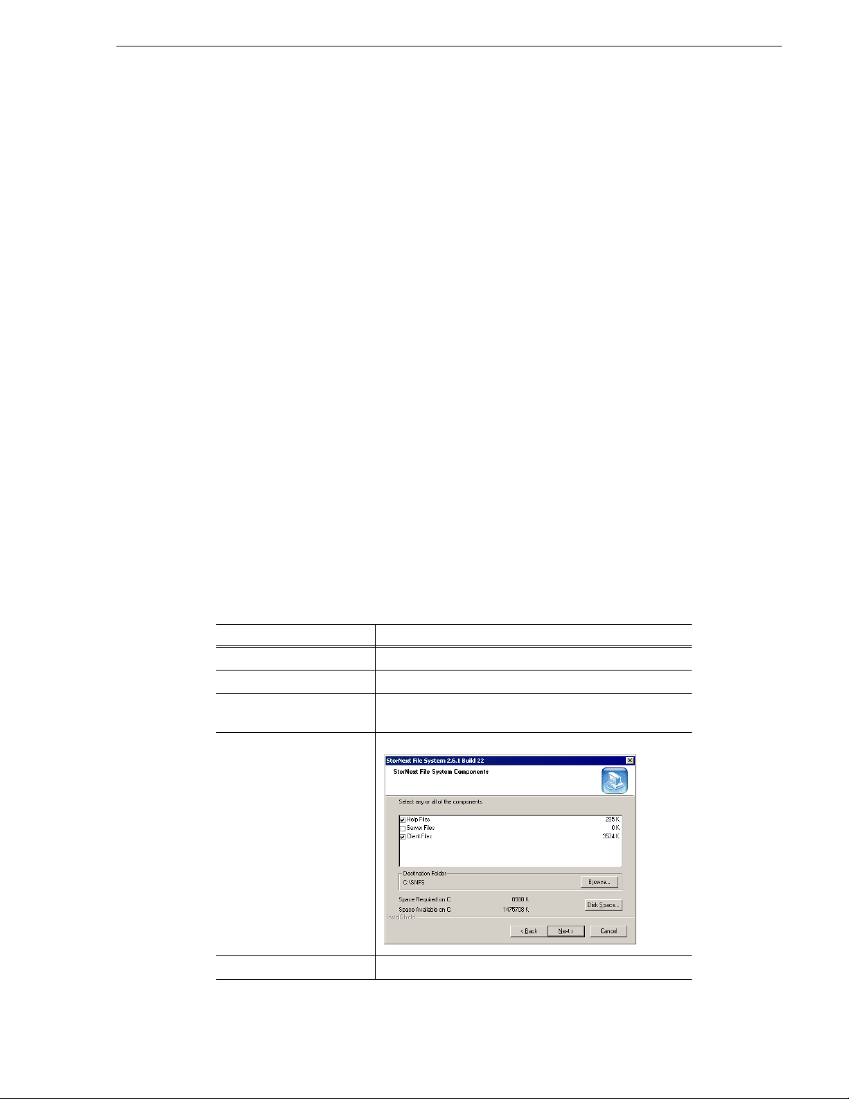
3. Install the software following these instr uct ions:
On this screen... Do this...
Welcome (2 screens) Click Next.
License Agreement Click Yes.
Choose Destination
Location
StorNext File System
Components
Accept the default location and click
Help Files and Client Fi les; do not select Se rver Files.
Select
Next.
Select Program Folder Accept the default location and click
September 22, 2006 Aurora Browse Installation and Configuration Guide 27
Next.
Page 28

Chapter 2 Installing Aurora Browse
On this screen... Do this...
Start Copying Files Click Next.
Choose Options to Complete
the Installation
Leave the checkbox blank and click Next.
File System Name Service
Locations
Confirm File System Name
Services Host List
Establish StorNext File
System Drive Mapping and
Credentials?
StorNext File System Setup Click
Enter the name or IP address of the K2 Media Server and
click
Next.
Click
Next.
No; this will be configured autom atically when you run
Click
the K2 Configuration applicati on later.
Finish.
4. Reboot the computer when prompted.
Installing the Generic iSCSI Client Software
The Generic iSCSI Client soft ware is located on t he Aurora Suite CD-ROM. Refe r to
release notes to verify the version.
To install the software:
1. Navigate to the directory that contains the software.
2. Double-click on the setup.exe file.
The Microsoft iSCSI Initia tor software also installs . When the Micr osoft iSCSI
Initiator software install completes, the Generic iSCSI Client software install
continues.
3. Once the Gene ric iSCSI software is installed, restart the machine.
4. When the machine comes back up, check the services as follows:
•Go to
Start | Settings | Control Panel | Administrative Tools | Services. The
28 Aurora Browse Installation and Configuration Guide September 22, 2006
Page 29
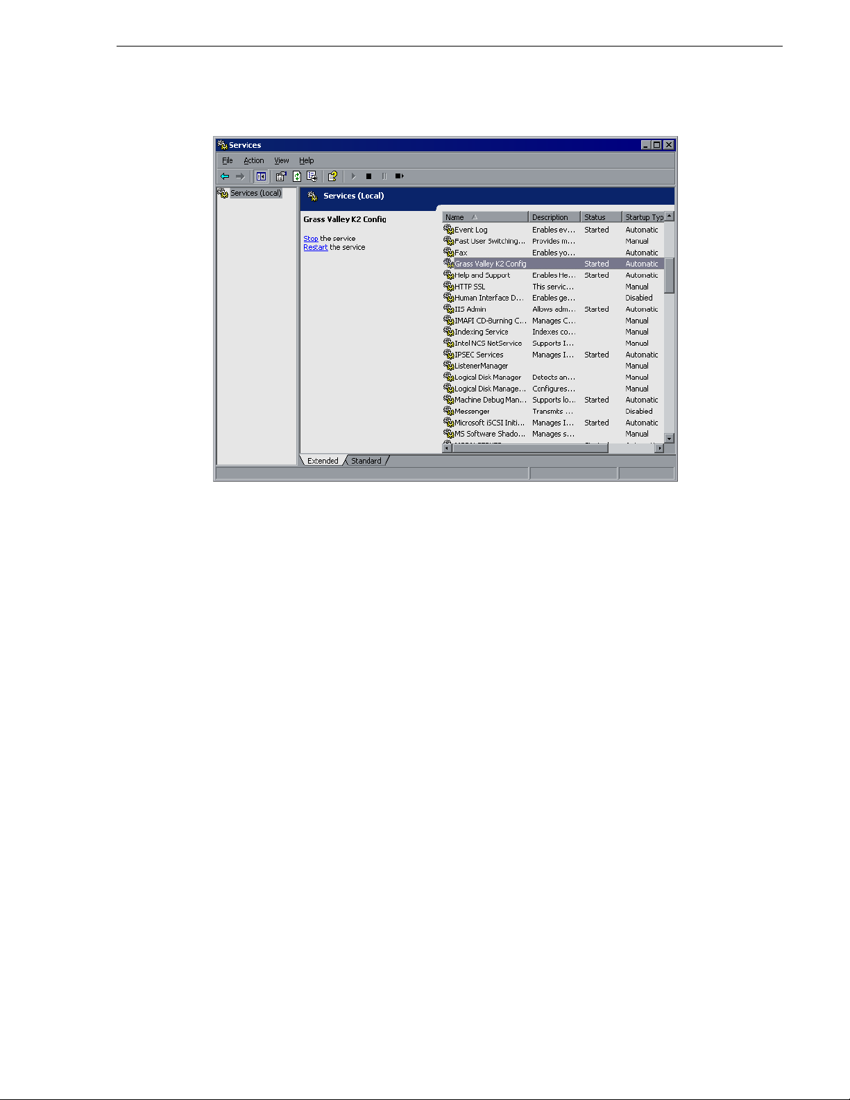
Services Control Panel opens
Installing the Generic iSCSI Client Software
• Make sure that the service named “Grass Valley K2 Config” is starte d.
September 22, 2006 Aurora Browse Installation and Configuration Guide 29
Page 30

Chapter 2 Installing Aurora Browse
Other software installation considerations
• Make sure that /Aurora FTP is installed on the Advanced Encoder.
• To support archive functionality, you must install a unique Aurora FTP on a
platform somewhere in the system. Refer to “Archive stage” on page 89.
• The standard Aurora Browse application is a web-based application. As such it is
installed on the MediaFrame serve r and served to ind ividual cl ient PCs via HTTP.
In contrast, the Advanced Edit application is a Windows executable and it is
installed locally on each client PC. There is no requirement to inst all the Advanced
Edit application on the MediaFrame server. You can find the installation file for
Advanced Edit on the Advanced Edit Installation CD.
30 Aurora Browse Installation and Configuration Guide September 22, 2006
Page 31

Chapter 3
Configuring the system
You can use the topics in this chapter in the following ways:
• Initial configuration — After your system components are rack mounted, cabled,
and the physical installation process is complete, continue with the configuration
instructions in this chapter to create a working system. You can follow the
path or the
“Configuration overview - K2 storage” on page 32.
• Customizing — After the system is functioning, you can go back to the
configuration pages and modify the settings documented in this manual as
Advanced ! to customize the system to fit any special workflow requirements.
The topics in this chapter include the following:
• “Configuration overview - K2 storage” on page 32
• “Establish conventions” on page 33
• “Configure network - K2 Storage” on page 37
• “Prepare for core configuration stages” on page 40
Advanced path through the core configuration stages, as explained
Basic
• “Stop servic es” on page 52
• “MediaFrame stage” on p age 53
• “SmartBin encoder stage” on page 64
• “Advanced encoder stand-alone stage” on page 68
• “Advanced encoder + Server stage” on page 77
• “EDL Export, Save, Conform stage” on page 82
• “Archive stage” on page 89
• “Deploy remaining machines for full system” on page 101
• “Test system level interactions” on page 101
• “Add Aurora Browse Clients” on page 102
• “Administering Aurora Browse user access” on page 105
• “Adding custom fiel ds” on page 109
• “Testing Aurora Browse client operations” on page 110
September 22, 2006 Aurora Browse Installation and Configuration Guide 31
Page 32

Chapter 3 Configuring the system
Configuration overview - K2 storage
Start
Establish
Conventions
- page 33 -
Configure
Network
- page 37 -
Prepare NAS,
etc
- page 40 -
MediaFrame
Stage
- page 53 -
SmartBin
Encoder
Stage
- page 64 -
Adv. Enc.
Stand-alone
Stage
- page 68 -
Adv. Enc. +
Server
Stage
- page 77 -
EDL
Stage
- page 82 -
Archive
Stage
- page 89 -
Administer
User
Access
-page 105-
End
Basic Path
-page 102-
Stop
Browse
Services
- page 52 -
Configure
Test
Configure
Test
Configure
Test
Configure
Test
Configure
Test
Configure
Test
Add
Browse
Clients
Advanced Path
Add
remaining
S.B. Enc.
Add
remaining
Adv. Enc.
System
Interaction
Test
-page 101-
page 101
page 101
This flowchart illustrates the major tasks required
for configuring a syste m that accesses K2 storage .
Before beginning th is task flow make sure that t he
Aurora Edit system is full y func tioni ng on t he K2
storage. You should have at least one SmartBin
Encoder as part of the Aurora Edit/K2 system. In
this role, the SmartBin Encoder is not yet being
used as an Aurora Browse machine. Rather, it is
just used to host the SmartBins service.
Core configuration tasks are broken down into
stages. You can work through the configuration
stages in different ways, as follows:
If you are new to the s ystem, f ollow
Basic path. At each
the
configuration page, configure only
those settings documented in this
manual as
Basic !. This path allows
you to learn the system and resolve
configuration problems in stages,
with a minimal number of
configuration variables and
machines added to the system at
each stage. Then, after you have
gained the understanding to make
each stage of the system work
properly, configure th e remainder of
the system and add all machines.
If you are experienced with the
system and you want the fastest
possible configuration, follow the
Advanced path and configure the
entire system in one pa ss, adding al l
machines at each stage. At each
configuration page, you can
configure settings documented as
Advanced ! as well as those
documented as
Basic !.
You can also choose a combinat ion of Basic and Advanced pa ths to suit your level of understan ding and
the design of the particular system you are configuring.
This task flow assumes the u se of the standa rd Aurora Brows e applicat ion for test ing and verifi cation. If
you are using the Advance d Edit application, r efer to the Advance d Edit Readme file, whic h you can find
on the Advanced Edit Installation CD.
Refer to the topics in the remainder of th is chapter for detailed inst ructions on each task.
32 Aurora Browse Installation and Configuration Guide September 22, 2006
Page 33

Establish conventions
The following conventi ons are recommende d to make y our sys tem e asier to work on
and understand. Refer to these sections as necessary as you configure your system.
Machine naming convention
Choose a root name (based on the si te, etc.) and use the following conve ntion for
naming machines.
Machine type Name
MediaFrame machines
MediaFrame server root-nb-svr
Managed Device Interface (MDI) Server root-nb-mdi
Proxy machines
Advanced Encoder root-nb-adv-1…n
SmartBin Encoder root-nb-sbe-1…n
Network Attached Storage (NAS)
Ingest machines
K2 system k2-1…n
a
Establish conventions
root-nb-nas-1…n
Stand-alone Prof ile Media Server pvs-1…n
Open SAN Profile Media Server mpvs-1…n
M-Series iVDR ivdr-1…n
Legacy machines
Live monitor encoder root-nb-live-1…n
Single-channel encoder root-nb-enc-1…n
Router Gateway root-nb-rtr
a.
Some NAS devices hav e restricted characters for namin g. For example, the Fast ora NAS can’t have
underscores, while t he Ciprico NAS can’t have da shes.
If you use a UIM in your system, make sure you follow the UIM naming conventi on.
MDI and Encoder logical names convention
As you configure your s ystem you must creat e and enter log ical names for t he various
software components (services) that provide functionality. These logical names
provide a mapping of the functi onality of the standard Aur ora Browse se rvices to the
specific machines in your particular system. For this reason you should take care to
create logical na mes that are easy to ident ify and interpret as th ey appear in the various
configuration pages.
It is especially impor tant that you distinguis h between th e logical name of a software
component and the hostn ame of the machine to which the so ftware component relate s.
In the conventions suggested in this manual, machine names are lower case and
logical names are upper case to make this distinction.
The software componen ts that require logical names are as follo ws:
September 22, 2006 Aurora Browse Installation and Configuration Guide 33
Page 34

Chapter 3 Configuring the system
• MDIs — The system uses a Managed Device Int erfa ce (MDI) to mana ge a device
that is not a platform for MediaFrame software. Typically these are the machines
on which media reside s, such as Media Servers, NAS devices , and archive d evices.
Each type of device has its own MDI. The MDI software component is usually
hosted on the MediaFrame server or an MDI server, rath er than being hosted on the
same machine that it manages.
• Encoder servi ces — The system uses serv ices to manage the media pr ocessing that
takes place on the Aur ora Brows e e ncoder machines . Typica lly t hese ar e a t ype o f
“transfer” service, such as the Thomson SmartBin Proxy Transfer service. This
type of software component is hosted on the machine that it manages.
Also refer to “Ports and services mapping” on page 36.
The following table demonstrates how logical names for software components are
mapped to the machines of your system and provi des a suggeste d naming conventi on.
Machine type Service that manages
the machine
Advanced Encoder Thomson Proxy
Transfer
Avalon Archive Thomson Avalon
Archive MDI
DIVA Archive Thomson DIVA MDI
FlashNet Archive Thomson FlashNet MDI
K2 Thomson K2 MDI K2-STORAGE1 When this MDI accesses a K2 Storage
M-Series Thomson MSeries MDI M-SERIES1,
News Thomson News MDI NEWS1 There is but on News MDI in the system. It
MDI/Encoder logical
name(s)
ADV1, ADV2,
ADV3…
ARCHIVE1 Most systems have but one archive MDI—of
K2-1, K2-2, K2-3,… When this MDI manages a stand-alone K2
M-SERIES2,
M-SERIES3,…
Comments
One logical name is required for each
Advanced encoder.
the appropriate type fo r the archive produc t—
that manages the entire archive system.
System, it manages one of the connected K2
Media Clients. The MDI should be named for
the K2 Storage System.
Media Client, there is one MDI for each K2
Media Client. One logical name is required
for each stand-alone K2 Media Client system
that integrates with the system.
One logical name is required for each
M-Series iVDR that integrates with the
system.
manages the hi-res media storage system for
Aurora assets.
NTFS Thomson NTFS MDI NTFS1 There is but one NTFS MDI in the system. It
manages NTFS storage on one or more
machines—typically the server and the NAS
machines.
34 Aurora Browse Installation and Configuration Guide September 22, 2006
Page 35

Establish conventions
Machine type Service that manages
the machine
Profile Thomson Profile MDI SAN1 When this MDI manages an Open SAN
Proxy Thomson Proxy MDI PROXY1 There is but one Proxy MDI in the system. It
SmartBin Encoder Thomson SmartBin
Proxy Transfer
MDI/Encoder logical
name(s)
PROFILE1,
PROFILE2,
PROFILE3,…
SBE1, SBE2, SBE3… One logical name i s required for each
Comments
system, it manages one designated Profile on
an Open SAN. One logical name per Open
SAN system is required.
When this MDI ma nages a stand- alone
Profile XP system, there is one MDI for each
Profile XP. One logical name is required for
each stand-alone Profile XP system that
integrates with the system.
manages the storage location s on all the NAS
machines.
SmartBin Encoder.
NOTE: If you are exporting EDLs to Aurora Edit, the Aurora Edit workstation
must be able to resolve the Profile MDI name (present in the EDL) to the IP address
of the Profile XP system to which the MDI connects. The recommended solution is
to map the MDI name to the Profile IP address in the Aurora Edit workstation’s
host table. Another option is to name the Profile MDI name the same as the Profile
host name, but this is only an option for systems in their initial configuration,
before any customer assets have been added.
September 22, 2006 Aurora Browse Installation and Configuration Guide 35
Page 36

Chapter 3 Configuring the system
Ports and services mapping
Aurora Browse software c ompone nts run as Windows services, whi ch c ommuni cat e
over designated ports. As you con figure the system, you must correc tly designate port
numbers. Topics later in this manual provide specific instructions for entering port
numbers on each configuration page. Do not create your own convention for port
usage. Designate ports as specified in the following table:
Services Port Comments
MediaFrame Services
Thomson Ask 9010 —
Thomson Asset Manager 9022 and
Thomson Avalon Archive MDI 9120 —
Thomson DIVA MDI 9122 —
Thomson FlashNet MDI 9124 —
Thomson Metadata 9014 Not visible on a configuration page
Thomson MSeries MDI 9140 The service manages a number of host processes, one for each M-Series
Thomson K2 MDI 9160 The service manages a number of host processes, one for each K2 system
Thomson News MDI 9150 —
—
9023
iVDR that is being managed. These host processes requi r e ports 9140 -
9149. Stopping/s tarting the service stops/starts all of the host processes.
that is being managed. These host process es require ports 9160 - 9169.
Stopping/starting the service stops/starts all of the host processes.
Thomson NTFS MDI 9115 —
Thomson Profile MDI 9130 The service manages a number of host processes, one for each Profile that
is being managed. These host processes require ports 9130-9139.
Stopping/starting the service stops/starts all of the host processes.
Thomson Proxy MDI 9110 —
Thomson Resolver 9016 Not visible on a configuration page
Proxy Services
Thomson Proxy Transfer 9230 Starting range for first control.
Thomson RulesWizard 9018 and
9019
Thomson SmartBin Proxy Transfer 9230 —
Not visible on a conf iguration page
These services are distributed on different machines in the system. They would not
normally run on any one machine, as explained in “Accessing services” on page 50.
The system also depends upon Microsoft Inte rnet Information Services (IIS) an d SQL
services. SmartBin encoders also need vbrCacheService and vbrSmartBinsService
36 Aurora Browse Installation and Configuration Guide September 22, 2006
Page 37

Configure network - K2 Storage
Unless otherwise indica ted, all information in this chapter refers to the two tier
network architecture for Aurora Browse on K2 storage. Also refer to the system
diagram in Chapter 1, System Overview.
Set up IP addresses and name resolution
The following instructions apply for systems that do not use the classic workgroup/
host table networking.
Systems may use Mic rosoft DNS for name resolution. The dom ai n c ont roller should
provide this service. I f the system does not have a domain cont roller, another machine
may be configured to provide this service. Properly configuring all client network
interfaces is extremely important to make DNS name resolution work correctl y.
The following applies to the control network on systems expanded to contain two
networks—control and media:
• The control network should be set to use Dynamic Host Configuration Protocol
(DHCP) to assign network IP addresses. All interfaces on this network should be
configured to register connections with DNS automatically.
Configure network - K2 Storage
The following applie s to the med ia network on control/med ia network s ystems and to
the Production netw ork overal l on systems wi th a singl e, unifi ed Producti on network :
• Network interfa ces should be configured wit h static IP add resses. The se interfac es
must also be configured not to aut omatica ll y regi ster th eir c onnecti ons wit h DNS;
each interface on th e media network should be manu ally added as a host ent ry with
“_he0” appended to t he host name. The se entries ensure th at high-pri ority networ k
traffic is routed over this network.
NOTE: If you are exporting EDLs to Aurora Edit, the Aurora Edit workstation
must be able to resolve the Profile MDI name (present in the EDL) to the IP address
of the Profile XP system to which the MDI connects. The recommended solution is
to map the MDI name to the Profile IP address in the Aurora Edit workstation’s
host table.
When configuring networks, you should consider K2 Storage System networking as
well. For example, the K2 Storage System “media” network is actually the iSCSI
network. This is not the same as the Aurora Browse “media” network. Also, if host
tables and fixed IP addresses are required on parts of the K2 Storage System, make
sure DHCP/DNS is configured to allow the fixed IP addresse s.
Refer to “Host table files” on page 153 for an exampl e of a host ta ble.
Configure network settings on Production network machines
Use the instructions in this s ection t o configur e Production n etwork machi nes, which
are all those of the following types:
• Advanced Encoder
• Smartbin Encoder
September 22, 2006 Aurora Browse Installation and Configuration Guide 37
Page 38

Chapter 3 Configuring the system
From the factory, the machines are set with static IP and as members of
“WORKGROUP”. Change the IP addresses, using standard Windows procedures.
Configure HAFT platform
To configure the HAFT platform for the Aurora Browse networks, do the following:
1. On either CoServer 1 or CoServer 2, configure the virtua l server’s network setti ngs
as follows:
a. Configure PCI-2 A for the Production network. This is the CoServer
Management port.
b. Configure PCI-2 B for the Production network.
c. Configure PCI-1 A for the Client netw ork.
2. Copy these configurations onto the virtual server.
Do not modify the IP addresses of the CoServer Link ports. They are used only for
communication between the servers. Refer to “MediaFrame server instructions:
HAFT-2 platform” on page 18.
Configure network settings on Client network machines
Use the instructions in this section to configure Client network machines, which
include the following types:
• MediaFrame server
• Managed Device Interface (MDI) Server
NAS machines are also on the Client network. You configure NAS machines in
“Prepare NAS - Windows Fastora” on page 45.
DHCP/DNS will provide IP addresses and name resolution for the Aurora Browse
devices attached on the client Domain. Refer to “Set up IP addresses and name
resolution” on page 37.
You will need the following information from the customer's IT department:
• Verify that the subnet mask for the Aurora Browse machines should be
255.255.255.0.
• Extra IP addresses for future growth
• The IP address for the DNS server and alternate
• The name of the Domain connected on the client side (i.e. mycorp.com)
• The IP address for the WINS server if applicable
In addition, the customer IT department must add these computers to their Domain.
Proceed with Client network machines as follows. Use standard Windows
procedures:
1. Name computer and add computer to Domain
2. Set IP address for each port, DNS servers
38 Aurora Browse Installation and Configuration Guide September 22, 2006
Page 39

3. Set DNS settings
Firewall considerations
Some sites require that there be a firewall between the Production Network and the
Client Network. The firewall should allow incoming HTTP (TCP ports 80 and 280)
connections for c lient and confi guration connec tions to the MediaFrame server inside
the private networ k. Additiona lly, ports should allow i ncoming packe ts so requ ests to
the Proxy NAS can be properly proce ssed. The port tha t needs to be open is port 445
for TCP and UDP for Windows and SAMBA shares
Configure network - K2 Storage
September 22, 2006 Aurora Browse Installation and Configuration Guide 39
Page 40

Chapter 3 Configuring the system
Prepare for core configuration stages
Do the following tasks in preparation for the configuration of core system
functionality.
Prepare DSM
By convention, the News MDI runs on the DSM. If this is true in your system, you
must map the V: drive on the DSM. If the New s MDI is not on the DSM, you must
map the V: drive on whatever machine is hosting the News MDI.
Prepare SmartBins
If your system has SmartBin encoders, refer to SmartBins Instruction Guide and do
the following:
• For K2 systems, make sure SNFS and iSCSI software is correctly installed. Refer
to “Install software for K2 support” on page 27.
• Configure the SmartBins service on the Aurora NAS (hi-res) system
• Verify that the mapped drive is V:, unless there are multiple volumes, in which case
the mapped drives are V:, W:, X:, Y:.
• Verify configuration to transfer one stream only.
• Create SmartBins in Aurora Edit
Prepare Advanced encoders
• For K2 systems, make sure SNFS and iSCSI software is correctly installed. Refer
to “Install software for K2 support” on page 27.
• On your Advanced encoders, in the Aurora FTP con fi gur at ion, make sure that the
drive is mapped to the K2 or AuroraSha re storage . Verify that the mapped dri ve is
V:, unless there are mul tiple volumes, in which case the mapped drives ar e V:, W:,
X:, Y:.
Add encoders to the K2 Storage System
If your system includes a K2 Stor age System, you must add Advanced encoders and
SmartBin en coders to the K2 Storage System, as instructed in this section.
Before you add the encoders to the K2 Storage System, refer to the K2 Storage System
Instruction Manual and other procedures in this manual as necessary to verify the
following:
• Make sure you’ve insta lled t he so ftwar e requi red fo r K2 suppor t on the Advanc ed
encoders and SmartBin encoders. Refer to “Install software for K2 support” on
page 27.
• Set up the Control Point PC.
NOTE: The Control Point PC cannot be a K2 Media Client, K2 Media Server,
Advanced encoder, or SmartBin encoder, nor can it be part of a computer that is
running any Profile XP software.
40 Aurora Browse Installation and Configuration Guide September 22, 2006
Page 41

Prepare for core configuration stages
• Run the K2 Confi guratio n applica tion to s et up the K2 Server and the Gig E switch.
• Connect the Advanced encoders and SmartBin encoders to the K2 Server via the
GigE switch. This is the storage connection.
Configuring encoders with the K2 System Configuration applicati on
You use the K2 System Configuration application wizard to configure each of the
Advanced encoders or SmartBin encoders on the iSCSI network, as follows:
1. On the Control Point PC, open the K2 System Configuration application.
2. At the login dialog box, log in with the correct administrator account.
By default this is as follows:
• User name: administrato r
• Password: adminK2
The K2 System Configuration application appears, displaying a hierarchy of
machines with the K2 Media Server at the top, followed by the GigE switch, and
then each of the K2 Clients:
3. To add an Advanced encoder or SmartBin encoder to the list, do the following:
September 22, 2006 Aurora Browse Installation and Configuration Guide 41
Page 42

Chapter 3 Configuring the system
a. Select the media server and click Add Device.
b. In the Add Device window, click
Generic Client and click OK.
A new client device gets added to the hierarchy.
4. Select the client to be configured in the hierarchy view and click
Configure.
5. At the Client Configuration - Page 1 screen, do the following:
a. Enter the machin e name of the Advan ced encoder or Smar tBin encoder you are
configuring (such as iron-nb-adv-1).
b. Select
c. Click
42 Aurora Browse Installation and Configuration Guide September 22, 2006
iSCSI.
Next.
Page 43

Prepare for core configuration stages
6. At the Network Configuration screen, click Modify to change the IP address and
subnet of network adapters for this machine, and then click
Next. You cannot
configure the adapter over which the K2 System Configuration application is
currently communicating.
7. At the File Sy stem Client Configuration screen, enter the drive letter you wish to
configure as the iS CSI drive on the e ncoder machine; click
Next. This letter shoul d
be the same for all machines that are iSCSI clients in this K2 Storage System.
September 22, 2006 Aurora Browse Installation and Configuration Guide 43
Page 44

Chapter 3 Configuring the system
8. At the iSCSI Initiator Configuration screen, enter client bandwidth:
a. Click
Modify.
b. Enter the total bandwidth requirement for this encoder machine. (For
instructions see the next s ectio n, “Calculat in g e ncoder bandwidth” on pa ge 45).
c. Click
9. Click
10.At the Completing the Configuration Wizard screen, click
Assign TOE.
Next.
Finish.
The wizard closes and the encoder reboots.
11.Repeat this procedure for each Advanced encoder or SmartBin encoder that is an
iSCSI client on the K2 S torage System.
44 Aurora Browse Installation and Configuration Guide September 22, 2006
Page 45

Calculating encoder bandwidth
One feature of the K2 iSCSI network is its ability to load balance each iSCSI client’s
connection to the K2 storage system. In order to do this, calculate the amount of
bandwidth each client machine will use, using this fo rmula:
(Video Bit Rate in Mbps x Number of Streams) / 8 (to convert to MB)
1. Determine the highest bit rate you use on the Advanced encoder or SmartBin
encoder.
The bit rates for the DV formats are: DV25 = 28.8 Mbps; DV50 = 57.6 Mbps; and
DV100 = 115.2 Mbps for the NTSC and PAL video formats.
MPEG bit rate s are variable ; enter the bit rate set in Aurora Edit.
2. Multiply the highest bit rate by the number of streams that are licensed on this
machine. Only one stream should be configured on a Advanced encoder or
SmartBin encoder (Aurora FTP and SmartBin Service if there is one), so for
encoders you always multiply the highest bit rate by 1, which of course does not
change the value.
3. Divide that number by 8 to convert Mbps to MB.
4. Round the MB number to the nearest integer.
Prepare for core configuration stages
5. Enter this number in the iSCSI Client Bandwidth Input screen in the K2
Configuration applicat ion wizard.
6. At the conclusion of the configuration process, the K2 Configuration application
restarts the encoder.
Prepare NAS - Windows Fastora
For the Linu x version, refe r to “Prepare NAS - Linux Fastora” on page 153.
NOTE: Procure IP addresses from the local network administrator prior to
configuring the NAS unit.
When you configure the Windows Fast ora NAS for t he Aurora Browse networks, you
can make network settings in the following ways:
• Use Windows Remote Desktop Connection, as explained in step 4 of the
following procedure, and then use standard Windows procedures to make all
settings. If you do this, read the subsequent steps in the procedure to identify the
required settings.
• Use the Fastora configuration pages (Web based), as documented in the
following procedure, and make settings as instructed.
NOTE: If you plan to change the name of the NAS unit and you intend to use the
underscore character, such as in root_nb_nas_n, you must do so using standard
Windows procedures via the remot e deskto p. The Fastor a config uratio n page does
not allow the underscore character.
To configure the Windows Fastora NAS for the Aurora Browse networks, do the
following:
1. From any Production network machine, enable the network to r ec ogni ze the NAS
September 22, 2006 Aurora Browse Installation and Configuration Guide 45
Page 46

Chapter 3 Configuring the system
by adding an IP address within the subnet range of 192.168.50.0.
2. For the first NA S machine (nb-nas-1), open the NAS configuration software in
Internet Explorer by entering the following in the browser address bar:
https://192.168.50.31:8098
NOTE: Notice the s in the https: address. Also, make sure your brows er allows
cookies and JavaScript (or JIT).
Subsequent NAS machines (nb-nas-2, nb-nas-3) have IP addresses incremented
accordingly (192.168.50.32, 192.168.50.33).
If you received your NAS unit directly from Fastora , the default Fastor a IP address
is 192.168.1.11.
3. Log on as follows:
Username: administrator
Password: triton
The Fastora Welcome page opens.
4. Do one of the following:
• To use the remote Windows deskt op rather than the Fastora configur ation pages,
click
Maintenance | Remote Desktop. This featur e prompts you to again lo g on to
the NAS unit, and then allows you to access the Windows desktop. Make
settings with standard Windows procedures.
• To use the Fastora configuration pages, continue with this procedure.
5. Click
Set Server Name and, if necessary, change the name, DNS suffix, and
Domain/Workgroup setting. Work with IT at the customer site to add the NAS to
a Domain.
If you make a change, click
OK.
NOTE: After making changes on a configuration page, you must click OK or else
your changes are lost.
46 Aurora Browse Installation and Configuration Guide September 22, 2006
Page 47

6. Click Set Administrator Password.
Prepare for core configuration stages
Set a password according to the customer site requirements. Click
OK to save
settings.
7. Click
Network | Interfaces. If required by the customer site network, change IP,
DNS, and WINS settings. A recommende d configur ation is to use th e Gigabit p ort
for the Client network, use LAN Port 1 for the Pro duction network an d leave LAN
Port 2 at the default static IP for system maintenance access. For systems with a
Production network cons isting of a media network a nd a control network, us e LAN
port 1 for the media network and LAN port 2 to for the control network.
8. Click
Administration Web Site. If required by the customer site security policies,
change the IP addr esses and /or por ts f or enc rypted and non-en crypte d a ccess used
to access the administration Web site. If you make a change, click
OK and then
reconnect via the new port and/or IP address.
9. Click
Shares | Folders. Share the media directory as follows:
a. Select
New Volume (E:)
b. Click Manage Folders.
c. Select
media.
September 22, 2006 Aurora Browse Installation and Configuration Guide 47
Page 48
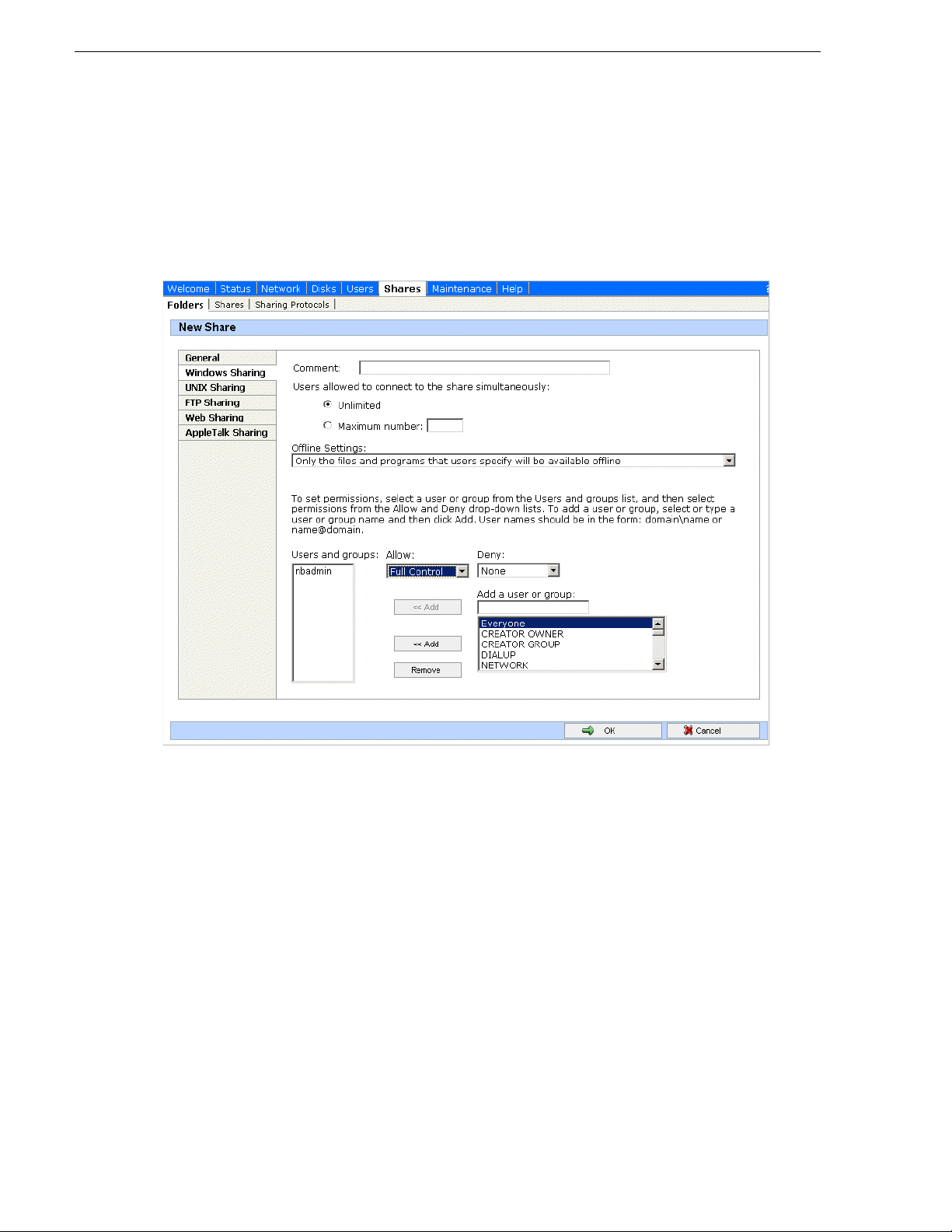
Chapter 3 Configuring the system
d. Click Share Folder.
e. Enter the following:
Share name: media
f. Click
Windows Sharing. After a pause, the Windows Sharing tab opens.
g. User privileges for the me dia folder should be as foll ows:
Everyone — Read only access
nbadmin — Full Control
h. Click
OK.
10.Close the NAS configuration pages.
Verify NAS access
Verify Proxy NAS access from producti on network mac hines, which a re machines of
the following types:
• MediaFrame server
• Advanced encoder
•SmartBin encoder
To verify access, from each production network machine do the following:
48 Aurora Browse Installation and Configuration Guide September 22, 2006
Page 49

1. Open Windows Explorer and navigate to the media direc tory on the NAS. You can
***** Contact Grass Valley
Support for password.
do this with the following path:
\\root-nb-nas-1\Media
2. Verify basic read/write capabilities by creatin g, modifying, and dele ting a simple
text file.
To verify access from client network machines, choose a machine on the Client
network that can represent a Aurora Browse client PC and that is convenient for
testing. From this machin e do the following:
1. Open Windows Explorer and navigate to the media direc tory on the NAS. You can
do this with the following path:
\\root-nb-nas-1\Media
2. Verify that Aurora Browse client PCs will have read only rights.
About the nbadmin account
The nbadmin account should be set up by default on Aurora Browse machines that
you receive from the factory. This account is critical for most Aurora Browse proxy
access, as explained in this section.
Prepare for core configuration stages
A local nbadmin account is required on the following machines:
• Proxy NAS machines
• Advanced encoder
•SmartBin encoder
•MDI server
• MediaFrame server
• Aurora DSM
• M-Series iVDR
• Profile XPS
•K2 systems
All NAS machines re quire t hat an nbadmin account with a password of
permission to the folder on the NAS that the encoders write to, and that the web
service running on the MediaFrame server reads from.
The basic principle is that any service that requires write access to the Proxy NAS
must run as the nbadmin account. This is a local machine account (NOT a domain
account). This includes all encoders, the MediaFrame server (which creates EDL files
on the Proxy NAS), the News MDI (which writes/deletes a temporary EDL file off of
the Proxy NAS), the Proxy MDI (which deletes files off of the Proxy NAS) and the
Profile MDI (which deletes temporary EDLs off of the Proxy NAS).
***** has
September 22, 2006 Aurora Browse Installation and Configuration Guide 49
On K2 systems and M-Series iVDRs, security is invoked, which requires
administrator privilege. This privilege comes from the nbadmin account, which is
another way the nbadmin comes into play on these devices.
Page 50

Chapter 3 Configuring the system
***** Contact Grass Valley
Support for password.
From a Windows networking perspective, when a user account is defined on a local
computer rather than a Domain Controller, the account is a “local” account, whose
complete name is <computer name>\<username>, rather than
<domain>\<username>. For example, with an encoder named Encoder1, a
MediaFrame server named Server1, and a NAS named NAS1, there are three separate
local accounts: Encoder1\nbadmin, Server1\nbadmin, and NAS1\nbadmin.
The Windows network automatically maps a local account from one computer onto
the local account of another computer—as long as both the account name and the
password are identical. To enable this mapping to occur, the W indows Domain
Controller “synchronizes” the local accounts on computers at the time they join the
Domain. Therefore , if the nbadmin account is added to the NAS machine after the
Windows NAS has joined the Windows Domain, this synchronizati on does not occur.
This should not be a problem on factory-prepared Aurora Browse machines, as they
come with the nbadmin account pre-configured. However, if the proper sequence is
not followed and the problem does occur, th e workaround is t o remove the NAS from
the Windows Domain and then re-add it immediately thereafter.
Accessing services
Software c omponents are distribu ted among th e machines that make up the system.
These software compone nts run as Windows services. A machine has the services that
correspond to the software components it hosts.
When you change the configuration for a particular software component thr ough the
configuration pages, you must restart that software component’s service to put the
changes into effect. Cl ick
Services
to access the services. All service names start with “Thomson…”, so they
Start | Settings | Control Panel | Administrative Tools |
group together in the services list.
Refer to “Ports and services mapping” on page 36 for a list of servi ces.
Accessing system configuration pages
Use Internet Explorer to browse to port 280 of a machine to access its configuration
pages. You must have administr ator permissi ons on the machine . For example, to log
on to the configuration pages on the MediaFrame server with administrator
permissions, use the following:
Username: root-nb-svr\nbadmin
Password: *****
The settings you find on a particular computer’s configuration pages depend on the
software installed on the computer. For example, if the Proxy MDI component is
hosted on a single-channel encoder, you find the Proxy Managed Device
configuration settings at port 280 of that single-channel encoder. However, if the
Proxy MDI component is hosted on a dedicated MDI server, you find the Proxy
Managed Device configuration settings at port 280 of the MDI server machine.
You can access a computer’s configuration pages as follows:
50 Aurora Browse Installation and Configuration Guide September 22, 2006
• From the local computer, use the following URL:
http://localhost:280
• For configurati on pages on the MediaFrame server, you can also open the Aurora
Page 51

Prepare for core configuration stages
Browse launch page and then click the Configuration link. To open the Aurora
Browse launch page, use the following URL:
http://localhost/nbui
The Aurora Browse launch page resides on the MediaFrame server only.
• From a network-connected computer, in the URL replace “localhost” with the
network name of the computer hosting the configuration pages. For example, to
access the configura tion pages or the Aurora Browse l aunch page on a MediaFrame
server named iron-nb-svr, use the following URLs:
http://iron-nb-svr:280
http://iron-nb-svr/nbui
You must have network access to open configuration pages. You can access all
Aurora Browse devices from the MediaFrame se rver. However, devices on the Clie nt
Network, such as a Aurora Browse clie nt PC, do not have access to all Auro ra Browse
devices. From an Aurora Browse cl ient PC you ca nnot acc ess devi ces that are on the
Production network only.
To access configuration pages, do the following:
Enter the URL to the configura ti on page at port 280 and press Enter.
Verify the machine name and IP address, to confirm that you are configuring
the correct machine. There can be multiple IP addresses for the different
networks.
Click links to open configuration pages.
Some pages use Active X controls that require special browser settings, such as the
following:
• In Internet Explore r, click
opens. Click
Security | Local intranet | Custom Level. The Security Settings dialog
Tools | Internet Options. The Internet Options dial og box
box opens. Under “Initialize and Script ActiveX Controls not marked as safe”,
Enable.
click
September 22, 2006 Aurora Browse Installation and Configuration Guide 51
Page 52

Chapter 3 Configuring the system
Stop services
Before beginning your initial core configuration stages, you must make sure all
Thomson services a re stopp ed. This p revents the c reation of corrupt database reco rds
and other errors that result from a partially configured system.
Go to each machine and make sure all “Thomson…” services are stopped and set to
manual, as describe d i n “Accessing servic es” on page 50. Then, when you configure
each stage, you start the appropriate se rvices to put the sett ings into effect. Th is brings
the system on-line in an ord erly f ashion t hat al lows y ou to veri fy syst em in terac tions
and identify configuration problems.
NOTE: It is especially important that the Rules Wizard is not running during
configuration stage tests that create media files. When a test media file is created,
the Rules Wizard can trigger the creation of various types of proxy media. This
causes problems because the partially configured system is unable to handle the
proxy correctly.
52 Aurora Browse Installation and Configuration Guide September 22, 2006
Page 53

MediaFrame stage
MediaFrame components make up the core platform on which Aurora Browse runs.
The primary MediaFrame components that you need to configure are as follows:
• ASK — The ASK software component runs on the MediaFrame server. It is the
central registry for all the software components of the sys t em. As softw are
components carry out t asks in a function ing system they regular ly refer to the ASK
component to establish communication and exchange commands and data. The
configuration pages also refer to the ASK component to populate fields and lists
and to validate the values you enter as you configure the system.
MediaFrame stage
MDI Server
info
Production Network
info
MediaFrame
Server
• MDIs — Devices have Managed Device Interfaces (MDIs) which represents the
device’s assets in a way that is understandable by the other components of the
system. This allows the MediaFrame server to coordinate the activity of the system.
In this configuration stage you add a MDI server and then set up logical names for
software components that manage devices. This brings the machines of your system
on-line as managed devices.
To do the basic configuration and testing of the MediaFrame software components,
do the following, as appropriate for the devices in your system:
• “Configure Media Frame ASK: Register components” on page 54
• “Prepare MDI server” on page 56
• “Configure ASK Location: MDI server” on page 57
• “Configure Proxy MDI” on page 58
• “Configure K2 MDIs” on page 59
• “Configure Profile MDIs” on page 60
• “Configure News MDIs” on page 61
• “Configure M-Series MDIs” on page 62
• “Test: MediaFrame stage” on page 63
September 22, 2006 Aurora Browse Installation and Configuration Guide 53
Page 54

Chapter 3 Configuring the system
Configure Media Frame ASK: Register components
Do not modify
Advanced
Basic
http://localhost:280 MediaFrameCore ASK
Open this configuration page locally on the MediaFrame server machine.
!!
!
!
!
!
!
!
!
!
All Domain names in the MediaFrame system mu st be ide nt ic al.
Port 9010 is required. See “Ports and servic es m apping” on page 36.
Saves changes. Changes are lost if you leave the configu r at io n page without
updating.
For the following settings, use the tab le bel ow. A dd each MDI and/or Encoder
required by your system
Click to add an MDI/Enco der.
Lists currently added MDIs and Enco ders.
Checks MDIs. Refer to “Test: MediaFra me stage” on page 63
Deletes the currently selected MDI or Encoder.
Always click
Update… buttons after making changes
To put changes into effect, start or restart the ASK service on the MediaFrame
server.
For the conventions mentioned in the following table, refer to “MDI and Encoder
logical names convention” on page 33
When you add an
MDI or Encoder
logical name for
this type of
machine/device…
A K2 Storage
System (SAN)
a
K2 Media Client Internal storag e
(stand-alone)
Select “MDI/
Encoder
Type”…
Enter “MDI/
Encoder
Name”…
K2 As per
convention.
K2
Enter “Host Name or
IP”…
Hostname of the machine
hosting the K2 MDIs.
Typically the MDI Server.
Enter “Port”… Comments
9160 - 9169 These are process port s, as
explained in “Ports and
services mapping” on
page 36. Assign numbers in
an intentional sequence, so
they are easy to match in
“Configure K2 MDIs” on
page 59.
54 Aurora Browse Installation and Configuration Guide September 22, 2006
Page 55

MediaFrame stage
When you add an
MDI or Encoder
logical name for
this type of
machine/device…
Open SAN ProfilebProfile As per
Stand-alone Profile Pro file
M-Series MSeries Hostname of the machine
Aurora Edit News As per
NTFS storage on
Windows machines
Advanced encoder Advanced
Select “MDI/
Encoder
Type”…
NTFS
Encoder
Enter “MDI/
Encoder
Name”…
convention.
convention.
NTFS1, as per
convention.
As per
convention
Enter “Host Name or
IP”…
Hostname of the machine
hosting the Profile MDIs.
Typically the MDI server
hosting the M-Series
MDIs. Typically the MDI
server
Hostname of the machine
hosting the News MDIs.
This must be the DSM.
MediaFrame server
hostname, as the server is
the required NTFS MDI
host.
Advanced encoder
hostname
Enter “Port”… Comments
9130 - 9139 These are process port s, as
9140 - 9149 These are process port s, as
Leave field
blank. Correct
port number is
automatically
entered on
“Add MDI”.
Refer to “Ports
and services
mapping” on
page 36 to
verify.
explained in “Ports and
services mapping” on
page 36. Assign numbers in
an intentional sequence, so
they are easy to match in
“Configure Profile MDIs” on
page 60.
explained in “Ports and
services mapping” on
page 36. Assign numbers in
an intentional sequence, so
they are easy to match in
“Configure M-Series MDIs”
on page 62.
Proxy Proxy PROXY1, as
Archive device … Archive ARCHIVE1,
SmartBin Encoder SmartBin
a.
For a K2 Storage System, the MDI manages one of the connected K2 Media Clients. As pe r co nvention, name the MDI for the K2
Storage Syst em.
b.
Enter only one Profile per Ope n SA N . As per convention, name the MDI for the O pe n SA N , rat her than for the Profile.
Encoder
per
convention.
as per
convention.
As per
convention.
Hostname of the machine
hosting the Proxy MDI.
Typically the MDI server.
Hostname of the machine
hosting the archive MDI
SmartBin encoder
hostname
NOTE: The MediaFrame server must host the NTFS MDI.
The ASK settings page registers the logical names for the MDIs and Encoders
required by your MediaFrame system with the ASK soft ware component, which runs
on the MediaFrame server.
Note the following distinction when entering “Ho stname or IP”:
• For MDIs (K2, Profile, M-Series, News, Proxy, NTFS, Archive) enter the
hostname of the machine hosting the MDI software component, rather than the
hostname of the machine being managed by the MDI.
• For Encoders (Advanced Encoder, SmartBin Encoder) enter the hostname of the
encoder itself.
September 22, 2006 Aurora Browse Installation and Configuration Guide 55
Page 56

Chapter 3 Configuring the system
Prepare MDI server
A machine that hosts a MDI service takes the role of a MDI server. Refer to the
following to identify the machines in your MediaFrame system that take the role of
MDI server, and make sure that the appropriate MDI services are installed. Refer to
“About Aurora Browse software” on page 24.
Dedicated MDI server — For medium to large MediaFrame systems , most MDI
services are on a stand-alone MDI server machin e, to ensure sy stem performance. If
your system has a dedi cated MDI server, it comes from the fact ory with MDI serv ices
installed, so you do not need to do any further installation. The MDI server requires
only network communication in preparation for its use in the MediaFrame system.
MediaFrame server as MDI server — For small Medi aFrame systems, the MDI servi ces
can reside on the Media Frame server. The MediaFr ame server comes from the f actory
with MDI service instal led, to support thes e smaller syste ms, so you do not need t o do
any further installation. The MediaFrame server also has the NTFS MDI service
installed, as it is required to run on the server, regardless of the size of the system.
DSM server as MDI server — For all systems, the News MDI must be hosted on the
DSM. You must install the News MDI on the DSM.
56 Aurora Browse Installation and Configuration Guide September 22, 2006
Page 57

Basic
Configure ASK Location: MDI server
Do not modify
Advanced
http://localhost:280 ASK Location
MediaFrame stage
Access this page locally on the MDI server.
!
!
!
Enter the name of the MediaF r ame server
Port 9010 is required. See “Ports and serv ices mapping” on page 36.
Saves changes. Changes are lost if you leave the configu r at io n page without
updating.
Always click
It is not necessary to restart a service to put these settings into effect.
Update… buttons after making changes
This page tells t he MDI server where to look for the ASK service, which runs on the
MediaFrame server. The function of the ASK is to store the location of the software
components in the system, so the components can find one another.
September 22, 2006 Aurora Browse Installation and Configuration Guide 57
Page 58

Chapter 3 Configuring the system
Configure Proxy MDI
Do not modify
Advanced
Basic
http://localhost:280 Managed Devic es Proxy MDI
Access this page locally on the MDI server.
!
!
!
!!
!
!
!
a.
You can define multiple locations on a single NAS machine, but for
each locati o n y o u must enter the complete pa th.
This page configures the Managed Device Interface (MDI) for the NAS machines that
store the low-res proxy. The system depends on the Proxy MDI to make pro xy visible
across the system.
All Domain names in the MediaFrame system must be identical.
Must be set to PROXY1, as per convention.
Port 9110 is required. See “Po rts and services mapping” on page 36.
Saves changes. Changes are l ost if you leave the configuration page without
updating.
For each Proxy NAS machine, enter the UNC path to the “Media” folder. This
is the location to which the system writes the proxy media.
Click to add as a location.
Lists the currently added locations. You can add multiple locations. You should
have one or more locations listed for each NAS machine.
Removes the currently selected location.
Always click
To put changes into effect, start or restart the Proxy MDI Service on the MDI
server.
Update… buttons after making changes
a
For the Proxy MDI, there is but one managed devic e, with the logical name PROXY1.
This managed device can hav e multiple locatio ns. The Media di rectory on each NAS
machine is entere d as a locati on. Other di rectories can be enter ed as locati ons as well.
In this way the Proxy MDI knows where to look for the low-res proxy.
58 Aurora Browse Installation and Configuration Guide September 22, 2006
Page 59

Basic
Configure K2 MDIs
Do not modify
Advanced
http://localhost:280 Managed Devices K2 MDI
MediaFrame stage
Access this page locally on the MDI Server.
!
!
!
!
!
!
!!
!
!!
!
Select a K2 MDI.
Increment 9160-9169 so each K2 MDI has a unique process port.
Enter a stand-alone K2 Media Client or the one K2 Media Client on a K2
Storage System.
Click to add as an existing managed device.
Verify the MDIs currently on-l in e.
Click to remove the selec ted m an age d device.
The following settings specify K2 systems to which assets can be transferred.
Select the MDI for a K2 system to which assets can be transferred.
Hostname of the K2 system specified above.
Click to add as a transfer target. This makes the K2 system available for
selection from th e Aurora Browse applic at ion as a transfer desti nation.
K2 systems capable of receiving a transfer.
Click to remove the selected transfer target.
To put changes into ef fect, start or restart K2 MDI Service o n t he MDI Server.
This page configures the Managed Device Interface (MDI) for a stand-alone K2
Media Client or the one K2 Media Client on a K2 Storage System (SAN).
MediaFrame depends on the K2 MDI to make K2 assets visible across the system.
As you configure th e K2 MDI make s ure t hat you assoc iate t he K2 MDI a nd K2 host
names correctly.
Multiple K2 MDIs run on a single machine (the MDI Server), but they each need their
own process port number. For this purpos e, enter increment ing numbers 9160 - 9169
in the “Port” field. The MDIs and their port numbers must match set tings as in
“Configure Media Frame ASK: Register components” on page 54. To make th e
configurations eas ier t o read for t rouble shooti ng pu rposes , add MDIs seq uentiall y so
there is a correlation between the port number and any number in the MDI name.
For K2 systems, add transfer targets as follows:
• For a K2 Storage System (SAN), the hostname of a K2 Media Server that has the
role of FTP server.
• For a stand-alone K2 Media Client, the hostname of the K2 Media Client
• Hostname of an Aur ora FTP server. This i s required for Auror a Transfer to suppor t
K2/Aurora transfers .
September 22, 2006 Aurora Browse Installation and Configuration Guide 59
Page 60

Chapter 3 Configuring the system
Configure Profile MDIs
Do not modify
Advanced
Basic
http://localhost:280 Managed Devices Profile MDI
Access this page locally on the MDI server.
!!
!
!
!
!
!
!!
!
!
!
!
!
!
Port 9100 is required. See “Po rts and services mapping” on page 36.
All Domain names in the MediaFrame system must be identical.
Saves changes. Changes are l ost if you leave the configuration page without
updating.
Select a Profile MDI.
Enter the hostname of the Pro fi le for the MD I sel e cted above.
For Open SAN systems, enter here the names of the other Profile XP systems
on the Open SAN that are managed by this MDI. Separate hostnames with
commas.
The time that the Profile MDI waits be f ore it informs the MediaFrame system
that a clip has finished recording. Leave at 2.
Automatically increments so each Profile MDI has a unique process port.
Click to add as an existing managed device. For stand-alone Profile Media
Servers, add a MDI f or each one. For Open SAN P rofile Media Serve rs , a dd
only one MDI per Open SAN.
Verify the MDIs currently on-line.
Click to remove the sel ected managed device.
The following settings speci f y Prof il es to whic h asse ts can be tra nsferred via
Fibre Channel from other Profiles. Thi s is used by Conform-To-Air EDL and
other Fibre Channel transfers. Refer to “Configure Profile MDI: Conform to air
settings” on page 83.
Select the MDI for a Profile to which assets can be transferred.
Hostname of the Profile specified above.
Click to add as a transfer target. This makes the Profile available for selection
from the Aurora Browse applicatio n as a transfer destinati o n.
Profiles capable of recei ving a Fibre Channel transfer .
!
Click to remove the selected transfer target.
Always click
To put changes into effect, start or restar t Profile MDI Se rvi ce on the MDI
server.
Update… buttons after making changes
This page configures the Managed Device Interfaces (MDI) for the Profile Media
Servers. As you add Pro file MDIs make sure that you associate Profile MDIs and
Profile host names correctly.
Multiple Profile M DIs run on a single m ach ine (the MDI server ), b ut they each need
their own process port number. For this purpose the “Port” field automatically
increments. To use the automatically incremented port numbers, make sure you add
Profile MDIs in the correct sequence. You can also manually ent er port numbers. The
MDIs and their port numbers must match settings as in “Configure Media Frame
ASK: Register components” on page 54.
For configuring the basic MediaFrame stage, do not yet configure transfer targets.
60 Aurora Browse Installation and Configuration Guide September 22, 2006
Page 61

Basic
Configure News MDIs
Do not modify
Advanced
http://localhost:280 Managed Devi ces News MIDI
MediaFrame stage
Access this page locally on the DSM.
!
!
!
!!
!!
Select a News MDI.
!
Port 9150 is required. See “Po rts and services mapping” on page 36.
The time that the News MDI waits before it informs the MediaFrame system
that a clip has finished recording. Leave at 2.
Enter the machine that hosts the Auro ra Edit database (the DSM).
Enter the machine that hosts the conform service. Typically the Conform
Server.
Leave blank or enter UNC path to shared storage. See below.
Saves changes. Changes are l ost if you leave the configuration page without
updating.
Always click
To put changes into effect, start or restart News MDI Service on the MDI
server.
Update… buttons after making changes
This page configures the Managed Device Interface (MDI) for the AuroraShare
system. MediaFrame depends on the News MDI to make News assets visible across
the system.
The V: drive must be ma pped on the m achine that hosts the News MDI. By
convention, the DSM hosts the News MDI.
The NAS Shared Location can be left blank for most systems. An example of a system
for which the path must be entered is a AuroraShare NAS system whose DSM (the
News MDI host) has been upgraded to Windows 2003 Server. The path is required
because of enhanced security in the Windows 2003 Server operating system.
As you configure the News MDI make sure that you associate the News MDI and
News host names correctly.
September 22, 2006 Aurora Browse Installation and Configuration Guide 61
Page 62

Chapter 3 Configuring the system
Configure M-Series MDIs
Do not modify
Advanced
http://localhost:280 Managed Devices MSeries MIDI
Basic
Access this page locally on the MDI server.
!
!
!
!
!
!
!
!
!
!
!
Select a M-Series MDI.
Automatically increments so each M- S eries MDI has a unique proc ess port.
Enter the M-Series managed by the MD I.
Click to add as an existing mana ged device.
Verify the MDIs currently on-line.
Click to remove the sel ected managed device.
The following settings specify M-Series systems to which assets can be
transferred.
Select the MDI for a M-Series system to which ass ets can be transferred.
Hostname of the M-Series system specified above.
Click to add as a tr an s f er target. This mak es the M-Series syst em a vailable for
selection from the Aurora Browse application as a transfer destination.
M-Series systems capable of receiving a transfer.
Click to remove the selected transfer target.
Always click
To put changes into effect, start or restart M-Series MDI Service on the MDI
server.
Update… buttons after making changes
This page configures the Managed Device Interface (MDI) for the M-Series iVDR.
MediaFrame depends on the M-Series MDI to make M-Series assets visible across the
system.
As you configure the M-Series MDI make su re that you associate the M-Series MDI
and M-Series host names correctly.
Multiple M-Series MDIs run on a single machine (the MDI server), but they each
need their own process port number. For this purpose the “Port” field automatically
increments. To use the automatically incremented port numbers, make sure you add
M-Series MDIs in the correct sequence. You can also manually enter port numbers.
The MDIs and the ir port number s must m atch se ttings as in “Configure Media Frame
ASK: Register components” on page 54.
For M-Series systems, add transfer targets as follows:
• The hostname of each M-Series system that is a transfer target
• Hostname of a Aurora FTP se rver. Thi s is re quired for Auror a Transfer to suppor t
M-Series/Aurora transfers.
62 Aurora Browse Installation and Configuration Guide September 22, 2006
Page 63

Test: MediaFrame stage
The following test exercises system function ality exclusive to the M ediaFrame c ore
platform. A successful test verifies that the basic config urations ar e correct.
Run the test as follows:
MediaFrame stage
On the Ask Settings configuration page, click
system checks MDI mappings and dev ic es for inconsistencies. This can take several
minutes. A report is displayed.
Validate MDIs. The MediaFrame core
Make sure there are no e rr or s di spl ay ed. To troubleshoot errors, check the following :
• Make sure services are running
• Make sure you have configured the correct host name for the MDI service.
• Ping machines to verify network communication.
Checklist: MediaFrame stage
Use the following check list to verify that the basic configuration and testing of the
MediaFrame stage is complete.
" All logical MDI names and Encoder service names are registered with ASK.
" All machines taking the role of MDI server have the appropriate MDI services
installed and running.
September 22, 2006 Aurora Browse Installation and Configuration Guide 63
Page 64

Chapter 3 Configuring the system
SmartBin encoder stage
Before starting this configuration stage you should have a working Aurora Edit/K2
system that uses at leas t one SmartB in Encoder. In this role, the Smar tBin Encoder is
not yet being used as a Aurora Browse machine. Rather, it is just used to host the
SmartBins service. Ref er to SmartBins Instruction Guide.
For this configuration stage you configure the SmartBin encoder to work together
with the ingest vi deo ser ver, the Media sto rage and the Proxy NAS. MDI se rvices are
also required, as configured in the MediaFrame stage. Configuration pages and
procedures are the same for HD and SD Smartbin encoders.
The portion of the system configured and tested in this stage is illustrated by the
following diagram.
AV
info info
mpg
th/sb
AV
SmartBin Encoder
Refer to “System diagram - K2 storage” on page 12 for a view of the entire system.
To do the basic configuration and testing of the SmartBin, do the following:
1. “Configure ASK Location: SmartBin encoder” on page 65
2. “Configure Media Frame Core ASK: SmartBin encoder” on page 65
Ingest
Media
Server
!
AV
DSM
Production Network* (Gb)
Media
Storage
!
AV
MDI Server
info
info
MediaFrame
Server
mpg
th/sb
Proxy
NAS
3. “Configure SmartBin Encoder Control” on page 65
4. “Configure Proxy Asset (NAS): SmartBin encoder” on page 66
5. “Configure MPEG encoder: SmartBin encoder” on page 66
6. “Test: SmartBin encoder” on page 66
64 Aurora Browse Installation and Configuration Guide September 22, 2006
Page 65

Basic
Configure ASK Location: SmartBin encoder
Do not modify
Advanced
http://root-nb-sbe-n:280 ASK Location
SmartBin encoder stage
!
!
Basic
!!
!
This page tells the SmartB in en code r wher e to l ook for the ASK service, which runs
on the MediaFrame server. The function of the ASK is to store the location of
MediaFrame components.
Configure Media Frame Core ASK: SmartBin encoder
Make sure the SmartBin encoder is registered with the ASK software component with
a logical name, as explained in “Configure Media Frame ASK: Register components”
on page 54.
Configure SmartBin Encoder Control
Do not modify
Advanced
http://root-nb-sbe-n:280 SmartBin Encoder SmartBin Encoder Control
!
Enter the name of the MediaF r ame server
Port 9010 is required. See “Ports and serv ices mapping” on page 36.
Saves changes. Changes are lost if you leave the configu r at io n page without
updating.
Always click
It is not necessary to restart a service to put these settings into effect.
Port 9230 is required. See “Ports and serv ices mapping” on page 36.
Always click
Update… buttons after making changes
Update… buttons after making changes
!
!
!!
!
!!
Select the News MDI.
Expired assets are purged from the system after this many days. Defines the age
of the MPEG as s et after which it is automat ically deleted from the system the
next time the purge rule runs. Leave blank to never expire. Refer to “About
expired assets” on page 80.
Always click
Select the proxy formats th is SmartBin encoder creates.
Saves changes. Changes are lost if you leave the configu r at io n page without
updating
Always click
To put changes into effect, start or restart the Thomson SmartBin Proxy Transfer
service on the SmartBin encoder.
This page configures the SmartBin encoder.
Update… buttons after making changes
Update… buttons after making changes
September 22, 2006 Aurora Browse Installation and Configuration Guide 65
Page 66

Chapter 3 Configuring the system
Configure Proxy Asset (NAS): SmartBin encoder
Do not modify
Advanced
Basic
http://root-nb-sbe-n:280 SmartBin Encoder Proxy Asset Information
!
!
!!
a.
PROXY1 can have multiple folders (on multiple machines)
defined as locations for proxy files. These locations are defined
on the Proxy MDI configuration pa ge .
b.
This location is us ed w hen in Rules, Prox y S torage Location is
blank (*).
This page specifies the default location (on a NAS machine) in which the SmartBin
encoder places the MPEG and storyboard proxy it creates.
When this page opens and when you click a
with valid information as currently defined on the Proxy MDI settings page.
Configure MPEG encoder: SmartBin encoder
Do not modify
Advanced
Basic
http://root-nb-sbe-n:280 SmartBin Encoder MPEG Encoder
There is but one logical Proxy Managed Device in the syst em , named
PROXY1.
Select the path to the fold er (\Med ia) on the NAS (or oth er stor age lo cati on)
that receives th e MPE G th is encoder creates.
Validates the current configurations with the Proxy MDI settings and saves
changes. Changes ar e lost if you leave the configuration page wi th out
updating.
Always click
To put changes into effect, start or rest art the SmartBin Pr oxy Transfer
service on the SmartBin encoder.
a
b
Update… buttons after making changes
… button, fields and lists are populated
!
!
!
Leave at default of 100 0000.
The MPEG encoder audio output. Adjust to calibrate Advanced Edit audio, or
to improve the quality of th e de sktop audio (i.e. if the source is 'too hot')
Saves changes. Changes are lost if you leave the configu r at io n page without
updating.
Always click
Restart the Thomson Proxy Transfe r service on the Advanced encoder.
Update… buttons after making changes
This page co nfigures the p arameters the encoder uses when it creates the MPEG
proxy.
Test: SmartBin encoder
On the Aurora Browse launch pag e, the “Smart Bin Encoder St atus” page displays the
status of all Smart Bin Encoders in the system. This page displays the list of all jobs
attempted by the Smart Bin Encoders. For each job, the following are provided:
- encoder name,
- the source and destination file names,
- the time the job was run,
- job status (with error information if the job was unsuccessfu l), and
66 Aurora Browse Installation and Configuration Guide September 22, 2006
Page 67

SmartBin encoder stage
- job completion percentage (if job is currently running)
Check the Smart Bin Encoder Status page as you run the following test.
The following test exercises system functionality exclusive creating MPEG and
storyboard proxy fr om a high-re s sou rce cl ip. A succe ssful test verif ies th at the b asic
configurations are correct.
ASK configuration, as in “MediaFrame stage” on page 53, is required for this test.
Test description: Trigger proxy creation by placing high-res material in the location
monitored by the SmartBin Encoder.
Run the test as follows:
1. Make sure that the system is not in use.
2. Start the Thomson Resolver service and the Thomson Metadata service on the
MediaFrame server.
3. Start the Thomson SmartBin Proxy Transfer service on the SmartBin encoder.
4. Click
5. Use Ingest Station to record to a SmartBin.
6. Watch Event Viewer and verify that the MPEG and storyboard proxy are created
Start | Programs | Thomson | Event Viewer to open Event Viewer.
and copied to the proxy NAS. Also verify that the high-res media goes to the K2
high-res media storage.
Checklist: SmartBin stage
Use the following check list to verify that the basic configuration and testing of the
SmartBin en coder is complete.
" When high-res material appears in the location monitored by the SmartBin
encoder, MPEG and/or storyboard proxy are created.
" SmartBins Service writes to K2 system.
" SmartBin encoder writes to NAS
September 22, 2006 Aurora Browse Installation and Configuration Guide 67
Page 68

Chapter 3 Configuring the system
Advanced encoder stand-alone stage
For this configuration stage you configure and test one Advanced encoder and one
Proxy NAS to work together. The Advanced encoder creates storyboard and MPEG
proxy. Configuration pages and procedures are the same for HD and SD Advanced
encoders.
The portion of the system configured and tested in this stage is illustrated by the
following diagram.
Production Network
th/sb
Advanced
Encoder
mpg
mpg
th/sb
Proxy
NAS
Refer to “System diagram - K2 storage” on page 12 for a view of the entire system.
To do the basic configurat ion and testing of a Advanced encoder stand-alone, do the
following:
1. “Configure ASK Location: Advanced encoder” on page 69
2. “Configure Advanced Encoding Control” on page 70
3. “Configure Proxy Asset (NAS): Advanced encoder” on page 72
4. “Configure MPEG encoder: Advanced encoder” on page 72
5. “Test: Advanced encoder stand-alone stage - high-res source” on page 72
6. “Test: Advanced encoder stand-alone stage - MPEG proxy source” on page 74
68 Aurora Browse Installation and Configuration Guide September 22, 2006
Page 69

Basic
Configure ASK Location: Advanced encoder
Do not modify
Advanced
http://root-nb-adv-n:280 ASK Location
Advanced encoder stand-alone stage
!
!
!
Enter the name of the MediaF r ame server
Port 9010 is required. See “Ports and serv ices mapping” on page 36.
Saves changes. Changes are lost if you leave the configu r at io n page without
updating.
Always click
It is not necessary to restart a service to put these settings into effect.
Update… buttons after making changes
This page tells the Advanced encoder where to look for the ASK service, which runs
on the MediaFrame server. The function of the ASK is to store the location of
MediaFrame components.
September 22, 2006 Aurora Browse Installation and Configuration Guide 69
Page 70

Chapter 3 Configuring the system
Configure Advanced Encoding Control
Do not modify
Advanced
Basic
http://root-nb-adv-n:280 Advanced Encoder Advanced Encoding Control
!
!
!
!
!
!!
!
V
!
!
!
!!
a.
When you create a new clip name in the media database on th e K2
system, the encoder is notified and waits for the media file to
appear. Set this value to be the max imu m time allowed in your
workflow between the creation of a clip name and the
commencement of recording the clip.
b.
If the high-res stream for which t he e ncoder is creating proxy
material is interrupted, the encoder waits this long for the stream to
continue.
Port 9230 is required. See “Ports and servic es m apping” on page 36.
Always click
Usually th e Advanc ed Enc oder hos ts th e Aurora FTP se rvice, so en ter localhost.
Otherwise, enter the host name of the Auro ra FT P service.
Enter the maximum time the encoder waits for recording to begin after a clip is
created in the database. 60 seconds is the recommended setting.
Enter the maximu m time th e enco der waits for a break i n the media st ream to be
restored. 60 seconds is the recommended setting.
Click to add as a GXF server fo r th is encoder.
GXF servers currently added for this encoder.
Remove the currently selected GXF server
Refer to “Conf iguring Encoder Mode” on page 70 for the follow ing settings.
Select
additional proxy from an existing MPEG proxy source.
The MDI of the device on which the source resides.
The location of the source.
Saves changes. Changes are lost if you leave the configu r at io n page without
updating
Always click
To put changes into effect, start or restart the Thomson Proxy Transfer service
on the Advanced encoder.
Update… buttons after making changes
a
b
Material to create proxy from a high-res source. Select Proxy to create
Update… buttons after making changes
This page configures the connections between the Advanced encoder and the server
from which i t gets its media stream.
Configuring Encoder Mode
These settings allow you to set up the Advanced Encoder to generate proxy for
high-priority inges t or edited material. This dedicate d Advanced Encoder then only
runs scavenge operations when new material appears in a specific location. That
way you can be assured that your high-priority ingest or edited material is
immediately processed, even if there are multiple other lower priority scavenge
jobs that need to be done at the same time. Your other un-dedicated Advanced
Encoders can do the low priority jobs without interfering with the availability of
the dedicated Advanced Encoders.
It is recommended that you dedicate at least one Advanced Encoder to scavenge
70 Aurora Browse Installation and Configuration Guide September 22, 2006
Page 71

Advanced encoder stand-alone stage
newly edited material that you place in an “Outbox” folder. Refer to “Design
considerations - Aurora Browse with Aurora Edit” on page 12.
To dedicate the Advanced Encoder to a folder, do the following:
• For MDI Type, select
Material.
• For MDI Name, select a valid MDI Name (other than “*”). To sca venge material
in an “Outbox” folder on a K2 Storage System, select the News MDI.
• For Storage Location, select a valid Storage Location (other than “*”). To
scavenge material in an “Outbox” folder on a K2 Storage System, select the
specific folder.
You can dedicate the Advanced en code r to a par ti cu lar Prox y NAS locat ion . This
assumes that for a si ngle Proxy MDI (PROXY1 ) there are mul tiple NAS locat ions.
• To configure the Advanced encoder to process proxy media on all locations,
enter “*”.
• To configure the Advanced encoder to process proxy media on one location,
select that location as the Proxy Storage Location.
Configuration rules:
• If the MDI name is “*”, the Storage Location must be “*”.
• If the configur ation file is manu ally updated ( not recommended) to dis able both
Material Source and Proxy Source, the following occurs:
- Proxy Transfer Service will log an error message “Error: Both Scavenge
Mode and ISS Mode are disabled. This Encoder will not be able to do any
encoding” in the log.
- On the Advanced Encoding Control config uration page, red text “Error: Both
Scavenge Mode and ISS Mode are di sabled. Thi s Encoder wil l not be abl e to
do any encoding” is displayed.
September 22, 2006 Aurora Browse Installation and Configuration Guide 71
Page 72

Chapter 3 Configuring the system
Configure Proxy Asset (NAS): Advanced encoder
Do not modify
Advanced
Basic
http://root-nb-adv-n:280 Advanced Encoder Proxy Asset Information
!
!
!!
a.
PROXY1 can have multiple folders (on multiple machines)
defined as locations for assets. These locations are defined on the
Proxy MDI configuration pag e.
b.
This location is us ed w hen in Rules, Prox y S torage Location is
blank (*).
This page specifies the default location (on a NAS machine) in which the Advanced
encoder places the MPEG proxy and storyboard assets it creates.
When this page opens and when you click a
with valid information as currently defined on the Proxy MDI settings page.
Configure MPEG encoder: Advanced encoder
Do not modify
Advanced
Basic
http://root-nb-adv-n:280 Advanced Encoder MPEG Encoder
There is but one logical Proxy Managed Device in the syst em , named
PROXY1.
Select the path to the fold er (\Med ia) on the NAS (or oth er stor age lo cati on)
that receives th e MPE G th is encoder creates.
Validates the current configurations with the Proxy MDI settings and saves
changes. Changes ar e lost if you leave the configuration page wi th out
updating.
Always click
To put changes into effect, start or restart the Proxy Transfer ser vi ce on the
Advanced encoder.
a
b
Update… buttons after making changes
… button, fields and lists are populated
!
!
!
Leave at default of 100 0000.
The MPEG encoder audio output. Adjust to calibrate Advanced Edit audio, or
to improve the quality of th e de sktop audio (i.e. if the source is 'too hot')
Saves changes. Changes are lost if you leave the configu r at io n page without
updating.
Always click
Restart the Thomson Proxy Transfe r service on the Advanced encoder.
Update… buttons after making changes
This page co nfigures the p arameters the encoder uses when it creates the MPEG
proxy assets.
Test: Advanced encoder stand-alone stage - high-res source
The following test ex ercises Advan ced encoder functio nality for cr eating proxy usi ng
News high-res material as the source. A successful test verifies that the basic
configurations are correct.
Test description: New proxy types (MPEG, storyboard) are created from high-res
material and are transferred to a different location.
ASK configuration, as in “MediaFrame stage” on page 53, is required for this test.
72 Aurora Browse Installation and Configuration Guide September 22, 2006
Page 73

Advanced encoder stand-alone stage
NOTE: Run this test only in the stand-alone stage, with machines that have not yet
been added as managed devices (as in the + Server stage). Once the server is
connected, this test can result in corrupt database records.
Run the test as follows:
1. Make sure that the system is not in use.
2. Make sure the Rules Wizard Serv ice, Thomson Resol ver service, and the Thomson
Metadata service are off on the MediaFrame se rver.
3. On the Advanced encoder, click
Diagnostic Tools | Proxy Transfer Client
opens.
Start | Programs | Thomson | Aurora Browse |
. The Proxy Transfer Client application
4. Configure as follows to check the connection:
•Host:
localhost
•Port: 9230
5. Click Connect. Verify that the “…Updat e…” and “ …Transfer…” buttons bec ome
enabled, which means the connection is successful.
September 22, 2006 Aurora Browse Installation and Configuration Guide 73
Page 74

Chapter 3 Configuring the system
6. Configure as follows to define the source clip on the News hi-res storage:
• Source Type: Select
Material.
• MDI Name: Select the logical name of the News MDI.
• MDI Type: This should automatically fill in as
device/news
• Location: Select the bin on the News hi-res storage that holds the test material.
• Clip Name: Select the test clip.
• Clip Type: This should automatically fill in as
video/news.masterclip
7. Select the following to transfer/transcode proxy:
• MPEG-1
• Story Board
8. Click
Transfer (With Auto update). Watch the report in the State column to verify
that the proxy creation is successful. The proxy files are written to the location
configured on the Pr oxy Asset conf iguration page as “Defa ult File Sys tem Folder”.
9. Using Windows Explorer, verify the MPEG and storyboa rd proxy is created. Open
and play the MPEG clip. Validate video and audio.
Test: Advanced encoder stand-alone stage - MPEG proxy source
The following test exercises system functionality exclusive to configurations for
creating storyboard proxy from MPEG proxy. A successf ul test verifi es that the bas ic
configurations are correct.
Test description: Storyboard proxy is created from MPEG proxy.
ASK configuration, as in “MediaFrame stage” on page 53, is required for this test.
NOTE: Run this test only in the stand-alone stage, with machines that have not yet
been added as managed devices (as in the + Server stage). Once the server is
connected, this test can result in corrupt database records.
Run the test as follows:
1. Make sure that the system is not in use.
2. Make sure the Rules Wizard Service, Thomson Resolver servi ce, and the Thomson
Metadata service are off on the MediaFrame server.
74 Aurora Browse Installation and Configuration Guide September 22, 2006
Page 75

Advanced encoder stand-alone stage
3. On the Advanced encoder, click Start | Programs | Thomson | Aurora Browse |
Diagnostic Tools | Proxy Transfer Client
opens.
. The Proxy Transfer Client application
4. Configure as follows to check the connection:
•Host:
localhost
•Port: 9230
5. Click Connect. Verify that the “…Updat e…” and “ …Transfer…” buttons bec ome
enabled, which means the connection is successful.
6. Configure as follows to define the MPEG source on the NAS:
• Source Type: Select
Proxy.
• MDI Name: Select the logical name of the Proxy MDI.
• MDI Type: Select
device/proxy.
• Location: Select the directory on the NAS that holds the test proxy MPEG.
• Clip Name: Select the test clip.
September 22, 2006 Aurora Browse Installation and Configuration Guide 75
Page 76

Chapter 3 Configuring the system
• Clip Type: Select video/proxy.mpeg
7. Select the following to transfer/transcode proxy:
• Story Board
8. Click
9. Using Windows Explorer, verify that the storyboard test files were written to the
Transfer (With Auto update). Track progress in the State column unti l it
reports DONE. The proxy files are writt en to the locat ion configur ed on the Proxy
Asset configuration page as “Default File System Folder”
proper directory.
Checklist: Advanced encoder stand-alone stage
Use the following check list to verify that the basic configuration and testing of the
stand-alone Advanced encoder is complete.
" Advanced encoder is connected to NAS
" Encoder writes to NAS
" MPEG created
" MPEG playback with audio
" Storyboard files are created.
76 Aurora Browse Installation and Configuration Guide September 22, 2006
Page 77

Advanced encoder + Server stage
For this configuration stage you configure the MediaFrame server to work together
with the Advanced encoder a nd NAS from the Advanced encoder sta nd- al one s tag e.
MDI services are also r equired, as configured in the MediaFrame stage. Conf iguration
pages and procedures are the same for HD and SD Advanced encoders.
The portion of the system configured and tested in this stage is illustrated by the
following diagram.
Advanced encoder + Server stage
Aurora Ingest
AV
Ingest
Media
Server
!
Advanced
Encoder
infoinfo
AV
th/sb
mpg
Production Network
info
MDI Server
info
MediaFrame Server
mpg
Refer to “System diagram - K2 storage” on page 12 for a view of the entire system.
To do the basic conf igurati on and tes ting of the encod er plus server, d o the following :
1. “Configure Media Frame Core ASK: Advanced encoder” on page 77
2. “Configure Rules Automation: Advanced encoder” on page 78
3. “Test: Advanced encoder + Server stage - high-res source” on page 80
th/sb
Proxy
NAS
Configure Media Frame Core ASK: Advanced encoder
Make sure the Advanced enc oder’s Proxy Trans fer service is regi stered with th e ASK
software component with a logical name, as explained in “Configure Media Frame
ASK: Register components” on page 54.
September 22, 2006 Aurora Browse Installation and Configuration Guide 77
Page 78

Chapter 3 Configuring the system
Configure Rules Automation: Advanced encoder
Do not modify
Advanced
Basic
!
!
!
!
!
!!
!
http://root-nb-svr:280 Media Frame Core Rules Automation
!
!
The following settings defi ne t he creation of proxy assets.
Select
Material if this rule creates proxy from a high-res source. Select MPEG-1
if this rule creates additional proxy from an existing MPEG proxy source. Refer
to “About configurin g rul es” on page 79.
Select the MDI for the machine monitored by the Advanced encoder.
Enter the location on the machine that the system monitors for new material.
Note: You must use forward slashes for this path.
Select to als o monitor f or mater ial in fol ders nes ted in “MD I Storage Location ”.
Select the proxy types to be created by this rule. (MPEG-1 option appears only
if Source = Mate rial above.)
Must be PROXY1. (This option appears only if Sourc e = Material above.)
Enter the location. Ente r * so the system can use any NAS and keep proxy
assets toget h er.
Set all rules to Normal to ensure all are processed in the order r eceived. Hig her
or lower priority settings can caus e a de la y for the lower priority rules.
Select one or both. Refer to “About configuring rules” on page 79. (These
options appear only if Source = Material above.)
a
(This option appears only if Source = Material above.)
!
!!
!
!
!
!
a.
When the Rule specifies “*” as the Proxy Storage Location the
Default File S ys tem Folder is use d, as configured in “Configure
Proxy Asset (NAS): Advance d e ncoder” on page 72
Expired assets are purged from the system after this many days. Leave blank to
never expire. Refer to “About expired assets” on page 80. (This option appears
only if Source = Material above.)
Add Rule adds the above settings as a new Proxy Creation rule.
The
Update Rule button only appears if an existing rule is selected in the
Existing Rules box below, in which case the button puts into effect any changes
you have made to the existing rule.
Displays all currently added rul es. When a rule is selected, the options above
are automatically loaded with the settings for the selected rule. You can then
modify the rule and update it, or m odify the rule and add it as a new rule.
Removes the current ly s elected rule
Specifies how many ti mes the syste m retri es a faile d rule. Kee p this sett ing at 3
or below for most rules to prevent degradation of system perf ormance.
When a failed rule is retried, its priority can be changed in relation to other rules
currently being processed. Set to
Save Retry setting chan ges
Always click
You must start or restart the Thomson Rules Wizard service on the MediaFrame
server to put changes into effect , but if you are doing the initial conf ig ura ti on
of the Advanced enco der + Ser ver sta ge, d on’t s tar t the ser vic e u ntil ins tru cted
to do so in the Advanced encoder + S erver stage test.
Update… buttons after making changes
Increase to promote time ly processing.
This page defines the rules for an Advanced Encoder creating proxy.
To scavenge newly-edited material in an “Outbox” folder on a K2 Storage System,
for MDI Name, select the News MDI and location as in “Configure Advanced
Encoding Control” on page 70.
78 Aurora Browse Installation and Configuration Guide September 22, 2006
Page 79

The following sections explain rules.
About configuring rules
The Rules Automation Settings page dynamically offers the appropriate options
based on the currently selected source, as follows:
Rules when the source is high-res material
These rules create MPEG and storyboard proxy from high-res material. This is also
known as a “scavenge” operation. Depending on the desired behavior of the system
you may have to create mult iple r ules f or the MPEG crea tion. Th ere ar e two typ es o f
rules, as follows:
Create while Recording — This rule causes MPEG to be created while the system
•
is still enco ding the high-res material.
•
Recreate Proxy if Content is Modified — This rule will cause the system to delete the
proxy associated with high-res material if the material has its content modified. It
will then recreate the MPEG proxy for the material. This rule is normally
configured for K2 storage systems.
The following takes place by default with both these types of rules:
Advanced encoder + Server stage
• When the Rules Wizar d starts up, it tr averses a high-res de vice MDI to see if ther e
is any material tha t does not have MPEG prox y associated with it, accord ing to the
currently configured rules. The Rules Wizard will only check the system once after
startup to see if it needs to create any of this proxy.
• Storyboard e lements are used f or thumbnails , so in effect thu mbnails are ge nerated
by default.
Rules when the source is MPEG proxy
These rules create storyboards from MPEG proxy. Storyboard elements are used for
thumbnails, so in effect thumbnails are generated by default.
Tips for configuring rules
• Configure one rul e per fo lder or “loca tion”. Mul tiple overl apping rul es that ac cess
the same folder can produce looping behaviors and other unexpected results.
• If using SmartBin Encoders, don’t use Advanced Encoder rules for ingest.
September 22, 2006 Aurora Browse Installation and Configuration Guide 79
Page 80

Chapter 3 Configuring the system
Configure Asset Manager
Do not modify
Advanced
Basic
http://root-nb-svr:280 MediaFrame Core Asset Manager
!
!
!
The time period in minutes Asset Mana ger service waits before it runs again.
When you select this option, if proxy media is found for w hic h t here is no
counterpart high-res materia l, A sset Manager deletes all associated proxy.
Saves changes. Changes are lost if you leave the configu r at io n page without
updating.
Always click
Restart the Thomson Asset Manage r service on the MediaFrame server.
Update… buttons after making changes
When the Asset Manage r serv ic e runs i t loo ks fo r expi red as sets and o rphaned asset s
that should be purged from the system. It also maintains the assets currently in the
Resolver and if nece ssary initi ates the creat ion of p roxy to k eep asset s in sync h. This
page configures the frequency and rules by which the Asset Manager carries out its
processes.
About expired assets
When assets are created, they can be assigned a “MetadataExpire” date. This is the
value that you enter on the Rules Automation Setting configuration page or on the
SmartBin Encoder Control configuration page. The “MetadataExpire” date is set to
the current d ate p lus t he nu mber of “ Days t o Expi re As set”. If you do not set a “ Days
to Expire Asset” value, the asset will never be purged automatically.
The Asset Manager executes a periodic purge task that runs at the frequency (in
minutes) that you configure on the Asset Manager Settings configuration page,
starting from the last time the Asset Manager service is started. This task takes the
current time of day date/time stamp and compares it to the “MetadataExpire” date,
and if the date portion of the cur re n t ti m est amp is <= the “Meta dataExpire” date, the
Asset Manager will att empt to delete the asset . Thus, the actual purge pe riod can occur
up to a day earlier than expected.
Recommendation:
Set the “Days to Expi re Asset” to one mor e than required to ensure that ass ets ar e not
deleted sooner than required.
For example, if you want assets to reside in the system approximately (but not less
than) one day, the “Day s to Exp ire As set” v alue s hould b e set to 2. Th is wil l res ult i n
actual asset lifetimes between 24 and 72 hours in the system. If you require the
maximum period to be closer to 48 hours than 72, decreasing the Purge Period from
1440 (24 hours) to a smaller value should be effective.
Test: Advanced encoder + Server stage - high-res source
The following test exercises system functionality exclu sive to the rules for creating
MPEG proxy and storyboard proxy from high-res materia l. A successful te st verifies
that the basic configurations for the rules are correct.
Test descriptio n: Trigger rules by cr eating/modifying a hig h-res clip on the K2 storage
while the Rules Wizard service is off, then on.
80 Aurora Browse Installation and Configuration Guide September 22, 2006
Page 81

Advanced encoder + Server stage
Run the test as follows:
1. Make sure that the system is not in use.
2. Make sure the Thomson Rules Wizard service is off on the MediaFrame server.
3. Start the Thomson Resolver service and the Thomson Metadata service on the
MediaFrame server.
4. Click
5. On a K2 system, copy a clip into a bin monitored by the Advanced encoder.
6. On the MediaFrame server, start the Thomson Rules Wizard. Watch Event Viewer
7. On the K2 system, copy another clip into th e bi n. Watc h Eve nt Vi ewer and verify
8. In you have a “…if content is modified” rule confi gur ed for high-res clips, on the
9. If you have a “Create while recordin g” rule configured for high-res clips, on the K2
Start | Programs | Thomson | Event Viewer to open Event Viewer.
and verify that the MPEG and storyboard proxy are created for the clip.
that the MPEG and storyboard proxy are created for the clip.
K2 system, modify a clip (rename) in the bin. Watch Eve nt Viewer and ver ify that
the MPEG and storyboard proxy are created for the modified clip.
system, record a clip into a bin monitored by the Advanced Encoder. Watch Event
Viewer and verify that the MPEG and storyboard proxy are created (in real-time)
as the clip is recorded.
Checklist: Advanced encoder + Server stage
Use the following check list to verify that the basic configuration and testing of the
single-channel encoder plus MediaFrame server is complete.
" When the Rules Wizard starts up, rules work as configured for the creation of
MPEG and storyboard proxy.
" When a clip is ingested, rules work as configured for the creation of MPEG and
storyboard proxy.
" When a high-res clip is copied into a monitored bin, rules work as configured for
creation of MPEG and storyboard proxy.
" When a high-res clip is modified, rules work as configured for creation of MPEG
and storyboard proxy.
September 22, 2006 Aurora Browse Installation and Configuration Guide 81
Page 82

Chapter 3 Configuring the system
EDL Export, Save, Conform stage
For this configuration stage you configure the setti ngs for the following Edit Decision
List (EDL) features. These features are available in the Aurora Browse applicati on
when EDLs are created:
• Export — Exports an EDL to a pre-defined location.
• Save — Saves the EDL as an as set for future use.
• Conform — Creates a high-res asset that matches the EDL on a K2 system. This
functionality is available for M-Series iVDRs and Profile XP systems as well.
• Conform to Air — Creates a high-res asset that matches the EDL on one K2
system, then transfers the asset to another K2 system. This functionality is
available for M-Series iVDRs and Profile XP systems as well.
Conform server requirem ents are as fo llows:
• V:\ should be mapped to the share1 on the high-res storage system.
• Host table should have an entry for the K2 sys te m c onne cti on, as in the following
example:
192.168.18.8 iron-k2-1 iron-k2-1_he0
• If conforming to a M-Series the host table should have an entry for the M-Series
High Speed Ethernet connection, as in the following example:
192.168.20.8 iron-ivdr-1 iron-ivdr-1_he0
• If conforming to a Profile the host table should have an entry to the High Speed
Ethernet connection on the UIM, as in the following example:
192.168.18.61 iron-xp-uim-1 iron-xp-1-uim_he0
To do the basic configuration and testing of the EDL stage, do the following:
1. “Configure Profile MDI: Conform to air settings” on page 83
2. “Configure NTFS MDI” on page 84
3. “Configure Media Frame Core ASK: NTFS” on page 84
4. “Configure Conform Services” on page 85
5. “Configure Export Services” on page 86
6. “Configure Save EDL settings” on page 87
7. “Test: EDL stage” on page 88
82 Aurora Browse Installation and Configuration Guide September 22, 2006
Page 83

Basic
Configure Profile MDI: Conform to air settings
Do not modify
Advanced
http://localhost:280 Profile MDI
EDL Export, Save, Conform stage
Access this page locally on the MDI server.
!!
!
!
!
!
!
!!
!
!
!
!
!
!
Port 9100 is required. See “Po rts and services mapping” on page 36.
All Domain names in the MediaFrame system must be identical.
Saves changes. Changes are l ost if you leave the configuration page without
updating.
Select a Profile MDI.
Enter the hostname of the Pro fi le for the MD I sel e cted above.
Enter the hostname of the backup Profile.
The time that the Profile MDI waits be f ore it informs the MediaFrame system
that a clip has finished recording. Leave at 2.
Automatically increments so each Profile MDI has a unique process port.
Click to add as an existing managed device. For stand-alone Profile Media
Servers, add a MDI f or each one. For Open SAN P rofile Media Serve rs , a dd
only one MDI per Open SAN.
Verify the MDIs currently on-line. A listing for a single Profile MDI includes
the values from all four “Add Profile MDI” fields above.
Click to remove the selected managed device.
The following settings specify Profiles to which material can be transferred via
Fibre Channel from other Profiles. Thi s is used by Conform-To-Air EDL and
other Fibre Channel transfe rs.
Select the MDI for a Profile to whic h mat er ial can be transferred.
Hostname of the Profile specified above.
Click to add as a transfer target. This makes the Profile available for selection
from the Aurora Browse application as a transfer destinati on.
b
a
!
a.
Make sure th e P r o file name is e ntered just as it is in the host tabl e.
b.
Make sure th e P r o file name is e ntered just as it is in the host tabl e.
This page configures the Managed Device Interface (MDI) for the Profile Media
Servers that recor d and store t he high-res media. T he MediaFrame sy stem depends on
the Profile MDI to make high-res media assets visible across the system.
For the EDL stage, configure the settings related to the ED L Conform to air feature .
Specify one of more on-air Profiles as the targets to which conformed high-res clips
can be transferred for playout.
For other settings, refer to “Configure Profile MDIs” on page 60.
Profiles capable of recei ving a Fibre Channel transfer .
Click to remove the selected transfer target.
Always click
To put changes into effect, start or restar t Profile MDI Se rvi ce on the MDI
server.
Update… buttons after making changes
September 22, 2006 Aurora Browse Installation and Configuration Guide 83
Page 84

Chapter 3 Configuring the system
Configure NTFS MDI
Do not modify
Advanced
Basic
http://root-nb-svr:280 Managed Devices NTFS MDI
!
!
!
!
!
!
!
!
!
Name of NTFS MDI, as registered with ASK. Refer to “Configure Medi a
Frame ASK: Register com ponents” on page 54.
9115 required. See “Ports and se rvi ce s mapping” on page 36.
Port
Saves changes. Changes are lost if you leave the configuration page without
updating.
Machine (and folder) ma naged by the NTFS MDI. This must be a UNC path .
The machine must have NTFS storage. You can optionally specify the folder.
Adds the machine/folde r as manag ed by the NTFS MDI.
Lists currently added machines/folders accessible by the NTFS MDI.
Removes the currently selected machine/folder from the list.
Defines the types of files accessible by the NTFS MDI. Follow the example
syntax.
Adds the file-type as accessible the NTFS MDI.
Lists currently added file-types accessible by the NTFS MD I.
Removes the currently selec ted file-type from the list.
Always click
Restart the Thoms on NTFS MDI Se rvice on the MediaFra me server.
Update… buttons after making changes
This page specifies the machines, directories, and file types that the NTFS MDI can
access. The Aurora Brow se application make s these available as selections for saving
and managing assets, including EDLs.
• Enter a locati on for saving EDLs. Typic ally this would b e on a NAS machine, such
as \\root-nas-n\EDLs.
• Enter a location for temporarily saving EDLs as they are being conformed.
Typically this would be on the MediaFrame server, such as
\\root-nb-svr\TempEDL.
NOTE: Configure different locations for EDL operations. Do not use the same
locations for saving, temporary saving, conforming, and exporting EDLs.
• Enter a location for saving audio fil es. Typically this would be on a NAS machine,
such as \\root-nas-n\Audio.
•Enter xml-edl/xml and wav-audio/wav as a file-types.
Configure Media Frame Core ASK: NTFS
Make sure the NTFS MDI is registered with the ASK software component with a
logical name, as explained in “Configure Media Frame ASK: Register components”
on page 54.
84 Aurora Browse Installation and Configuration Guide September 22, 2006
Page 85

Basic
!
!
!
!
!
!
!
!
!!
Configure Conform Services
Do not modify
Advanced
http://root-nb-svr:280 Aurora Browse Application Conform Services
EDL Export, Save, Conform stage
When an EDL is conformed it is t empo raril y stor ed in th e loc atio n specif i ed
by the following settings.
Select the name for the NTFS MDI (NTFS1).
Enter a full UN C p ath to the directory (on a machi ne with NTFS stor ag e) in
which the EDLs are tempo rarily stored.
Saves changes. Changes are lost if you leave the configuration page without
updating.
The following setting s spec ify a me di a se rver used to conform an EDL.
Enter the label for display in the Aurora Browse application that identifies the
location to which the media is conf or me d.
Select the MDI for the machine that stores the hi-res material.
The machine managed by th is MDI is ty pica lly a p lay-t o-a ir med ia ser ver to
which Conform-to-Air hi gh-res assets are transferred.
Location (bin) o n the play- to-air mach ine where the Conform-to-Air high-res
asset is stored.
Select to make the EDL available to NewsQPro.
Add the service to conform EDLs.
b
a
!
a.
This directory must be shared so it can be ac cessed by the
MediaFrame server.
b.
This list is automatically populated by reading the volume and
bin names from the media servers indicated by “Target MDI
Name” above.
This page tells the Aurora Browse application where to store EDLs that are to be
conformed and specifies location to which EDLs are conformed. You can add
multiple machines, each of which is then available fo r selection fr om the Aurora
Browse application.
NOTE: Configure different locations for EDL operations. Do not use the same
locations for saving, temporary saving, conforming, and exporting EDLs.
For a Conform-To-Air ser vice, the resul tant high -res asset is transferre d to an On-Air
media server (usu ally a stan d-alon e syst em) for playo ut. You must d efine the Aur ora
Browse application display name, the media servers, and the locations to make this
type of Conf orm-to-Air service available in the Auro ra Browse application.
Currently added services a vai l abl e to conform EDLs. You can add services
using several machines, so that the y ca n be sele cted in the Aurora Browse
application whe n conforming an EDL.
Removes the currently selected EDL service.
Always click
Restart the Aurora Browse application to put changes into effect.
Update… buttons after making changes
September 22, 2006 Aurora Browse Installation and Configuration Guide 85
Page 86

Chapter 3 Configuring the system
Configure Export Services
Do not modify
Advanced
Basic
http://root-nb-svr:280 Aurora Browse Application Export Services
!
!
!
!
!
!
a.
If the Export Location button does not open a Browse dialog box,
enable the Internet Explorer setting “Initialize and Script
ActiveX Controls…”. Refer to “Accessing system configuration
pages” on page 50 for procedures.
b.
This directory must be shared so it can be ac c esse d by th e
MediaFrame server.
This page tells the Aurora Browse application the locations available for exporting
EDLs. You ca n add multiple locations, each of which is then available for select ion
from the Aurora Browse application. Name locations and add them according to
workflow ne eds.
Enter the label for display in the Aurora Browse application that identifies the
location to which ED Ls can be exported.
Select if EDLs are to be accesse d by A urora Edit.
Select the News MDI.
a
the directory to whi ch the EDLs are exported.b This should be a
Select
working folder, not an “In box” or “Outbox” folder. Refer to “Design
considerations - Aurora Browse with Aurora Edit” on pa ge 12.
Adds the location as an export location.
Currently added location available for exporting EDLs. You can add several
locations, so that they can be selected in the Aurora Browse application when
exporting an EDL.
Removes the currently selected location.
Always click
Restart the Aurora Browse application to put changes into effect.
Update… buttons after making changes
NOTE: Configure different locations for EDL operations. Do not use the same
locations for saving, temporary saving, conforming, and exporting EDLs.
86 Aurora Browse Installation and Configuration Guide September 22, 2006
Page 87

Basic
Configure Save EDL settings
Do not modify
Advanced
http://root-nb-svr:280 Aurora Browse Application Save EDL
EDL Export, Save, Conform stage
!
!
!
EDLs are sav ed to this location, usually a NAS machine .
After this many days, a saved EDL is del et ed . E nter 0 to never delete.
Saves changes. Changes are lost if you leave the configuration page without
updating.
Always click
Restart the Aurora Browse application to put changes into effect.
Update… buttons after making changes
This page tells the Aurora Browse application where to save EDLs and how long to
keep them in the system.
NOTE: Configure different locations for EDL operations. Do not use the same
locations for saving, temporary saving, conforming, and exporting EDLs.
September 22, 2006 Aurora Browse Installation and Configuration Guide 87
Page 88

Chapter 3 Configuring the system
Test: EDL stage
The following test exercises system function ality exclusive to the ED L
configurations. A successful test verifies that the basic configurations are correct.
Test description: Using the Aurora Browse application, create an EDL, then export,
save, and conform it.
Run the test as follows:
1. Make sure that the system is not in use.
2. Load a clip in the Aurora Browse application.
3. Mark in/out region of the cl ip and press the Inse rt t o Ti meline button to ad d t o the
timeline. Do this a couple of times with this and other assets.
4. Select Save from the timeline control. Enter and take note of the name used for
saving. The save should be successful.
5. Refresh the results list by clicking the Go button with no crit eria selected. The EDL
asset name should appear in the results list.
6. Select the Export button from the t imeline c ontrol. S elect a destin ation an d choose
export.
7. Select Conform from the timeline control . Enter and take note of the name used for
conforming. Select a target (not a Conform to Air target) and choose Conform.
8. Select Conform again from the timeline control. Enter and take note of the name
used for conforming. Select a Conform to Air target and choose Conform.
9. To verify export, go to the Aurora Edit system and chec k for the exported sequence
in the expected location.
Checklist: EDL stage
Use the following check list to verify that the basic configuration and testing of the
EDL functio nality is complete.
" EDL is created and saved.
" Saved EDL available as asset from Aurora Browse application
" EDL exports to specified location
88 Aurora Browse Installation and Configuration Guide September 22, 2006
Page 89

Archive stage
For this configuration stage you configure your archive MDI, high-res storage, and
the MediaFrame server to w ork together. This assumes that the archive devices are
already installed and connected.
The portion of the system configured and tested in this stage is illustrated by the
following diagram.
!
Production Network (Gb)
Media
Storage
(K2)
Archive stage
Archive
Aurora FTP Server
MDI Server
MediaFrame Server
To support archive functionality on the News/K2 system, you must install a unique
Aurora FTP on a platform somewhere in the system.
To configure and test the Archive stage, do the following:
1. “Add archive MDI” on page 90
2. “Verify archive preparations” on page 91
3. “Configure ASK Location: Archive MDI host” on page 95
4. “Configure Media Frame Core ASK: Archive” on page 95
5. “Configure Avalon Archive MDI” on page 96
6. “Configure FlashNet MDI” on page 97
7. “Configure DIVA MDI” on page 98
8. “Configure Archive Services.” on page 99
9. “Test: Archive stage” on page 99
September 22, 2006 Aurora Browse Installation and Configuration Guide 89
Page 90

Chapter 3 Configuring the system
Add archive MDI
The archive MDI software component runs as a service. The archive MDIs that are
available for the different types of archive devices are as follows:
• Avalon Archive MDI — runs as the Thomson Avalon Archive MDI service
• FlashNet MDI — runs as the Thomson FlashNet MDI service
• DIVA MDI — runs as the Thomson DIVA MDI service
The archive MDI software component must be installed on a network connected
computer. Similar to the other MDIs in the MediaFrame system, the archive MDI can
be installed on a MDI server or on the Medi aFrame ser ver, depe nding on th e size and
design of your system.
You can install the archive MDI software component from the MediaFrame server
installation program. Select the component for your archive from the Custom setup
page.
90 Aurora Browse Installation and Configuration Guide September 22, 2006
Page 91

Verify archive preparations
Be aware of the following when setting up for integration with an archive system:
• Devices support a limited number of concurrent transfers, as follows:
• A single Profile XP (either stand-alone or on a Open SAN system), provides a
maximum of four streams for concurrent transfers (via Fibre Channel).
• An internal s torage ( stand-alone ) K2 Media Client pr ovides a maximum of f our
streams for concurrent tr ans fer s.
• A K2 Media Server provides a maximum of eight streams for concurrent
transfers.
Keep this limit in mind when configuring the archive device for concurrent
transfers. If the archive is configured such that it can request more than the number
of supported streams simultaneously from any single system, the additional
transfers will error out.
For the type of a rchive d evice you use , check th e following to verify prope r operat ion
with the system.
Avalon archive preparations
Archive stage
Check the fo llowing on the machine wh ich runs Avalon IDM Softwa re (Archive):
1. Login to the machine and go to /avalon/aam/utils
2. Run stataam and verify all services running properly.
3. Make sure host tables are set correctly. Verify for the machine name/IP which IDM
will talk to.
4. If archiving from a Profile XP or Open SAN system, make sure the Fibe r channel
interfaces are configured so that Avalon IDM can talk to the Profiles.
Consider the following when preparing to integrate Avalon archive with Aurora
Browse:
• Avalon archive has no fix ed limit for co ncurrent transfers.
FlashNet preparations
Check the following on the machine which runs the FlashNet software:
1. Login to the machine.
2. If archiving from a Profile XP or Open SAN system, verify that you can telnet to
the Profile XP Ethernet IP address on port 8192 (telnet keystone2_le0
8192).
3. Verify that you can FTP from the FlashNet server to the h igh-r es storage machi ne:
• If archiving fro m a Profi le XP or Open SAN, verify tha t you can FTP from the
FlashNet server to the Profile on the Fibre Channel address and login as user
movie.
• If archiving from K2 stor age or AuroraShare NAS, verify that you can FTP from
the FlashNet server t o the K2 stor age or AuroraSh are NAS on Gigabit Ether net
and login as user vmfmovie.
September 22, 2006 Aurora Browse Installation and Configuration Guide 91
Page 92

Chapter 3 Configuring the system
4. Make sure the “FlashNet Socket Listener” a nd “FlashNet Automation” servic es are
up and running.
5. Use the FlashNet “Jukebox” application to test that a drive can be successfully
accessed from FlashNet. Refer to “User Guide for FlashNet running on Wind ows
NT and Windows 2000 platforms”.
Consider the following when preparing to integrate FlashNet with Aurora Browse:
• The FlashNet MDI does not take any user specified name for a full restore. The
clips are restored using the original clip name (from archive). The FlashNet MDI
does, however, allow a user specified name for a partial restore.
• If archiving from a Profile XP or Open SAN system, take the concurrent transfer
limit into consideratio n. FlashNet’s setting for concurrent tr ansfers applies
globally to all source/destination pairs. There is no setting on a server-by-server
basis. To make the setti ng for “maximum number of concurrent transf ers”, you use
a file named C:\.dtool_env where you can specify “API_MAX_BACKUPS” and
“API_MAX_RESTORES”. The following is an exampl e for an e ight drive system:
API_MAX_BACKUPS 2
API_MAX_RESTORES 4
This example specifies that two concurrent jobs could be used for automation
ingest into the archive, four concurrent jobs could be allowed for automation
restore of archive s, leaving two dr ives spare for emergency use or another function.
• The FlashNet MDI uses a fi le cache to support ass et functio nality. As t he FlashNet
device does not have any support for file system updates, the FlashNet MDI
assumes that the MDI is the only gateway to the entire FlashNet file system. Any
changes made outside the scope of the MDI will not be reflected in MDI
immediately.
• Renaming of an asset is not supported in FlashNet.
• The FlashNet server installation must have the GENERATE UNIQUE NAME
entry set to FALSE. Use Configurator.exe for FlashNet server configuration.
• A restore opera tion always default s to highest “Time Cri tical” priori ty and archive
operation defaults to “normal” priority.
DIVA preparations
Check the following on the machine which runs DIVA software:
1. Login to the machine.
2. Verify that you can FTP from the DIVA server to the machine with the high-res
online material:
• If archiving fro m a Profi le XP or Open SAN, verify that you can FTP from the
DIVA server to the Profile on the Ethernet IP address and login as user movie.
• If archivin g from K2 storage or AuroraShare NAS, verify that you can FTP fr om
the DIVA server to the K2 stora ge or AuroraShare NAS on Gigabi t Ethernet and
login as user vmfmovie.
Consider the following when preparing to integrate DIVA with Aurora Browse:
• The DIVA MDI does not ta ke an y user sp ecifi ed name fo r a fu ll re store . The cli ps
92 Aurora Browse Installation and Configuration Guide September 22, 2006
Page 93

Archive stage
are restored using the original name (from archive). The DIVA MDI does,
however, al low a user specified name for a partial restore.
• DIVA has no fixed limit for concurrent transfers.
• If archiving from a Profile XP or Open SAN system, take the concurrent transfer
limit into considerat ion. DIVA’s setting fo r concurrent trans fers applies to sp ecific
source/destination pairs. With the configuration utility/tool you can specify the
concurrency limit on a server-by-server basis.
• The DIVA MDI makes an the a ssumption that the MDI is the only gateway to the
entire DIVA file system. Any c hanges made out side the sc ope of the MDI will no t
be reflected in MDI immediately.
• Renaming of an asset is not supported in DIVA.
• A restore operation always defaults to highest “Time Critical” priority and an
archive operation defaults to “normal” priority.
• The source name specified in the DIVA configuration utility must be the same as
the host table name of the machine with high-res online material.
• If the DIVA server is reboot ed, the Thomson DIVA MDI service must be restart ed.
Refer to “Accessing services” on page 50.
Network connectivity - all archive types
To test network connectivity, ping all machines from all machines.
If archiving to/from K2 Storage or AuroraShare NAS, ping these machin es on the
GigaBit network:
• MediaFrame server
• Archive MDI host
• News MDI host
• The machine hosting the Aurora FTP service
• Archive machine
• The K2 storage or AuroraShare NAS system
If archiving to/from Profile XP/Open SAN systems, ping these machines on the
GigaBit network:
• MediaFrame server
• Archive MDI host
• Profile MDI host (MDI server)
• Archive machine
• All Profile XP or Open SAN systems from/to which media is archived/restored
If archiving to/from Profile XP/Open SAN systems, also use Fibre Channel IP
addresses and ping th ese machine s:
• Archive server
September 22, 2006 Aurora Browse Installation and Configuration Guide 93
Page 94

Chapter 3 Configuring the system
• All Profile systems from/to which media is archived/restored
94 Aurora Browse Installation and Configuration Guide September 22, 2006
Page 95

Basic
Configure ASK Location: Archive MDI host
Do not modify
Advanced
http://localhost:280 ASK Location
Archive stage
Open this page locally on the machine that hosts the Archive MDI.
!
!
!
Enter the name of the MediaF r ame server
Port 9010 is required. See “Ports and serv ices mapping” on page 36.
Saves changes. Changes are lost if you leave the configu r at io n page without
updating.
Always click
It is not necessary to restart a service to put these settings into effect.
Update… buttons after making changes
This page tells the Ar chi ve MDI h ost where to look for the ASK ser vi ce, which runs
on the MediaFrame server. If the Archive MDI host is a MDI server or other Aurora
Browse machine this configuration has likely already been done.
Configure Media Frame Core ASK: Archive
Make sure the A rchive MDI is registered with the ASK software comp onent, as
explained in “Configure Media Frame ASK: Register components” on page 54.
September 22, 2006 Aurora Browse Installation and Configuration Guide 95
Page 96

Chapter 3 Configuring the system
Configure Avalon Archive MDI
Do not modify
Advanced
Basic
http://localhost:280 Managed Devices Avalon MDI
Open this page locally from the Avalon Archive MDI host.
!
!
!
!!
!
!
!
!
Name of the Avalon Archive machine. Append -idm to the end of the name.
This name (with -idm appended) must also be in the host table.
!
!
9120. See “Ports and services mapping” on page 36.
Enter
Adds media to the clip to ensure correct long GOP structure. Leave at 2.
The number of archive device s controlled by the MDI.
Select if using partial res tore feature.
Saves changes. Changes are lost if you leave the configu r at io n page without
updating.
The following settings define FT P for a rchive sources/destinations.
Provided by Mana ged Device. Requires netsem configuration on
Select
Avalon. The remainder of this page is di sabled.
-ORSelect
Round-robin. Requires configuration in the following fields
Select the News MDI name.
Enter the hostn ame of th e machi ne hosti ng the Au rora F TP service. If mu ltiple
hostnames, enter with comma s sepa ra ting.
Adds a FTP server as a source/destination for archive operations.
Currently added FT P s ervers.
a
b
:
c
!
a.
With Avalon configuration, you define FTP Servers and load
balance when you configure netsem, so it is not necessary to enter
any information on this page .
b.
If you do not use Avalon configur ation, you must define FTP
servers and load balance on this page.
c.
This defines the load balancing. The order of servers entered here
is the order in which the MDI seeks an open channel for an archive
job.
Open this pa ge locally on the machine that hosts the Avalon Archive MDI software
component. In this example settings are shown for archiving to/from a AuroraShare
NAS. This page tells the Avalon Archive MDI where to look for FTP transfer of
high-res material.
Typically load balancing is configured using Round Robin on this page. If load
balancing is provided by the managed device, when configuring netsem, make sure
the netsem FTP server logical name matches the same FTP server MDI name.
Deletes the curren tly selected device.
Always click
To put changes into effect, start or restart the Thomson Avalon Managed
Device service.
Update… buttons after making changes
96 Aurora Browse Installation and Configuration Guide September 22, 2006
Page 97

Basic
Configure FlashNet MDI
Do not modify
Advanced
http://localhost:280 Managed Devices FlashNet MDI
Archive stage
Open this page locally from the FlashNet MDI host.
!
!
!!
!
!
!!
!
The name of the Flas hNet MDI.
!
9124. See “Ports and services mapping” on page 36.
Enter
Name or IP address of the FlashNet machine.
Saves changes. Changes are lost if you leave the configuration page without
updating.
The following settings define FT P for a rchive sources/destinations.
Load balancing settings are disabled as only Round Robin is supported.
Select the MDI name for the News MDI.
Enter the hostname of the machine hosting the Aurora FTP service.
Adds a FTP server as a source/destination for archive operations.
Currently added F TP s ervers.
Deletes the curren tly selected device.
Always click
Update… buttons after making changes
Open this page locally on the machine that hosts the FlashN et MDI software
component.
This page tells the FlashNet MDI where to look for FTP transfer of high-res material.
In this example settings are shown for archiving to/from a AuroraShare NAS. For K2
storage or AuroraShare NAS systems, archive transfers are handled by a single FTP
server.
September 22, 2006 Aurora Browse Installation and Configuration Guide 97
Page 98

Chapter 3 Configuring the system
Configure DIVA MDI
Do not modify
Advanced
Basic
http://localhost:280 Managed Devices DIVA MDI
Open this page locally from the DIVA MDI host.
!
!
!
!
!!
!
!
!
Name of the DIVA MDI.
9122. See “Ports and services mapping” on page 36.
Enter
!
!
Name of IP address of the DIVArchive machine.
The port at which DIVA Manager listens for any active connection. By default
this port is set to 9000.
Specify the name of the disk arrays that are currently c onfigured with the
DIVA system.
The timeout value that contro ls any commu nica tion with the DIVA man ager.
Default value is set to 180 seconds.
Saves changes. Changes are lost if you leave the configu r at io n page without
updating.
The following settings define FT P for a rchive sources/destinations.
Load balancing settings are disabled as only Round Robin is supported.
Select the News MDI name.
Enter the hostname of the machine hosting the Aurora FTP service.
Adds a FTP server as a source/destination for archive operations.
Currently added FT P s ervers.
a
!
a.
An array designates a collection of disks designated by their name
as they are declar ed in th e D IVA r chive configura tion.
Open this page locally on the machine that hosts the DIVA MDI software component.
This page tells the DIVA MDI where to look for FTP transfer of high-res media
assets. In this example settings are shown for archiving to/from a AuroraShare NAS.
For K2 storage or AuroraShare NAS systems, archive transfers are handled by a
single FTP server.
Deletes the curren tly selected device.
Always click
Update… buttons after making changes
98 Aurora Browse Installation and Configuration Guide September 22, 2006
Page 99

Basic
Configure Archive Services.
Do not modify
Advanced
http://root-nb-svr-n:280 Aurora Browse Application Archive Services
Archive stage
!
!
!
!
!
!
!
!
a.
Profile location lists are automatically populated by reading bins
and volumes, as in Media Mana ger, from the Profile whose MDI
is selected from the field above.
This page tells the Archive MDI where to place high-res assets as they are restored
from the archive device.
When you select “Enable Mirrored Destination…”, you can then enter the MDI and
location for the mirrored high-res system. This allows you to define the pair of
mirrored systems as a single restore location. When this single location is selected in
the Aurora Browse applicat ion, clips are rest ored or deleted on both high- res systems
simultaneously.
Enter name for restore location , for display in th e Aurora Browse application.
Select the MDI for the high-res system that gets the r es tored clips.
Select a location on the high-res system that gets the restored clips.
Select if restoring to mirrored high-res systems. This opens the following fields
for mirrored restore operations.
Select the MDI for the mirrored system that gets the restored clips.
Select a location on the mirrored system that gets the restored clips.
Click to add as a restore location.
Lists currently added restore lo cations.
Click to remove the currently selected restore location.
Restart the Aurora Brow se application to put chan ges into effect.
a
Test: Archive stage
The following test exercises archive functionality. A successful test verifies t hat the
archive configurations are correct.
Test description: Using the Aurora Browse application, archive and restore high-res
media.
Run the test as follows:
1. Make sure that the system is not in use.
2. From the MediaFrame server, open the Aurora Browse application.
3. From the
application interface.
4. On the
5. On the
• Modify Group Membership
• Archive Selected Asset
September 22, 2006 Aurora Browse Installation and Configuration Guide 99
Find tab, load an asset. After a short pause, the asset appears in the
related tab, verify t hat onli ne media is listed as a Related Asset Component.
mgmt tab, verify the presence of the following links:
Page 100

Chapter 3 Configuring the system
The following links might also be present if the asset has already been archived:
• Restore Select ed Asset
• Delete from Archive
Archive and Restore links are not present if the user currently logged on is not
assigned Archive and Restore roles. See “Configure Aurora Browse Users” on
page 106.
6. On the
mgmt tab, click Archive Selected Asset. The Archive Selected Asset settings
are displayed on the tab.
7. Select an
Archive Group. This list comes fro m the archive device. This is the
location to which the high-res clip is archived.
8. Select
9. Click
10.On the Aurora Brows e launch page, click
delete online media following archive.
Submit, then Yes to confirm and Close.
Archive Status to track the progress of
the transfer. Once the transfer is complete the status reports as DONE and 100%.
11.On the Aurora Browse applicati on
Find tab, click Go. The asset list reloads. Verify
that an amber dot is listed with the asset. Select the asset to reload it, then click the
related tab and verify that offl ine media is now listed .
12.On the
mgmt tab, click Restore Selected Asset. The Restore Selected Asset settings
are displayed on the tab.
13.Select from the
Restore to Location list . Thi s is the location to which the archive d
clip is transferred.
14.Click
15.On the Aurora Brows e launch page, click
Submit, then Yes to confirm and Close.
Archive Status to track the progress of
the transfer. Once the transfer is complete the status reports as DONE and 100%.
16.On the Aurora Browse applicati on
Find tab, click Go. The asset list reloads. Verify
that the amber dot is no longer listed with the asset. Select the asset to reload it, then
click the
related tab and verify that both online media and offline media are now
listed.
Checklist: Archive stage
Use the following chec k list t o verify that the conf igurati on and tes ting of th e archi ve
stage is complete.
" High-res material transfers (archives) to archive device.
" High-res material transfers (restores) from archive device to restore location.
100 Aurora Browse Installation and Configuration Guide September 22, 2006
 Loading...