

Page 1

picoLink Series
AES/EBU Analog
ASD-771p
Guide to Installation
and Operation
M308-9900-101
Copyright 2002
Miranda Technologies Inc.
Specifications may be subject to change.
Printed in Canada
August 2002
To Digital
Converter
Miranda
Technologies inc.
3499 Douglas-B.-Floreani
St-Laurent, Québec, Canada H4S 1Y6
Tel. 514-333-1772
Fax. 514-333-9828
www.miranda.com
ASD-771p
Page 2

ASD-771p/75/110 - Guide to Installation and Operation
Warranty Policies
Warranty Statement
Miranda Technologies Inc. warrants that the equipment it manufactures shall be free
from defects in material and workmanship for a period of two (2) years from the date
of shipment from the factory. If equipment fails due to such defects, Miranda
Technologies Inc. will, at its option, repair or provide a replacement for the defective
part or product. Equipment that fails after the warranty period, has been operated or
installed in a manner other than that specified by Miranda, or has been subjected to
abuse or modification, will be repaired for time and material charges at the Buyer's
expense.
All out-of-warranty repairs are warranted for a period of ninety (90) days from the
date of shipment from the factory.
Miranda Technologies Inc. makes no other warranties, expressed or implied, of merchantability, fitness for a particular purpose or otherwise. Miranda's liability for any
cause, including breach of contract, breach of warranty, or negligence, with respect
to products sold by it, is limited to repair or replacement by Miranda, at its sole discretion. In no event shall Miranda Technologies Inc. be liable for any incidental or
consequential damages, including loss of profits.
Effective January 1, 2002
Warranty Exchange Policies
Miranda Technologies Inc. warrants that the equipment it manufactures shall be free
from defects in materials and workmanship for a period of two (2) years from the date
of shipment from the factory. If equipment fails due to such defects, Miranda will provide repair of the failed unit under the terms of the Miranda warranty.
If the equipment has been proven to be defective on arrival, Miranda will ship a new
product in exchange, usually within 36 hours of factory notification.
If the equipment to be repaired is essential and the customer so requests, Miranda
will, at its option, provide a service replacement or loaner part or product, usually
within 36 hours of factory notification, weekends and holidays excluded.
All warranty exchange or loaner parts or products shall be shipped to the Buyer with
a packing list clearly describing the items and stating the date of shipment. Repaired
parts or products will be shipped to the Buyer with a similar packing list. In the case
of exchange, the defective products or parts must be returned to Miranda within fifteen (15) days from receipt by the customer of the exchange product. In the case of
a loaner, the loaned products or parts must be returned to Miranda within fifteen (15)
days from receipt by the customer of the repaired equipment.
If the equipment is not returned within fifteen (15) days, as described for either
exchanges or loans, A Rental Invoice will be generated. Rental terms will be fifteen
(15) percent of the current list price of the products or parts per month or a fraction
thereof. Before returning the equipment to Miranda Technologies Inc., for any reason, the Buyer must first obtain a Return Authorization Number from Miranda
Technologies Inc. Miranda Technologies Inc will pay freight and insurance charges
i
Page 3

ASD-771p/75/110- Guide to Installation and Operation
for the delivery of the loaner or exchange products or parts. Freight and insurance
charges for the return of the defective product or part will also be paid by Miranda
Technologies.
Out-Of-Warranty Repair Policy
Miranda will repair equipment which is out of Warranty. The current pricing structure
for this service is available from the Miranda web site at www.miranda.com or from
Miranda Technical Support Services at (514) 333-1772. All out-of-warranty repairs
are warranted for a period of 90 days from the date of shipment from the factory.
Before returning the equipment to Miranda Technologies Inc., for any reason, the
Buyer must first obtain a Return Authorization Number from Miranda Technologies
Inc. In the case of a product deemed by Miranda to be beyond repair, the customer
must purchase a new product at current retail prices.
The Buyer will pay freight and insurance charges for the return of the defective product or part to the manufacturer for repair. Miranda Technologies will pay freight and
insurance charges for the return of the repaired product or part to the Buyer.
Out-Of Warranty Equipment Updates and Spare Parts Policy
Miranda Technologies' current pricing structure for out-of-warranty equipment
updates, or the sale of spare parts, is available from Miranda Technical Support
Services at (514) 333-1772.
Radio Frequency Interference and Immunity
This unit generates, uses, and can radiate radio frequency energy. If the unit
is not properly installed and used in accordance with this guide, it may cause
interference with radio communications. Operation with non-certified peripheral devices is likely to result in interference with radio and television reception. This equipment has been tested and complies with the limits in accordance with the specifications in:
- FCC Part 15, Subpart B
- CE EN50081-1:1992
- CE EN50082-1:1992.
ii
Page 4

ASD-771p/75/110 - Guide to Installation and Operation
How to contact us:
Head Office Miranda Europe
Miranda Technologies Inc. 222, 226 Rue De Rosny
3499 Douglas-B.-Floreani 93100 Montreuil
St. Laurent (Montreal), Que. H4S 1Y6 France
Canada
Tel +1 (514) 333-1772 +33 1 55 86 87 88
Fax +1 (514) 333-6914 +33 1 55 86 00 29
Toll free: 1-800-224-9828
www.miranda.com
Miranda Asia
Mita Nexus Bldg. 2F
1-3-33 Mita, Minato-Ku
Tokyo, Japan 108-0073
+81 3 5730 2988
+81 3 5730 2973
iii
Page 5

ASD-771p/75/110- Guide to Installation and Operation
iv
Page 6

ASD-771p/75/110 - Guide to Installation and Operation
Contents
1
ASD-771p AES/EBU Analog to Digital Converter
1.1 Introduction............................................................... 1
1.2 Features....................................................................1
2 Overall View................................................................... 3
3 Installation...................................................................... 5
3.1 Power Supply............................................................5
3.2 Analog Input............................................................. 5
3.3 AES Output...............................................................6
4 Operation........................................................................ 7
4.1 Switch Settings......................................................... 7
4.2 Status LED................................................................8
page
.........1
5 Specifications................................................................ 9
6 Schematic Diagrams.................................................. 11
v
Page 7

ASD-771p/75/110- Guide to Installation and Operation
vi
Page 8

ASD-771p/75/110 - Guide to Installation and Operation
1
ASD-771p AES/EBU Analog to Digital Converter
1.1 Introduction
The ASD-771p is the industry’s smallest 24 bit/48 kHz analog to
digital audio converter. External reference input allows the output to be synchronized to composite video, AES-3id Digital Audio
Reference (DARS) or word clock signals.
A choice of three full scale (+20/+22/+24 dBu) of input signal is
available. Two test modes configurable by switches are available.
Two versions are offered, to suit the appropriate standard:
- ASD-771p/110: AES3 110-Ω balanced output (XLR)
- ASD-771p/75: AES-3id 75-Ω unbalanced output (BNC)
Figure 1 Functional Block Diagram
REF IN
ANALOG
AUDIO IN
L
ADC
R
1.2 Features
- Digital output AES3 (110 Ω balanced) or AES-3id (75 Ω unba-
lanced)
- Analog stereophonic audio input
- Adjustable input level
- Sync input PAL, NTSC, AES-3id or Word clock
- Test mode “Tone” or “Mute”
AES
OUT
1
Page 9

ASD-771p/75/110- Guide to Installation and Operation
2
Page 10

ASD-771p/75/110 - Guide to Installation and Operation
LEFT
RIGHT
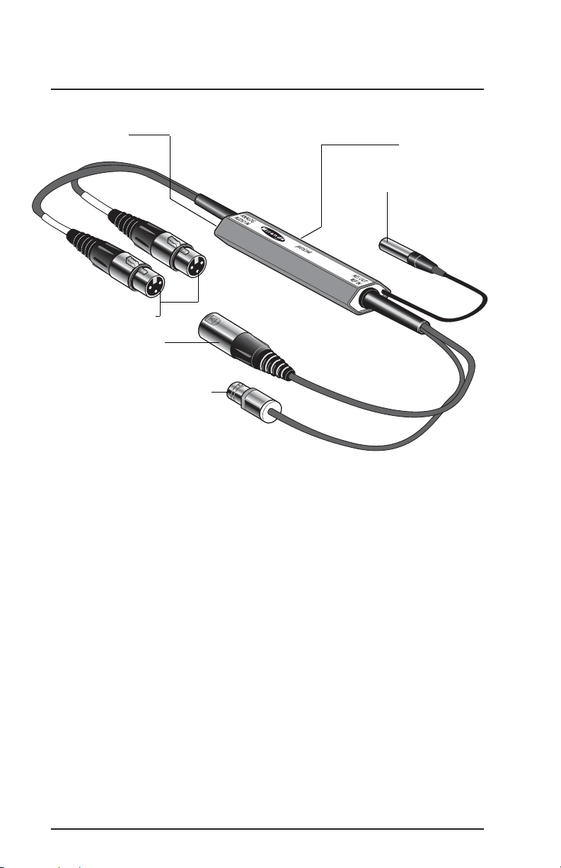
2 Overall view
The figures below represents the ASD-771p/75 and the ASD771p/110. The analog stereo audio source is connected to the
two XLR3 input connectors.
A multicolor LED provides module statuses. A mini slide switch
“Test” configures the test mode. The input level is configurable
using two 3-positions slide switches “Left” and “Right”.
Output is provided by a BNC socket over 75 Ω and a three-point
XLR connector over 110 Ω.
Power supply is connected to a mini-XLR type connector.
Figure 2.1 ASD-771p, 75 Ω Version
Status LED
Input connectors
Output connector
Reference input connector
Slide switches
DC power input connector
3
Page 11
ASD-771p/75/110- Guide to Installation and Operation
LEFT
RIGHT
Figure 2.2 ASD-771p, 110 Ω Version
Status LED
Input connectors
Output connector
Reference input connector
Slide switches
DC power input connector
4
Page 12

ASD-771p/75/110 - Guide to Installation and Operation
3 Installation
3.1 Power Supply
The power supplies LKS-WSA and LKS-WSE, for 110V and 220V
operation respectively, are used to power the ASD-771p/75/110.
Each power supply provides a regulated +5VDC@750mA power
source.
Plug the power supply into a wall or power bar outlet. The ASD771p uses a mini XLR-3 connector for its power needs; figure 3.1
provides a detailed pinout of the male connector.
Figure 3.1 Power connector pinout
13
Shield
GND
+5VDC
2
3.2 Analog Inputs
ASD-771p/75 and ASD-771p/110
Refer to configuration section for the input level adjustment and
test mode configuration.
Analog Audio In
Connect a balanced analog stereo audio signal to the two female
XLR3 connectors labeled LEFT and RIGHT. Refer to figure 3.2
for connector pinout.
5
Page 13

ASD-771p/75/110- Guide to Installation and Operation
Figure 3.2 Input (female) XLR connector pinout
2
High
Low
Ref In
Connect a reference signal PAL, NTSC, AES-3id 75 Ω or Word
clock signal to the BNC plug (female) connector.
Note: The ASD-771p detects automatically a PAL, NTSC, Word
clock (48 kHz) or AES-3id 75
missing, the module delivers an asynchronous AES3 (48 kHz) carrier.
1
3
Ω
signal. When synchronization is
GND
3.3 AES Outputs
ASD-771p/75
Signal is output through a BNC socket (male). Output conforms
to AES-3id-1995 (75 Ω) (SMPTE 276M) or S/PDIF.
ASD-771p/110
Signal is output through a three-point male XLR connector.
Output conforms to AES3-1992 (110 Ω) (ANSI S4.40-1992).
Figure 3.3 shows connector pinout.
Figure 3.3 Male
XLR connector
pinout
1
GND
Low
6
2
3
High
Page 14

ASD-771p/75/110 - Guide to Installation and Operation
4 Operation
4.1 Switch Settings
Figure 4.1 indicates the locations of the miniature switches at the
back of the ASD-771p.
Left Input level adjustment
Right Input level adjustment
Test Mode selection
Figure 4.1 ASD-771p
Switches location
a- Input Level Switches
The adjustment of the stereo analog input level is configurable
with a potentiometer (±1 dB) located on the PCB and with two 3positions slide switches “LEFT” and “RIGHT”. Three levels of
attenuation of the full scale output (0 dBFS) are provided: +20,
+22 or +24 dBU.
b- Test Switch
Two test functions are offered:
Tone
EBU tone generator: sine wave 1 kHz at -18 dBFS interrupted on left channel (250 ms/3 s)
7
Page 15

ASD-771p/75/110- Guide to Installation and Operation
Mute
Absence of audio signal in the AES output carrier (no audio
bit activity).
4.2 Status LED
A multicolored LED, located beside the input, indicates the status
of the module.
Green: The ASD-771p is powered and has detected a
valid audio signal.
Yellow: Test mode is active.
Red: Overload or signal absence on input.
A flashing LED indicates the absence of a valid sync signal.
8
Page 16

ASD-771p/75/110 - Guide to Installation and Operation
5 Specifications
MEASUREMENT CONDITIONS
Inputs: +24 dBu
Outputs: AES FS=48 kHz
ANALOG INPUT
Input impedance: 15 kΩ
Maximum level: +24 dBu
REFERENCE INPUT
Input impedance: 75 Ω
AES3 OUTPUT
AES3
Level Input impedance: 3.4 Vp-p/110 Ω
AES-3id
Level Input impedance: 1.0 Vp-p/75 Ω
SIGNAL PROCESSING
Quantization: 24 bits, 48 kHz
SNR: >105 db (A weighting)
Distortion: < -95 dB @ 1 kHz
Crosstalk: < -100 dBFS @ 15 kHz
Frequency response: ±0.2 dB (20 Hz to 20 kHz)
De-emphasis: ±0.3 dB (digital 50-15 µs)
Tone generator: 1 kHz sine wave (-18 dBFS)
MISCELLANEOUS
9
Page 17

ASD-771p/75/110- Guide to Installation and Operation
10
Page 18

ASD-771p/75/110 - Guide to Installation and Operation
6 Schematic Diagrams
11
 Loading...