

Page 1

DENSITÉ series
AMX-3981
3Gbps/HD/SD 8 AES
Audio & Metadata Embedder
Guide to Installation and Operation
M922-9900-310
16 June 2014
Miranda Technologies
3499 Douglas-B.-Floreani
St-Laurent, Québec, Canada H4S 2C6
Tel. 514-333-1772
Fax. 514-333-9828
www.miranda.com
© 2014 Miranda Technologies
Page 2

GUIDE TO INSTALLATION AND OPERATION
Electromagnetic Compatibility
This equipment has been tested for verification of compliance with FCC Part 15, Subpart B requirements for
Class A digital devices.
NOTE: This equipment has been tested and found to comply with the limits for a Class A digital device, pursuant to
part 15 of the FCC Rules. These limits are designed to provide reasonable protection against harmful interference
when the equipment is operated in a commercial environment. This equipment generates, uses, and can radiate
radio frequency energy and, if not installed and used in accordance with the instruction manual, may cause harmful
interference to radio communications. Operation of this equipmen t in a residenti al area is li kely to cause har mful
interference in which case the user will be required to correct the interference at his own expense.
This equipment has been tested and found to comply with the requirements of the EMC directive
2004/108/CE:
• EN 55022 Class A radiated and conducted emissions
• EN 55024 Immunity of Information Technology Equipment
• EN 61000-3-2 Harmonic current injection
• EN 61000-3-3 Limitation of voltage changes, voltage fluctuations and flicker
• EN 61000-4-2 Electrostatic discharge immunity
• EN 61000-4-3 Radiated electromagnetic field immunity – radio frequencies
• EN 61000-4-4 Electrical fast transient immunity
• EN 61000-4-5 Surge immunity
• EN 61000-4-11 Voltage dips, short interruptions and volta ge var iat ions immunity
Manufactured under licens e from Dolby Labor at ories . Dolby and the Double-D symbol are trademarks of Dolby
Laboratories.
How to contact us:
For technical assistance, please contact the Miranda Technical support center nearest you:
Americas
9:00 am – 9:00 pm EST
Tel: +1 800 224 7882
Fax: +1 514 335 1614
support@miranda.com
France
9:00 am – 5:00 pm GMT+1
Tel: +33 1 55 86 87 88
Fax: +33 1 55 86 00 29
eurotech@miranda.com
Asia
9:30 am – 6:00 pm GMT+8
Tel: +852 2539 6987
Fax: +852 2539 0804
asiatech@miranda.com
China
9:30 am – 6:00 pm GMT+8
Tel: +86 10 5873 1814
asiatech@miranda.com
Europe, UK, Middle East, Africa
9:00 am – 6:00 pm GMT
Tel: +44 118 952 3444
Fax: +44 118 952 3401
eurotech@miranda.com
(Playout Automation Only)
9:00 am – 5:30 pm GMT
Tel: +44 8705 004 350
Fax: +44 8705 004 333
automationsupport@miranda.com
Emergency After Hour s
Tel: 1 800 224 7882
-orTel: 1 514 333 1772
and choose menu
option 2
(worldwide)
Visit our web site at www.miranda.com
AMX-3981
Page 3

GUIDE TO INSTALLATION AND OPERATION
Table of Contents
1 AMX-3981 3Gbps/HD/SD 8 AES Audio & Metadata Embedder .............................................. 1
1.1 Introduction ......................................................................................................................................... 1
1.2 Features .............................................................................................................................................. 2
1.3 Functional Block Diagram ................................................................................................................... 3
1.4 Front Card-edge Interface ................................................................................................................... 3
2 Installation ................................................................................................................................ 4
2.1 Installation of Rear Connector Panels ................................................................................................ 4
2.2 AMX-3981 Card Installation ................................................................................................................ 5
2.3 Installation of the Optical Interface (option) ........................................................................................ 5
2.4 Rear Panels and Connectors .............................................................................................................. 5
2.4.1 Images of Rear Panel Connectors ......................................................................................... 5
2.4.2 Summary of rear panel connections ...................................................................................... 6
2.4.3 Details of rear panel connections .......................................................................................... 6
3 User Interface ......................................................................................................................... 10
3.1 Control options .................................................................................................................................. 10
3.2 Card-Edge Status LED ..................................................................................................................... 10
4 Local control using the Densité frame control panel .......................................................... 11
4.1 Overview ........................................................................................................................................... 11
4.2 Menu for local control ........................................................................................................................ 11
5 Remote control using iControl .............................................................................................. 12
5.1 The iControl graphic interface window .............................................................................................. 12
5.2 Video Input/Output panel .................................................................................................................. 15
5.2.1 Fiber Input/Output tab .......................................................................................................... 15
5.2.2 Deglitcher tab ....................................................................................................................... 15
5.2.3 Freeze tab ............................................................................................................................ 18
5.2.4 Timing tab ............................................................................................................................ 18
5.2.5 SFP Info tab ......................................................................................................................... 20
5.3 Metadata panel ................................................................................................................................. 20
5.3.1 LTC tab ................................................................................................................................ 20
5.3.2 GPI tab ................................................................................................................................. 21
5.3.3 AFD tab ................................................................................................................................ 22
5.4 Audio Processing panel .................................................................................................................... 24
5.4.1 Audio Proc – Levels tab ....................................................................................................... 26
5.4.2 Audio Proc – Fixed Delay tab .............................................................................................. 26
5.4.3 Audio Proc – Silence tab ...................................................................................................... 27
5.4.4 Downmix .............................................................................................................................. 27
5.4.5 AES Inputs tab ..................................................................................................................... 30
5.4.6 Status tab ............................................................................................................................. 30
5.5 Miranda ALC panel ........................................................................................................................... 31
5.5.1 Config tab ............................................................................................................................. 31
5.5.2 PGM1-8 tabs ........................................................................................................................ 32
5.6 Dynamic Processing panel ............................................................................................................... 34
5.7 Audio Modules panel ........................................................................................................................ 37
AMX-3981
Page 4

GUIDE TO INSTALLATION AND OPERATION
Dolby Metadata panel ........................................................................................................................ 37
5.8
5.8.1 Config tab ............................................................................................................................. 37
5.8.2 Input/Output tab .................................................................................................................... 45
5.9 Audio Output panel ............................................................................................................................ 46
5.9.1 CH 1-2, CH 3-4, … CH 15-16 tabs ....................................................................................... 46
5.9.2 Config tab ............................................................................................................................. 47
5.10 Loudness Panel ................................................................................................................................. 48
5.10.1 Loudness | Config panel ....................................................................................................... 48
5.10.2 Loudness | PGM panel ......................................................................................................... 49
5.10.3 Loudness | Logging Panel .................................................................................................... 51
5.11 Fingerprint panel ................................................................................................................................ 52
5.12 Reference panel ................................................................................................................................ 53
5.13 Monitoring panel ................................................................................................................................ 53
5.13.1 Thumbnails tab ..................................................................................................................... 53
5.13.2 RALM tab .............................................................................................................................. 54
5.14 Test panel .......................................................................................................................................... 55
5.15 Factory/Presets panel ........................................................................................................................ 56
5.15.1 Factory/Presets tab .............................................................................................................. 56
5.15.2 Automatic Preset Recall tab ................................................................................................. 60
5.16 Options panel .................................................................................................................................... 64
5.16.1 Dynamic Processing option: ................................................................................................. 64
5.16.2 ALC option ............................................................................................................................ 65
5.16.3 Loudness Measurement option ............................................................................................ 65
5.17 Alarm Config panel ............................................................................................................................ 66
5.18 Info panel ........................................................................................................................................... 69
6 Audio Modules ....................................................................................................................... 71
6.1 Dolby E and Dolby Digital decoder ................................................................................................... 71
6.1.1 Control tab ............................................................................................................................ 71
6.1.2 Dolby E tab ........................................................................................................................... 72
6.1.3 Dolby Digital tab ................................................................................................................... 73
6.1.4 PCM tab ................................................................................................................................ 73
6.2 Dolby Digital and Dolby Digital Plus encoder .................................................................................... 74
6.2.1 Shuffler Inputs ...................................................................................................................... 74
6.2.2 Configuration ........................................................................................................................ 74
6.2.3 Status:................................................................................................................................... 75
6.3 Dolby E encoder ................................................................................................................................ 76
6.3.1 Input and Output channel selection ...................................................................................... 76
6.3.2 Configuration ........................................................................................................................ 76
6.3.3 Status:................................................................................................................................... 77
6.4 Upmixing using Linear Acoustic Technology upMAXTM .................................................................... 78
6.5 N-channel ALC and upmix licensed by Linear Acoustic .................................................................... 80
6.5.1 Config tab ............................................................................................................................. 81
6.5.2 Basic tab ............................................................................................................................... 82
6.5.3 Advanced Configuration – ALC PGM 1 & 2 ......................................................................... 83
6.5.4 Upmix using Linear Acoustic UpMAXtm ................................................................................ 88
6.6 N-channel ALC licensed by Jünger Audio & upmix by Linear Acoustic ............................................ 89
6.6.1 ALC Models .......................................................................................................................... 89
AMX-3981
Page 5

GUIDE TO INSTALLATION AND OPERATION
Program Configurations ....................................................................................................... 89
6.6.2
6.6.3 Loudness Monitoring ............................................................................................................ 94
6.6.4 ALC PGMx Configuration ..................................................................................................... 95
6.6.5 Notes .................................................................................................................................... 98
7 Specifications......................................................................................................................... 99
ANNEX 1 – AMX-3981 Local User Interface ............................................................................. 101
ANNEX 2 – Installing the Optical Interface ............................................................................... 103
ANNEX 3 – Installing the Audio Modules ................................................................................. 105
ANNEX 4 – Dolby Digital Main Channel Output Functions ..................................................... 108
ANNEX 5 – AFD Flags ................................................................................................................ 109
ANNEX 6 - Loudness Logging and the Miranda Audio Loudness Analyzer ......................... 111
AMX-3981
Page 6

GUIDE TO INSTALLATION AND OPERATION
AMX-3981
Page 7

GUIDE TO INSTALLATION AND OPERATION
1 AMX-3981 3Gbps/HD/SD 8 AES Audio & Metadata Embedder
1.1 Introduction
The AMX-3981 is an advanced, high quality audio processor which embeds up to eight (8) AES signals into a
3Gbps/HD/SD video signal. Each AES input can accept different sample rates, or even asynchronous audio, and will
be resampled at 48 kHz by a sample rate converter, which can be manually or automatically disabled in the presence
of non-PCM audio.
The AMX-3981 can simultaneously process up to 32 channels of audio (16 channels from the discrete AES inputs,
and 16 channels of embedded audio). Functions include down-mixing, Proc Amp, channel shuffling and mixing.
Options include Automatic Loudness Control, dynamic processing (limiter, compressor, and expander) and loudness
measurement. The AMX-3981 generates audio/video fingerprints (via an iControl option) to detect and measure lipsync errors in a broadcast facility.
The new loudness measurem ent option allows t he m easurem ent and log ging of up to 4 audio program s with i Control
Loudness Monitoring sof tware to analyze and report com pliance with respect to v arious loudness legis lations around
the world (See iControl Loudness Monitoring).
The AMX-3981 has one on-board socket for optional modules, including Dolby E and Dolby Digital decoding,
upmixing using Linear Acoustic upMAX™ technology, Dolby E encoding, Dolby Digital and Dolby Digital Plus
encoding. In addition to Mir anda’s own autom atic loudnes s control (ALC) s olution for up to eight pr ogram s, the AMX3981 offers ALC using the AEROMAX™ technology by Linear Acoustic, or Level Magic™ by Jünger Audio,
implemented using optional modules.
The card will pass and delay automatical ly all 32 internal aud io channels to pres erve lip-s ync between the channe ls.
Each channel can be delayed independently to correct any lip-sync issues. All audio channels can be mixed and
shuffled to provide 16 channels for embedding in the video output.
An Automatic Preset Recall feature provides basic automation to select user preset based on the status of the
incoming audio.
When genlocked to the fram e reference using the inter nal URS signal, the AMX -3981 can handle video hot switches
at the input without losing sync at the output. In the absence of a video input, the card can still output synchronous
video and embed the discrete AES audio.
The card has a fram e buffer (not a frame sync) which allows an increas e in the video delay of up to 15 fram es to
compensate for the long a udio processing delay required b y some modules. F or applications which require a sm all
processing delay, the frame buffer can be bypassed to reduce the delay to a few micro-seconds.
The AMX-3981 can embed Linear Time Code (LTC) as ancillary Time Code (ATC) in 3Gbps/HD and DVITC in SD. Up
to 3 GPIO can be used as input, or output, to embed or extract GPI events to/from the Time Code user bits in
transport applications. They can also be used simultaneously to trigger the card’s user presets.
Dolby Metadata insertion in the VANC is possible from multiple sources, such as a Dolby E decoder module, an
embedded VANC stream , an external RS-422 link , or from the integrated Metadata ge nerator. All parameter s in the
Metadata stream can be probed and monitored. Dolby Metadata can be used to steer the behavior of the audio
downmix and upmix modules.
A fiber input/output c artridg e is offer ed as an opt ion on som e rear m odules. Once the cartri dge is ins talled, th e inputs
or outputs are selec table through the control interface. The input of the card allows you to select between f iber and
copper inputs. The outputs are via copper and fiber simultaneously (with appropriate fiber cartridge).
AMX-3981 | 1
Page 8

GUIDE TO INSTALLATION AND OPERATION
1.2 Features
Video
• 3Gbps/HD/SD input
• Supports 3Gbps level A (mapping 1) and level B
• Audio/Video deglitcher to handle video hot switch at the input
• Automatic detection of input video loss and switchover to local grey for continuity of embedded audio
• Flexible HD/SD reference using the internal URS frame reference
• Minimum processing delay of 7.5 μs (HD), but additional delay can be added up to 15 frames
• Optional optical fiber module
• Compatible with iControl end-to-end A/V fingerprint analyzer for lip sync error detection and measurement
Audio
• 8 AES inputs
• Sample rate conversion for asynchronous AES inputs
• Full audio shuffling and mixing on a channel basis
• 32 channels internal audio processing
• Audio 5.1 surround down-mix to Lt/Rt or Lo/Ro
• Audio dynamic processor option (compressor/limiter/expander)
• Optional on-board Automatic Loudness Control with Miranda Wideband processing
• Optional loudness measurement of up to 4 audio program s and loggin g with iCon t r ol
o Loudness compliant to EBU R128, ATSC A/85 and ARIB TR-B32 (ITU-R BS.1770-3)
• Audio delay adjustments of up to 2 seconds to compensate for lip-sync issues
• A/V fingerprint generati on (an iControl option) for lip-sync measurement
• On-board socket for 1 optional expansion module:
o Dolby E and Dolby Digital decoder module
o Dolb y E encoder module
o Dolby Digital and Dolby Digital Plus encoder module
o Linear Acoustic upMAX ™ audi o stereo to 5.1 upmixing
o Linear Acoustic AEROMAX™ Automatic Loudness Control
o Jünger Audio LevelMagic™ Automatic Loudness Control
Metadata
• AFD (SMPTE-2016), VLI (RP-186) and WSS insertion
• Linear Time Code (LTC) embedding into DVITC (SD) or ATC (HD)
• Dolby Metadata insertion and extraction (SMPTE 2020)
• RS-422 serial data input & output to carry audio metadata
• GPI inputs & outputs that can be inserted or extracted from the embedded timecode user bits. They can also be
used for
automation, user preset recall and loudness reset.
2 | AMX-3981
Page 9
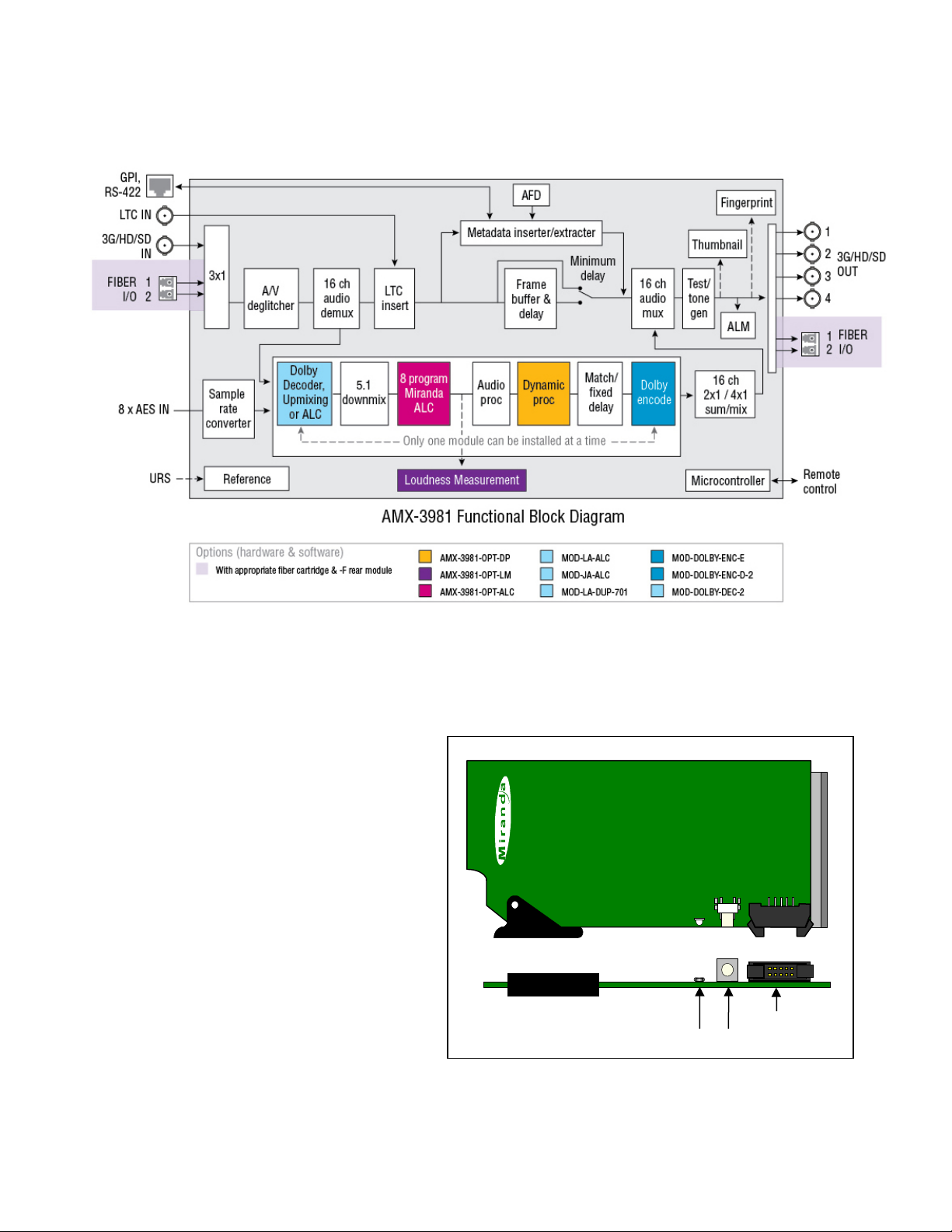
1.3 Functional Block Diagram
SDA-1101 - SD DIGITAL VIDEO DISTRIBUTION AMPLIFIER
Select
Status
SELECT button
(Future use)
AMX-3981
Status LED
GUIDE TO INSTALLATION AND OPERATION
Figure 1.1 AMX-3981 Functional Block Diagram
1.4 Front Card-edge Interface
The front card-edge of the AMX-3981 incorporates
two elements:
• Status LED (see section 3.2)
• Select Button (see section 4)
Figure 1.2 Front card-edge layout
AMX-3981 | 3
Page 10
GUIDE TO INSTALLATION AND OPERATION
2 Installation
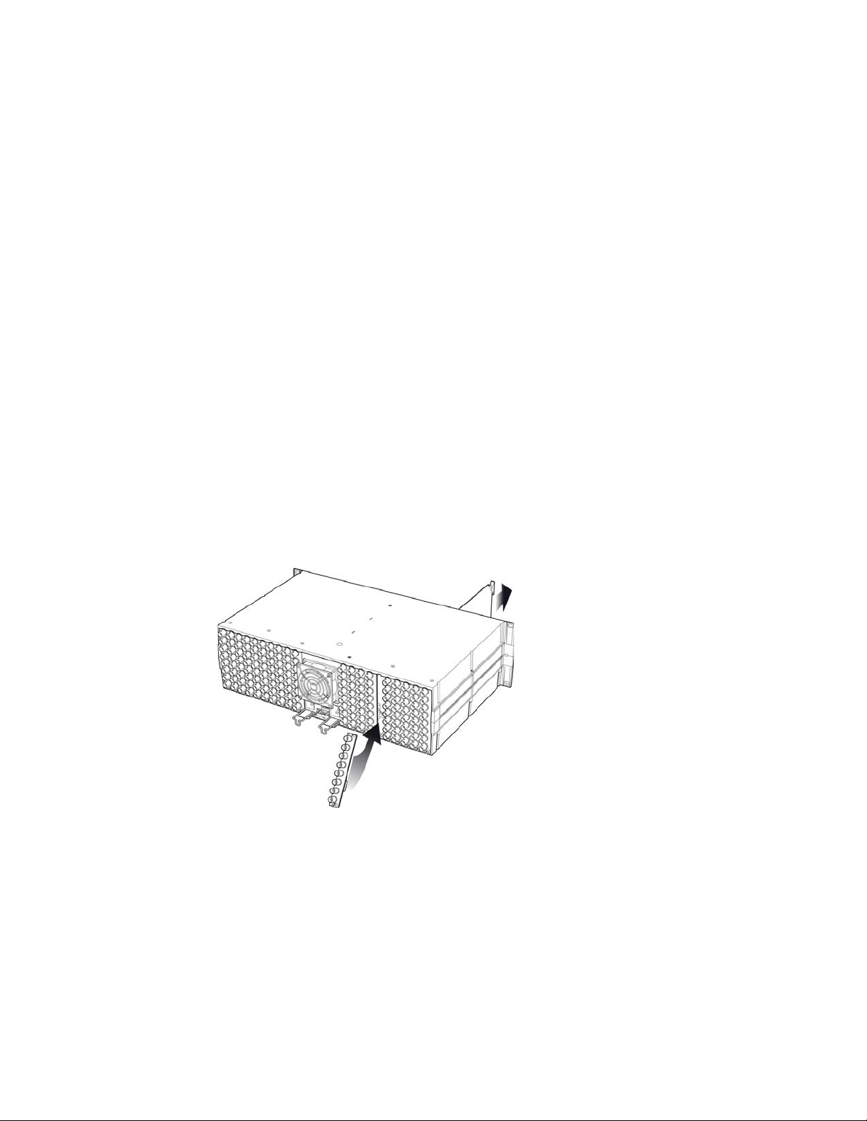
2.1 Installation of Rear Connector Panels
Miranda Densité-series cards are each associated with a rear connector panel, which must be installed in the Densité
frame before the card can be inserted.
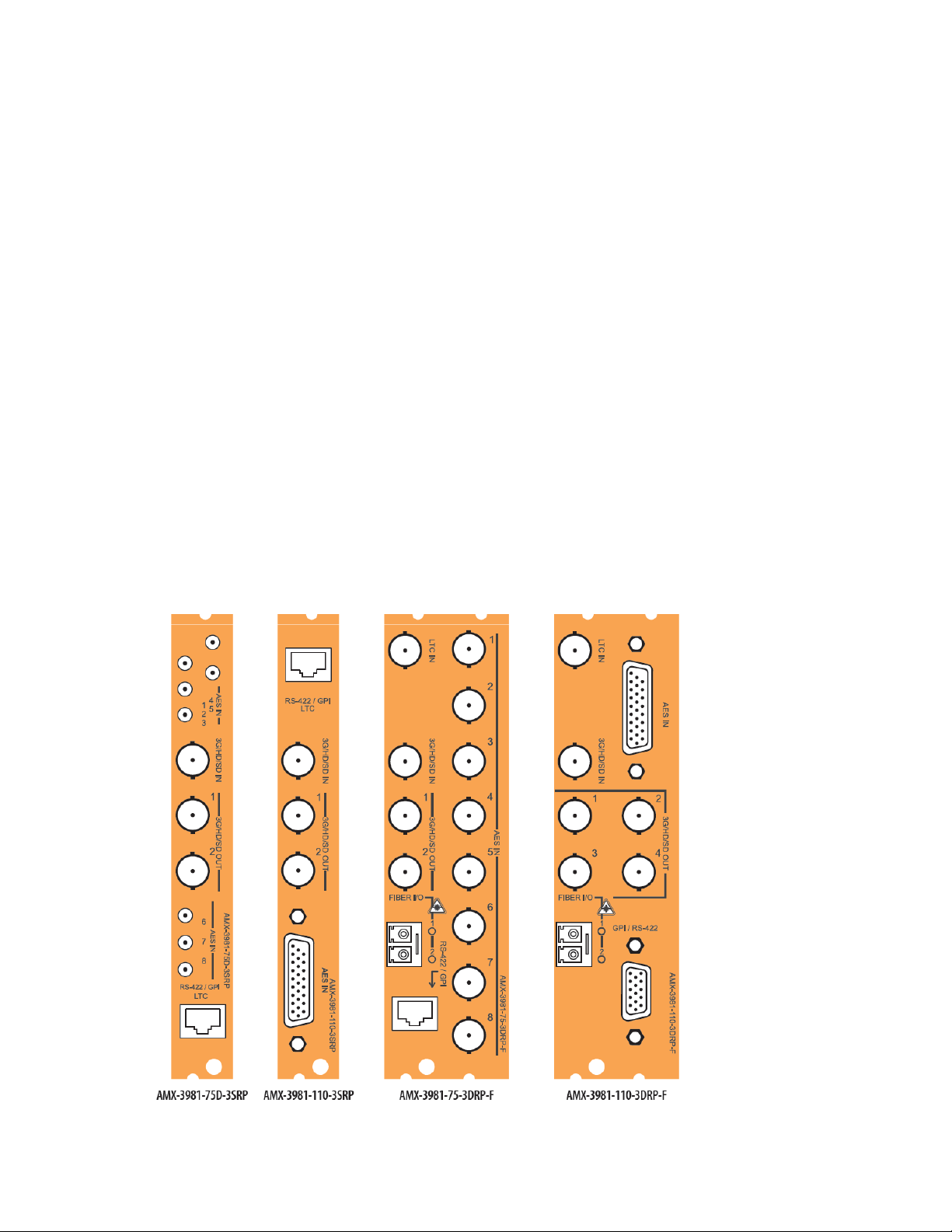
The AMX-3981 card is designed to fit into Miranda’s Densité-3 frame. Four different rear connector panels are
available:
• AMX-3981-75D-3SRP Single-slot-width panel with 75Ω audio
• AMX-3981-110-3SRP Single-slot-width panel with 75Ω audio
• AMX-3981-75-3DRP-F Double-slot-width panel with 75Ω audio and fiber I/O
• AMX-3981-110-3DRP-F Double-slot-width panel with 110Ω audio and fiber I/O
See section 2.4 for details of the signal connections available on each of these panel types.
All cards and rear panels can be installed with the frame power on. The card has connectors which plug into a mid-
frame mother board for distribution of power and for connection to the controller card, and a second connector which
plugs directly into the rear connector panel for input and output.
The rear connector panel must be installed with the card out of the frame.
• To remove an existing card from the slot, tilt up the swivel handle on the front of the card to lever the connectors
apart, then use the handle to pull the card straight out of the slot.
Figure 2.1 Densité-3 frame – rear panel installation
To install the connector panel:
1. If a card is installed in the slot whose rear panel is being changed, remove it as described above.
2. Remove the existing panel (either blank or belonging to an existing card that is being changed) by releasing the
captive screw(s) at the bottom.
3. Position the new panel and secure it in place with the captive screw(s) at the bottom.
4 | AMX-3981
Page 11
GUIDE TO INSTALLATION AND OPERATION
2.2 AMX-3981 Card Installation
Once a matching rear connector panel has been installed, install the AMX-3981 card as follows:
1. Open the front panel of the frame.
2. Slide the AMX-3981 card into the slot and push gently on the handle to seat the connectors.
When using a double-slot-width rear panel, the card should be inserted into the right-most of the two slots.
Inserting the card into the wrong slot will not damage the card, and will be flagged by the on-card status LED
flashing red to indicate that there is no connection to the rear panel.
3. Close the front panel of the frame.
2.3 Installation of the Optical Interface (option)
Refer to Annex 3 on page 103.
2.4 Rear Panels and Connectors
2.4.1 Images of Rear Panel Connectors
The four available rear panels are shown in the figure below, and their various inputs and outputs are described.
AMX-3981 | 5
Page 12

GUIDE TO INSTALLATION AND OPERATION
♦ ♦
♦ ♦
3
3
♦ ♦
2
2
♦ ♦
2.4.2 Summary of rear panel connections
AMX-3981-75D-3SRP
AMX-3981-110-3SRP
AMX-3981-75-3DRP-F
AMX-3981-110-3DRP-F
Single-slot-width panel
Double-slot-width panel
CONNECTORS
3G/HD/SD IN
3G/HD/SD OUT
AES IN (110Ω) on D-SUB
AES IN (75Ω) on BNC
GPI (#) & RS-422 on D-SUB
GPI (#) and RS-422 A on RJ45
1
4
8
1 1 1
2 2 2
8
8 8
LTC IN on BNC
GPI (#), LTC IN and RS-422 A on RJ45
Fiber I/O module
2.4.3 Details of rear panel connections
3G/HD/SD SDI IN – Serial digital 3G/HD/SD input
Connect a serial digital video signal, conforming to the SMPTE 425M standard for 3G input signals, SMPTE 292M
standard for HD input signals or SMPTE 259M standard for SD input signals, to the BNC labeled 3G/HD/SD SDI IN.
The AMX-3981 will automatically switch to the detected line/frame rate format.
• Note: if you are using the Densité frame’s URS signal as the reference, then you must make sure that the input
SDI is locked to the URS.
3G/HD/SD SDI OUT – Serial digital video outputs
The AMX-3981 provides two or four (depending upon the rear panel in use) 3G/HD/SD SDI video outputs on BNC
connectors, labeled 3G/HD/SD OUT 1, 2, 3 and 4. The SDI video signal conforms to the SMPTE 425M, SMPTE
292M or SMPTE 259M-C standard. The same signal is carried on all outputs.
AES IN – Discrete AES3 digital audio inputs (8)
The AES inputs can be configured for 110 ohm impedance using a 26-pin D-SU B connec tor , or 75 ohm impedance
using BNC or DIN 1.0/2.3 connectors. Rear connector panels are available for each option.
6 | AMX-3981
Page 13
GUIDE TO INSTALLATION AND OPERATION
Rear Panel Type Connector(s) / Impedance
AMX-3981-110-3DRP-F
AMX-3981-110-3SRP
AMX-3981-75-3DRP-F
AMX-3981-75D-3SRP
D-SUB 26 (1) 110Ω
D-SUB 26 (1) 110Ω
BNC (8) 75 Ω
DIN 1.0/2.3 (8) 75 Ω
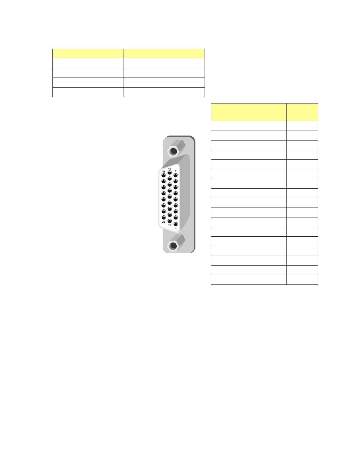
The pinout of the D-SUB connector for both 110Ω rear panels is
shown in this chart.
AMX-3981-110-3SRP
AMX-3981-110-3DRP-F
AES IN 1 (Hi)
AES IN 1 (Lo)
AES IN 2 (Hi)
AES IN 2 (Lo)
AES IN 3 (Hi)
AES IN 3 (Lo)
AES IN 4 (Hi)
AES IN 4 (Lo)
AES IN 5 (Hi)
AES IN 5 (Lo)
AES IN 6 (Hi)
AES IN 6 (Lo)
AES IN 7 (Hi)
AES IN 7 (Lo)
AES IN 8 (Hi)
AES IN 8 (Lo)
GND
Pin #
1
10
2
11
3
12
4
13
5
14
6
15
7
16
8
17
9, 18-26
Fiber I/O – Fiber-optic inputs and outputs
Rear panels whose part number ends in –F incorporate a fiber optic interface. The interface consists of two parts:
• A socket on the rear panel into which an SFP interface module is plugged
• An SFP (Small Form-factor Pluggable) module into which the optical fibers are plugged, and which incorporates
the optical/electrical interface
The optical fibers must be terminated in an LC connector.
See Annex 3 for instructions on installing and removing the SFP interface module, and for plugging and unplugging
the LC-terminated fibers.
The SFP modules supported by the AMX-3981 are:
AMX-3981 | 7
Page 14
GUIDE TO INSTALLATION AND OPERATION
Function
Pin #
GPIO USER1
7
GPIO USER2
5
GPIO USER3
4
RS422-RX1-1
1
RS422-RX1-0
2
RS422-TX2-1
3
RS422-TX2-0
6
GND
8
SFP Modules Description
SFP-RR-LC Dual Rx module with LC connector
SFP-TT-S13S13-LC Dual Tx module at 1310 nm with LC connector
SFP-RT-S13-LC Single Rx and Tx transceiver module at 1310 nm with LC connector
SFP-R-LC Single Rx module with LC connector
SFP-T-S13-LC Single Tx module at 1310 nm with LC connector
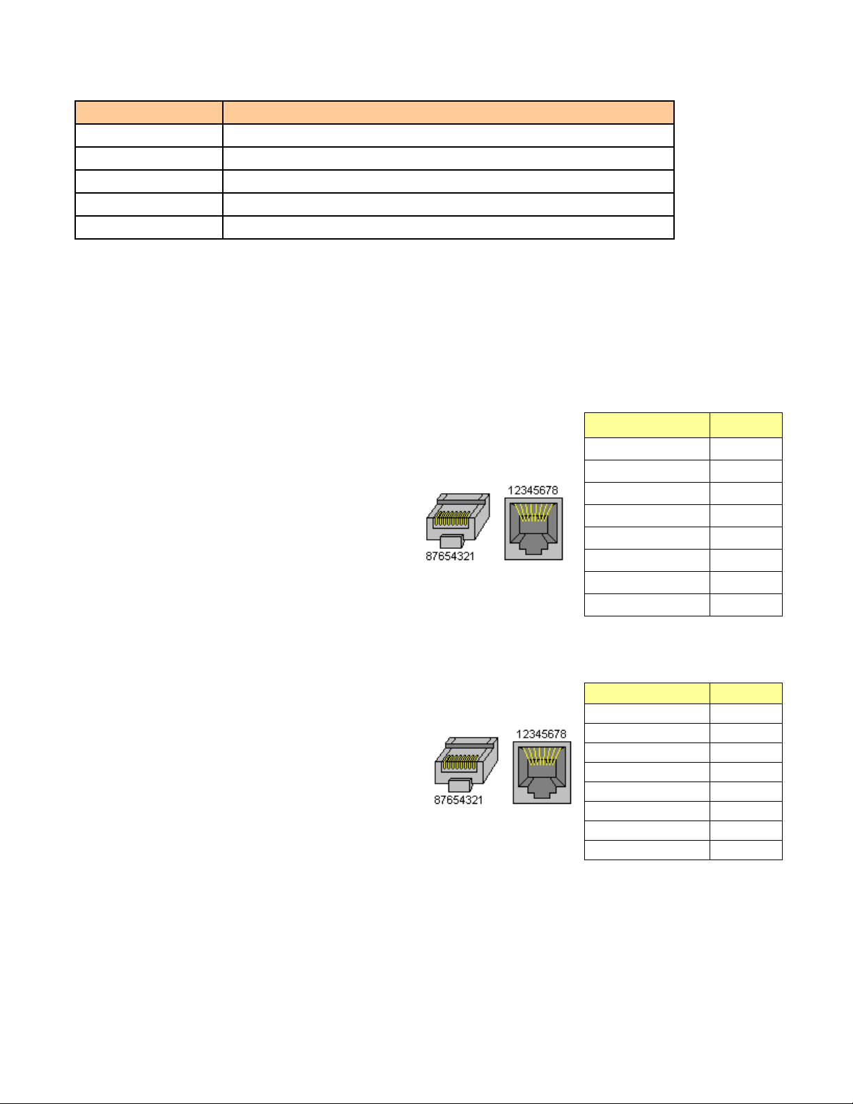
GPI / RS-422 B / LTC – GPI I/O and Metadata I/O
GPI, RS-422 and LTC signals are carried on different connector types on the various rear panels available for the
AMX-3981, to make most effective use of the available panel area.
AMX-3981-75D-3SRP and AMX-3981-110-3SRP
For the two single width rears, all three signals are carried on an RJ-45
connector, with the pinout as shown in the table:
Note that in this configuration, only two GPIO are available, while the doublewidth rear panels carry three
Function
GPIO USER1
GPIO USER2
LTC
RS422-RX1-1
RS422-RX1-0
RS422-TX2-1
RS422-TX2-0
GND
Pin #
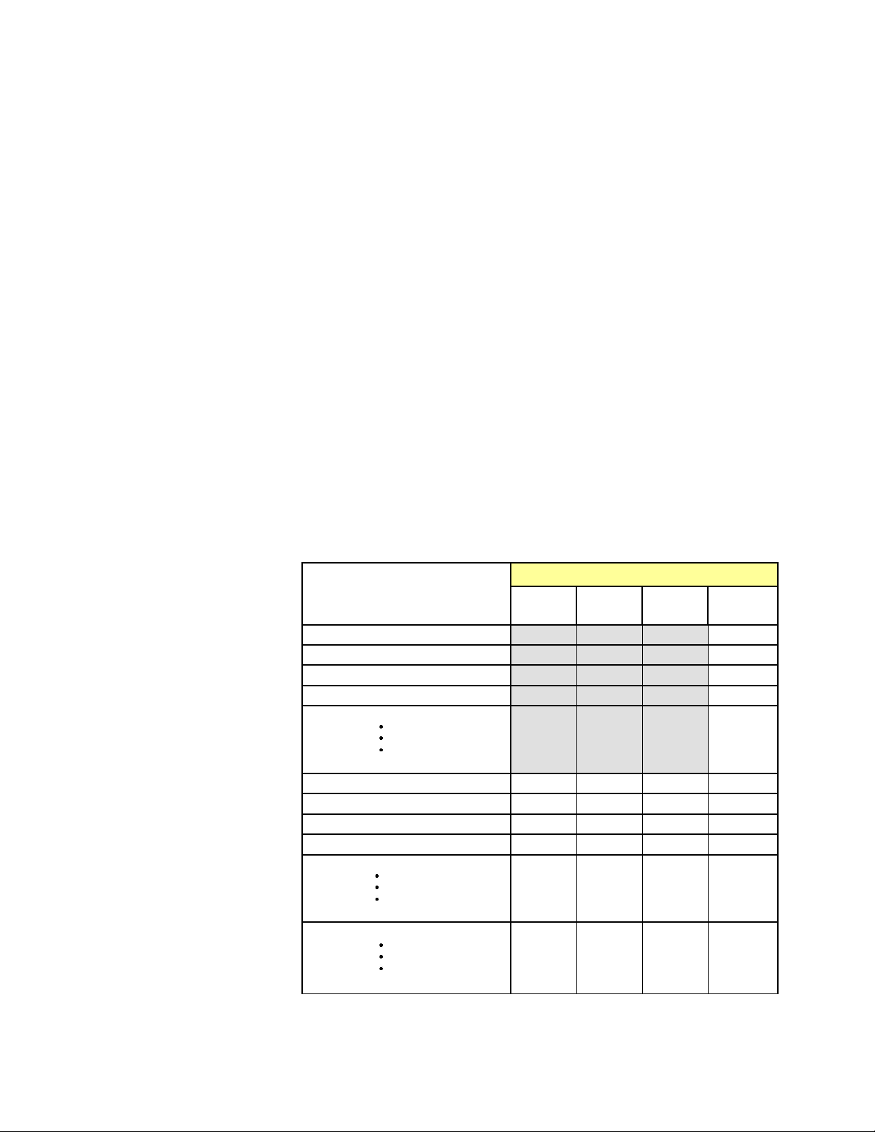
AMX-3981-75-3DRP-F
This rear panel carries three GPIO and RS-422 on an RJ45 connector and
LTC on a separate BNC connector. The pinout of the RJ45 is as follows:
7
5
4
1
2
3
6
8
8 | AMX-3981
Page 15

AMX-3981-110-3DRP-F
This rear panel carries three GPIO and RS-422 on a 15-pin D-SUB connector
and LTC on a separate BNC connector. The pinout of the 15-pin D-SUB is as
follows:
GUIDE TO INSTALLATION AND OPERATION
Function
GPIO USER1
GPIO USER2
GPIO USER3
RS422-RX1-1
RS422-RX1-0
RS422-TX2-1
RS422-TX2-0
GND
NC
Pin #
3
8
10
1
6
2
7
5,11,12,
14,15
4, 9, 13
AMX-3981 | 9
Page 16
GUIDE TO INSTALLATION AND OPERATION
The LED will always show the most
Error Condition
LED Status
Green
Yellow
Red
Flashing
Red
3 User Interface
3.1 Control options
The AMX-3981 can be cont r olled in three different ways:
• The local control panel and its push-buttons can be used to move through a menu of parameters and to adjust
parameter values (see section 4).
• Miranda’s iControl system can be used to access the card’s operating parameters from a remote computer, using
a convenient graphical user interface (GUI) (see section 5).
• Miranda’s RCP-200 panel (check for availability).
3.2 Card-Edge Status LED
The status monitor LED is located on the front card-edge of the AMX-3981, and is visible through the front access
door of the DENSITÉ frame. This multi-color LED indicates the status of the AMX-3981 by color, and by
flashing/steady illum ination.
The chart shows how the various error conditions that can be flagged on the AMX-3981 affect the LED status.
• If a cell is gray, the error condition cannot cause the LED to assume that status
• If more than one LED status is possible for a particular error condition, the status is configurable.
See Sec t ion 5.16 for details.
• The factory default status is shown by a
severe detected error status that it is
configured to display, and in the chart
error severity increases from left to
right, with green representing no
error/disabled, and flashing red the
most severe error.
If the LED is Flashing Yellow, it
means that the card is selected for
local control using the Densité frame’s
control panel. See Section 4 for
details.
Cooling Fan 1 error
FPGA error
Dataflash Error
No Rear
AES Receiver 1 error
AES receiver 8 error
Reference missing
Reference mismatch
Test Mode
Carrier 1 detect error
AES 1 Presence error
AES 8 Presence error
Silence detected Channel 1
Silence detected Channel 32
10 | AMX-3981
Page 17
GUIDE TO INSTALLATION AND OPERATION
Figure
4 Local control using the Densit é fra me control panel
4.1 Overview
Push the SELECT button on the AMX-3981 card edge
(see Section 1.4) to assign the local control panel to
operate the AMX-3981. Use the control panel buttons
to navigate through the menu, as described below.
All of the cards installed in a Densité frame are
connected to the frame’s controller card, which handles
all interaction between the cards and the outside wor ld .
There are no operating controls located on the cards
themselves. The controller supports remote operation
via its Ethernet ports, and local operation using its
integrated control panel.
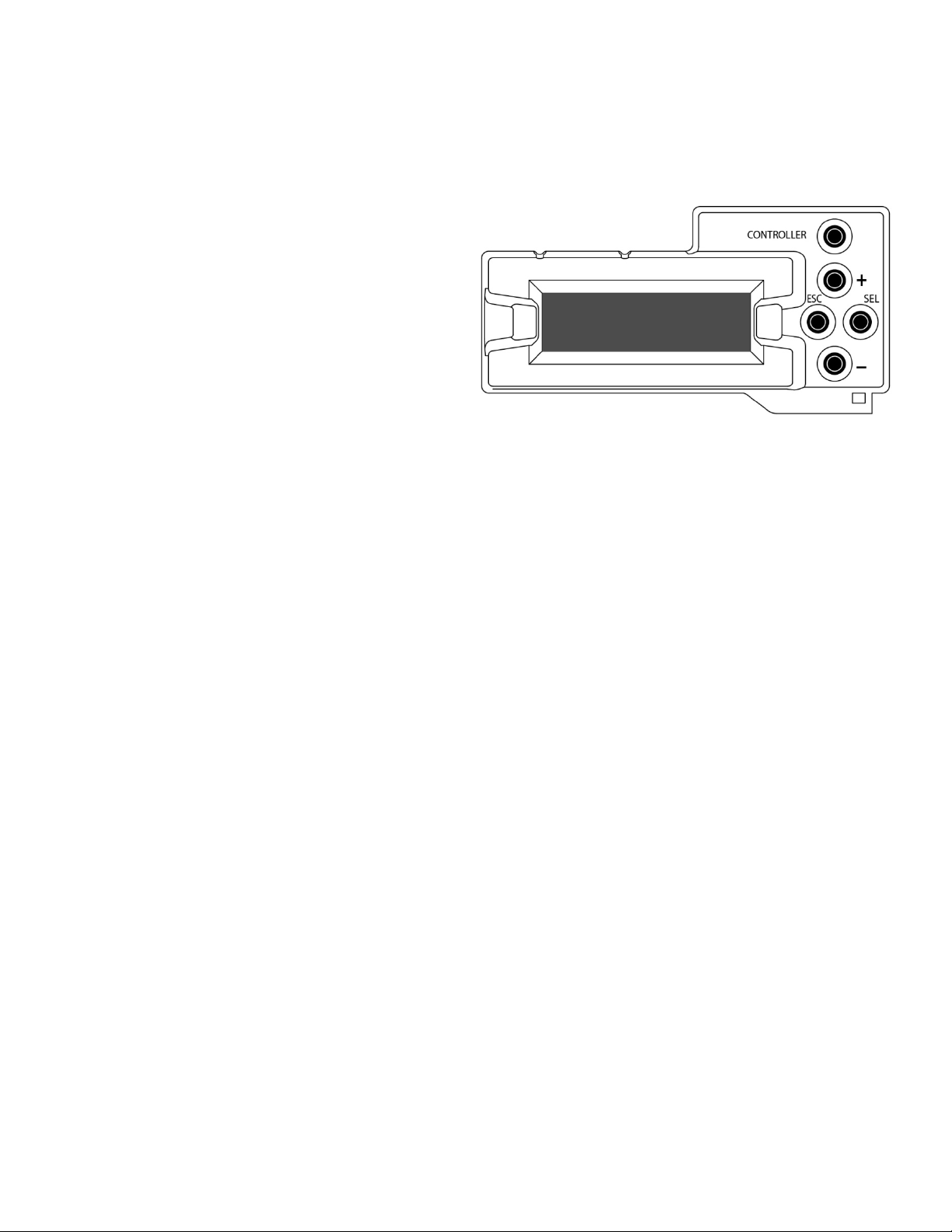
The local control panel is fastened to the front of the
CPU-ETH2 control ler car d, and when installed is located in the front center of the frame, positioned in front of the
power supplies. The panel consists of a display unit capable of displaying two lines of text, each 16 characters in
length, and five pushbuttons .
The panel is assigned to operate any card in the frame by pushing the SELECT button on the front edge of that card.
• Pushing the CONTROLLER button on the control panel selects the Controller card itself.
• The STATUS LED on the selected card flashes yellow.
The local control panel displays a menu that can be navigated using the four pushbuttons located beside the displ a y.
The functionality of the pushbuttons is as follows:
[+] [–] Used for menu navigation and value modification
[SELECT] Gives access to the next menu level. When a parameter value is shown, pushing this button once
enables modification of the value using the [+] and [–] buttons; a second push confirms the new value
[ESC] Cancels the effect of parameter value changes that have not been confirmed; pushing [ESC] causes the
parameter to revert to its former value.
Pushing [ESC] moves the user back up to the previous menu level. At the main menu, [ESC] does not
exit the menu system. To exit, re-push the [SELECT] button for the card being controlled.
If no controls are operated for 30 seconds, the controller reverts to its normal standby status, and the selected card’s
STATUS LED reverts to its normal operating mode.
4.2 Menu for local control
The AMX-3981 has operating parameters which may be adjusted locally at the controller card interface.
• Press the SELECT button on the AMX-3981 front card edge to assign the Densité frame’s local control panel
to the AMX-3981
• Use the keys on the local control panel to step through the displayed menu to configure and adjust the AMX-
3981.
The complete menu structure is shown in Annex 1 to this document, beginning on page 100.
4.1 Densité Frame local control panel
AMX-3981 | 11
Page 18
GUIDE TO INSTALLATION AND OPERATION
2
Figure
5 Remot e c ont rol using iControl
The operation of the AMX-3981 may be controlled using Miranda’s iControl system.
• This manual describes the control panels associ ated with the AMX-3981 and their use.
• Please consult the iControl User’s Guide for information about setting up and operating iControl.
In iControl Navigator or iControl Websites, double-click on the AMX-3981 icon to open the control panel.
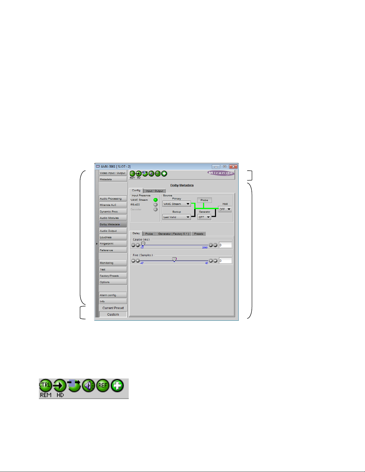
5.1 The iControl graphic interface window
The basic window structure for the AMX-3981 is shown in figure 5.1. The window identificat ion li ne gives the c ard type
(AMX-3981) and the slot number where the card is installed in its Densité frame.
There are four main sections in the window itself, identified in figure 5.1:
Section 1. The top section displays six icons on the left. These icons report different statuses such as card
communication status, input signal and reference signal format and statuses. In some instances, they relate to
conditions defined through parameters settings.
Icon # 1 2 3 4 5 6
Move the mouse over an icon and a status message appears below the icon providing additional information.
5.1 AMX-3981 iControl graphic interface window
12 | AMX-3981
Page 19
GUIDE TO INSTALLATION AND OPERATION
If there is an error, the error status message appears in the message area w ithout mouse-over.
• If there are multiple errors, the error messages cycle so all can be seen
• The icon whose status or error message is shown is highlighted with a mauve background
The table below describes the various status icons that can appear, and how they are to be interpreted.
• In cases where there is more than one possible interpretation, read the error message in the iControl window to
see which applies.
Table –iControl Status Icon interpretation
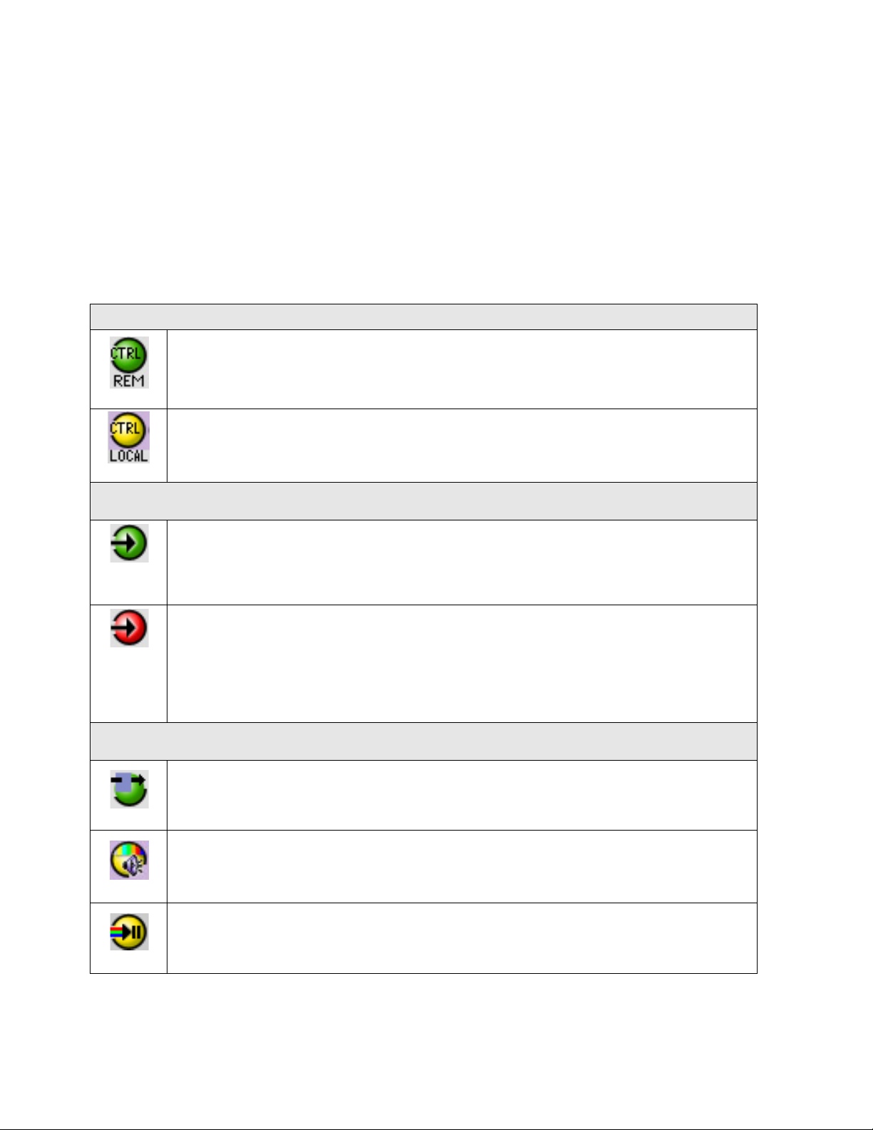
Icon #1 – Manual Card Configuration
Remote card control activated. The iControl interface can be used to operate the card
(green)
Local card control active, The card is being controlled using the Densité frame control
panel, as described in section 4. Any changes made using the iControl interface will have
(yellow)
no effect on the card.
Icon #2 – Input status
Signal detected and valid.
(green)
• Beneath the icon, the format will be indicated as 3G, HD or SD, and the specific
format details will be listed if the cursor is moved over the icon.
Signal absent
(red)
No rear
Reference mismatch
Video/TRS error
Icon #3 – Operation Mode
Operation mode: process – normal processing of the input signal
(green)
Operation mode: TEST – color bar and audio test tones enabled (see Sect. 5.13)
(yellow)
(yellow)
Operation mode: Manual Freeze ON (see Sect. 5.2 – Freeze tab)
AMX-3981 | 13
Page 20
GUIDE TO INSTALLATION AND OPERATION
(red)
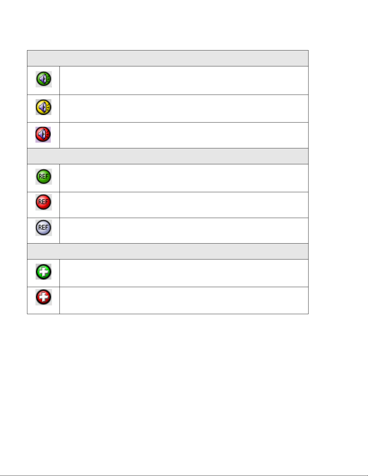
Icon #4 – Audio Status
Audio OK
(green)
Yellow alarm condition detected on 1 or more channels
(yellow)
Red alarm condition detected on 1 or more channels
Icon #5 – Reference
Reference OK. Mouse over to see the source of the reference, and its format, e.g.
External, NTSC
(green)
Reference missing. The reference is required for correct deglitcher operation.
(red)
Reference absent
(gray)
Icon #6 – Operation Mode
Hardware OK
(green)
Hardware Health Monitorin g (Fan1, Fan2, Hardware fault detected)
(red)
If this icon appears red, return the card to Miranda and specify the error code.
Section 2. The left portion of the window contains all the parameter groups, which become highlighted when they are
selected; the main panel (4) then displays the group’s set of parameters. Each of the groups is described in detail
below.
Section 3. The lower left corner of the window identifies the Preset currently in use or “Custom” if none is applicable.
Section 4. The main panel contains all the parameters specific to the group selected. It may contain several tabs to
help manage the different parameters.
Each of the panels assoc iated with the groups access ed from the buttons in Section 2, and show n in Section 4, is
described individually in the following sections.
14 | AMX-3981
Page 21
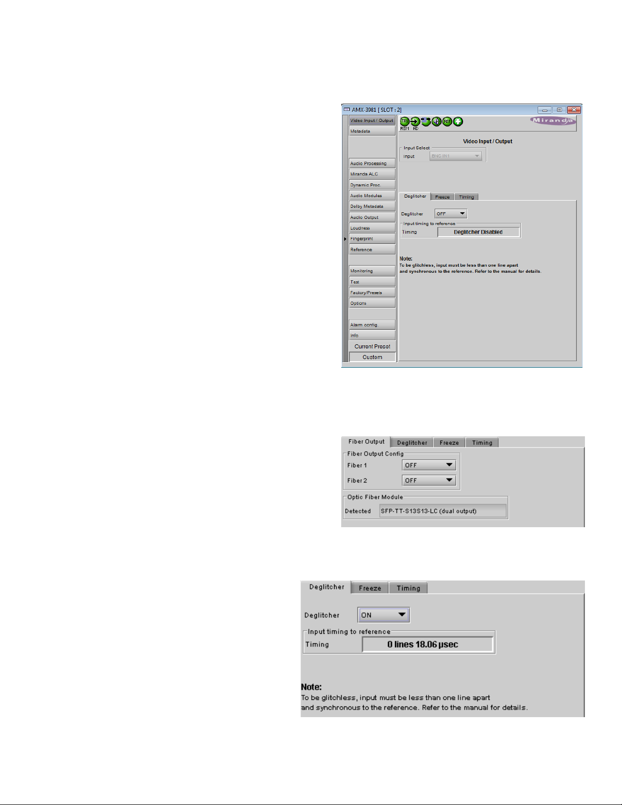
5.2 Video Input/Output panel
Figure
Figure
This panel allows input selection, control of the deglitcher and
freeze functions, and timing delay.
Input Select: use the pulldown list to select between the
copper input (BNC) and the fiber optic input (if available)
• The list will only be active if an Optic Fiber module is
installed in the rear panel. Otherwise it will be grey and
locked as BNC
GUIDE TO INSTALLATION AND OPERATION
5.2.1 Fiber Input/Output tab
This tab will only appear when a fiber optic module is
installed in the rear panel. The panel will be appropriate to
the type of module installed.
• The “Detected” data box shows the type of module that
the AMX-3981 has identified.
• The controls that appear allow the inputs and outputs
on the fiber module to be configured.
Options: OFF or ON
5.2.2 Deglitcher tab
When the Deglitcher is active, the card supports a
hot-switch between two signals without pr oduc ing a
freeze on the frame buffer, and without producing
artifacts on the output.
• In order to enable the deglitcher, the URS
signal must be selected as the reference in
the Reference panel (see section 5.11)
Deglitcher: select OFF or ON from the pulldown
5.2 Video Input/Output panel
Figure 5.3 Fiber Output tab
5.4 Video Input/Output – Deglitcher tab
AMX-3981 | 15
Page 22
GUIDE TO INSTALLATION AND OPERATION
Ref signal
Signal A
Signal B
Signal C
Signal D
Signal E
Signal F
Signal G
H=½ line
H=½ lineH = 0
Line = x
H = 0
Line = x+1
clean switch region #2
H = 0
Line = x-1
clean switch region #3
clean switch region #1
H=0
V=1
H=0
V=1
H=0
V=1
H=0
V=1
H=0
V=1
H=0
V=1
H=0
V=1
For this mode to function correctly, the following requirements must be met:
The offset from the VREF can be variable, but a distance of greater than 10 lines could create an artifact in the active
video. If the two signals are more than 1 line apart, we will see a vertical jump at the moment of switching that is
proportional to the number of vertical lines of offset between the two signals. This will last for only one frame. There
may also be problems in the transition when in the AFD automatic or forced mode.
When a reference is present and the deglitcher is active, the card reports the difference in timing between the input
and the reference when the transition occ ur s.
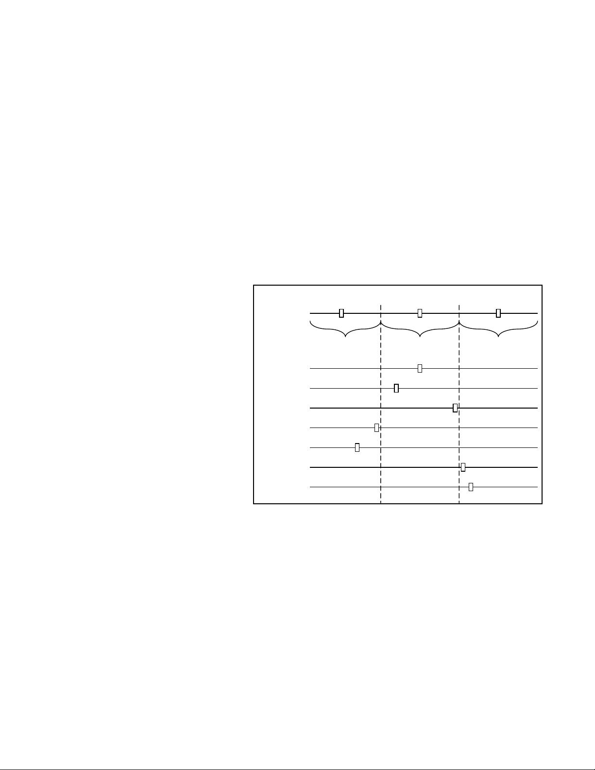
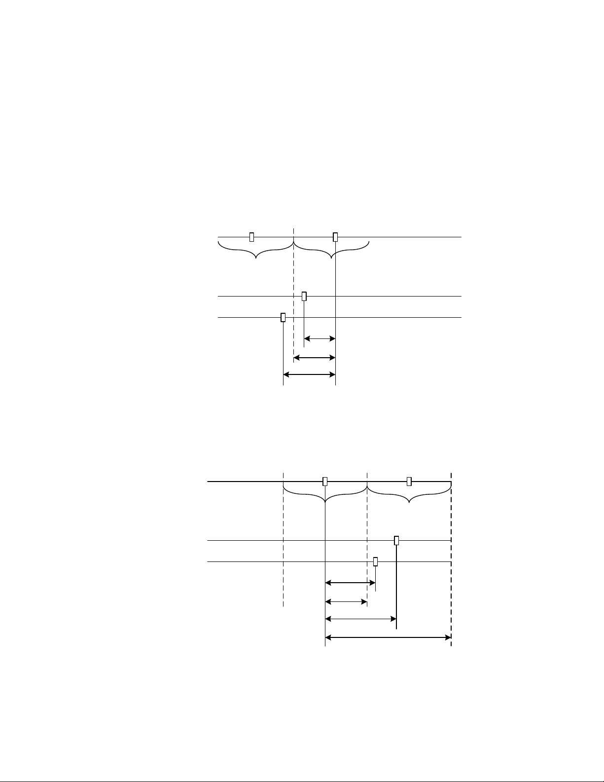
To perform a glitch-free switch between two
sources, they must be in the same clean switch
region. A clean switch region is contained within
± ½ line about an H=0 point in the reference
signal, as shown by the dotted lines in the
figure. There is a clean switch region centered
on every H interval. As you can see, vertical
alignment with the reference is not important for
the deglitcher to operate properly.
Referring to the figure on the right, you may
switch between signals A, B or C, without any
glitch, and also between signals DE and
signals FG. Any other transition, like AD,
will cause a vertical image shift for one frame.
To determine whether a clean hot switch is
possible, you need to determine whether the two
input signals lie in the same clean switch region. There are two ways to measure the position of the signals with
respect to the reference:
When the deglitcher mode is on, each of these sources will display the alignment offset between the reference signal
and the input signal. Knowing the offset for both input signals, you can determine if they are in the same clean switch
region. If so, any hot-switch between those two signals will be glitchless.
To determine the limits of a clean switch region, you must know the input’s line length in µs. The first region is
delimited by +½ line and -½ line of the reference. For exam ple, with an SD (525) signal the line length is 63.5 µs and
so the first region lies between -31.76 µs and 31.76 µs. Other regions can be found by adding or removing a multiple
of line length to the two boundaries.
Example: for an SD (525) input signal, we have these clean switch regions:
-1 line and -31.76 µs to 0 line and -31.76 µs
16 | AMX-3981
• The two inputs must be synchronized to the reference
• They must be phased within one line of each other
• They must be phased to within +/- ½ line of the HREF of the reference signal
• If the reference is missing when the deglitcher is activated, the Input timing to reference box will indicate
“Missing reference” in red, and the reference status icon at the top of the iControl window will turn red and show
the message “Reference missing”.
• If the deglitcher is OFF, the reference status icon will be grey, and its message will read “Reference absent”
• Use the deglitcher tab in iControl (InputDeglitcher)
• Use the controller menu in Annex 1 (videotimingin timing to ref).
Page 23
GUIDE TO INSTALLATION AND OPERATION
Ref signal
Signal A
Signal B
H=½ line H = 0
Line = 0
H = 0
Line = -1
H=0
V=1
H=0
V=1
-25us
-31.76us
-35us
clean switch region #1 clean switch region #2
Ref signal
Signal A
Signal B
H=½ line H = 0
Line = 0
40us
31.76us
50us
clean switch region #2
H=½ line
H=0
V=1
H=0
V=1
H = 0
Line = 1
H=½ line
clean switch region #3
95.28us
0 line and -31.76 µs to 0 line and 31.76 µs
0 line and 31.76 µs to 1 line and 31.76 µs
etc.
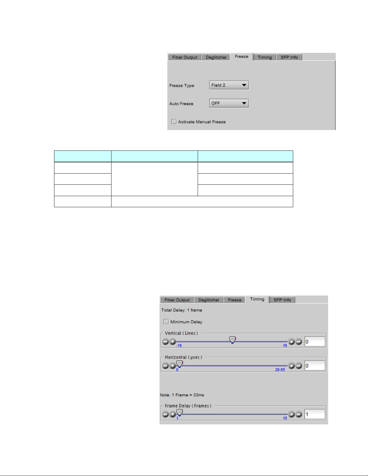
Practical examples:
Example 1: we have two SD (525) sources, one that indicates an offset of -25 µs with respect to the reference (A)
and the other an offset of -35 µs (B). We know that a clean switch region limit is present at -½ line, w hic h corresponds
to -31.76 µs. We can now determine that this switch will not be clean, because the two sources are on opposite sides
of the limit, and are therefore not in the same clean switch region.
Example 2: We have two SD (525) sources, one that indicates an offset of 50µs with respect to the reference (A) and
the other an offset of 40µs (B). We know that a clean switch region limit is present at + ½ line and another one at ½
line plus one line. These correspond to 31.76µs and 95.28µs. We can now determine that this switch will be clean,
because the two sources are inside the same clean switch region.
AMX-3981 | 17
Page 24
GUIDE TO INSTALLATION AND OPERATION
Freeze Type
Auto Freeze Mode
Manual Freeze Mode
Figure
Figure
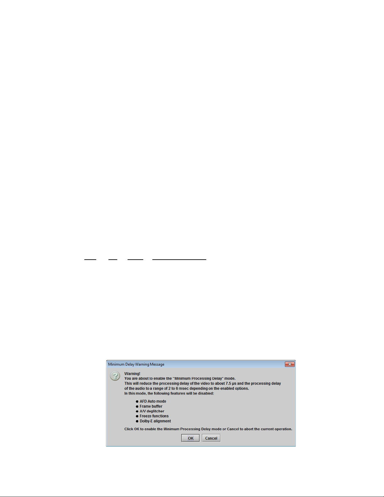
5.2.3 Freeze tab
Freeze type: This is a pull-down menu with four
options – FIELD 1, FIELD 2, FRAME and BLACK. It
determines the manner in which the AMX-3981
responds to a manual freeze, a video input switch
(“hotswitch” as defined by SMPTE recommended
practice RP-168, revised January 2002), a loss of
input signal or other input errors. The four possible
options yield the following results:
5.5 Video Input/Output – Freeze tab
• Field 1
• Field 2
• Frame
• Black
Auto Freeze: This pulldown (ON/OFF) enables or disables the auto freeze function. In Auto Freeze mode, a
reference must be present to ensure a glitchless output when a freeze is activated. There are only two freeze
possibilities in Auto mode: freeze to las t va li d Field or freeze to black. When Auto Freeze mode is disabled, the
content of the active picture will reflect whatever garbage is present at the input but, if a reference is present, the
output synchronization will be maintained to avoid unlocking downstream equipment.
Activate Manual Freeze: Select this checkbox to immediately freeze the output according to the selected Freeze
Type mode.
Note: The manual freeze setting is saved in the non-volatile memory of the card. If the manual freeze is activated and
the power is cycled, the card will start in freeze mode at the next power-up and the output will be invalid. Just turn off
the manual freeze to restore the output.
In all cases, audio will be muted when there is an
input error. See the audio section for more
information.
Freeze to last valid FIELD
Freeze to BLACK
Freeze to last valid FIELD 1
Freeze to last valid FIELD 2
Freeze to last valid FRAME
5.2.4 Timing tab
The Timing tab provides access to timing
adjustments which affect the signal outputs.
There are three slider controls, each with a data
reporting box which shows the current value, and
into which values can be typed directly. The total
delay is reported at the top of the window.
Vertical (lines): With this adjustment, a value
ranging from –16 to +16 lines compared to the
reference or the processing delay may be set.
This adjustment can be used in conjunction with
the horizontal timing adjustment.
5.6 Video Input/Output – Timing tab
18 | AMX-3981
Page 25
GUIDE TO INSTALLATION AND OPERATION
Horizontal (µsec): With this adjustment, a value ranging from zero to the equivalent of 1 horizontal line in the current
operating format compared to the reference or the frame boundary may be set.
Frame Delay (Frames): This parameter affects the overall processing delay of the card. It adds supplemental frame
delay to the current processing delay. This parameter will add a delay ranging from 1 to 15 interlaced frames (steps of
33 ms in 59.94 Hz and 40 ms in 50 Hz) to the current processing delay. Without a reference, the normal processing
delay is 1 frame. You can extend this delay up to16 frames using this slider. With a reference, up to 15 frames can be
added to the frame sync delay which depends on the timings between the input and the reference.
Note that, in order to compensate for the processing delay of a Dolby E and Dolby Digital decoder or a Dolby E
encoder installed on the AMX-3981 card, the frame delay must be set to at least one (1) frame. On the other hand, if
a Dolby Digital and Dolby Digital Plus encoder is installed, the frame delay must be set to at least seven (7) frames for
59.94 Hz formats and at least six (6) frames for 50 Hz formats.
Minimum Delay Mode
The minimum delay mode minimizes the processing delay of the video. The audio processing delay varies depending
on the presence of options. The following charts show the processing delay of audio and video for different video
formats and options.
Video Processing Delay:
SD: 20 µs
HD: 7.5 µs
3G – Level A: 3.8 µs
3G – Level B: 4 Lines + 4 µs
Audio Processing delay:
ALC DP Delay Delay using AES In
3G/HD/SD No No 2 ms 4 ms
3G/HD/SD No Yes 3 ms 5 ms
3G/HD/SD Yes No 3 ms 5 ms
3G/HD/SD Yes Yes 4 ms 6 ms
Note that using the AES inputs adds 2 ms to the delay, as shown in the table
Note: When minimum delay is active the following features will be disabled: AFD auto mode, frame buffer, A/V
deglitcher, freeze functions and DOLBY E alignment.
Enable the Minimum Delay checkbox to place the AMX-3981 in this mode. A pop-up warning will appear, explaining
the implications of using this mode:
AMX-3981 | 19
Page 26
GUIDE TO INSTALLATION AND OPERATION
F
Figure
5.2.5 SFP Info tab
When an SFP module is detected in the rear panel socket of
this AMX-3981, this tab shows identifying information:
• Type
• Part Number
• Serial Number
• Date Code
Additionally, some parameters are measured and their values
displayed here:
• Temperature
• Voltage (V)
• Optical Power (dBm)
• Wavelength (nm)
5.7 Video Input/Output – SFP Info tab
5.3 Metadata panel
This panel contains three tabs that give access to metadata processing on the AMX-3981 card:
• LTC
• GPI
• AFD
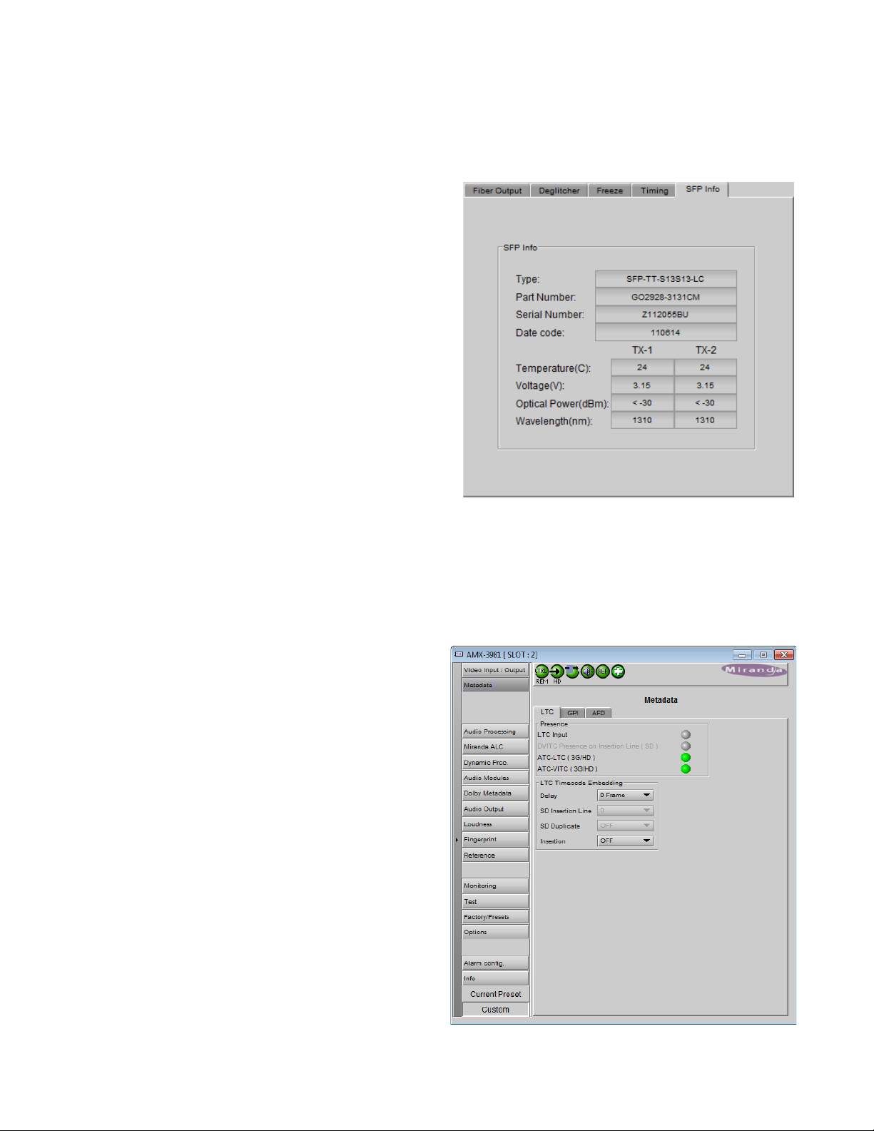
5.3.1 LTC tab
This tab controls LTC timecode embedding into the output
SDI data stream.
The Status icons indicate the presence of different time code
formats:
• LTC input (on the rear panel)
• DVITC (SD) embedded in the SDI input
• ATC-LTC (3G/HD) embedded in the SDI input
• ATC-VITC (3G/HD) embedded in the SDI input
The LTC Timecode Embedding section provides resources
to configure the embedding process.
Delay: [0, 1, 2, 3 frames]
SD Insertion Line: Select the line in which to embed LTC in
the SD-SDI output s ign al. Availa ble only when SD is
20 | AMX-3981
igure 5.8 Metadata Panel – LTC tab
Page 27
GUIDE TO INSTALLATION AND OPERATION
Figure
detected at the input.
[10-20 for 525; 7-22 for 625]
SD Duplicate: Select the line in which to embed a duplicate LTC in the SD-S DI out put signa l. Avai lab le on l y when SD
is detected at the input.
Insertion: In the case of 3H/HD signals, select OFF to disable insertion and pass incoming signals through
unchanged, or BOTH to embed both ATC-VITC and ATC-LTC from the LTC input on the rear panel into the output.
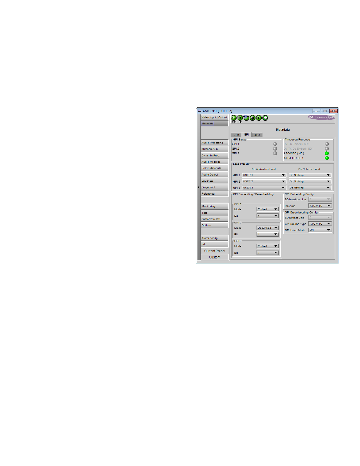
5.3.2 GPI tab
The AMX-3981 can both de-embed and embed GPI data
from/to timecode. As well, GPI inputs can be used to load
user presets on the AMX-3981 card, or reset loudness
measurements.
GPI status: the icons show the status of the three GPI
inputs on the rear panel.
Timecode Presence: Shows the time codes that are
available for embedding / de-embedding the GPI data.
Embed and De-embed are shown separately for SD
timecode, since they can be on different line numbers.
Load Presets: Use the pulldown lists to select what will
occur when each of the three rear-panel GPI inputs is
activated and released. Options are:
• Do nothing
• Load one of the five User Presets
• Reset the loudness measurement (see RESET on
page 49)
GPI Embedding / De-embedding: set up the embedding or
de-embedding of GPI data in the output and input data
streams. For each of the three GPIs:
Mode: use the pulldown list to select the operating mode for this GPI:
• OFF – the GPI is passed through untouched
• De-embed – a pre-defined user binary group bit from timecode within the incoming signal is de-embedded and
appears on the rear-panel GPI port
When De-embed is selected, use the Bit pulldown list to select which of the user binary group bits (1-16) will
be extracted to this GPI.
• Embed – the data placed on the rear-panel GPI port is embedded to a pre-defined user binary group bit within
timecode in the outgoing data stream.
When Embed is selected, use the Bit pulldown list to set which of the user binary group bits (1-16) will be
used to carry the GPI data.
GPI Embedding Config
SD Insertion Line (SD signals only): Select the line into which the GPI data will be embedded [10-20 for 525 and 7-22
for 625] provided DVITC time code is present.
Insertion (3G/HD signals only): select the ATC format [ATC-VITC, ATC-LTC or BOTH] into which the GPI data will be
embedded, provided the selected ATC format is present
5.9 Metadata Panel - GPI tab
AMX-3981 | 21
Page 28
GUIDE TO INSTALLATION AND OPERATION
Figure
If the source has no time code, a fixed time code of 00:00:00:00 will be generated in the appropriate format – DVITC
(SD), ATC-VITC or ATC-LTC (HD) – to carry the GPI and ensure that it is embedded.
Note that to accommodate on-card processing requirements, the GPI should be asserted no later that 1 ms before the
switch line in order to ensure that it is embedded in the next field.
GPI De-embedding Config
SD Extract Line (SD signals only): Select the line from which the GPI data will be de-embedded [10-20 for 525, 7-22
for 625] provided DVITC timecode is present.
GPI Source Type (3G/HD signals only): select the ATC format from which GPI data will be de-embedded [ATC-VITC,
ATC-LTC] provided the selected ATC format is present.
GPI Latch Mode: When no valid time code with embedded GPI data has been detected, the user has the option of
releasing the GPI outputs (Latch mode OFF), or holding the last valid de-embedded values (Latch Mode ON).
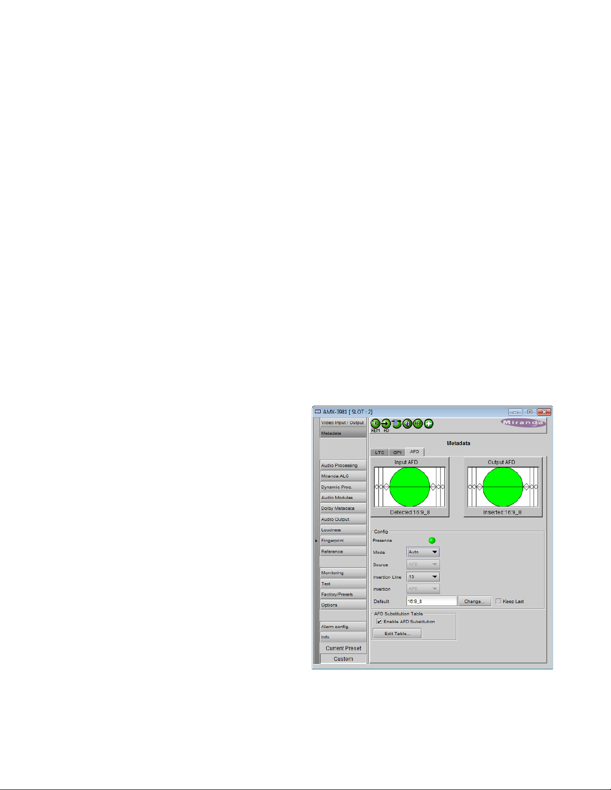
5.3.3 AFD tab
The Active Format Descriptor (AFD) flag is used to identify the aspect ratio and protected areas of a video signal. The
AMX-3981 manages the transfer of the AFD flag between its input and output, but does not use the AFD flag to
perform any picture manipulation. The AFD flag is implemented differently in HD and SD:
• In HD, the AFD flag (SMPTE 2016) is sent as an ancillary packet, normally found on line 11 in the vertical ancillary
space.
• In SD, the AFD flag is sent as a Video Line Index (VLI) signal (RP 186), as a Wide Screen Signaling (WSS) signal
(ITU-R BT.1119-2) for 625 only, and as an AFD packet (SMPTE 2016).
Note: The term AFD is used to represent all three types of
flags – SMPTE 2016 ancillary packet, VLI, and WSS.
The two graphics at the top of the panel show the input and
output AFDs and indicate the status (e.g. detected,
inserted). See ANNEX 6 – AFD Flags on page 109 for
information about AFD flags and terminology.
5.3.3.1 Config section
Presence: The status indicator turns Green when AFD is
detected on the input signal. On an SD input, the status
indicator will indicate the presence of AFD flags carried as
selected by the Source pulldown below, i.e. AFD, VLI or
WSS (for 625 sources only)
Mode: use the pulldown list to specify how AFD information
will be handled. Available choices are:
• Pass – pass the incoming AFD flag through without
change
• Insert – insert the ‘Forced’ AFD flag into the output,
overwriting any incoming flags
• Auto – if incoming flags are detected, pass them
through, otherwise, insert the “Default” flag
• Blank – ensure that no AFD flags are embedded in the
output stream.
22 | AMX-3981
5.10 Metadata - AFD tab
Page 29
GUIDE TO INSTALLATION AND OPERATION
Figure
Source: Selects the source of AFD information – options are AFD (SMPTE 2016), VLI (SD only) or WSS (for 625
sources only).
Insertion Line: The Insertion line is used to select on which line in the VANC the AFD packet (SMPTE 2016) will be
inserted. It is not necessary to specify the detection line since the card will automatically detect the incoming packet.
Insertion: The Insertion pull-down menu is used to enable or disable the insertion of AFD on the output. This feature
makes possible AFD conversion (SMPTE 2016 to VLI, VLI to WSS, VLI to SMPTE 2016, etc …) by allowing the user
to select the type of AFD flag to insert regardless of the programmed AFD source type:
• During HD operation, the Ancillary Aspect Ratio packet (SMPTE 2016) may be inserted. There is no AFD
conversion during HD.
• During SD operation, the Ancillary Aspect Ratio packet (SMPTE 2016), VLI, or WSS for 625 may be inserted
Default/Forced: this text box is labeled according to the mode selected in the Mode pulldown above
• In AUTO mode, it is labeled DEFAULT and shows the current default AFD code to be used if no valid AFD code is
detected at the input.
• In INSERT mode, it is labeled FORCED, and shows the code that is forced onto the output regardless of the
actual input code or if one is present
Change: Click the Change button to open the Select AFD panel showing the available AFD codes that could be used
as the default code/f orc ed AFD flag dur i ng AUT O /INS ERT modes. Click on one to select it, then click Apply or OK at
the bottom of the panel.
Keep Last: Select this checkbox to use the last AFD code detected at the input as the default code to be used in the
Auto mode when no AFD flag is detected. This box is disabled in the Insert mode.
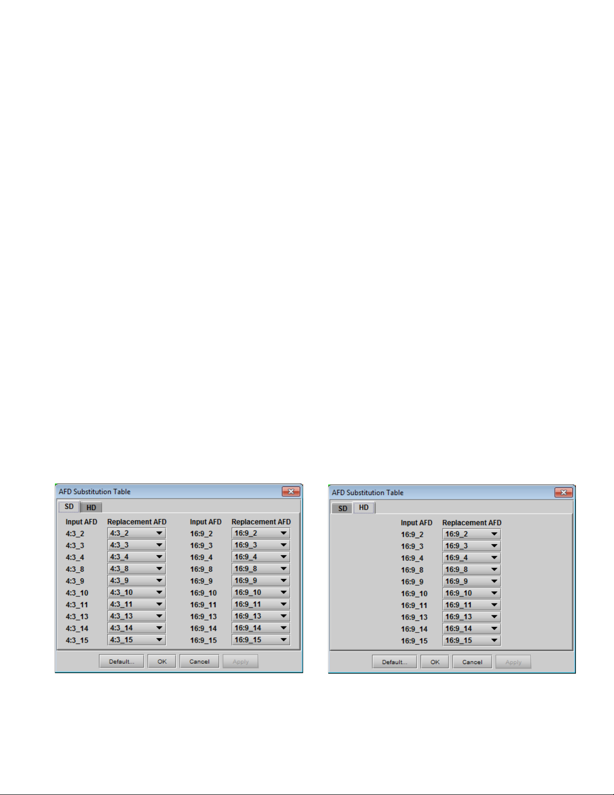
5.3.3.2 AFD Substitution Table
In the Auto mode, it is possible to set up a systematic AFD substitution scheme, where incoming AFD flags can
always be replaced by different flags, according to the AFD Substitution table.
• Select the Enable AFD Substitution checkbox to use this feature. The checkbox is only available in Auto mode
Click the Edit Table… button to open the AFD Substitution Table
5.11 AFD Substitution table
AMX-3981 | 23
Page 30

GUIDE TO INSTALLATION AND OPERATION
• The table has two tabs, one for SD inputs, and one for HD inputs.
• The table in each tab lists all possible Input AFD flags for that format, and beside each is a Replacement AFD
pulldown list that also lists all possible AFD flags.
• If the Replacement AFD does not match the Input AFD, the Replacement AFD
name is colored, so that it is immediately obvious which AFDs will be substituted.
Note: AFD substitution is ignored when no source flag is detected at the input. In this case, the Default flag is used.
5.3.3.3 Error and Warning Messages (SD only)
During SD operation, situations may arise when a conflict has occurred or may occur due to the enabling of certain
metadata parameters such as time code insertion, SMPTE 2016/VLI insertion, or Dolby Metadata insertion.
• A warning message will appear at the bottom of the Metadata / AFD panel.
• See for an example.
Here is a list of all possible messages that may be displayed and a description of the error or potential conflict.
“Dolby Metadata/VLI line insertion conflict. Refer to the user manual.” [Error in red]
This error occurs when the AMX-3981 has been programmed to generate Dolby Metadata and VLI on the same
line. The VLI signal is placed on line 14 for 525 and line 11 for 625. Make sure to select a different line number for
Dolby Metadata insertion.
“AFD insertion may overwrite incoming TC on insertion line. Refer to the user manual.” [Warning in blue]
Incoming DVITC time code may unknowingly be replaced by the insertion of SMPTE 2016 AFD flag. In order to
avoid any problems, make sure the line number of any incoming time code is known.
“Dolby Metadata insertion may overwrite incoming TC/VLI on insertion line. Refer to the user manual.” [Warning in
blue]
Incoming DVITC time code or VLI signal may unknowingly be corrupted by the insertion of Dolby Metadata. In
order to avoid any problems, make sure the line number of any incoming time code is known. If Dolby Metadata is
inserted on line 14 in 525 or line 11 in 625, make sure no time code or VLI is present in the input video signal.
“Dolby Metadata insertion may overwrite incoming TC on insertion line. Refer to the user manual.” [Warning in blue]
Incoming DVITC time code may unknowingly be corrupted by the insertion of Dolby Metadata. In order to avoid
any problems, make sure the line number of any incoming time code is known.
“Dolby Metadata/AFD insertion may overwrite incoming TC on insertion line. Refer to the user manual.” [Warning in
blue]
Incoming DVITC time code may unknowingly be replaced by the insertion of Dolby Metadata or the SMPTE 2016
AFD flag. In order to avoid any problems, make sure the line number of any incoming time code is known.
“VLI insertion may overwrite incoming Dolby Metadata on insertion line. Refer to the user manual.” [Warning in blue]
Incoming Dolby Metadata may unknowingly be corrupted by the insertion of the VLI flag. In order to avoid any
problems, make sure no Dolby Metadata is present on line 14 in 525 or line 11 in 625 when VLI is inserted.
5.4 Audio Processing panel
The Audio Processing panel provides full audio processing and delay parameters for up to 32 channels. The first 16
channels come from the embedded input channels. The second set of 16 channels comes from the output channels of
the following modules:
24 | AMX-3981
Page 31

GUIDE TO INSTALLATION AND OPERATION
Figure
• Dolby E and Dolby Digital decoder module(s) – see note
• Linear Acoustic’s upMAX
tm
module(s)
• Downmix
Note – when the Dolby E or Dolby Digital a nd Dol b y Digita l
Plus encoder is installed, some audio processing channels will
not be available because they are used in the Dolby encoder
module. In that case, an extra tab will appear in this panel to
advise the user of the situation.
5.12 Audio proc warning for Dolby encoders
The 32 processed audio channels can be assigned later to the Dolby E or Dolby Digital and Dolby Digital Plus
encoder modules, the 3G/HD output embedder, the SD output embedder, or the discrete AES outputs. To use the
“Audio Processing” functionality, you must enable the audio option.
You can configure the audio processor differently for an SD input than for a 3G/HD input. The card will remember the
different parameters and will load th em automatically without user interve nti on based on whether the video input is SD
or 3G/HD. Ensure the card has a video signal of the desired format before changing the configuration.
Group Detected section
Status indicators turn green when audio groups 1, 2, 3 or 4 are detected in the incoming signal. The Group Detected
warning color can be configured by the user in the Alarm Config panel (Sect. 5.16)
Discrete AES detected section: Status indicators turn green when an AES signal is detected on the indicated rear
panel AES input.
Signal Presence section
Signal presence indicators monitor the audio channel presence and are related to the Silence parameters defined in
the Ch XX/Silence tab (see details below): the indicator is green when an active signal is present and configurable
when a silence is detected according to the “no signal” threshold and the channel detection warning. The Signal
Presence warning color can be configured by the user in the Alarm Config panel (Sect. 5.16)
Under the Audio Proc tab are grouped controls for several aspects of the AMX-3981’s audio processing:
• levels
• delay
• silence detection
All of these parameters are adjusted individually for each channel, and channels are accessed in groups of four via
the first row of tabs in the panel. Below these tabs are the three tabs that access the parameters themselves.
In addition, control over Downmix is provided, and the status of all audio signals is monitored, under the appropriate
tabs.
AMX-3981 | 25
Page 32

GUIDE TO INSTALLATION AND OPERATION
Figure
Figure
5.4.1 Audio Proc – Levels tab
Grouped by pairs of channels, each channel has the
following controls:
Level (slider and input box): Sets the audio gain from -96
to 12 dB in 0.5 dB steps. For non-PCM audio, the level
value is overridden to 0 dB.
Mute (speaker button): Mutes the selected audio channel
Phase Invert: When checked, inverts the selected audio
channel phase.
Lock: “Locks” both channel sliders together for levels, so
that moving one slider moves the other one as well.
5.4.2 Audio Proc – Fixed Delay tab
Fixed Delay sub-tab: although the AMX-3981 automatically
matches audio and video throughput timing, provision i s
made for the user to insert an audio delay offset from the
nominal value, in order to deal with problems such as lipsync errors and audio phase alignment in the incoming feed.
For each channel, two sliders allow the delay to be adjusted.
• Coarse – adjusts the delay in milliseconds, over a
range of values that depends on the Reference and
the Frame Delay set on the timing tab in the Video
Input/Output panel (s ee pa ge 18), as follows:
With Reference:
Additional Adjustment Adjustment
Frame Delay Range Range
(59.94 Hz) (50 Hz)
0 0 to 2000 ms 0 to 2000 ms
1 -33 to 2000 ms -40 to 2000 ms
2 -66 to 2000 ms -80 to 2000 ms
3 -99 to 2000 ms -120 to 2000 ms
… … …
15 -500 to 2000 ms -600 to 2000 ms
5.13 Audio Processing - Channels - Levels
5.14 Audio Processi ng – Channels - Fixed delay
26 | AMX-3981
Page 33

GUIDE TO INSTALLATION AND OPERATION
Figure
Without Reference:
Additional Adjustment Adjustment
Frame Delay Range Range
(59.94 Hz) (50 Hz)
1 -12 to 2000 ms -19 to 2000 ms
2 -45 to 2000 ms -59 to 2000 ms
3 -78 to 2000 ms -99 to 2000 ms
… … …
15 -479 to 2000 ms -579 to 2000 ms
• Fine – adjusts the delay in audio sample increments, from -100 to +100 samples.
5.4.3 Audio Proc – Silence tab
This tab sets the card’s behavior in the event of a loss or
absence of audio signal. The Signal Presence indicators are
then triggered according to these sett in gs:
Silence Detect: select which audio channels to monitor for
audio silences by checking their boxes. This enables the
signal presence indicators to change color when there is no
signal present which activates the audio silence alarm.
Otherwise, when checkboxes are not checked, the signal
presence indicator turns grey and the audio silence alarm is
not activated
Threshold: Signal absence is declared when the signal level
is lower than the signal threshold for a duration longer than
the No Signal Delay. The threshold can be set to -72, -66,
-60, -54, -48 dBFS. The default value is –60 dBF S.
No Signal Delay: The period for which signal must be
continuously absent before an alarm can be triggered can be
adjusted from 3 to 255 seconds in preset steps: 3, 5, 7, 10,
15, 20, 30, 40, 50, 60, 90, 120, 180, 210, 240, 255 sec. The
default value is set to 15 seconds.
5.15 Audio Processi ng - Channels – Silence
5.4.4 Downmix
This tab provides resources to control the downmix of a “5.1 channel” surround-sound audio signal into an LtRt or
LoRo stereo pair. The 5.1 terminology refers to six discrete audio channels, with the low frequency effect (LFE)
channel of limited bandwidth designated as the “.1” channel. The downmix can be done using any of the 32 audio
channels processed by the audio processor using the Input Channels controls in the interface.
Input Channels: Use the 6 pulldowns to select the source channels for the downmix process.
Downmix:
Operating Mode: Use the pulldown list to select the downmix operating mode:
• OFF: Downmix is disabled. Output channels pass through unchanged.
• Manual: Downmix follows the downmix parameters manually configured by the user.
• Follow Metadata: Downmix follows the downmix parameters of the Metadata.
AMX-3981 | 27
Page 34

GUIDE TO INSTALLATION AND OPERATION
Figure
Level Normalization: use the pulldown to select the type
of normalization to be applied on the downmix output
level.
• OFF: Downmix output level is not normalized.
Clipping may occur depending on the input
channel levels and the selected mix levels.
• Level A: Downmix output level is normalized
based on the applied mix levels to provide a
uniform output over the range of mix levels
available. Clipping will never occur, even with
full scale input channels and mix levels.
• Level B: Downmix output level is normalized
based on the channel configuration to provide a
uniform output loudness between 3/2 and 2/0
programs. Downmixing a 3/2 program produces
a loudness attenuation compared to the same
program in 2/0 at the same input loudness. To
provide a uniform output loudness, a loudness
attenuation is applied only on 2/0 programs. If
the operating mode is Follow Metadata, the
channel configuration is given by the Dolby
Digital coding mode parameter in the metadata.
If the operating mode is Manual, the channel
configuration is given by the selected mix levels:
5.16 Audio Processing - Downmix
a 2/0 channel configuration is achiev ed b y
setting Center, Surround, and LFE Mix Levels to Mute. Any other combination of mix levels is assumed to
be a 3/2 channel configuration. Level-B normalization also includes Lev el-A normalization, based on the
applied mix levels. Clipping will never occur, even with full scale input channels and mix levels.
• This selection is not available when Oper . Mode is OFF.
Output Channels: Select the audio channels whose content will be replaced by the output of the downmix processor
• 7&8
• 15&16
• 23&24
• 31&32
• This selection is not available when the Operating Mod e is OFF (downmix disabled).
Manual Downmix Config / Default Me tada ta Config
The heading of this area of the panel changes depending on the selection in the Operating Mode pulldown above, but
the available controls are the same in both cases.
• Operating Mode = Manual – the controls are used to set up the Manual Downmix parameters.
• Operating Mode = Follow Metadata – the controls are used to set up the default downmix parameters for
situations where there is no metadata available.
Mode: this pulldown menu selects the downmix mode:
• LtRt: Enables the downmix of 5.1 channels into an LtRt (Left total Right total) matrix surround encoded
stereo pair. The input signals on the channel pair selected as the Output Channels are discarded.
• LoRo: Enables the downmix of 5.1 channels into an LoRo (Left only Right only) stereo pair, which is a
conventional stereo signal. The input signals on the channel pair selected as the Output Channels are
discarded.
28 | AMX-3981
Page 35

GUIDE TO INSTALLATION AND OPERATION
Dialnorm: this pulldown selects the dialog normalization level. Select OFF to prevent the downmix from applying the
dialnorm.
[OFF, -1 dBFS, -2 dBFS, -3 dBFS, ………, -31 dBFS]
Center Mix Level – sets the center channel downmix level to the selected value
[+3 dB, +1.5dB, 0 dB, -1.5 dB, -3 dB, -4.5 dB, -6 dB, Mute]
Surround Mix Level – sets the surround channels (Ls & Rs) downmix level to the selected value
[+3 dB, +1.5dB, 0 dB, -1.5 dB, -3 dB, -4.5 dB, -6 dB, Mute]
LFE Mix Level – sets the LFE channels downmix level to the selected value.
[+10 dB, +9 dB, +7.5, +6 dB, +4.5 dB, +3 dB, +1.5dB, 0 dB, -1.5 dB, -3 dB, -4.5 dB, -6 dB, Mute]
• Note: The LFE Mix Level pulldown sets the LFE downmix level for both Manual and Follow Metadata operation
modes, whether or not the metadata is present in the selected path.
The block diagrams below show the configuration of the LtRt surround sound downmixer and the LoRo stereo
downmixer.
Figure 5.17 LtRt Surround Sound downmixer Figure 5.18 LoRo Stereo downmixer
Follow Metadata Config:
This section reports on Metadata presence if the Follow Metadat a Operating Mode is selected. The four data boxes
below the Metadata status icon indicate the current mode, plus the values in use for Dialnorm, Center Mix Level and
Surround Mix Level.
• The user can choose whether to use the available Dialnorm value in the downmix process by selecting ON or
OFF from the pulldown list at the bottom of the section.
AMX-3981 | 29
Page 36

GUIDE TO INSTALLATION AND OPERATION
Figure
Figure
5.4.5 AES Inputs tab
The AMX-3981 processes 32 channels of audio. The
sources of the channels are:
Channels 1-16: Audio embedded in the incoming SDI
stream
Channels 17-32 Audio from the eight AES inputs on the
rear panel
Each of the rear panel AES inputs is provided with a sample
rate converter that will convert the sample rate of the AES
input to match the sample rate of the audio data embedded
in the incoming SDI stream
5.4.6 Status tab
The Status tab reports the type of audio present at the input
and the Dolby E alignment.
Audio Type Status:
• PCM – the audio channel carries PCM audio (orange)
• Dolby E – the audio channel carries Dolby E encoded
audio (blue)
• AC3 – the audio channel carries Dolby Digital encoded
audio (violet)
• NPCM – the audio channel carries Dolb y Dig it al Pl u s
or non-PCM other than Dolby E or Dolby Digital
(yellow).
Dolby E Alignment:
• When Dol by E audio is present, this panel will display
the offset/delay between the Dolby E and the video
output timing of the card. You may click the Auto Align
button to automatically adjust the audio timing delay to
ensure a perfect alignment with the video. This is
equivalent to changing manually the audio delay in the
audio processor. If you change the output timing of the
card or the video output format, you may have to realign the Dolby E .
• The offset is not available for any type of audio other
than Dol by E.
The measured Dolby E offset can be a positive OR a
negative value. A negative value indicates the Dolby E is in
advance compared to the video and additional delay should
be added to the audio channel pair.
A positive value indicates the Dolby E is late compared to the
video and the audio delay must be reduced for this channel
pair. Sometimes, the audio delay cannot be compensated
because it would mean to have an audio delay lower than the
5.19 Audio Processing – AES inputs
5.20 Audio Processing - Status
30 | AMX-3981
Page 37

GUIDE TO INSTALLATION AND OPERATION
Figure
processing delay of the card. In this case, you have to add an extra frame delay to the video to provide more range to
the audio delay.
5.5 Miranda ALC panel
Minimizing loudness differences between segments in a
playout channel is an important iss ue in a world wher e multiple
programs originating in different formats from different sources
must be integrated seamlessly. The Automatic Loudness
Control (ALC) option is the solution to this need. It uses
Miranda’s proprietary wideband ALC algorithm.
• Identified as AMX-3981-OPT-ALC-X, where X can be 2, 6, 8 or 16 input channels. The table shows the ALC
models available:
Model Description Program types supported
AMX-3981-OPT-ALC-2
AMX-3981-OPT-ALC-6
AMX-3981-OPT-ALC-8
AMX-3981-OPT-ALC-16
2-Channel ALC, up to 2 independent programs Mono, 2.0
6-Channel ALC, up to 6 independent programs Mono, 2.0, 3.0, 4.0, 5.1
8-Channel ALC, up to 8 independent programs Mono, 2.0, 3.0, 4.0, 5.1, 7.1
16-Channel ALC, up to 8 independent programs Mono, 2.0, 3.0, 4.0, 5.1, 7.1
Note: The ALC works with PCM audio. If non-PCM audio like Dolby E or Dolby Digital a nd D olb y Digit al Plus is fed to
the module, it will be ignored and all the program channels will be bypassed to prevent interference with the other
PCM audio channels.
5.5.1 Config tab
Channels per program
Pull-downs are available to select the number of channels
per program. Depending on the ALC model, you may have
different possible selections, from 1 to 8 channels per
program.
Input channels selection
An input shuffler allows any combination of the available
channels to be used as inputs to each ALC program.
Note: An input channel cannot be assigned to more than
one (1) program, and can only be used once within a
program.
Global Config
The Mode pull-down selects preset values for target, sliding
window and loudness units that apply to loudness
monitoring for all programs on this AMX-3981:
Mode Target
EBU R128 -23 3 sec LUFS
Short-Term
Time Window
Loudness
Unit
5.21 Miranda ALC – Config tab
AMX-3981 | 31
Page 38

GUIDE TO INSTALLATION AND OPERATION
Figure
A85 ITU BS.1770 -24 10 sec LKFS
ARIB TR-B32 -24 3 sec LKFS
Enable Loudness Monitoring turns ON the ALC input and output loudness monitoring for all programs.
5.5.2 PGM1-8 tabs
Loudness monitoring
When turned ON, the loudness meters display the program
input loudness (before ALC processing), the dynamic
correction applied by the ALC, the ALC limiter correction,
and the program output loudness (after ALC processing).
The input and output loudness are given in LUFS or LKFS,
depending on the modes selected in the Config tab.
Loudness meters are integrated over a “sliding-window”
period which is also mode-dependent.
Dynamic and limiter corrections are always given in dB.
Each correction meter is integrated over a period of 250
milliseconds.
ALC Presets
Three factory presets for the ALC are available to cover most
broadcast applications.
• Factory Light – The ALC applies low dynamic range
compression on the audio program content. The overall
response time is relatively slow, which reduces the ALC
ability to tightly follow the target output loudness. Using
this preset, the program content will sound a little more
dense, while keeping most of the original program
dynamic range.
5.22 Miranda ALC – PGM1, 2, 3, …, 8 tab
• Factory Standard – The ALC applies moderate dynamic range compression on the audio program content. The
overall response time is also moderate, which allows the ALC to follow the target output loudness quite well. This
preset is well-suited for most types of audio content. It is the factory preset loaded when loading the card default
parameters.
• Factory Heavy – The ALC applies high dynamic range compression on the audio program content. The overall
response time is relatively fast, which improves the ALC ability to tightly follow the target output loudness. Using
this preset, the program output content will sound much more dense, less dynamic.
Five user presets are also available to save and load custom configurations of the ALC. These presets are labeled
ALC 1 to 5 but the user can edit the preset names via the “Edit Labels” button.
We STRONGLY recommend starting with the ALC factory preset (Light, Standard, Heavy) that is closest to the
desired objective, then fine tuning it to reach the desired goal. This will minimize the troubles that will likely be
encountered as many adjustments interact.
ALC Bypass
Checking this box bypasses the ALC program processing, and the input channels pass through to the output
unaltered.
32 | AMX-3981
Page 39

GUIDE TO INSTALLATION AND OPERATION
Limiter Threshold
Fast Mode Threshold
Transient Threshold
Transient Threshold
Gate Threshold
Output Target
Fast
Time
Transient
Time
ALC Response Time
Transient
Time
ALC
Response
Time
ALC
Response
Time
Freeze
INPUT
OUTPUT
Target Loudness
Sets the target output loudness. This value sets the average output loudness, which means that due to the program
dynamics, the output loudness will move around the selected target. The units of measurement and the nominal
value, as well as the window size for the measurements (not shown on this panel) are set by the Mode pulldown in the
Config tab.
Although the nominal Target Loudness is reset according to the table above when the Mode is changed, the user may
change the value at any time using the pulldown, where the available range is -10 to -31 for all modes.
Here’s the time-domain response of the ALC:
ALC Pre-Amp Level
A pre-amp stage is available in front of the ALC to compensate for programs having an input loudness out of the ALC
tracking range (very low or very high input loudnes s ). The pre-amp level ranges from -20 dB to + 20 dB, in steps of 1
dB.
Fast Mode Response
The Fast Mode Response is optional and is enabled by checking the Enable box.
The ALC Fast Mode Response kicks in whenever the input loudness goes over the Fast Mode Threshold and
loudness is reduced, in a few milliseconds. The Fast Mode Threshold is given in dB with respect to the target
loudness and ranges from 2 to 12 dB, in dB steps.
Transient Mode Response
The Transient Mode Response is optional and is enabled by checking the Enable box.
The ALC Transient Mode Response kicks in whenever the input loudness goes over or under the Transient Mode
Threshold. The Transient Mode Threshold is symmetric with respect to the target loudness and ranges from 2 to 12
dB, in dB steps. When the input loudness is over the Transient Mode Threshold , loudness is reduced following the
rate set by the Speed pull-down. When the input loudness is under the Transient Mode Threshold, loudness is
increased, again following the Speed pull-down, which ranges from Slow (up to 15 seconds) to Fast (up to 4
seconds).
AMX-3981 | 33
Page 40

GUIDE TO INSTALLATION AND OPERATION
Figure
Response Time
Outside of the Fast and Transient modes ranges, the ALC performs loudness correction slowly, following the
Response Time. Response time values are : 5 sec, 10 sec, 15 sec, 20 sec, 30 sec, 45 sec, 1 min, 5 min, 10 min, 15
min, 20 min.
Freeze Threshold
The Freeze Threshold sets the threshold below which the ALC will not increase loudness This prevents quiet
portions of programs (and noise) from being unintentionally boosted. If the input program loudness is under the
Freeze Threshold for more than 30 seconds, the ALC will smoothly return to 0 dB of loudness correction.
Limiter Threshold
The Limiter Threshold will limit the output loudness under the selected threshold. This avoids unintentio na l clipp ing
of loud portions of programs. If the input program loudness is over the Limiter Threshold, the ALC will reduce the
loudness very quickl y, in 1 millisecond.
5.6 Dynamic Processing panel
This panel provides controls for dynamic processing of the
audio passing through the AMX-3981
• The Dynamic Processing Option (AMX-3981-OPT–DP)
must be activated to access this functionality. See
page 64.
Individual and independent controls are provided for each of
the 32 channels.
These parameters affect the output audio channels (HD/SD
embedded and AES), and the audio channels assigned to
the Dolby E encoder and the Dolby Digital and Dolby Digital
Plus encoder modules.
Note that, unlike the audio processing configuration, only
one (1) dynamic processing configuration is saved by the
card, regardless of the input format (3G/HD or SD).
• Access the individual channel controls through 4
master tabs and sub-tabs
The functionality of these controls is identical for each
channel, and is explained here.
The upper right-hand corner of each tab contains a graphic
depicting the transfer characteristic of the channel as
configured by the current dynamic processing settings.
Images will be shown below to illustrate the effect of the various controls
Mode
Use the pulldown to select the operating mode for this channel, from among these options:
• Mono: applies the dynamics processing settings only to the selected channel
• Stereo: applies the dynamics processing settings to the channel pair (e.g. 1 & 2, 7 & 8, etc.)
• Group 1: applies the dynamics processing settings only to the channel assigned to Group 1
• Group 2. applies the dynamics processing settings only to the channel assigned to Group 2
34 | AMX-3981
5.23 Dynamic Processing panel
Page 41

Dynamic Gain
0 dB 24 dB
Limiter Threshold
-10 dBFS -20 dBFS
Compression Ratio & Threshold
Click the Bypass Settings checkbox to bypass all the dynamics processing settings set up in this panel for this
channel.
Dynamic Gain
Sets the audio dynamic gain from 0 to 24 dB (in 1 dB steps) applied to
the selected channel. The dynamic gain is applied at the end of the
dynamics processing chain.
Limiter Threshold
A limiter is a type of compressor designed for a specific purpose, to limit
the level of a signal to a certain threshold. Whereas a compressor will
begin smoothly reducing the gain above the threshold, a limiter will
almost completely prevent an y addition al ga in abo ve t he threshold. A
limiter is like a compressor set to a very high compression ratio (typically
1/∞).
For example, if the limiter threshold is set to -20 dBFS and the input
signal level is -10 dBFS (10 dB above the threshold) , t he signa l lev el at
the output of the limiter will be -20 dBFS.
• Use the Limiter Threshold slider to set the threshold from -20 dBFS to 0 dBFS (1 dB steps).
Compressor
Audio compression is a method of reducing the dynamic range of a signal. All signal levels above the specified
threshold are reduced by the specified ratio. When the signal level exceeds the threshold, the compressor will begin
smoothly to reduce the gain, following the attack time, until the output level reflects the specified compression ratio.
When the signal level is below the threshold, the compressor will begin smoothly to increase the gain, following the
release time, until the output level matches the input level.
For example, if the compressor threshold is set to -20 dBFS and a ratio
of 1/2, and the input signal level is -10 dBFS (10 dB above the threshold),
the signal level at the output of the compressor will be smoothly reduced
to -15 dBFS (following the attack time). Then, if the input signal level
suddenly drops to -30 dBFS (10 dB below the threshold), the signal level
at the output of the compressor will smoothly go back to -30 dBFS
(following the release time).
Use the Attack Time pulldown to set the attack time. The attack time
specifies how fast the compressor will reduce the gain:
• Possible values: 1 ms, 5 ms, 10 ms, 20 ms, 40 ms, 80 ms, 160 ms.
Use the Release Time pulldown to set the release time. The release time specifies how fast the compressor will
increase the gain:
• Possible values: 48 dB/s, 36 dB/s, 24 dB/s, 18 dB/s, 12 dB/s, 9 dB/s, 6 dB/s
GUIDE TO INSTALLATION AND OPERATION
1/1.5 & -20 dBFS 1/8 & -60 dBFS
AMX-3981 | 35
Page 42

GUIDE TO INSTALLATION AND OPERATION
Expansion Ratio & Threshold
F
Use the Ratio pulldown to set the compression ratio (i.e. slope of the transfer curve). The compression ratio specifies
how much the output level changes with respect to the input level:
• Possible values: 1/1 (OFF), 1/1.25, 1/1.5, 1/1.75, 1/2, 1/3, 1/4, 1/8, 1/16
Use the Threshold slider to set the compression threshold (i.e. break point in the transfer curve). The compression
threshold specifies the level above which the compressor will process the signal.
• Range -60 dB to 0 dB
Expander
Audio expansion means to expand the dynamic range of a signal. It is basically the opposite of audio compression.
Like compressors and limiters, an audio expander has an adjustable threshold and ratio. Whereas compression and
limiting take effect whenever the signal goes above the threshold, expansion effects signal levels below the threshold.
Any signal below the threshold is expanded downwards by the specified ratio.
For example, if the expander threshold is set to -40 dBFS and a ratio of 2/1, and the input signal level is -60 dBFS (20
dB below the threshold), the signal level at the output of the expander will be reduced to -80 dBFS. Then, if the input
signal level suddenly increases to -30 dBFS (10 dB above the threshold), the signal level at the output of the
expander will go back to -30 dBFS.
Use the Ratio pulldown to set the expansion ratio (i.e. slope of the
transfer curve). The expansion ratio specifies how much the output level
changes with respect to the input level :
• Options available: 1/1 (OFF), 1.125/1, 1.25/1, 1.375/1, 1.5/1,
1.625/1, 1.75/1, 1.875/1, 2/1
Use the Threshold slider to set the expansion threshold (i.e. break point
in the transfer curve). The expansion threshold specifies the level below
which the expander will process the signal.
1.25/1 & -60 dBFS 1.75/1 & -40dBFS
• Range -80 dB to -40 dB
Dynamics for 1 minute.
Click the Dynamics for 1 minute button to display the dynamics processing in the meters at the bottom of the panel for
a period of one minute. Dynamics metering is enabled by groups of 16 channels: Channels 1-16 or Channels 17-32,
selected depending on the Channels tab selected at the top of the panel
igure 5.24 Dynamics for 1 minute display
• The right-hand portion of this section shows the output channels of the dynamics processor on level meters, as
found in the RALM panel.
36 | AMX-3981
Page 43

GUIDE TO INSTALLATION AND OPERATION
Figure
• The left-hand side shows approximately how much dynamic processing is being applied to the signal (by
amplitude) on a channel basis.
• The example shown above is the result of substantial compression being applied to Channel 1
5.7 Audio Modules panel
This panel displays the controls for an audio module that may optionally be installed in a
socket on the AMX-3981 card.
See Section 6 beginning on page 71 for detailed descriptions of all of the available
modules and their associated control panels.
5.8 Dolby Metadata panel
This panel provides resources for managing the flow of Dolby metadata through the AMX-3981.
Multiple layers of tabs allow the user to drill down to the various available controls. For notational purposes, the path
to a particular control panel will be described here as:
[layer 1 tab] → [layer 2 tab] → [layer 3 tab]
For example, the panel shown in the figure on the right would be described as:
[Config] → [Delay]
5.8.1 Config tab
Input Presence: Status icons are provided to indicate
sources where Dolby Metadata is present and valid. The
following are shown:
• VANC Stream
• RS-422B
• Decoder (grey if not installed)
Source: This area allows source selection.
• The currently-active pathway is shown in green.
Primary: Use this pulldown list to select the primary
metadata source for this path.
The pulldown list shows the same sources appearing in the
Input Presence section. The Decoder source will appear in
red if the module is not installed.
Note: When decoding PCM audio, the Dolby decoder does
not generate any metadata. If a decoder is selected as a
source for a specified metadata path, the generator on the
same path will be automatically turned ON when the
decoder is decoding PCM audio. The content of the
generator must have been previously configured. Refer to
“Generator automated mode” below for details.
5.25 Dolby Metadata panel
AMX-3981 | 37
Page 44

GUIDE TO INSTALLATION AND OPERATION
Figure
Backup: use this pulldown list to select the source that will be used if the primary source
becomes unavailable or invalid. In addition to the available primary sources, the list includes:
• Last valid – return to the last valid source used
• Blank – no metadata output
• Generator – use the interna l generat or
Generator: Use this pulldow n list to turn the internal generator ON or OFF. Turning it ON
selects it as the source. The generator creates a complete, specific set of metadata, which is
configured in the Generator tab.
Generator automated mode:
The generator is turned on or off automatically in specific conditions to avoid loss of metadata at the output stream.
There are two specific conditions which will trigger the automation behaviors:
1. When a Dolby decoder module is installed and selected as the metadata source of a path, the audio
metadata from a Dolby E input stream will be decoded and passed. When the decoder is fed with PCM audio,
the Dolby decoder will not provide metadat a. Inst ea d, the generator will be automatically turned on. It is the
responsibility of the user to configure the generator with the proper PCM metadata parameters.
2. When an upMAX
upMAX
tm
mode is dictated by the coding mode parameter of the probed metadata stream. When the
metadata stream coding mode is 2/0, the upMAX
tm
module is installed and configured to operate in Follow Metadata mode, the resulting
tm
mode is set to Upmix and the generator will be turned on
to generate 5.1 metadata for the upmixed audio content. It is the responsibility of the user to configure the
generator with the proper 5.1 metadata parameters. If the metadata stream coding mode is 3/2, the upMAX
mode is set to Pass and the generator will be turned off to let the input metadata stream go through. If the
coding mode detected is other than 2/0 or 3/2 or there is no metadata, the reversion mode is used. In that
case, the generator will be turned on for the Upmix and AutoMAX reversion modes, and off for Pass reversion
mode.
Note: No automation is provided for the generator content. The generator content is always under user
control and must have been previously configured if used in these conditions.
Hold: Use the pulldown to select Hold ON or OFF.
• ON – freezes the Metadata values used in the output bitstream
• OFF - allows the current metadata to pass to the output
Probe: this box shows where the audio metadata probing occurs in the path.
tm
5.8.1.1 [Config] → [Delay]
Through Coarse and Fine adjustments, a fixed delay can be
applied to the Metadata bitstream. It is useful when
processing, like watermarking, is applied to the audio signal
outside the AMX-3981. The delayed Metadata bitstream will
stay properly timed with its associated audio signal.
38 | AMX-3981
5.26 Dolby Metadat a - [Config] → [Delay]
Page 45

GUIDE TO INSTALLATION AND OPERATION
Figure
5.8.1.2 [Config] → [Probe]
The Probe function allows the user to view information about the Metadata in the program stream. There are no
controls in this panel or its subpanels, except for the program select buttons.
The Probe section at the left of the panel shows information about the data stream in the metadata path.
• The two parameters at the top indicate the Program Configuration and the Video Frame Rate of the
Metadata bitstream.
• Depending on the Program configuration, one to eight programs are included in a Metadata bitstream. The
Program Select zone al lows the selection of one Metadata program.
The text boxes below the program select buttons report on the data rate, coding mode and dialnorm value of the
selected program.
[Config] → [Probe] → [Audio Processing]
This panel reports the status of the audio
processing:
• DC Highpass Filter
• Bandwidth Lowpass Filter
• LFE Lowpass Filter
• Surround 90
• Surround Channel Attenuator
o
Phase Shift
5.27 [Config] → [Probe] → [Audio Processing]
AMX-3981 | 39
Page 46

GUIDE TO INSTALLATION AND OPERATION
Figure
Figure
[Config] → [Probe] → [Dynamic Range]
This panel reports the status of Dynamic Range
processing:
• Line Mode Profile
• RF Mode Profile
• RF Overmod. Protection
[Config] → [Probe] → [Bitstream Info]
This panel reports the status of the metadata
bitstream:
• Bitstream Mode
• Center Downmix Level
• Surr. Downmix Level
• Dolby Surr. Mode
• Copyright Bit
• Original Bitstream
• Audio Production Info
• Mix Level
• Room Type
Additional bitstream information is found in the
Extended BSI tab
5.28 [Config] → [Probe] → [Dynamic Range]
5.29 [Config] → [Probe] → [Bitstream Info]
40 | AMX-3981
Page 47

[Config] → [Probe] → [Extended BSI]
Figure 5.30 [Config] → [Probe] → [Extended BSI]
Figure
• Preferred Stereo Downmix
• Lt/Rt Center Mix Level
• Lt/Rt Surround Mix Level
• LoRo Center Mix Level
• LoRo Surround Mix Level
• Surround EX mode
• Converter Type
GUIDE TO INSTALLATION AND OPERATION
5.8.1.3 [Config] → [Generator]
The tab name includes a bracketed item (Factory 5.1 in the figure) indicating which metadata preset is currently
loaded in the generator.
The upper left Pulldown list sets the Program
Configuration. The text box below it shows the
Video Frame Rate, which is set automatically by the
card.
Use the Program Select buttons to select the
program to configure.
Use the Coding Mode and Dialnorm pulldowns to set
these parameters in the generator output.
[Config] → [Generator] → [Audio Processing]
This panel allows configuration of the audio
processing parameters :
• Extended Bitstream info 1
• Extended Bitstream info 2
• DC Highpass Filter
• Bandwidth Lowpass Filter
• LFE Lowpass Filter
• Surround 90
o
Phase Shift
• Surround Channel Attenuator
5.31 [Config] → [Generator] → [Audio Processing]
AMX-3981 | 41
Page 48

GUIDE TO INSTALLATION AND OPERATION
Figure
Figure
[Config] → [Generator] → [Dynamic Range]
This panel allows configuration of the Dynamic
Range processing parameters:
• Line Mode Profile
[None, Film Standard, Film light, Music
standard, Music light, Speech]
• RF Mode Profile
[None, Film Standard, Film light, Music
standard, Music light, Speech]
• RF Overmod. Protection
[Config] → [Generator] → [Bitstream Info]
This panel allows configuration of the metadata
bitstream info parameters. Use the pulldowns to
select the appropriate values:
• Bitstream Mode
• Center Downmix Level
• Surr. Downmix Level
• Dolby Surr. Mode
• Copyright Bit
• Original Bitstream
• Audio Production Info
• Mix Level
• Room Type
5.32 [Config] → [Generator] → [Dynamic Range]
5.33 [Config] → [Generator] → [Bitstream Info]
42 | AMX-3981
Page 49

[Config] → [Generator] → [Extended BSI]
Figure
Figure
• Preferred Stereo Downmix
• Lt/Rt Center Mix Level
• Lt/Rt Surround Mix Level
• LoRo Center Mix Level
• LoRo surround Mix Level
• Surround EX mode
• Converter Type
GUIDE TO INSTALLATION AND OPERATION
5.34 [Config] → [Generator] → [Extended BSI]
5.8.1.4 [Config] → [Presets]
Because there are many parameters to set for the
generator, it is convenient to be able to save a
configuration for easy recall. The Presets tab offers
several convenient functions for this purpose.
The AMX-3981 allows the user to save five
configurations. These are labeled META 1 to META
5 by default, but the user can edit the names via the
Edit Presets Labels… button at the bottom of the
tab, adding text in the brackets, e.g. META 3
(sample text).
In addition, the AMX-3981 is preloaded with two
fixed data sets named Factory 2.0 and Factory 5.1.
The Current Generator Preset databox at the top of
the tab reports the current preset in use.
• If all parameter values do not match the preset
values, the box will show “Custom”.
The Generator Presets pulldown gives access to all seven available presets. The two buttons to the right then allow
two options:
• Load – load the generator with the values stored in the preset, overwriting the current settings
• Save – overwrite the values stored in the preset with the values currently set on the card (only for the five user-
settable presets – the Factory presets cannot be changed).
5.35 [Config] → [Presets]
AMX-3981 | 43
Page 50

GUIDE TO INSTALLATION AND OPERATION
Figure
The Save Probe To pulldown gives access to the five user-settable presets. Once one is selected, clicking on the
Save button saves the values detected by the probe into the user presets, in effect setting the preset to match the
current program stream.
Note – If you attempt to save the card configuration to a User Preset when the Metadata generator settings do not
correspond to a Metadata Preset value ( i.e. if the Curr ent Gener ator Pres et dat a box shows “Cus tom”), you will
trigger a warning because of the way the Metadata Generator settings are saved. See page 56 for a complete
explanation. You may need to return to this panel and save the “custom” settings into a Metadata preset before you
can save the card configuration to a User Preset.
• Avoid this by getting in the habit of saving the Generator Metadata settings each time you change them.
The Metadata Profiles… button gives access to a panel that allows the user to copy the card settings from this AMX3981 to other AMX-3981 cards accessible via iControl.
The Copy profile from line shows the current AMX-3981 card.
• The Profiles column contains a pulldown that lists the profiles that are available to copy.
• The list includes the generator, plus the 5 metadata presets
You can save the selected profile to disk for future recall:
• Click the Save profile to disk… button and select a disk location and file name to save the file.
You can recall a previously-saved profile from disk and load it into the card:
• Click the Restore profile from disk… button and find the appropriate file
• Click Open to load the contents of the file into the current AMX-3981
The Copy profile to area shows all other AMX-3981 cards that have been detected on the iControl network.
5.36 Metadata Profile Copy window
44 | AMX-3981
Page 51

GUIDE TO INSTALLATION AND OPERATION
Figure
• The Profile column will show the same profile that was selected for the current AMX-3981 in the Profile
pulldown.
• Click the Select checkbox for any cards to which you wish to copy the profile, or select all of them using the
Select All checkbox in the column header. Note that you can only copy to cards with the same firmware release
number.
• Click Copy to transfer the selected profile to the selected recipient cards.
5.8.2 Input/Output tab
This tab provides resources to configure the input and output
selections and processing of metadata for the AMX-3981
card.
VANC Metadata Extractor
The card can extract a Dolby metadata stream from the
VANC interval according to the specified SDID (range = 01
to 09). The presence of the stream is reported in the
interface.
VANC Metadata Inserter
The card can insert a metadata stream in the VANC interval
of the output. Use the pulldown lists to configure the
metadata insertion.
Insertion: Enable metadata insertion
• Off: No metadata is inserted.
• Metadata: Metadata is inserted
Insertion Line: Select the VANC line in which the metadata
will be inserted. The range depends on the output format:
• 3G/HD: lines 9 to 20
• SD (525) lines 12 to 19
• SD (625) lines 8 to 22
SDID: Select the VANC metadata packet SDID to be inserted. The SDID is used to specify the relationship between
the VANC metadata stream and the first channel of its associated audio program.
SDID Associated channel pair
01 No association, or only one audio program
02 Channel pair 1&2
03 Channel pair 3&4
04 Channel pair 5&6
05 Channel pair 7&8
06 Channel pair 9&10
07 Channel pair 11&12
08 Channel pair 13&14
09 Channel pair 15&16
5.37 Dolby Metadat a – Input/Output tab
AMX-3981 | 45
Page 52

GUIDE TO INSTALLATION AND OPERATION
Figure
Note: If the card is configured to insert a special SDID at the output, any Dolby Metadata packets at the input with the
same SDID will be deleted. Any other SDID packets not inserted by the card will be passed through untouched.
5.9 Audio Output panel
This panel provides additional audio processing for the 16
audio channels embedded in the 3G/HD/SD output:
• audio channel shuffling
• level adjustment
• mixing
• audio embedding mode.
You can configure the audio output shufflers/mixers (3G/HD,
SD and AES) differently for an SD input than for a 3G/HD
input. The card will remember the different parameters and
will load them automatically without user intervention based
on whether the video input is SD or 3G/HD. Ensure the card
has a video signal of the desired format before changing the
configuration.
.
5.38 Audio Output panel
5.9.1 CH 1-2, CH 3-4, … CH 15-16 tabs
Each of these tabs provides all necessary controls for the output mixers. The example shown is for the Embedded
Output, CH 1-2, but all panels have the same controls.
Operation Mode (Off, A, SUM(A+B), Mix, Mix 4CH): This menu allows the source(s) of each output channel to be
selected – a single channel, the sum of two channels, a mix of two channels, or on the even-numbered output channel
only, a mix of three or four channels.
Off: The output channel is muted.
A: The output channel is the channel source (ABUS Select and Channel) selected in sub-menu SOURCE A.
SUM (A+B): The output channel is the sum of the two channels sources (ABUS Select and Channel) selected in
sub-menus SOURCE A and SOURCE B.
• If you select this option, the SUM (A+B) Level pull-down is activated, allowing you to reduce the level of the
summed output (0dB, -3dB or -6dB).
46 | AMX-3981
Page 53

GUIDE TO INSTALLATION AND OPERATION
Figure
Figure
Mix: The output channel is a mono mix of the (ABUS
Select and Channel) selected in sub-menus SOURCE A
and SOURCE B.
Mix 4CH: This mode allows a 3-input or 4-input mix on
the chosen even output. A standard 2-input mix is
available on the odd output. On the same tab, the two
selected sources of the even channel are mixed with the
one or two selected sources of the odd channel. The four
sources are mixed, with the level of each source adjusted
using its slider or data entry box. You can swap the odd
and even output by enabling the Channel Swap (1&2)
checkbox. Note that in the Mix 4Ch mode, if the Mute
box is checked, only the even channel sources will be
muted, the odd channel sources will still pass to the
output.
Note: in the case of SUM and MIX, if either of the
two input channels is non-PCM, the output will
always be SOURCE A
Mute: Mute the audio channel by checking this box. In
the MIX4Ch mode, checking this box will mute only the
sources of the selected output channel.
Source A & Source B: These sub-sections allow the source
channels (A and B) to be selected for each output channel.
5.39 Audio Output operating controls
ABUS Select: V selects the embedded input audio. This is the only choice available at this time.
Channel: Channel 1, …, Channel 16: selects the channel to be used from the selected audio source.
Level (dB): Sets the audio gain of the channel source from -96 to +12 dB in 0.5 dB steps. For non-PCM audio,
the level value is overridden to 0 dB.
5.9.2 Config tab
The tab contains only an Audi o Insert pu lld o wn.
Use the pulldown in this tab to enable (AUTO) or disable
(OFF) audio embedding in the output.
• When OFF is selected, no audio is em bedded in the
HD output.
• When AUTO is selected, only those audio groups
containing at least one aud i o channel will be
embedded at the output.
5.40 Audio Output - Embedded - Config tab
AMX-3981 | 47
Page 54

GUIDE TO INSTALLATION AND OPERATION
Figure
5.10 Loudness Panel
Note: In order to use the loudness measurement capabilities of the AMX-3981, the Loudness Option must be
installed. See Loudn es s Meas urem ent option on page 65 for details.
The AMX-3981 allows the user to measure the loudness of audio streams passing through it. The measurement
process is flexible:
• All major loudness standards are supported.
• The measurement standards can be customized if desired.
• Up to four programs can be measured at once.
• Each program can be selected from an internal AMX-3981 metadata path, or defined manually.
• Segment markers can be inserted from a variety of triggers.
• Log files of the measurements can be stored externally, for analysis using Miranda’s Audio Loudness Analyzer.
5.10.1 Loudness | Config panel
Global Config
All loudness measurements performed by this AMX-3981
conform to the same standard, which is selected here using
the Meter Mode pulldown.
Six options are available:
Standard Target
EBU R128-2010 -23 3 sec -8 dB LUFS
EBU R128-2011 -23 3 sec -10 dB LUFS
A85 ITU BS.1770.1 -24 10 sec N/A LKFS
A85 ITU BS.1770.2 -24 10 sec -10 dB LKFS
ARIB TR-B32 -24 3 sec -10 dB LKFS
Custom -31 to -1 1 to 15 sec -8, -10, N/A LKFS
Short-Term
Time Window
For the 5 defined standards, the other three pulldowns are
inactive, but display their preset values in gray.
If Custom is selected, the other three pulldowns are active,
and values can be chosen according to the user’s needs.
The range of available values is shown in the chart.
Global Control
The AMX-3981 can monitor loudness on up to four programs specified by the user.
• In this panel, select which programs will be active using the PGM 1 to PGM 4 checkboxes.
• The tabs for the selected programs will become active, allowing each program to be defined.
Relative
Gating
Loudness
Unit
5.41 Loudness panel – Config tab
48 | AMX-3981
Page 55

GUIDE TO INSTALLATION AND OPERATION
Figure
Enable Loudness Monitoring turns all loudness monitoring functions ON or OFF
RESET resets the measurements, and places a segment marker in the log file (but only if User Event is selected in
the Segment Marker area).
• Note that you can also program a GPI to trigger a loudness reset - the control is located on the Metadata | GPI
tab (see section 5.3.2 on page 21).
RUNNING / PAUSE shows the current status of the loudness monitoring.
• Click the button to change the status.
• PAUSE stops the measurement until the button is clicked again, but keeps the last value for logging and
measurement.
Segment Marker
Select the checkboxes corresponding to the events for which you want a segment marker inserted in the loudness log
file:
• User Event – a manually-triggered RESET (but not a PAUSE).
• GPI – a RESET triggered externally via GPI input.
• Dialnorm change – a change in Dialnorm value in the incoming metadata stream.
• Coding Mode Change – a change in the coding mode, either through the manual settings or detected in the
incoming metadata stream.
Note that segment marker triggers in one PGM will generate segment markers in the logs for all PGMs.
5.10.2 Loudness | PGM panel
Four PGM panels – PGM 1, PGM 2, PGM 3 and PGM 4 – are
available, each activated by selecting the appropriate
checkbox in the LOUDNESS-CONFIG panel.
Use these panels to define the programs whose loudness will
be monitored by this AMX-3981.
Program Settings
Operation Mode: Use the pulldown to select to source of the
program definition:
Manual: Use the Manual Coding controls to define the
program channel
Path: Use the path defined in the Dolby Metadata panel
(see section 5.8.1 on page 37)
Manual program definition:
Select Manual in the Operation Mode pulldown.
Select the coding mode (e.g. 2/0, 3/2L, etc.) from the Manual
Coding Mode pulldown
5.42 Loudness panel – PGM 1 tab
AMX-3981 | 49
Page 56

GUIDE TO INSTALLATION AND OPERATION
3/0
X X X 3/0L
X X X X 2/1
X X X 2/1L
X X X X 3/1
X X X X 3/1L
X X X X X
Assign inputs to the program channels using the Input Channels pulldowns
• For each program channel, input CH 1 to CH 32 can be selected
• Each input can only be selected once in a program.
• Only the program channels corresponding to the selected coding mode will be enabled
The chart shows the coding modes that are available, and the program channels that are enabled for each.
Coding Mode
Left Right Center LFE Ls Rs
1/0 X
2/0 X X
Program Channels
2/2 X X X X
2/2L X X X X X
3/2 X X X X X
3/2L X X X X X X
Metadata Path program definition
If Metadata from the path is selected as the source, the Manual Coding Mode pulldown is disabled.
The Program Select switcher allows the user to select from among up to eight available programs (program 1 is the
default selection).
Once a program is selected, its Dialnorm and Coding Mode are extracted and displayed in the data boxes below the
switcher.
Note that:
• If the user selects Metadata path as the source, but no metadata is present, the selection defaults to Manual
mode.
• In Manual mode, there is no dialnorm to extract.
Measurements
The Measurements area displays results from the loudness measurements performed on the selected program
according to the settings made in the Config tab. The three data boxes show these values:
• Short term (S) Loudness averaged over the short-term time window set in the Config tab.
• True peak MAX Maximum true peak level found in all selected input channels
• Momentary MAX Loudness averaged over a 400 ms sliding rectangular time window
50 | AMX-3981
Page 57

GUIDE TO INSTALLATION AND OPERATION
The chart shows a running plot of the last 15 seconds of the value of the Short Term (yellow trace) and Momentary
(green trace) loudness values. The bar graph at the right indicates the current Momentary value.
A reset, initiated by a user via the Reset button on the Loudness | Config tab, or via a GPI event (configured on the
Metadata | GPI tab; see Load Presets on page 21 for more information), will reset all of these measurements.
5.10.3 Loudness | Logging Panel
This panel monitors logging activity for all loggers connected to
the application server associated with this AMX-3981 and its
associated Densité frame.
• The Logging Activity icon will be GREEN when logging
activity is detected.
• The number of loggers connected to the appserver is
shown in the data box.
About Log Files
Loudness logs contain data for a period of up to 24 hours. New
log files are started:
• when the logging function is enabled
• every 24 hours after logging was enabled, until logging is
disabled
• when the reference changes
• when the global config is changed,
See ANNEX 6 - Loudness Logging and the Miranda
Audio Loudness Analyzer beginning on page 111 for
detailed instructions on activating logging and analyzing
the logged data files.
Figure 5.43 Loudness panel - Logging tab
AMX-3981 | 51
Page 58

GUIDE TO INSTALLATION AND OPERATION
Figure
5.11 Fingerprint panel
Fingerprinting technology on this card functions in
conjunction with iControl.
• iControl 4.0 and higher is require d .
AMX-3981 streaming is ON by default, but the management
of the stream is handled in iControl, and there is no local
control of the process at this card control panel, except to
select the window, and to turn streaming OFF if there are
problems with the stream or the network.
See the iControl Version 4.00 User’s Guide
(Miranda document 226-99M00-271) or later, for a
description of Fingerprint management in iControl.
The relevant text can be found in the section called
‘Lip-Sync Detection and Monitoring’ which is in the
chapter titled ‘Working with iControl as an Operator’
Zone
Select the area of the image within which fingerprint data will
be calculated and streamed.
• The selected area is shown as a blue outline on the control panel window.
Default Window – a factory default is specified which is applied consistently to all Miranda fingerprinting devices. It
places the window in the central “action area” of the image, generally avoiding letterboxes and static graphics that are
usually found in the periphery of the image.
Full Screen – opens the window to include the complete video image.
Start/Stop Line & Pixel – allows the user to create a custom window in response to particular or unusual image
content.
• The custom window can be no smaller than half the picture width and half the picture height, but can be placed
anywhere within the picture.
5.44 Fingerprint panel
52 | AMX-3981
Page 59

5.12 Reference panel
Figure
Figure
This group of parameters allows the selection of the
reference to be used by the AMX-3981.
Use the radio buttons in the Reference Source area to select
from the following options:
• Auto – this mode selects the first source detected in this
order of priority:
o URS
o Selected Input signal
• URS (Univers al Ref er ence Sig na l) – selects the internal
reference from the backplane
• Input – uses the currently-selected input signal.
URS Format – use the radio buttons in the URS Format area
to select whether the URS is OFF, 29.97 Hz or 25 Hz.
• When URS is OFF, the URS reference format source
cannot be selected, and will also be ignored by the
automatic detection mode.
Note: Make sure the input signal is locked to the selected
reference signal at all times.
GUIDE TO INSTALLATION AND OPERATION
5.13 Monitoring panel
5.13.1 Thumbnails tab
The thumbnail area displays thumbnail images for the inputs
and outputs selected in the Player area.
Player – Click the checkbox to display the thumbnail
Control – Click the checkboxes to apply the Mode, Format,
Quality and Refresh Rate settings to the these thumbnails.
Mode – select between Video mode and Test mode. Use
Video mode for normal operation.
Format – choose the thumbnail size: small, medium, large
Quality – choose the quality of the displayed image by
selecting Poor, Normal or HiQ (High Quality) from the
pulldown list
Refresh Rate – select the desired refresh rate from the pulldown box. The choices are:
[Fast, 1 sec, 2 sec, …, 9 sec, 10 sec.]
5.45 Reference panel
5.46 Monitoring - Thumbnails
AMX-3981 | 53
Page 60

GUIDE TO INSTALLATION AND OPERATION
Figure
Figure
5.13.2 RALM tab
The Remote Audio Level Meter (RALM) panel displays
audio output level meters for up to 8 channels. Channels
are displayed in pairs, so up to four meters will be present in
the meter display window. The source for each meter is
selected using the pulldowns in the RALM Remote Control
area at the bottom of the control panel.
• OFF
• Embedded CH 1&2 up to CH 15&16
The meter is divided into three zones, and the dividing
points and color of each zone are individually configurable
under the Meter Ballistics Config tab.
Speed – select the meter response from the pull-down list,
options are [ fast, medium, slow ]
5.13.2.1 RALM Connections tab
Use the radio buttons to turn the meter display ON (RALM)
or OFF for the indicated channels. The meter appears
directly above the controls.
Reset Counter: click this button to reset the overload
counter on the ALM display to zero. See the next section for
instructions on setting up the overload counter.
5.47 Monitoring - RALM tab
5.13.2.2 Meter Ballistics Config tab
Type – select a type of meter from the pull-down
list
Upper Zone Limits – s elect the cros sover le ve l
between the upper and middle zones of the meter
(the range of values shown in the pull-down list
depends on the type of meter selected)
Lower Zone Limits – s elect the cros sover le ve l
between the middle and lower zones of the meter
(the range of values shown in the pull-down list depends on the type of meter selected)
Color samples – the three samples show the current selected color for the upper, middle and lower zones of the
meter.
• Click on the color sample of a zone to open a color selection panel to choose a different color for that zone
Overload Cursor – The overload cursor appears on the meter as an arrowhead in the meter scale. The two pulldown
boxes set the position of the overload cursor on the left and right meters. If the audio level on that channel goes above
the cursor, the Overload Counter at the top of the meter is incremented.
The Overload Counter shows a running count of the number of overloads detected. The Overload level is shown by a
marker beside the meter, and its position can be set under the Meter Ballistics Config tab
5.48 RALM - meter ballistics configuration
54 | AMX-3981
Page 61

GUIDE TO INSTALLATION AND OPERATION
Figure
Figure
The Phasemeter (located at the bottom of the RALM meter display) is a
small meter that represents the phase correlation factor between the two
channels of a pair.
Note – The level and phase meters are disabled for channels carrying
non-PCM audio (Dolby E, Dolby Digital, Dolby Digital Plus or other nonPCM types).
180° 90° 0
5.49 RALM meter display
5.14 Test panel
This panel contains a pulldown that allows the user to select
an internally-generated test signal to replace the program
signal at the AMX-3981 output.
OFF: the program signal appears at the output, and test
signals are OFF
Color Bars and Tone: sends a 75% color bar test pattern
(100% white), along with audio test tones (a continuous tone
on right channel with pulsed tone on left channel in ever y
pair) to the AMX-3981 output.
Lip Sync: sends a special test signal comprising color bars
and tone plus a detectable element that is used to align
audio-video delays in a processing path. This AMX-3981
becomes the transmitter in the alignment path. A second
device (e.g. FRS-1801) will perform the measurement at the
other end of the path.
• The special test signal consists of 75% color bars
within which a white square is inserted every 4
seconds for a duration of 10 frames. Simultaneously
with the beginning of the first field of video containing
the white square, the 16 embedded audio channels
and the 8 AES outputs are pulsed with a tone lasting
5.50 Test panel
AMX-3981 | 55
Page 62

GUIDE TO INSTALLATION AND OPERATION
Figure
250 ms.
Figure 5.51 Lip Sync test signal appearance and timing
5.15 Factory/Presets panel
5.15.1 Factory/Presets tab
Factory Section
Load Factory: Clicking this button will restore the card to a
factory default state. Two checkboxes enable the user to
choose whether to include Parameters and/or Alarms in the
restoration process
• Note that User Presets are not changed
User Presets section
The AMX-3981 has memory registers which can hold up to 5
user-defined parameter settings.
The Current Preset box (at the bottom left corner of the
panel) displays the last loaded preset. Any change to the
card configuration after a preset is loaded will change the
display to "Custom" instead of the preset value.
Select any one of the five pres ets using the pull-down list.
The name of the currently-selected User Preset is shown on
the pulldown box.
Click Load to load the contents of the selected User Preset
into the AMX-3981. All parameter settings and values will be
replaced by the contents of the selected User Preset.
• The first 4 user presets can be recalled by GPI User
Preset 1 to 4.
Click Save to store the current parameter settings and values
from the AMX-3981 into the selected User Preset. The existing contents of the preset will be overwritten.
5.52 Factory / Presets panel
56 | AMX-3981
Page 63

GUIDE TO INSTALLATION AND OPERATION
How t
Figure
Note: if you see a pop-up warning box like this when you click Save, you will need to decide how to deal with the
Metadata Generator presets. Click on the Metadata FAQ button to learn more about this issue.
Briefly explained, a User Preset stores all the parameter values on the AMX-3981 card except the parameter
values for the Metadata generators. These values are stored in a separate set of registers, and the User Preset
saves the contents of these registers plus a pointer to the register that was most recently used. If you change any
of the Metadata values but do not update the Metadata register by saving it, the values referenced by the pointer
are not the current values. If you save to a user preset under this circumstance, the User Preset will not contain
the changed values, and they cannot be recovered if you later load the card from the preset.
The User Preset Save Alert panel wi ll be trigg er ed an y time you attempt to save when the Generator Metadata
values have been changed but not saved. You can tell when this is the case, as both the User Preset box on the
main panel, and the Current Generator Preset box in the Presets tab, as well as the Generator tab label, will all
read Custom
The warning box gives you three options for dealing with the situation:
5.53 User Preset Save Alert warning panel
o tell when the metadata generator settings have not been saved
• Option 1 – abort the save process, so that you can go back and manually save the metadata parameters
(see instructions on page 43)
• Option 2 – go ahead and save anyway, but be aware that if you recall this User Preset you will probably not
restore the current metadata generator settings
• Option 3 – Save the Metadata presets first, in the Metadata register whose name is displayed (it will be last
register that was used, and if it is one of the factory registers a Save will not be allowed, so you might want to
consider option 1), and then save the User Preset.
Use the radio buttons to select one of these options (option 1 is the default), and click OK to proceed.
AMX-3981 | 57
Page 64

GUIDE TO INSTALLATION AND OPERATION
Figure
Edit Presets Label…
Click this button to open a window where you can define the name assigned to
each user preset. This is the name that will appear on the pulldown in the User
Presets section. The labels will also be copied from card to card when a copy
profile is performed.
Profiles
This section provides the option to save and recover the entire card configuration (including user presets if desired) on
an external disk, or to copy it to another AMX-3981 card.
Click on Profiles to open the Profile Copy window.
5.54 Profile Copy window
Copy profile from
This line sho ws this AMX-3981 card, and identifies it b y App server, Densité fram e and slot number, card type and
firmware version.
The Profile column has a pulldown that allows you to select which profiles you will work with, and gives these choices:
• Current, User1, User2, User3, User4, User5, All
The Select column includes a checkbox (preselected checked) to confirm that you want to work with the current card.
58 | AMX-3981
Page 65

GUIDE TO INSTALLATION AND OPERATION
Figure
Figure
Save Profile to Disk…
Click this button to open a Save dialog allowing you to specify a
file name and location to which the selected profiles for this
card will be saved.
Hint - It is a good idea to create a folder for these files, because
they are not explicitly identified as AMX-3981 profiles, and will
be difficult to find and identify if not clearly named and
conveniently located.
• Click the save button once the name and location have
been identified in the Save box
• If the file is saved correctly, the Transfer Status box on
the right of the Copy profile from line will indicate
Succeeded against a green background:
5.55 Save Profile to Disk dialog
• If the file was not saved for some reason, the Transfer
Status box to the right of the Copy profile from line will
indicate Failed against a red background:
Restore profiles from disk…
Click this button to open an Open dialo g box within whi c h you
can locate and select a valid AMX-3981 profile file.
• Click Open to read the contents of the file and to
reconfigure this AMX-3981’s profiles according to its
contents
• While the reconfiguration is in progress, the Transfer
Status box on the right of the Copy profile from line will
indicate Working against a yellow background
• When the reconfiguration is complete, the Transfer Status
box on the right of the Copy profile from line will indicate
Succeeded against a green background
Copy profile to
5.56 Restore Profiles from Disk dialog
This line shows other AMX-3981 cards that are available on the iControl network, each identified by App server,
Densité frame and slot number, card type and firmware version.
The Profile colum n shows the sam e inform ation as is shown f or the current c ard in the Copy prof ile from line, i. e. one
of the following:
• Current, User1, User2, User3, User4, User5, All
The Select colum n includes a checkbox to identify the AMX-3981 cards onto which you will copy profiles from the
current card.
• For convenience, a Select all checkbox is provided in the column header
AMX-3981 | 59
Page 66

GUIDE TO INSTALLATION AND OPERATION
Figure
• Note that you can only sele ct AMX-3981 cards with th e sam e f irmware v ersion as the sourc e car d; cards wi th a
different firmware version wil l show N/A ag ainst a yello w back gr ound in the Transfer Status column.
Click Copy to copy the selected profiles from this card into the selected other AMX-3981 cards
• While the profile copy operation is in progress, the Transfer Status box on the right of the Copy profile to line will
indicate Working against a yellow background
• When the profile copy operation is complete, the Transfer Status box on the right of the Copy profile to line will
indicate Succeeded against a green background
5.15.2 Automatic Preset Recall tab
AMX-3981 offers the user the possibility to select a user
preset based on the status of the incoming audio.
Access to the User1 and User2 presets can be triggered
automatically when specific combinations of input audio
signals are detected at the AMX-3981 input.
Switching card parameters in mid-program is more complex
than switching them manually in an off-line situation because
of the need to minimize or eliminate any transition effects,
and is generally quite specific to the card configuration and
the audio modules that are installed. Because of this, a fully
automatic configuration of the feature is not possible, and
user involvement is required. Set-up instructions are given
below.
The Automatic Preset Recall (APR) feature uses the status
of audio appearing at the input audio channels to determine
whether activation of a preset is required.
The user selects whether to use the 16 embedded audio
channels, or the 8 discrete AES audios in the process, using
the radio buttons in the Input Audio Selection section of the
panel.
The user specifies the combination of audios that must
appear on all 16 channels using a concise Presence/Type
string notation in a data box, one for each of the two user presets.
• For reference, the current input Presence/Type string is shown in a data box.
• The current input status for each channel is also displayed in a color and text graphic.
5.57 Automatic Preset Recall tab
60 | AMX-3981
Page 67

GUIDE TO INSTALLATION AND OPERATION
Figure
The display and string notation used in the iControl panel is as follows:
Audio Type
Audio Not Present (blank) Dark Gray 0
PCM PCM Orange P
Non-PCM NPCM Yellow N
Dolby E DolbyE Blue E
Dolby Digital AC3 Fuchsia D
Dolby Digital Plus NPCM Yellow N
Don’t Care (only in string) (only in string) X
Audio Presence Detector section
Implementing this feature requires the use of an audio presence detector, since Audio Not Present is one of the
parameters used in the detection process. This is not the same as an audio silence detector, which finds quiet
portions in a present audio signal (the AMX-3981’s silence detectors are set up in the Audio Processing panel) .
Use the Threshold pulldown to set the level (in dBFS) below which the ADX-3981 will consider the audio to be absent.
Range: -72 (default), -66, -60, -54, -48
Use the No Signal Duration pulldown to set the time interval for which the audio must be continuously detected as
absent before the Signal Absent status will be confirmed and active.
Range: 33 msec (default), to 100 msec in steps of 10 msec.
Automatic Preset Recall section
To activate this feature, click Enable Preset Recall
• Always configure the User Presets 1 & 2 before activating this feature, as the card will try to reload the
previously saved presets every time you try to change the card’s configuration. First, uncheck Enable Preset
Recall, configure the card according to the first preset, save it and then proceed the same way for the second
preset. Finally, enable the Automatic Preset Recall by checking the Enable Preset Recall.
• Note that you may activate either Automatic Preset Recall as described here, or select a user preset to be
activated by a GPI in the Load Presets section of the Metadata | GPI tab (see section 5.3.2 on page Error!
Bookmark not defined.), but only one of these may be active at a time. If User Preset activation via GPI is
active when you click Enable Preset Recall in this tab, a warning box will appear to remind you that enabling
this function here will disable the User Preset activation via GPI, and give you the choice to proceed, or to
cancel the selection.
Audio Channel Presence/Type Graphic
Label Color Code
5.58 Presets selection warning
Presence/Type
string character
AMX-3981 | 61
Page 68

GUIDE TO INSTALLATION AND OPERATION
Figure 5.59 Relative position of audio presence and type detectors
Audio Conditions – type a Presence/Type string into the data box for each of the presets that you wish to recall
automatically. Priority will be given to the first condition (USER 1). For example, if you want to do something when 5.1
audio is detected and something else when it is not detected, define the audio condition for 5.1 as the first condition.
The string represents the input configuration that will trigger the preset.
• A useful way to determine the appropriate entry is to set up the inputs to the configuration of interest, and then
copy the string that appears in the Current Presence/Type String data box into the User Preset data box. Note
that unused channels should be set to ‘X’ (don’t care) rather than 0 (absent).
While you are typing, note that:
• Only the characters that are significant can be typed; other keystrokes have no effect
• Characters are not case sensitive, although they appear as capitals in the databox.
• Click and drag to select one or more characters to type
• If you stop typing before filling all the selected character spaces, all remaining spaces will be filled with X (i.e.
don’t care) once you move the focus away from the box.
• The AMX-3981 will automatically detect conflicts, i.e. audio conditions that could call both presets
simultaneously. This could arise because of Don’t Care situations, or because the same string was accidentally
entered in both preset boxes. The most recently entered string will appear in red and will not be active. In case
of conflicts, the User Preset 1 condition will have priori t y.
Delay – set the delay between the detection of the condition that triggers the loading of a preset, and the actual
execution of the preset.
• The range in the scroll box is from 0 msec up to 500 msec, continuously variable.
• For AMX-3981, the default value is 33 msec, but the optimum value really depends on the application.
The Delay parameter is used to delay the loading of a User Preset into the card’s hardware. The delay range will be
from the fastest audio condition detection time to the longest processing delay of the card.
To begin, note that the Audio Type detector and the Audio Presence detector are both located at the input to the card:
The idea is to calculate the time delay as the audio passes through the AMX-3981 between the time at which the
audio condition is detected, and the time when the audio arrives at the location where the changes in processing need
62 | AMX-3981
Page 69

GUIDE TO INSTALLATION AND OPERATION
Figure 5.60 Application for automatic
preset recall
to be applied. The new preset should only be applied then, so that the processing change is applied only to the new
audio type.
Each card preset may contain hundreds of parameters: some are used to configure input parameters and others
output parameters. Unfortunately, all changes are applied more or less at one time, so some compromise is often
required when processing delays through the card are relatively long, such as in Dolby Digital and Dolby Digital Plus
encoding applications. Understanding what processing changes are required, and where those changes are applied in
the signal path through the AMX-3981, will help in making the most effective choice of delay time.
Most of the time, the different presets are nearly identical and only a few parameters will change from one preset to
another. Obviously, if the preset needs to control input and output parameters at the same time, it will be impossible to
select a perfect Delay.
Application for the Automatic Preset Recall:
Figure 5.60 shows the application. When DV is present on
embedded input channels 7-8, it is passed to the output. When
not present, a downmix version of the main 5.1 will be used. It
has been determined by the customer that the audio level on the
DV channels is always above -72 dBFS because of the noise
floor. If it goes below that threshold, we can assume there is no
audio present.
User Preset 1 will be recalled when DV is present on the
embedded audio input channels 7-8. The embedded audio
output shuffler for channels 7-8 will be programmed to pass the
input channels 7-8.
User Preset 2 will be recalled when DV is silent on the
embedded audio input channels 7-8. The embedded audio
output shuffler for channels 7-8 will be programmed to pass the
output downmix channels 15-16 made from channels 1-6.
The No Signal Duration will be set to 30 msec and the Threshold
to -72 dBFS. Assuming the total processing delay of the AMX3981 is set to 66 msec to give enough reaction time between the
detection of the silence and the application of the preset, the
Automatic Preset Recall should be configured as shown in the
picture below:
The delay to apply the preset has been optimized to take into account the No signal Duration, the total
processing delay of the card and the internal reaction times of the card. Determining the accurate preset
Delay to apply is rather complicated. Please contact our Technical Support department if you experience any
difficulties.
AMX-3981 | 63
Page 70

GUIDE TO INSTALLATION AND OPERATION
Figure
5.16 Options panel
Three options are available for the AMX-3981:
• Dynamic Processing Option (AMX-3981-OPT-DP)
• ALC Option (AMX-3981-OPT-ALC-X)
• Loudness Measurement Option (AMX-3981-LM)
To activate each of thes e o ptio ns , you m ust
• Obtain a license key from Miranda Technologies Inc.
• Type the license key in the Enter Key box
• Click on ENABLE OPTION to enable the option’s features.
5.16.1 Dynamic Processing option:
This option enables the audio dynamics processing
functionality of the AMX-3981.
5.61 Dynamic Processing option
64 | AMX-3981
Page 71

5.16.2 ALC option
Figure
Figure
This option enables the Automatic Loudness Control feature
of the AMX-3981.
Note that this option is available for 2, 6, 8 or 16 channels.
A separate license key is required for each of these, and the
data window below the Enter key data box will indicate which
is currently enabled, e.g.:
ALC AMX-3981-OPT-ALC-16 for the 16 channel option
If the currently-enabled option is 2, 6, or 8 channels, the
Enter key data box will be available to upgrade to a greater
number of channels.
GUIDE TO INSTALLATION AND OPERATION
5.62 ALC option
5.16.3 Loudness Measurement option
This option enables the Loudness Measurement feature of
the AMX-3981.
5.63 Loudness Measurement option
AMX-3981 | 65
Page 72

GUIDE TO INSTALLATION AND OPERATION
Figure
5.17 Alarm Config panel
This panel allows the alarm
reporting of the AMX-1981 to be
configured. The panel opens in a
new window when the button is
clicked, and can be resized if
needed.
The panel is organized in
columns.
Status/Name
This contains an expandable
tree listing all the alarms
reported by this AMX-3981 card.
• Each alarm name includes
an icon that shows its
current status
• Some alarms may be text-
only and the alarm status
is shown in the name and
not by a status icon
The Card LED, Overall alarm
and GSM contribution columns
contain pulldown lists that allow
the level of contribution of each
individual alarm to the alarm
named in the column heading to
be set.
• If there is no arrowhead in
the box, there is no
pulldown and the alarm is
not user-configurable
Card LED
This column allows configuration
of the contribution of selected
individual alarms to the status
LED located on the front card
edge. The Card LED status is
shown at the bottom of the alarm
tree in the Status/Name column.
Overall Alarm
This column allows configuration of the contribution of each individual alarm to the Overall Alarm associated with this
card. The Overall Alarm is shown in the upper left corner of the iControl panel, and also appears at the bottom of the
Status/Name column.
GSM Contribution
This column allows configuration of the contribution of each individual alarm to the GSM Alarm Status associated with
this card. GSM is a dynamic register of all iControl system alarms, and is also an alarm provider for external
applications. The possible values for this contribution are related to the Overall alarm contribution:
5.64 Alarm Configuration panel
66 | AMX-3981
Page 73

GUIDE TO INSTALLATION AND OPERATION
Figure
• If the Overall alarm contribution is selected as Disabled, the GSM alarm contribution can be set to any available
value
• If the Overall alarm contribution is selected as any level other than disabled, the GSM contribution is forced to
follow the Overall Alarm.
Levels associated with these alarms:
The pulldown lists may contain some or all of the following options:
The alarm makes no contribution (black icon)
The alarm is of minor importance (yellow icon)
The alarm is of major importance (orange icon)
The alarm is of critical importance (red icon)
The alarm exists but has no effect (used for text and composite alarms)
Shortcut: if you click in one of the Set All boxes beside a section heading, you will open a pulldown that lets you
assign a level to all alarms in that section of the column simultaneously.
Once the alarms are configured, you may accept the changes or discard them:
Log Events
iControl maintains a log of alarm events associated with the card. The log is useful for troubleshooting and identifying
event sequences. Click in the checkbox to enable logging of alarm events for each individual alarm.
At the bottom of the window are several other controls
Overall alarm and GSM contribution follow card LED
Click in the checkbox to force the Overall alarm and GSM contribution to be identical to the Card LED status
• All Overall alarms and GSM contributions for which there is a Card LED alarm will be forced to match the Card
LED alarm
• All Overall Alarms and GSM contributions for which there is no Card LED alarm will be forced to Disabled
A warning box will open allowing you to confirm the action,
since it will result in changes to the configuration and there
is no undo function.
5.65 Warning for Follow LED change
AMX-3981 | 67
Page 74

GUIDE TO INSTALLATION AND OPERATION
Figure
Figure
Copy to other cards
Click this button to open a panel that allows the alarm
configuration set for this card to be copied into another AMX3981 card.
• Select one or more destination cards from the list in the
window by clicking in the checkboxes, or all of them by
clicking in the All checkbox
• Note that when you do a Copy Profile for this card (see
Sect.5.15), the alarm configuration is copied along with
all the other settings.
Get alarm keys
Click this button to open a save dialog where you can save a file
containing a list of all alarms on this card and their current
values, along with an Alarm Key for each. The alarm keys are
useful for system integration and troubleshooting.
• The file is saved in .csv format
OK, Apply, Cancel
• OK accepts the settings and closes the window once the card confirms that there are no errors.
• Apply accepts the settings, but leaves the window open
• Cancel closes the window without applying any changes, and leaves the previous settings intact.
5.66 Copy to Other Cards window
5.67 Get Alarm Keys dialog
68 | AMX-3981
Page 75

GUIDE TO INSTALLATION AND OPERATION
Figure
Figure
Figure
5.18 Info panel
When the AMX-3981 is included in an iControl environment, certain information about the card should be available to
the iControl system. The user can enter labels and comments that will make this card easy to identify in a com plex
setup. This information is entered into data boxes in the Info control panel.
Rear Type: specifies the rear module currently
installed.
Optic Fiber Module: Identifies the optic fiber module currently
inserted in the fiber module socket on
the rear panel (only if installed).
Audio Module: Identifies the audio module currently
installed on the AMX-3981, if any.
Label: type the label that is shown for this
AMX-3981 when it appears in iControl
applications
Short Label type the short-form label that iControl
uses in some cases (8 characters)
Source ID type a descriptive name for this AMX-
3981
Comments: type any desired text
The remaining data boxes show manufacturing information
about this card.
Three buttons in the pan el give acces s to other infor m atio n.
• Details…: Reports the Firmware version, service version, and
panel version for this card
• Advanced…: Shows the Miranda LongID for this card. The Miranda
LongID is the address of this AMX-3981 in the iControl network.
5.68 Info panel
5.69 Details window
5.70 Advanced window
AMX-3981 | 69
Page 76

GUIDE TO INSTALLATION AND OPERATION
Figure
• Remote System Administration – opens the Joining Locators window,
which lists remote lookup services to which this AMX-3981 is registered
Add: Force the iControl service for this AMX-3981 to register itself on
a user-specified Jini lookup service, using the following syntax in the
data box:
jini://<ip_address>
where <ip_address> is the ip address of the server running the
lookup service, e.g.:
Remove: select one of the services listed in the window by clicking on it, and click Remove to open a query
box allowing you to delete it from the window.
5.71 Joining Locators window
70 | AMX-3981
Page 77

GUIDE TO INSTALLATION AND OPERATION
Figure 5.49
Figure
Decoder
6 Audio Modules
The AMX-3981 supports the use of a single audio processing module, user-installed into a socket on the main circuit
board.
• See Annex 4 beginning on page 105 for a description of the module installation and removal procedure
A number of different modules are available, allowing the functionality of the AMX-3981 to be customized.
This section of the manual describes each of the available modules in detail.
Module Description See section
MOD-DOLBY-DEC-2 Dolby E and Dolby Digital decoder 6.1 on page 71
MOD-DOLBY-ENC-D-2 Dolby Digital and Dolby Digital Plus encoder 6.2 on page 74
MOD-DOLBY-ENC-E Dolby E encoder 6.3 on page 76
MOD-LA-DUP-701 Upmixing using Linear Acoustic Technology upMAXTM 6.4 on page 78
MOD-LA-ALC-N*
MOD-LA-ALC-N*-DUP
MOD-JA-ALC-N*
MOD-JA-ALC-N*-DUP
* N = 2, 6 or 8, referring to the number of channels processed.
N-channel ALC licensed b y Linear Acous tic
N-channel ALC and upmix licensed by Linear Acoust ic
N-channel ALC licensed by Jünger Audio
N-channel ALC licensed by Jünger Audio & upmix by Linear Acoustic
6.1 Dolby E and Dolby Digital decoder
• Identified as MOD-DOLBY-DEC-2 on the module tab.
The decoder supports Dolby E, Dolby Digital or PCM
signals. Any other non-PCM signal will be lost through the
decoder module; its outputs will be muted.
For a Dolby E input signal, the decoder outputs a metadata
bitstream which may be used by the audio processing and
the audio modules, embedded in the 3G/HD and SD outputs,
or sent to the RS-422 output. See the Dolby Metadata tab.
A selector is provided at the Decoder input, but the output
channels of the Decoder are routed to the internal channels
1-8, 9-16, 17 to 24, or 25-32, with a mapping related to the
input Program Configuration and Coding Mode.
6.5 on page 80
6.6 on page 89
Audio Modules - Dolby Decoder control
6.1.1 Control tab
The Bitstream Detection Mode dictates the action taken by
the decoder for each type of input bitstream.
In Auto mode, the decoder automatically recognizes and
decodes PCM, Dolby Digital or Dolb y E input bitstreams. If
Dolby E only is selected, the decoder recognizes and
decodes only Dolby E bitstreams; otherwise the decoder
outputs are muted. The same behavior applies for the Dolby
6.1 Audio Modules - Dolby E and Dolby Digital
- Control
AMX-3981 | 71
Page 78

GUIDE TO INSTALLATION AND OPERATION
Figure
d
Digital only selection. If Mute (OFF) is selected, all outputs are muted for any type of input bitstreams; the Mute
mode disables the Dolby decoder.
The Input Selection determines the Dolby decoder input channel pair. See Audio Processing/AES Inputs for the
input selection from the audio card.
The Decoder Status section indicates the bitstream format detected at the decoder input. The possible values are:
Dolby E (16, 20 or 24 bits), Dolby Digital (16 or 32 bits, Channel 1, 2 or both), PCM. The detected Dolby format will
give access to the corresponding tab in the row beside the Control tab.
The Dolby Digital section at the bottom of the tab is available only if the input bitstream is Dolby Digital, and the
Detection Mode is Dolby Digital or Auto.
• Refer to ANNEX 5 at the end of this document: Dolby Digital Main Channel Output Functions.
The Stream Select parameter selects the stream number to be decoded when multiple Dolby Digital bitstreams are
embedded within a single channel pair .
The AES Channel Select parameter selects which AES3 channel is the source of the Dolby Digital decoder if the
Dolby Digital data is configured in Professional 16-bit format. If the selected channel does not contain a valid Dolby
Digital bitstream, the channel data will be passed to the decoder output as a PCM signal.
The Listening Mode parameter selects the main channel output listening mode. It is active only for a Dolby Digital
input signal.
• Full is the standard mode.
• Monitoring in 3 Stereo mode reproduces only the left, right and center channels, the surround channels are
muted.
• In Phantom mode, the center channel output is muted.
• The Stereo mode will output only on the left and right channels, and the Mono mode only on center channel.
• Refer to ANNEX 5 at the end of this document: Dolby Digital Main Channel Output Functions.
6.1.2 Dolby E tab
The Dolby E tab indicates status information for the selected Dolby E
bitstream.
The Dolby E Common Status section shows two values that are
common to all programs contained in the Dolby E bitstream: Program
Configuration and Frame Rate.
The Decoder to Proc Channel Assignment section gives the decoder
output mapping to the internal channels of the AMX-3981.
• The Main Output sub-section shows channel assignments
related to the Program Configuration.
The Prg 1 to Prg 8 sub-tabs indicate Metadata information associated
with each Dol by E program: Coding Mode, Bitstream Mode,
Dialnorm (dialog normalization) value, Line Mode Profile, RF Mode
Profile, Dolby Surround Mode, Surround EX Mode and Preferred
Stereo Downmix. The number of programs depends on the Program
Configuration.
6.2 Dolby E and Dolby Digital
ecoder - Dolby E tab
72 | AMX-3981
Page 79

6.1.3 Dolby Digital tab
Figure
d
Figure
d
The Decoder to Proc Channel Assignment section indicates the
output channel assignment. The Main Output sub-section shows
channels assignment related to the Program Configuration.
The Dolby Digital Status section indicates status information for the
Dolby Digital bitstream selected at the bottom of the Control tab:
• Coding Mode
• Data Rate
• Bitstream Mode
• Dialnorm value
• Dolby Surround Mode
• Surround EX Mode
• Preferred Stereo Downmix Mode.
GUIDE TO INSTALLATION AND OPERATION
6.1.4 PCM tab
The PCM tab section indicates the output audio assignment of the
Dolby Decoder module when its input is a PCM signal.
.
6.3 Dolby E and Dolby Digital
ecoder - Dolby Digital tab
6.4 Dolby E and Dolby Digital
ecoder - PCM tab
AMX-3981 | 73
Page 80

GUIDE TO INSTALLATION AND OPERATION
Table 1: Auto Data Rate Assignment
Coding
Mode
Dolby Digital
Automatic 384
Dolby Digital
Automatic 448
Dolby Digital
Plus Automatic
1/0
96 kbps
96 kbps
64 kbps
2/0
192 kbps
256 kbps
128 kbps
2/1, 3/0
256 kbps
256 kbps
160 kbps
2/2, 3/1
320 kbps
320 kbps
192 kbps
3/2
384 kbps
448 kbps
192 kbps
Figure
Digital Plus
6.2 Dolby Digital and Dolby Digital Plus encoder
• Identified as MOD-DOLBY-ENC-D-2 on the module tab.
The Dolby Digital Plus functionality is available in
module version 5.1.0.0 and higher (version number
shown in the upper right corner of the tab).
6.2.1 Shuffler Inputs
An input shuffler allows any combination of the input
channels (default are CH1 to CH6). The input labeling will
follow the Metadata (Coding Mode parameter for the
selected Program).
• Pulldowns: Available input channels 1 to 32
The graphic shows the output channels in use.
Output Channels
Use the pulldown t o select the pair of channels on which the
encoded output will be placed.
[1-2, 9-10, 17-18, 25-26]
Dolby Digital Plus
Select the checkbox to activate Dolby Digital Plus encoding
instead of Dolby Digital. Available in module version 5.1.0.0
and higher.
6.5 Audio Module - Dolby Digital and Dolby
Encoder
6.2.2 Configuration
Encoder Control
Use the pulldown to select the operational mode: Dolby Digital Encode or Dolby Digital Plus Encode (as selected
using the Dolby Digital Plus checkbox) or Pass-through.
Test signals at -18, -20 dBFS and silence are available for each mode.
• Encode test modes will generate a test bit-stream containing a 1 kHz sine wave for full bandwidth channels and
100 Hz for the LFE channel of a 5.1 program.
• In Pass-through test modes, it will generate a 1 kHz PCM sine wave at its outputs.
When the encoding mode changes, the output mutes and
resumes in the selected mode within one second.
Data Rate
The card can encode at all Dolby Digital data
rates between 56 kbps and 640 kbps and all
Dolby Digital Plus data rates between 32 kbps
and 1024 kbps, although there are constraints in
regards to data rate versus channel configuration
(audio coding mode) – see Table 1.
It supports automatic switching of the data rate
based on the Coding Mod e .
74 | AMX-3981
Page 81

GUIDE TO INSTALLATION AND OPERATION
Stream Number
Sets the output stream number from 0 to 6.
Bitstream Format
The output mode of the Dolby Digital bit-stream can be set to 32-bit, 16-bit Channel 1 or 16-bit channel 2. The default
setting is 32-bit.The output mode of Dolby Digital Plus is always 32-bit.
Metadata Source
Selects the Metadata Path set up in the Dolby Metadata tab (see section 5.8 beginning on page 37)
Program Select
Selects the Metadata Program used for encoding. Refer to Dolb y Metad ata tab to access settings.
[Program 1, Program 2, Program 3, Program 4, Program 5, Program 6, Program 7, Program 8]
Reversion Mode
This parameter specifies the module’s behavior when its selected Metadata Sou r ce is lost or corrupted.
[Use last valid Metadata, Stop Encoding]
Encoding Latency
The Dolby Digital and Dolby Digital Plus encoding latency is 187 msec. The encoding latency is automatically
compensated (to avoid lip-sync issues) when the video frame delay (Timing tab) is set to at least seven (7) frames for
59.94 Hz formats and at least six (6) frames for 50 Hz formats.
6.2.3 Status:
Text boxes report current status for Encoder, Metadata bitstream and Coding Mode
Encoder
This box indicates the operational status of the encoder.
Metadata Bitstream
This box indicates the status of the selected Metadata bitstream. The Metadata will be reported as invalid if it
contains missing and/or invalid parameters or erroneous segment checksums.
Coding Mode
This box indicates the Coding Mode parameter in the selected Metadata bitstream.
AMX-3981 | 75
Page 82

GUIDE TO INSTALLATION AND OPERATION
Figure
6.3 Dolby E encoder
• Identified as MOD-DOLBY-ENC-E on the Module tab
6.3.1 Input and Output channel selection
Shuffler Inputs
An input shuffler allows any combination of the available
channels to be used as inputs. Default is CH1 to CH8.
• Pulldowns: Available input channels 1 to 32
Output Channels
Use the pulldown t o select the pair of channels on which the
encoded output will be placed.
[1-2, 9-10, 17-18, 25-26]
6.3.2 Configuration
Encoding Mode
The operational mode can be Dolby E Encode or Passthrough.
Test signals at -18, -20 dBFS and silence are available for
each mode.
• Encode test modes will generate a test bit-stream
containing a 1 kHz sine wave for full bandwidth
channels and 100 Hz for the LFE channel of a 5.1
program.
• In Pass-through test modes, it will generate a 1 kHz
PCM sine wave at its outputs.
When the encoding mode changes, the output mutes and resumes in the selected mode within one second.
In both encoding and pass-through mode, the delay through the encoder is always one video frame.
6.6 Audio Modules - Dolby E encoder
Bit Depth
This parameter specifies the number of bits per word used in the Dolby E bitstream. When using an output data width
of 16 bits, the available program configuration will be limited to those which require a maximum total of 6 channels.
48 kHz Pull-down
When Pull-down mode is enabled the encoder will output the Dolby E bitstream at a sample rate of (1000/1001) * 48
kHz.
Metadata Source
Metadata is the only option. Refer to the Dolby Metadata panel (section 5.8) for information and configuration.
Reversion Mode
This parameter specifies the module’s behavior when its selected Metadata Sou r ce is lost or corrupted.
[Use last valid Metadata, Stop Encoding]
Note: With version 1.1.2 .0 of the Dolb y E encoder, the Reversion Mode is forc ed to Use last valid Metad ata due
to a limitation in the module itself. The Stop Encoding mode will be available in future versions of the encoder.
76 | AMX-3981
Page 83

GUIDE TO INSTALLATION AND OPERATION
Encoding Latency
The Dolby E encoding latency is one (1) video frame (33 msec for 59.94 Hz formats and 40 msec for 50 Hz formats).
The encoding latency is automatically compensated (to avoid lip-sync issues) when the video additional frame delay
(Timing tab) is set to at least one (1) frame.
6.3.3 Status:
Text boxes report current status for Encoder, Video Frame Sync, Reference Frame Rate and Metadata bitstream.
Encoder
This parameter indicates the operational status of the encoder.
Video Frame Sync
This parameter indicates the status of the video reference signal provided to the encoder.
Reference Frame Rate
This parameter indicates the frame rate of the video reference signal provided to the encoder. It will be set to Not
Indicated if the frame rate is not recognized.
Metadata Bitstream
This box indicates the status of the selected Metadata bitstream. The Metadata will be reported as invalid if it
contains missing and/or invalid parameters or erroneous segment checksums
AMX-3981 | 77
Page 84

GUIDE TO INSTALLATION AND OPERATION
Figure
6.4 Upmixing using Linear Acoustic Technology upMAXTM
• Identified as MOD-LA-DUP-701 on the module tab.
This optional module integrates the upMAX
function licensed by Linear Acoustic. This processing creates
a 5.1 channel surround field (Left, Right, Center, LFE, LeftSurround, Right-Surround) from a 2.0 channel stereo input
(Left, Right)
The Config - Mode pull-down box offers four different
processing solutions:
Pass Mode
Select the input channels to the L, R, C, LFE, Ls and Rs
inputs with the pull-down menus. These channels are passed
through unaltered and are assigned to the output channels
selected using the Output Channels pulldown
Upmix Mode
Select the input channel pair to the L/R inputs with the pulldown menu. The resulting 5.1 channels are assigned to the
output channels selected using the Output Channels
pulldown.
TM
AutoMAX-II
Mode
Select the input channel pair to the L/R inputs with the pulldown menu. The resulting 5.1 channels are assigned to the
output channels selected using the Output Channels
pulldown. Additionally the channels selected at the C, LFE, Ls and Rs inputs are summed with the outputs of the
upmixing process.
This mode also allows a 5.1 audio present at the input to pass through. It will auto switch between a stereo and a 5.1
audio source to provide a 5.1 output at all times.
• Set up the transition between the two modes to be unobtrusive by selecting transition speeds for each case –
upmix-to-pass and pass-to-upmix – using the t wo Auto MAX -II Transition Speed pulldowns
• Use the 5.1/2.0 Detection Threshold slider to set the level at which some 5.1 channels are considered to be
silent, identifying the input as 2.0
TM
Note: The AutoMAX-II
algorithm is supported by firmware version 1.3.1.0 and later. Firmware version 1.3.0.0
supports only the AutoMAX-I
and pass-to-upmix transition speeds.
TM
upmixer
6.7 Audio Modules - Linear Acoustic UpMAX
TM
algorithm. The AutoMAX-ITM algorithm does not suppor t the upmix-to-pass
Follow Metadata mode
This mode may be useful for sources that switch between stereo and 5.1. The Co din g Mode parameter in the first
program of the Dolby metadata will set the Operating Mode between Pass and Upmix modes.
Note: In F ollow Met ad ata mode, the metadata generator will be automatically turned ON when the upMAX
module is upmixing to provide a valid metadata stream for the upmixed audio content. The generator content
must have been previously configured with valid 5.1 metadata parameters. When the upMAX
TM
TM
module is set
to Pass mode by the incoming metadata stream, the generator will be automatically turned OFF to let the
incoming metadata stream pass through. Refer to Generator Automated mode in the Dolby metadata panel
section for further details.
78 | AMX-3981
Page 85

GUIDE TO INSTALLATION AND OPERATION
Coding Mode (Metadata):
Operating Mode:
If the Coding Mode parameter (in the Dolby Metadata panel) is other than 3/2 (i.e. 5.1 channels) or 2/0 (i.e. stereo
channels) or if the selected metadata path does not carry metadata, the Operating mode will follow the Reversion
Mode pull-down.
3/2 PASS
2/0 UPMIX
1+1, 1/0, 3/0, 2/1, 3/1, 2/2, or metadata is not present Revers ion Mod e
The Reversion Mode pull-down sets the default Operating Mode to: Pass, Upmix, Last Valid (Last val id Coding
Mode), AutoMAX.
Adjustments
The “surround field” can be adjusted with the Center channel Width control and the Surround channel Depth control.
The bass enhancement signal for the LFE channel is derived from the Left, Center and Right channels. The LFE
checkbox and LFE Channel Level (%) slider control the LFE output.
Latency
The upMAX
tm
processing latency is automatically compensated by the card.
Note: when in UPMIX and AUTOMAX modes, the last channel pair of the output channels selection (channels 7-8,
15-16, 23-24 or 31-32) are reserved for future use and muted.
Note: The upMAX
tm
works with PCM audio. If non-PCM audio like Dolby E or Dolby Digital is fed to the module, it will
be ignored and silenced to prevent interference with the other PCM audio channels.
AMX-3981 | 79
Page 86

GUIDE TO INSTALLATION AND OPERATION
Output Channel
Figure
6.5 N-channel ALC and upmix licensed by Linear Acoustic
Minimizing loudness differences between
segments in a playout channel is an important
issue in a world where multiple programs
originating in different formats from different
sources must be integrated seamlessly. The
MOD-LA-ALC Automatic Loudness Control
(ALC) module is the Miranda/Linear Acoustic
solution to this need. It uses Linear Acoustic’s
AeroMAX
algorithm.
• Identified as MOD-LA-ALC-X-YYY on the module tab where X can be 2, 6 or 8 input channels and –YYY is the
tm
multiband loudness control
optional –DUP UpMAX
tm
module. The table shows the available MOD-LA-ALC models.
Model Description
MOD-LA-ALC-2
MOD-LA-ALC-2-DUP
MOD-LA-ALC-6
MOD-LA-ALC-6-DUP
MOD-LA-ALC-8
MOD-LA-ALC-8-DUP
2-Channel ALC licensed by Linear Acoustic Up to 2.0 N/A
2-Channel ALC and upmix licensed by Linear Ac ous t ic Up to 5.1 N/A
6-Channel ALC licensed by Linear Acoustic Up to 5.1 N/A
6-Channel ALC and upmix licensed by Linear Ac ous t ic Up to 5.1 N/A
8-Channel ALC licensed by Linear Acoustic Up to 5.1 Up to 2.0
8-Channel ALC and upmix licensed by Linear Ac ous t ic Up to 5.1 Up to 2.0
Depending on the model, different channel configurations
are possible as listed in the table above.
The 6-channel ALC supports only a single program (either
5.1 or 2.0, but 4, 3 and 1 can be used), but the 8-channel
ALC supports 2 independent programs.
• The first program (PGM 1) can only be configured as
a single program 5.1 ALC or a 2.0 ALC. It is not
possible to configure it as a 3x2, a 6x1 or any other
channel combination with more than one program. If
you are using only 3 channels (left, right and center),
you can use the 5.1 configuration and leave the
other 3 channels assigned to silence channels. You
can even use the 5.1 ALC for a single mono channel
as long as the other channels are assigned to
silence channels.
• The second program (PGM 2) can only be
configured as a 2.0 stereo program, but you can use
it as a single mono program.
Config.
PGM 1 PGM2
6.8 Audio Modules - LA-ALC-DUP
80 | AMX-3981
Page 87

GUIDE TO INSTALLATION AND OPERATION
AeroMAX
tm
LFE
Rs
Ls
L
R
C
LFE
Rs
Ls
L
R
C
ALC
5.1/2.0
PGM 1
AeroMAX
tm
L
R
L
R
ALC
2.0
PGM 1
AeroMAX
tm
LFE
Rs
Ls
L
R
C
LFE
Rs
Ls
L
R
C
ALC
5.1
PGM 1
AeroMAX
tm
L
R
LFE
Rs
Ls
L
R
C
A
L
C
2.0
U
P
M
I
X
PGM 1
UPMAX
tm
AeroMAX
tm
LFE
Rs
Ls
L
R
C
LFE
Rs
Ls
L
R
C
A
L
C
5.1
/
2.0
U
P
M
I
X
PGM 1
UPMAX
tm
Auto
LFE
Rs
Ls
L
R
C
LFE
Rs
Ls
L
R
C
A
L
C
5.1
/
2.0
P
A
S
S
PGM 1
AeroMAX
tm
UPMAX
tm
Auto
Figure
The figure below shows some of the most popular operating modes for the 5.1 ALC.
Modules with a –DUP feature the optional upMAX
TM
upmixer function licensed by Linear Acoustic. This processing
creates a 5.1 channel surround field (Left, Right, Center, LFE, Left-Surround, Right-Surround) from a 2.0 channel
stereo input (Left, Right). It is the same technology used on the MOD-LA-DUP-701 module. The figure below shows
some typical configurations of the ALC equipped with the upmixer. The two pictures on the right show the upMAX
AutoMAX-II
TM
mode, where the configurat ion switches automatically between 2.0 and 5.1.
Note: The MOD-LA-ALC-X-YYY works with PCM audio. If non-PCM audio like D olby E or Dolby Digital is fed to the
module, it will be ignored and silenced to prevent interference with the other PCM audio channels.
Latency
The MOD-LA-ALC module proc es sing lat ency is automatically compensated (to avoid lip-sync issues) when the
additional video frame delay (Timing tab) is set to at least one (1) frame.
6.5.1 Config tab
The ALC PGM x Mode pulldowns specify the channel configuration
for Program 1 & 2 (PGM 1 & 2). Depending on the ALC model, you
may have different possible selections like 5.1, 2.0 or 5.1/2.0. This
will indicate in which configuration you want to operate the module. If
you want to do ALC on a stereo channel, select 2.0. For 5.1 input,
select 5.1. The 5.1/2.0 configuration should be used when you have
both 5.1 and 2.0 inputs, but you want to do an upmix on the 2.0
input, hence producing a constant 5.1 output. To upmix a mono
channel, use the 2.0 configuration and assign both inputs to the
desired mono channel.
If you have an ALC module with the –DUP upmix functionality, you
can also configure the Upmix PGM 1 Mode.
If you set the ALC to work in 2.0 or 5.1/2.0 mode, the pull-down box
offers four different processing solutions:
Pass Mode
Input channels are passed from the input to the out put unto uc hed.
6.9 LA-ALC-DUP - Config tab
AMX-3981 | 81
TM
in
Page 88

GUIDE TO INSTALLATION AND OPERATION
Figure
Upmix Mode
The first 2 channels (L & R) are upmixed. The other input channels in PGM 1 are ignored.
TM
AutoMAX-II
Mode
In this mode, the module will automatically detect the presence of 5.1 or 2.0 channels at the input. When 2.0 is
detected, the incoming stereo will be upmixed. When 5.1 is detected, the incoming 5.1 channels will automatically be
passed through untouched.
Follow Metadata mode
This mode is another way to switch between 2.0 stereo and 5.1 and produce a constant 5.1 output. The C odi ng Mode
parameter in the first program of the Dolby metadata will set the Operating Mode between Pass and Upmix modes.
Note: In F ollow Met ad ata mode, the metadata generator will be automatically turned ON when the upMAX
module is upmixing to provide a valid metadata stream for the upmixed audio content. The generator content
must have been previously configured with valid 5.1 metadata parameters. When the upMAX
TM
TM
module is set
to Pass mode by the incoming metadata stream, the generat or will be aut omatically turned OFF to let the
incoming metadata stream pass through. Refer to Generator Automated mode in the Dolby metadata panel
section for further details.
If the Coding Mode parameter is other than 3/2 (i.e. 5.1 channels) or 2/0 (i.e. stereo channels) or if the selected
metadata path does not carry metadata, the Operating mode will follow the Reversion Mode pull-down.
The Reversion Mode pull-down sets the default Operating Mode to: Pass, Upmix, Last Valid (Last valid Coding
Mode), AutoMAX.
6.5.2 Basic tab
The “Basic” tab is the easiest way to configure the ALC module. You
can use it to load an ALC Preset and specify the output level for each
program.
Of course, all processing controls are accessible and users can
custom design the presets that might be even more appropriate for a
given situation. We strongly recommend starting with the ALC preset
that is closest to the desired objective, then fine tuning it to reach the
desired goal. This will minimize the troubles that will likely be
encountered as many adjustments interact.
ALC Presets
• TV 5B GEN - TeleVision 5-Band GENeral. This is the most
commonly used preset. It provides a moderate degree of dynamic
range processing, and is appropriate for all types of content. It is the
factory default for all core preset choices.
• TV 5B LIGHT - TeleVision 5-Band LIGHT. This is very similar to TV
5B GEN, however the ratio of the multiband compression has been
reduced closer to 2:1 for a more gentle action. Please be aware that
lessening the processing lessens the ability of the unit to control
loudness tightly to a given target.
• TV 5B HVY - TeleVision 5-Band HEAVY. Similar to TV 5B GEN,
however the ratio of the multiband compression has been increased for
a more dense and less dynamic sound.
• TV 5B LOUD - TeleVision 5-Band LOUD. Similar to TV 5B HVY, but louder and more punchy.
6.10 LA-ALC-DUP - Basic tab
82 | AMX-3981
Page 89

GUIDE TO INSTALLATION AND OPERATION
• ITU LOUDness LMT - Utilizes a specially tuned Input AGC plus Multiband Limiters and the Final Limiter to slowly
adjust the average program loudness to a given value and the multiband and final limiters will act until the AGC
catches up. This preset is appropriate for ingest or live applications but because the Multiband AGC is bypassed
it has less ability to manage spectral balance which is important for transmission.
• PROTECTION LIMIT - Bypasses all processing except for the final output limiter which is set only to prevent
overload.
NOTE: All presets (except PROTECTION LIMIT) were tuned to produce audio that will have an average dialog
loudness of -24 dB/LKFS as measured by a Dolby LM100.
For the other parameters in the Basic tab, refer to the Advanced Configuration section below.
6.5.3 Advanced Configuration – ALC PGM 1 & 2
We STRONGLY recommend starting with an ALC preset and modifying from there. Preset creation starting from
scratch is an incredibly time consuming process requiring large amounts of time and huge amounts of content
spanning all genres including music of every type, films of every type, television dramas and sitcoms of every type,
and talking-head programs of every type. Linear Acoustic has already done much of the heavy lifting, and provides
presets based on their own listening and feedback from customers over the past few years. Certain parameters such
as crossover frequencies and channel coupling are not adjustable and are hard-coded to the most appropriate values.
That being said, access to all adjustable parameters is provided. There are no factory adjustments hidden from users.
Be careful with this power as most all settings interact with each other, sometimes in ways that might not be
immediately audible.
TM
Figure 6.11 General signal flow of the AeroMAX
processing core
The drawing above shows the general signal flow of the processing core to indicate what part of the chain is being
adjusted by each parameter. Note that this signal flow is also captured in the “Adjust Processing” menu, with the top
of the list being the input, and the bottom of the list being the output.
A word on the crossovers
The multiband crossovers in the AeroMAX
TM
consist of second order LinkwitzRiley style filters that are hard coded to
specific frequencies. As the processing required for television applications is not as aggressive as other mediums,
little advantage can be gained from changing these values, and the remainder of the processing relies on these
characteristics remaining constant.
AMX-3981 | 83
Page 90

GUIDE TO INSTALLATION AND OPERATION
• Band 1 (Low Bass): 20 Hz - 60 Hz
• Band 3 (Low Mid): 170 Hz - 1.15 kHz
• Band 4 (High Mid): 950 Hz - 6.1 kHz
Figure
For reference, the crossover frequencies are:
• Band 2 (Mid Bass): 30 Hz - 200 Hz
• Band 5 (Brilliance): 5.2 kHz - 24 kHz
Input AGC
The input AGC is a very slow acting front-end gain control with a 36dB
gain range whose only purpose is to make sure that the following
processing stages are fed with the correct average audio levels. It is
basically the automatic equivalent of an operator slowly riding a gain
control on a console to keep the audio close to reference level.
Wideband in nature, the AGC is not meant to perform rapid gain
reduction or expansion as its actions will be more audible, as with all
wideband gain processors. As a slow gain rider, its actions are nearly
inaudible thanks to the multiband processing that follows it. The AGC
has two stages of gating where the gain expansion is slowed or stopped
to prevent background noise increasing.
Adjustable parameters are:
• Gate Threshold: 0dBFS to -90dBFS (default: -30dBFS). Gating
sets the point at which the AGC release is made extremely slow
to prevent increasing background noise and allow the AGC to
return to unity gain.
• Freeze Threshold: 0dBFS to -90dBFS (default: -42dBFS). Freeze
stops all gain change (i.e. when the audio drops to silence), and
remains frozen at its current gain value unt il the thres h old is
exceeded.
NOTE: Adjust Gate and Freeze to match plant practices. Very quiet
audio (such as a golf match) benefits from having processing frozen
when input audio drops below a given level to prevent “boosting the
6.12 ALC - Input AGC
cricket” sounds.
• Ratio: 1:1 to Inf:1 (default: 12.0:1)
• Range: 0dB - 36 dB (default: 24dB). Range sets how much gain expansion above unity is performed, and this
amount is subtracted from the total AGC gain range of 36dB, so the default value allows for 24dB of expansion
and 12dB of compression. This adjustment is reflected in real time by changing the AGC meter scale.
• Threshold: -18dBFS - 0dBFS (default: -16dBFS)
• Attack: 0 - 150, slowest - fastest (default: 21)
• Release: 0 - 150, slowest - fastest (default: 47)
• Progressive Release: 0 - 100, slowest - fastest (default: 50). Sets the speed at which the release time is
increased faster at very low gain values. This feature approximates a logarithmic release to help recovery from
dramatic gain reduction more quickly.
84 | AMX-3981
Page 91

Figure
Figure
Parametric Equalization (PEQ)
Three bands of parametric equalization are provided for fine tuning if
necessary. None of the factory-supplied presets use the parametric
equalizers, but they are provided to create notch filters or other effects if
necessary. Each filter has a gain control with a +/-12dB range, a center
frequency control that varies from 20 Hz to 22.050 kHz, and a
bandwidth or “Q” control that varies between 0 and 10. Normal default
settings for all bands are Gain = 0dB, in other words bypassed.
Multiband AGC
This section is the heart of the dynamics processing engine. A
multiband AGC (i.e. compressor) that allows for medium ratio (3:1 is
default) adjustment of audio band. Adjustable parameters are divided
amongst three tabs:
Main
GUIDE TO INSTALLATION AND OPERATION
6.13 ALC - PEQ Parameters
• Compression Ratio: 1.0:1 - Inf:1 (default: 3.0:1)
• Range: 0dB - 36dB (default: 24dB). Range sets how much gain
expansion above unity is able to be performed. This adjustment is
reflected in real time by changing the AGC meter scale.
• Progressive Release: 0 - 100, slowest - fastest (default: 50). Sets
the speed at which the release time is increased faster at very
low gain values. This feature approximates a logarithmic release
to help recovery from dramatic gain reduction more quickly.
6.14 ALC - MB AGC - Main
AMX-3981 | 85
Page 92

GUIDE TO INSTALLATION AND OPERATION
Figure
Figure
Threshold /Inf > Thr
• B1 - B5 AGC Thresh(old): -12.00dB - +12.00dB (default: 0.00dB
all). The reference point for the attack and release parameters to
act on the audio signal present in that band.
• B1-B5 Inf:1 Above Thresh: Enabled / Disabled (default: B1:
Enabled, B2: Enabled, B3: Disab led, B4: Disabled, B5: Disabled).
AGC automatically increases the ratio to Infinity:1 once a signal
exceeds the threshold (set below), allowing for expansion below the
threshold and limiting above the threshold. Useful for bass
frequency control.
Attack / Release
6.15 ALC - MB AGC - Threshold
• B1 - B5 AGC Attack: 0 - 150, slowest - fastest (defaults: B1:46,
B2:88, B3:88, B4:88, B5:92). How fast an input signal is acted
upon once is crosses the set threshold
• B1 - B5 AGC Release: 0 - 150, slowest - fastest (defaults: B1:50,
B2:60, B3:86, B4:88, B5:92). How fast an input signal recovers
from a gain change once that signal falls below the set threshold.
6.16 ALC - MB-AGC - Attack/Release
86 | AMX-3981
Page 93

Multiband Limiters
Figure
Figure
Performs multiband limiting of the signals coming from the
multiband compressor.
• B1 - B5 Lim(it) Thresh(old): +12.00dB - 0.00dB (default:
B1:+4.25dB, B2:+4.25dB, B3: +6. 50d B, B4: +9. 00 dB,
B5:+9.00dB). The point above which limiting action
takes place at an Infinity:1 ratio.
• B1 Soft Clip Thresh(old): +12.00dB - 0.00dB (default:
+3.00dB)
• B2 Soft Clip Thresh(old): +12.00dB - 0.00dB (default:
+6.00dB). The point above which band one (low bass) is
very quickly limited, acting more like a clipper without the
artifacts. This helps maintain a “tight” bass sound.
Multiband EQ
This is the section where e ac h of the proc ess ing ban d s is
summed and where overall frequency response can be
tailored.
• B1 - B5 Out(put) Mix: -12dB - + 12dB (defaults: 0dB,
all bands). Sets the mix level for each band summing
all bands back together. These controls are prior to
the final look-ahead limiter and increasing gain may
cause more final limiting (possibly more than desired).
GUIDE TO INSTALLATION AND OPERATION
6.17 ALC module - MB Limiter
6.18 ALC module - MB Equali zer
AMX-3981 | 87
Page 94

GUIDE TO INSTALLATION AND OPERATION
Figure
Figure
Final Stage
This final section of the processor is where the final lookahead peak limiter and bass soft clipper are adjusted. T he
look-ahead limiters are wideband, limited to 6dB of gain
reduction, are extremely fast, and due to their look-ahead
nature are virtually transparent even at full gain reduction.
Their purpose is to control peaks that make it through the
multiband section. Adjustable parameters are:
• Final Limiter Drive: -6dB - +6dB (default: -5dB). Sets
the level at which the wideband sum of all bands is fed
to the final limiter.
• Output Level: -36dB - 0dB (default: -13dB for PGM1, -
11 dB for PGM2). Sets the output level for the current
preset. Can be used to match the measured loudness
of one preset to another. This is useful as more
aggressive presets will measure differently from less
aggressive versions.
6.19 ALC Module - Final Stage
6.5.4 Upmix using Linear Acoustic UpMAXtm
Surround Field Adjustments
The “surround field” can be adjusted with the Center channel Width
control and the Surround channel Depth control.
AutoMAX-II Transition Speed
When the upmix operates in AutoMAX-II
transitions from 2.0 to 5.1, and 5.1 to 2.0, can be configured to
provide smooth and unobtrusive changeovers.
• Set the “Upmix-to-Pass” and “Pass-to-Upmix” transition
speeds independently, over the range Instant to Very Slow
5.1/2.0 Detection Threshold
This parameter is used when the upmix operates in AutoMAX-II
mode to detect silence on some of the 5.1 channels to determine if
5.1 or 2.0 is detected.
LFE Output Channel
The bass enhancement signal for the LFE channel is derived from
the Left, Center and Right channels. The LFE checkbox and LFE
Channel Level slider control the LFE output
tm
mode, the speed of the
tm
6.20 ALC module - Upmix using UpMAX
88 | AMX-3981
Page 95

GUIDE TO INSTALLATION AND OPERATION
6.6 N-channel ALC licensed by Jünger Audio & upmix by Linear Acoustic
Minimizing loudness differences between segments in a playout channel is an important issue in a world where
multiple programs originating in different formats from different sources must be integrated seamlessly. The MOD-JAALC Automatic Loudness Control (ALC) module is the Jünger Audio solution to this need.
6.6.1 ALC Models
Identified as MOD-JA-ALC-N-YYY on the module tab where N can be 2, 6 or 8 input channels and –YYY is the
optional –DUP UpMAX
Model Description
TM
function by Linear Acoustic. The table shows the available MOD-JA-ALC models.
MOD-JA-ALC-2
MOD-JA-ALC-2-DUP
MOD-JA-ALC-6
MOD-JA-ALC-6-DUP
MOD-JA-ALC-8
MOD-JA-ALC-8-DUP
2-Channel ALC licensed by Jünger Audio
2-Channel ALC licensed by Jünger Audio and upmix by Linear Acoustic
6-Channel ALC licensed by Jünger Audio
6-Channel ALC licensed by Jünger Audio and upmix by Linear Acoustic
8-Channel ALC licensed by Jünger Audio
8-Channel ALC licensed by Jünger Audio and upmix by Linear Acoustic
6.6.2 Program Configurations
This section explains the different program configurations for the ALC and the upmix (when available) depending on
the installed ALC module. The figures below show the graphic interface for some of these configurations.
AMX-3981 | 89
Page 96

GUIDE TO INSTALLATION AND OPERATION
Figure
Select the Config tab to set up the program configuration
and input/output channels.
Input & Output Channel Selection
• Use the pulldowns on the left side of the graphic to
connect AMX-3981 input channels to the inputs of the
JA-ALC module.
• The JA-ALC module outputs will appear on the AMX-
3981 channels shown to the right of the graphic. Use
the Output Channels pulldown below to select the
block of output channels that will be used.
Module Configuration
Use the Program(s) pulldown to select the configuration of
the inputs to the JA-ALC module.
• The presence or absence of upmix changes the ALC
channel configuration. For this reason, it is possible for
the user to disable the upmix functionality. This
functionality will not be present if the current module
model does not have a –DUP. When upmix is
disabled, the upmix parameters are not configurable.
• Select the Disable Upmix Hardware checkbox to
disable the upmix functionality
The list displayed in the pulldown changes depending on whether upmix is available.
• If upmix is not available (either the –DUP option is not enabled, or else the Disable Upmix Hardware checkbox
beside the pulldown is selected), a very extensive list of program configurations appears, ranging from a single
mono input up to a 5.1 input plus two mono inputs, and everything in between (depending, of course, on the
number of channels available in the module – 2, 6 or 8). See the chart below for a complete listing.
• If upmix is available (-DUP option is enabl ed, an d th e Disable Upmix Hardware checkbox is not selected), then
a much more limited selection is available, as shown in the chart below. Of course, upmix works on 2-channel
inputs only, but in some modes the JA-ALC module will switch between passing the input through if it is 5.1, and
upmixing it if it is 2-channel, so 5.1 inputs appear in the pulldown list.
Changing the Program Configuration may affect the selected preset for the other programs. This is especially true if
the number of programs increases or decreases. The following pop-up may appear:
Note that it may take up to 10 seconds for the new configuration to be established and for the panel to update.
6.21 JA-ALC module - Configuration
90 | AMX-3981
Page 97

GUIDE TO INSTALLATION AND OPERATION
>Follow
5.1
1+1+1+1+1+1+1+1
5.1
5.1
5.1
5.1
Channel Configuration tables
The table below shows the possible configurations for 2, 6 and 8-channel ALC modules. The first column for each
version indicates the configurations without upmix (or when upmix is disabled). The other 2 columns indicate the
possible configurations when the upmix is enabled and in the specified mode.
JA-ALC-8
(no upmix)
Upmix:
>Pass
>Auto
>Follow
Forced
Upmix
JA-ALC-6
(no upmix)
Upmix:
>Pass
>Auto
Forced
Upmix
JA-ALC-2
(no upmix)
Upmix:
>Pass
>Auto
>Follow
Forced
Upmix
5.1+2
5.1+1
5.1+1+1
4
4+2
4+1
4+1+1
3
3+2
3+1
3+1+1
2
2+2
2+1
2+1+1
2+2+2
2+2+1
2+2+1+1
2+1+1+1
2+1+1+1+1
2+2+2+2
2+2+2+1
2+2+2+1+1
2+2+1+1+1
2+2+1+1+1+1
2+1+1+1+1+1
2+1+1+1+1+1+1
1
1+1
1+1+1
1+1+1+1
1+1+1+1+1
1+1+1+1+1+1
1+1+1+1+1+1+1
5.1+2
5.1+1
5.1+1+1
4
4+2
4+1
4+1+1
3
3+2
3+1
3+1+1
2
2+2
2+1
2+1+1
2+2+2
2+2+1
2+2+1+1
2+1+1+1
2+1+1+1
+1
2+2+2+2
2+2+2+1
2+2+2+1
+1
2+2+1+1
+1
2+2+1+1
+1+1
2+1+1+1
+1+1
2+1
5.1+2
5.1+1
5.1+1+1
4
4+2
4+1
4+1+1
3
3+2
3+1
3+1+1
2
2+2
2+1
2+1+1
2+2+2
2+2+1
2+2+1+1
2+1+1+1
2+1+1+1+
1
2+2+2+2
2+2+2+1
2+2+2+1+
1
2+2+1+1+
1
2+2+1+1+
1+1
2+1+1+1+
1+1
2
4
3
2
2+2
2+1
2+1+1
2+2+2
2+2+1
2+2+1+1
2+1+1+1
2+1+1+1+1
1
1+1
1+1+1
1+1+1+1
1+1+1+1+1
1+1+1+1+1+1
2
2+2
2
2
1
1+1
2
It can be seen that the upmix is only available in one upmix configuration for the 2-channel ALC. It is not possible to
use the upmix in PASS, AutoMAX-II or Follow Metadata Path configuration.
ALC Filter
The ALC filter parameter sets the type of filtering applied to the audio content by the ALC to measure the audio
loudness
• The ITU-R BS.1770 mode (factory) is the most common way to measure loudness, given in LKFS units.
• The Jünger Level mode is a Jünger proprietary peak operating level control, given in dBFS units.
AMX-3981 | 91
Page 98

GUIDE TO INSTALLATION AND OPERATION
When changing the ALC filter to ITU-R
BS.1770, the link mode may be affected. If
the value is going to change, a pop-up
informing the user that the link mode will
be affected will appear. Click OK to
continue and modify the Link mode or
Cancel to abort the ALC filter change.
PGM 1 Link Mode
The Link Mode parameter defines how the audio channels of PGM1 are linked together.
The link modes available depend on the ALC Filter parameter.
• In ITU-R BS1770, only 4 link modes are available.
• In Jünger Level mode, 10 modes are available.
Refer to the table below for the complete list. The graphic below the Link Mode pulldown illustrates the current
selection.
Link Mode Jünger Level Mode Linking ITU-R BS.1770 Mode Linking
Mono 1.0 (1 mono channel) 1.0 (1 mono channel)
Stereo 2.0 (1 stereo channel pair) 1x2.0 (1 stereo channel pair)
All 5.1 (6 surround channels)
L/R/C/Ls/Rs are linked, LFE is
processed separately
Live L/R/C are linked, Ls and Rs are
linked separately, LFE is processed
separately
Movie L and R are linked, Ls and Rs are
linked separately, C and LFE are
processed separately
Quad L/R/Ls/Rs are linked, C and LFE are
processed separately
All (LFE Linked) 5.1 (6 surround channels + LFE
link) L/R/C/Ls/Rs and LFE are linked
Live (LFE Linked) L/R/C are linked, Ls and Rs are
linked separately, LFE is linked with
L/R/C
Movie (LFE Linked) L and R are linked, Ls and Rs are
linked separately, C is processed
separately, LFE is linked with L/R
and C
Quad (LFE Linked) L/R/Ls/Rs are linked, C is processed
separately, LFE is linked with
L/R/Ls/Rs and C
The factory default is ALL for a 6-channel program, STEREO for a 2-channel program and MONO for a 1-channel
program.
1x5.1 (6 surround channels)
L/R/C/Ls/Rs are linked, LFE is
processed separately
Not supported
Not supported
Not supported
1x5.1 (6 surround channels + LFE link)
L/R/C/Ls/Rs and LFE are linked
Not supported
Not supported
Not supported
92 | AMX-3981
Page 99

GUIDE TO INSTALLATION AND OPERATION
The link mode parameter is only enabled for a 5.1 program. For all other programs, it cannot be modified by the user,
but its value may change depending on the conditions listed above.
When changing the ALC filter mode, the link mode may be affected. For a selected link mode, the program channels
can be linked using multiple groups, with indepe ndent controls for each of these groups. A separ ate tab wi ll appe ar in
the interface for each group. Each tab will have its own loudness monitoring, its presets and its ALC parameters to
configure.
PGM 1 – Upmix
Use the Upmix Mode pulldown to select the Program 1 upmix mode (upmix only functions on program 1):
Pass
Input channels are passed from the input to the output untouched.
Upmix
The first 2 input channels (L & R) are upmixed to generate a 5.1 output regardless of whether the in put is 2.0
or 5.1. All other input channels are ignored.
AutoMAX-II
tm
In this mode, the upMAX
is detected, the incoming stereo will be upmixed. When 5.1 is detected, the incoming 5.1 channels will
automatically be passed through untouched.
will automatically detect the presence of 5.1 or 2.0 channels at the input. When 2.0
Follow METADATA
This mode is another way to switch between 2.0 stereo and 5.1 and produce a constant 5.1 output. The
Coding Mode parameter in the first program of the Dolby metadata will set the Operating Mode between Pass
and Upmix modes.
Note: In F ollow Met ad ata mode, the metadata generator will be automatically turned ON when the upMAX
module is upmixing to provide a valid metadata stream for the upmixed audio content. The generator content
must have been previously configured with valid 5.1 metadata parameters. When the upMAX
TM
TM
module is set
to Pass mode by the incoming metadata stream, the generator will be automatically turned OFF to let the
incoming metadata stream pass through. Refer to Generator Automated mode in the Dolby metadata panel
section for further details.
If the Coding Mode parameter is other than 3/2 (i.e. 5.1 channels) or 2/0 (i.e. stereo channels) or if the
selected metadata path does not carry metadata, the Operating mode will follow the Reversion Mode pulldown.
Reversion Mode
The reversion mode is only active when the Upmix Mode is set to Follow Meta dat a. It has no effect in other modes.
When the input metadata disappears, the upMAX
pulldown:
• Pass
• Upmix
• Last Valid
• AutoMAX
Hint - if the module is in the Follow Meta dat a mode, and the Metadata presence icon is grey, the reversion mode is
active.
tm
is forced into the operating mode selected using the Reversion
AMX-3981 | 93
Page 100

GUIDE TO INSTALLATION AND OPERATION
Figure
Upmix Configuration
To set up the parameters of the upmix, go to the PGM1-Upmix tab in
the Audio Modules panel.
When Upmix is available (-DUP option active, and Disable Upmix
Hardware not selected), the following adjustments are available.
Surround Field Adjustments
The “surround field” can be adjusted with the Center channel Width
control and the Surround channel Depth control.
AutoMAX-II Transition Speed
When the upmix operates in AutoMAX-II
tm
mode, the speed of the
transitions from 2.0 to 5.1, and 5.1 to 2.0, can be configured to provide
smooth and unobtrusive changeovers.
• Set the “Upmix-to-Pass” and “Pass-to-Upmix” transition speeds
independently, over the range Instant to Very Slow
5.1/2.0 Detection Threshold
This parameter is used when the upmix operates in AutoMAX-II
tm
mode
to detect silence on some of the 5.1 channels to determine if 5.1 or 2.0
is detected.
LFE Output Channel
The bass enhancement signal for the LFE channel is derived from the
Left, Center and Right channels. The LFE checkbox and LFE Channel
Level slider control the LFE output
6.6.3 Loudness Monitoring
Loudness monitoring and ALC are accessed through the various PGMX
tabs that appear in the Audio Modules panel.
• The tabs that appear are determined by the configuration
selected in the Config tab
• Each program has a tab of its own, e.g. PGM1, PGM2, PGM3,
etc.
• If PGM1 is 5.1, and its LFE is not linked, the LFE will have its own
tab, PGM1-LFE
Automatic Level Control using the Jünger Audio Level Magic
can be enabled or disabled for each program.
• Select the Bypass checkbox beneath the graphic to dis able the
ALC
When enabled, the loudness meters display the input loudness (before
ALC processing), the dynamic correction applied by the ALC, the limiter
correction applied by the ALC, and the program output loudness (after
ALC processing). The input and output loudness values are given in
LKFS, based on ITU-R BS.1770.
tm
system
6.22 JA-ALC module - Upmix
Figure 6.23 JA-ALC module - Loudness
94 | AMX-3981
 Loading...