

Page 1
AMX-1881 HD/SD 8 AES Embedder
VIDEO INPUT
Video Signal:
HD/SD-SDI
(see list of supported formats below)
Cable Length:
up to 110/250 meters of Belden 1694A
Return Loss:
>15 dB, 5 MHz to 1.485 GHz
AUDIO AE S -3id INPUT
Signal:
AES-3id (SMPTE 276M)
Level:
0.2 to 2.0 Vp-p
Impedance:
75 Ω unbalanced
Cable length:
>400 m
AUDIO AES SIG NALS
Sampling Rate:
48kHz synchronous or asynchronous
Dolby-E Rate:
48kHz synchronous
Bits:
24-bit
88 u ct o a oc ag a
REMOTE
CONTROL
µController
REF
URS4D
Data
Processor
/ Metadata
Insertion
2
3
4
1
LTC IN
AES IN
HD/SD-
SDI IN
OSC
Test
Signals
1
2
HD/SD-
SDI OUT
MSB
Selector 8x1
1
RS422
GPI
1
2
SRC
SRC
SRC
SRC
6
7
8
5
SRC
SRC
SRC
SRC
Selectable
delay and
level
Guide to Installation and Operation
M685-9900-106
November 2011
AMX-1881
Description
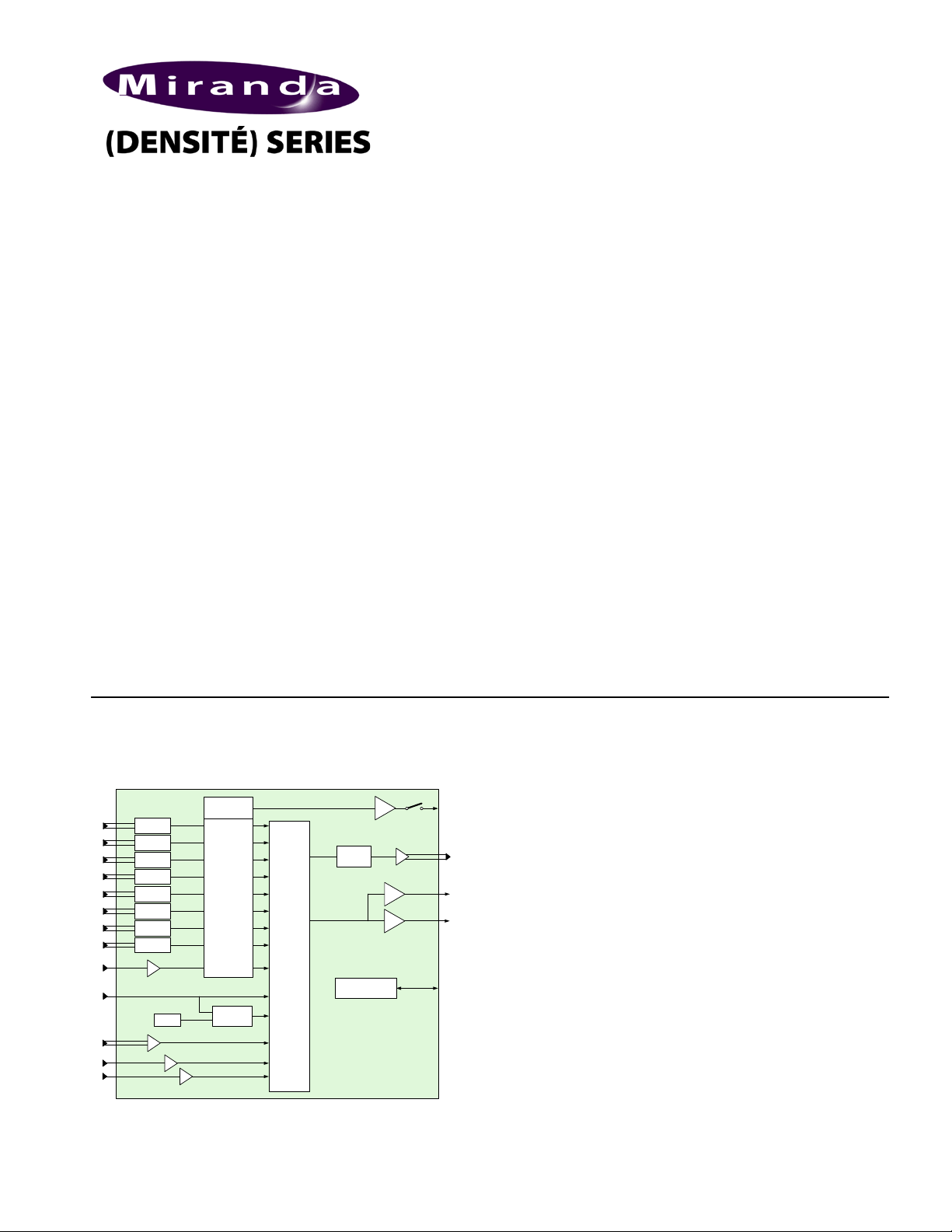
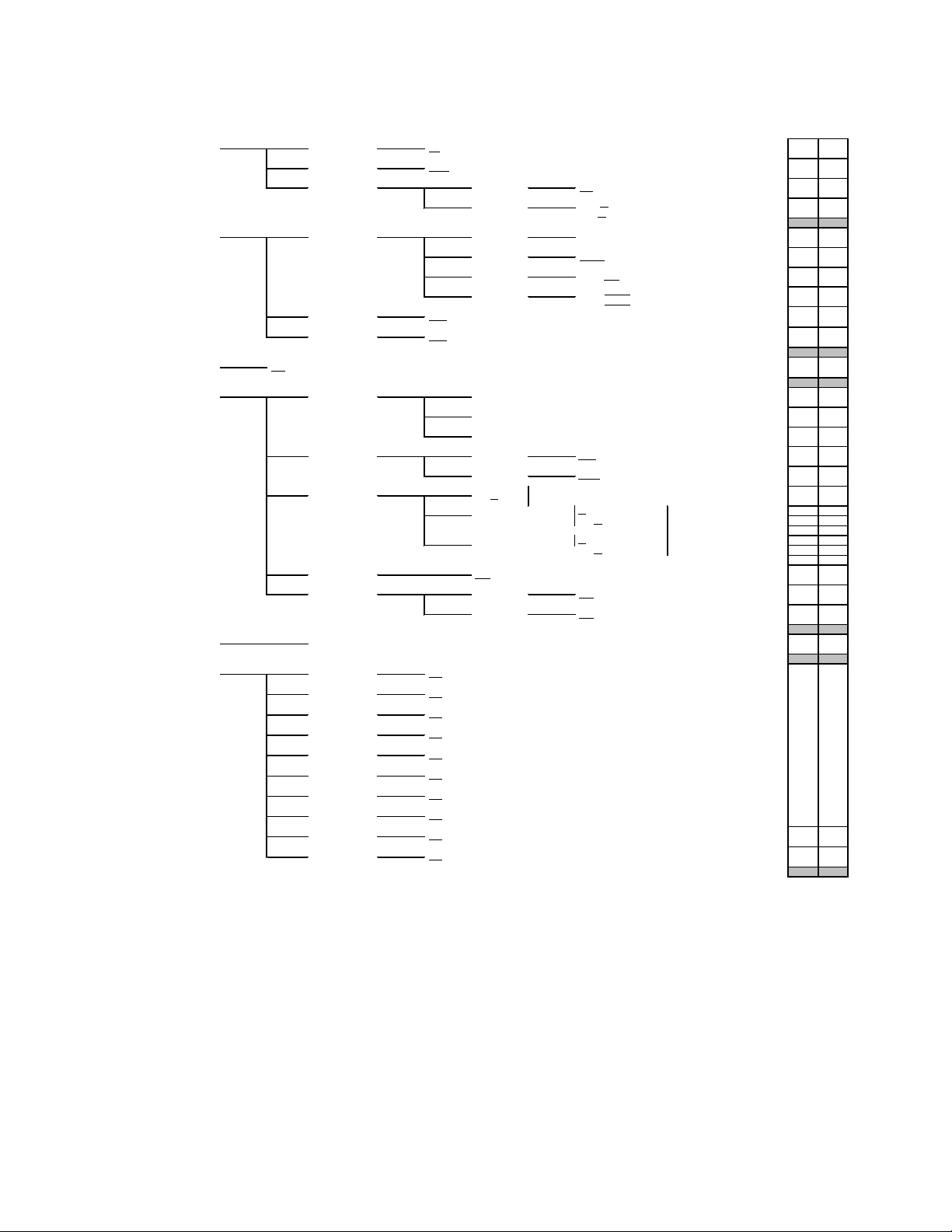
The AMX-1881 is a high-quality embedder which embeds
up to eight AES 24-bit 48 kHz digital audio signals into a
single HD/SD serial digital video signal. It includes audio
and video signal presence detection and reporting, and
local or remote configuration and control. A unique feature
is its ability to embed time code, a serial RS-422 data signal
and two GPI status signals into the video signal. The card
has built-in audio tone, time code and video color bar test
signals.
The AMX-1881 is designed for use in the DENSITÉ frame.
Video - Features
• Serial HD/SD-SDI input with automatic equalization for
up to 110/250 meters of cable.
• Automatic detection of video input format
• Automatic detection of input video loss and switchover
to local black for continuity of embedded audio.
Audio - Features
• Sample rate conversion for asynchronous AES inputs
• Audio input channel gain selectable from -96dB to
+12dB by 0.5dB steps
• Audio groups insertion/pass-through/delete
• Selectable audio delay of up to 3 frames in ½ frame
steps
• Left/Right channels swappable for each AES input
• Automatic mute on AES error
• Selectable routing of AES signals to audio groups
• Dolby-E compatible (48kHz synchronous)
• 24-bit digital audio embedding
• Monitor selector for Densité frame monitor switcher
(MSB)
Embedding Other Signals - Features
• Linear Time Code (LTC) embedding
• RS-422 serial data input for embedding as ANC data.
• Sampling of two GPI inputs for embedding as ANC
• AES inputs: either 110 Ω balanced or 75 Ω
data.
unbalanced, depending on rear panel in use
FUNCTIONAL BLOCK DIAGRAM SPECIFICATIONS
AMX-1881 Page 1 of 19
…..(continued)
SMPTE 292M / SMPTE 259M
Page 2
AMX-1881 HD/SD 8 AES Embedder
SPECIFICATIONS (cont’d)
LTC SIGNAL
Signal:
LTC per SMPTE 12M
Impedance:
< 10kΩ (bridging 600Ω) unbalanced
Level:
0.3 to 5Vp-p
VIDEO OUTPUT
Video Signal:
HD/SD-SDI
(Proprietary DID)
Return Loss:
>15 dB up to 1.485 GHz
Wideband Jitter:
As per SMPTE-259M-C and 292M
ANC SERIAL DATA INPUT
Signal:
RS-422
Level:
300 mVpp (min)
Rate:
38.400 or 115.200 bauds
ANC GENERAL PURPOSE INTERFACE (GPI) OUTPUT
Signal (2):
Contact closure (opto-isolated),
Level:
True = 0 to 0.8 V (max.)
Maximum input voltage = ±5.5 V
Rate:
DC to 250 Hz
PROCESSING PERFORMANCE
Signal Path:
10-bit video / 24-bit audio
Video Delay:
HD: 4.5 µs / SD: 11.5 µs
Audio Processing
Delay:
875 µs audio insertion delay ‡‡
Audio Delay:
Up to 3 video frames (1/2 frame steps)
LTC Delay:
Up to 3 video frames (one frame steps)
RS-422
max 500 µs ‡‡
GPI
Processing delay:
4 video lines ‡‡
Test Signals:
Video - color bars 100%
23:59:00:00
Power:
7 W
Note ‡‡: Applicable to combinations of this card and ADX-
1881.
List of supported formats:
1920 x 1080/23.98/PsF
Select
Status
Status LED
SELECT button
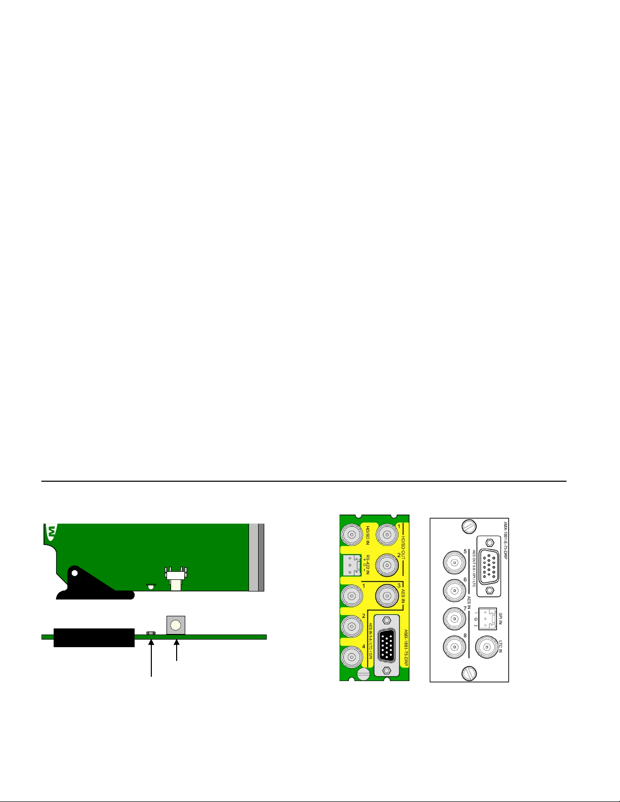
AMX-1881
AMX-1881Breakout
Panel
AMX-1881-75-DRP
Guide to Installation and Operation
AMX-1881 Front card edge (Note: female 15-pin connectors on both panels)
AMX-1881 Rear Connector Panels
(SMPTE 292M / SMPTE 259M)
Audio embedded per
SMPTE 299M / SMPTE 272M
LTC embedded as
ATC/DVITC
(SMPTE RP188/SMPTE 266M)
RS-422 and two GPIs embedded
as ANC data per SMPTE 291M
common ground
Processing delay:
Audio - 1 kHz tone (R steady, L pulsed)
-18dBFS (EBU R49, R68)
LTC – 10 second loop starting at
HD-SDI formats :
1920 x 1080/59.94/I
1920 x 1080/50/I
1920 x 1080/29.97/P
1920 x 1080/25/P
1920 x 1080/24/P
1920 x 1080/23.98/P
1920 x 1080/29.97/PsF
(detected as 1920 x 1080/59.94/I)
1920 x 1080/25/PsF
(detected as 1920 x 1080/50/I)
1920 x 1080/24/PsF
1280 x 720/59.94/P
1280 x 720/50/P
SD-SDI formats :
525
625
Page 2 of 19 AMX-1881
Page 3
REPORT
COLOR (F=flashing)
SERIAL
GPI G Y R FR
No errors
No signal
No rear
Test mode
A M X - 1 8 8 1
A LN O S I G N
INSTALLATION
Make sure the following items have been shipped with your
AMX-1881. If any of the following items are missing,
contact your distributor or Miranda Technologies Inc.
* AMX-1881 HD/SD 8 AES Embedder
* AMX-1881 -75-DRP rear panel
* AMX-1881 breakout panel
* Densité-ext-mount external mounting bracket (one per
frame)
The AMX-1881 and its associated rear connector panel
must be mounted in a DENSITÉ frame. It is not necessary
to switch off the frame’s power when installing or removing
the AMX-1881. See the DENSITÉ Frame manual for
detailed instructions for installing cards and their
associated rear panels.
OPERATION
Overview
The DENSITÉ frame incorporates a central controller card,
located in the center of the frame, which is equipped with
an LCD display and a control panel. The controller handles
error reporting and local and remote control for all cards
installed in the frame. The display and con trol pane l are
assigned to the card in the frame whose SELECT button
has been pushed.
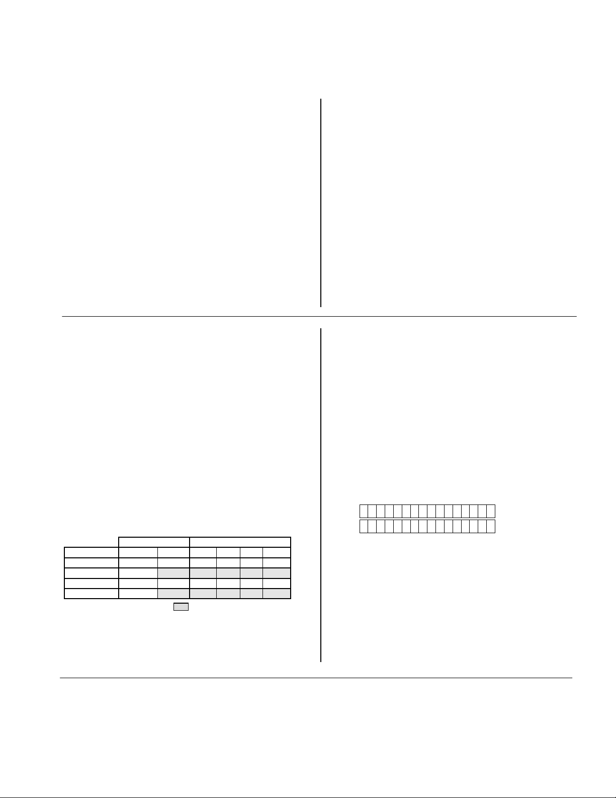
Status Monitor LED
The status monitor LED is located on the front card-edge of
the AMX-1881 module, and is visible through the front
access door of the DENSITÉ frame. This multi-c olor LED
indicates module status by color, and by flashing/steady
illumination, according to the following chart (which also
indicates fault reporting for this card on the DENSITÉ
frame’s serial and GPI interfaces).
: Factory default. User configurable
A “Flashing Yellow” Status LED indicates that the SELECT
button on the front panel has been pushed, and the
controller display and control panel are now assigned to
this card. The LED color assignments for some error
AMX-1881 HD/SD 8 AES Embedder
Guide to Installation and Operation
The AMX-1881 has multiple inputs and outputs, and
making space for all the necessary connectors at the rear
of the frame requires a double-width rear panel.
When a double–width rear panel has been installed, the
AMX-1881 must be installed in the right-most of the two
slots covered by the panel in order to mate with the panel’s
connectors. If it is placed in the wrong slot, the front panel
LED will flash red. Move the card to other slot for correct
operation. No damage will result to the card should this
occur.
In addition, the AMX-1881 requires an external mounting
bracket and breakout panel. The breakout panel is
connected to the rear panel via a multi-condu ctor cab le
fitted with two male connectors. The AMX-1881’s inputs
and outputs occupy both panels.
See the annex at the end of this manual for the
specification of the cable to interconnect the rear panel and
the breakout panel.
conditions can be reconfigured by the user (see the chart
and menu for details).
User Interface
Pushing the SELECT button will cause the on-card
STATUS LED to flash yellow, and the card identification
and the current status will be shown on the controller card’s
display. The STATUS LED will revert to it’s normal state
upon a second push of the button, or after a short delay.
The messages which may appear are shown in the top line
of the menu chart on page 4.
Example :
SELECT button pushed twice when there is no input
signal connected to the rear panel and the LED is
steady red:
Use the local control panel to access the detailed status
report shown in the STATUS menu on page 4.
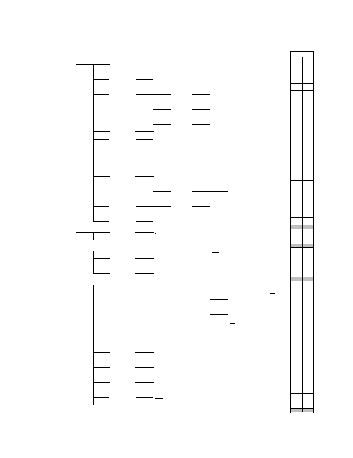
Operating Parameter Adjustment
The AMX-1881 has operating parameters which may be
adjusted at the controller card interface. After pressing the
SELECT button on the AMX-1881 card, use the keys on
the local control panel (described in the Controller card
manual) to step through the displayed menu and adjust the
parameters. The menus are shown below.
AMX-1881 Page 3 of 19
Page 4
AMX-1881 HD/SD 8 AES Embedder
HD SD
●
[ 20 BIT, 24 BIT
]
●
●
●
●●NONE/ PRESENT
AES IN
●
●
●
Applies to
●
●
●
●
NONE/ 1234
●
USER PRESET**
SAVE
INPUT S OURCE**
GROUP 1
LTC IN
●
AES IN 1
BITS
16 BIT / 20 BIT / 24 BIT / OTHER
●
AES IN 6
Same as AES IN 1
[ AES IN 1-2, A ES I N 3-4, A ES I N 5-6, A ES I N 7-8, PASS
, DELETE ]
AES IN 4
Same as AES IN 1
NONE / PRESENT
NONE / PRESENT
AES IN 5
Same as AES IN 1
PRESENCE
GROUP 4
STATUS
Same as AES IN 1
AUDIO GROUPS
NO REAR/ NO S IGNAL/ 720p50/ 720p60/ 720p59.94/ 1080p24/ 1080p24sF/ 1080p23. 98/ 1080p23.98sF/ 1080p25/ 1080i50/
1080p29.97/ 1080i59. 94/ 625/ 525
MODE
EMPHASIS
USE
ENCODING
NONE/ 1234
[ AES IN 1-2, A ES I N 3-4, A ES I N 5-6, A ES I N 7-8, PASS, DELETE ]
FOR MAT
4:3_0 / … / 16:9_5
N.I. / 2 CHA NNE L / 1 CHANNE L / P/S /
STEREO
N.I. / NONE / 50 / 15-us / J.17
Same as AES IN 1
[ 1, 2, 3, 4, 5 ]
[ 1
, 2, 3, 4, 5 ]
[ AES IN 1-2, A ES I N 3-4, A ES I N 5-6, A ES I N 7-8, PASS, DELETE ]
16:9_0 / … / 16:9_5
GROUP 3
AES IN 7
AES IN 8
LOAD
GROUP 2
AFD
CONSUMER / PROFESSIONA L
LINEAR PCM / NON P CM
Same as AES IN 1
DELAY
EMBED BITS
CONFIG AES**
SAM PLE RA T E CONV
PHASE INVERT
LEVEL
AES IN 3
Same as AES IN 1
AES IN 1
Same as AES IN 1
Same as AES IN 1
AES IN 4
[MUTE, -95.5 dB, ..., 0 dB
, ..., 12dB]
[MUTE, -95.5 dB, ..., 0 dB, ..., 12dB]
[ OFF, ON ]
[ OFF
, ON ]
AES IN 2
Same as AES IN 1
AES IN 3
Same as AES IN 1
[ OFF, ON ]
LEFT
RIGHT
LOCK
AES IN 2
Same as AES IN 1
LEFT
RIGHT
MUTE L&R
SWAP L&R
[ OFF
, ON ]
[ OFF, ON ]
[ OFF, AUTO ]
AES IN 5
Same as AES IN 1
AES IN 6
AES IN 7
AES IN 8
[ NONE, 0.5 FRAME, 1.0 FRAME, 1.5 FRAME, 2.0 FRAME, 2.5 FRAME, 3.0 FRAME ]
Same as AES IN 1
4:3_0 / … / 16:9_5
[ AES IN 1-2, A ES I N 3-4, A ES I N 5-6, A ES I N 7-8, PASS, DELETE ]
●
●
●
FOR MAT
VLI
PRESENCE
●
●
●
DOLB Y METADATA
NONE/P RESENT
●
●
●
●
●
●
●
Guide to Installation and Operation
AMX-1881 Menu
(continued)…..
Page 4 of 19 AMX-1881
Page 5
[ 10,…, 14, …, 20] for 525
[ 7, …, 16, …, 22 ] for 625
for 1080 format s
for 720 format s
[12, …, 19] ●
●
[12, …, 19] ●
●
GPI MODE**
●●[ EMBED, USER PRESET ]
●
●
●
●
●
●
●
●
●
●
●
●
●
●
●●●
●●●
●
●
●
●
AUT O BLACK**
[ OFF, ON ]
ANC SIGNALS**
RS-422
SAM PLED GPI 1
[ OFF, ON ]
DVITC
DUPLICATE
[ OFF, TONE ]
INSERTION TYPE
VALU E
SDI IN B LANK CTL
INSERTION LINE
VIDEO TEST
[ OFF, ON ]
AES IN 6
[ OFF, TONE ]
ASPECT RAT I O **
TC LOOP
[ OFF, ON ]
TEST**
AES IN 1
AES IN 3
[ OFF, TONE ]
AES IN 4
[ OFF, TONE ]
AES IN 5
[ LINE 9, LINE 10, …, LINE 25 ]
[ 38.4 Kb, 115 K b]
SAM PLED GPI 2
[ PASS, OV ERWRITE ]
[ PASS, OV ERWRITE ]
[ OFF, TONE ]
[ OFF, TONE ]
[ OFF, TONE ]
CONFI G LTC**
[ NO, YES ]
EMBED
LINE SELECT
MODE
[ OFF, TONE ]
AES IN 2
AES IN 7
AES IN 8
4:3 FORMAT
VLI
OFF
[ NONE, ODD, EVEN ]
[ LINE 9, LINE 10, …, LINE20 ]
METAD ATA LINE
BAUD RAT E
PARITY
DELAY
[ NONE, 1 FR AME, 2 FRAME, 3 FRAME ]
[OFF
, ON]
16:9 FO RMAT
[16:9_0, … , 16:9_5]
[9,10,11, …, 19]
for progres s iv e format only
[9,10,11, …, 19]
FIELD 2
VLI
for inter lac ed format only
AFD
[9,10,11, …, 19]
FIELD 1
[4:3_0, … , 4:3_5]
[OFF, O N]
[ OFF, SERIAL, METADATA ]
AFD
●
●
●
●
●
●
●
AUTO INSERTION
[OFF, O N]
●
●
●
(continued)…..
AMX-1881 HD/SD 8 AES Embedder
Guide to Installation and Operation
AMX-1881 Page 5 of 19
Page 6
AMX-1881 HD/SD 8 AES Embedder
** Press Select pushbutton to activate selection.
[ ] list of available parameter values.
Underlined values in the parameter value lists are the factory default values, and will be applied when factory default-restore is selected.
[ NONE
, GPI ]
●
●
ALARM REPORT
[ NONE
, GPI ]
[ NONE
, GPI ]
ALAR M LEVEL
[ GREEN
, Y E LLOW, RE D, FLASH RED ]
[ NONE
, GPI ]
NO AES8
ALAR M LEVEL
[ GREEN
, Y E LLOW, RE D, FLASH RED ]
●
●
NO AES5
ALAR M LEVEL
[ GREEN
, Y E LLOW, RE D, FLASH RED ]
ALARM REPORT
[ GREEN, YELLOW, RED
, FLASH RED ]
ALARM REPORT
[ NONE
, GPI ]
●
ALAR M LEVEL
[ GREEN
, Y E LLOW, RE D, FLASH RED ]
ALARM REPORT
[ NONE
, GPI ]
ALAR M LEVEL
[ GREEN
, Y E LLOW, RE D, FLASH RED ]
CONFI G A LARM**
ALAR M LEVEL
NO AES4
ALARM REPORT
ALARM REPORT
ALAR M LEVEL
FA CTORY DEFAULT**
[RESTORE]
NO SIGNAL
NO AES1
NO AES2
NO LTC IN
NO AES6
NO AES7
ALARM REPORT
ALARM REPORT
ALARM REPORT
ALAR M LEVEL
NO AES3
ALAR M LEVEL
ALAR M LEVEL
[ GREEN
, Y E LLOW, RE D, FLASH RED ]
[ NONE
, GPI ]
[ NONE
, GPI ]
[ GREEN
, Y E LLOW, RE D, FLASH RED ]
[ NONE
, GPI ]
[ GREEN
, Y E LLOW, RE D, FLASH RED ]
[ NONE
, GPI ]
[ GREEN
, Y E LLOW, RE D, FLASH RED ]
ALARM REPORT
TEST MODE
ALAR M LEVEL
ALARM REPORT
AMX-1881 :XXX
NO A FD PRESE NCE
NO VLI PRESENCE
ALARM REPORT
ALAR M LEVEL
VERSION
[ GREEN
, Y E LLOW, RE D, FLASH RED ]
[ NONE
, GPI ]
[ NONE
, GPI ]
ALARM REPORT
[ NONE
, GPI ]
ALAR M LEVEL
[ GREEN
, Y E LLOW, RE D, FLASH RED ]
[ GREEN
, Y E LLOW, RE D, FLASH RED ]
●
●
●
●
●
●
●
●
●
●
●
●
●
Guide to Installation and Operation
Page 6 of 19 AMX-1881
Page 7

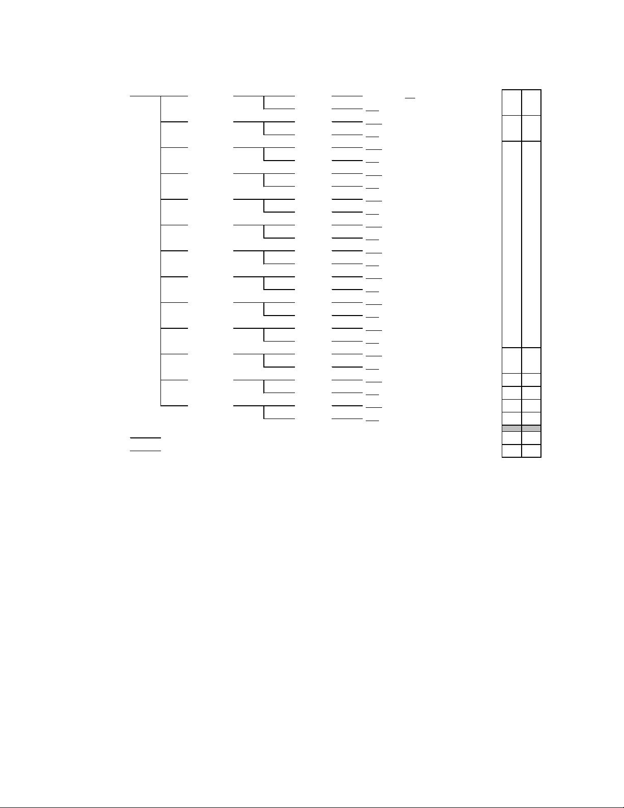
USER PRESET menu
LOAD: Selects which predefined parameter settings will be
used by loading a personalized profile.
SAVE: Saves the parameter settings in one of the five
possible user preset profiles.
INPUT SOURCE menu
GROUP1, GROUP2, GROUP3, GROUP4: Selects the
source of audio for the four embedded audio groups. AES
IN 1-2, AES IN 3-4, AES IN 5-6 & AES IN 7-8 select audio
from the AMX-1881 inputs. PASS leaves the incoming
embedded audio group intact, passing it through to the
HD/SD-SDI output. DEL deletes the incoming embedded
audio groups, leaving the HD/SD-SDI output without
embedded audio. Sample rate converters permit the AES
inputs to be synchronous or asynchronous.
Note 1 (525 format only): In order to allow the presen ce of
all four audio groups in the SD-SDI output, you must not
activate RS-422 serial data in the ANC Signals Menu.
Note 2: The standard for embedded audio specifies 48kHz
sampling, synchronous to video Sample rate converters
permit the input of asynchronous linear PCM audio, but
AES signals containing non-PCM audio must be synchronous 48kHz. Asynchronous inputs will affect the integrity
of channel status and user data, causing error flags to be
set that may be detected by downstream equipment.
CONFIG AES menu
AES IN 1, 2, 3, 4, 5, 6, 7, 8: Select MUTE: ON or OFF,
SWAP L&R: ON or OFF, or SAMPLE RATE CONV: OFF or
AUTO for each of the eight AES channels. In AUTO mode,
AES input detected as non-PCM audio will automatically
turn off the sample rate conversion process.
LEVEL: Sets the audio gain from -96 dB to +12 dB in 0.5
dB steps.
PHASE INVERT: When “on”, inverts the selected audio
channel phase.
DELAY: sets the delay of the AES signal as it passes
through the embedder, from NONE to 3 video frames in 0.5
frame steps.
EMBED BITS: Select the number of embedded bits in the
AES signal to either 20 or 24 bits.
CONFIG LTC menu
EMBED: Permits the user to embed LTC, as ATC into an
HD-SDI signal or as DVITC into a SD-SDI signal.
DELAY: LTC delay selectable between NONE and a
number of video frames (1 to 3).
DVITC (only in video SD mode) : LINE SELECT allows
user to choose the position of DVITC in the video signal.
DUPLICATE function allows the user to insert DVITC twice,
on two different video lines. To insert DVITC twice, set
DUPLICATE feature to ON.
AMX-1881 HD/SD 8 AES Embedder
Guide to Installation and Operation
ANC SIGNALS menu
RS-422: The incoming RS-422 serial data may be
embedded as ANC data. Select one of three modes:
• Select SERIAL to embed RS-422 in the horizontal
interval (HANC), overwriting previously-embedded
serial data
• Select METADATA to embed RS-422 in the vertical
interval (VANC), overwriting previously-embedded
metadata,
• Select OFF to leave RS-422 data untouched (no
insertion)
Note: In the 525 format, at least one of the four audio
groups must be set to DELETE in the Input Source menu
to allow RS-422 insertion.
Only works with signals at 38.400 or 115.200 Bauds with
accurate selection of BAUD RATE.
SAMPLED GPI 1, 2: The incoming GPI status data is
sampled and may be embedded as ANC data. Select
PASS to leave any already embedded GPI data untouched
(no insertion) or OVERWRITE, which embeds incoming
GPI data to the HD/SD-SDI signal while any existing
embedded GPI data is removed (NB: select EMBED in the
GPI Mode menu to enable this function).
AUTO BLACK menu
Turn AUTO BLACK ON or OFF. Auto Black replaces the
video input with a locally-generated video black in the
event of an input failure, to maintain audio embedding.
ASPECT RATIO menu
AFD MODE: Choose whether to PASS incoming AFD
flags, BLANK them, or INSERT new flags in their place.
AFD VALUE: Select the AFD flag to insert if selected in
AFD MODE. The available choices are format-dependent.
GPI MODE menu
Select EMBED to embed GPI data in the ANC, or USER
PRESET to use the GPI 1 and 2 inputs to select User
Presets 1 and 2 in operation.
TEST menu
AES IN 1, 2, …,8: User can enable (TONE) or disable
(OFF) a test tone (1 KHz, R-steady, L-pulsed, at –18dBFS)
on each of the eight AES cha n nels indiv idua lly.
COLOR BAR: User can enable (ON) or disable (OFF) color
bars on the video output.
TC LOOP: User can enable a test loop (10 second loop
starting at 23:59:00:00) that is inserted into the video as
ATC (HD-SDI video) or DVITC (SD-SDI video).
CONFIG ALARM menu
The user can configure the status LED presentation
(ALARM LEVEL) and fault reporting (NONE or GPI) for
some of the fault conditions of the AMX-1881. Those not
listed in the menu are factory-set and cannot be usermodified.
AMX-1881 Page 7 of 19
Page 8

AMX-1881 HD/SD 8 AES Embedder
iControl Interface
Status bar
Audio
Guide to Installation and Operation
FACTORY DEFAULT menu
Select RESTORE to reset all of the menu-adjustable
parameters to a factory-preset state (indicated in the menu
by an underline in the list of available choices)
The AMX-1881 can be operated using Miranda’s iControl
system. This manual describes and explains the control
panel associated with the AMX-1881. Please consult the
iControl User’s Guide for information about setting up and
operating iControl.
In Control Navigator or iControl Websites, double-click on
the AMX-1881 icon to open the control panel.
Input Error: allows the user to turn on and off the auto
black feature. A complete description of the Input Error
panel begins on page 12.
Test: gives the option to insert test signal s. A compl ete
description of the Test panel begins on page 12.
Factory: Allows the user to reset the options to the default
factory-preset settings. A com plete description of the
Factory panel begins on page 12.
Alarm Config: Opens a new window where the on-board
alarms of this AMX-1881 can be configured. See Annex 2
beginning on page 15 for a complete description.
Info: shows information about the AMX-1881 and allows
entry of some data. A complete description of the Info
panel begins on page 12.
User Presets: Allows the creation of user profiles for a
personalised configuration of the AMX-1881. A complete
description of the User presets begins on page 13.
Profiles: Opens a new window allowing the user to copy
configuration data from this AMX-1881 to others accessible
via iControl. See Annex 3 beginning on page 17 for details.
Status Bar: located at the top of the panel, it provides
status icons for several key items and text messages
explaining the detected errors. A complete description of
the Status bar is given on this page.
Select the following control panels by clicking on their
name at the left side of the panel:
Audio: provides controls for processing and embedding
audio signals. A complete description of the Audio panel
begins on this page.
Metadata : gives access to the controls for LTC, RS-422
and GPI status data embedding in an HD/SD SDI signal. A
full description of the Metadata panel begins on page 10.
Aspect Ratio: gives access to control of Active Format
Descriptor (AFD) and VLI data in the data stream. The
panel is described beginning on page 10.
The status bar provides a continuous update of the status
of the AMX-1881. The status bar includes three sections:
Header
Icons
Message area
The header gives the product’s name, and identifies the
slot in which it is installed in its Densité frame. At the left is
a status icon whose color shows the overall status of the
AMX-1881 (see Annex 2 for more information):
Green = OK
Yellow = warning
Red = error
The 3 icons monitor specific aspects of the AMX-1881’s
operations. Move the cursor over an icon to see its current
status in the message area below the icons. If there is an
error status, the message will appear automatically
The first icon shows whether the remote control of this
AMX-1881 device is enabled or not.
The second icon shows the input status. Move the cursor
over the icon to display the input signal format.
The third icon indicates if audio or video test signals are
active.
The audio tab shows the audio groups detected and
provides resources for managing the audio processing of
the AMX-1881.
Page 8 of 19 AMX-1881
Page 9

Group detected: indicates embedded audio groups in the
AMX-1881 SDI input by turning green.
AES detected: indicates AES audio on the indicated AMX1881 AES input by turning green.
AMX-1881 HD/SD 8 AES Embedder
Guide to Installation and Operation
The Embedding tab specifies the content of the AES
groups embedded in the output signal. Each group can be
composed of a pair of AES inputs (AES1-2 , AES3-4,
AES5-6, or AES7-8). If the video input already contains an
embedded audio group, it can either be allowed to pass
through directly without modifications (PASS) or it can be
deleted (DELETE). The SD Embed bits is fixed at 24 bits
for HD. For SD signals, the options are 20 or 24 bits
To configure the AES digital audio signals, acces s the
AES1-2 through AES7-8 tabs. There are two sliders (left
and right for stereo sound) available for each AES to set
the level from -96 dB to +12 dB in steps of 0.5 dB. To invert
the selected audio channel phase, check the phase invert
boxes. The lock option locks bot h chan nel level sli der s
together, so that moving one slider moves the other one as
well. The mute option mutes both audio channels
completely. The swap option interchanges the right and
the left audio channels. The sample rate converter can be
set to either auto or off. While in auto mode, the sample
rate conversion process is automatically turned off upon
detection of non-pcm channel status.
The Delay tab allows the user to set the delay of the AES
audio as it passes through the embedder. The delay is
selectable between none, and a number of video frames (0
to 3 frames in 0.5 frames steps).
The status tab monitors some of the information carried in
the AES inputs channel status..
The Bits status monitors the audio samples word length (in
bits). The possible values are 16 bits, 20 bits, 24 bits or
other. If the information is not available, it will show as N/I.
The Mode status monitors the channel mode. The pos sib le
values are two channels (Two ch), one channel (One ch),
primary or secondary (Pri/Sec), Stereo or Other. If not
indicated, it will show as N/I.
The Emph status monitors the audio channel emphasis.
The possible values are n one, 50/15 µs (CD type) and
J.17. If not indicated, it will show as N/I.
The Use status monitors the use of channel status block.
The possible values are either professional (PRO) or
consumer (CONS).
The Encd status monitors the audio channel encoding
type. The possible values are PCM or NPCM (non PCM).
AMX-1881 Page 9 of 19
Page 10

AMX-1881 HD/SD 8 AES Embedder
Metadata
User Preset: the two GPI
the two GPI data sets.
Aspect Ratio
A
D
Guide to Installation and Operation
The Metadata tab offers setting options for 3 types of input
signals: LTC, RS422 and GPI.
The LTC tab allows the embedding of an LTC signal as
ATC into an HD-SDI or as DVITC into an SD-SDI signal.
B
C
A: the presence icon shows if an LTC signal is detected by
turning green.
B: the insertion can be toggled to OFF or ON, to disable
or activate the embedding of the LTC signal into the HD/SD
SDI signal.
ATC packets are inserted as follows:
• 1080i – lines 9 & 10 in field 1; line 8 in field 2
• 720p – lines 9 & 10
C: the delay option allows correction of lipsync problems
by adding up to 3 frames of delay.
D: the DVITC menu has two parameters, Insert line and
duplicate. The insert line option allows the user to choose
the position of the DVITC in the video signal, while the
duplicate option inserts a second DVITC packet on the
video line following the one chosen by the user.
The RS-422 tab allows the embedding of RS-422 serial
data as ANC data in the HS/SD SDI signal.
METADATA (HD only): embeds the RS-422 data in the
vertical interval (VANC).
• The Metadata Line pulldown becomes active, allowing
selection of the line to write the data (9-20)
• Data in the selected line is overwritten
• Data in other lines is unchanged.
The GPI tab gives access to two different functions,
selected by the Mode pulldown:
inputs are used to select
User Presets 1 and 2
(see User Presets on
page 14)
Embed: allows the
embedding of sampled
GPI status data as ANC
data. Select either Pass
(leaving the already
embedded data
untouched) or Overwrite
(embedding the new GPI
data in the HD/SD-SDI
signal, overwriting the
previous data) for each of
The Active Format Descriptor (AFD) conveys information
about the “protected “area inside a picture, the aspect ratio,
and the preferred presentation of the image. The AFD
consists of the Aspect Ratio of the display monitor for
which the signal is intended, and a code indicating the
nature of the protected area and preferred display.
Mode:
OFF will leave any embedded RS-422 data untouched,
SERIAL: (HD and SD): embeds the RS-422 data in the
horizontal blanking (HANC), overwriting previouslyembedded serial data. The Baud Rate and Parity pulldowns are activated:
• Baud Rate: supports 38.4 and 115 Kb
• Parity: none, even or odd
Note: in 525 format, to activate the Serial mode, at least
one of the four audio groups must be set to “Delete”
Page 10 of 19 AMX-1881
Page 11

The Input aspect ratio section indicates the presence of
AFD and VLI flags in the incoming video via status icon s
(green if flags are present; gray otherwise), and displays an
interpretive graphic that incorporates the flag code.
The Output Aspect Ratio section provides controls for
insertion of aspect ratio signalling in the output data
stream.
Use the radio buttons in the Insertion box to select AFD,
VLI or OFF as the insertion mode.
• Incoming aspect ratio data of the selected type will
be deleted, and replaced by a specified flag,
designated at the bottom of the panel.
• If the AUTO box is checked, the AMX-1881 will pass
any incoming flags of the sele cted ty pe unchanged,
but when no flag is detected on the input, it will
insert a specified flag into the output data stream.
Any incoming aspect ratio signalling data that is not
selected for overwriting via the Insertion controls may be
either blanked or passed, using the radio buttons shown:
• PASS: pass any incoming
flags unchanged
• BLANK: delete any incoming
flags
Incoming data that is selected for overwriting via insertion
will be gray – e.g. AFD in the figure.
• INSERT: insert an AFD flag in the output, overwriting
any incoming flags
• AUTO: Pass any incoming flags unchanged, but when
no flag is detected on the input, insert a specified flag
into the output data stream.
AMX-1881 HD/SD 8 AES Embedder
Guide to Installation and Operation
The INSERT and AUTO modes require the user to select a
flag to insert. The graphic shows the code for the current
selection, while the Change button opens a window
showing all available flags.
AMX-1881 Page 11 of 19
Scroll down if necessary to see all possible flag options.
Click on one to select it, and click Apply at the bottom of
the window to confirm the selection.
Use the AFD Field 1 and AFD Field 2 pulldowns to select
the line on which AFD information will be inserted on the
two fields.
NOTE: If incoming flags are found on a line after the
selected insertion line, the AMX-1881 will not be able to
change its insertion decision in the AUTO mode until the
next field/frame, and will therefore not be field/frame
accurate.
Page 12

AMX-1881 HD/SD 8 AES Embedder
Input error
Test
Factory
Alarm Config
Info
Enables a test pattern at
SD-SDI video. Note 2.
Guide to Installation and Operation
The AFD presets button allows the user to save
commonly-used selections under descr iptiv e nam es,
making it easy to recall and load selections for specific
situations. The name of the current preset is displayed.
• Type a name in the Preset Name box and click Save
to save the current Mode and Aspect Ratio settings
under this name. The newly-saved layout is also
loaded (see below) when the save command is
selected, so its name will be shown in the Current
Preset box beside the AFD Presets button in the
Output AFD window.
• Click a name in the list to select it, and then click Load
to configure the AMX-1881 to send that AFD flag.
To see the mode and value saved in any Preset, click the
Info button to the right of its name to open the Parameters
window:
In the event of an input failure, activating the auto black
feature will replace the video input with a locally generated
video black in order to maintain audio embedding.
The test menu allows the user to enable test signals on the
AES and video outputs for troubleshooting purposes.
Notes:
1. If an AES checkbox is enabled, the corresponding
AES channel should be used as a source for
embedding in an audio group. Set this in the Audio
Insert section of t he Audio panel’s Embedding tab.
(See page 9)
2. LTC timecode insertion should be set to ON in the
Metadata / LTC panel in order for the timecode to be
embedded. (See page 10)
Clicking the Load Factory button will restore all of the
adjustable parameters to a factory-preset state. Those
preset settings are indicated by an underline in the AMX-
1881 menu on pages 4 to 6 of this manual.
See Annex 2 on page 15 for details.
The Info tab provides information about the AMX-1881,
and provides some data entry options.
Label and Short label: type a label and a short label for
this device in the appropriate data entry boxes.
Source ID: enter the source ID
The details button gives additi onal information about the
device. The manufacturing process, firmware version,
service version and panel version can be found here.
the video output.
Enables a test tone (1
KHz, R-steady, L-pulsed,
at-18 dBFS) in each of
the eight AES channels
individually. Note 1.
Enables an output test
loop (10 second loop
starting at 23:59:00:00)
in the video as ATC into
HD-SDI or as DVITC in
Page 12 of 19 AMX-1881
Page 13

User presets
Profiles
The advanced button shows the long ID of the device. The
Miranda Long ID is the address of this AMX-1881 in the
iControl network.
Click the remote system administration button to open
the “joining locators: AMX-1881” window, which lists
remote lookup services to which this AMX-1881 is
registered, and allows new ones to be added.
AMX-1881 HD/SD 8 AES Embedder
Guide to Installation and Operation
.
Select any one of the five presets using the pull-down list.
The name of the currently-selected User Preset is shown
on the name bar.
• Click Load to load the contents of the selected User
Preset into the AMX-1881. All parameter settings and
values will be replaced by the contents of the selected
User Preset.
• Click Save to store the current parameter settings and
values from the AMX-1881 into the selected User
Preset. The existing contents of the preset will be
overwritten.
Note that you can use GPI inputs 1 and 2 to select and
load Presets 1 and 2 if you have chosen the User Preset
mode in the GPI tab in the Metadata window.
The AMX-1881 has memory registers which can hold up to
5 user-defined parameter settings
See Annex 3 on page 17 for details.
AMX-1881 Page 13 of 19
Page 14

AMX-1881 HD/SD 8 AES Embedder
Guide to Installation and Operation
ANNEX 1 – Connecting Cable Specification
This cable joins the AMX-1881 rear panel to the AMX-1881 breakout panel
Page 14 of 19 AMX-1881
Page 15

AMX-1881 HD/SD 8 AES Embedder
Guide to Installation and Operation
ANNEX 2 – Alarm Configuration
Click on the Alarm Config button on the left-hand
side of the iControl panel to open this panel in new
window.
This panel allows the alarm reporting of the AMX1881 to be configured.
The panel is organized in columns.
Status/Name
This contains an expandable tree listing all the
alarms reported by this AMX-1881 card.
• Each alarm name includes an icon that shows
its current status
• Some alarms may be text-only and the alarm
status is shown in the name and not by a status
icon,
e.g.
The Overall alarm and GSM contr ibution columns
contain pulldown lists that allow the level of
contribution of each individual alarm to the alarm
named in the column heading to be set.
Levels associated with these alarms
The pulldown lists may contain some or all of the following options:
The alarm makes no contribution (black)
The alarm is of minor importance (yellow)
The alarm is of major importance (orange)
The alarm is of critical importance (red)
The alarm exists but has no effect (used for text and composite alarms)
Shortcut: if you click Set All in one of the columns beside a major heading in the Status/Name column, you will open a
pulldown that lets you assign a level to all alarms in that section of the column simultaneously.
• Overall Alarm
This column allows configuration of the contribution of each individual alarm to the Overall Alarm associated with this card.
The Overall Alarm is shown in the upper left corner of the iControl panel, and also appears at the bottom of the Status/Name
column.
AMX-1881 Page 15 of 19
Page 16

AMX-1881 HD/SD 8 AES Embedder
Guide to Installation and Operation
• GSM Contribution
This column allows configuration of the contribution of each individual alarm to the GSM Alarm Status associated with this
card. GSM is a dynamic register of all iControl system alarms, and is also an alarm provider for external applications. The
possible values for this contribution are related to the Overall alarm contribution:
• If the Overall alarm contribution is selected as Disabled, the GSM alarm contribution can be set to any available value
• If the Overall alarm contribution is selected as any level other than disabled, the GSM contribution is forced to follow the
Overall Alarm.
Log Events
iControl maintains a log of alarm events associated with the card. The log is useful for troubleshooting and identifying event
sequences. Click in the checkbox to enable logging of alarm events for each individual alarm.
At the bottom of the window are several other controls:
Overall Alarm and GSM Contribution follow card LED
Click in the checkbox to force the Overall alarm and GSM
contribution to be identical to the Card LED status
• All Overall alarms and GSM contributions for which there is a
Card LED alarm will be forced to match the Card LED alarm
• All Overall Alarms and GSM contributions for which there is
no Card LED alarm will be forced to Disabled
A warning box will open allowing you to confirm the action, since it
will result in changes to the configuration and there is no undo
function.
Copy to other cards
Click this button to open a panel that allows the alarm configuration
set for this card to be copied into another AMX-1881 card.
• Select one or more destination cards from the list in the
window by clicking in the checkboxes, or all of them by
clicking in the All checkbox
• Note that when you do a Copy Profile for this card (see
Annex 3), the alarm configuration is copied along with all the
other settings.
Get alarm keys
Click this button to open a save dialog where you can save a file
containing a list of all alarms on this card and their current values,
along with an Alarm Key for each. The alarm keys are useful for
system integration and troubleshooting.
• The file is saved in Excel.csv format
OK, Apply, Cancel
• OK accepts the settings and closes the window once the
card confirms that there are no errors.
• Apply accepts the settings, but leaves the window open
• Cancel closes the window without applying any changes, and leaves the previous settings intact
Page 16 of 19 AMX-1881
Page 17

AMX-1881 HD/SD 8 AES Embedder
Guide to Installation and Operation
Annex 3 – Profile Copy
This panel provides the option to save and recover the entire card configuration (including user presets if desired) on an
external disk, or to copy it to another AMX-1881 card.
Click on Profiles to open the Profile Copy window.
Copy Profile From:
This line shows this AMX-1881 card, and identifies it by App server, Densité frame and slot number, card type and firmware
version.
The Profile column has a pulldown that allows you to select which profiles you will work with, and gives these choices:
• Current, User1, User2, User3, User4, User5
The Select column includes a checkbox, preselected as checked, to confirm that you want to work with the current card.
Save Profile to Disk…
Click this button to open a Save dialog allowing you to specify a file
name and location to which the selected profiles for this card will be
saved.
Hint - It is a good idea to create a folder for these files, because
they are not explicitly identified as AMX-1881 profiles, and will be
difficult to find and identify if not clearly named and conveniently
located.
• Click the save button once the name and location have been
identified in the Save box
• If the file is saved correctly, the Transfer Status box on the
right of the Copy profile from line will indicate Succeeded
against a green background
• If the file was not saved for some reason, the Transfer
Status box to the right of the Copy profile from line will
indicate Failed against a red background
AMX-1881 Page 17 of 19
Page 18

AMX-1881 HD/SD 8 AES Embedder
Guide to Installation and Operation
Restore profile from disk…
Click this button to open an Open dialog box within which you can
locate and select a valid AMX-1881 profile file.
• Click Open to read the contents of the file and to reconfigure
this AMX-1881’s profiles according to its contents
• While the reconfiguration is in progress, the Transfer Status
box on the right of the Copy profile from line will indicate
Working against a yellow background
• When the reconfiguration is complete, the Transfer Status
box on the right of the Copy profile from line will indicate
Succeeded against a green background
Note: There is no need to select a profile using the Profile
pulldown (e.g. current, User1, etc.) when restoring a profile from
disk, because the profile selection is stored within the file.
Copy profile to section
This line shows other AMX-1881 cards that are available on the iControl network, each identified by App server, Densité frame
and slot number, card type and firmware version.
The Profile column shows the same information as is shown for the current card in the Copy profile from line, i.e.
• Current, User1, User2, User3, User4, User5
The Select column includes a checkbox to identify which AMX-1881 cards you wish to copy profiles into from the current card.
• For convenience, a Select all checkbox is provided in the column header
• Source and destination cards must have the same firmware version for the copy profile to work
Click Copy to copy the selected profiles from this card into the selected other AMX-1881 cards
• While the profile copy operation is in progress, the Transfer Status box on the right of the Copy profile to line will indicate
Working against a yellow background
• When the profile copy operation is complete, the Transfer Status box on the right of the Copy profile to line will indicate
Succeeded against a green background
Page 18 of 19 AMX-1881
Page 19

AMX-1881 HD/SD 8 AES Embedder
China
France (only)
Guide to Installation and Operation
Electromagnetic Compatibility
This equipment has been tested for verification of compliance with FCC Part 15, Subpart B requirements
for Class A digital devices.
NOTE: This equipment has been tested and found to comply with the limits for a Class A digital device,
pursuant to part 15 of the FCC Rules. These limits are designed to provide reasonable protection against
harmful interference when the equipment is operated in a commercial environment. This equipment generates,
uses, and can radiate radio frequency energy and, if not installed and used in accordance with the instruction
manual, may cause harmful interference to radio communications. Operation of this equipment in a residential
area is likely to cause harmful interference in which case the user will be required to correct the interference at
his own expense.
This equipment has been tested and found to comply with the requirements of the EMC directive
2004/108/CE:
• EN 55022 Class A radiated and conducted emissions
• ENV 50204
• EN 61000-3-2 Harmonic current injection
• EN 61000-3-3 Limitation of voltage changes, voltage fluctuations and flicker
• EN 61000-4-2 Electrostatic disc harge immunity
• EN 61000-4-3 Radiated electromagnetic field immunity – radio frequencies
• EN 61000-4-4 Electrical fast transient immunity
• EN 61000-4-5 Surge immunity
• EN 61000-4-6 Conducted emissions immunity
• EN 61000-4-11 Voltage dips, short interruptions and volta ge var iat ions immunity
How to contact us:
For technical assistance, please contact the Miranda Technical support centre nearest you:
Americas
Telephone:
+1-800-224-7882
e-mail:
techsupp@miranda.com
Asia
Telephone:
+852-2539-6987
e-mail:
asiatech@miranda.com
Telephone:
+86-10-5873-1814
e-mail:
asiatech@miranda.com
Visit our web site at www.miranda.com
Europe, Middle East, Africa, UK
Telephone:
+44 (0) 1491 820222
e-mail:
eurotech@miranda.com
Telephone:
+33 (0) 1 55 86 87 88
e-mail:
eurotech@miranda.com
AMX-1881 Page 19 of 19
 Loading...