

Page 1

ADX-1901
3G/HD/SD 8 Channel Analog Audio De-Embedder
Guide to Installation and Operation
M3005-9900-101
2015-04-29
Page 2

GUIDE TO INSTALLATION AND OPERATION
Electromagnetic Compatibility
This equipment has been tested for verification of compliance with FCC Part 15, Subpart B requirements for
Class A digital devices.
NOTE: This equipment has been tested and found to comply with the limits for a Class A digital device, pursuant to
part 15 of the FCC Rules. These limits are designed to provide reasonable protection against harmful interference
when the equipment is operated in a commercial environment. This equipment generates, uses, and can radiate
radio frequency energy and, if not installed and used in accordance with the instruction manual, may cause harmful
interference to radio communications. Operation of this equipment in a residential area is likely to cause harmful
interference in which case the user will be required to correct the interference at his own expense.
This equipment has been tested and found to comply with the requirements of the EMC directive
2004/108/CE:
• EN 55022 Class A radiated and conducted emissions
• ENV 50204 Radiated EMF Immunit y – RF 900 MHz Pulsed
• EN 61000-3-2 Harmonic current emission limits
• EN 61000-3-3 Voltage fluctuations and flicker limitations
• EN 61000-4-2 Electrostatic disc harge immunity
• EN 61000-4-3 Radiated electromagnetic field immunity – radio frequencies
• EN 61000-4-4 Electrical fast transient immunity
• EN 61000-4-5 Surge transient im munity
• EN 61000-4-11 Voltage-dips, short-interruption and voltage variation immunity
ADX-1901
Page 3

GUIDE TO INSTALLATION AND OPERATION
Table of Contents
1 ADX-1901 3G /HD/SD 8 Channel Analog Audio De- Embedder .............................................. 1
1.1 Introduction ......................................................................................................................................... 1
1.2 Features .............................................................................................................................................. 1
1.3 Functional Block Diagram ................................................................................................................... 2
1.4 Front Card-edge Interface ................................................................................................................... 2
2 Installation ................................................................................................................................ 3
2.1 Installation of Rear Connector Panels ................................................................................................ 3
2.2 ADX-1901 Card Installation ................................................................................................................ 4
2.3 Installation of the Optical Interface (option) ........................................................................................ 4
2.4 Rear Panels and Connectors .............................................................................................................. 5
2.4.1 Images of Rear Panel Connectors ......................................................................................... 5
2.4.2 Summary of rear panel connections ...................................................................................... 5
2.4.3 Details of rear panel connections .......................................................................................... 6
3 User Interface ........................................................................................................................... 8
3.1 Control options .................................................................................................................................... 8
3.2 Card-Edge Status LED ....................................................................................................................... 8
4 Local control using the Densité frame control panel ............................................................ 9
4.1 Overview ............................................................................................................................................. 9
4.2 Menu for local control ........................................................................................................................ 10
5 Remote control using iControl .............................................................................................. 11
5.1 The iControl graphic interface window .............................................................................................. 11
5.2 Video Input/Output panel .................................................................................................................. 13
5.2.1 Video Input/Output panel (no fiber support) ......................................................................... 14
5.2.2 Video Input/Output panel with fiber support ......................................................................... 14
5.3 Metadata panel ................................................................................................................................. 15
5.3.1 TC-GPI tab ........................................................................................................................... 15
5.3.2 Audio tab .............................................................................................................................. 16
5.4 Audio Inputs panel ............................................................................................................................ 17
5.4.1 CH 1-4, 5-8, 9-12, 13-16 tabs .............................................................................................. 17
5.4.2 The Status tab: ..................................................................................................................... 18
5.5 Audio Output panel ........................................................................................................................... 18
5.5.1 1-2, 3-4, 5-6, 7-8 tabs .......................................................................................................... 18
5.5.2 Config tab ............................................................................................................................. 19
5.6 Audio Programs panel ...................................................................................................................... 20
5.7 Downmix panel.................................................................................................................................. 21
5.8 Loudness Panel ................................................................................................................................ 22
5.8.1 Loudness | Config panel ...................................................................................................... 22
5.8.2 Loudness | PGM panel ........................................................................................................ 23
5.9 Alarms panel ..................................................................................................................................... 24
5.9.1 Alarms – Video pan el ........................................................................................................... 24
5.9.2 Alarms – Metadata panel ..................................................................................................... 25
5.9.3 Alarms – Audio pan el ........................................................................................................... 26
5.10 Monitoring panel................................................................................................................................ 29
5.10.1 RALM Connections tab ........................................................................................................ 29
ADX-1901
Page 4

GUIDE TO INSTALLATION AND OPERATION
Meter Ballistics Config tab .................................................................................................... 29
5.10.2
5.11 Test panel .......................................................................................................................................... 30
5.12 Factory/Presets panel ........................................................................................................................ 31
5.13 Alarm Config panel ............................................................................................................................ 33
5.14 Info panel ........................................................................................................................................... 36
6 Specifications ........................................................................................................................ 38
7 Grass Valley Technical Support ........................................................................................... 40
ANNEX 1 – ADX-1901 Local User Interface ................................................................................ 41
ANNEX 2 – Installing the Optical Interface ................................................................................ 42
ANNEX 3 - Loudness Logging and the Miranda Audio Loudness Analyzer ............................ 44
ADX-1901
Page 5

GUIDE TO INSTALLATION AND OPERATION
1 ADX-1901 3G/HD/SD 8 Channel Analog Audio De- Embedder
1.1 Introduction
The ADX-1901 is an advanced, high quality 24-bit 48 KHz analog audio de-embedder designed to extract eight
analog audio signals from a 3G/HD/SD video s ignal. The ADX-1901 can process the 8 audio de-embedded channels
with functions including level, channel shuffling and mixing.
The loudness meas urement features allows the measurem ent and logging of up to 8 audio program s with iControl
Loudness Monitoring sof tware to analyze and report compliance w ith respect to various loudness legislation around
the world. Furthermore, a delay of up to 2.7 seconds can be programmed independently per de-embedded audio
channel to provide lip sync correction.
The ADX-1901 can de-embed Ancillary Time Code (ATC) in 3Gbps/HD, or DVITC in SD, to generate Linear Time
Code (LTC). Up to two GPIO can be generated by extracting GPI events from the Time Code user bits in transport
applications. Audio Metadata extraction from the VANC can be streamed to an external RS-422 output.
The ADX-1901 is des igned for the Densité 2 frame, but will be compatible with the Densité 3 f rame with the metal
extender. Multiple rear connector panels are available according to your application needs and the chassis type used.
A fiber input/output cartridge is offered as an option on some rear modules. Once the cartridge is installed, the input or
outputs are selectable through the control interface.
1.2 Features
Audio
• 8 analog audio outputs
• Audio silence output on loss of video input.
• Full audio shuffling and mixing on a channel output basis
• Individually adjustable audio output levels
• Audio 5.1 surround downmix to Lo/Ro
• Audio delay adjustments of up to 2.7 seconds to compensate for lip sync issues
• Built in test generator (audio).
• Monitoring and reporting of audio output Max/Min Level, Silence and Phase.
• Loudness measurement of up to 8 audio programs and logging with iControl Loudness Monitoring software
• Loudness compliant to EBU R128, ATSC A/8 5:2 013 and ARIB TR-B32 (ITU-R BS.1770-3))
Video
• 3Gbps/HD/SD input with automatic equalization
• Supports 3Gbps level A (mapping 1) and level B
• Automatic detection of video input format
• Optional optical fiber SFP cartridge
• Black Detection monitoring
Metadata
• Linear Time Code (LTC) output translated from DVITC (SD) or ATC (3Gbps/HD)
• 2 GPI data output signals reconstructed from ANC TC user bits.
• RS-422 serial data output to carry Audio Metadata (SMPTE 2020-A) from the VANC.
ADX-1901 | 1
Page 6
GUIDE TO INSTALLATION AND OPERATION
Select
Status
ADX-1901
Status LED
Select Button
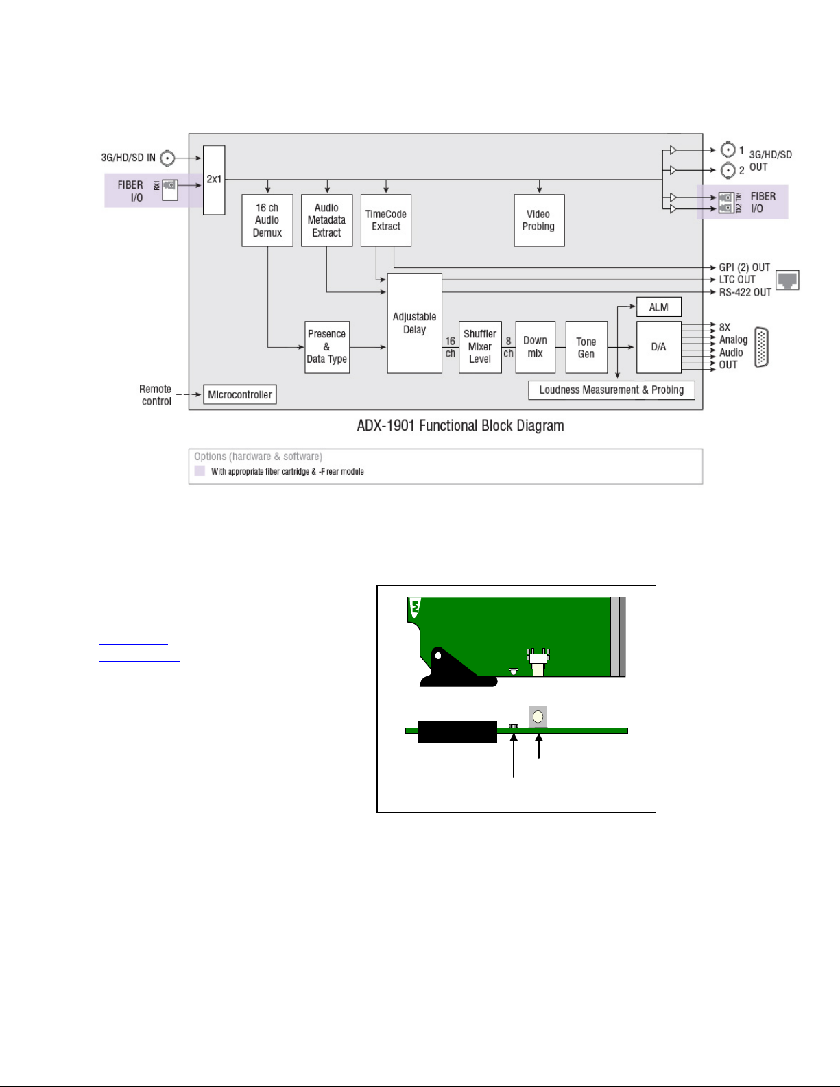
1.3 Functional Block Diagram
Figure 1.1 ADX-1901 Functional Block Diagram
1.4 Front Card-edge Interface
The front card-edge of the ADX-1901 incorporates
two elements:
• Status LED (see section 3.2
• Select Button (see section 4)
Figure 1.2 Front card-edge layout
)
2 | ADX-1901
Page 7
GUIDE TO INSTALLATION AND OPERATION
2 Installation
2.1 Installation of Rear Connector Panels
Grass Valley Densité-series cards are each associated with a rear connector panel, which must be installed in the
Densité frame before the card can be inserted.
The ADX-1901 card is designed to fit into Grass Valley’s Densité-2 frame. Two different rear connector panels are
available for this configuration. Due to connector space requirements, a double-slot-width rear panel is necessary:
• ADX-1901-DRP Double-slot-width panel for Densité-2
• ADX-1901-DRP-F Double-slot-width panel for Densité-2 with fiber I/O
With a factory-installed adapter mounted on the ADX-1901 card, it can be installed in a Densité-3 frame. In this case,
only a single-slot-width panel is required. Two rear panels are av ai lab le:
• ADX-1901-3SRP Single-slot-width panel for Densité-3
• ADX-1901-3SRP-F Single-slot-width panel for Densité-3 with fiber I/O
See section 2.4
All cards and rear panels can be installed with the frame power on. The card has connectors which plug into a mid-
frame mother board for distribution of power and for connection to the controller card, and a second connector which
plugs directly into the rear connector panel for input and output.
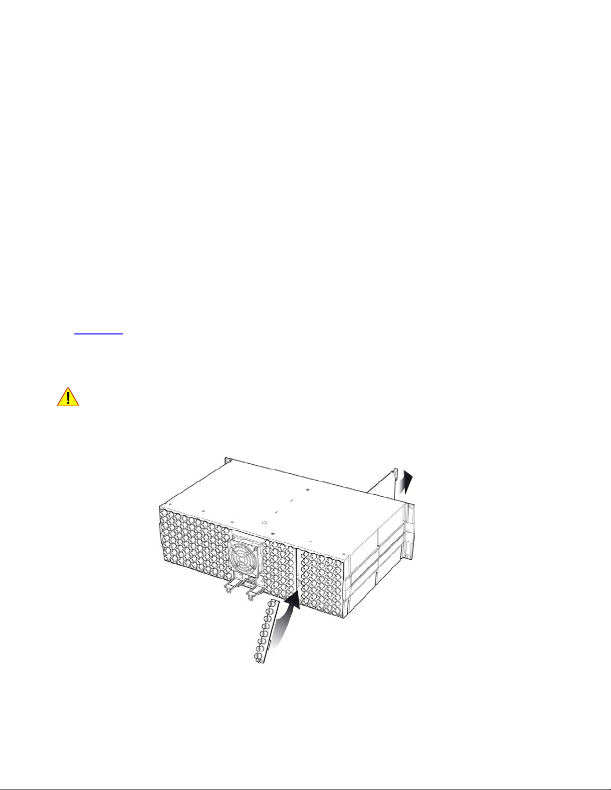
The rear connector panel must be installed with the card out of the frame.
• To remove an existing card from the slot, tilt up the swivel handle on the front of the card to lever the
Figure 2.1 Densité-3 frame – rear panel installation
for details of the signal connections available on each of these panel types.
connectors apart, then use the handle to pull the card straight out of the slot.
ADX-1901 | 3
Page 8

GUIDE TO INSTALLATION AND OPERATION
To install the connector panel:
Note – the procedure is the same for both Densité-2 and Densité-3 frames.
1. If a card is installed in the slot whose rear panel is being changed, remove it as described above.
2. Remove the existing panel (either blank or belonging to an existing card that is being changed) by releasing the
captive screw(s) at the bottom.
3. Position the new panel and secure it in place with the captive screw(s) at the bottom.
2.2 ADX-1901 Card Installation
Note – The card itself (ADX-1901) is designed to fit the D ensi t é-2 frame. If it was ordered for the Densité-3 frame
(ADX-1901-3RU), it will be delivered with an installed adapter that allows it to fit into the taller frame. The
adapter can be ordered separately and user-installed if required.
Once a matching rear connector panel is in place, install the ADX-1901 card as follows:
1. Open the front panel of the frame.
2. Slide the ADX-1901 card into the slot and push gently on the handle to seat the connectors.
When using the double-slot-width rear panel in a Densité-2 frame, the card should be inserted into the right-
most of the two slots. Inserting the card into the wrong slot will not damage the card, and will be flagged by the
on-card status LED flashing red to indicate that there is no connection to the rear panel.
3. Close the front panel of the frame.
2.3 Installation of the Optical Interface (option)
Refer to ANNEX 2
4 | ADX-1901
.
Page 9
2.4 Rear Panels and Connectors
♦ ♦
♦ ♦
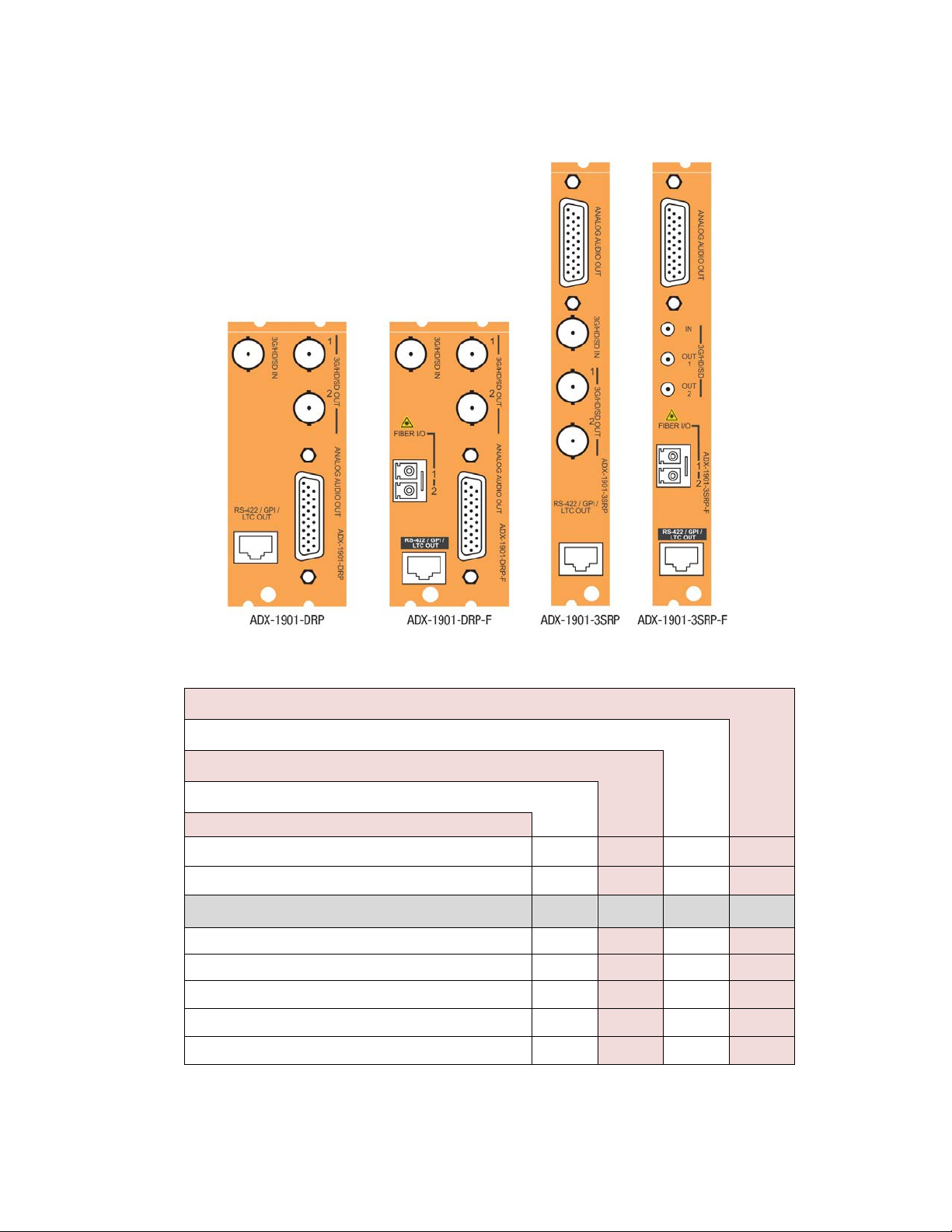
2.4.1 Images of Rear Panel Connectors
The four available rear panels are shown in the figure.
Details of the inputs and outputs are described below.
GUIDE TO INSTALLATION AND OPERATION
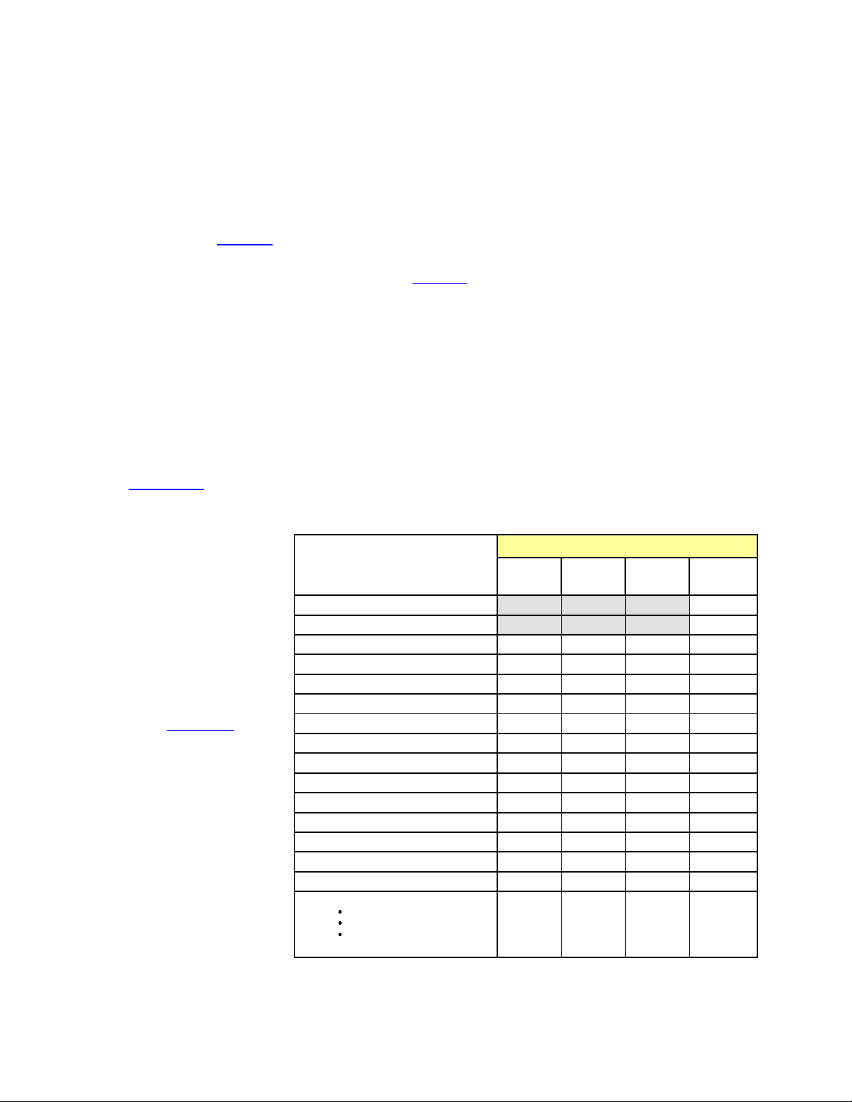
2.4.2 Summary of rear panel connections
ADX-1901-3SRP
ADX-1901-3SRP-F
ADX-1901-DRP
ADX-1901-DRP-F
Single-slot-width panel
Double-slot-width panel
CONNECTORS
3G/HD/SD IN
3G/HD/SD OUT
Analog Audio OUT on D-SUB
2 GPI OUT, LTC OUT & RS-422 OUT on RJ45
Fiber I/O module
1
2
8
yes
yes
1 1* 1
2 2* 2
8 8 8
yes yes yes
yes
* DIN1.0/2.3 connectors on ADX-1901-3SRP-F panel; BNC connectors on all other panels.
ADX-1901 | 5
Page 10
GUIDE TO INSTALLATION AND OPERATION
2.4.3 Details of rear panel connections
3G/HD/SD IN – Serial digital 3G/HD/SD input
Connect a serial digital video signal, conforming to the SMPTE 425M standard for 3G input signals, SMPTE 292M
standard for HD input signals or SMPTE 259M standard for SD input signals, to the connector labeled 3G/HD/SD IN.
The ADX-1901 will automatically switch to the detected line/frame rate format.
3G/HD/SD OUT – Serial digital video outputs
The ADX-1901 provides two 3G/HD/SD SDI video outputs on the connectors labeled 3G/HD/SD OUT 1 and 2. The
SDI video signal conforms to the input standard. The same signal is carried on both outputs.
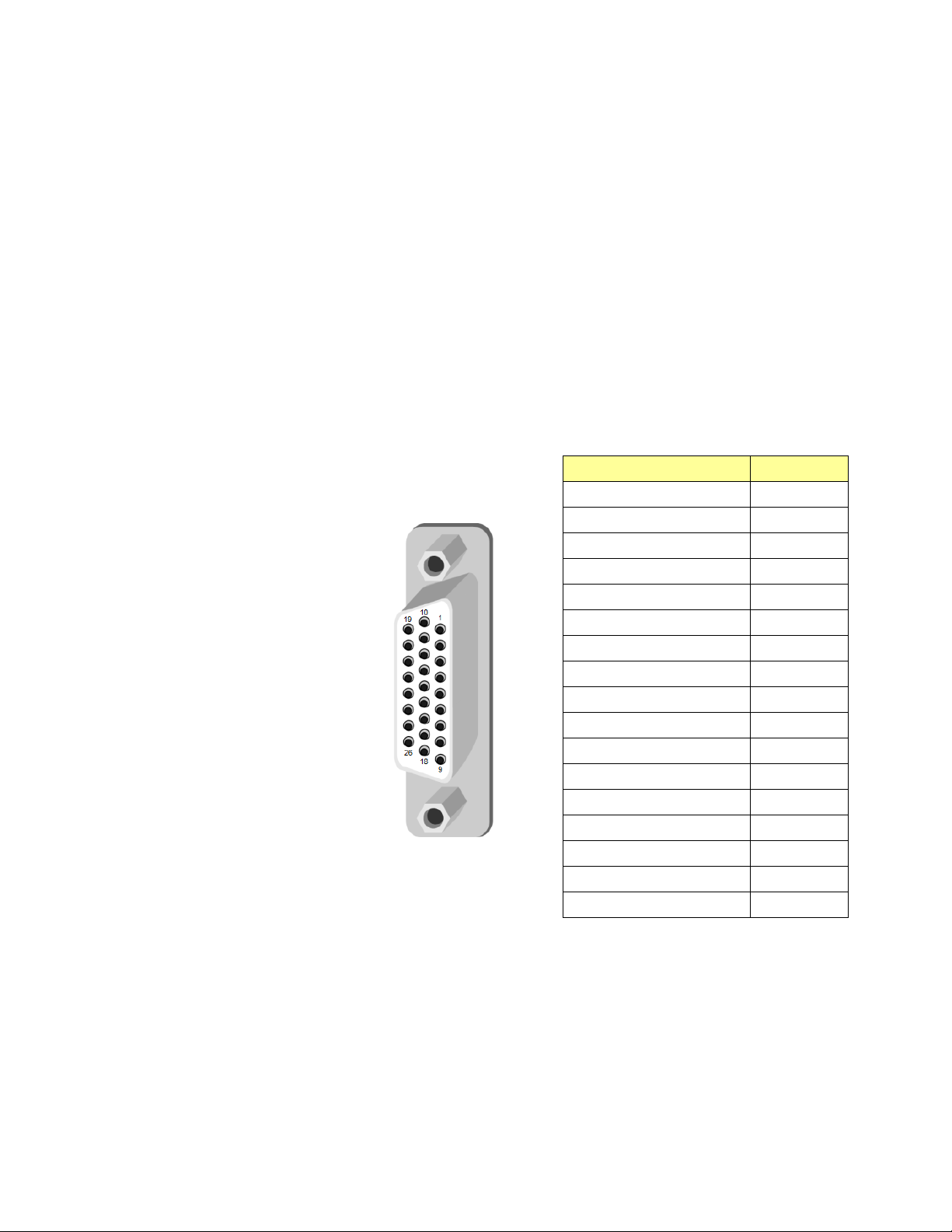
ANALOG AU D I O OUT – Analog audio outputs (8)
The eight analog audio outputs are balanced outputs, via a 26-pin D-SUB female connector. Pinout for the connector
is shown in the table.
Fiber I/O – Fiber-optic inputs and outputs
Rear panels whose part number ends in –F incorporate a fiber optic interface. The interface consists of two parts:
• A socket on the rear panel into which an SFP interface module is plugged
• An SFP (Small Form-factor Pluggable) module into which the optical fibers are plugged, and which incorporates
the optical/electrical interface
The optical fibers must be terminated in an LC/PC connector.
Signal
AUDIO OUT 1 (Hi)
AUDIO OUT 1 (Lo)
AUDIO OUT 2 (Hi)
AUDIO OUT 2 (Lo)
AUDIO OUT 3 (Hi)
AUDIO OUT 3 (Lo)
AUDIO OUT 4 (Hi)
AUDIO OUT 4 (Lo)
AUDIO OUT 5 (Hi)
AUDIO OUT 5 (Lo)
AUDIO OUT 6 (Hi)
AUDIO OUT 6 (Lo)
AUDIO OUT 7 (Hi)
AUDIO OUT 7 (Lo)
AUDIO OUT 8 (Hi)
AUDIO OUT 8 (Lo)
GND
Pin #
1
10
2
11
3
12
4
13
5
14
6
15
7
16
8
17
9, 18 to 26
6 | ADX-1901
Page 11
GUIDE TO INSTALLATION AND OPERATION
SFP Modules
Description
See ANNEX 2
for instructions on installing and removing the SFP interface module, and for plugging and unplugging
the LC-terminated fibers.
The SFP modules supported by the ADX-1901 are:
SFP-T-S13-LC Single fiber Tx (output) module at 1310 nm with LC/PC connector
SFP-TT-S13S13-LC Dual fiber Tx (output) module at 1310 nm with LC/PC connector
SFP-RT-S13-LC Dual fiber Rx (input) and Tx (output) module at 1310 nm with LC/PC connectors
SFP-R-LC Single fiber Rx (input) module with LC/PC connector
SFP-RT-W13-LC Single fiber Rx/Tx module at 1310 nm with WDM, LC/PC connector
SFP-RT-W15-LC Single fiber Rx/Tx module at 1550 nm with WDM, LC/PC connector
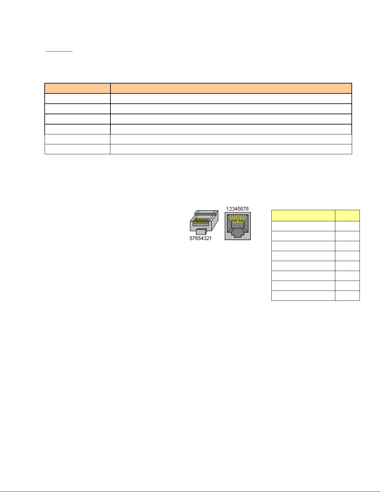
RS-422 / GPI / LTC – Metadata Output, GPI Outputs and Timecode Output
RS-422, GPI and LTC signals are carried on an RJ-45 connector, with the pinout as shown in the table:
Note: A GPI output is open when inacti ve and connected to ground when active.
Function
NC
NC
RS422-TX-1
LTC OUTPUT
GPIO USER2 OUTPUT
RS422-TX-0
GPIO USER1 OUTPUT
GND
Pin #
1
2
3
4
5
6
7
8
ADX-1901 | 7
Page 12
GUIDE TO INSTALLATION AND OPERATION
Error Condition
Flashing
Red
3 User Interface
3.1 Control options
The ADX-1901 can be controlled in three dif f er ent wa ys :
• The local control panel and its push-buttons can be used to move through a menu of parameters and to adjust
parameter values (see section 4
• Grass Valley’s iControl system can be used to access the card’s operating parameters from a remote computer,
using a convenient graphical user interface (GUI) (see sec tion 5
• Grass Valley’s RCP-200 panel (check for availability).
3.2 Card-Edge Status LED
The status monitor LED is located on the front card-edge of the ADX-1901, and is visible through the front access door
of the DENSITÉ frame. This multi-color LED indicates the status of the ADX-1901 by color, and by flashing/steady
illumination.
The chart shows how the various error conditions that can be flagged on the ADX-1901 affect the LED status.
• If a cell is gray, the error condition cannot cause the LED to assume that status
• If more than one LED status is possible for a particular error condition, the status is configurable.
See section 5.16
• The factory default status is shown by a
The LED will always show the most
severe detected error status that it is
configured to display, and in the chart
error severity increases from left to
right, with green representing no
error/disabled, and flashing red the
most severe error.
If the LED is Flashing Yellow, it
means that the card is selected for
local control using the Densité frame’s
control panel. See sec ti on 4.1
details.
for details.
for
).
).
LED Status
Hardware failure
No Rear
SFP – Absence
SFP – Type mismatch
SFP – Temperature 1
SFP – Optical Power 1
SFP – Voltage 1
SFP – Temperature 2
SFP – Optical Power 2
SFP – Voltage 2
Video – Input video error
Video – input Black Detect
Video – Audio MTDT absent
Metadata – SMPTE 2020
Metadata – DVITC.ATC
Audio – TP Overload CH1
Audio – TP Overload CH8
Green Yellow Red
8 | ADX-1901
Page 13
GUIDE TO INSTALLATION AND OPERATION
Figure
Audio – Silence Detection CH1
Audio – Silence Detection CH8
Audio – min loudness PGM1
Audio – min loudness PGM8
Audio – max loudness PGM1
Audio – max loudness PGM8
Audio – phase error CH1-2
Audio – phase error CH7-8
Audio – mute CH1
Audio – mute CH8
Audio - Test Tone
4 Local control using the Densité fra me c ont rol panel
4.1 Overview
Push the SELECT button on the ADX-1901 card edge
(see section 1.4) to assign the local control panel to
operate the ADX-1901. Use the control panel buttons
to navigate through the menu, as described below.
All of the cards installed in a Densité frame are
connected to the frame’s controller card, which handles
all interaction between the cards and the outside wor ld .
There are no operating controls located on the cards
themselves. The controller supports remote operation
via its Ethernet ports, and local operation using its
integrated control panel.
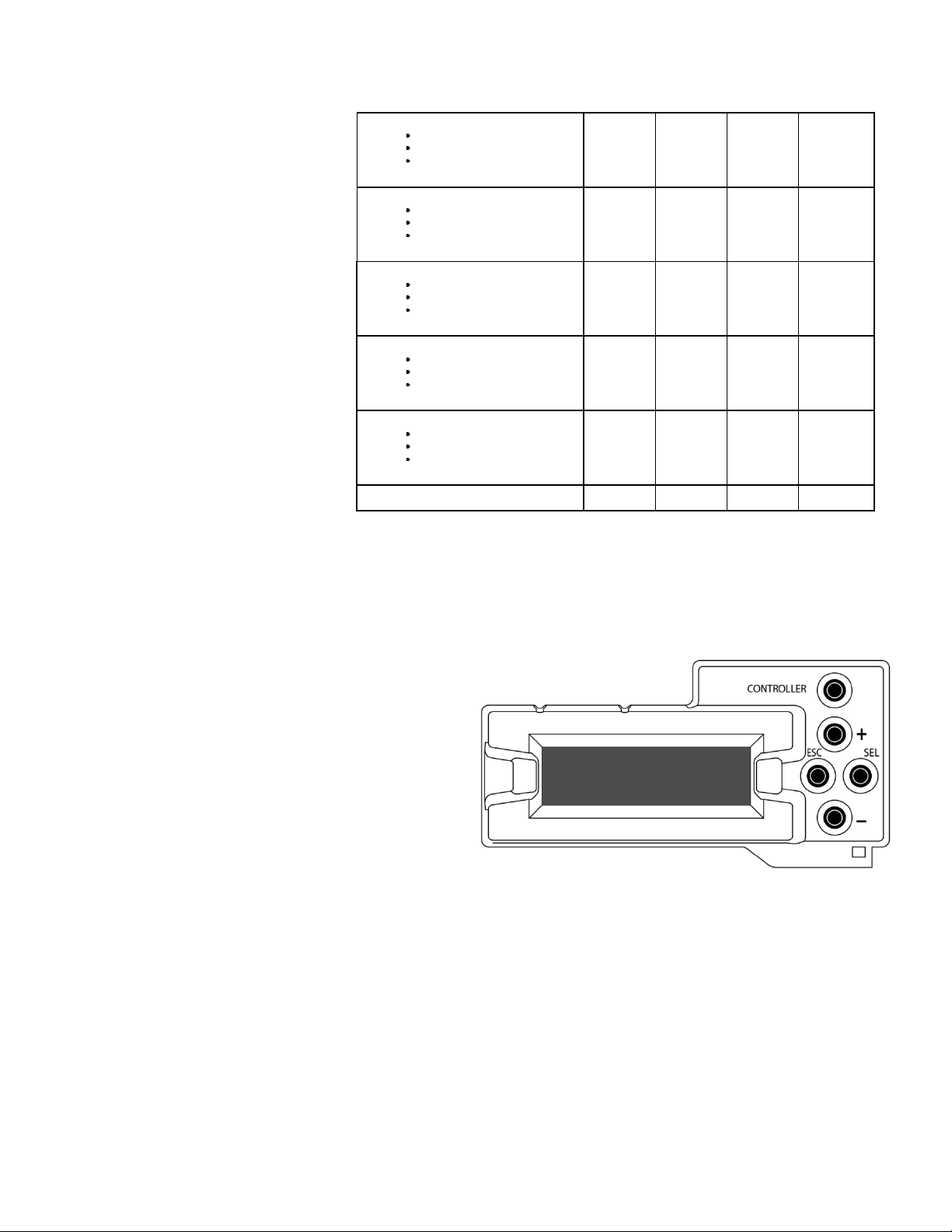
The local control panel is fastened to the front of the
CPU-ETH2 controller card, and when installed is located in the front center of the frame, positioned in front of the
power supplies. The panel consists of a display unit capable of displaying two lines of text, each 16 characters in
length, and five pushbuttons .
The panel is assigned to operate any card in the frame by pushing the SELECT button on the front edge of that card.
• Pushing the CONTROLLER button on the control panel selects the Controller card itself.
• The STATUS LED on the selected card flashes yellow.
The local control panel displays a menu that can be navigated using the four pushbuttons located beside the displa y.
The functionality of the pushbuttons is as follows:
4.1 Densité Frame local control panel
ADX-1901 | 9
Page 14

GUIDE TO INSTALLATION AND OPERATION
[+] [–] Used for menu navigation and value modification
[SELECT] Gives access to the next menu level. When a parameter value is shown, pushing this button once
enables modification of the value using the [+] and [–] buttons; a second push confirms the new value.
[ESC] Cancels the effect of parameter value changes that have not been confirmed; pushing [ESC] causes the
parameter to revert to its former value.
Pushing [ESC] moves the user back up to the previous menu level. At the main menu, [ESC] does not
exit the menu system. To exit, re-push the [SELECT] button for the card being controlled.
If no controls are operated for 30 seconds, the controller reverts to its normal standby status, and the selected card’s
STATUS LED reverts to its normal operating mode.
4.2 Menu for local control
The ADX-1901 has operating parameters which may be adjusted locally at the controller card interface.
• Press the SELECT button on the ADX-1901 front card edge to assign the Densité frame’s local control panel
to the ADX-1901
• Use the keys on the local control panel to step through the displayed menu to configure and adjust the ADX-
1901.
The complete menu structure is shown in ANNEX 1 to this document, beginning on page 41
.
10 | ADX-1901
Page 15
GUIDE TO INSTALLATION AND OPERATION
2
Figure
5 Remot e c ont rol using iControl
The operation of the ADX-1901 may be controlled using Grass Valley’s iControl system.
• This manual describes the control pan els ass oci ated w ith the ADX-1901 and their use.
• Please consult the iControl User’s Guide for information about setting up and operating iControl.
In iControl Navigator or iControl Websites, double-click on the ADX-1901 icon to open the control panel.
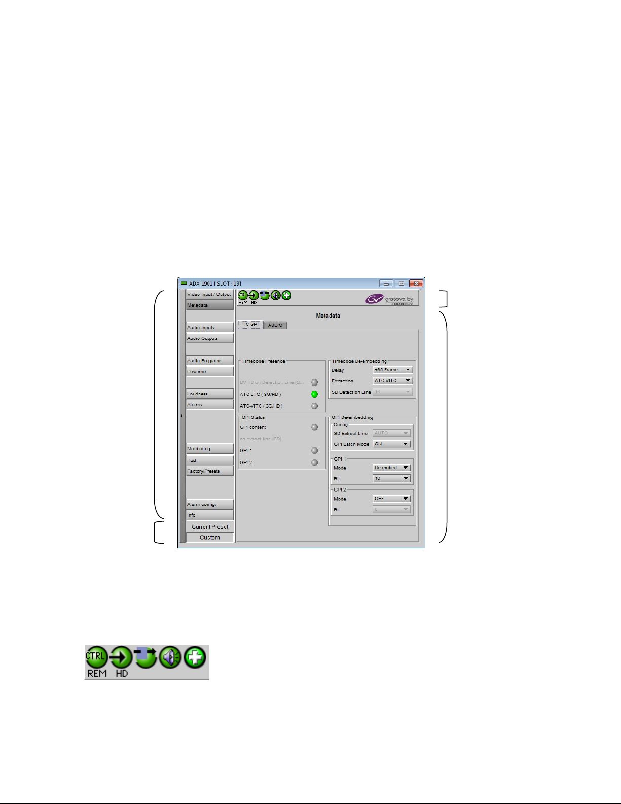
5.1 The iControl graphic interface window
The basic window structure for the ADX-1901 is shown in figure 5.1. The window identification line gives the card type
(ADX-1901) and the slot number where the card is installed in its Densité frame.
There are four main sections in the window itself, as identified in the figure:
Section 1. The top section displays five icons on the left. These icons report different statuses such as card
communication status, input signal and reference signal format and statuses. In some instances, they relate to
conditions defined through parameters settings.
Icon # 1 2 3 4 5
Move the mouse over an icon and a status message appears below the icon providing additional information.
5-1 ADX-1901 iControl graphic interface window
ADX-1901 | 11
Page 16

GUIDE TO INSTALLATION AND OPERATION
If there is an error, the error status message appears in the message area without mouse-over.
• If there are multiple errors, the error messages cycle so all can be seen
• The icon whose status or error message is shown is highlighted with a mauve background
The table below describes the various status icons that can appear, and how the y are to be interprete d.
• In cases where there is more than one possible interpretation, read the error message in the iControl window to
see which applies.
Table –iControl Status Icon interpretation
Icon #1 – Manual Card Configuration
Remote card control activated. The iControl interface can be used to operate the card
(green)
Local card control active, The card is being controlled using the Densité frame control
. Any changes made using the iControl interface will have
(yellow)
panel, as described in section 4
no effect on the card.
Icon #2 – Input status
Signal detected and valid.
(green)
• Beneath the icon, the format will be indicated as 3G, HD or SD, and the specific
format details will be listed if the cursor is moved over the icon.
No rear
(red)
Video not locked
Video input alarm disabled
(gray)
Icon #3 – Operation Mode
Operation mode: process – normal processing of the input signal
(green)
Operation mode: TEST – audio test tones enabled (see 5.11)
(yellow)
12 | ADX-1901
Page 17

Icon #4 – Analog Audio Input / Output Status
(red)
Audio OK
(green)
Yellow alarm condition detected on 1 or more channels or programs.
(yellow)
Red alarm condition detected on 1 or more channels or programs.
Icon #5 – Health Monitoring
Hardware OK
(green)
Hardware Health Monitorin g (Hard war e fault det ec ted, SFP errors).
(red)
If this icon appears flashing red, return the card to Grass Valley and specify the error code.
GUIDE TO INSTALLATION AND OPERATION
Section 2. The left portion of the window contains all the parameter groups, which become highlighted when they are
selected; the main panel (4) then displays the group’s set of parameters. Each of the groups is described in detail
below.
Section 3. The lower left corner of the window identifies the Preset currently in use or “Custom” if none is applicable.
Section 4. The main panel contains all the parameters specific to the group selected. It may contain several tabs to
help manage the different parameters.
Each of the panels assoc iated with the groups access ed from the buttons in Section 2, and show n in Section 4, is
described individually in the following sections.
5.2 Video Input/Output panel
This panel allows input selection and determination of the output in the event of loss of input signal.
The panel appearance is different for installations supporting a fiber input (i.e. using a –F rear panel) and those
without fiber support.
ADX-1901 | 13
Page 18

GUIDE TO INSTALLATION AND OPERATION
Figure
Figure
5.2.1 Video Input/Output panel (no fiber support)
When the ADX-1901 is installed with a rear panel that has no fiber
connectivity, the electrical input (BNC) is automatically selected, and
this panel has no active functions.
The current input format, or the last valid input format, is displayed in
the Output Status area.
5-2 Video Input/Output panel (no fiber)
5.2.2 Video Input/Output panel with fiber support
With fiber support, the following sections are added or activated:
Input Select: use the pulldown list to select between the copper input
(BNC) and the fiber optic input (only when a recei ver S FP m odule is
installed).
Fiber Output Config: This control is only available when a transmitter
SFP module is installed. The fiber Out 2 selector is only available
when a dual-transmitter SFP is installed.
SFP Mismatch: Illuminates Yellow if the installed SFP module is not
supported by the ADX-1901 card.
SFP Info: Displays information about the type and status of the
installed SFP module. The two columns showing status data are
labeled to reflect the type of SFP module:
• Transceiver SFP: RX-A TX-B
• Single transmitter SFP: TX-A (N/A)
• Dual transmitter SFP: TX-A TX-B
The following identifying information about the SFP module is
displayed:
• Vendor name
• Type
• Part Number
• Serial Number
• Date Code
5-3 Video Input/Output panel (with fiber)
14 | ADX-1901
Page 19

GUIDE TO INSTALLATION AND OPERATION
Figure
Additionally, some parameters are measured and their values displayed here:
• Temperature
• Voltage (V)
• Optical Power (dBm)
• Wavelength (nm)
5.3 Metadata panel
This panel contains two tabs that give access to metadata processing on the ADX-1901 card:
• TC-GPI
• AUDIO
5.3.1 TC-GPI tab
This tab controls timecode and GPI de-embedding from the input
SDI data stream.
Timecode presence:
The Status icons indicate the presence of different time code
formats – those that do not apply to the current input format are
grayed-out:
• DVITC (SD) embedded in the SDI input on the same line
that has been selected in this panel for de-embedding
• ATC-LTC (3G/HD) embedded in the SDI input
• ATC-VITC (3G/HD) embedded in the SDI input
The Timecode De-embedding section provides resources to
configure the de-embedding process.
• Delay: Adjust the timecode delay value to compensate
for a 1-to-50 frame offset between the video and the
LTC.
Value: [0, 1, 2, …, 50 frames]
• Extraction: Use the pulldown to specify the source of
extracted time code:
[OFF, DVITC, ATC-VITC, ATC-LTC, AUTO]
AUTO mode functions as follows:
o 3G/HD signal – the extracted signal will be VITC or LTC if either is present, and LTC if both are present.
o SD signal – the extracted signal will be DVITC.
.
• SD Detection Line: Use the pulldown to specify the line number to extract a time code (SD only).
[AUTO, 10 to 20 (SD525), 7 to 22 (SD625)]
In AUTO mode the ADX-1901 extracts the first timecode encountered in the vertical blanking interval. For
example, if timecode is present on lines 12 and 14, the line 12 timecode will be extracted.
5-4 Metadata Panel – TC-GPI tab
ADX-1901 | 15
Page 20

GUIDE TO INSTALLATION AND OPERATION
Figure
GPI Status: The GPI Content icon shows the presence of GPI information in the embedded timecode at the SDI input
The two GPI status icons show the status of the two GPI outputs on the rear-panel RJ45 connector.
GPI De-embedding: Set up the de-embeddi ng of GPI data from the input data streams.
• SD Extract Line: Use the pulldown to specify the line number from which to extract a time code (SD only).
[AUTO, 10 to 20 (SD525), 7 to 22 (SD625)]
In AUTO mode the ADX-1901 extracts the GPI from the first timecode encountered in the vertical blanking
interval. For example, if timecode is present on lines 12 and 14, the line 12 timecode will be extracted.
• GPI Latch Mode: When no valid time code with embedded GPI data has been detected, the user has the
option of releasing the GPI outputs (Latch mode OFF), or holding the last valid de-embedded values (Latch
Mode ON).
For each of the two GPIs:
• Mode: Use the pulldown list to select the operating mode for this GPI:
o OFF – the GPI output state is inactive.
o De-embed – the GPI data l ocated on a pre-defined user bit within timecode in the incoming SDI signal is
de-embedded.
When De-embed is selected, use the Bit pulldown list to set which of the user bits (1-16) will be
selected to de-embed the GPI data. The def ault is: GPI 1 on bit 1; GPI 2 on bit 2.
5.3.2 Audio tab
This tab provides resources to configure the input and output
selections and processing of audio metadata for the ADX-1901
card.
VANC Metadata Extractor
The card can extract an audio metadata stream from the VANC
interval.
• The icon flags the presence of the audio metadata
• Extraction is controlled by the SDID selected by the
pulldown:
(range = 01 to 09).
Delay
Use the two sliders – coarse (ms), and fine (samples) – to adjust
the delay of the extracted audio metadata b y up to 2.7 seconds
to account for video/audio timing differences.
Output Serial Stream
The de-embedded metadata can be output as an RS-422
datastream on the RJ45 rear panel connector. Select the RS422 status as OFF or Metadata using the pulldown.
The SDID is used to specify the relationship between the VANC
metadata stream and the first channel of its associated audio program.
5-5 Metadata – Audio tab
16 | ADX-1901
Page 21

SDID
Associated channel pair
01 No association, or only one audio program (default value)
Figure
02 Channel pair 1&2
03 Channel pair 3&4
04 Channel pair 5&6
05 Channel pair 7&8
06 Channel pair 9&10
07 Channel pair 11&12
08 Channel pair 13&14
09 Channel pair 15&16
5.4 Audio Inputs panel
The icons across the top of the panel indicate:
Group Detected – a green icon shows the presence of any
embedded audio groups detected in the incoming SDI s igna l.
Signal Presence – indicates the presence of audio in the 16
channels that may be carried in the embedded audio groups
• Green – audio present
• Gray – audio not present (for 2 seconds minimum)
GUIDE TO INSTALLATION AND OPERATION
5.4.1 CH 1-4, 5-8, 9-12, 13-16 tabs
These four tabs each provide individual phase and delay
controls for four of the sixteen extracted audio channels.
Phase invert – select the checkbox to invert the phase of the
channel at the input of the signal processing chain.
Fixed delay – add delay to the channel, using the two sliders,
or by typing directly into the data box:
• Coarse delay (range = 0 to 2700 msec)
• Fine delay (range = 0 to 47 samples)
Maximum delay is limited to 2.7 s.
5-6 Audio Inputs panel – Analog 1-4 tab
ADX-1901 | 17
Page 22

GUIDE TO INSTALLATION AND OPERATION
Figure
5.4.2 The Status tab:
Audio Type Status – the format of audio signals in each of the
16 audio channels is indicated by the text inside each icon.
Figure 5-7 Audio Input panel - Status
5.5 Audio Output panel
The ADX-1901 provides eight analog audio outputs, selected from amongst the 16 channels extracted from the SDI
input. This panel provides selection and audio processing for the eight analog audio outputs:
• audio channel shuffling
• level adjustment
• mixing
5.5.1 1-2, 3-4, 5-6, 7-8 tabs
Each of these tabs provides all necessary controls for the
output mixers. The example shown is for 1-2 output, but all
panels have the same controls.
Operation Mode (Off, A, SUM(A+B), Mix) : This menu allows
the source(s) of each output channel to be selected – a single
channel, the sum of two channels, or a mix of two channels.
Off: The output channel is muted.
A: The output channel is the source selected in sub-menu
SOURCE A.
SUM (A+B): The output channel is the sum of the two
source channels selected in sub-menus SOURCE A and
SOURCE B.
5-8 Audio Output panel – 1-2 tab
18 | ADX-1901
Page 23

GUIDE TO INSTALLATION AND OPERATION
Figure
• If you select this option, the S UM (A+B) Level pull-down is activated, allowing you to reduce the level of the
summed output (0dB, -3dB or -6dB).
Mix: The output channel is a mono mix of source channels selected in sub-menus SOURCE A and SOURCE B.
Mute: Mute the audio channel by checking this box.
Clipping: indicates a very high level at the output, resulting in signal clipping.
Source A & Source B: These sub-sections allow the source channels (A and B) to be selected for each output
channel.
Channel: CH 1, …, CH 16: selects the demuxed input channel to be used for this output channel mixer input.
Level (dB): Sets the audio gain of the source from -96 to +12 dB in 0.5 dB steps
5.5.2 Config tab
0 dBFS Output – The tab contains a single pulldown allowing
selection of the digital-to-analog conversion ratio for maximum
output level.
Choices available: 0 to +24 dBu
5-9 Audio Output - Config tab
ADX-1901 | 19
Page 24

GUIDE TO INSTALLATION AND OPERATION
2/1
X X X 2/1L
X X X X 3/1
X X X X
3/1L
X X X X X
2/2
X X X X 2/2L
X X X X
X
Figure
5.6 Audio Programs panel
The Audio Programs panel provides resources to define eight
audio programs, and to specify the inputs for each program.
Coding Mode:
Use the eight pull-downs to specify the coding of the programs
that you want to appear on the 8 analog audio outputs. The
options are:
Coding
Mode
Left Right Center LFE Ls Rs
1/0 X
2/0 X X
3/0 X X X
3/0L X X X X
Program Channels
5-10 Audio Programs panel
3/2 X X X X X
3/2L X X X X X X
OFF This program is not used
The graphic at the bottom of the panel illustrates the selected programs, and provides pull-downs to choose the audio
input that feeds each program input.
Note 1: An input channel cannot be assigned to more than one (1) program, and can o nly be used once within a
program.
Note 2: The programs defined here are the programs available for Loudness monitoring and Downmix
.
Global Config:
Use the Meter Mode pull-down to select the parameters that will be used for all audio level measurements on this
ADX-1901.
Mode
EBU R128 2011 LUFS -23 3 sec -10 dB
A85 ITU BS.1770-3 LKFS -24 10 sec -10 dB
ARIB TR-B32 LKFS -24 3 sec -10 dB
Loudness
Unit
Target
Short-Term
Time Window
Relative
Gating
20 | ADX-1901
Page 25

GUIDE TO INSTALLATION AND OPERATION
Figure
Each of these has predetermined values for Target, Short Term Time Window and Relative Gating, as shown in the
table, and which are displayed in gray in their (inactive) pull-downs in the panel.
If you select Custom in the Meter Mode pull-down, these parameters can all be selected in order to define a custom
mode.
5.7 Downmix panel
This tab provides resources to control the downmix of a “5.1 channel”
surround-sound audio signal into an LoRo stereo pair. The 5.1
terminology refers to six discrete audio channels, with the low frequency
effect (LFE) channel of limited bandwidth designated as the “.1” channel.
The Input channels are automatically ass ig ned to the 3/2 or 3/2L
program defined in the "Audio Program" tab. If no such program is
defined, the panel is inoperative and a warning is displ a yed:
Downmix:
Operating Mode: Use the pulldown to select the downmix operating
mode:
• OFF: Downmix is disabled. Input channels pass through
unchanged.
• Manual: Downmix follows the downmix parameters manually
configured by the user.
Level Normalization: use the pulldown to select the type of normalization to be applied on the downmix output level.
• OFF: Downmix output level is not normalized. Clipping may occur depending on the input channel levels and
the selected mix levels.
• Level A: Downmix output level is normalized based on the applied mix levels to provide a uniform output over
the range of mix levels available. Clipping will never occur, even with full scale input channels and mix
levels.
Output Channels: Select the audio channels whose content will be replaced by the output of the downmix processor
• 1-2
• 3-4
• 5-6
• 7-8
• This selection is not available when the Operating Mode is OFF (downmix disabled).
Manual Downmix Config
• When Manual Operating Mode is selected in the pulldown above, these controls are active.
Mode: this pulldown menu selects the downmix mode, which is forced to the default value:
• LoRo: Enables the downmix of 5.1 channels into an LoRo (Left only Right only) stereo pair, which is a
conventional stereo signal. The input signals on the channel pair selected as the Output Channels are
discarded.
5-11 Downmix tab
ADX-1901 | 21
Page 26

GUIDE TO INSTALLATION AND OPERATION
Surround
Level
Center
Level
+
+
+
+
+
+
+
Ls
Rs
Lo
Ro
L
R
C
Surround
Level
+
LFE
Level
+
+
+
+
LFE
Figure
Dialnorm: this pulldown selects the dialog normalization level. Select OFF to prevent the downmix from applying the
dialnorm.
[OFF, -12 dBFS, -13 dBFS, -14 dBFS, ………, -31 dBFS]
Center Mix Level – sets the center channel downmix level to the selected value
[+3 dB, +1.5dB, 0 dB, -1.5 dB, -3 dB, -4.5 dB, -6 dB, Mute]
Surround Mix Level – sets the surround channels (Ls & Rs) downmix level to the selected value
[+3 dB, +1.5dB, 0 dB, -1.5 dB, -3 dB, -4.5 dB, -6 dB, Mute]
LFE Mix Level – sets the LFE channels downmix level to the selected value.
[+10 dB, +9 dB, +7.5 dB, +6 dB, +4.5 dB, +3 dB, +1.5dB, 0 dB, -1.5 dB, -3 dB, -4.5 dB, -6 dB, Mute]
The block diagram below shows the configuration of the LoRo stereo downmixer.
Figure 5-12 Lo/Ro downmixer
5.8 Loudness Panel
The ADX-1901 allows the user to measure the loudness of audio streams passing through it. The measurement
process is flexible:
• All major loudness standards are supported.
• The measurement standards can be customized if desired.
• Up to eight programs can be measured at once.
• Segment markers can be inserted from two triggers.
• Log files of the measurements can be stored externally, for
analysis using Miranda’s Audio Loudness Analyzer.
5.8.1 Loudness | Config panel
Global Config
All loudness measurements performed by this ADX-1901 are
performed on the programs defined in the Audio Programs Panel
using the metering defined and described in that panel.
Global Control
The ADX-1901 can monitor loudness on up to eight programs
specified by the user.
,
5-13 Loudness panel – Config tab
22 | ADX-1901
Page 27

GUIDE TO INSTALLATION AND OPERATION
Figure
Enable Loudness Monitoring turns all loudness monitoring functions ON or OFF
RESET resets the measurements, and places a segment marker in the log file (but only if User Event is selected in
the Segment Marker area).
RUNNING / PAUSE shows the current status of the loudness monitoring.
• Click the button to change the status.
• PAUSE stops the measurement until the button is clicked again, but keeps the last value for logging and
measurement.
Segment Marker
Select the checkboxes corresponding to the events for which you want a segment marker inserted in the loudness log
file:
• User Event – a manually-triggered RESET (but not a PAUSE).
• Target change – a manually-triggered Meter Mode or Target change in the Audio Programs tab.
Note that segment marker triggers in one PGM will generate segment markers in the logs for all PGMs.
Logging Status/Control
This panel monitors logging activity for all loggers connected to the application server associated with this ADX-1901
and its associated Densité frame.
• The Logging Activity icon will be GREEN when logging activity is detected.
• The number of loggers connected to the appserver is shown in the data box.
About Log Files
Loudness logs contain data for a period of up to 24 hours. New log files are started when the logging function is
enabled.
5.8.2 Loudness | PGM panel
Eight PGM panels – PGM 1 to PGM 8 – are available. These
panels show the results of loudness measurements made on
this program.
Program Settings & Input Channel Settings
These data boxes show the program definition – the coding
mode and channel selections are those made in the
Programs panel.
Audio
5-14 Loudness panel – PGM 1 tab
ADX-1901 | 23
Page 28

GUIDE TO INSTALLATION AND OPERATION
3/0 X X X
3/0L X X X X
2/1 X X X
2/1L X X X X
3/1 X X X X
3/1L X X X X X
3/2L X X X X X X
Coding
Mode
Left Right Center LFE Ls Rs
Program Channels
1/0 X
2/0 X X
2/2 X X X X
2/2L X X X X X
3/2 X X X X X
Measurements
The Measurements area displays results from the loudness measurements performed on the selected program
according to the settings made in the Lou dnes s | Config tab and the Audio Programs panel. The three data boxes
show these values:
• True peak MAX Maximum true peak level found in all selected input channels
• Momentary MAX Loudness averaged over a 400 ms sliding rectangular time window
• Short term (S) Loudness averaged over the short-term time window
The chart shows a running plot of the last 15 seconds of the value of the Short Term (yellow trace) and Momentary
(green trace) loudness values. The bar graph at the right indicates the current Momentary value.
A reset, initiated by a user via the Reset button on the Loud nes s | Config tab, will reset all of these measurements.
About Log Files
Loudness logs contain data for a period of up to 24 hours. New log files are started:
• when the logging function is enabled
• every 24 hours after logging was enabled, until logging is disabled
• when the reference changes
• when the global config is changed,
See _ANNEX_3_-ANN EX 3 - Loudness Logging and the Miranda Audio Loudness Analyzer beginning on page 44
for detailed instructions on activat ing log gi ng and ana l yzin g the logg ed data files.
5.9 Alarms panel
This panel provides resources to set the detection conditions and card response for each of the alarms supported by
the ADX-1901.
5.9.1 Alarms – Video panel
Only one video alarm is defined.
24 | ADX-1901
Page 29

Video Black Detection
Figure
Figure
This alarm detects the presence of a continuous black signal on
the input for a period of time; the condition is flagg ed o nly when
the time duration criterion has been satisfied.
Enable the alarm by selecting the checkbox.
The user sets the detection parameters for this error using three
sliders:
• Threshold (mV) – sets the signal level below which Black
will be considered to have been detected.
• Set Duration (sec) – sets the time interval over which
Black must be continuously detected before the error is
flagged.
• Clear Duration (sec) – sets the time interval over which a
non-black signal (i.e. above the Threshold) must be
continuously present to clear the alarm if it has been set.
Use the LED Color pulldown to choose the color that will be
displayed by the status LED on the card edge when a Black
Detect alarm is set. Choices are:
GUIDE TO INSTALLATION AND OPERATION
• Green, Yellow, Red, Flashing Red
Zone settings – def ine a zone with in whic h the al arm detection
will be applied.
• Line: Start Stop
• Pixel: Start Stop
The ranges always start at 1, but the upper limit depends on the
video format. The zone is indicated by the black line and the
video image size by the gray window.
5.9.2 Alarms – Metadata panel
SMPTE2020 Metadata
This alarm checks the presence of audio metadata inserted
(SMPTE-2020) in the input video signal.
Enable the alarm by selecting the checkbox.
The user sets the detection parameters for this error using two
sliders:
• Set Duration (sec) – sets the time interval over which
Audio Metadata must be continuously absent before the
condition is flagged and the alarm is set.
• Clear Duration (sec) – s ets the time interval over which
Audio Metadata must be continuously present to clear the
alarm if it has been set.
5-15 Alarms panel – Video – Input Black
5-16 Alarms – Metadata – SMPTE 2020
ADX-1901 | 25
Page 30

GUIDE TO INSTALLATION AND OPERATION
Figure
Figure
Use the LED Color pull-down to choose the color that will be displayed by the status LED on the card edge when a
SMPTE-2020 alarm is set. Choices are:
• Green, Yellow, Red, Flashing Red
DVITC/ATC
This alarm checks the presence of a DVITC or an ATC Time
Code inserted in the input video signal.
Enable the alarm by selecting the checkbox.
The user sets the detection parameters for this error using two
sliders:
• Set Duration (sec) – sets the time interval over which
DVITC/ATC must be continuously absent on the video
input before the condition is flagged and the alarm is set.
• Clear Duration (sec) – sets the tim e interval over which
DVITC/ATC must be continuously present to clear the
alarm if it has been set.
Use the LED Color pull-down to choose the color that will be
displayed by the status LED on the card edge when a
DVITC/ATC alarm is set. Choices are:
• Green, Yellow, Red, Flashing Red
5.9.3 Alarms – Audio panel
The Audio alarms are detected after the Audio Output stage, just
before the Digital to Analog converters.
Overload
The overload detection is True Peak.
• Enable the alarm by selecting the checkbox.
• Select the Apply To All checkbox to apply the next alarm
settings modifications simultaneously to all eight channels.
The user sets the detection parameters for this error using three
sliders:
• Threshold (dBFS) – sets the signal level above which an
overload will be considered to have been detected.
• Set Duration (sec) – sets the time interval over which an
overload must be continuously detected before the error is
flagged.
• Clear Duration (sec) – sets the time interval over which a
non-overload signal (i.e. below the Threshold) must be
continuously present to clear the alarm if it has been set.
Use the LED Color pulldown to choose the color that will be
5-17 Alarms – Metadata – DVITC
5-18 Alarms – Audio – Overload
26 | ADX-1901
Page 31

GUIDE TO INSTALLATION AND OPERATION
Figure
Figure
displayed by the status LED on the card edge when an Overload alarm is set. Choices are:
• Green, Yellow, Red, Flashing Red
Max Level
This parameter is measured for the eight programs defined in the
Audio Programs panel, and uses the Momentary Loudness
values.
• Enable the alarm by selecting the checkbox.
• Select the Apply To All checkbox to apply the next alarm
settings modifications simultaneously to all eight programs.
The user sets the detection parameters for this error using three
sliders:
• Threshold (dBFS) – sets the signal level above which Max
Level will be considered to have been detected.
• Set Duration (sec) – sets the time interval over which Max
Level must be continuously detected before the error is
flagged.
• Clear Duration (sec) – sets the time interval over which a
non-Max-Level signal (i.e. below the Threshold) must be
continuously present to clear the alarm if it has been set.
Use the LED Color pulldown to choose the color that will be
displayed by the status LED on the card edge when a Max Level
alarm is set. Choices are:
5-19 Alarms – Audio – Max Level
• Green, Yellow, Red, Flashing Red
Min Level
This parameter is measured for the eight programs defined in the
Audio Programs panel, and uses the Momentary Loudness
values.
• Enable the alarm by selecting the checkbox.
• Select the Apply To All checkbox to apply the next alarm
settings modifications simultaneously to all eight programs.
The user sets the detection parameters for this error using three
sliders:
• Threshold (dBFS) – sets the signal level below which Min
Level will be considered to have been detected.
• Set Duration (sec) – sets the time interval over which Min
Level must be continuously detected before the error is
flagged.
• Clear Duration (sec) – sets the time interval over which a
non-Min-Level signal (i.e. above the Threshold) must be
continuously present to clear the alarm if it has been set.
5-20 Alarms – Audio – Min Leve l
ADX-1901 | 27
Page 32

GUIDE TO INSTALLATION AND OPERATION
Figure
Figure
Use the LED Color pulldown to choose the color that will be displayed by the status LED on the card edge when a Min
Level alarm is set. Choices are:
• Green, Yellow, Red, Flashing Red
Silence
• Enable the alarm by selecting the checkbox.
• Select the Apply To All checkbox to apply the next alarm
settings modifications simultaneously to all eight channels.
The user sets the detection parameters for this error using three
sliders:
• Threshold (dBFS) – sets the signal level below which
Silence will be considered to have been detected.
• Set Duration (sec) – sets the time interval over which
Silence must be continuously detected before the error is
flagged.
• Clear Duration (sec) – sets the time interval over which a
non-silent signal (i.e. above the Threshold) must be
continuously present to clear the alarm if it has been set.
Use the LED Color pulldown to choose the color that will be
displayed by the status LED on the card edge when a Silence
alarm is set. Choices are:
5-21 Alarms – Audio – Silence
• Green, Yellow, Red, Flashing Red
Phase
The Phase measurements are limited to adjacent channel pairs.
• Enable the alarm by selecting the checkbox.
• Select the Apply To All checkbox to apply the next alarm
settings modifications simultaneously to all four channel
pairs.
The user sets the detection parameters for this error using three
sliders:
• Threshold (degrees) – sets the value above which a
phase error will be considered to have been detected.
• Set Duration (sec) – sets the time interval over which a
phase error must be continuously detected before the
error is flagged.
• Clear Duration (sec) – sets the tim e interval over which an
in-phase signal (i.e. below the Threshold) must be
continuously present to clear the alarm if it has been set.
Use the LED Color pulldown to choose the color that will be
displayed by the status LED on the card edge when a Phase
alarm is set. Choices are:
• Green, Yellow, Red, Flashing Red
28 | ADX-1901
5-22 Alarms – Audio – Phase
Page 33

GUIDE TO INSTALLATION AND OPERATION
Figure
Figure
5.10 Monitoring panel
The Remote Audio Level Meter (RALM) panel displays audio
output level meters for the 8 analog outputs. Channels are
displayed in pairs, so up to four meters will be present in the
meter display window. The source for each meter is selected
using the pulldowns in the RALM Remote Control area at the
bottom of the control panel.
• OFF
• Audio Output CH 1&2 up to CH 7 & 8
The meter is divided into three zones, and the dividing points
and color of each zone are individually configurable under the
Meter Ballistics Config tab.
Speed – select the meter response from the pull-down list,
options are [ fast, medium, slow ]
5.10.1 RALM Connections tab
Use the radio buttons to turn the meter display ON (RALM) or
OFF for the indicated channels. The meter appears directly
above the controls.
Reset Counter: click this button to reset the overload counter
on the ALM display to zero. See the next section for instructions on setting up the overload counter.
5-23 Monitoring - RALM
5.10.2 Meter Ballistics Config tab
Type – select a type of meter from the pull-down
list
Upper Zone Limits – s elect the cros sover le ve l
between the upper and middle zones of the meter
(the range of values shown in the pull-d o w n lis t
depends on the type of meter selected)
Lower Zone Limits – s elect the cros sover le ve l
between the middle and lower zones of the meter
(the range of values shown in the pull-down list depends on the type of meter selected)
Color samples – the three samples show the current selected color for the upper, middle and lower zones of the
meter.
• Click on the color sample of a zone to open a color selection panel to choose a different color for that zone
Overload Cursor – The overload cursor appears on the meter as an arrowhead in the meter scale. The two pull-down
boxes set the position of the overload cursor on the left and right meters. If the audio level on a channel goes above
the cursor, the Overload Counter at the top of the meter is incremented.
This counter shows a running count of the number of overloads detected.
5-24 RALM - meter ballistics configuration
ADX-1901 | 29
Page 34

GUIDE TO INSTALLATION AND OPERATION
Figure
Figure
The Phasemeter (located at the bottom of the RALM meter display) is a
small meter that represents the phase correlation factor between the two
channels of a pair.
180° 90° 0
5-25 RALM meter display
5.11 Test panel
Use the checkboxes to s elect whether each output pair has an
EBU tone forced onto the outputs.
5-26 Test panel
30 | ADX-1901
Page 35

5.12 Factory/Presets panel
Figure
Figure
Factory Section
Load Factory: Clicking this button will restore the card to a factory
default state. Two checkboxes enable the user to choose whether
to include Parameters and/or Alarms in the restoration process
• Note that User Presets are not changed
User Presets section
The ADX-1901 has memory registers which can hold up to 5 userdefined parameter settings.
The Current Preset box (at the bottom left corner of the panel)
displays the last loaded preset. Any change to the card
configuration after a preset is loaded will change the display to
"Custom" instead of the preset value.
Select any one of the five pres ets using the pull-down list.
Click Load to load the contents of the selected User Preset into
the ADX-1901. All parameter settings and values will be replaced
by the contents of the selected User Preset.
•
Click Save to store the current parameter settings and values
from the ADX-1901 into the selected User Preset. The existing
contents of the preset will be overwritten.
GUIDE TO INSTALLATION AND OPERATION
5-27 Factory / Presets panel
Profiles
This section provides the option to save and recover the entire card configuration (including user presets if desired) on
an external disk, or to copy it to another ADX-1901 card.
Click on Profiles to open the Profile Copy window.
5-28 Profile Copy window
ADX-1901 | 31
Page 36

GUIDE TO INSTALLATION AND OPERATION
Figure
Figure
Copy profile from
This line shows this ADX-1901 card, and identifies it b y App server, Densité frame and slot number, card type an d
firmware version.
The Profile column has a pulldown that allows you to select which profiles you will work with, and gives these choices:
• Current, User1, User2, User3, User4, User5, All
The Select column includes a checkbox (preselected checked) to confirm that you want to work with the current card.
Save Profile to Disk…
Click this button to open a Save dialog allowing you to specify a
file name and location to which the selected profiles for this
card will be saved.
Hint - It is a good idea to create a folder for these files, because
they are not explicitly identified as ADX-1901 profiles, and will
be difficult to find and identify if not clearly named and
conveniently located.
• Click the save button once the name and location have
been identified in the Save box
• If the file is saved correctly, the Transfer Status box on
the right of the Copy profile from line will indicate
Succeeded against a green background:
• If the file was not saved for some reason, the Transfer
Status box to the right of the Copy profile from line will
indicate Failed against a red background:
Restore profiles from disk…
Click this button to open an Open dialog box with in whi c h you
can locate and select a valid ADX-1901 profile file.
• Click Open to read the contents of the file and to
reconfigure this ADX-1901’s profiles according to its
contents
• While the reconfiguration is in progress, the Transfer
Status box on the right of the Copy profile from line will
indicate Working against a yellow background
• When the reconfiguration is complete, the Transfer Status
box on the right of the Copy profile from line will indicate
Succeeded against a green background
Copy Profile to
This line shows other ADX-1901 cards that are available on the
iControl network, each identified by App server, Densité frame
and slot number, card type and firmware version
5-29 Save Profile to Disk dialog
5-30 Restore Profiles from Disk dialog
32 | ADX-1901
Page 37

The Profile column s hows the s am e inform ation as is sho wn for the
Figure
current card in the Copy profile from line, i.e. one of the following:
• Current, User1, User2, User3, User4, User5, All
The Select column includes a checkbox to identif y the ADX-1901
cards onto which you will copy profiles from the current card.
• For convenience, a Select all checkbox is provided in the
column header
• Note that you can onl y select ADX-1901 cards with the same
firmware version as the source card; cards with a different
firmware version will sh ow N/A against a yellow backgroun d
in the Transfer Status column.
Click Copy to copy the selected profiles from this card into the
selected other ADX-1901 cards
• While the profile copy operation is in progress, the Transfer
Status box on the right of the Copy profile to line will indicate
Working against a yellow background
• When the profile copy operation is complete, the Transfer
Status box on the right of the Copy profile to line will indicate
Succeeded against a green background
5.13 Alarm Config panel
This panel allows the alarm reporting of the ADX-1901 to be
configured. The panel opens in a new window when th e button is
clicked, and can be resized if needed.
The panel is organized in columns.
Status/Name
This contains an expandable tree listing all the alarms reported by
this ADX-1901 card.
• Each alarm name includes an icon that shows its current
status
• Some alarms may be text-only and the alarm status is shown
in the name and not by a status icon
• The figure shows the entire tree, but some repetitive alarms
were removed to reduce the size of the image.
The Card LED and Overall alarm columns contain pulldown lists
that allow the level of contribution of each individual alarm to the
alarm named in the column heading to be set.
• If there is no arrowhead in the box, there is no pulldown and
the alarm is not user-configurable
Card LED
This column allows configuration of the contribution of selected
individual alarms to the status LED located on the front card edge.
The Card LED status is shown at the bottom of the alarm tree in the
Status/Name column.
GUIDE TO INSTALLATION AND OPERATION
5-31 Alarm Co nfiguration panel
ADX-1901 | 33
Page 38

GUIDE TO INSTALLATION AND OPERATION
Figure
Overall Alarm
This column allows configuration of the contribution of each individual alarm to the Overall Alarm associated with this
card. The Overall Alarm is shown in the upper left corner of the iControl panel, and also appears at the bottom of the
Status/Name column.
GSM Contribution
This column allows configuration of the contribution of each individual alarm to the GSM Alarm Status associated with
this card. GSM is a dynamic register of all iControl system alarms, and is also an alarm provider for external
applications. The possible values for this contribution are related to the Overall alarm contribution:
• If the Overall alarm contribution is selected as Disabled, the GSM alarm contribution can be set to any available
value
• If the Overall alarm contribution is selected as any level other than disabled, the GSM contribution is forced to
follow the Overall Alarm.
Log Events
iControl maintains a log of alarm events associated with the card. The log is useful for troubleshooting and identifying
event sequences. Click in the checkbox to enable logging of alarm events for each individual alarm.
Levels associated with these alarms:
The pulldown lists may contain some or all of the following options:
The alarm makes no contribution (black icon)
The alarm is of minor importance (yellow icon)
The alarm is of major importance (orange icon)
The alarm is of critical importance (red icon)
The alarm exists but has no effect (used for text and composite alarms)
Shortcut: if you click in one of the Set All boxes beside a section heading, you will open a pulldown that lets you
assign a level to all alarms in that section of the column simultaneously.
Once the alarms are configured, you may accept the changes or discard them:
Overall alarm and GSM contribution follow card LED
Click in the checkbox to force the Overall alarm and GSM
contribution to be identical to the Card LED status
• All Overall alarms and GSM contributions for which
there is a Card LED alarm will be forced to match the
Card LED alarm
• All Overall Alarms and GSM contributions for which
there is no Card LED alarm will be forced to Disabled
A warning box will open allowing you to confirm the action,
since it will result in changes to the configuration and there
is no undo function.
5-32 Warning for Follow LED change
34 | ADX-1901
Page 39

GUIDE TO INSTALLATION AND OPERATION
Figure
Figure
Copy to other cards
Click this button to open a panel that allows the alarm
configuration set for this card to be copied into another ADX1901 card.
• Select one or more destination cards from the list in the
window by clicking in the checkboxes, or all of them by
clicking in the All checkbox
• Note that when you do a Copy Profile
section 5.14), the alarm configurati on is copied al ong
with all the other settings.
Get alarm keys
Click this button to open a save dialog where you can save a
file containing a list of all alarms on this card and their current
values, along with an Alarm Key for each. The alarm keys are
useful for system integration and troubleshooting.
• The file is saved in .csv format
OK, Apply, Cancel
• OK accepts the settings and closes the window once the card confirms that there are no errors.
• Apply accepts the settings, but leaves the window open
• Cancel closes the window without applying any changes, and leaves the previous settings intact.
for this card (see
5-33 Copy to Other Cards window
5-34 Get Alarm Keys dialog
ADX-1901 | 35
Page 40

GUIDE TO INSTALLATION AND OPERATION
Figure
Figure
Figure
5.14 Info panel
When the ADX-1901 is included in an iControl environment,
certain information about the card should be available to the
iControl system. The user can enter labels and comments that
will make this card easy to identify in a complex setup. This
information is entered into data boxes in the Info control panel.
Rear Type: specifies the rear module currently installed.
Label: type the label that is shown for this ADX-
1901 when it appears in iControl
applications
Short Label type the short-form label that iControl uses
in some cases (8 characters)
Source ID type a descriptive name for this ADX-1901
Comments: type any desired text
The remaining data boxes show manufacturing information
about this card.
Three buttons in the panel give access to other inform at ion.
• Details…: Reports the Firmware version, service version,
and panel version for this card
• Advanced…: Shows the Long ID for this card. The Long ID is the
address of this ADX-1901 in the iControl network.
5-35 Info panel
5-36 Details window
5-37 Advanced window
36 | ADX-1901
Page 41

GUIDE TO INSTALLATION AND OPERATION
Figure
• Remote System Administration – opens the Joining Locators window,
which lists remote lookup services to which this ADX-1901 is registered
Add: Force the iControl service for this ADX-1901 to register itself on a
user-specified Jini lookup service, using the following syntax in the data
box:
jini://<ip_address>
where <ip_address> is the ip address of the server running the
lookup service, e.g.:
Remove: select one of the services listed in the window by clicking on it, and click Remove to open a quer y
box allowing you to delete it from the window.
5-38 Joining Locators window
ADX-1901 | 37
Page 42

GUIDE TO INSTALLATION AND OPERATION
6 Specifications
Analog Audio Outputs (8)
Signal: balanced analog audio
Impedance: < 60Ω
Max. level: +24 dBu / 2 KΩ
Audio Processing Performance
Quantization: 24 bits
Sampling: 48 kHz
Audio latency: 0.967 ms at 48 kHz
Audio delay: Up to 2.7s (1 ms steps and 1 sample steps)
SNR: >116 dB A weighted
0 dBFS: 0 to +24 dBu (1 dB steps)
Distortion: <-90 dB (20Hz to 5 kHz)
Crosstalk: <-110 dB (20 Hz to 20 kHz)
Freq. response: ± 0.05 dB (20 Hz to 20 kHz)
Tone generator: -18 dBFS 1 kHz sine wave interrupted on left channel (250 ms) per EBU
R49
Video Input / Output
Signal: SMPTE 259M-C (270 Mb/s)
SMPTE 292M (1.485, 1.485/1.001 Gb/s)
SMPTE 424M (2.970, 2.970/1.001 Gb/s)
Supported formats: SD: SMPTE 259M: 4 80 i59. 94, 576 i50
HD: SMPTE 274M: 1080i59.94, 1080i50, 1080p23.98, 1080psf24,
1080p25, 1080p29.97
HD: SMPTE 296M: 720p59.94, 720p50, 720p23.98, 720p24
3G: SMPTE 425M Level A (mapping 1), Level B: 1080p59.94, 1080p50
Embedded audio: SMPTE 272M (SD), SMPTE 299M (HD)
Embedded ATC: SMPTE RP188
Embedded ANC: SMPTE 291M
Cable length: SD: 400 m (1,312 ft.) Beld en 16 94A at 270 Mb/s
HD: 200 m (656 ft.) Belden 1694A at 1.485 Gb/s
3G: 100 m (328 ft.) Belden 1694A at 2.970 Gb/s
Input impedance: 75 Ω
Return Loss: >15 dB up to 1.5 GHz
>10 dB from 1.5 GHz to 3 GHz
Jitter: HD/SD: < 0.2 UI
3G: < 0.4 UI
Video Processing
Signal Path: 10 bits
Video latency: SD < 2.5 µS
HD, 3G: < 1 µs
38 | ADX-1901
Page 43

GUIDE TO INSTALLATION AND OPERATION
OPTICAL VIDEO INPUT (0 or 1)
Refer to SFP module specifications: SFP-R-LC, SFP-RT-S13-LC, SFP-RT-W13-LC.
SFP-RT-W15-LC
Optical Video Output (0, 1 or 2)
Refer to SFP module specifications: SFP-T-S13-LC, SFP-TT-S13-LC, SFP-RT-W13-LC,
SFP-RT-W15-LC
LTC Output (1)
Signal: SMPTE12M
Connector: RJ45
Impedance: 50Ω
Level: 1 Vp-p
GPI Signal Output (2)
Signal: Contact closure to ground, continuous max current 20 ma.
Connector: RJ45
RS-422 Metadata Output (1)
Signal: RS-422,
Connector: RJ45
Level: 3 Vp-p min.
Rate: 115,200 Bd
Electrical
Power: <7W with dual SFP cartridge
ADX-1901 | 39
Page 44

GUIDE TO INSTALLATION AND OPERATION
7 Grass Valley Technical Support
For technical assistance, please contact the Grass Valley Technical Support Center nearest you:
Americas
Office hours: 9:00 a.m. – 9:00 p.m. (EST)
Telephone: 1-800-547-8949
+1 530 478 4148
Fax: +1 514 335 1614
support@grassvalley.com
Europe, Middle East, Africa, UK
Office hours: 9:00 a.m. – 6:00 p.m. (GMT)
Telephone: +44 118 952 3444
Fax: +44 118 952 3401
eurotech@grassvalley.com
Playout Automation – Europe,
Middle East, Africa, UK
Office hours: 9:00 a.m. – 5:30 p.m. (GMT)
Telephone: +44 870 500 4350
Fax: +44 870 500 4333
automationsupport@grassvalley.com
Asia
Office hours: 9:30 a.m. – 6:00 p.m. (GMT+8)
Telephone: +852 2539 6987
Fax: +852 2539 0804
asiatech@grassvalley.com
China
Office hours: 9:30 a.m. – 6:00 p.m. (GMT+8)
Telephone: +86 10 5873 1814
asiatech@grassvalley.com
Malaysia
Telephone: +60 3 2247 1808
asiatech@grassvalley.com
France
Office hours: 9:00 a.m. – 5:00 p.m. (GMT+1)
Telephone: +33 1 7329 9659
Fax: +33 1 7329 9667
eurotech@grassvalley.com
Corporate Head Office
Grass Valley
3499 Douglas-B.-Floreani
St-Laurent, Quebec H4S 2C6
Canada
Telephone: +1 514 333 1772
Fax: +1 514 333 9828
www.grassvalley.com
EMERGENCY After Hours (Global)
Toll Free: 1-800-547-8949 (US and Canada)
Telephone: +1 514 333 1772
+1 530 478 4148
40 | ADX-1901
Page 45

GUIDE TO INSTALLATION AND OPERATION
ANNEX 1 – ADX-1901 Local User Interface
LEV1 LEV2 LEV3 LEV4 VALUES Conditions
STATUS GENERAL STATUS REAR TYPE / OPTIC TYPE or HARDWARE ERROR
VIDEO STATUS NO CARRIER or “FORMAT” / TRS ERROR
CONFIG LOAD [USER1, USER2, USER3, USER4, USER5]
SAVE [USER1, USER2, USER3, USER4, USER5]
VIDEO IN/OUT INPUT SELECT [BNC IN, FIBER IN1]
FIBER OUT 2 [OFF, ON]
METADATA EXTRACT TIME CODE LTC SOURCE OFF, DVITC, ATC-LTC, ATC-VITC, AUTO
SD LINE NUMBER [10, …, 20] en 525; [7, …, 22] en 625 SD Only
AUDIO INPUT INPUT CH1-16 PH ASE INVERT [OFF, ON]
SOURCE A [CH01, …, CH16]
SOURCE B [CH01, …, CH16]
LEVELB [-96, …, 12] step = .5dB
MUTE [OFF, ON]
TEST T O NE Output CH1-2 [OFF, EBU ENABLE]
VERSION C ARD VERSION CARD V.nnn
FPGA VERSION FPGA V.n.n.nnn
FACTORY DEFAULT CARD PARAMETERS [RESTORE]
Note: Some menu items may not be present depending on input format, or card configuration.
AUDIO STATUS GROUP N# “1 to 4” “VALID or NONE”
METADATA STATUS TIME CODE DVITC “VALID or NONE”, VITC “VALID or NONE”, ATC “VALID or NONE”
FIBER OUTPUT FIBER OUT 1 [OFF, ON]
TIME CODE DELAY [0, …, 50] unit=frame
AUDIO ME TADAT A AUDIO META SDID [1, …, 9]
OUTPUT MIXER 1-8 MIX MODE [OFF, A, A+B, MIX]
Output CH3-4 [OFF, EBU ENABLE]
Output CH5-6 [OFF, EBU ENABLE]
Output CH7-8 [OFF, EBU ENABLE]
CPU VERSION CPU V.n.n.nnn
CARD LED ALARMS [RESTORE]
AUDIO ME TADAT A S-2020 “VALID or NONE”,
AUDIO META DELAY [0, 2700] [0, 47] unit = ms, sample
0 dBFS SETTING [0, …, 24] step = 1dBu
AUDIO DELAY [0, 2700] [0, 47] unit = ms, sample
LEVELA [-96, …, 12] step = .5dB
ADX-1901 | 41
Page 46

GUIDE TO INSTALLATION AND OPERATION
ANNEX 2 – Installing the Optical Interfa c e
Installing and removing the Fiber I/O interface cartridge requires special care. This annex describes the process.
Some rear panels used with the ADX-1901 incorporate a fiber optic interface. The interface consists of two parts:
• A socket on the rear panel into which an SFP interface module is plugged
• An SFP (Small Form-factor Pluggable) m odule into whi ch the opt ical fibers are plugged, and which incorporates
the optical/electrical interface
Cautions and Warnings
SFP Transmitter modules contain a class 1 laser, which emits invisible radiation whenever the module is
powered up. Because the SFP is hot-swappable, the module may be powered up as soon as it is installed.
DO NOT LOOK INTO AN OPERATING SFP MODULE’S CONNECTORS, AS EYE DAMAGE MAY RESULT.
The SFP module is sensitive to electrostatic discharge (ESD). It is recommended that you use an ESDpreventive wrist strap grounded to the Densité chassis while handling the SFP module.
SFP modules are subject to wear, and their useful lifetime is reduced each time they are inserted or removed.
Do not remove them more often than is absolutely necessary.
Never remove or install an SFP module with the fiber optic cables connected. Damage to the cables could
Installing an SFP module
result.
The presence of dust and debris can seriously degrade the performance of an optical interface. It is
recommended that you insert a dust plug into the SFP module whenever a fiber optic cable is not connected.
1. Make sure that the bale clasp lever is in the closed position
2. Position the SFP module so that the recessed slot is lined up with the
tab side of the socket.
42 | ADX-1901
Page 47

GUIDE TO INSTALLATION AND OPERATION
3. Slide the module straight into the socket, and push gently until it
clicks into position.
Connecting the fiber optic cables
1. Remove the dust plug from the SFP module if present
2. Verify that the exposed end of the optical fiber in the LC
connector is clean
• Carefully remove any debris if necessary.
3. Plug the LC-terminated fiber optic cable into the SFP module
Removing the fiber optic cables
1. Grasp the LC fiber optic connector that is plugged into the SFP module, and pull it straight out to disengage
the optical fiber from the SFP.
• Never pull the fiber optic cable itself, as catastrophic damage may occur.
2. Insert a dust plug into the SFP module.
Removing the SFP module
1. Move the bale clasp lever to the open position.
2. Grasp the SFP module between your thumb and forefinger, and
pull it straight out of the slot.
• Do NOT pull on the bale clasp lever to remove the module, as
it is easily damaged
• You may find that you need to wiggle the module, or perhaps
push it into the slot a bit, before it will release and slide out.
3. Insert a dust plug into the SFP module.
ADX-1901 | 43
Page 48

GUIDE TO INSTALLATION AND OPERATION
ANNEX 3 - Loudness Logging and the Miranda Audio Loudness Analyzer
Activating and Managing Loudness Logging
Use iControl or iControl Solo to activate the loudness logging feature of the ADX-1901, and specif y the locati on wher e
the log files will be saved for future analysis.
1. In the Logical View of your iControl
Application (iControl Solo or iControl
Navigator) open the Managers folder,
and double-click on Loudness Logger
• Note that in Navigator, there may be
more than one logger available; be
sure to select the one associated with
the appserver whose Densité
Manager was used to install the ADX-
1901.
2. A list of loudness monitoring resources will appear, inc lud ing your ADX-1901.
3. Click “Settings” to specify the path to the location where loudness data files will be saved.
4. Browse to the desired location and click the “Apply” button.
Note that the Settings apply to all loudness sources reported in the window, so be careful not to change them if
other sources are active.
5. To start logging on an individual ADX-1901, right-click on its icon and select “Start”
6. To start logging on all the loudness sources in the display, click the “Start all” button.
7. Look under “Status” and verify that logging is in progress, as indicated by the green check mark.
8. To stop logging, right-click on the individual ADX-1901 and select “Stop”, or click “Stop all” to stop logging on all
devices in the list.
44 | ADX-1901
Page 49

GUIDE TO INSTALLATION AND OPERATION
Starting the Audio Loudness Analyzer from iControl
The Audio Loudness Analyzer processes the
log files saved from the ADX-1901, as
described above.
1. From your iControl Application
(iControl Solo or iControl Navigator),
double-click Loudness Analyzer.
The complete user manual for the Audio Loudness Analyser is available from its Help menu.
1. Pull down Help and select Open Help to see the manual
2. Consult the manual as necessary to perform the loudness analysis.
ADX-1901 | 45
 Loading...