

Page 1
ADX-1881
Description
The ADX-1881 is a high-quality AES de-embedder
designed to extract eight (8) 24-bit 48 kHz digital audio
signals, Ancillary time code (ATC), longitudinal time code
(LTC) and ancillary data from a single SMPTE 292M HDSDI or SMPTE-259M-C SD-SDI signal. The ADX-1881will
output audio silence with a loss of the input signal. A delay
of up to 6 fields can be added to the audio. The ADX-1881
has a built-in audio test tone signal. The ADX-1881 provides
automatic input format detection as well as automatic
equalization. A serial data signal (RS-422) output is
available to provide Dolby E metadata output or simply to
output a serial RS422 signal. Two GPI outputs will recreate
the GPI activated by the AMX card. By combining AMX and
ADX cards at each end a full duplex link may be
established.
.
The ADX-1881 is designed for the DENSITÉ frame.
ADX-1881 HD/SD 8 AES Disembedder
Guide to Installation and Operation
M683-9900-100
July 2005
Audio - Features
• 8 AES outputs: either 110 Ω balanced or 75 Ω
unbalanced, depending on rear panel in use
• Selectable audio delay of up to 3 frames in ½ frame
steps
• 24-bit digital audio disembedding
• Audio silence output on loss of video input
• Left/Right channels swappable for each AES output
• Selectable routing of audio groups to AES outputs
• Co-phased audio outputs
• Dolby-E compatible
• Monitor selector for Densité frame monitoring switch
bridge (MSB) and analog, stereo audio output
• Analog monitor output muting for non-linear PCM AES
signals
Disembedding Other Signals - Features
Video - Features
• Serial HD/SD-SDI input with automatic equalization for
up to 110m/250m of cable
• Automatic detection of video input format
• Two pass-through HD/SD-SDI video outputs
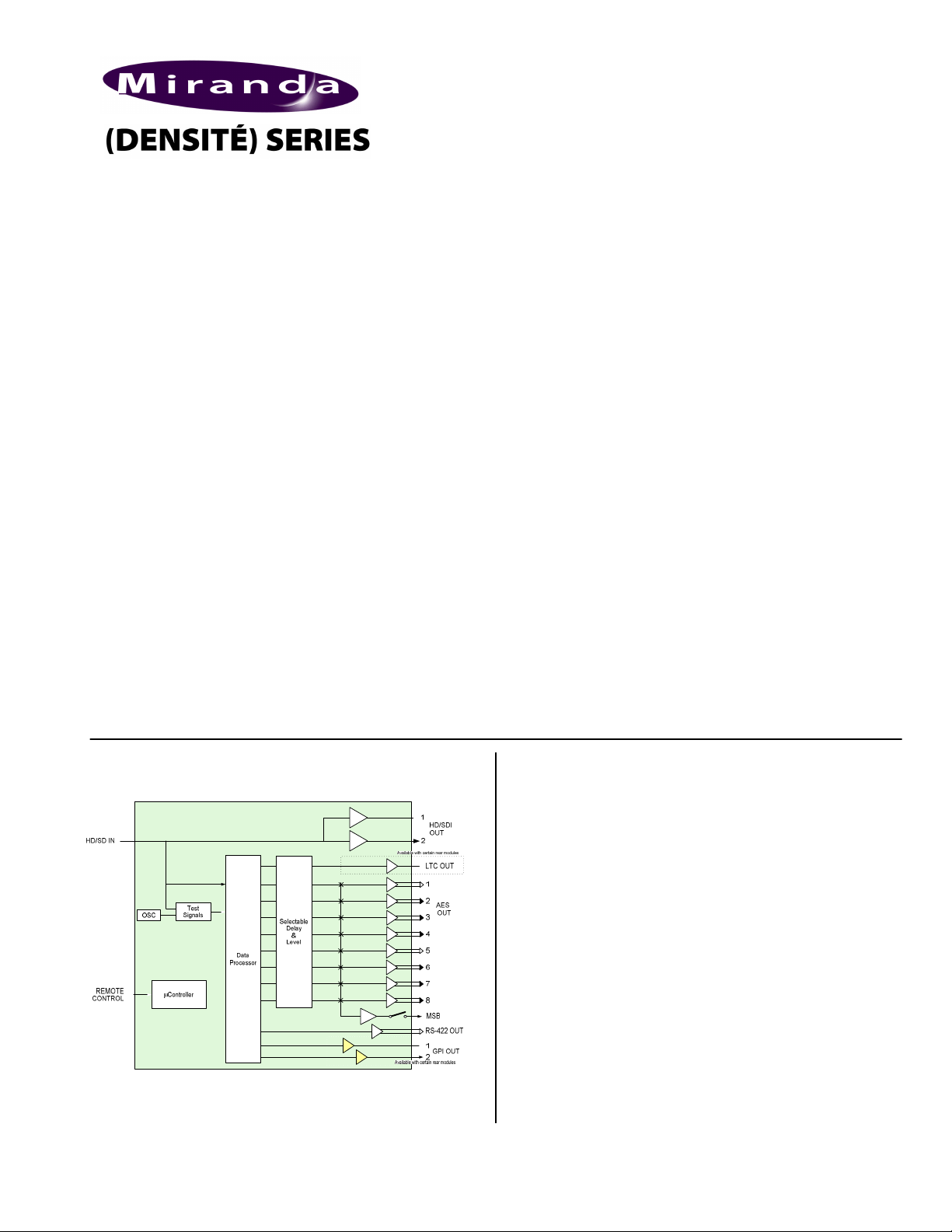
FUNCTIONAL BLOCK DIAGRAM
• Linear Time Code (LTC) output translated from
Ancillary Time Code (ATC) data or Digital Vertical
Interval Time Code (DVITC)
• RS-422 serial data output signal reconstructed from
ANC data inserted by the embedder (including Dolby
metadata)
• Two opto-isolated GPI data output signals
reconstructed from ANC data inserted by the embedder
SPECIFICATIONS
VIDEO INPUT
Video Signal: HD/SD-SDI
SMPTE 292M/SMPTE 259M
(see list of supported formats below)
Embedded audio as per SMPTE
299M/SMPTE 272M
Embedded ATC/DVITC as per
SMPTE RP 188/SMPTE 266M
Embedded RS-422 & GPI as per
SMPTE 291M (with proprietary DID)
Cable Length: up to 110m/250m of Belden 1694A
Return Loss: >15 dB, 5 MHz to 1.5 GHz/270MHz
AUDIO AES-3id OUTPUT
Signal: AES-3id (SMPTE 276M)
Level: 1.0 Vp-p ±10%
Impedance: 75 Ω unbalanced
……(continued)
ADX-1881 Page 1 of 12
Page 2
ADX-1881 HD/SD 8 AES Disembedder
PROCESSING PERFORMANCE
Panel
Guide to Installation and Operation
SPECIFICATIONS(cont’d)
AUDIO AES SIGNAL
Sampling Rate: 48kHz synchronous
LTC SIGNAL OUTPUT
Signal: Reconstructed LTC from ATC/DVITC
Impedance:
Level: 1.0 Vp-p
RS-422 SIGNAL OUTPUT
Signal: RS-422
Rate: Reconstruction of signal input to
GPI SIGNAL OUTPUT (2)
Signal: Opto-isolated, common emitter
Forward voltage 30V max
Reverse voltage 5V max
Rate: DC- to 250 Hz
VIDEO OUTPUT (Input active loop-through)
Video Signal: HD/SD-SDI SMPTE 292M/SMPTE
Return Loss: >15 dB up to 1.5 GHz/270MHz dB
Wideband Jitter: < 0.2 UI p-p
< 55Ω source, unbalanced 1kΩ load
embedder (38,400 or 115,200 bauds)
259M
Signal Path: 10-bit video / 24-bit audio
Audio Processing
Delay:
Audio Delay: Up to 3 video frames (1/2 frame steps)
ATC/DVITC Delay: None, 1, 2,or 3 frames before
RS-422
Processing Delay:
GPI Processing
Delay:
Test Signals: Audio - 1 kHz tone (R steady, L
Power: 9.5 W
Note ‡‡: Applicable to combinations of AMX-1881and ADX1881
List of supported formats:
1920 x 1080/59.94/I
1920 x 1080/50/I
1920 x 1080/29.97/P
1920 x 1080/25/P
1920 x 1080/24/P
1920 x 1080/23.98/P
1920 x 1080/29.97/PsF
(detected as 1920 x1080/59.94/i)
ADX-1881-75-DRP
875 µs (combined embedding and
extraction ‡‡)
translation to LTC
500 µs max. (combined embedding
and extraction ‡‡) (1 frame in
metadata mode)
4 video lines (combined embedding
and extraction ‡‡)
pulsed) -18dBFS (EBU R49, R68)
LTC – 10 second loop starting at
23:59:00:00
1920 x 1080/25/PsF
(detected as 1920 x 1080/50/i)
1920 x 1080/24/PsF
1920 x 1080/23.98/PsF
1280 x 720/59.94/P
1280 x 720/50/P
525 (NTSC)
625 (PAL)
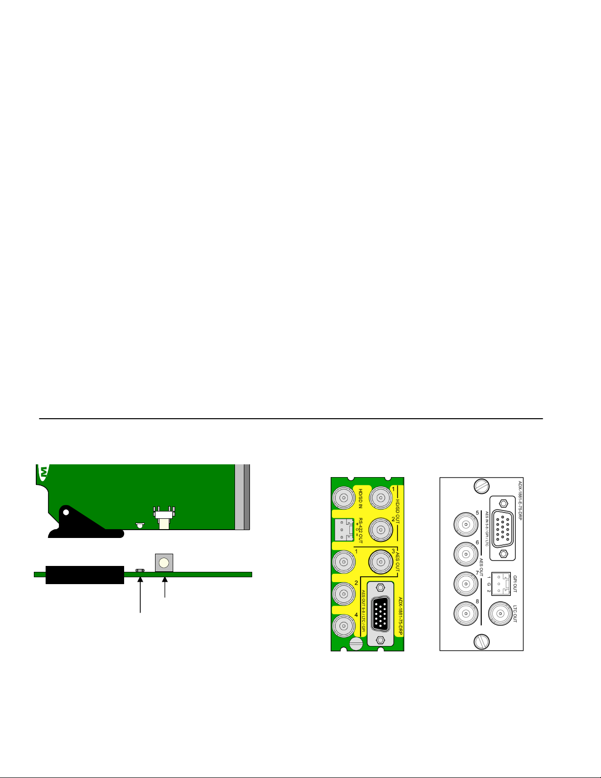
ADX-1881Breakout
ADX-1881
ADX-1881 Front card edge
Page 2 of 12 ADX-1881
Select
Status
SELECT button
Status LED
(Note: female 15-pin connectors on both panels)
ADX-1881 Rear Connector Panels
Page 3
INSTALLATION
Make sure the following items have been shipped with your
ADX-1881. If any of the following items are missing,
contact your distributor or Miranda Technologies Inc.
* ADX-1881 HD/SD 8 AES Disembedder
* ADX-1881-75-DRP rear panel
* ADX-1881 rear panel
* Densite-ext-mount external mounting bracket (one per
frame)
The ADX-1881 and its associated rear connector panel
must be mounted in a DENSITÉ frame. It is not necessary
to switch off the frame’s power when installing or removing
the ADX-1881. See the DENSITÉ Frame manual for
detailed instructions for installing cards and their
associated rear panels.
The ADX-1881 has multiple inputs and outputs, and
making space for all the necessary connectors at the rear
of the frame requires a double-width rear panel.
Overview
The DENSITÉ frame incorporates a central controller card,
located in the center of the frame, which is equipped with
an LCD display and a control panel. The controller handles
error reporting and local and remote control for all cards
installed in the frame. The display and control panel are
assigned to the card in the frame whose SELECT button
has been pushed.
Status Monitor LED
The status monitor LED is located on the front card-edge of
the ADX-1881 module, and is visible through the front
access door of the DENSITÉ frame. This multi-color LED
indicates module status by color, and by flashing/steady
illumination, according to the following chart (which also
indicates fault reporting for this card on the DENSITÉ
frame’s serial and GPI interfaces).
REPORT COLOR (F=flashing)
SERIAL GPI G Y R FR
No errors
No signal
No rear
Test mode
µ : Factory default. User configurable
µ
µ
µ
µ
µ
A “Flashing Yellow” Status LED indicates that the SELECT
button on the front panel has been pushed, and the
controller display and control panel are now assigned to
this card.
ADX-1881 HD/SD 8 AES Disembedder
Guide to Installation and Operation
When a double–width rear panel has been installed, the
ADX-1881 must be installed in the right-most of the two
slots covered by the panel in order to mate with the panel’s
connectors. If it is placed in the wrong slot, the front panel
LED will flash red. Move the card to other slot for correct
operation. No damage will result to the card should this
occur.
In addition, the ADX-1881 requires an external mounting
bracket and breakout panel. The breakout panel is
connected to the rear panel via a multi-conductor cable
fitted with two male connectors. The ADX-1881’s inputs
and outputs occupy both panels.
See the annex at the end of this manual for the
specification of the cable to interconnect the rear panel and
the breakout panel.
The LED color assignments for some error conditions can
be reconfigured by the user (see the chart and menu for
details).
User Interface
Pushing the SELECT button will cause the on-card
STATUS LED to flash yellow, and the card identification
and the current status will be shown on the controller card’s
display. The STATUS LED will revert to it’s normal state
upon a second push of the button, or after a short delay.
The messages which may appear are shown in the top line
of the menu chart on page 3
Example :
SELECT button pushed twice when there is no input
signal connected to the rear panel and the LED is
steady red:
A D X - 1 8 8 1
Use the local control panel to access the detailed status
report shown in the STATUS menu on page 3.
Operating Parameter Adjustment
The ADX-1881 has operating parameters which may be
adjusted at the controller card interface. After pressing the
SELECT button on the ADX-1881 card, use the keys on
the local control panel (described in the Controller card
manual) to step through the displayed menu and adjust the
parameters. The menus are shown below.
A LN O S I G N
ADX-1881 Page 3 of 12
Page 4

ADX-1881 HD/SD 8 AES Disembedder
Guide to Installation and Operation
ADX-1881 Menus
STATUS
USER PRESET
(continued)
NO REAR/ NO SIGNAL/ 720p50/ 720p60/ 720p59.94/ 1080p24/ 1080p24sF/ 1080p23.98/
1080p23.98sF/ 1080p25/ 1080i50/ 1080p29.97/ 1080i59.94/ 625/ 525
AUDIO GROUPS
EMBEDDED TC
EMBEDDED
RS422
EMBEDDED GPI
AES OUT 1
AES OUT 2
AES OUT 3
AES OUT 4
AES OUT 5
AES OUT 6
AES OUT 7
AES OUT 8
NONE / 1234
NONE / PRESENT
NONE / PRESENT
NONE / 12
BITS
MODE
EMPHASIS
USE
ENCODING
Same as AES OUT 1
Same as AES OUT 1
Same as AES OUT 1
Same as AES OUT 1
Same as AES OUT 1
Same as AES OUT 1
Same as AES OUT 1
LOAD
SAVE
[ USER 1, USER 2, USER 3, USER 4, USER 5 ]
[ USER 1, USER 2, USER 3, USER 4, USER 5 ]
16 BIT / 20 BIT / 24 BIT / OTHER
N.I. / 2 CHANNEL / 1 CHANNEL / P/S / STEREO
N.I. / NONE / 50/15-us / J.17
CONSUMER / PROFESSIONAL
LINEAR PCM / NON PCM
Page 4 of 12 ADX-1881
Page 5

ADX-1881 HD/SD 8 AES Disembedder
Guide to Installation and Operation
AES OUTPUT
LTC OUTPUT
[ AUTO, 10, 11, …, 20 ], in 525
RS-422
OUTPUT
(continued)
AES OUT 1-2
AES OUT 3-4
AES OUT 5-6
AES OUT 7-8
AES OUT 1
AES OUT 2
[ GROUP 1, GROUP 2, GROUP 3, GROUP 4 ]
[ GROUP 1, GROUP 2, GROUP 3, GROUP 4 ]
[ GROUP 1, GROUP 2, GROUP 3, GROUP 4 ]
[ GROUP 1, GROUP 2, GROUP 3, GROUP 4 ]
LEVEL
PHASE INVERT
MUTE L&R
SWAP L&R
Same as AES OUT 1
LEFT
RIGHT
LOCK
LEFT
RIGHT
[ OFF, ON ]
[ OFF, ON ]
AES OUT 3
Same as AES OUT 1
AES OUT 4
Same as AES OUT 1
AES OUT 5
Same as AES OUT 1
AES OUT 6
Same as AES OUT 1
AES OUT 7
Same as AES OUT 1
AES OUT 8
Same as AES OUT 1
AES DELAY
FROM
DVITC LINE
DELAY
MODE
METADATA LINE
[ AUTO, 7, 8, …, 22 ], in 625
[ NONE, 0.5 FRAME, 1.0 FRAME, 1.5 FRAME,
2.0 FRAME, 2.5 FRAME, 3.0 FRAME ]
[ FIRST ATC, SECOND ATC ]
[ NONE, 1 FRAME, 2 FRAME, 3 FRAME ]
[ SERIAL, METADATA ]
[ LINE 9, LINE10, …, LINE20 ]
[MUTE, -95.5 dB, ..., 0 dB, ..., 12dB]
[MUTE, -95.5 dB, ..., 0 dB, ..., 12dB]
[ OFF, ON ]
[ OFF, ON ]
[ OFF, ON ]
Half values are not relevant
for progressive format
Only for HD Input
Only for SD Input
ADX-1881 Page 5 of 12
Page 6

ADX-1881 HD/SD 8 AES Disembedder
Guide to Installation and Operation
TEST
CONFIG
ALARM
VERSION
AES OUT 1
AES OUT 2
AES OUT 3
AES OUT 4
AES OUT 5
AES OUT 6
AES OUT 7
AES OUT 8
LTC OUT
[ OFF, TONE ]
[ OFF, TONE ]
[ OFF, TONE ]
[ OFF, TONE ]
[ OFF, TONE ]
[ OFF, TONE ]
[ OFF, TONE ]
[ OFF, TONE ]
[ OFF, LOOP ]
NO SIGNAL
NO LTC
NO AES 1-2
NO AES 3-4
NO AES 5-6
NO AES 7-8
TEST MODE
ADX-1881: xxx
ALARM LEVEL
ALARM REPORT
ALARM LEVEL
ALARM REPORT
ALARM LEVEL
ALARM REPORT
ALARM LEVEL
ALARM REPORT
ALARM LEVEL
ALARM REPORT
ALARM LEVEL
ALARM REPORT
ALARM LEVEL
ALARM REPORT
[ GREEN, YELLOW, RED, FLASH RED ]
[ NONE, GPI ]
[ GREEN, YELLOW, RED, FLASH RED ]
[ NONE, GPI ]
[ GREEN, YELLOW, RED, FLASH RED ]
[ NONE, GPI ]
[ GREEN, YELLOW, RED, FLASH RED ]
[ NONE, GPI ]
[ GREEN, YELLOW, RED, FLASH RED ]
[ NONE, GPI ]
[ GREEN, YELLOW, RED, FLASH RED ]
[ NONE, GPI ]
[ GREEN, YELLOW, RED, FLASH RED ]
[ NONE, GPI ]
Page 6 of 12 ADX-1881
Page 7

FACTORY
DEFAULT
[] Parameter to select
** Press Select pushbutton to activate selection.
Underlined values in the parameter value lists are the
factory default values, and will be applied when factory
default-restore is selected.
USER PRESET menu
LOAD: Selects which predefined parameter settings will be
used by loading a personalized user profile.
SAVE: Saves the parameter settings in one of the five
possible user preset profiles.
AES OUTPUT menu
AES OUT 1-2, AES OUT 3-4, AES OUT 5-6, AES OUT 78: Selects which embedded audio group will appear at the
indicated AES outputs of the ADX-1881.
AES OUT 1, 2, 3, 4, 5 ,6, 7, 8: MUTE; SWAP L&R: Select
ON or OFF for each of the four AES outputs to mute the
output or swap the left and right signals. LEVEL: Sets the
audio gain from -96 dB to +12 dB in 0,5 dB steps. PHASE
INVERT: Select “on”, to invert the selected audio channel
phase.
AES DELAY: Sets the delay of the AES audio as it passes
through the disembedder. Selectable between NONE, and
a number of video frames (0 to 3 frames in ½ frame steps).
LTC OUTPUT menu
FROM: Allows the user to select the source of the time
code appearing at the LTC output as translated from either
the first or second embedded ATC (HD input only).
DVITC LINE: Selects the video line from which the DVITC
is extracted. The extracted DVITC is then translated to LTC
(SD input only).
DELAY: Sets the time code delay when the extracted time
code is translated to LTC. The delay is selectable between
NONE and a number of video frames (1 to 3).
RS-422 OUTPUT menu
MODE: Sets the RS-422 extraction mode:
• Serial – extracts RS-422 serial data
[ RESTORE ]
ADX-1881 HD/SD 8 AES Disembedder
Guide to Installation and Operation
• Metadata – extracts Dolby metadata (RS-422
formatted)
METADATA LINE: When “Metadata” mode is selected,
selects the line from which the Dolby metadata (RS-422) is
extracted
CONFIG TEST menu
AES 1, 2, 3, 4, 5 ,6, 7, 8: the user can enable or disable a
test tone (1 KHz, R-steady, L-pulsed, at –18dBFS) on each
of the four AES outputs individually.
LTC OUT: User can enable a LTC test loop (10 seconds
loop starting at 23:59:00:00).
CONFIG ALARM menu
The user can configure the status LED presentation
(ALARM LEVEL) and fault reporting (NONE or GPI) for
some of the fault conditions of the ADX-1881.
NO SIGNAL: the errors include, no HD/SD-SDI signal
attached to the card input, or faulty incoming HD/SD-SDI
signal.
NO LTC: Indicates that there is no embedded time code
data in the HD/SD-SDI signal.
NO AES 1-2, NO AES 3-4, NO AES 5-6, NO AES 7-8:
Indicates that the selected audio group for the AES outputs
is not present in the HD/SD-SDI signal.
TEST MODE: Indicates whether test signals are present
on any of the ADX-1881 audio outputs or LTC outputs.
FACTORY DEFAULT menu
Select RESTORE to reset all of the menu-adjustable
parameters to a factory-preset state (indicated in the menu
by an underline in the list of available choices).
ADX-1881 Page 7 of 12
Page 8

ADX-1881 HD/SD 8 AES Disembedder
Guide to Installation and Operation
iControl Interface – ADX-1881
The ADX-1881 can be operated using Miranda’s iControl
system. This section describes and explains the control
panel associated with the ADX-1881. Please consult the
iControl User’s Guide for information about setting up and
operating iControl.
In iControl Navigator or iControl Websites, double-click on
the ADX-1881 icon to open the control panel.
There are seven sections in the ADX-1881 iControl panel:
Status Bar: located at the top of the panel, it provides
status icons for several key items and text messages
explaining the detected errors. A complete description of
the Status bar begins on this page.
Select the following tabs by clicking on their name at the
left side of the panel:
Audio: provides controls for disembedding and processing
of audio signals. A complete description of the Audio tab
begins on page this page.
Metadata: gives access to the controls for disembedding
LTC data from the input HD/SD-SDI signal and provides
status on the other data also embedded in the input
HD/SD-SDI signal. A complete description of the Metadata
tab begins on page 9.
Test: gives the option to enable output test signals. A
complete description of the Test tab begins on page 10.
Factory: Allows the user to reset the options to the default
factory-preset settings. A complete description of the
Factory tab begins on page 10.
Info: shows information on the ADX-1881 and allows entry
of some data. A complete description of the Info tab begins
on page 10.
User Presets: Allows the creation of user profiles for a
personalized configuration of the ADX-1881. A complete
description of the User Presets begins on page 11.
Status bar
The status bar provides a continuous update of the status
of the ADX-1881. The status bar includes three sections:
Header
Icons
Message
area
The header gives the product’s name, and identifies the
slot in which it is installed in its Densité frame. At the left is
a status icon whose color shows the overall status of the
ADX-1881:
Green = OK
Yellow = warning
Red = error
The 3 icons monitor specific aspects of the operation of
the ADX-1881. Move the cursor over an icon to see its
current status in the message area below the icons. If
there is an error status, the message will automatically
appear.
• The first icon shows whether the remote control of
this ADX-1881 device is enabled or not.
• The second icon shows the input status. Move the
cursor over the icon to display the video format.
• The third icon indicates if audio or video test signals
are active.
Audio
The Audio tab shows the audio groups detected and
provides resources for managing the audio processing of
the ADX-1881.
Group Detected: indicates embedded audio groups in the
ADX-1881 HD/SD-SDI input.
To configure the AES digital audio signals, access the
AES1 to 4 tabs. There are two sliders (left and right for
Page 8 of 12 ADX-1881
Page 9

stereo sound) available to set the level from -96 dB to +12
dB in steps of 0.5 dB. To invert the selected audio channel
phase, check the Phase Invert boxes. The Lock option
locks both channel level sliders together, so that moving
one slider moves the other one as well. The Mute option
mutes both audio channels completely. The Swap option
interchanges the right and the left audio channels.
ADX-1881 HD/SD 8 AES Disembedder
Guide to Installation and Operation
The Status tab monitors some of the information carried in
the AES outputs channel status.
The Delay tab allows the user to set the delay of the AES
audio as it passes through the disembedder. The delay is
selectable between none, and a number of video frames (0
to 3 frames in 0.5 frame steps).
\
The Disembedding tab allows the user to select which
embedded audio group will appear at the indicated AES
outputs.
The Bits status monitors the audio samples word length (in
bits). The possible values are 16 bits, 20 bits, 24 bits or
other.
The Mode status monitors the channel mode. The possible
values are two channels (Two ch), one channel (One ch),
primary or secondary (Pri/Sec), Stereo or Other. If not
indicated, it will show as N/I.
The Emph status monitors the audio channel emphasis.
The possible values are None, 50/15 µs and J.17. If not
indicated, it will show as N/I.
The Use status monitors the use of channel status block.
The possible values are either professional (PRO) or
consumer (CONS).
The Encoding status monitors the audio channel encoding
type. The possible values are PCM or NPCM (non-PCM).
Metadata
The Metadata tab offers setting options for the output LTC
signal for the embedded time code, RS-422 signal, GP1
and GP2.
The LTC Output window allows the user to select the
source of the time code appearing at the LTC output (ATC,
DVITC). For an HD-SDI input, using the HD ATC Select
drop down menu, select the ATC signal to be disembedded
(first ATC or second ATC).
For an SD-SDI input, using the SD DVITC line drop down
menu, select the desired line to be disembedded. If the
input DVITC is in a 525 format, the available selections will
be auto or lines number 10 to 20. If the input DVITC is in
625 format, the Auto option remains, but the line numbers
vary from 7 to 22.
ADX-1881 Page 9 of 12
Page 10

ADX-1881 HD/SD 8 AES Disembedder
at 23:
59:00:00)
Guide to Installation and Operation
The delay drop down menu allows the user to add delay to
the extracted time code while translated to LTC. The delay
is selectable from none to 3 frames.
The Status tab shows the detection of input embedded
time code, RS-422, GPI 1 and GPI 2 signals. When
present, the status icons turn to green.
The RS-422 tab allows the user to choose whether to
disembed Dolby RS-422 data from the HANC (select
Serial from the pulldown list) or from the VANC (select
Metadata from the pulldown list). When Metadata is
selected, the Metadata Line pulldown becomes active,
allowing the line containing the data to disembed to be
selected (range 9-20)
Enables a test tone (1 KHz,
R-steady, L-pulsed, at-18
dBFS) in each of the eight
AES outputs individually
Enables an output LTC test
loop (10 second loop starting
Factory
Clicking the Load Factory button will restore all of the
adjustable parameters to a factory-preset state. Those
preset settings are indicated by an underline in the ADX-
1881 menus on pages 4 and 5 of this manual.
Info
The Info tab provides information about the ADX-1881,
and provides some data entry fields.
Test
The Test menu allows the user to enable test signals on
the AES and LTC outputs for troubleshooting purposes.
Label and Short label: type a label and a short label for
this device in the appropriate data entry boxes.
Source ID: enter the source ID
The Details button gives additional information about the
device. The manufacturing process, firmware version,
service version and panel version can be found there.
Page 10 of 12 ADX-1881
Page 11

The Advanced button shows the long ID of the device. The
Miranda Long ID is the address of this ADX-1881 in the
iControl network.
The Remote system administration button shows the
“joining locators: ADX-1881” window.
User presets
The ADX-1881 has memory registers which can hold up to
5 user-defined parameter settings.
ADX-1881 HD/SD 8 AES Disembedder
Guide to Installation and Operation
Select any one of the five presets using the pull-down list.
The name of the currently-selected user preset is shown on
the name bar.
• Click Load to load the contents of the selected user
preset into the ADX-1881. All parameter settings and
values will be replaced by the contents of the selected
user preset.
• Click Save to store the current parameter settings and
values from the ADX-1881 into the selected user
preset. The existing contents of the preset will be
overwritten.
ANNEX – Connecting Cable Specification
This cable joins the ADX-1881 rear panel to the ADX-1881 breakout panel
ADX-1881 Page 11 of 12
Page 12

ADX-1881 HD/SD 8 AES Disembedder
Guide to Installation and Operation
COMPLIANCE
This unit generates, uses, and can radiate radio frequency energy. If the unit is not properly installed and used in accordance
with this guide, it may cause interference with radio communications. Operation with non-certified peripheral devices is likely to
result in interference with radio and television reception. This equipment has been tested and complies with the limits in
accordance with the specifications in:
FCC Part 15, Subpart B; CE EN50081-1:1992; CE EN50082-1:1992.
CONTACT MIRANDA
For technical assistance, please contact the Miranda Technical support centre nearest you:
Americas
Telephone:
+1-800-224-7882
e-mail:
techsupp@miranda.com
Visit our web site at www.miranda.com
Asia
Telephone:
+81-3-5730-2987
e-mail:
asiatech@miranda.com
Radio Frequency Interference and Immunity
Europe, Middle East, Africa, UK
Telephone:
+44 (0) 1491 820222
e-mail:
eurotech@miranda.com
France (only)
Telephone:
+33 (0) 1 55 86 87 88
e-mail:
francetech@miranda.com
Page 12 of 12 ADX-1881
 Loading...