

Page 1

3000
User Manual
Page 2

Notices & Warranties
Copyright Regulations
It is illegal for anyone to violate any of the rights provided by the copyright laws to the owner of copyright,
except for fair use (mainly private noncommercial use). Also, in certain cases copying is prohibited with
no exceptions. In no event shall Canopus be liable for any direct or indirect damages whatsoever arising
from the use of captured materials.
Warranty
Your ADVC3000 options are covered by a limited warranty when you register your Canopus product. This
warranty is for a period of one year (or two years in European Union countories) from the date of purchase
from Canopus or an authorized Canopus agent. This warranty applies only to the original purchaser of the
Canopus product and is not transferable. Canopus Co., Ltd. warrants that for this period the product will
be in good working order. Should our product fail to be in good working order, Canopus will, at its option,
repair or replace it at no additional charge, provided that the product has not been subjected to misuse,
abuse or non-Canopus authorized alternations, modifications and/or repair. Proof of purchase is required
to validate your warranty.
Canopus is not responsible for any lost profits, lost savings or other incidental or consequential damages
arising out of the use of, or inability to use, this product. This includes damage to property and, to the
extent permitted by law, damages for personal injury. This warranty is in lieu of all other warranties of
merchantability and fitness for a particular purpose.
Cautions
Please observe the following cautions when using this product. If you have any questions regarding the
method of usage, the descriptions herein, or any other concerns, please contact Canopus Technical
Support.
2
4
Page 3

Notices & Warranties
DANGER
The following conditions indicate the potential for serious bodily injury or loss of life.
Health precautions
In rare cases, fl ashing lights or stimulation from the bright light of a computer display or TV monitor may
trigger temporary epileptic seizures or loss of consciousness. It is believed that even individuals who have
never experienced such symptoms may be susceptible. If you or close relatives have experienced any of
these symptoms, consult a doctor before using this product.
Do not use in environments requiring a high degree of reliability and safety
This product is not to be used in medical devices or life support systems. The characteristics of this
product is not suited for use with such systems.
Protect against static electricity
An electrostatic discharge may damage components of this product. Do not directly touch any of the
connectors.
Static electricity can be generated on clothing and on people. Before handling the product, discharge
static electricity from your body by touching a grounded metal surface.
Do not disassemble
Do not remove the cover or modify the Product. Fire, electric shock or malfunction may result. For internal
inspection or repair, please contact your system integrator or Canopus directly.
Do not operate at other than the specifi ed voltage
Do not operate at other than the specifi ed voltages of AC 100-240V. Operation at other than the rated
voltage may result in fi re or malfunction.
Do not operate with other than the specifi ed power supply
Do not operate with other than the specifi ed power cord, or with a car power supply. Such operation may
result in fi re or malfunction.
Handle the power cord carefully
Do not place heavy objects on top of the cord, or place it near hot objects. Doing so may damage the cord
and result in fi re, electrical shock, or malfunction. Altering the cord, or excessively bending or pulling the
cord may result in fi re or electrical shock. If the cord is damaged, please contact your local retail outlet or
Canopus directly.
3
5
Page 4

Notices & Warranties
CAUTION
The following conditions indicate the potential for bodily harm, damage to hardware or loss of data.
Do not pull the power cord when disconnecting from electrical outlet
When disconnecting the power cord, pull on the plug, not the cord itself. Pulling on the cord can damage
the cord and may result in fi re or electric shock.
Do not touch the power cord with wet hands
Do not disconnect or plug in the power cord when your hands are wet. Contact with water may result in
electric shock, fi re or damage.
Do not setup in areas subject to heat
Do not setup in an area exposed to direct sunlight or near a heating apparatus. The heat can accumulate,
causing burns, fi re or damage. Also, the unit may become deformed or change color.
Only setup using the prescribed method
Do not setup in a manner other than prescribed. Do not use while wrapped in cloth or plastic. Heat can
accumulate, causing burns, fi re or damage.
If product will not be used for an extended period
If this product will not be used for an extended period of time, disconnect the power cord from the electrical
outlet.
Do not block the ventilation holes
Do not use the ADVC3000 covered with a cloth or in an ill-ventilated room.
Covering the vent may cause heat inside of the product resulting in fi re or product malfunction.
Confi rm the enough space around the ventilation holes when mounting this unit on a rack.
Precautions for use of the power cord
The supplied power cord are for exclusive use of this product. Do not operate the product with other power
cord or in other combinations.
4
6
Page 5

Notices & Warranties
FCC Notice
This equipment has been tested and found to comply with the limits for a Class A digital device, pursuant
to Part 15 of the FCC Rules. These limits are designed to provide reasonable protection against harmful
interference when the equipment is operated in a commercial environment. This equipment generates,
uses, and can radiate radio frequency energy and, if not installed and used in accordance with the
instruction manual, may cause harmful interference to radio communications. Operation of this equipment
in a residential area is likely to cause harmful interference in which case the user will be required to correct
the interference at his own expense.
CE Notice
WARNING
This is a class A product. In a domestic environment this product may cause radio interference in which
case the user may be required to take adequate measures.
Declaration of Conformity
According to FCC Part 15
Responsible Party Name: Canopus Corporation
Address: 711 Charcot Avenue San Jose, CA 95131
Telephone: 408-954-4500
Declares that product Model: ADVC3000
Complies with Part 15 of the FCC Rules.
5
7
Page 6

Notices & Warranties
Product Notes
1. Unauthorized copying of a portion or the entirety of this product is prohibited.
2. The description and specifi cations of this product are subject to future change without notice.
3. The description of this product has been prepared to be as complete as possible.
If the reader is aware of any questionable points, errors, or omissions, please contact Canopus.
4. The company assumes no liability for the results of practical application, regardless of item (3)
above.
5. Regardless of whether negligence occurs during usage, the company assumes no liability, even if
there is a claim for extraordinary, incidental or derivative loss, including the loss of profi ts, that arises
during practical application of this product.
6. The analysis, reverse engineering, recompiling and disassembling of the software, hardware or manuals
that accompany this product, and all other related products including miscellaneous supplemental
items, are prohibited.
7. Canopus, as written in both English and Japanese, and its logo are registered trademarks of Canopus
Co., Ltd.
8. ADVC is registered trademark of Canopus Co., Ltd.
9. Microsoft and Windows are registered trademarks of Microsoft Corporation in the US and other
countries.
10. Macintosh is registered trademark of Apple Computer, Inc.
11. Other product names and related items are trademarks or registered trademarks of their respective
companies.
About the Documentation
This document is the ADVC3000 User Manual.
Information not listed in this document may be listed elsewhere.
In cases where there is a difference between a description in this document and an actual operation
method, the actual operation method takes precedence.
6
8
Page 7

3000
Table of Contents
7
9
Page 8

Table of Contents
Table of Contents
Copyright Regulations .............................................................................................................2
Warranty ..................................................................................................................................2
Cautions ..................................................................................................................................2
DANGER .................................................................................................................................3
CAUTION ................................................................................................................................4
FCC Notice .............................................................................................................................. 5
CE Notice ................................................................................................................................ 5
Declaration of Conformity ........................................................................................................ 5
Product Notes ..........................................................................................................................6
About the Documentation ........................................................................................................6
Chapter 1 - Introduction
1 Introduction ......................................................................................................10
1-1. Package contents ............................................................................................................10
1-2. Customer Support ...........................................................................................................11
1-3. Canopus web-site ............................................................................................................11
1-4. Online user registration ...................................................................................................11
1-5. Limitations .......................................................................................................................11
2 Features of ADVC3000 ....................................................................................11
Chapter 2 - Basic Operations
1 Part names and functions ...............................................................................14
1-1. ADVC3000 front panel ..................................................................................................... 14
1-2. ADVC3000 rear panel .....................................................................................................16
1-3. DIP switch settings ..........................................................................................................18
1-4. LCD screen displays .......................................................................................................19
2 Connecting devices .........................................................................................26
2-1. Connecting ADVC3000 unit ............................................................................................. 26
2-2. Importing VCR data to your PC ....................................................................................... 28
2-3. Recording PC-edited data onto a tape with VCR ............................................................29
3 Menu setting operations .................................................................................30
3-1. Menu screen operations ..................................................................................................30
3-2. Presetting the video/audio input ...................................................................................... 33
3-3. Setting parameters .......................................................................................................... 36
Chapter 3 - Appendix
1 Specifi cations ..................................................................................................64
8
10
Page 9

3000
Chapter 1
Introduction
This chapter introduces topics you should know
prior to setting up the ADVC3000. Before you
using the ADVC3000, read this chapter to ensure
a trouble-free setup.
- Introduction
- Features of ADVC3000
11
9
Page 10
Chapter 1 - Introduction
ψ
ψ
1 Introduction
1-1. Package contents
Please verify that the following items are included in the ADVC3000 package. If any of the components
are missing, please contact Canopus Customer Support.
• 1 x ADVC3000 unit
• 1 x Power cord
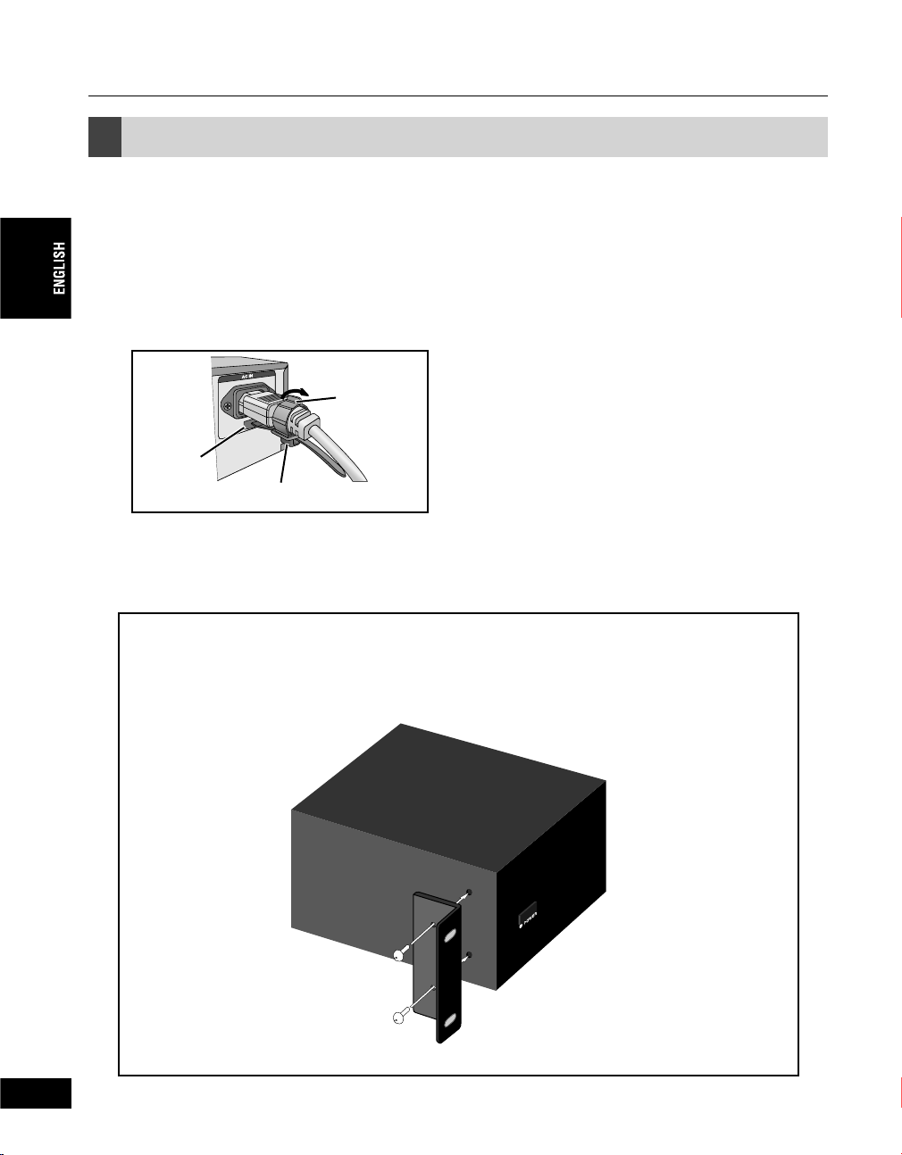
• 1 x Power cord clamp
(to prevent the power cord from accidentally pulling out)
3. Snap
close.
1. Insert.
2. Adjust the position.
• 1 x DV cable [6 pin - 4 pin]
• 2 x Rack-mount brackets
• 4 x Attachment screws
• 1 x ADVC3000 User Manual (this document)
10
12
When mounting the ADVC3000 on a rack:
1. Use a Phillips-head screwdriver to remove the four rubber feet from the bottom of
the unit.
2. Attach the rack-mount bracket to the ADVC3000 unit with the screws provided.
Page 11

Chapter 1 - Introduction
1-2. Customer Support
For questions regarding hardware setup and usage, please contact your local Canopus offi ce,
distributor, or the store where you have purchased this product.
1-3. Canopus web-site
Including ADVC3000, the latest company information is announced at our website
http://www.canopus.com/. The latest drivers, utilities, product manuals, FAQs, etc. are also available
at our website.
1-4. Online user registration
You can register your ADVC3000 at the Canopus website.
http://www.canopus.com/support/supportcenter.php
1-5. Limitations
• Limitations on the nonstandard signal
While the ADVC3000 can convert the signals output by game consoles, there is a possibility that
some software will be unable to synchronize some video and audio signals.
* In order to capture the nonstandard signal, such as one from a game console without audio noise, enable the “108
DVout frame sync”. In this instance, frame-skip or frame-hold will occur.
• Limitations on the ADVC3000 connection
Before you connect(or disconnect) your ADVC3000 to(or from) a PC, ensure that the PC has been
powered off.
• Limitations on connecting your ADVC3000 to Windows 2000 PC through IEEE1394
interface (OHCI)
When the ADVC3000 is operating in NTSC mode, the DV frame rate being output from the OHCI
driver is markedly slower than the standard frame rate. Therefore, glitches in both the frame hold
and time-code can occur regularly while the DV output signal is being converted to an analog
signal. This phenomenon does not occur, however, when the signal is input through OHCI from the
ADVC3000.
2 Features of ADVC3000
High-specifi cation video converter for professional use
The ADVC3000 is a converter designed to be used with professional VCR to convert Analog
Component/SD-SDI to DV and vice versa. This unit enables the conversion of the data from
Betacam, Digital Betacam, etc., to DV for use with nonlinear editing systems. Uncompressed 4:2:2
is used for Component-SDI conversion.
(Continued on the next page)
11
13
Page 12
Chapter 1 - Introduction
(Continued)
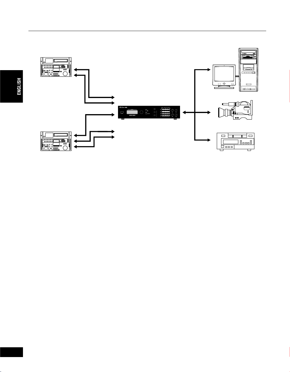
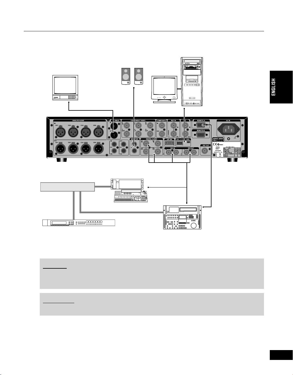
ADVC3000 connection example
VCR with
SD-SDI
input/output
RS-422
SD component
video
SD-SDI
Balanced audio
RS-422
ADVC3000
24'5'6
5&+#0#.1)→&8
5&+
8+&'1+0
&8→5&+#0#.1)
%1/210'06
%1/215+6'
58+&'1
5&+
#7&+1+0
#'5'$7
$#.#0%'&
Engineered by Canopus
70$#.#0%'&
IEEE 1394
#0#.1)#7&+1
+0276.'8'.
PC
DV camera
Betacam
DV/DVCAM deck
DV to RS-422A conversion-driven VCR control
The ADVC3000 features DV to RS-422A conversion-driven VCR control. Its Perfect Sync
technology (patent pending) results in precise synchronization without frame skipping. Using DV
editing software, the ADVC3000 can import data from a wide range of professional VCRs. With two
systems of input/output terminals, the integrated system connecting the Betacam and the Digital
Betacam simultaneously can be established.
Professional specifi cations adaptable to a variety of studio uses
Equipped with TC input/output, ADVC3000 can perform conversion using LTC, DVITC and DV time
code in any direction. ADVC3000 is compatible with 4ch audio and can realize the conversion of
the balanced audio, embedded audio, AES, EBU and DV in any direction. ADVC3000 also has a
Sync Generator (Black Burst output) function, thus it can be introduced to a variety of studio/video
systems.
Easy-to-use input source switching
With control buttons for switching the input source and peak meters on the easy-to-access front
panel, ADVC3000 enables easy settings with the help of the LCD display.
High audio/video synchronism: “Locked Audio”
The ADVC3000 uses a “locked audio function” to digitize the audio signal by synchronizing it
precisely with the speed of the video signal. This function enables the easy conversion of long
duration content.
Versatility with NTSC/PAL
As well as NTSC, which is the format used in Japan and US, PAL format, which is more common
in European and other countries, can also be selected.
*NTSC-PAL (SECAM) cannot be converted.
2U rack-mount size
The ADVC3000, as a 19-inch 2U rack mountable unit, to EIA standard, includes full specifi cations
in a compact body. In addition, the ADVC3000, a stand-alone unit, does not need a PC.
*The rack-mount bracket and the screws are provided with the unit.
12
14
Page 13

3000
Chapter 2
Basic Operations
This chapter explains the basics of the ADVC3000,
such as part names, functions, etc.
- Part names and functions
- Connecting devices
- Menu setting operations
15
13
Page 14
Chapter 2 - Basic Operations
1 Part names and functions
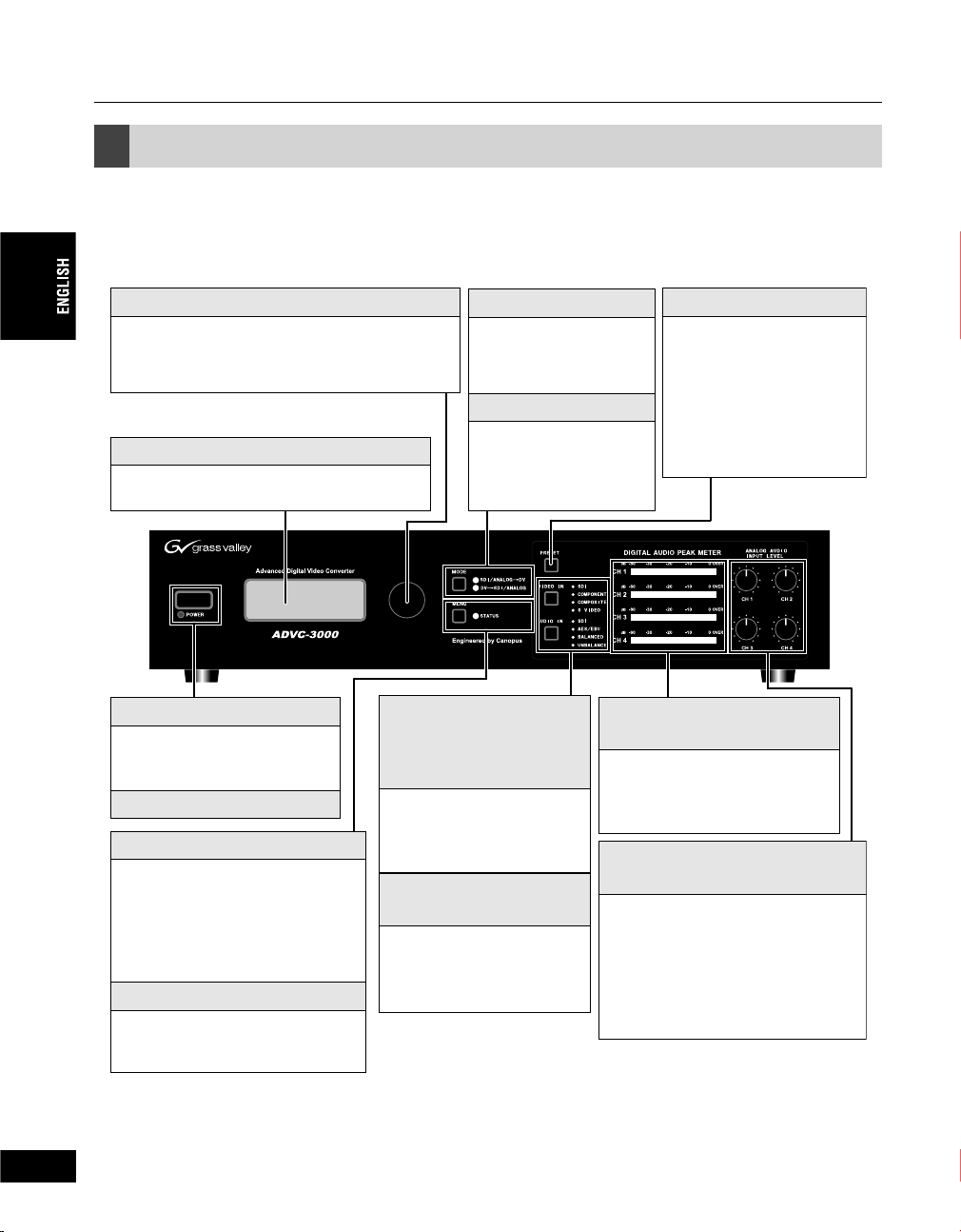
1-1. ADVC3000 front panel
The front panel of the ADVC3000 unit has the following controllers and indicators.
Select dial
Turn the Select dial to choose the menu items, and
press it to confrim.
LCD
Displays input/output status and setting menu.
POWER switch
Turn the ADVC3000 unit on and
off.
Video input select button
[VIDEO IN]
Audio input select button
[AUDIO IN]
POWER LED
Chooses the video and audio
input format.
MENU button
Switches between Main screen and
Menu screen.
In sub-menu, press this button to
return to the main menu.
Video input indicator
Audio input indicator
Displays the video and audio
input format currently chosen.
MODE button
Refer to page 15 for
details.
MODE indicator
Displays the currently
selected operation mode.
Audio level meter
[DIGITAL AUDIO PEAK METER]
Audio Input level dial (CH1 to CH4)
[ANALOG AUDIO INPUT LEVEL]
Adjusts the analog audio level input to
CH1 to CH4.
Turn clockwise to increase the input
level.
PRESET button
Each time you press the
button, preset 1 to 4 is
recalled. (Refer to page 33
for details.)
Displays the peak level of the
audio currently output.
14
STATUS LED
Refer to page 15 for details.
*The position of the average audio level is where the dial
clicks when you turn it.
16
Page 15
Chapter 2 - Basic Operations
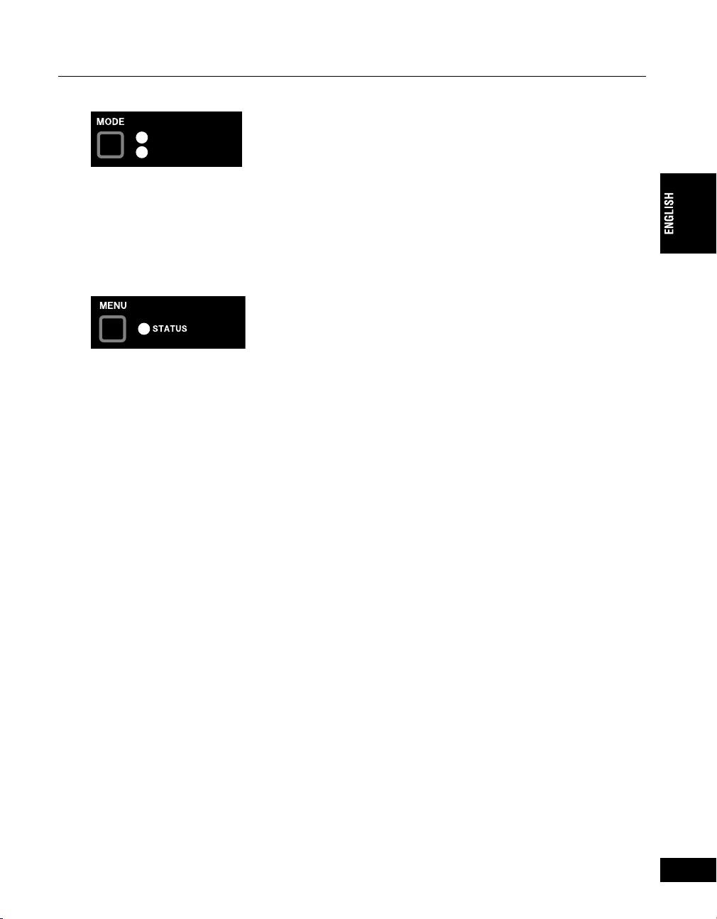
• MODE button
5&+#0#.1)ă&8
&8ă5&+#0#.1)
Used to switch on the operation mode of the ADVC3000. Pressing the button will activate the
Encode operation and Decode operation alternately.
When “SDI/ANALOG DV” LED illuminates, ADVC3000 converts input SDI or analog signal to DV
signal (DV Encode). When “DV SDI/ANALOG” LED illuminates, it converts input DV signal to SDI
signal and analog signal (DV Decode).
• STATUS LED
Displays the following status.
Off: .................... 9-pin remote control is disabled.
Lit green: .......... 9-pin remote control is enabled.
Lit red: .............. 9-pin remote control has been set to enabled, but remote control is prevented by
a communication error. Check that the 9-pin remote cable is correctly connected,
that the connected device’s power is ON, and that the remote control setting has
been enabled on the connected device.
Flashing red: ... A major ADVC3000 operation error has occurred, or several signals required
for operation can’t be detected. Check the error status display screen. Input the
required signals correctly or change the settings for ADVC3000.
* For more information on error status, see “Error status screen” (p.25).
15
17
Page 16
Chapter 2 - Basic Operations
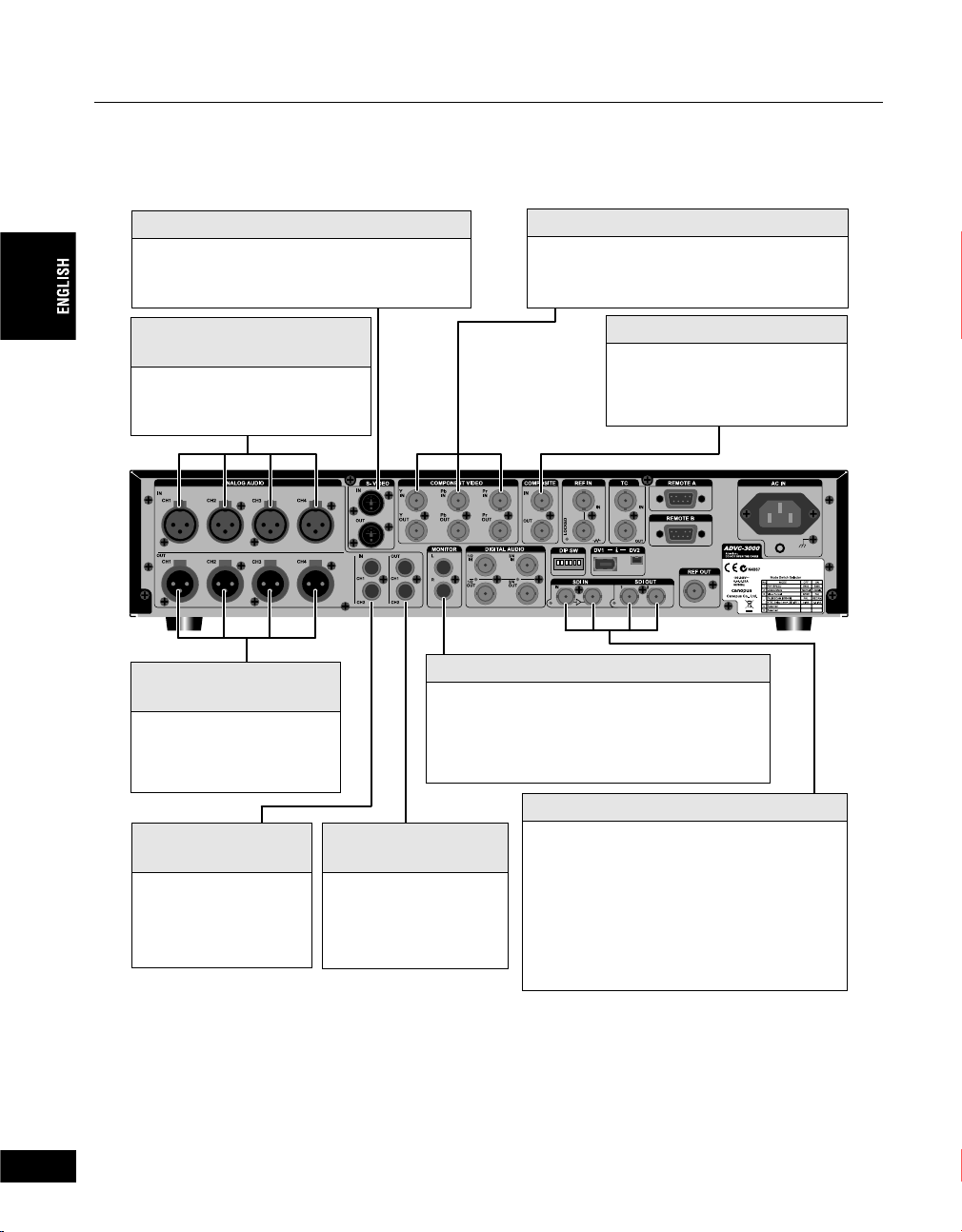
1-2. ADVC3000 rear panel
The rear panel of the ADVC3000 has the following connectors.
S-VIDEO
Input and output connectors for S-Video signal.
ANALOG AUDIO IN
(Balanced input)
Input connectors for balanced
audio signal.
ANALOG AUDIO OUT
(Balanced output)
Output connectors for
balanced audio signal.
COMPONENT VIDEO
Input and output connectors for
component video signal.
COMPOSITE
Input and output connectors for
composite video signal.
MONITOR
Output connectors for the monitor and speakers.
CH1 to CH4 audio can be chosen to be mixed and
output to L and R.
16
18
ANALOG AUDIO IN
(Unbalanced input)
Input connectors for
unbalanced audio signal.
ANALOG AUDIO OUT
(Unbalanced output)
Output connectors for
unbalanced audio signal.
SDI IN/OUT
Input and output connectors for digial video and
embedded audio signals. When SDI input is
detected, the LED next to the SDI input
connector lights red. During SDI output, the LED
next to the SDI output connector lights red.
Page 17
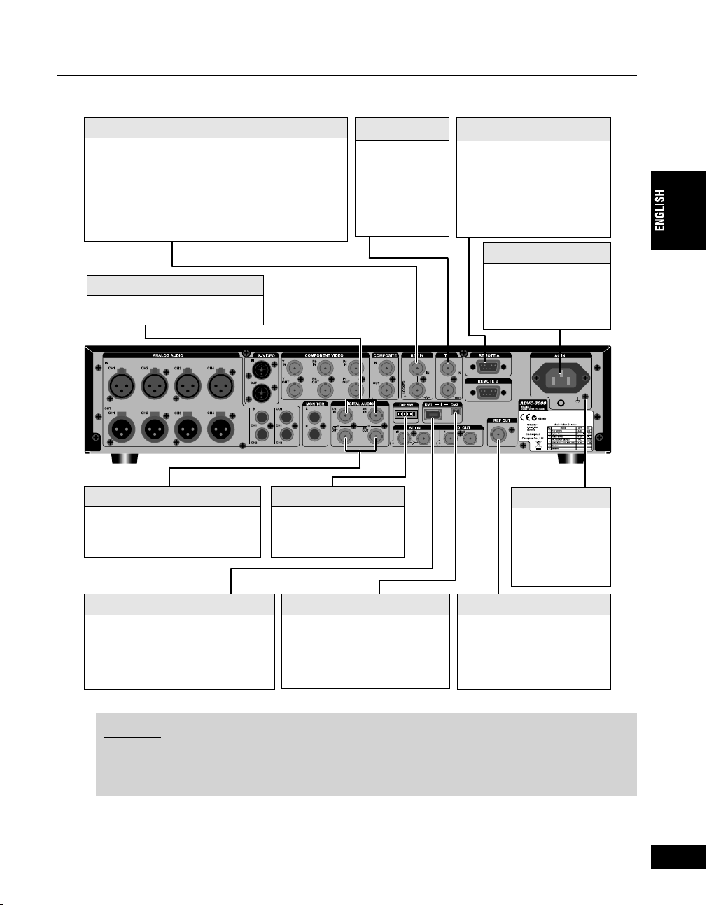
Chapter 2 - Basic Operations
REF IN
Input connectors for receiving a reference signal
(sync signal).The LED lights red when reference
signal is detected and external sync setting is REF IN.
The REF connector has through output. If a cable is
not connected to the output connector, it has a 75 j
automatic terminaltion.
DIGITAL AUDIO IN
Digital audio input connectors.
DIGITAL AUDIO OUT
Digital audio output connectors.
DIP switch
Refer to page 18 for
details.
TC
Time code input
and output
connectors.
REMOTE A/B
Remote control connector.
Select “REMOTE A” or
“REMOTE B” from the
menu.
AC IN
Connect the provided
power cord and then fix it
with the provided power
cord clamp (refer to
page10).
Earth terminal
Connect an earth
wire to this terminal,
if necessary.
DV1 (6-pin)
Use a DV cable to connect the
ADVC3000 to a DV device or a PC.
(Bus power is not supplied.)
DV2 (4-pin)
Use a DV cable to connect the
ADVC3000 to a DV device or a
PC.
REF OUT
Output connector for reference
signal (sync signal).
NOTES
- This unit will not work as an OHCI Hub with Canopus DV products.
- To use this unit as a Hub with OHCI devices, the application also needs to support two or more
devices.
17
19
Page 18
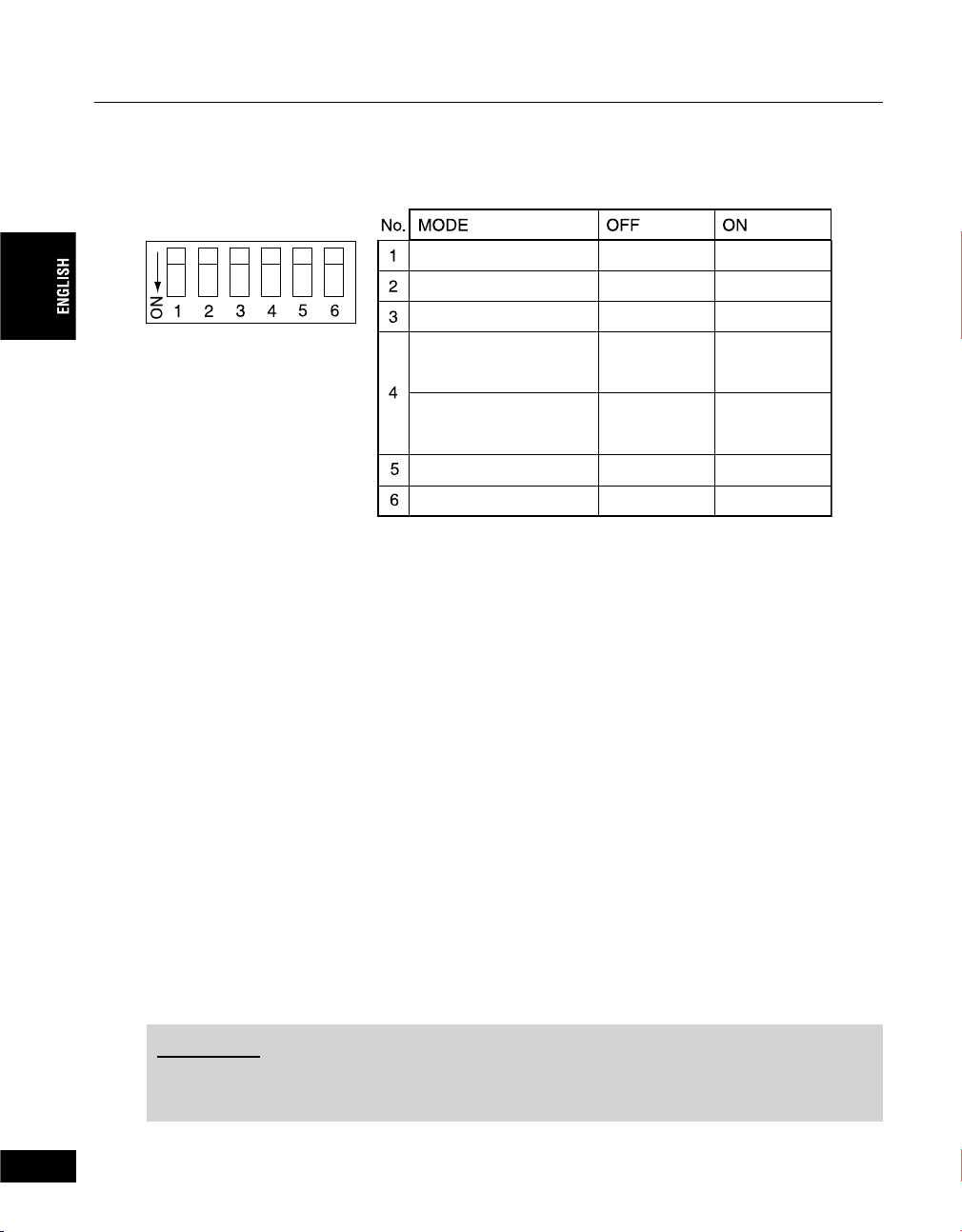
Chapter 2 - Basic Operations
1-3. DIP switch settings
The rear panel of the ADVC3000 unit has the following DIP switches. Default SW3, SW4 settings may
differ depending on the place of purchase.
PHY SPEED
Update Mode
Video Format
PAL/SECAM
(When SW3 is set to ON)
NTSC Setup Level
(When SW3 is set to OFF)
S400
Normal
NTSC
PA L
0 IRE
Reserved
Reserved
• SW1: PHY Speed
Designates the PHY speed.
OFF: S400 ON: S200
• SW2: Update Mode
Used to update the internal software.
(Set this switch to the OFF position for normal operations.)
OFF: Normal ON: Update
• SW3: Video Format
Designates the video signal format.
* Enabled only when the setting in the menu option “107 video standard” is “set by DIP switch”.
OFF: NTSC ON: PAL
• SW4: PAL/SECAM (When SW3 is set to ON)
* Enabled only when the setting in the menu option “107 video standard” is “set by DIP switch”.
OFF: PAL ON: SECAM
: NTSC Setup Level (When SW3 is set to OFF)
* Enabled only when the setting in the menu option “107 video standard” is “set by DIP switch”.
OFF: 0 IRE ON: 7.5 IRE
• SW5: Reserved
Not used. (Set this switch to the OFF position for normal operations.)
• SW6: Reserved
Not used. (Set this switch to the OFF position for normal operations.)
S200
Update
PA L
SECAM
7.5 IRE
18
CAUTION
• Turn off the power of ADVC3000 unit before making any changes for DIP switch settings.
• DIP switches 5 and 6 should be set to OFF. Otherwise, malfunction may occur.
20
Page 19
Chapter 2 - Basic Operations
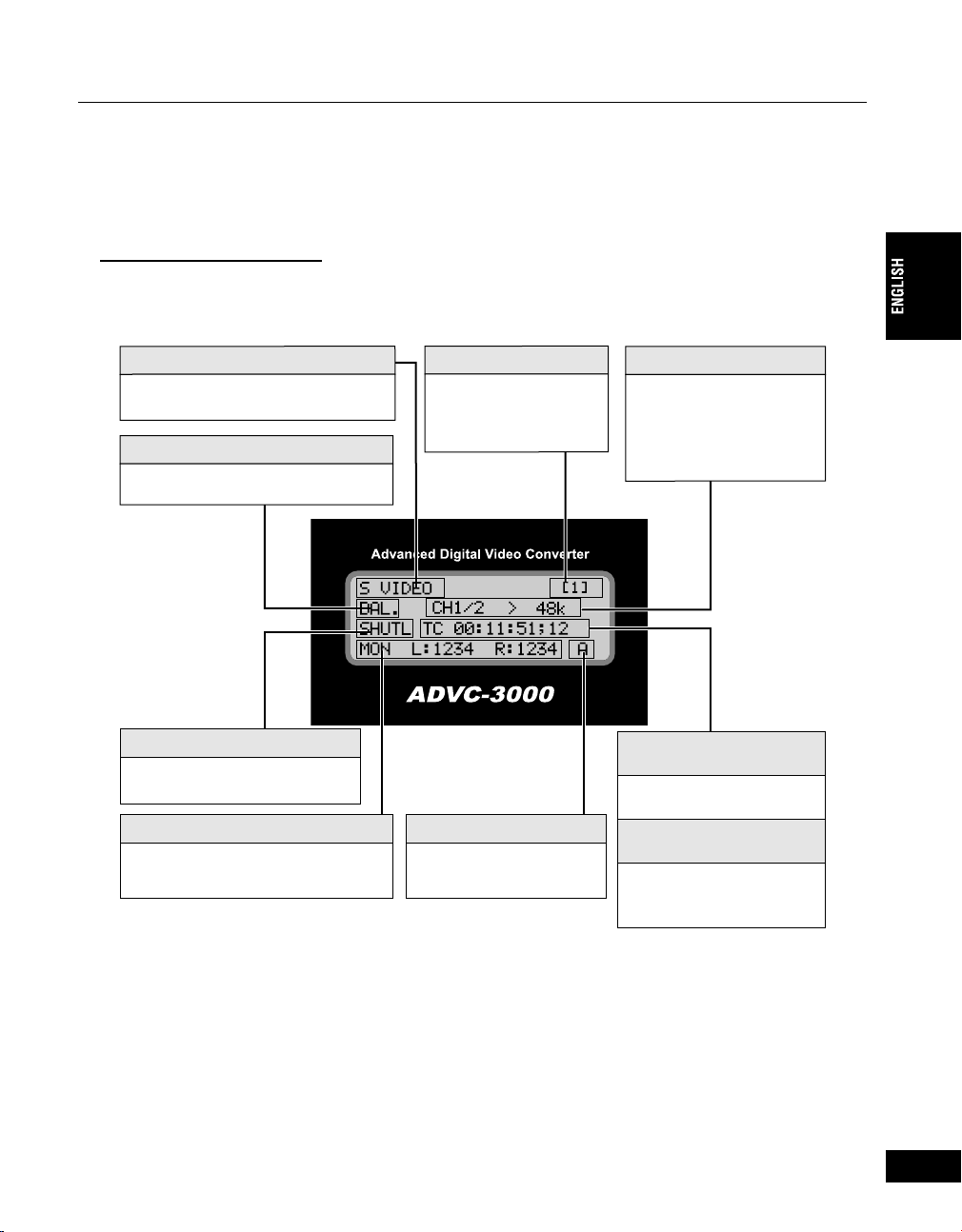
1-4. LCD screen displays
ADVC3000 has three main screens and an error status screen. Turn the Select dial to switch between
the main screens and the error status screen. Pressing the MENU button displays the setting menu
screen.
Main screens 1 and 2
Main screens 1 and 2 differ from each other only in the right portion of the third line (Item 6, below).
This screen shows the current status of the operation.
• In the SDI/ANALOG DV mode
1. Video Input
Displays the video source.
3. Audio Input
Displays the audio status.
5. Deck status
Displays the status of the deck.
7. Audio monitor status
Displays the audio input on each
monitor.
2. Preset status
Displays the preset status
of video/audio input.
(Refer to page 33 for
details.)
8. 9-pin remote control
Displays the remote
control connector in use.
4. Audio format
Displays input channel
and DV encode sampling
frequency.
6. On the Main screen 1:
Input time code
Displays the time code.
6. On the Main screen 2:
Users bit
Displays the number
designated by the user for
identifying each tape.
(Continued on the next page)
19
21
Page 20

Chapter 2 - Basic Operations
(Continued)
1. Video input
SDI ..............................Signal from the SDI connector is input.
COMPONENT ............Signal from the component connector is input.
S VIDEO .....................Signal from the S-Video connector is input.
COMPOSITE ..............Signal from the composite connector is input.
SG ...............................Color bar is output.
2. Preset status
Displays the preset status of video/audio input.
(Refer to page 33 for how to store and recall the settings.)
[1] ................................Preset 1 is selected.
[2] ................................Preset 2 is selected.
[3] ................................Preset 3 is selected.
[4] ................................Preset 4 is selected.
[-] .................................Setting other than preset 1 to 4 is selected.
3. Audio input
SDI ..............................Signal from the SDI input connector is input.
AES .............................Signal from the digital audio input connector is input.
BAL. ............................Signal from the balanced audio input connector is input.
UNBAL. .......................Signal from the unbalanced audio input connector is input.
SG ...............................1kHz test audio is output.
4. Audio format
CH 1-4 > 32 k..............Converts the input audio signal CH1 to 4 to 32kHz, 12bit, 4ch audio.
CH 1/2 > 48 k ..............Converts the input audio signal CH1 and 2 to 48kHz, 16bit, 2ch audio.
CH 3/4 > 48 k ..............Converts the input audio signal CH3 and 4 to 48kHz, 16bit, 2ch audio.
20
5. Deck status
If blank ........................9-pin remote control is not in use.
NoDev .........................Can’t fi nd deck. Check cable connection.
PLAY ...........................Deck is playing.
PLAY* ..........................Deck is playing. (SERVO LOCK)
REC ............................Deck is recording.
REC* ...........................Deck is recording. (SERVO LOCK)
F.FWD .........................Deck is fast-forwarding.
REW ...........................Deck is rewinding.
STOP ..........................Deck is stopped.
PAUSE ........................Deck is shuttling. (Paused)
SHUTL ........................Deck is shuttling.
EJECT ........................No tape in deck.
22
Page 21

Chapter 2 - Basic Operations
6. On the Main screen 1: Input time code
TC 00:00:03:22 ...........For PAL/NTSC NDF (Non Drop Frame)
* A colon is used between seconds and frames as a delimiter.
TC 00:00:03;22 ...........For NTSC DF (Drop Frame)
* A semicolon is used between seconds and frames as a delimiter.
TC --:--:--:-- .................No DV signal output.
* Free-run time code is used during built-in color bar output or when time code is not
input.
” is displayed if the time code set by “301 TC source” cannot be found.
* “T
On the Main screen 2: Users bit
UB 00 00 00 00 ...........The letters or numbers designated by the user are displayed.
UB -- -- -- -- .................No DV signal is output.
* “U” is displayed if the users bit cannot be found.
7. Audio monitor status
----- ..............................The channel is not monitored.
8. 9-pin remote system
A .................................REMOTE A is selected.
B .................................REMOTE B is selected.
If blank ........................The remote connectors are disabled.
23
21
Page 22
Chapter 2 - Basic Operations
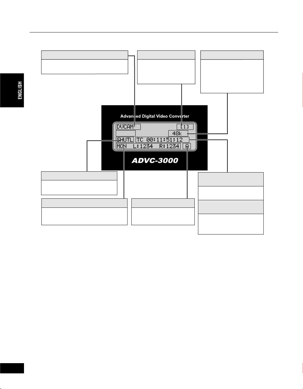
• In the DV SDI/ANALOG mode
1. DV Input
Displays the video source.
4. Deck status
Displays the status of the deck.
6. Audio monitor status
Displays the audio input on each
monitor.
2. Preset status
Displays the preset status
of video/audio input.
(Refer to page 33 for
details.)
7. 9-pin remote control
Displays the remote
control connector in use.
3. Audio format
Displays audio sampling
frequency.
5. On the Main screen 1:
Input time code
Displays the time code.
5. On the Main screen 2:
Users bit
Displays the number
designated by the user for
identifying each tape.
22
1. Video input
DVCAM .......................DVCAM signal is input.
DV ...............................DV signal is input.
SG ...............................Color bar is output.
----- ..............................No DV signal is detected.
2. Preset status
Displays the preset status of video/audio input.
(Refer to page 33 for how to store and recall the settings.)
[1] ................................Preset 1 is selected.
[2] ................................Preset 2 is selected.
[3] ................................Preset 3 is selected.
[4] ................................Preset 4 is selected.
[-] .................................Setting other than preset 1 to 4 is selected.
24
Page 23

3. Audio format
48 k .............................DV audio signal of 48kHz, 16bit audio is input.
44 k .............................DV audio signal of 44.1kHz, 16bit audio is input.
32 k .............................DV audio signal of 32kHz, 16bit or 12bit audio is input.
----- ..............................No signal is detected.
4. Deck status
If blank ........................9-pin remote control is not in use.
NoDev .........................Can’t fi nd deck. Check cable connection.
PLAY ...........................Deck is playing.
PLAY* ..........................Deck is playing. (SERVO LOCK)
REC ............................Deck is recording.
REC* ...........................Deck is recording. (SERVO LOCK)
F.FWD .........................Deck is fast-forwarding.
REW ...........................Deck is rewinding.
STOP ..........................Deck is stopped.
PAUSE ........................Deck is shuttling. (Paused)
SHUTL ........................Deck is shuttling.
EJECT ........................No tape in deck.
5. On the Main screen 1: Input time code
TC 00:00:03:22 ...........For PAL/NTSC NDF (Non Drop Frame)
* A colon is used between seconds and frames as a delimiter.
TC 00:00:03;22 ...........For NTSC DF (Drop Frame)
* A semicolon is used between seconds and frames as a delimiter.
TC --:--:--:-- .................No DV signal is detected.
* Free-run time code is used during built-in color bar output or when time code is not
input.
Chapter 2 - Basic Operations
On the Main screen 2: Users bit
UB 00 00 00 00 ...........The letters or numbers designated by the user are displayed.
UB -- -- -- -- .................No DV signal is output.
6. Audio monitor status
----- ..............................The channel is not monitored.
7. 9-pin remote system
A .................................REMOTE A is selected.
B .................................REMOTE B is selected.
If blank ........................The remote connectors are disabled.
23
25
Page 24
Chapter 2 - Basic Operations
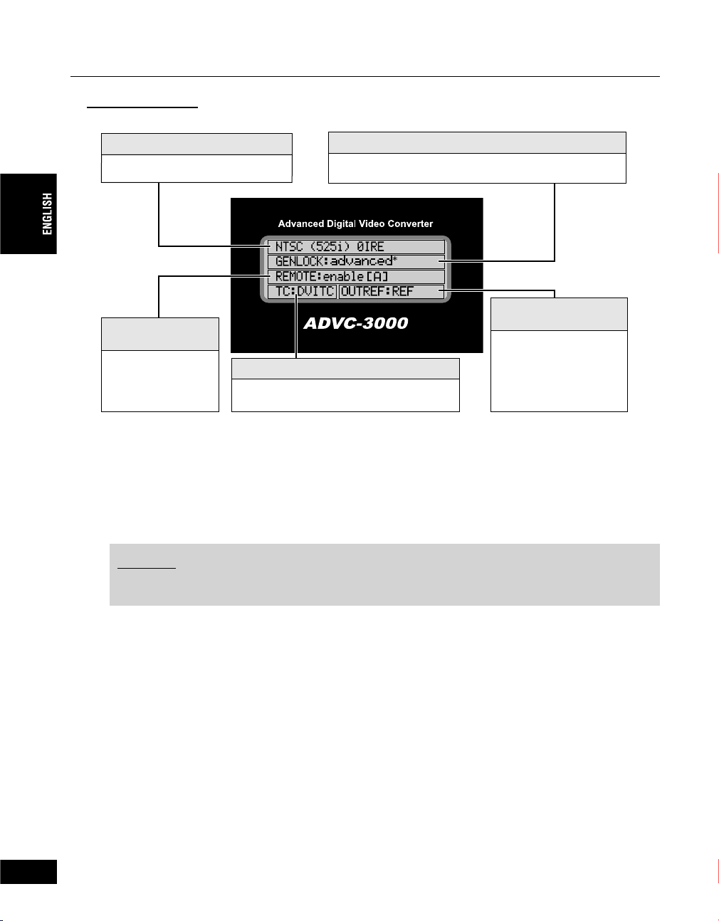
Main Screen 3
This screen shows the information on the current settings.
1. Video standard
Displays the current video standard.
3.
9-pin remote
enabled/disabled
Displays the current
setting of the 9-pin
remote.
4. Time code select
Displays time code selected in the
SDI/ANALOGDV mode.
2.External synchronization enabled/disabled
Displays the current setting of the external synchronization.
5.
Video output
reference
Displays the reference
signal with which the
SDI/ANALOG video
output is synchronized.
1.Video standard
NTSC ..........................ADVC3000 operates in NTSC mode.
PAL .............................ADVC3000 operates in PAL mode.
SECAM .......................ADVC3000 operates in SECAM mode.
2. External synchronization enabled/disabled
disable ........................External synchronization function is disabled.
enable .........................External synchronization function is enabled.
advanced ....................External synchronization function in the “perfect sync mode” is enabled.
24
26
NOTES
“advanced” setting is effective only when DV signal is output from the PC’s IEEE1394 board,
1394OHCI standard and “” is displayed.
3. 9-pin remote enabled/disabled
disable ........................9-pin remote control function is disabled.
enable[A] .....................Remote control connector A is selected.
enable[B] .....................Remote control connector B is selected.
4. Time code select
DVITC .........................
LTC .............................ADVC3000 is acquiring the time code from TC input connector.
auto .............................
5. Video output reference
REF .............................ADVC3000 is outputting the signal in synchronization with the REF signal
Vin ...............................ADVC3000 is outputting the signal in synchronization with the video
DVin ............................ADVC3000 is outputting the signal in synchronization with the DV-
INT ..............................ADVC3000 is outputting the internal SG signal (only in SG mode).
ADVC3000 is acquiring the time code from DVITC of the SDI input connector.
ADVC3000 tries to acquire the time code from both DVITC of the SDI input connector
and LTC and uses LTC if it is acquired and DVITC if LTC is not detected.
input from the REF IN connector.
signal selected by the VIDEO IN button.
decoded video signal (only in DVSDI/ANALOG mode).
Page 25
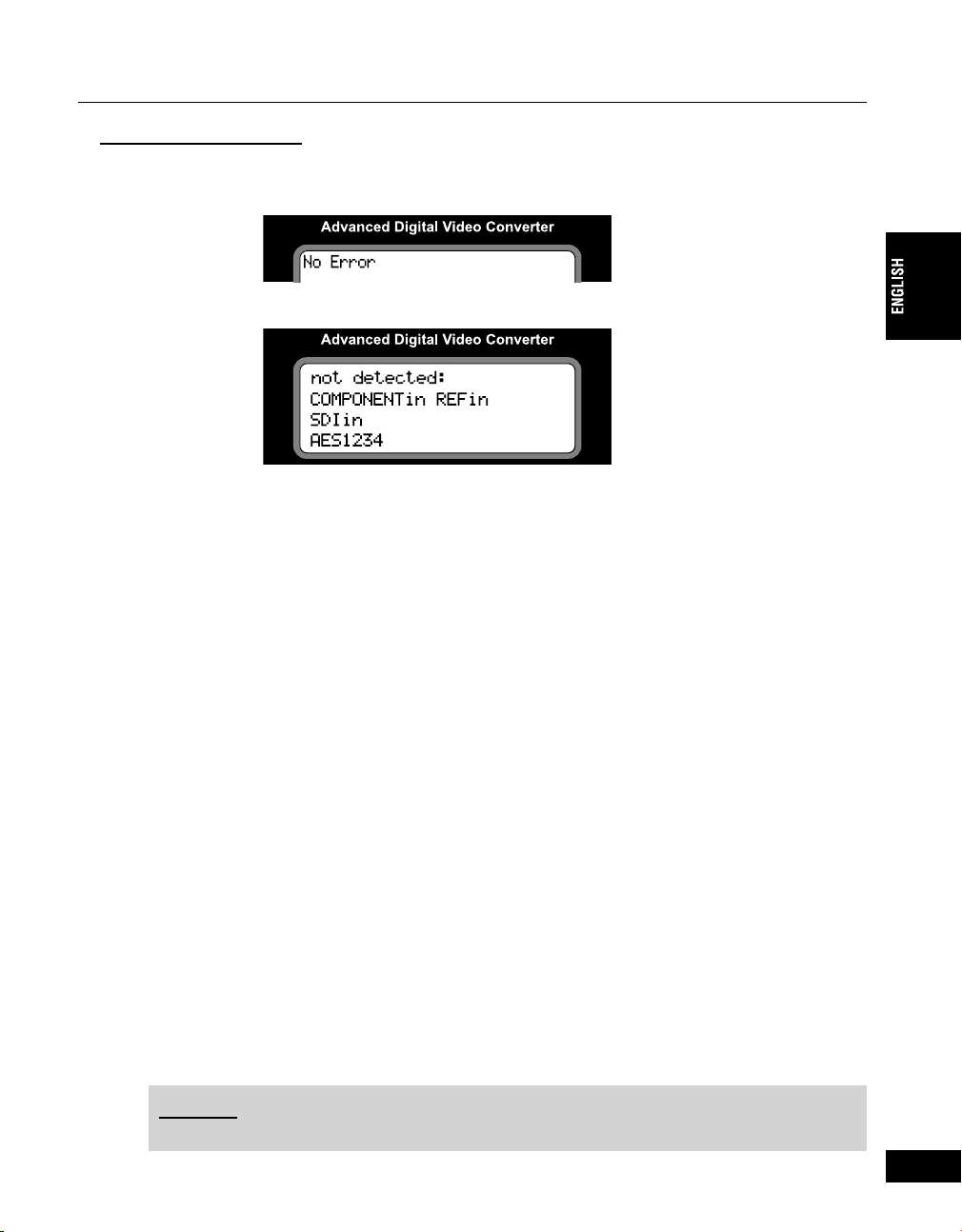
Error status screen
This screen shows error messages.
• When error is not detected
• When error is detected
COMPOSITEin/COMPONENTin/S VIDEOin/SDIin
• In SDI/ANALOGDV mode
Displayed when the video signal selected by the VIDEO IN button failed to be input. The LED does
not fl ash, however, when “104 DVout auto-mute” is set to “off”. “SDIin” is displayed when SDI audio
is selected by the AUDIO IN button but the SDI signal is not correctly recognized and LED does not
fl ash.
• In DVSDI/ANALOG mode
Displayed when the video signal selected by the VIDEO IN button failed to be input with “401 ext. sync”
set to “enable” or “advanced” (external sync is enabled) and with “404 ext. sync source” set to “input
video”.
REFin
• In SDI/ANALOGDV mode
Displayed when the REF signal cannot be detected in the REF IN connector (sync cannot be
locked) with “109 Vout ref. select” set to “REF”.
• In DVSDI/ANALOG mode
Displayed when
with “401 ext. sync” set to “enable” or “advanced” (external sync is enabled) and with “404
locked)
ext. sync source” set to “REF”.
the REF signal cannot be detected in the REF IN connector (sync cannot be
Chapter 2 - Basic Operations
AES12
AES/EBU audio input is selected for SDI/ANALOG DV mode, but signals for CH1 and CH2
can’t be detected.
AES 34
AES/EBU audio input is selected for SDI/ANALOG DV mode, but signals for CH3 and CH4
can’t be detected.
AES1234
AES/EBU audio input is selected for SDI/ANALOG DV mode, but signals for CH1, CH2, CH3
and CH4 can’t be detected.
NOTES
When “601 SG output” is set to ON, these messages will not be displayed.
25
27
Page 26
Chapter 2 - Basic Operations
2 Connecting devices
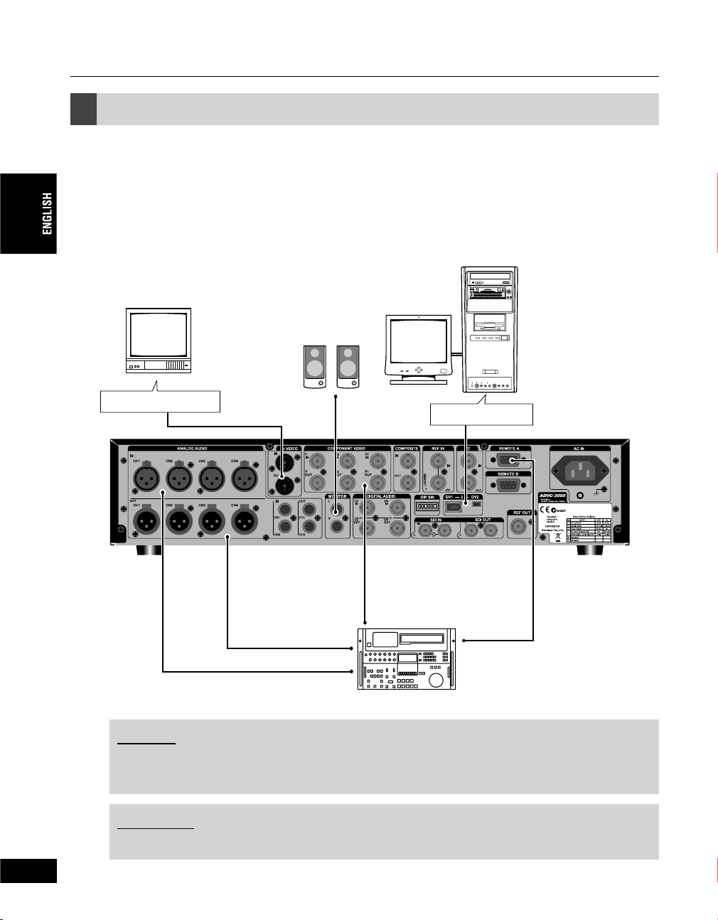
2-1. Connecting ADVC3000 unit
Connect the ADVC3000 unit to your system. The diagram below illustrates the typical connection of
the ADVC3000.
• Standard (Connection to a VCR with component connectors and a PC)
PC
Monitor
S-Video connector
Display
Speaker
DV connector
VCR with SDI
input/output
26
NOTES
DV editing software is required to playback or capture video fi les for use on a PC or to record the
fi le data onto tape. In addition, the PC should be equipped with an IEEE1394 connector.
CAUTION
When connecting a PC to the ADVC3000 unit, make sure that the PC’s power is turned off.
28
Page 27
Chapter 2 - Basic Operations
• System integrated (Connection to a VCR with SDI connectors and a PC)
PC
Speaker
Monitor
Video switcher with
SDI input/output
Sync signal
Display
VCR with SDI
input/output
Sync signal generator
* Analog connection (shown on page 26) and SDI connection (shown above) are possible at the same time. Input
source can be selected by the VIDEO IN button and the AUDIO IN button on the front panel.
NOTES
DV editing software is required to playback or capture video fi les for use on a PC or to record the
fi le data onto tape. In addition, the PC should be equipped with an IEEE1394 connector.
CAUTION
When connecting a PC to the ADVC3000 unit, make sure that the PC’s power is turned off.
27
29
Page 28
Chapter 2 - Basic Operations
'
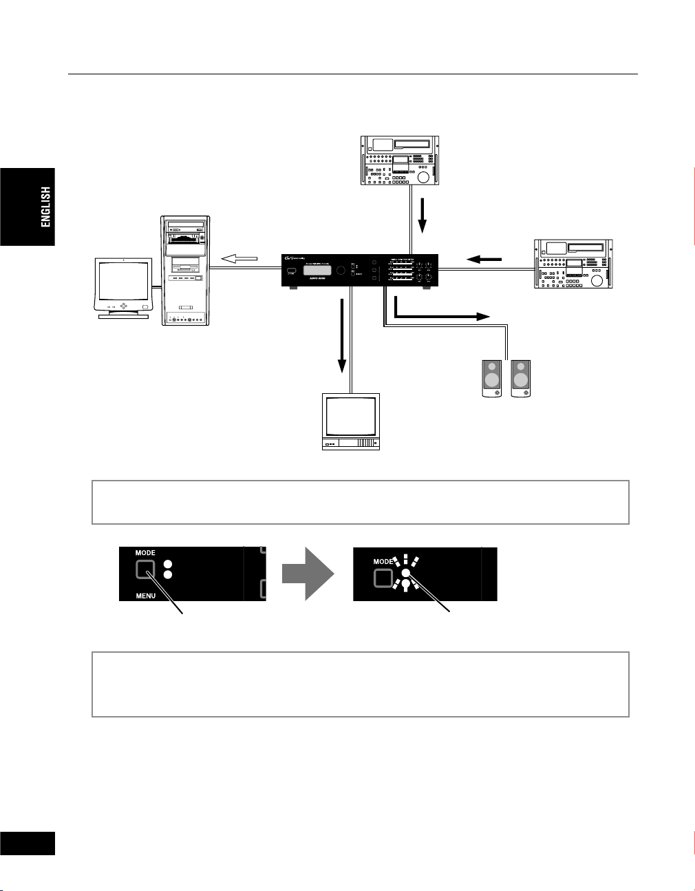
2-2. Importing VCR data to your PC
Import the material of the tape on VCR into a PC.
PC
(DV connector)
Display
Digital
ADVC3000
PRESET
SDI/ANALOG?DV
VIDEO IN
DV?SDI/ANALOG
AUDIO IN
Engineered by Canopus
VCR with
component
input/output
Analog
VCR with SDI
input/output
ANALOG AUDIO
INPUT LEVEL
SDI
COMPONENT
COMPOSITE
S VIDEO
SDI
AES/EBU
BALANCED
UNBALANCED
SDI
Analog
When entering the data
Analog
via DV editing software
Speaker
Monitor
Press the MODE button on the front panel of the ADVC3000 to switch the mode to [SDI/
1
ANALOG DV].
5&+#0#.1)ă&8
&8ă5&+#0#.1)
8+&
Press
Capture the data by using DV editing software.
2
* For the operational procedure of the DV editing software, refer to the instruction manual provided with your
DV editing software.
5&+#0#.1)ă&8
&8ă5&+#0#.1)
8+
Light
28
30
Page 29
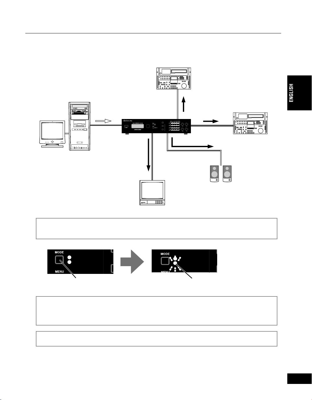
2-3. Recording PC-edited data onto a tape with VCR
&
'
Output the DV data from a PC and record it with a VCR.
VCR with
component
input/output
PC
Display
(DV connector)
Digital
ADVC3000
Engineered by Canopus
SDI/ANALOG?DV
DV?SDI/ANALOG
PRESET
SDI
VIDEO IN
COMPONENT
COMPOSITE
S VIDEO
SDI
AUDIO IN
AES/EBU
BALANCED
UNBALANCED
(DV connector)
Analog
ANALOG AUDIO
INPUT LEVEL
Analog
SDI
Chapter 2 - Basic Operations
VCR with SDI
input/output
When outputting the data
Analog
via DV editing software
Speaker
Monitor
Press the MODE button on the front panel of the ADVC3000 to switch the mode to the [DV
1
SDI/ANALOG].
5&+#0#.1)ă&8
&8ă5&+#0#.1)
8+&
Press
Use the DV editing software to output your data.
2
* For the operational procedure of the DV editing software, refer to the instruction manual provided with your
DV editing software.
5&+#0#.1)ă&8
&8ă5&+#0#.1)
8+
Light
Use the VCR to record the data on tape.
3
29
31
Page 30
Chapter 2 - Basic Operations
.
.
3 Menu setting operations
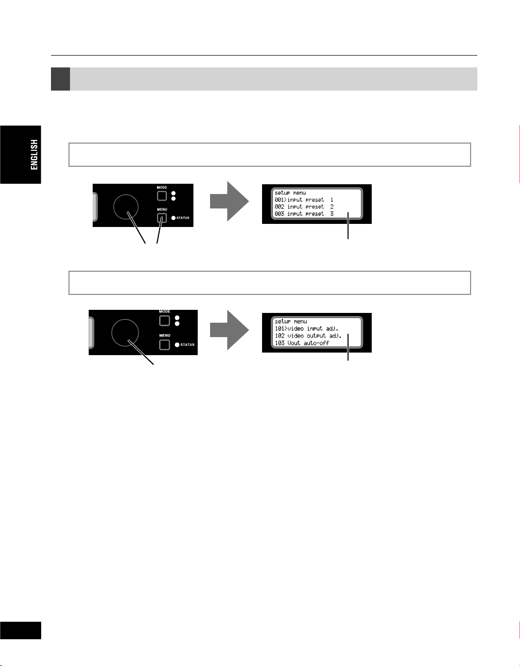
3-1. Menu screen operations
Press the Select dial or MENU button to go to the setting menu screen.
1
5&+#0#
&8ă5&+
Press
Turn the Select dial to choose the menu item to set.
2
5&+#0#
&8ă5&+
Tu r n
Setting menu is displayed on LCD
Choose the menu item
30
32
Page 31

Turn the Select dial clockwise to proceed to the setup menus.
Tu r n
Turn the Select dial counterclockwise to go back the setting menus.
Tu r n
Chapter 2 - Basic Operations
(Continued on the next page)
31
33
Page 32

Chapter 2 - Basic Operations
(Continued)
After selecting the menu item with the Select dial, turn the Select dial to change its setting.
3
If the menu item chosen has a sub-menu, press the Select dial to display the sub-menu.
Sub-menu
The item has been chosen in step 2.
Press the Select dial.
Turn the Select dial to choose the item.
Press the Select dial.
32
34
Turn the Select dial to choose the item.
Press the Select dial.
Turn the Select dial to choose the setting.
*Press the MENU button if you want to cancel the setting.
Press the Select dial.
The setting has been changed.
Press the MENU button to return to the main menu.
4
Page 33

Chapter 2 - Basic Operations
.
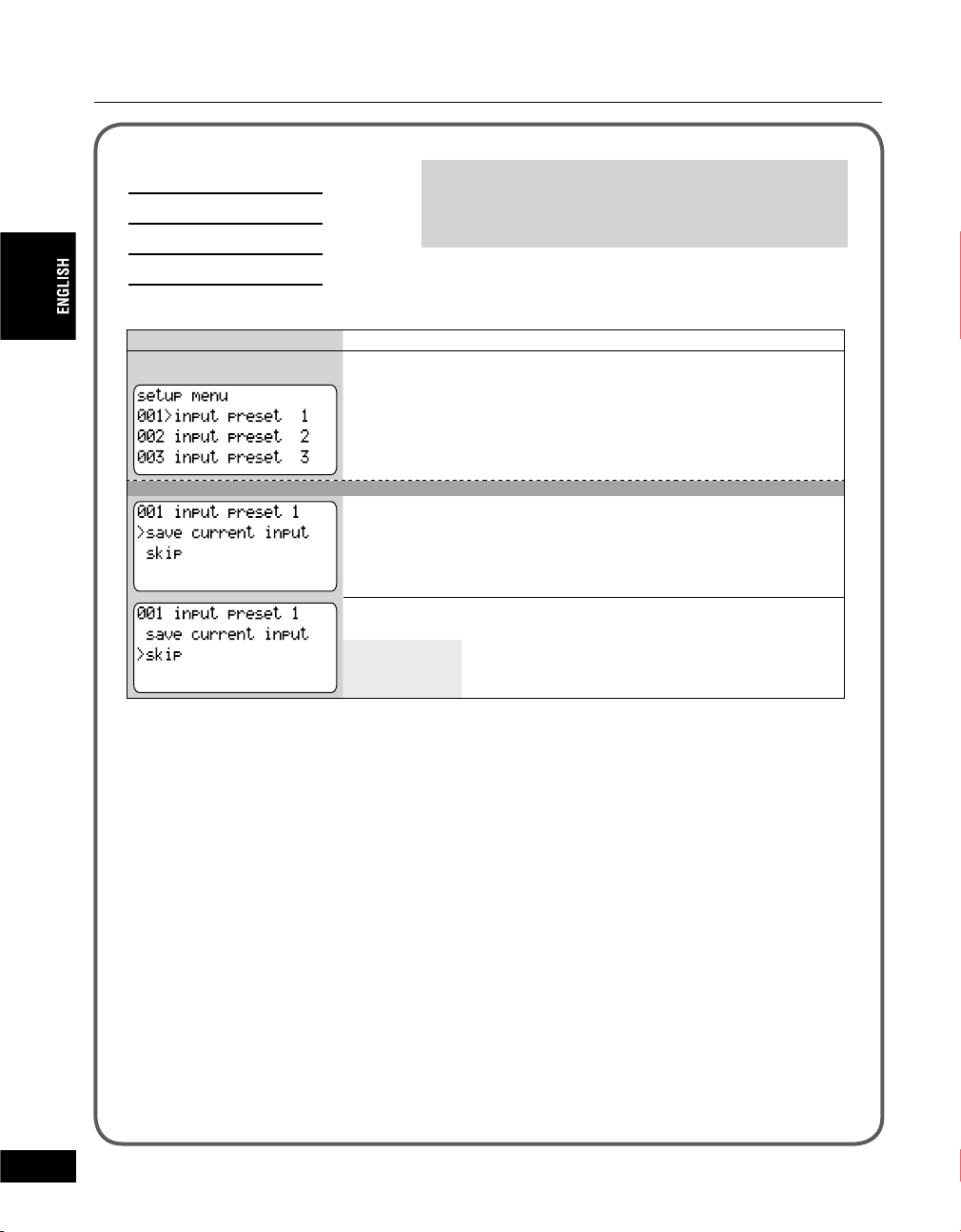
3-2. Presetting the video/audio input
4 combinations of video and audio input* can be stored in “001 input preset 1” to “004 input preset 4”
and can be recalled by one press of the button.
* In addition to video and audio input, remote A and B setting (501 9P remote) and DV audio format (201 DV audio
encode) setting can be stored in preset 1 to 4.
Storing the settings
Press the VIDEO IN button and AUDIO IN button to choose the desired input settings.
1
5&+8+&'1+0
%1/210'06
%1/215+6'
Press
Press the Select dial, or MENU button.
2
#7&+1+0
58+&'1
5&+
#'5'$7
$#.#0%'&
5&+#0#
&8ă5&+
Press
(Continued on the next page)
33
35
Page 34

Chapter 2 - Basic Operations
.
.
.
(Continued)
Turn the Select dial to choose the desired number (001 to 004) and press the Select dial.
3
5&+#0#
&8ă5&+
Turn and press
• You can make settings so that only some preset items will be recalled (unnecessary items can
be skipped).
1.Turn the Select dial to choose “skip” and press the Select dial.
2. Confi rm “on” is selected and press the Select dial to set the SKIP function.
Choose “off” when you want to cancel the SKIP function.
Confi rm “save current input” is selected and press the Select dial.
4
5&+#0#
&8ă5&+
34
36
Press
• When you want to go back to step 3, press the Select dial when “cancel” is chosen.
Turn the Select dial to display “save preset” and press the Select dial.
5
5&+#0#
&8ă5&+
Turn and press
The setting is stored and the screen at the step 3 is displayed.
• Repeat steps 2 to 5 to store another settings.
Page 35

Chapter 2 - Basic Operations
Recalling the settings
Press the PRESET button. Each time you press the button, settings 1 to 4 are
recalled in turn.
24'5'6
Press
5&+8+&'1+0
%1/210'06
%1/215+6'
37
35
Page 36

Chapter 2 - Basic Operations
3-3. Setting parameters
000 - 099 AV input settings
Video/audio input preset ----------------------------------------------
100 - 199 Video input/output settings
Video input adjustment settings -------------------------------------
Video output adjustment settings -----------------------------------
Video output auto-off settings ---------------------------------------
DV output auto-off setting ---------------------------------------------
DV output aspect ratio settings --------------------------------------
S-Video output aspect ratio setting ---------------------------------
Video standard settings -----------------------------------------------
DV out frame synchronizer setting ----------------------------------
Video output synchronizing signal settings -----------------------
Video out delay setting ------------------------------------------------
Audio out delay setting ------------------------------------------------
001 input preset 1 -------------- 38
002 input preset 2 -------------- 38
003 input preset 3 -------------- 38
004 input preset 4 -------------- 38
101 video input adj. ----------- 39
102 video output adj ---------- 43
103 Vout auto-off --------------- 44
104 DVout auto-mute --------- 45
105 DV aspect info ------------- 46
106 Sout aspect info ----------- 47
107 video standard ------------- 48
108 DVout frame sync --------- 48
109 Vout ref. select ------------- 49
110 Vout ref. conf. -------------- 49
111 Vout audio delay ---------- 49
36
38
200 - 299 Audio input/output settings
DV audio encode setting ----------------------------------------------
Balanced audio headroom (Reference level) --------------------
Balanced audio input/output level ----------------------------------
Analog monitor audio mixing output -------------------------------
Balanced audio (XLR) input termination --------------------------
300 - 399 Time code settings
DV encoding time code settings-------------------------------------
DVITC settings -----------------------------------------------------------
201 DV audio encode --------- 50
202 audio headroom ---------- 50
203 audio level ----------------- 51
204 analog audio mon -------- 51
205 600 ohm term. ------------ 52
301 TC source ------------------- 52
302 VITC insert line ------------ 53
Page 37

400 - 499 External synchronization settings
External synchronization ----------------------------------------------
External synchronization confi guration ----------------------------
Audio out delay setting ------------------------------------------------
External synchronization source settings -------------------------
500 - 599 9-pin remote control settings
9-pin remote control setting ------------------------------------------
600 - 699 Signal generator output settings
Color bar output ---------------------------------------------------------
SG audio level -----------------------------------------------------------
700 - 799 Other detailed settings
IEEE1394 clock adjustment ------------------------------------------
Local switch disable ----------------------------------------------------
Resample fi lter setting -------------------------------------------------
AV/C transaction setting -----------------------------------------------
Maximum data rate setting -------------------------------------------
LCD backlight illuminating period settings ------------------------
LED brightness settings -----------------------------------------------
Chapter 2 - Basic Operations
401 ext. sync -------------------- 54
402 ext. sync conf. ------------- 54
403 audio out delay ------------ 55
404 ext. sync source ----------- 55
501 9P remote------------------- 55
601 SG output ------------------- 56
602 SG audio level ------------- 56
701 1394 clock adj. ------------ 57
702 local disable --------------- 57
704 resample fi lter ------------- 58
705 AV/C transaction ---------- 58
706 data rate cap. -------------- 59
707 LCD backlight ------------- 60
708 LED dimmer---------------- 60
900 - 999 System settings
Save settings -------------------------------------------------------------
Restore settings (Default settings) ---------------------------------
System version ----------------------------------------------------------
901 save settings ---------------- 61
902 restore settings ------------- 61
903 system version ------------- 62
37
39
Page 38
Chapter 2 - Basic Operations
001 input preset 1
002 input preset 2
003 input preset 3
004 input preset 4
Video/audio input preset
LCD display
Example: Preset 1
Stores 4 combinations of video and audio input. Each
time you press the PRESET button, preset 1 to 4 is
recalled in turn. (Refer to page 33 for details.)
Selects the preset to be stored.
Sub-menu
Stores the current preset.
Selects whether the preset is recalled or skipped when the PRESET
button is pressed.
off To be recalled when the PRESET button is pressed.
on
To be skipped when the PRESET button is pressed.
38
40
Page 39

Chapter 2 - Basic Operations
101 video input adj.
Adjusts the video quality of the input video.
Video input adjustment settings
* According to the settings of the video standard or video input, some menu items may not be
available and do not appear in the display.
1. Select the video input and press the Select dial.
2. Turn the Select dial to select the item to be adjusted from the sub-menu and press the Select
dial.
Example:
* When setting the sub-menu, you cannot change settings with PRESET button, VIDEO IN
button and AUDIO IN button.
Sub-menu items
brightness Adjusts brightness of image. The smaller the value is, the darker the image is; the
larger, the brighter.
Set specifi ed numerical value between 0 and 1023. (Factory default: 512)
contrast Adjusts contrast of image. The smaller the value is, the weaker the contrast is; the
larger, the stronger.
Set specifi ed numerical value between 0 and 255. (Factory default: 128)
hue Adjusts hue of image. Taking yellow as an example, the smaller the value is, the
closer to red; the larger, the closer to green.
Set specifi ed numerical value between 0 and 255. (Factory default: 128)
(Continued on the next page)
39
41
Page 40

Chapter 2 - Basic Operations
(Continued)
saturation Adjusts color strength. The smaller the value is, the lighter the color is; the larger,
the darker. You can reproduce complete gray-scale with minimum value 0 (zero).
Set specifi ed numerical value between 0 and 255.
(Factory default: For composite/S video)
NTSC 0 IRE: 128, 7.5 IRE: 138, PAL:128, SECAM:128
(Factory default: For component)
NTSC Betacam 0 IRE:148, 7.5IRE:160, SMPTE:148, PAL:213, SECAM:213
sharpness Adjusts sharpness of image outline. The smaller the value is, the more blur image
outline is; the larger, the sharper.
Set specifi ed numerical value between 0 and 255. (Factory default: 128)
component level Specifi es the component level (NTSC/component only)
Betacam Sets Betacam (Factory default)
SMPTE Sets SMPTE.
3D visual
processing
2D Iuma NR Eliminates the noise on the luminance component by non-linear noise extract
Sets the effects for 3D noise reduction and 3D video processing. (NTSC only)
(Available only to composite or S-video)
none Disables the 3D noise reduction. (Factory default)
3D Y/C Enables 3D Y/C. (composite only)
3D NR (low) Enables low 3D noise reduction fi lter.
3D NR
(middle)
3D NR (high) Enables high 3D noise reduction fi lter.
fi lter.
none Disables the 2D luminance noise extract. (Factory default)
low Enables low 2D noise extract fi lter.
middle Enables medium 2D noise extract fi lter.
high Enables high 2D noise extract fi lter.
Enables medium 3D noise reduction fi lter.
40
(Continued on the next page)
42
Page 41

Chapter 2 - Basic Operations
(Continued)
2D chroma NR Eliminates the noise on the color component by non-linear noise extract fi lter.
none Disables the 2D chrominance noise extract. (Factory default)
low Enables low 2D noise extract fi lter.
middle Enables medium 2D noise extract fi lter.
high Enables high 2D noise extract fi lter.
black gain Strengthens the gain in low luminance area toward luminance signal. As the setting
becomes stronger, black gain becomes more emphasized.
When set to [none], the “B adaptation level”, “black threshold” settings will be
invalid.
none Disables the black gain. (Factory default)
low Enables low black gain fi lter.
middle Enables medium black gain fi lter.
high Enables high black gain fi lter.
B adaptation level
black threshold Specifi es the luminance level to enhance black element. The higher the value, the
white gain Weakens the gain in high luminance areas toward luminance signal. This option
Sets the adjustment volume for black expansion. As the adjustment volume is
larger, the black gain becomes more emphasized.
level 1 (Factory default)
level 2 to 4
brighter the luminance level will be.
Set specifi ed numerical value between 0 and 255. (Factory default: 0)
improves reproduction of gradation in damaged area that are seen as white due to
high luminance.
When set to [none], the “W adaptation level”, “white threshold” settings will be
invalid.
none Disables the white gain. (Factory default)
low Enables low white gain fi lter.
middle Enables medium white gain fi lter.
high Enables high white gain fi lter.
(Continued on the next page)
41
43
Page 42

Chapter 2 - Basic Operations
(Continued)
W adaptation
level
white threshold Sets the level of luminance (brightness) to which white gain will be lowered. Larger
H outline
enhance
V outline enhance Sets the outline adjustment for vertical direction (edge of horizontal line).
Sets the adjustment volume for white gain limit. As the limit volume is larger, white
gain will be adjusted to lower.
level 1 (Factory default)
level 2 to 4
values will result in darker level settings.
Set specifi ed numerical value between 0 and 255. (Factory default: 255)
Sets the outline adjustment for horizontal direction (edge of vertical line).
none Disables horizontal outline enhance. (Factory default)
low Enables low horizontal outline enhance.
middle Enables medium horizontal outline enhance.
high Enables high horizontal outline enhance.
none Disables vertical outline enhance. (Factory default)
low Enables low vertical outline enhance.
middle Enables medium vertical outline enhance.
high Enables high vertical outline enhance.
42
3. Turn the Select dial to choose the setting and press the Select dial.
Example:
44
Page 43

Chapter 2 - Basic Operations
102 video output adj
Video output adjustment settings
LCD display
Specifi es the component level (NTSC only).
Betacam Specifi es the component level to Betacam.
SMPTE
Adjusts the composite/S gain.
Set specifi ed numerical value between -32 and 32. (Factory default: 0)
Adjusts the component gain.
Set specifi ed numerical value between -32 and 32. (Factory default: 0)
Adjusts settings on output video.
Press the Select dial to display the sub-menu.
In the sub-menu, turn the Select dial to adjust the level or setting.
Sub-menu
(Factory default)
Specifi es the component level to SMPTE.
45
43
Page 44

Chapter 2 - Basic Operations
103 Vout auto-off
Video output auto-off settings
LCD display
Specifi es the output connector that automatically
stops the video output in SDI/ANALOGDV mode.
When the reference signal is not used, set this option
to [auto-off] to prevent a looped connection with a
connected device.
Press the Select dial to display the sub-menu.
In the sub-menu, turn the Select dial to set the item.
Sub-menu
Specifi es the SDI output setting.
output Does not stop outputting video signal.
(Factory default)
auto-off
Specifi es the component output setting.
output Does not stop outputting video signal.
auto-off
Specifi es the composite output setting.
output Does not stop outputting video signal.
auto-off
Stops outputting video signal.
(Factory default)
Stops outputting video signal.
(Factory default)
Stops outputting video signal.
44
46
Specifi es the S-video output setting.
output Does not stop outputting video signal.
(Factory default)
auto-off
Stops outputting video signal.
Page 45

Chapter 2 - Basic Operations
104 DVout auto-mute
DV output auto-off setting
LCD display
Selects the conditions where ADVC3000
automatically stops the DV stream in SDI/
ANALOGDV mode.
Does not stop DV stream.
Stops DV stream automatically when video is not input. (Factory default)
47
45
Page 46

Chapter 2 - Basic Operations
105 DV aspect info
DV output aspect ratio settings
LCD display
For NTSC
For PAL/SECAM
Specifi es the aspect ratio for the DV stream that
ADVC3000 outputs in SDI/ANALOGDV mode.
Sets the DV stream in 4:3 aspect ratio. (Factory default)
Sets the DV stream in16:9 aspect ratio (letter box).
Sets the DV stream in16:9 aspect ratio (squeeze).
Sets the DV stream in 4:3 aspect ratio. (Factory default)
46
Sets the DV stream in16:9 aspect ratio (letter box).
Sets the DV stream in16:9 aspect ratio (anamorphic).
* This is effective only when the DV device to which the signals are output is compatible with the aspect signal of
DV standard.
48
Page 47

Chapter 2 - Basic Operations
106 Sout aspect info
Specifi es the aspect ratio for the S-Video that
ADVC3000 outputs.
S-Video output aspect ratio setting
LCD display
Sets the S-Video in 4:3 aspect ratio. (Factory default)
Sets the S-Video in16:9 aspect ratio (letter box).
Sets the S-Video in16:9 aspect ratio.
* This is effective only when the video device to which the signals are output is compatible with the aspect signal
of S Video standard.
49
47
Page 48

Chapter 2 - Basic Operations
107 video standard
Video standard settings
LCD display
Select the video standard.
NTSC(525)/
0IRE
NTSC(525)/
7.5IRE
PAL(625) Sets to PAL.
SECAM(625) Sets to SECAM.
set by DIP
switch
108 DVout frame sync
DV out frame synchronizer setting
LCD display
Specifi es the video standard. Once you have changed
the video standard settings (or the setup level), you
are prompted to turn the power off to make the new
setting take effect.
Press the Select dial to display the sub-menu.
In the sub-menu, turn the Select dial to display the sub-menu in
turn.
Sub-menu
Sets to NTSC with the setup level of 0 IRE.
Sets to NTSC with the setup level of 7.5 IRE.
Adopts the setting by the DIP switch on the rear panel.
(Factory default)
Enables/Disables the frame synchronizer on the output
DV stream in SDI/ANALOGDV mode.
48
Disables the frame synchronizer. (Factory default)
Enables the frame synchronizer.
* Regardless of this setting, the synchronizer takes effect on the output analog video.
* The sync signal of the frame synchronizer is set in “109 Vout ref. select”.
* This option is invalid if “501 9P remote” is set to remote A or remote B.
50
Page 49

Chapter 2 - Basic Operations
109 Vout ref. select
Selects the source to be used as sync signal in SDI/
ANALOGDV mode.
Video output synchronizing signal settings
LCD display
Synchronizes with the chosen video signal.
(Factory default)
Synchronizes with the sync signal to be input through REF IN connector.
110 Vout ref. conf.
Sets the amount (in unit of 37 nanoseconds) to
increase/decrease the ADVC3000 video output delay
(system phase) relative to the synchronization source
in SDI/ANALOGDV mode.
Video out delay setting
LCD display
Set specifi ed numerical value between -1024 and 1023.
(Factory default: 0)
111 Vout audio delay
Audio out delay setting
LCD display
Sets the amount (in unit of milliseconds) to increase/
decrease the ADVC3000 audio output delay relative to
the video output, when the external sync is enabled in
SDI/ANALOGDV mode.
* When “108 DVout frame sync” is set to disable, the DV output
data is not delayed.
Set specifi ed numerical value between -100 and 100 msec.
(Factory default: 0)
49
51
Page 50

Chapter 2 - Basic Operations
201 DV audio encode
DV audio encode setting
LCD display
202 audio headroom
Balanced audio headroom
(Reference level)
LCD display
Specifi es the DV audio format and channel in SDI/
ANALOGDV mode.
Encodes audio input CH1 and CH2 in the audio format of 48kHz/16bit.
(Factory default)
Encodes audio input CH1, CH2, CH3, and CH4 in the audio format of
32kHz/12bit.
Encodes audio input CH3 and CH4 in the audio format of 48kHz/16bit.
Specifi es the input/output headroom of the Balanced
audio (XLR).
Press the Select dial to display the sub-menu.
In the sub-menu, turn the Select dial to move the cursor. When
the Select dial is pressed, headroom of the highlighted channel
is changed.
50
52
Sub-menu
Specifi es the input headroom.
16 dB Sets to 16 dB.
18 dB Sets to 18 dB. (Factory default for PAL/SECAM)
20 dB Sets to 20 dB. (Factory default for NTSC)
Specifi es the output headroom.
16 dB Sets to 16 dB.
18 dB Sets to 18 dB. (Factory default for PAL/SECAM)
20 dB
Sets to 20 dB. (Factory default for NTSC)
Page 51

Chapter 2 - Basic Operations
203 audio level
Balanced audio input/output level
LCD display
Specifi es the input level of the balanced audio.
+4 dBm Sets to +4 dBm. (Factory default)
0 dBm
Specifi es the output level of the balanced audio.
+4 dBm Sets to +4 dBm. (Factory default)
0 dBm
204 analog audio mon
Analog monitor audio mixing output
LCD display
Specifi es the input/output level of the Balanced audio
(XLR).
Press the Select dial to display the sub-menu.
In the sub-menu, turn the Select dial to move the cursor, and press
the Select dial again to change the input/output level of the channel
that you select.
sub-menu
Sets to 0 dBm.
Sets to 0 dBm.
Sets the mix output to the analog monitor audio output
connectors.
Turn the Select dial to select the channel and press the Select dial
to turn on or off the channel.
Selected channels will be mixed and output for each L and R of
the analog monitor audio output connectors.
51
53
Page 52

Chapter 2 - Basic Operations
205 600 ohm term.
Balanced audio (XLR) input termination
LCD display
Press the Select dial to move the cursor, and press the Select dial
to change ON/OFF alternately.
ON
OFF High impedance
301 TC source
DV encoding time code settings
LCD display
Acquires time code from DVITC of the SDI input connector.
*Incompatible with VITC from the analog video input connector.
Acquires time code from LTC of the TC input connector.
Sets the termination at the balanced audio (XLR) input
connector.
600 termination
Reads the time code from the deck in SDI/
ANALOGDV mode.
52
Acquires time code from DVITC in SDI input and LTC. Adopts LTC if LTC
is acquired, adopts DVITC only if not.
(Factory default)
54
Page 53

Chapter 2 - Basic Operations
302 VITC insert line
DVITC settings
LCD display
Selects the line at which DVITC is inserted in SDI
output or the line at which DVITC is read from SDI
input.
Press the Select dial to display the sub-menu. In the sub-menu,
turn the Select dial to select the line.
Sub-menu
Sets the line (line 1) in which to insert DVITC in SDI output.
line ××
off
Sets the line (line 2) in which to insert DVITC in SDI output.
line ××
off
Sets the line in which to read DVITC from SDI input in SDI/ANALOG
DV mode.
line ××
auto detect
NTSC: 10 to 20 (Factory default: 16)
PAL: 6 to 22 (Factory default: 19)
Will not be inserted.
NTSC: 10 to 20 (Factory default: 18)
PAL: 6 to 22 (Factory default: 21)
Will not be inserted.
NTSC: 10 to 20
PAL: 6 to 22
Detects automatically. (Factory default)
55
53
Page 54

Chapter 2 - Basic Operations
401 ext. sync
External synchronization
LCD display
Disables the external sync operation.
(Factory default)
Enables the external sync operation.
Enables the external sync operation as “perfect sync mode”.
* The “advanced” setting is only available when DV signal is output from an IEEE1394 connector compliant with PC
OHCI specifi cations. For supported PC operating systems, please refer to our website.
* When the ADVC3000 is connected to Canopus ADVC units through DV connectors, do not set to the “perfect sync
mode”.
Enables/Disables the external sync operation in DV
SDI/ANALOG mode.
54
56
402 ext. sync conf.
External synchronization
confi guration
LCD display
Sets the amount (in unit of 37 nanoseconds) to
increase/decrease the ADVC3000 video output delay
(system phase) relative to the external sync input in
DV
SDI/ANALOGmode.
Set specifi ed numerical value between -1024 and 1023.
(Factory default: 0)
Page 55

Chapter 2 - Basic Operations
403 audio out delay
Audio out delay setting
LCD display
404 ext. sync source
External synchronization
source settings
LCD display
Sets the amount (in unit of milliseconds) to increase/
decrease the ADVC3000 audio output delay relative to
the video output, when the external sync is enabled in
DV
SDI/ANALOG mode.
Set specifi ed numerical value between -100 and 100 msec.
(Factory default: 0 msec)
Sets the source used as the sync signal when
performing external synchronization in DV
SDI/
ANALOG mode.
Synchronizes to sync signal contained in video signal input from the
input connector selected by the VIDEO IN button.
Synchronizes to signal input into REF IN connector.
(Factory default)
501 9P remote
9-pin remote control setting
LCD display
Enables/Disables the deck control from the 9-pin
remote controller.
Disables the deck control from the remote connector.
Enables the deck control from the remote A connector.
(Continued on the next page)
55
57
Page 56

Chapter 2 - Basic Operations
(Continued)
Enables the deck control from the remote B connector.
601 SG output
Selects the color bar output mode.
Color bar output
LCD display
Does not output color bar.
(Factory default)
Outputs color bar.
* External synchronization function cannot be used.
* Free-run time-code is output.
602 SG audio level
SG audio level
LCD display
Selects the testing audio signal of 1kHz in color bar
output mode.
56
Sets to -18 dB FS. (Factory default for PAL/SECAM)
Sets to -20 dB FS. (Factory default for NTSC)
58
Page 57

701 1394 clock adj.
IEEE1394 clock adjustment
LCD display
Chapter 2 - Basic Operations
Sets the IEEE1394 system clock.
In most cases, factory default settings (127) should be used.
(Factory default: 127)
702 local disable
Local switch disable
LCD display
Enables/Disables the MODE button, VIDEO IN button,
AUDIO IN button and PRESET button.
Permits operation by the MODE button, VIDEO IN button, AUDIO IN
button and PRESET button.
(Factory default)
Prohibits operation by the MODE button, VIDEO IN button, AUDIO IN
button and PRESET button.
Prohibits operation by the MODE button, VIDEO IN button, AUDIO
IN button and PRESET button, only when the deck control by 9-pin
remote connector is enabled.
Permits operation by the MODE button, VIDEO IN button, AUDIO IN
button and PRESET button, with the switching by AV/C command
prohibited.
59
57
Page 58

Chapter 2 - Basic Operations
704 resample fi lter
Resample fi lter setting
LCD display
705 AV/C transaction
AV/C transaction setting
LCD display
Selects the type of horizontal resampling fi lter for Cb/
Cr signal.
(NTSC only)
Sets normal modulus.
(Factory default)
Sets modulus that emphasizes anti-alias.
Sets modulus that emphasizes frequency characteristic.
Selects the type of AV/C transaction at the time AV/C
command is received.
58
Executes AV/C immediate transaction.
(Factory default)
Sends INTERIM response, and then executes AV/C immediate
transaction.
60
Page 59

Chapter 2 - Basic Operations
706 data rate cap.
Maximum data rate setting
LCD display
Selects the maximum communication speed of the “dr
cap” fi eld of “iMPR/oMPR” at the time of booting and
setting change.
Once you have changed this setting, you are prompted
to turn the power off to make the new setting take
effect.
Sets to S100.
(Factory default)
Sets to S200.
Sets to S400.
61
59
Page 60

Chapter 2 - Basic Operations
707 LCD backlight
LCD backlight illuminating period settings
LCD display
Press the Select dial to display the sub-menu.
In the sub-menu, turn the Select dial to select the lighting period.
Lights for 5 seconds after operating the front panel.
Lights for 10 seconds after operating the front panel.
The backlight always lights.
(Factory default)
708 LED dimmer
LED brightness settings
LCD display
Sets the backlight lighting period of the front panel LCD.
sub-menu
Sets the brightness of the front panel LED.
60
Turn the Select dial to display the sub-menu.
In the sub-menu, turn the Select dial to select the brightness.
sub-menu
Sets to 50% brightness.
Sets to 100% brightness.
(Factory default)
* Power LED cannot be darkened.
62
Page 61

901 save settings
Save settings
Chapter 2 - Basic Operations
Saves the current setting to the user 1 to 3 settings.
1. Turn the Select dial to select user 1 to 3, and press the Select
dial.
user1: save the current setting as user 1
user2: save the current setting as user 2
user3: save the current setting as user 3
2. Turn the Select dial and display “save settings” (fl ashing) to
save the current settings, and press the Select dial.
When you cancel the setting, display “cancel” (fl ashing) and
press the Select dial.
(returns to the step 1 display)
902 restore settings
Restore settings (Default settings)
Restores the current settings to the user setting, or to
the factory default.
Once you have changed this setting, you may be
prompted to turn the power off to make the new setting
take effect.
1. Turn the Select dial to select user 1 to 3 or “factory default”, and
press the Select dial.
user1: return the setting to user 1 setting
user2: return the setting to user 2 setting
user3: return the setting to user 3 setting
factory default: return the setting to the factory default
2. Turn the Select dial and display “restore settings” (fl ashing) to
change the settings, and press the Select dial.
When you cancel the setting, display “cancel” (fl ashing) and
press the Select dial.
(returns to the step 1 display)
63
61
Page 62

Chapter 2 - Basic Operations
903 system version
System version
LCD display
This item contains sub-menus displaying fi rmware
version numbers.
Press the Select dial to display the sub-menu.
In the sub-menu, turn the Select dial to choose the sub-menu
item.
sub-menu
Displays uCOM version.
Displays FPGA version.
Displays CPLD 1 version.
62
Displays CPLD 2 version.
Displays unit ID.
* The version numbers displayed above are examples and the actual screen may differ from the above screens.
64
Page 63

3000
Chapter 3
Appendix
This chapter provides supplementary information
regarding the ADVC3000 operations.
- Specifi cations
65
63
Page 64

Chapter 3 - Appendix
1 Specifi cations
Video signal
DV input/output
Video input
Video output
Audio input
Audio output
TC input/output
Composite
S Video
Component
SD-SDI/DV
* 59.94i 50i conversion is not possible.
SD-SDI BNC x 2 (SD-SDI IN + ACTIVE THROUGH, SMPTE 259M-C)
Component BNC (Component x 1, Y/Pb/Pr)
Y/C S teminal x 1
Composite BNC x 1 (Composite)
SD-SDI BNC x 2 (SMPTE 259M-C)
Component BNC (Component x 1, Y/Pb/Pr)
Y/C S teminal x 1
Composite BNC x 1 (Composite)
SD-SDI Embedded audio (SMPTE 272M-A)
AES/EBU
Balanced
Unbalanced Pin jack (stereo 1 line, CH1 and CH2)
DV
SD-SDI Embedded audio (SMPTE 272M-A)
AES/EBU BNC x 2 (CH1 to CH4)
Balanced XLR-3-32 x 4 (CH1 to CH4)
Unbalanced Pin jack (stereo 1 line, CH1 and CH2)
DV
Monitor output Pin jack (stereo 1 line, mapping CH1 to CH4 on L/R is possible)
LTC input BNC x 1
LTC output BNC x 1
DVITC input
DVITC output
NTSC (525/59.94i), PAL (625/50i)
* SECAM is available only for input. In that case, PAL signal is
output.
525/59.94i, 625/50i
IEEE1394 4 pin x 1, IEEE1394 6 pin x 1(Without bus power
supply)
* Incompatible with DV stream of DVCPRO standard.
Option/update is necessary to make DV standard stream output
to DVCPRO VCR.
BNC x 2 (CH1 to CH4)
32/44.1/48kHz, 16/20/24bit, Unlocked/Locked
Can be converted anytime to 48kHz. Locked by built-in SRC
XLR-3-31 x 4 (CH1 to CH4)
*600 termination or high impedance is selectable.
32/44.1/48kHz (Unlocked/Locked) 16bit, 2ch
32kHz (Unlocked/Locked) 12bit, 4ch
48kHz/Locked/16bit/2ch
32kHz/Locked/12bit/4ch
Separated from SD-SDI input
*Incompatible with VITC from analog video input
Repeatedly overlaps with SD-SDI output
* Line select function is available.
* Also overlaps with analog video.
64
66
Page 65

Chapter 3 - Appendix
Reference input B.B input
Reference output B.B output
REMOTE output
Others Front panel
Power source AC 100-240V, 50/60Hz
Current consumption 0.44A (100V), 0.21A (240V)
Operating temperature 10–35°C
General specifi cations
Outside dimension
Weight Approx 4.6kg
BNC x 2 (INPUT and LOOP THROUGH, automatic 75
termination)
BNC x 1
* Does not synchronize with video output.
RS-422A (D-sub 9 pin) x 2
Command converter for AV/C RS422A
Input level adjusting volume (CH1 to CH4)
Audio level meter
Preset button
Video input select button
Video input indicator
Audio input select button
Audio input indicator
Select dial, Menu button
Mode LED
Status LED
Other LCDs
430(W) x 88(H) x 270(D) mm
(excluding projecting parts and rubber feet)
19" half rack-mounting
67
65
Page 66

Hinweise und Garantie
Copyright-Bestimmungen
Jede Verletzung der in den Copyright-Gesetzen festgeschriebenen Rechte des Inhabers des Copyrights
ist ungesetzlich. Ausgenommen davon sind zulässige Verwendungen (hauptsächlich private, nichtkommerzielle Verwendungen). In bestimmten Fällen ist das Kopieren ausnahmslos verboten. Canopus ist
in keinem Fall für direkte oder indirekte Schäden jeglicher Art haftbar, die sich aus der Verwendung der
aufgezeichneten Materialien ergeben.
Garantie
Wenn Sie Ihr Canopus-Erzeugnis registrieren, gilt für Ihren ADVC3000 und Zubehör eine eingeschränkte
Garantie. Diese Garantie gilt für einen Zeitraum von einem Jahr (oder zwei Jahren in Ländern der
Europäischen Union) ab dem Datum des Kaufs von Canopus oder von einem autorisierten CanopusHändler. Diese Garantie gilt nur für den Erstkäufer des Canopus-Erzeugnisses und ist nicht übertragbar.
Canopus Co., Ltd. garantiert für diesen Zeitraum die fehlerfreie Funktion des Erzeugnisses. Sollte unser
Produkt nicht fehlerfrei funktionieren, wird Canopus nach eigener Wahl dieses ohne weiteren Kosten
für Sie reparieren oder ersetzen, vorausgesetzt, dass das Erzeugnis keiner Zweckentfremdung und
keinem Missbrauch ausgesetzt wurde und dass keine von Canopus nicht autorisierten Abänderungen,
Veränderungen und/oder Reparaturen am Erzeugnis vorgenommen wurden. Für die Überprüfung Ihrer
Garantieansprüche ist ein Kaufnachweis erforderlich.
Canopus ist nicht für entgangene Gewinne, verlorene Einsparungen oder andere Folgeschäden oder sich
daraus ergebende Schäden verantwortlich, die sich aus der Verwendung oder der Nichtverwendbarkeit
dieses Erzeugnisses ergeben. Dies gilt auch für auch Sachschäden und, bis zum durch geltendes Recht
abgedeckten Umfang, Personenschäden. Diese Garantie ersetzt alle anderen Garantieerklärungen der
Handelbarkeit und der Verwendbarkeit für einen bestimmten Zweck.
Vorsicht
Bitte beachten Sie bei der Verwendung dieses Erzeugnisses die folgenden Vorsichtsmaßnahmen. Falls
Sie Fragen zur Art und Weise der Verwendung und zu den folgenden Beschreibungen oder sonstige
Fragen zum Erzeugnis haben, wenden Sie sich bitte an den Technischen Kundendienst von Canopus.
2
68
Page 67

Hinweise und Garantie
GEFAHR
Unter den folgenden Bedingungen besteht die Möglichkeit schwerer bis tödlicher Verletzungen.
Gesundheitliche Vorsichtsmaßnahmen
In seltenen Fällen kann blinkendes Licht oder eine Reizung durch das helle Licht eines Computerbildschir ms
oder eines Fernsehgeräts möglicherweise einen akuten epileptischen Anfall oder eine zeitweilige
Bewusstlosigkeit auslösen. Es wird angenommen, dass auch Personen, die solche Symptome noch nie
erfahren haben, möglicherweise dafür anfällig sind. Falls Sie oder nahe Verwandte an solchen Symptomen
leiden, wenden Sie sich vor der Verwendung dieses Erzeugnisses an Ihren Arzt.
Keine Verwendung in Umgebungen, die eine hohe Zuverlässigkeit und Sicherheit
erfordern
Dieses Erzeugnis darf nicht in medizinischen Geräten oder Lebenserhaltungssystemen verwendet
werden. Die Merkmale dieses Erzeugnisses schließen eine Eignung für die Verwendung in solchen
Systemen aus.
Schutz gegen elektrostatische Aufl adung
Eine elektrostatische Entladung kann Komponenten dieses Produkts beschädigen. Vermeiden Sie
direkte Berührung der Anschlüsse. Statische Elektrizität kann an Kleidung und Personen erzeugt werden.
Entladen Sie die statische Elektrizität von Ihrem Körper, bevor Sie mit diesem Erzeugnis umgehen, indem
Sie eine geerdete Metallfl äche berühren.
Keine Demontage
Bauen Sie das Gehäuse des Erzeugnisses nicht ab und verändern Sie das Erzeugnis nicht. Anderenfalls
kann einen Brand, ein elektrischer Schlag oder eine Fehlfunktion verursacht werden. Wenden Sie sich
für Prüfungen oder Reparaturen im Inneren des Gerätes bitte an Ihren Systemintegrator oder direkt an
Canopus.
Kein Betrieb mit einer anderen als der vorgeschriebenen Spannung
Betreiben Sie das Erzeugnis ausschließlich mit einer Wechselspannung von 100 bis 240 V. Der Betrieb
bei einer anderen Nennspannung kann einen Brand oder eine Fehlfunktion verursachen.
Kein Betrieb mit einer anderen als der vorgeschriebenen Stromversorgung
Betreiben Sie das Erzeugnis ausschließlich mit dem vorgeschriebenen Netzkabel und niemals an einem
Bordnetzanschluss eines Kraftfahrzeugs. Anderenfalls kann es zu einem Brand oder einer Fehlfunktion
kommen.
Sorgsamer Umgang mit dem Netzkabel
Stellen Sie keine schweren Gegenstände auf dem Kabel ab und platzieren Sie das Kabel nicht in der
Nähe heißer Gegenstände. Anderenfalls kann das Kabel beschädigt werden und einen Brand, einen
elektrischen Schlag oder eine Fehlfunktion verursachen. Durch eine Veränderung des Kabels oder ein
übermäßiges Biegen oder Ziehen des Kabels kann ein Brand oder elektrischer Schlag verursacht werden.
Falls das Kabel beschädigt wurde, wenden Sie sich bitte an Ihren örtlichen Einzelhandel oder direkt an
Canopus.
3
69
Page 68

Hinweise und Garantie
VORSICHT
Unter den folgenden Bedingungen besteht die Möglichkeit körperlicher Schäden, Schäden an der
Hardware sowie von Datenverlusten.
Zum Trennen der Stromversorgung nicht am Netzkabel ziehen
Ziehen Sie zum Trennen der Stromversorgung am Stecker und nicht am Kabel. Durch Ziehen am Kabel
kann das Kabel beschädigt werden und einen Brand oder einen elektrischen Schlag verursachen.
Netzkabel nicht mit feuchten Händen anfassen
Ziehen Sie den Stecker nicht mit feuchten Händen aus der Steckdose und stecken Sie den Stecker auch
nicht mit feuchten Händen hinein. Der Kontakt mit Wasser kann einen Brand, elektrischen Schlag oder
Schaden verursachen.
Keine Installation an Orten, die Wärme ausgesetzt sind
Installieren Sie das Erzeugnis nicht an Orten mit direkter Sonneneinstrahlung oder in der Nähe von
Heizgeräten. Die Wärme kann sich anstauen und einen Brand, Feuer oder Schäden verursachen.
Außerdem kann sich das Gerät verformen oder verfärben.
Installation nur nach der vorgeschriebenen Methode
Führen Sie die Installation nur wie vorgeschrieben aus. Verwenden Sie das Gerät nicht, wenn es in
Textilien oder Kunststoff verpackt ist. Die Wärme kann sich anstauen und einen Brand, Feuer oder
Schäden verursachen.
Falls das Erzeugnis für längere Zeit nicht verwendet wird
Falls das Erzeugnis für einen längeren Zeitraum nicht verwendet wird, ziehen Sie das Netzkabel aus der
Steckdose.
Belüftungsöffnungen nicht abdecken
Verwenden Sie den ADVC3000 nicht, wenn dieser mit Textilien abgedeckt ist; und nicht in einem schlecht
belüfteten Raum.
Durch Abdecken der Belüftung kann sich Wärme im Inneren des Erzeugnisses anstauen und einen Brand
oder eine Fehlfunktion des Erzeugnisses verursachen. Stellen Sie bei der Montage des Geräts in ein
Rack sicher, dass um die Belüftungsöffnungen ausreichend Freiraum vorhanden ist.
Vorsichtsmaßnahmen für die Verwendung des Netzkabels
Verwenden Sie mit diesem Erzeugnis ausschließlich das mitgelieferte Netzkabel. Betreiben Sie das
Erzeugnis nicht mit einem anderen Netzkabel oder in anderen Kombinationen.
4
70
Page 69

Hinweise und Garantie
FCC-Hinweis
Dieses Gerät wurde getestet und es wurde festgestellt, dass dieses Gerät die Grenzwerte eines
Digitalgerätes der Klasse A, gemäß Teil 15 der FCC-Regeln, einhält. Diese Grenzwerte wurden
entwickelt, um einen sinnvollen Schutz gegen schädliche Störungen zu bieten, wenn das Gerät in einer
gewerblichen Umgebung eingesetzt wird. Dieses Gerät erzeugt und verwendet Hochfrequenzenergie und
kann diese ausstrahlen und kann bei unsachgemäßer Installation und Verwendung nicht gemäß der
Bedienungsanleitung möglicherweise schädliche Störungen von Funkverbindungen verursachen. Der
Betrieb dieses Geräts in einer Wohnumgebung verursacht wahrscheinlich schädliche Störungen, wobei
der Benutzer die Störungen auf eigene Kosten beheben muss.
CE-Hinweis
WARNUNG
Dies ist ein Produkt der Klasse A. In Wohnräumen kann dieses Produkt den Radio- und Fernsehempfang
stören, weswegen ggf. geeignete Abhilfemaßnahmen erforderlich sind.
Konformitätserklärung
Gemäß FCC-Teil 15
erklärt die verantwortliche Gesellschaft: Canopus Corporation
mit der Anschrift: 711 Charcot Avenue San Jose, CA 95131
und Telefon: 408-954-4500
dass das Erzeugnis Modell: ADVC3000
Teil 15 der FCC-Regeln genügt.
71
5
Page 70

Hinweise und Garantie
Produkthinweise
1. Das unautorisierte Kopieren dieses Erzeugnisses, in Teilen oder insgesamt, ist verboten.
2. Änderungen der Beschreibung und der Technischen Daten dieses Erzeugnisses sind ohne
Ankündigung vorbehalten.
3. Die Beschreibung dieses Erzeugnisses ist so vollständig wie möglich.
Stößt der Leser auf fragliche Punkte, Fehler oder Auslassungen, wenden Sie sich bitte an Canopus.
4. Das Unternehmen übernimmt keine Haftung für die Ergebnisse der praktischen Anwendung,
ungeachtet des obigen Punktes 3.
5. Ungeachtet einer Nichtbeachtung während der Verwendung übernimmt das Unternehmen keine
Haftung, auch wenn ein Anspruch für außerplanmäßige, begleitende oder abgeleitet Verluste
eingetreten ist, einschließlich entgangene Gewinne, die sich während der praktischen Anwendung
dieses Produktes ergeben.
6. Die Analyse, das Reverse Engineering, das Recompiling und das Auseinandernehmen der Software,
der Hardware oder Handbücher, die zu diesem Erzeugnis gehören, und aller anderen verwandten
Erzeugnisse, einschließlich sonstiger zusätzlicher Elemente, sind verboten.
7. Canopus, in englischer und japanischer Schreibweise, sowie dessen Logo sind eingetragene Marken
von Canopus Co., Ltd.
8. ADVC ist eine eingetragene Marke von Canopus Co., Ltd.
9. Microsoft und Windows sind eingetragene Marken der Microsoft Corporation in den USA und anderen
Ländern.
10. Macintosh ist eine eingetragene Marke von Apple Computer, Inc.
11. Andere Produktbezeichnungen und verwandte Elemente sind Marken oder eingetragene Marken der
entsprechenden Firmen.
Über diese Dokumentation
Dieses Dokument ist das Benutzerhandbuch für den ADVC3000.
In diesem Dokument nicht aufgeführte Informationen werden möglicherweise an anderer Stelle
aufgeführt. In Fällen, in denen zwischen der Beschreibung in diesem Dokument und einer tatsächlichen
Bedienmethode ein Unterschied besteht, hat die tatsächliche Bedienmethode Vorrang.
6
72
Page 71

3000
Inhaltsverzeichnis
73
7
Page 72

Inhaltsverzeichnis
Inhaltsverzeichnis
Copyright-Bestimmungen ........................................................................................................2
Garantie ...................................................................................................................................2
Vorsicht ....................................................................................................................................2
GEFAHR ..................................................................................................................................3
VORSICHT ..............................................................................................................................4
FCC-Hinweis ...........................................................................................................................5
CE-Hinweis ..............................................................................................................................5
Konformitätserklärung .............................................................................................................5
Produkthinweise ......................................................................................................................6
Über diese Dokumentation ...................................................................................................... 6
Kapitel 1 Einführung
1 Einführung .......................................................................................................10
1-1. Packungsinhalt ................................................................................................................10
1-2. Kundensupport ................................................................................................................11
1-3. Canopus-Website ............................................................................................................11
1-4. Online-Benutzerregistrierung ..........................................................................................11
1-5. Einschränkungen .............................................................................................................11
2 Merkmale des ADVC3000 ................................................................................11
Kapitel 2 Grundbetriebsarten
1 Bauteilnamen und Funktionen .......................................................................14
1-1. Vorderblende des ADVC3000 ..........................................................................................14
1-2. Rückblende des ADVC3000 ............................................................................................ 16
1-3. DIP-Schaltereinstellungen ...............................................................................................18
1-4. LCD-Bildschirmanzeigen .................................................................................................19
2 Anschließen der Geräte ..................................................................................26
2-1. Anschließen des ADVC3000 ........................................................................................... 26
2-2. Importieren der VCR-Daten auf Ihren PC ....................................................................... 28
2-3. Aufzeichnen der PC-bearbeiteten Daten auf Band mit einem VCR ................................29
3 Bedienungen der Menüeinstellungen ............................................................30
3-1. Bedienung der Menüanzeige ..........................................................................................30
3-2. Voreinstellen des Video-/Audioeingangs .........................................................................33
3-3. Einstellen der Parameter ................................................................................................. 36
Kapitel 3 Anhang
1 Elektrische und technische Daten .................................................................64
8
74
Page 73

3000
Kapitel 1
Einführung
In diesem Kapitel werden Themen erläutert, mit
denen Sie sich vor dem Einrichten des ADVC3000
vertraut machen sollten. Lesen Sie dieses Kapitel
aufmerksam durch, bevor Sie den ADVC3000
verwenden, um ein fehlerfreies Einrichten zu
gewährleisten.
- Einführung
- Merkmale des ADVC3000
75
9
Page 74

ψ
ψ
Kapitel 1- Einführung
1 Einführung
1-1. Packungsinhalt
Bitte überprüfen Sie, dass die folgenden Elemente mit Ihrem ADVC3000 geliefert wurden. Falls
Komponenten fehlen, wenden Sie sich bitte an den Kundensupport von Canopus.
• 1 x ADVC3000-Konverter
• 1 x Netzkabel
• 1 x Klammer für Netzkabel
(Um zu verhindern, dass das Netzkabel versehentlich herausgezogen wird)
3. Zuschnappen.
1. Einsetzen.
2. Position ausrichten.
• 1 x DV-Kabel [6 Pin - 4 Pin]
• 2 x Rack-Montageklammern
• 4 x Befestigungsschrauben
• 1 x ADVC3000-Benutzerhandbuch (dieses Dokument)
10
76
Bei Montage des ADVC3000 in ein Rack:
1. Entfernen Sie mit einem Kreuzschlitz-Schraubendreher die vier Gummifüße an der
Unterseite des Geräts.
2. Befestigen Sie mit Hilfe der mitgelieferten Schrauben die Rack-Montageklammer am
ADVC3000.
Page 75

Kapitel 1- Einführung
1-2. Kundensupport
Bei Fragen zu Einrichtung und Verwendung der Hardware wenden Sie sich bitte an das CanopusBüro in Ihrer Nähe, an Ihren Händler oder an das Geschäft, wo Sie dieses Erzeugnis erworben
haben.
1-3. Canopus-Website
Die neuesten Unternehmensinformationen, auch zum ADVC3000, werden über unsere Website
veröffentlicht unter:
http://www.canopus.com/. Hier fi nden Sie auch die neuesten Treiber, Utilities, Produkthandbücher,
F&A usw.
1-4. Online-Benutzerregistrierung
Sie können Ihren ADVC3000 auf der Canopus-Website registrieren lassen.
http://www.canopus.com/support/supportcenter.php
1-5. Einschränkungen
• Einschränkungen bei einem nicht üblichen Signal
Obwohl der ADVC3000 die Ausgangssignale von Spielkonsolen konvertieren kann, besteht die
Möglichkeit, dass eine bestimmte Software nicht in der Lage ist, einige Video- und Audiosignale zu
synchronisieren.
* Um ein nicht übliches Signal zu erfassen, z.B. von einer Spielkonsole ohne Audiorauschen, aktivieren Sie “108 DVout
frame sync”. In diesem Fall treten übersprungene oder doppelte Bilder auf.
• Einschränkungen beim ADVC3000-Anschluss
Bevor Sie Ihren ADVC3000 mit einem PC verbinden oder von diesem trennen, muss der PC
ausgeschaltet sein.
• Einschränkungen beim Anschließen Ihres ADVC3000 an einen PC mit Windows
2000 über eine IEEE1394-Schnittstelle (OHCI)
Wird der ADVC3000 im NTSC-Modus betrieben, ist die vom OHCI-Treiber ausgegebene DVBildabtastrate wesentlich langsamer als die Standard-Bildabtastrate.
Daher können Spannungsspitzen regelmäßig sowohl in doppelten Bildern als auch in der
Zeitcodierung auftreten, während das DV-Ausgangssignal in ein analoges Signal gewandelt wird.
Dieses Phänomen tritt nicht auf, wenn die Signaleingabe vom ADVC3000 über OHCI erfolgt.
2 Merkmale des ADVC3000
Videokonverter von hoher Qualität für professionellen Einsatz
Der ADVC3000 ist ein für den Einsatz mit professionellen VCRs ausgelegter Konverter für die
Konvertierung von Analog Component/SD-SDI in DV und umgekehrt. Dieses Gerät ermöglicht die
Konvertierung von Daten aus Betacam, Digital Betacam usw. zu DV für die Bearbeitung in NLESystemen (nichtlineare Schnittsoftware). Für die Konvertierung von Component-SDI wird 4:2:2
ohne Komprimierung verwendet.
(Fortsetzung auf der nächsten Seite)
11
77
Page 76

Kapitel 1- Einführung
r
(Fortsetzung)
Anschlussbeispiel für ADVC3000
VCR mit
SD-SDI-Eingang/
-Ausgang
RS-422
SD ComponentVideo
SD-SDI
Symmetrisches Audio
RS-422
ADVC3000
24'5'6
5&+#0#.1)→&8
5&+
8+&'1+0
&8→5&+#0#.1)
%1/210'06
%1/215+6'
58+&'1
5&+
#7&+1+0
#'5'$7
$#.#0%'&
Engineered by Canopus
70$#.#0%'&
IEEE 1394
#0#.1)#7&+1
+0276.'8'.
PC
DV-Kamera
12
78
Betacam
DV/DVCAM-Laufwe
VCR-Steuerung durch Konvertierung DV in RS-422A
Der ADVC3000 wandelt DV-Signale in RS-422A-Signale um und ermöglicht so die Steuerung von
externen VCRs. Die PerfectSync-Technologie (Patent angemeldet) des ADVC3000 gewährleistet
eine präzise Synchronisation ohne übersprungene und doppelte Bilder. Mit Hilfe der DVSchnittsoftware kann der ADVC3000 Daten aus einer Vielzahl professioneller VCRs importieren.
Mit zwei Systemen an Eingangs-/Ausgangsanschlüssen kann ein integrierte System für den
gleichzeitigen Anschluss von Betacam und Digital Betacam aufgebaut werden.
Professionelle Leistungsmerkmale für eine Vielzahl von Studioverwendungen
Ausgestattet mit einem TC-Eingang/-Ausgang kann der ADVC3000 mit Hilfe des LTC-, DVITC- und
DV-Time Code Konvertierungen in alle Richtungen durchführen. Der ADVC3000 ist kompatibel
mit 4-Kanal-Audio und kann die Konvertierung von symmetrischem Audio, integriertem Audio,
AES, EBU und DV in jede Richtung durchführen. Der ADVC3000 verfügt außerdem über einen
Synchronisationsgenerator (Black Burst-Ausgabe) und kann daher in eine breite Palette an Studiound Videosystemen integriert werden.
Einfach zu bedienender Umschalter der Eingangsquelle
Durch Tasten für die Umschaltung zwischen Eingangsquellen und der Spitzenmessgeräte an der
leicht zugänglichen Vorderblende können Einstellungen am ADVC3000 mit Hilfe des LCD auf
einfache Weise vorgenommen werden.
Leistungsstarke Audio-/Videosynchronisation: “Gesperrtes Audio”
Der ADVC3000 verwendet die Funktion “Gesperrtes Audio”, um das Audiosignal bei präziser
Synchronisierung mit dem Verlauf des Videosignals zu digitalisieren. Diese Funktion ermöglicht
eine einfache Konvertierung größerer Inhalte.
Vielseitigkeit mit NTSC/PAL
Sie können zwischen dem NTSC-Format, das in Japan und in den USA verwendete Format, und
dem in Europa und anderen Ländern weit verbreiteten PAL-Format auswählen.
*NTSC-PAL (SECAM) kann nicht konvertiert werden.
2U Rack-Montagegröße
Der ADVC3000 erfüllt als 19-Zoll 2U-Rack-Montagegerät (EIA-Standard) die Vorgaben für die
Kompaktbauweise. Außerdem ist der ADVC3000 ein Standalone-Gerät und benötigt keinen PC.
*Die Rack-Montageklammern und Schrauben gehören zum Lieferumfang des Geräts.
Page 77

3000
Kapitel 2
Grundbetriebsarten
In diesem Kapitel werden die Grundlagen
des ADVC3000 erläutert, z.B. Bauteilnamen,
Funktionen usw.
- Bauteilnamen und Funktionen
- Anschließen der Geräte
- Bedienungen der Menüeinstellungen
79
13
Page 78

Kapitel 2 - Grundbetriebsarten
1 Bauteilnamen und Funktionen
1-1. Vorderblende des ADVC3000
An der Vorderblende des ADVC3000 fi nden Sie die folgenden Bedienelemente und Anzeigen.
Einstellrad
Drehen Sie das Einstellrad, um die Menüelemente
auszuwählen und drücken Sie es, um das Element
aufzurufen.
LCD
Anzeige des Eingangs-/Ausgangsstatus und
des Einstellungsmenüs.
Schalter POWER
Hier schalten Sie den ADVC3000
ein und aus.
Auswahltaste
Videoeingang [VIDEO IN]
Auswahltaste
Audioeingang [AUDIO IN]
LED POWER
Auswahl des Video- und
Audio-Eingangsformats.
Taste MENU
Schaltet zwischen dem Hauptbild
und dem Menübild um.
Drücken Sie im Untermenü diese
Taste, um zum Hauptmenü
zurückzukehren.
Anzeige Videoeingang
Anzeige Audioeingang
Anzeige des aktuell
ausgewählten Video- und
Audio-Eingangsformats.
LED STATUS
Weitere Informationen finden Sie
auf Seite 15.
Taste MODE
Weitere Informationen
finden Sie auf Seite 15.
Anzeige MODE
Anzeige des aktuell
ausgewählten
Betriebsmodus.
Taste PRESET
Bei jeder Betätigung der
Taste werden die
Voreinstellung 1 bis 4
aufgerufen. (Weitere
Informationen finden Sie auf
Seite 33.)
Audiopegel-Messgerät
[DIGITAL AUDIO PEAK METER]
Anzeige des Spitzenpegels der
aktuellen Audioausgabe.
Drehknopf für AudioEingangspegel (CH1 bis CH4)
[ANALOG AUDIO INPUT LEVEL]
Anpassen des analogen
Audio-Pegeleingangs für CH1 bis
CH4.
Drehen Sie im Uhrzeigersinn, um den
Eingangspegel zu erhöhen.
*Die Position des durchschnittlichen Audiopegels ist dort,
wo der Drehknopf beim Drehen klickt.
14
80
Page 79

Kapitel 2 - Grundbetriebsarten
• Taste MODE
5&+#0#.1)ă&8
&8ă5&+#0#.1)
Mit dieser Taste schalten Sie zwischen den Betriebsmodi des ADVC3000 um. Durch Drücken der
Taste aktivieren Sie den Codier- oder Decodierbetrieb.
Wenn die LED “SDI/ANALOG DV” leuchtet, konvertiert der ADVC3000 das analoge oder
SDI-Eingangssignal in ein DV-Signal (DV-Codierung). Wenn die LED “DV SDI/ANALOG”
leuchtet, konvertiert der ADVC3000 ein DV-Eingangssignal in ein analoges und SDI-Signal (DVDecodierung).
• LED STATUS
Anzeige der folgenden Status:
Aus: ......................9-Pin-Fernbedienung ist deaktiviert.
Leuchtet grün: .....9-Pin-Fernbedienung ist aktiviert.
Leuchtet rot: ........9-Pin-Fernbedienung wurde als aktiv eingerichtet, die Fernbedienung ist jedoch
durch einen Kommunikationsfehler nicht möglich. Prüfen Sie, ob das 9-PinKabel der Fernbedienung richtig angeschlossen ist, ob die Stromversorgung
des angeschlossenen Geräts EIN-geschaltet ist, und ob die Einstellung der
Fernbedienung am angeschlossenen Gerät aktiviert wurde.
Blinkt rot: .............Ein wesentlicher Betriebsfehler des ADVC3000 ist aufgetreten oder
verschiedene, für den Betrieb erforderliche Signale können nicht erkannt
werden. Prüfen Sie die Fehlerstatusanzeige. Geben Sie die erforderlichen
Signale korrekt ein, oder ändern Sie die Einstellungen des ADVC3000.
* Weitere Informationen zum Fehlerstatus fi nden Sie unter “Fehlerstatusanzeige” (S. 25).
15
81
Page 80

Kapitel 2 - Grundbetriebsarten
1-2. Rückblende des ADVC3000
An der Rückblende des ADVC3000 fi nden Sie die folgenden Anschlüsse.
S-VIDEO
Eingangs- und Ausgangssteckverbinder für
S-Videosignal.
ANALOG AUDIO IN
(Symmetrischer Eingang)
Eingangssteckverbinder für
symmetrisches Audiosignal.
ANALOG AUDIO OUT
(
Symmetrischer Ausgang
Ausgangssteckverbinder für
symmetrisches Audiosignal.
)
COMPONENT VIDEO
Eingangs- und Ausgangssteckverbinder für
Component-Videosignal.
COMPOSITE
Eingangs- und
Ausgangssteckverbinder für
Composite-Videosignal.
MONITOR
Ausgangssteckverbinder für Monitor und
Lautsprecher.
Audiosignal von CH1 bis CH4 kann gemischt und
an L und R ausgegeben werden.
16
82
ANALOG AUDIO IN
(Unsymmetrischer
Eingang)
Eingangssteckverbinder
für unsymmetrisches
Audiosignal.
ANALOG AUDIO OUT
(Unsymmetrischer
Ausgang)
Ausgangssteckverbinder
für unsymmetrisches
Audiosignal.
SDI IN/OUT
Eingangs- und Ausgangssteckverbinder für
digitale Video- und eingebettete Audiosignale.
Wird ein SDI-Eingang erkannt, leuchtet die LED
neben dem SDI-Eingangssteckverbinder rot.
Während der SDI-Ausgabe, leuchtet die LED
neben dem SDI-Ausgangssteckverbinder rot.
Page 81

Kapitel 2 - Grundbetriebsarten
REF IN
Eingangssteckverbinder für den Empfang des
Referenzsignals (Synchronisationssignal).
Die LED leuchtet rot, wenn das Referenzsignal
erkannt wird und die externe
Synchronisationseinstellung REF IN ist.
Der REF-Steckverbinder hat ein
Durchgangssignal. Falls kein Kabel an den
Ausgangssteckverbinder angeschlossen ist,
erfolgt eine automatische 75 j Termination.
DIGITAL AUDIO IN
Eingangsanschlüsse für digitale Audiosignale.
DIGITAL AUDIO OUT
Ausgangsanschlüsse für digitale
Audiosignale.
DIP SW
Weitere Informationen
finden Sie auf Seite 18.
TC
Eingangs- und
Ausgangssteckverbi
nder für Time Code.
REMOTE A/B
Steckverbinder für
Fernbedienung.
Wählen Sie aus dem Menü
“REMOTE A” oder
“REMOTE B” aus.
AC IN
Schließen Sie das
mitgelieferte Netzkabel an,
und sichern Sie es dann
mit der mitgelieferten
Netzkabelklemme (siehe
Seite 10).
Erdungsklemme
Schließen Sie hier
bei Bedarf eine
Erdungsklemme
an.
DV1 (6-pin)
Schließen Sie den ADVC3000 mit
Hilfe eines DV-Kabels an ein
DV-Gerät oder an einen PC an.
(Keine Bus-Stromversorgung.)
DV2 (4-pin)
Schließen Sie den ADVC3000
mit Hilfe eines DV-Kabels an ein
DV-Gerät oder an einen PC an.
REF OUT
Ausgangssteckverbinder für
Referenzsignal
(Synchronisationssignal).
HINWEISE
- Dieses Gerät kann nicht als OHCI-Hub mit Canopus DV-Produkten verwendet werden.
- Für die Verwendung als Hub mit OHCI-Geräten muss auch die Anwendung zwei oder mehr
Geräte unterstützen.
17
83
Page 82

Kapitel 2 - Grundbetriebsarten
1-3. DIP-Schaltereinstellungen
An der Rückblende des ADVC3000 fi nden Sie die folgenden DIP-Schalter. Die Voreinstellung für SW3
und SW4 können je nach Erwerbsort abweichen.
Nr. MODUS AUS EIN
PHY SPEED
Aktualisierungsmodus
Video-Format
S400
Normal
NTSC
S200
Aktualisieren
PA L
PAL/SECAM
(bei SW3 auf EIN)
NTSC-Einstellpegel
(bei SW3 auf AUS)
PA L
0 IRE
SECAM
7.5 IRE
Reserviert
Reserviert
• SW1: PHY Speed
Weist die PHY-Geschwindigkeit zu.
AUS: S400 EIN: S200
• SW2: Aktualisierungsmodus
Wird für die Aktualisierung der internen Software verwendet.
(Stellen Sie diesen Schalter für den Normalbetrieb in die Position AUS.)
AUS: Normal EIN: Aktualisieren
• SW3: Video-Format
Weist das Videosignalformat zu.
*
Nur aktiviert, wenn die Einstellung in der Menüoption “107 video standard” auf “set by DIP switch” eingestellt wurde.
AUS: NTSC EIN: PAL
• SW4: PAL/SECAM (bei SW3 auf EIN)
*
Nur aktiviert, wenn die Einstellung in der Menüoption “107 video standard” auf “set by DIP switch” eingestellt wurde.
AUS: PAL EIN: SECAM
: NTSC-Einstellpegel (bei SW3 auf AUS)
*
Nur aktiviert, wenn die Einstellung in der Menüoption “107 video standard” auf “set by DIP switch” eingestellt wurde.
AUS: 0 IRE EIN: 7.5 IRE
• SW5: Reserviert
Nicht verwendet. (Stellen Sie diesen Schalter für den Normalbetrieb in die Position AUS.)
• SW6: Reserviert
Nicht verwendet. (Stellen Sie diesen Schalter für den Normalbetrieb in die Position AUS.)
18
ACHTUNG
• Schalten Sie die Stromversorgung des ADVC3000 aus, bevor Sie Änderungen der DIPSchaltereinstellungen vornehmen.
• Die DIP-Schalter 5 und 6 müssen sich in der Position AUS befi nden. Andernfalls kann eine
Fehlfunktion auftreten.
84
Page 83

Kapitel 2 - Grundbetriebsarten
1-4. LCD-Bildschirmanzeigen
Der ADVC3000 verfügt über drei Hauptanzeigen und eine Fehlerstatusanzeige. Drehen Sie das
Einstellrad, um zwischen der Hauptanzeige und der Fehlerstatusanzeige umzuschalten. Durch
Drücken der Taste MENU wird das Einstellungsmenü angezeigt.
Hauptanzeigen 1 und 2
Die Hautpanzeigen 1 und 2 unterscheiden sich nur rechts in der dritten Zeile (Element 6).
Diese Anzeige gibt den aktuellen Status des Betriebs an.
• Im Modus SDI/ANALOG DV
Voreinstellungsstatus
1. Videoeingang
Anzeige der Videoquelle.
3. Audioeingang
Anzeige der Audiostatus.
2.
Anzeige des
Voreinstellungsstatus des
Video-/Audioeingangs.
(Weitere Informationen
finden Sie auf Seite 33.)
4. Audioformat
Anzeige des
Eingangskanals und der
Abtastfrequenz der
DV-Codierung.
5. Laufwerkstatus
Anzeige des Status des Laufwerks.
7. Audio-Monitorstatus
Anzeige des Audioeingangs an jedem
Monitor.
8. 9-Pin Fernbedienung
Anzeige des verwendeten
Steckverbinders für die
Fernbedienung.
6. In der Hauptanzeige 1:
Time Code für Eingang
Anzeige des Time Codes.
6. In der Hauptanzeige 2:
Benutzer-Bit
Zeigt die vom Benutzer
bestimmte Nummer zur
Kennzeichnung der
einzelnen Bänder an.
(Fortsetzung auf der nächsten Seite)
19
85
Page 84

Kapitel 2 - Grundbetriebsarten
(Fortsetzung)
1. Videoeingang
SDI ..............................Signal vom SDI-Anschluss wird eingespeist.
COMPONENT ............Signal vom Component-Anschluss wird eingespeist.
S VIDEO .....................Signal vom S-Video-Anschluss wird eingespeist.
COMPOSITE ..............Signal vom Composite-Anschluss wird eingespeist.
SG ...............................Farbbalken wird ausgegeben.
2. Voreinstellungsstatus
Anzeige des Voreinstellungsstatus des Video-/Audioeingangs.
(Informationen zum Speichern und Wiederaufrufen der Einstellungen fi nden Sie auf Seite 33.)
[1] ................................Voreinstellung 1 ist ausgewählt.
[2] ................................Voreinstellung 2 ist ausgewählt.
[3] ................................Voreinstellung 3 ist ausgewählt.
[4] ................................Voreinstellung 4 ist ausgewählt.
[-] .................................Andere Einstellung als Voreinstellung 1 bis 4 ist ausgewählt.
3. Audioeingang
SDI ..............................Signal vom SDI-Eingangsanschluss wird eingespeist.
AES .............................Signal vom digitalen Audio-Eingangsanschluss wird eingespeist.
BAL. ............................Signal vom symmetrischen Audio-Eingangsanschluss wird eingespeist.
UNBAL ........................Signal vom unsymmetrischen Audio-Eingangsanschluss wird
eingespeist.
SG ...............................Testaudiosignal von 1kHz wird ausgegeben.
20
4. Audioformat
CH 1-4 > 32 k..............Konvertiert das Audio-Eingangssignal von CH1 bis 4 auf 32 kHz, 12 bit,
4-Kanal Audio.
CH 1/2 > 48 k ..............Konvertiert das Audio-Eingangssignal von CH1 und 2 auf 48 kHz, 16 bit,
2-Kanal-Audio.
CH 3/4 > 48 k ..............Konvertiert das Audio-Eingangssignal von CH3 und 4 auf 48 kHz, 16 bit,
2-Kanal-Audio.
5. Laufwerkstatus
Wenn leer....................9-Pin-Fernbedienung wird nicht verwendet.
NoDev .........................Kein Laufwerk gefunden. Prüfen Sie die Kabelverbindung.
PLAY ...........................Wiedergabe vom Laufwerk.
PLAY* ..........................Wiedergabe vom Laufwerk. (SERVO LOCK)
REC ............................Laufwerk zeichnet auf.
REC* ...........................Laufwerk zeichnet auf. (SERVO LOCK)
F.FWD .........................Laufwerk spult schnell vor.
REW ...........................Laufwerk spult zurück.
STOP ..........................Laufwerk wurde gestoppt.
PAUSE ........................Laufwerk pendelt. (Pause)
SHUTL ........................Laufwerk pendelt.
EJECT ........................Kein Medium im Laufwerk.
86
Page 85

6. In der Hauptanzeige 1: Time Code für Eingang
TC 00:00:03:22 ...........Für PAL/NTSC NDF (Non Drop Frame)
* Zwischen Sekunden und Bildern wird ein Doppelpunkt als Trennung verwendet.
TC 00:00:03;22 ...........Für NTSC DF (Drop Frame)
* Zwischen Sekunden und Bildern wird ein Semikolon als Trennung verwendet.
TC --:--:--:-- .................Kein DV-Signalausgang.
* Freier Time Code wird während der Integration der Farbbalkenausgabe oder wenn
kein Time Code eingegeben wird verwendet.
* “T” wird angezeigt, falls der mit “301 TC source” eingestellte Time Code unauffi ndbar
ist.
In der Hauptanzeige 2: Benutzer-Bit
UB 00 00 00 00 ...........
Die vom Benutzer festgelegten Buchstaben oder Zahlen werden angezeigt
UB -- -- -- -- .................Es wird kein DV-Signal ausgegeben.
* “U” wird angezeigt, falls das Benutzer-Bit unauffi ndbar ist.
7. Audio-Monitorstatus
----- ..............................Der Kanal wird nicht überwacht.
8. 9-Pin Fernbedienungssystem
A .................................REMOTE A ist aktiviert.
B .................................REMOTE B ist aktiviert.
Wenn leer....................Die Fernbedienungen wurden deaktiviert.
Kapitel 2 - Grundbetriebsarten
.
87
21
Page 86

Kapitel 2 - Grundbetriebsarten
• Im Modus DV SDI/ANALOG
1. DVeingang
Anzeige der Videoquelle.
4. Laufwerkstatus
Anzeige des Status
des Laufwerks.
Voreinstellungsstatus
2.
Anzeige des
Voreinstellungsstatus des
Video-/Audioeingangs.
(Weitere Informationen
finden Sie auf Seite 33.)
3. Audioformat
Zeigt die
Audio-Abtastfrequenz an.
6. Audio-Monitorstatus
Anzeige des Audioeingangs an jedem
Monitor.
5. In der Hauptanzeige 1:
Time Code für Eingang
Anzeige des Time Codes.
5. In der Hauptanzeige 2:
7. 9-Pin Fernbedienung
Anzeige des verwendeten Steckverbinders
für die Fernbedienung.
Benutzer-Bit
Zeigt die vom Benutzer
bestimmte Nummer zur
Kennzeichnung der
einzelnen Bänder an.
1. Videoeingang
DVCAM .......................DVCAM-Signal wird eingespeist.
DV ...............................DV-Signal wird eingespeist.
SG ...............................Farbbalken wird ausgegeben.
----- ..............................Kein DV-Signal erkannt.
2. Voreinstellungsstatus
Anzeige des Voreinstellungsstatus des Video-/Audioeingangs.
(Informationen zum Speichern und Wiederaufrufen der Einstellungen fi nden Sie auf Seite 33.)
[1] ................................Voreinstellung 1 ist ausgewählt.
[2] ................................Voreinstellung 2 ist ausgewählt.
[3] ................................Voreinstellung 3 ist ausgewählt.
[4] ................................Voreinstellung 4 ist ausgewählt.
[-] .................................Andere Einstellung als Voreinstellung 1 bis 4 ist ausgewählt.
22
88
Page 87

Kapitel 2 - Grundbetriebsarten
3. Audioformat
48 k .............................DV-Audiosignal mit 48 kHz, 16 bit Audio wird eingespeist.
44 k .............................DV-Audiosignal mit 44,1 kHz, 16 bit Audio wird eingespeist.
32 k .............................DV-Audiosignal mit 32 kHz, 16 bit oder 12 bit Audio wird eingespeist.
----- ..............................Es wird kein Signal erkannt.
4. Laufwerkstatus
Wenn leer....................9-Pin-Fernbedienung wird nicht verwendet.
NoDev .........................Kein Laufwerk gefunden. Prüfen Sie die Kabelverbindung.
PLAY ...........................Wiedergabe vom Laufwerk.
PLAY* ..........................Wiedergabe vom Laufwerk. (SERVO LOCK)
REC ............................Laufwerk zeichnet auf.
REC* ...........................Laufwerk zeichnet auf. (SERVO LOCK)
F.FWD .........................Laufwerk spult schnell vor.
REW ...........................Laufwerk spult zurück.
STOP ..........................Laufwerk wurde gestoppt.
PAUSE ........................Laufwerk pendelt. (Pause)
SHUTL ........................Laufwerk pendelt.
EJECT ........................Kein Medium im Laufwerk.
5. In der Hauptanzeige 1: Time Code für Eingang
TC 00:00:03:22 ...........Für PAL/NTSC NDF (Non Drop Frame)
* Zwischen Sekunden und Bildern wird ein Doppelpunkt als Trennung verwendet.
TC 00:00:03;22 ...........Für NTSC DF (Drop Frame)
* Zwischen Sekunden und Bildern wird ein Semikolon als Trennung verwendet.
TC --:--:--:-- .................Kein DV-Signalausgang.
* Freier Time Code wird während der Integration der Farbbalkenausgabe oder wenn
kein Time Code eingegeben wird verwendet.
In der Hauptanzeige 2: Benutzer-Bit
UB 00 00 00 00 ...........
Die vom Benutzer festgelegten Buchstaben oder Zahlen werden angezeigt
UB -- -- -- -- .................Es wird kein DV-Signal ausgegeben.
6. Audio-Monitorstatus
----- ..............................Der Kanal wird nicht überwacht.
7. 9-Pin Fernbedienungssystem
A .................................REMOTE A ist aktiviert.
B .................................REMOTE B ist aktiviert.
Wenn leer....................Die Fernbedienungen wurden deaktiviert.
.
23
89
Page 88

Kapitel 2 - Grundbetriebsarten
Hauptanzeige 3
Diese Anzeige enthält Informationen zu den aktuellen Einstellungen.
1. Videostandard
Anzeige des aktuellen
Videostandards.
3.
9-Pin Fernbedienung
aktiviert/deaktiviert
Anzeige der aktuellen
Einstellung der 9-Pin
Fernbedienung.
2.Externe Synchronisation aktiviert/deaktiviert
Anzeige der aktuellen Einstellung der externen
Synchronisation.
24
90
4. Auswahl Time Code
Anzeige des im Modus SDI/ANALOGDV
ausgewählten Time Code.
5. Referenz für Videoausgang
Zeigt das Referenzsignal an, mit dem die
SDI/ANALOG-Videoausgabe synchronisiert wird.
1. Videostandard
NTSC ..........................ADVC3000 arbeitet im NTSC-Modus.
PAL .............................ADVC3000 arbeitet im PAL-Modus.
SECAM .......................ADVC3000 arbeitet im SECAM-Modus.
2. Externe Synchronisation aktiviert/deaktiviert
disable ........................Externe Synchronisationsfunktion ist deaktiviert.
enable .........................Externe Synchronisationsfunktion ist aktiviert.
advanced ....................Externe Synchronisationsfunktion im Modus “PerfectSync” aktiviert.
HINWEISE
Die Einstellung “advanced” ist nur wirksam, wenn das DV-Signal über das IEEE1394-Board,
den 1394OHCI-Standard, des PCs ausgegeben und “” angezeigt wird.
3. 9-Pin Fernbedienung aktiviert/deaktiviert
disable ........................9-Pin-Fernbedienungsfunktion ist deaktiviert.
enable[A] .....................Anschluss für Fernbedienung A ist aktiviert.
enable[B] .....................Anschluss für Fernbedienung B ist aktiviert.
4. Auswahl Time Code
DVITC .........................ADVC3000 bekommt den Time Code vom DVITC des SDI-
LTC .............................ADVC3000 bekommt den Time Code vom TC-Eingangsanschluss.
auto .............................Der ADVC3000 versucht, den Time Code sowohl vom DVITC des
5. Referenz für Videoausgang
REF .............................Der ADVC3000 gibt das Signal in Synchronisation mit dem REF-
Vin ...............................Der ADVC3000 gibt das Signal in Synchronisation mit dem Videosignal
DVin ............................Der ADVC3000 gibt das Signal in Synchronisation mit dem DV-
INT ..............................Der ADVC3000 gibt das interne SG-Signal aus (nur im SG-Modus).
Eingangsanschluss.
SDI-Eingangsanschlusses als auch vom LTC zu erfassen. Wenn LTC
anliegt, wird LTC verwendet, wenn LTC nicht erkannt wird, wird DVITC
verwendet.
Signaleingang vom REF IN-Anschluss aus.
aus, das über die Taste VIDEO IN ausgewählt wurde.
decodierten Videosignal aus (nur im Modus DVSDI/ANALOG).
Page 89

Kapitel 2 - Grundbetriebsarten
Fehlerstatusanzeige
Diese Anzeige gibt die Fehlermeldungen an.
• Wenn kein Fehler erkannt wird
• Wenn ein Fehler erkannt wird
COMPOSITEin/COMPONENTin/S VIDEOin/SDIin
•
Im Modus SDI/ANALOGDV
Wird angezeigt, wenn die Eingabe des mit Hilfe der Taste VIDEO IN ausgewählten
Videosignals fehlgeschlagen ist. Die LED leuchtet jedoch nicht, wenn “104 DVout auto-mute”
auf “off” eingestellt wurde. “SDIin” wird angezeigt, wenn SDI-Audio mit der Taste AUDIO IN
ausgewählt wurde, das SDI-Signal jedoch nicht richtig erkannt wird und die LED nicht blinkt.
• Im Modus DVSDI/ANALOG
Wird angezeigt, wenn die Eingabe des mit Hilfe der Taste VIDEO IN ausgewählten
Videosignals fehlgeschlagen ist und die Option “401 ext. sync” auf “enable” oder “advanced”
(externe Synchronisation wurde aktiviert) und die Option “404 ext. sync source” auf “input
video” festgelegt wurde.
REFin
• Im Modus SDI/ANALOGDV
Wird angezeigt, wenn am Anschluss REF IN kein REF-Signal erkannt wird (Synchronisation
kann nicht gesperrt werden) und die Option “109 Vout ref. select” auf “REF” festgelegt wurde.
• Im Modus DVSDI/ANALOG
Wird angezeigt, wenn das REF-Signal nicht am Anschluss REF IN vorliegt (Synchronisation
kann nicht verkoppelt werden), während “401 ext. sync” auf “enable” oder “advanced” (externe
Synchronisation aktiviert) und “404 ext. sync source” auf “REF” eingestellt ist.
AES12
Für den Modus SDI/ANALOG DV wurde der AES/EBU-Audioeingang ausgewählt, die
Signale für CH1 und CH2 können jedoch nicht erkannt werden.
AES 34
Für den Modus SDI/ANALOG DV wurde der AES/EBU-Audioeingang ausgewählt, die
Signale für CH3 und CH4 können jedoch nicht erkannt werden.
AES1234
Für den Modus SDI/ANALOG DV wurde der AES/EBU-Audioeingang ausgewählt, die
Signale für CH1, CH2, CH3 und CH4 können jedoch nicht erkannt werden.
HINWEISE
Wenn “601 SG output” aktiviert ON ist, werden diese Meldungen nicht angezeigt.
25
91
Page 90

Kapitel 2 - Grundbetriebsarten
2 Anschließen der Geräte
2-1. Anschließen des ADVC3000
Schließen Sie den ADVC3000 an Ihr System an. In der folgenden Abbildung ist die typische
Anschlussvariante des ADVC3000 dargestellt.
• Standard (Anschluss an einen VCR mit Component-Anschluss und an einen PC)
PC
Monitor
S-Video-Steckverbinder
Bildschirm
Lautsprecher
DV-Steckverbinder
VCR mit
SDI-Eingang/
-Ausgang
26
HINWEISE
Für die Wiedergabe oder Erfassung von Videodateien zur Verwendung auf einem PC oder zum
Aufzeichnen der Dateidaten auf Band benötigen Sie eine DV-Schnittsoftware. Außerdem muss
der PC mit einem IEEE1394-Anschluss ausgestattet sein.
ACHTUNG
Stellen Sie vor dem Anschließen des ADVC3000 an einen PC sicher, dass die Stromversorgung
des PCs ausgeschaltet ist.
92
Page 91

Kapitel 2 - Grundbetriebsarten
• System integriert (Anschluss an einen VCR mit SDI-Anschluss und einen PC)
PC
Lautsprecher
Monitor
Video-Schalter mit
SDI-Eingang/-Ausgang
Synchronisationssignal
Bildschirm
VCR mit
SDI-Eingang/
-Ausgang
Generator für Synchronisationssignal
* Analoganschluss (siehe Abbildung auf Seite 26) und SDI-Anschluss (siehe Abbildung oben) sind gleichzeitig möglich.
Mit Hilfe der Tasten VIDEO IN und AUDIO IN an der Vorderblende können Sie die Eingangsquelle auswählen.
HINWEISE
Für die Wiedergabe oder Erfassung von Videodateien zur Verwendung auf einem PC oder zum
Aufzeichnen der Dateidaten auf Band benötigen Sie eine DV-Schnittsoftware. Außerdem muss
der PC mit einem IEEE1394-Anschluss ausgestattet sein.
ACHTUNG
Stellen Sie vor dem Anschließen des ADVC3000 an einen PC sicher, dass die Stromversorgung
des PCs ausgeschaltet ist.
27
93
Page 92

Kapitel 2 - Grundbetriebsarten
'
2-2. Importieren der VCR-Daten auf Ihren PC
Importieren Sie das Bandmaterial vom VCR auf einen PC.
(DV-Steckverbinder)
Bildschirm
PC
Digital
ADVC3000
PRESET
SDI/ANALOG?DV
VIDEO IN
DV?SDI/ANALOG
AUDIO IN
Engineered by Canopus
SDI
COMPONENT
COMPOSITE
S VIDEO
SDI
AES/EBU
BALANCED
UNBALANCED
VCR mit
ComponentEingang/-Ausgang
Analog
ANALOG AUDIO
INPUT LEVEL
Analog
VCR mit
SDI-Eingang/
-Ausgang
SDI
Bei Eingabe der Daten über
DV-Bearbeitungssoftware
Drücken Sie an der Vorderblende des ADVC3000 die Taste MODE, um in den Modus
1
[SDI/ANALOG DV] zu wechseln.
5&+#0#.1)ă&8
&8ă5&+#0#.1)
Drücken
Erfassen Sie die Daten mit Hilfe der DV-Schnittsoftware.
2
* Hinweise zur Bedienung der DV-Schnittsoftware fi nden Sie im Bedienungshandbuch zu Ihrer DV-
Schnittsoftware.
Analog
Lautsprecher
Monitor
8+&
5&+#0#.1)ă&8
&8ă5&+#0#.1)
8+
Leuchtet
28
94
Page 93

Kapitel 2 - Grundbetriebsarten
/
&
'
2-3. Aufzeichnen der PC-bearbeiteten Daten auf Band mit einem VCR
Geben Sie die DV-Daten von einem PC aus und zeichnen Sie diese mit einem VCR auf.
VCR mit
ComponentEingang/-Ausgang
(DV-Steckverbinder)
Bildschirm
PC
Digital
ADVC3000
Engineered by Canopus
SDI/ANALOG?DV
DV?SDI/ANALOG
PRESET
SDI
VIDEO IN
COMPONENT
COMPOSITE
S VIDEO
SDI
AUDIO IN
AES/EBU
BALANCED
UNBALANCED
(DV connector)
Analog
ANALOG AUDIO
INPUT LEVEL
Analog
SDI
VCR mit
SDI-Eingang
-Ausgang
Bei Ausgabe der Daten über
DV-Bearbeitungssoftware
Drücken Sie an der Vorderblende des ADVC3000 die Taste MODE, um in den Modus [DV
1
SDI/ANALOG] zu wechseln.
5&+#0#.1)ă&8
&8ă5&+#0#.1)
Drücken
Geben Sie Ihre Daten mit Hilfe der DV-Schnittsoftware aus.
2
* Hinweise zur Bedienung der DV-Schnittsoftware fi nden Sie im Bedienungshandbuch zu Ihrer DV-
Schnittsoftware.
Analog
Lautsprecher
Monitor
8+&
5&+#0#.1)ă&8
&8ă5&+#0#.1)
8+
Leuchtet
Zeichen Sie mit Hilfe des VCR die Daten auf Band auf.
3
29
95
Page 94

Kapitel 2 - Grundbetriebsarten
.
.
3 Bedienungen der Menüeinstellungen
3-1. Bedienung der Menüanzeige
Drücken Sie das Einstellrad oder die Taste MENU, um zum Einstellungsmenü zu
1
wechseln.
5&+#0#
&8ă5&+
Drücken
Drehen Sie zur Auswahl des einzustellenden Menüelements das Einstellrad.
2
5&+#0#
&8ă5&+
Drehen
Einstellungsmenü wird im LCD angezeigt
Auswahl des Menüelements
30
96
Page 95

Kapitel 2 - Grundbetriebsarten
Drehen Sie das Einstellrad im Uhrzeigersinn, um in den Einstellungsmenüs
weiter zu blättern.
Drehen
Drehen Sie das Einstellrad entgegen dem Uhrzeigersinn, um zu den
Einstellungsmenüs zurückzukehren.
Drehen
(Fortsetzung auf der nächsten Seite)
31
97
Page 96
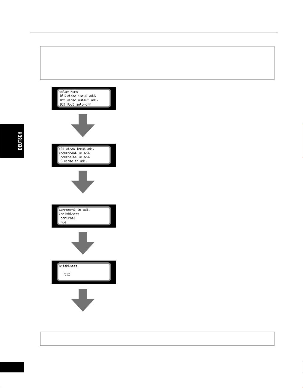
Kapitel 2 - Grundbetriebsarten
(Fortsetzung)
Nach der Auswahl des Menüelements mit Hilfe des Einstellrades drehen Sie das
3
Einstellrad, um die Einstellung dieses Menüelements zu ändern. Verfügt das ausgewählte
Menüelement über ein Untermenü, drücken Sie das Einstellrad, um das Untermenü
anzuzeigen.
Untermenü
Das Element wurde in Schritt 2 ausgewählt.
Drücken Sie das Einstellrad.
Drehen Sie zur Auswahl des Elements das Einstellrad.
Drücken Sie das Einstellrad.
32
98
Drehen Sie zur Auswahl des Elements das Einstellrad.
Drücken Sie das Einstellrad.
Drehen Sie zur Auswahl der Einstellung das Einstellrad.
* Drücken Sie die Taste MENU, wenn Sie die Einstellungen
abbrechen möchten.
Drücken Sie das Einstellrad.
Die Einstellung wurde geändert.
Drücken Sie die Taste MENU, um zum Hauptmenü zurückzukehren.
4
Page 97

Kapitel 2 - Grundbetriebsarten
.
3-2. Voreinstellen des Video-/Audioeingangs
4 Kombinationen des Video- und Audioeingangs* können unter “001 input preset 1” bis “004 input
preset 4” gespeichert und mit einem Tastendruck wieder aufgerufen werden.
* Zusätzlich zum Video- und Audioeingang können die Einstellung remote A und remote B (501 9P remote) und die DV-
Audioformateinstellung (201 DV audio encode) unter den Voreinstellungen 1 bis 4 gespeichert werden.
Speichern der Einstellungen
Drücken Sie die Taste VIDEO IN bzw. AUDIO IN, um die gewünschten Eingangseinstellungen
1
auszuwählen.
5&+8+&'1+0
%1/210'06
%1/215+6'
Drücken
Drücken Sie das Einstellrad oder die Taste MENU.
2
#7&+1+0
58+&'1
5&+
#'5'$7
$#.#0%'&
5&+#0#
&8ă5&+
Drücken
(Fortsetzung auf der nächsten Seite)
33
99
Page 98

Kapitel 2 - Grundbetriebsarten
.
.
.
(Fortsetzung)
Drehen Sie das Einstellrad, um die gewünschte Nummer (001 bis 004) auszuwählen und
3
drücken Sie das Einstellrad nochmals.
5&+#0#
&8ă5&+
Drehen und Drücken
• Sie können Einstellungen so vornehmen, dass nur einige voreingestellte Elemente aufgerufen
werden (nicht benötigte Elemente können übersprungen werden).
1. Drehen Sie das Einstellrad, wählen Sie “skip” und drücken Sie das Einstellrad.
2. Bestätigung “on” wurde ausgewählt. Drücken Sie das Einstellrad, um die Funktion SKIP zu
aktivieren.Wählen Sie “off”, wenn Sie die Funktion SKIP abbrechen möchten.
Kontrollieren Sie, dass “save current input” ausgewählt ist, und drücken Sie das
4
Einstellrad.
5&+#0#
&8ă5&+
34
100
Drücken
• Wenn Sie zurück zu Schritt 3 gehen möchten, wählen Sie “cancel” und drücken Sie das
Einstellrad.
Drehen Sie das Einstellrad, um die Option “save preset” anzuzeigen, und drücken Sie das
5
Einstellrad.
5&+#0#
&8ă5&+
Drehen und Drücken
Die Einstellung wird gespeichert und die Anzeige von Schritt 3 wird angezeigt.
• Wiederholen Sie die Schritte 2 bis 5, um weitere Einstellungen zu speichern.
Page 99

Kapitel 2 - Grundbetriebsarten
Wiederaufrufen der Einstellungen
Drücken Sie die Taste PRESET. Bei jeder Betätigung der Taste werden die
24'5'6
Einstellungen 1 bis 4 nacheinander aufgerufen.
Drücken
5&+8+&'1+0
%1/210'06
%1/215+6'
101
35
Page 100

Kapitel 2 - Grundbetriebsarten
3-3. Einstellen der Parameter
000 - 099 Einstellungen Audio-/Videoeingang
Voreinstellung Video-/Audioeingang -------------------------------
100 - 199 Einstellungen Videoeingang/-ausgang
Anpassungseinstellungen für Videoeingang ---------------------
Anpassungseinstellungen für Videoausgang --------------------
Einstellungen für automatisches Ausschalten für Videoausgang
Einstellung für automatisches Ausschalten für DV-Ausgang ---
Einstellung für Bildseitenverhältnis für DV-Ausgang -----------
Einstellung für Bildseitenverhältnis für S-Videoausgang ------
Videostandard-Einstellungen ----------------------------------------
Bildsynchronisator-Einstellung DV-Ausgang ---------------------
Synchronisationssignaleinstellungen für Videoausgang ------
Verzögerungseinstellung Videoausgang --------------------------
Verzögerungseinstellung Audioausgang --------------------------
001 input preset 1 -------------- 38
002 input preset 2 -------------- 38
003 input preset 3 -------------- 38
004 input preset 4 -------------- 38
101 video input adj. ----------- 39
102 video output adj ---------- 43
103 Vout auto-off --------------- 44
---
104 DVout auto-mute --------- 45
105 DV aspect info ------------- 46
106 Sout aspect info ----------- 47
107 video standard ------------- 48
108 DVout frame sync --------- 48
109 Vout ref. select ------------- 49
110 Vout ref. conf. -------------- 49
111 Vout audio delay ---------- 49
36
102
200 - 299 Einstellungen Audioeingang/-ausgang
Codiereinstellung DV-Audio ------------------------------------------
Symmetrischer Audio-Kopfraum (Referenzpegel) --------------
Eingangs-/Ausgangspegel für symmetrisches Audio ----------
Analoger Monitor-Audiomischausgang ----------------------------
Leitungsabschluss für Eingang für symmetrisches Audio (XLR)
300 - 399 Time Code-Einstellungen
Time Code-Einstellungen DV-Codierung -------------------------
DVITC-Einstellungen ---------------------------------------------------
201 DV audio encode --------- 50
202 audio headroom ---------- 50
203 audio level ----------------- 51
204 analog audio mon -------- 51
205 600 ohm term. ------------ 52
----
301 TC source ------------------- 52
302 VITC insert line ------------ 53
 Loading...