

Page 1

Adder II User Guide
M4046-9900-102
24 July 2014
Page 2

Notices
Copyright & Trademark Notice
Copyright © 2006–2014, Grass Valley. All rights reserved.
Belden, Belden Sending All The Right Signals, and the Belden logo are trademarks or
registered trademarks of Belden Inc. or its affiliated companies in the United States and
other jurisdictions. Grass Valley, Miranda, Adder II are trademarks or registered trademarks
of Grass Valley. Belden Inc., Grass Valley, and other parties may also have trademark rights
in other terms used herein.
Terms and Conditions
Please read the following terms and conditions carefully. By using Adder II documentation,
you agree to the following terms and conditions.
Grass Valley, a Belden Brand (“Grass Valley”) hereby grants permission and license to owners
of Adder II to use their product manuals for their own internal business use. Manuals for
Grass Valley products may not be reproduced or transmitted in any form or by any means,
electronic or mechanical, including photocopying and recording, for any purpose unless
specifically authorized in writing by Grass Valley.
A Grass Valley manual may have been revised to reflect changes made to the product
during its manufacturing life. Thus, different versions of a manual may exist for any given
product. Care should be taken to ensure that one obtains the proper manual version for a
specific product serial number.
Information in this document is subject to change without notice and does not represent a
commitment on the part of Grass Valley.
Warranty information is available in the Support section of the Grass Valley Web site
www.miranda.com).
(
Title Adder II User Guide
Part Number M4046-9900-102
Revision 24 July 2014
ii
Page 3

Table of Contents
1 Adder II System Overview . . . . . . . . . . . . . . . . . . . . . . . . . . . . . . . 1
About the Adder II system . . . . . . . . . . . . . . . . . . . . . . . . . . . . . . . . . . . . . . . . . . . . . . . . . . . . . . . . . 2
Adder II Components . . . . . . . . . . . . . . . . . . . . . . . . . . . . . . . . . . . . . . . . . . . . . . . . . . . . . . . . . . . . . . 3
Base Unit. . . . . . . . . . . . . . . . . . . . . . . . . . . . . . . . . . . . . . . . . . . . . . . . . . . . . . . . . . . . . . . . . . . . . . 3
Input/Output Modules . . . . . . . . . . . . . . . . . . . . . . . . . . . . . . . . . . . . . . . . . . . . . . . . . . . . . . . . 3
Front Panel. . . . . . . . . . . . . . . . . . . . . . . . . . . . . . . . . . . . . . . . . . . . . . . . . . . . . . . . . . . . . . . . . . . . 4
Rear Panel. . . . . . . . . . . . . . . . . . . . . . . . . . . . . . . . . . . . . . . . . . . . . . . . . . . . . . . . . . . . . . . . . . . . . 5
Laser Safety . . . . . . . . . . . . . . . . . . . . . . . . . . . . . . . . . . . . . . . . . . . . . . . . . . . . . . . . . . . . . . . . . . . . . . . 6
Laser Radiation. . . . . . . . . . . . . . . . . . . . . . . . . . . . . . . . . . . . . . . . . . . . . . . . . . . . . . . . . . . . . . . . 6
FCC Part A Manual Notice. . . . . . . . . . . . . . . . . . . . . . . . . . . . . . . . . . . . . . . . . . . . . . . . . . . . . . 6
CE Approved . . . . . . . . . . . . . . . . . . . . . . . . . . . . . . . . . . . . . . . . . . . . . . . . . . . . . . . . . . . . . . . . . . 6
2 Setting Up an Adder II System . . . . . . . . . . . . . . . . . . . . . . . . . . . 7
Installing and Configuring the Adder II System . . . . . . . . . . . . . . . . . . . . . . . . . . . . . . . . . . . . . 8
Power Requirements . . . . . . . . . . . . . . . . . . . . . . . . . . . . . . . . . . . . . . . . . . . . . . . . . . . . . . . . . . . . . . 9
Connections. . . . . . . . . . . . . . . . . . . . . . . . . . . . . . . . . . . . . . . . . . . . . . . . . . . . . . . . . . . . . . . . . . . . . .10
Fiber Connections . . . . . . . . . . . . . . . . . . . . . . . . . . . . . . . . . . . . . . . . . . . . . . . . . . . . . . . . . . . .10
Verifying Optical Link . . . . . . . . . . . . . . . . . . . . . . . . . . . . . . . . . . . . . . . . . . . . . . . . . . . . . . . . .11
Coaxial Connections. . . . . . . . . . . . . . . . . . . . . . . . . . . . . . . . . . . . . . . . . . . . . . . . . . . . . . . . . .12
Other Display messages . . . . . . . . . . . . . . . . . . . . . . . . . . . . . . . . . . . . . . . . . . . . . . . . . . . . . .12
Other Base Features . . . . . . . . . . . . . . . . . . . . . . . . . . . . . . . . . . . . . . . . . . . . . . . . . . . . . . . . . . . . . .13
Data Transport . . . . . . . . . . . . . . . . . . . . . . . . . . . . . . . . . . . . . . . . . . . . . . . . . . . . . . . . . . . . . . .13
+18/+24 Audio Level Reference Settings . . . . . . . . . . . . . . . . . . . . . . . . . . . . . . . . . . . . . .14
Signal Generator/Analyzer . . . . . . . . . . . . . . . . . . . . . . . . . . . . . . . . . . . . . . . . . . . . . . . . . . . .15
Analog TX and RX Modules . . . . . . . . . . . . . . . . . . . . . . . . . . . . . . . . . . . . . . . . . . . . . . . . . . . . . . .16
Analog TR Modules . . . . . . . . . . . . . . . . . . . . . . . . . . . . . . . . . . . . . . . . . . . . . . . . . . . . . . . . . .16
Analog TX Modules . . . . . . . . . . . . . . . . . . . . . . . . . . . . . . . . . . . . . . . . . . . . . . . . . . . . . . . . . .17
Analog RX Modules . . . . . . . . . . . . . . . . . . . . . . . . . . . . . . . . . . . . . . . . . . . . . . . . . . . . . . . . . .17
Local and Remote Gain Control of Analog Audio Modules . . . . . . . . . . . . . . . . . . . . . . . . .18
Selecting Channels to Modify . . . . . . . . . . . . . . . . . . . . . . . . . . . . . . . . . . . . . . . . . . . . . . . . .18
Setting Gains. . . . . . . . . . . . . . . . . . . . . . . . . . . . . . . . . . . . . . . . . . . . . . . . . . . . . . . . . . . . . . . . .19
Setting Phantom Voltage . . . . . . . . . . . . . . . . . . . . . . . . . . . . . . . . . . . . . . . . . . . . . . . . . . . . .20
AES 8 TX and RX Modules . . . . . . . . . . . . . . . . . . . . . . . . . . . . . . . . . . . . . . . . . . . . . . . . . . . . . . . .20
External AES Sync . . . . . . . . . . . . . . . . . . . . . . . . . . . . . . . . . . . . . . . . . . . . . . . . . . . . . . . . . . . .20
Intercom Modules . . . . . . . . . . . . . . . . . . . . . . . . . . . . . . . . . . . . . . . . . . . . . . . . . . . . . . . . . . . . . . .21
4-wire (balanced). . . . . . . . . . . . . . . . . . . . . . . . . . . . . . . . . . . . . . . . . . . . . . . . . . . . . . . . . . . . .21
Clear-Com . . . . . . . . . . . . . . . . . . . . . . . . . . . . . . . . . . . . . . . . . . . . . . . . . . . . . . . . . . . . . . . . . . .22
Nulling Procedure . . . . . . . . . . . . . . . . . . . . . . . . . . . . . . . . . . . . . . . . . . . . . . . . . . . . . . . . . . . 22
Powered (Wet) and Unpowered (Dry) Intercom Systems . . . . . . . . . . . . . . . . . . . . . . 23
RTS Telex. . . . . . . . . . . . . . . . . . . . . . . . . . . . . . . . . . . . . . . . . . . . . . . . . . . . . . . . . . . . . . . . . . . . .23
Installing/Removing Intercom Modules . . . . . . . . . . . . . . . . . . . . . . . . . . . . . . . . . . . . . . .24
iii
Page 4

Table of Contents
Data Transport Module . . . . . . . . . . . . . . . . . . . . . . . . . . . . . . . . . . . . . . . . . . . . . . . . . . . . . . . . . . .25
A2-DATA-8 Pinouts . . . . . . . . . . . . . . . . . . . . . . . . . . . . . . . . . . . . . . . . . . . . . . . . . . . . . . . . . . .25
Legacy Systems . . . . . . . . . . . . . . . . . . . . . . . . . . . . . . . . . . . . . . . . . . . . . . . . . . . . . . . . . . . . . . . . . .26
AES 16 input and output modules . . . . . . . . . . . . . . . . . . . . . . . . . . . . . . . . . . . . . . . . . . . .26
Clear-Com Intercom Modules (original version). . . . . . . . . . . . . . . . . . . . . . . . . . . . . . . .26
Diamondback . . . . . . . . . . . . . . . . . . . . . . . . . . . . . . . . . . . . . . . . . . . . . . . . . . . . . . . . . . . . . . . .27
Setting 75 Mbps operation . . . . . . . . . . . . . . . . . . . . . . . . . . . . . . . . . . . . . . . . . . . . . . . 27
IntercomCable Wiring . . . . . . . . . . . . . . . . . . . . . . . . . . . . . . . . . . . . . . . . . . . . . . . . . . . . . . . . . . . .28
4-Wire XLR 5-pin to two XLR 3-pin. . . . . . . . . . . . . . . . . . . . . . . . . . . . . . . . . . . . . . . . . . . . .28
Adder II to Clear-Com Matrix Plus Intercom Stations . . . . . . . . . . . . . . . . . . . . . . . . . . .29
Adder II to Clear-Com Matrix Plus Intercom Frame . . . . . . . . . . . . . . . . . . . . . . . . . . . . .30
3 Troubleshooting . . . . . . . . . . . . . . . . . . . . . . . . . . . . . . . . . . . . . . 31
Issues and Solutions . . . . . . . . . . . . . . . . . . . . . . . . . . . . . . . . . . . . . . . . . . . . . . . . . . . . . . . . . . . . . .32
Accessory List . . . . . . . . . . . . . . . . . . . . . . . . . . . . . . . . . . . . . . . . . . . . . . . . . . . . . . . . . . . . . . . . . . . .32
4 Specifications . . . . . . . . . . . . . . . . . . . . . . . . . . . . . . . . . . . . . . . . . 33
iv
Page 5

Adder II System Overview
This chapter provides an overview of the Adder II system by presenting the system
components and identifying the main component items.
About the Adder II system . . . . . . . . . . . . . . . . . . . . . . . . . . . . . . . . . . . . . . . . . . . . . . . . . . . . . . . . . . . . . 2
Adder II Components . . . . . . . . . . . . . . . . . . . . . . . . . . . . . . . . . . . . . . . . . . . . . . . . . . . . . . . . . . . . . . . . . . 3
Laser Safety . . . . . . . . . . . . . . . . . . . . . . . . . . . . . . . . . . . . . . . . . . . . . . . . . . . . . . . . . . . . . . . . . . . . . . . . . . . 6
1
Page 6

Adder II System Overview
About the Adder II system
About the Adder II system
The Adder II is a high-performance link for transporting analog and digital audio, two and
four wire intercoms, and various data formats using lightweight fiber optic cable. As a
modular system, the Adder II is highly configurable and scalable for use as a point-to-point
signal transport.
The Adder II features include:
• Up to 64 bi-directional channels of audio
• Four intercom module slots providing up to eight intercom channels
• Data and GPI capabilities
• Remote audio gain control
• Phantom mic power
• Industry leading latency and signal-to-noise specifications
An Adder II system is constructed from single RU frames that interface to a common
backplane, allowing the system to be sized to various requirements. Analog and AES TX and
RX frames can be combined with Intercom and Data frames to create an audio system that
is perfectly suited to your particular application. Whether you need 32 x 32 analog or 32
analog to 16 AES signals in just one direction, with or without intercoms and data, Adder II
gives you maximum flexibility.
Analog modules come in rows of 16 while AES modules are in rows of 8 and 16. In this way,
an AES TX can interface to an analog RX, thus bypassing the need for expensive D-A and AD converters. With ultra-low latency, delay is never an issue.
Analog TX modules feature preamps that allow 0, 10, 20, 30, 40, and 50 dB of gain
adjustments plus 12/48V phantom power via a convenient faceplate controls and LED
display. The Adder II includes remote control of these functions. With an optical budget
exceeding 25 dB, the Adder II can operate across the theater or across town.
Operation can be on one or two fibers or two standard coaxial cables. It is dual-wavelength
and can be easily converted to WDM single-fiber operation. GPI's and data channels are on
DB-9 connectors with RS-232, RS-422, and RS-485 ports. A built-in signal analyzer features
an LED bar graph and signal generator with three different tone frequencies and three level
choices in both the analog and digital domains.
The Adder II ships pre-configured and requires minimal onsite configuration.
2
Page 7
Adder II Components
Base Unit
Each end of an Adder system consists of at least two parts: One base frame with control unit
and one or more input/output (I/O) modules.
Base units are common to all Adder II’s no matter how large or small. This is the optical I/O
and the first building block of all systems. The base frame also has the on/off switch for the
system, the local gain controller, the data I/O’s, and to thetone generator/analyzer.
Input/Output Modules
Each Adder II can be configured with one to nine input/output modules depending upon
the frame size selected. All I/O modules are one RU high.
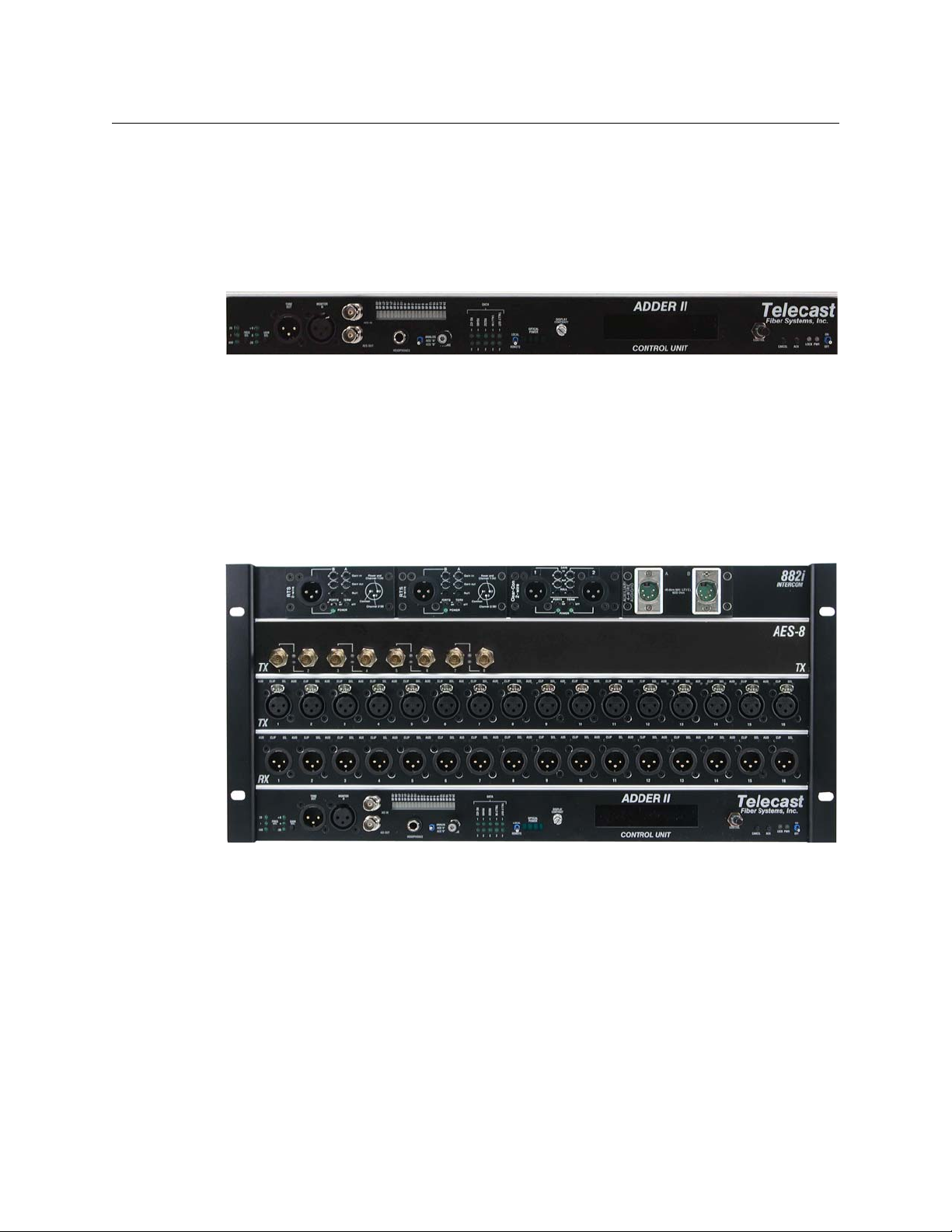
Adder II
User Guide
Fig. 1-1: Adder II Base Control Unit Front Panel
Fig. 1-2: Input and Output modules
The input /output modules, also referred to as “banks”, can be any of a range of input or
output modules including analog or digital audio and intercom.
• For analog signals, banks are 16 wide.
• For AES signals, banks are 8 wide (16 channels).
• Otherwise, the base is always bank 0.
The next row up is Bank 1, etc. as long as all signaling is analog. If intercom modules are
installed, this module would always be the top-most module.
Systems are delivered pre-configured and each frame will be a mirror image of the other, so
that if Bank 2 on one end is a TX module, then Bank 2 on the other end will be an RX
3
Page 8
Adder II System Overview
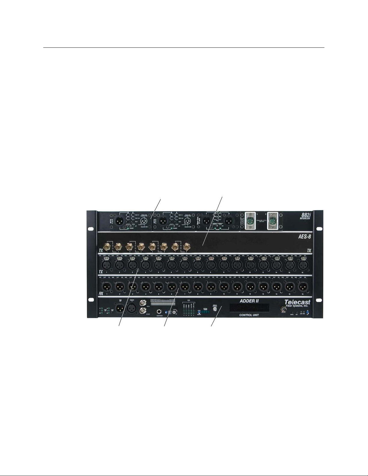
I/O Module, Bank 4
When Intercom module is installed it is
always in the top position
I/O Module
Bank 3
I/O Module
Bank 2
I/O Module
Bank 1
Base System Control Unit
(always lowest module)
Front Panel
module. It is possible to do analog to digital conversion between frames, so one end can be
analog and the other end can be digital/AES.
Each Adder II can accommodate one or two 12 VDC power inputs @ 3 Amps via 4-pin XLR or
terminal strip. Grass Valley’s ADAP-AC-04 is an acceptable external DC power supply.
Depending on version, there may be a third 12-18VDC input for intercoms.
If you require re-configuration of your Adder II system, it should be returned to Grass Valley.
Call our support department (see
Materials Authorization) number.
When removing the Adder II from the shipping boxes, check everything over for any
damage, including missing optical caps, bent metal or pins, and case scratches. Be assured
that the utmost care was taken in building and packing your Adder II, so report any damage
to the carrier and to Grass Valley.
Front Panel
Contact Us on page 37) and request an RMA (Return
4
Fig. 1-3: Adder II 5RU System Front Panel
Page 9
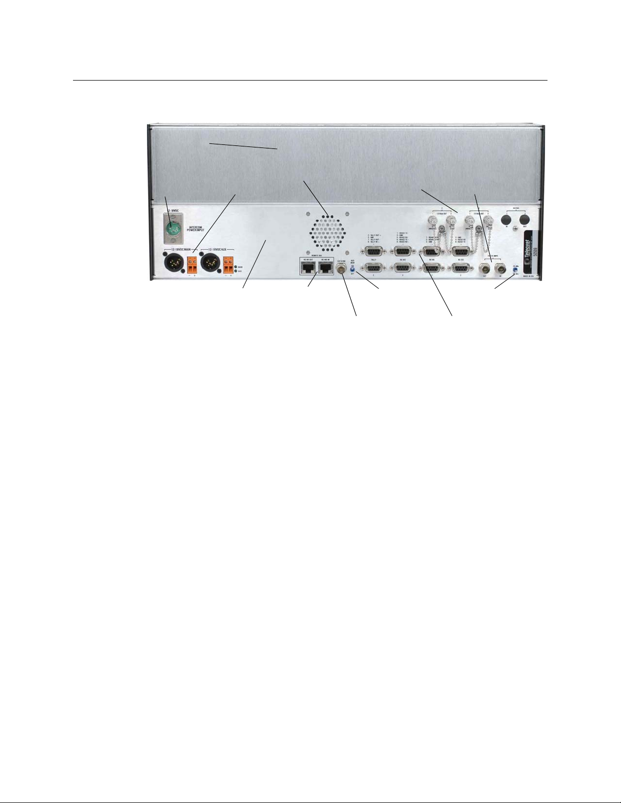
Rear Panel
Speaker on/off
switch
Speaker
Remote Bus
(not supported)
I/O Module, Bank 2 and up
Blank rears
Base System Control Unit
(always lowest module)
AES Sync In
GPIO and Serial
Data Ports
Redundant fiber System
interconnection
Coax system
interconnection
Audio level
standard
Redundant
DC Power
Intercom (wet)
Power
Adder II
User Guide
Fig. 1-4: Adder II 4RU System Rear Panel
5
Page 10

Adder II System Overview
Laser Safety
Laser Safety
WAR NIN G: Class 1 Laser. Do not stare into a connector port or fiber.
Laser Radiation
The unit is a CDRH Class 1 laser device. Although this means it is Eye Safe, you must avoid
looking directly at, or staring into, the laser beam located on an ST connector or on the end
of a fiber.
Infrared radiation is produced at the fiber connection port on the front of the unit and at
the end of unterminated optical fibers that are attached to this port. Avoid any direct
exposure to the light that comes from these sources.
Do not enable the laser when there is no fiber attached to the fiber connection port.
Do not attempt any type of service to this instrument other than what is instructed in this
manual. Refer any servicing needs to Grass Valley, a Belden Brand (see
page 37).
Contact Us on
FCC Part A Manual Notice
This equipment has been tested and found to comply with the limits for a Class-A digital
device, pursuant to part 15 of the FCC rules. These limits are designed to provide
reasonable protection against harmful interference when the equipment is operated in a
commercial environment. This equipment generates, uses, and can radiate radio frequency
energy and, if not installed and used in accordance with the instruction manual, may cause
harmful interference to radio communications. Operation of this equipment in a residential
area is likely to cause harmful interference, in which case the user must correct the
interference at their own expense.
CE Approved
This is a Class A product. In a domestic environment this product may cause radio
interference, in which case the user may be required to take adequate corrective measures.
6
Page 11

Setting Up an Adder II System
This chapter provides an overview of the Adder II components and features and explains
how to set them up.
Installing and Configuring the Adder II System . . . . . . . . . . . . . . . . . . . . . . . . . . . . . . . . . . . . . . . . . 8
Power Requirements . . . . . . . . . . . . . . . . . . . . . . . . . . . . . . . . . . . . . . . . . . . . . . . . . . . . . . . . . . . . . . . . . . 9
Connections . . . . . . . . . . . . . . . . . . . . . . . . . . . . . . . . . . . . . . . . . . . . . . . . . . . . . . . . . . . . . . . . . . . . . . . . . 10
Other Base Features . . . . . . . . . . . . . . . . . . . . . . . . . . . . . . . . . . . . . . . . . . . . . . . . . . . . . . . . . . . . . . . . . . 13
Analog TX and RX Modules . . . . . . . . . . . . . . . . . . . . . . . . . . . . . . . . . . . . . . . . . . . . . . . . . . . . . . . . . . . 16
Local and Remote Gain Control of Analog Audio Modules . . . . . . . . . . . . . . . . . . . . . . . . . . . . . 18
AES 8 TX and RX Modules . . . . . . . . . . . . . . . . . . . . . . . . . . . . . . . . . . . . . . . . . . . . . . . . . . . . . . . . . . . . 20
Intercom Modules . . . . . . . . . . . . . . . . . . . . . . . . . . . . . . . . . . . . . . . . . . . . . . . . . . . . . . . . . . . . . . . . . . . 21
Legacy Systems . . . . . . . . . . . . . . . . . . . . . . . . . . . . . . . . . . . . . . . . . . . . . . . . . . . . . . . . . . . . . . . . . . . . . . 26
IntercomCable Wiring . . . . . . . . . . . . . . . . . . . . . . . . . . . . . . . . . . . . . . . . . . . . . . . . . . . . . . . . . . . . . . . . 28
7
Page 12

Setting Up an Adder II System
Installing and Configuring the Adder II System
Installing and Configuring the Adder II System
To install and configure the Adder II system, follow these steps
1 Connect the power cables (see Power Requirements on page 9).
2 Connect the fiber and coaxial cables (see Connections on page 10).
3 Configure the data transport protocols (see Data Transport on page 13).
4 Configure the audio levels (see +18/+24 Audio Level Reference Settings on page 14).
5 Configure the Signal Generator (see Analog TR Modules on page 16).
6 Configure the Analog TR, TX, and RX modules (see Analog TX and RX Modules on
page 16).
7 Configure the Gain Control and Analog audio modules (see Local and Remote Gain
Control of Analog Audio Modules on page 18).
8 Configure the AES 8 TX and RX modules (see AES 8 TX and RX Modules on page 20).
9 Connect the Intercom modules (see Intercom Modules on page 21).
10 Interface with Legacy systems (see Legacy Systems on page 26).
11 Wire the Intercom cables (see IntercomCable Wiring on page 28).
8
Page 13
Power Requirements
Adder II Systems are largely “Plug and Play”, but there are several steps that must be
followed to ensure the reliability of your system. Providing reliable DC power and having
properly installed fiber optic cables are critical in maintaining reliable operation.
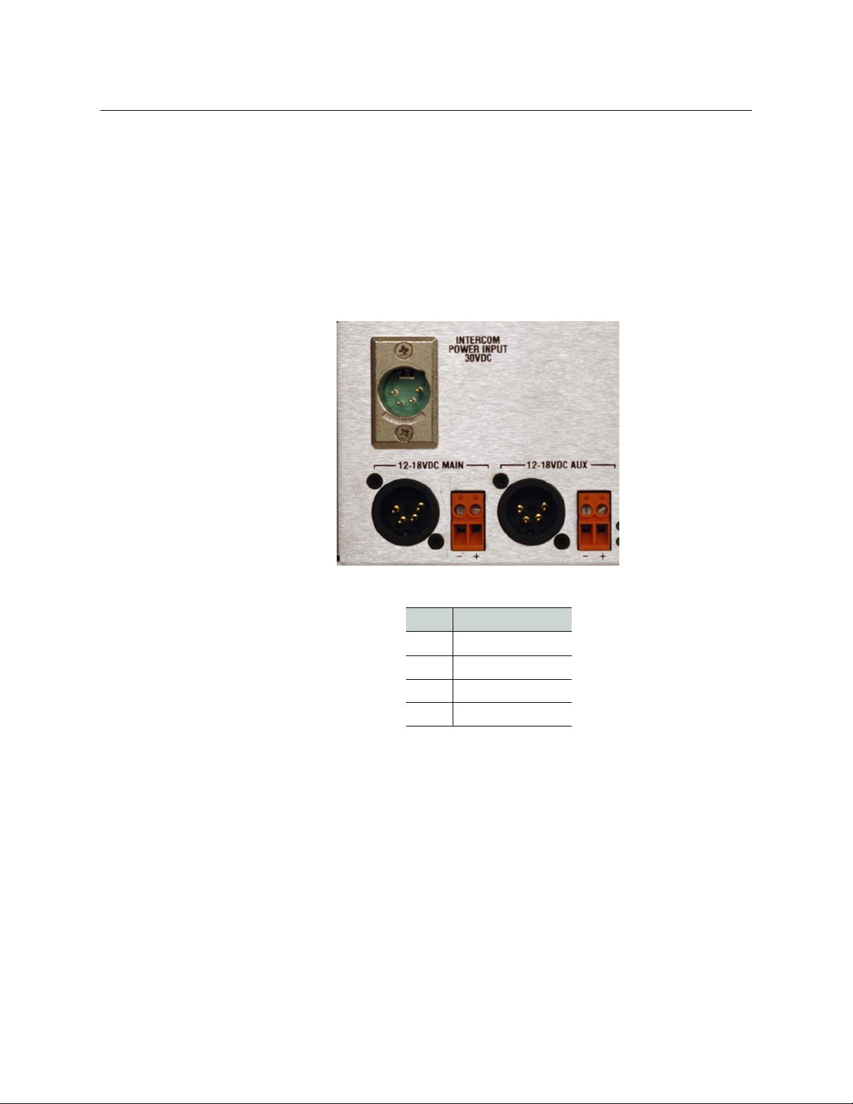
Any power supply used with your Adder II must provide a minimum of 3 amperes,
continuous, at 12 to 18 VDC. Power input is either through two 4-pin XLR-M connectors or
two terminal strips located on the left side of the rear panel that provide for full power
redundancy; see the table below for pinout and
outlets are within reach of their six-foot power cords.
Adder II
User Guide
Figure 2-1 for location. Be sure that AC
Fig. 2-1: Power Input Location
Pin Description
Pin 1 Ground
Pin 2 No connection
Pin 3 No connection
Pin 4 + VDC
Grass Valley’s ADAP-AC-04 meets the power requirements for Adder II, but any other
suitable DC supply may be used. Note that a fully loaded 125 Mb/sec system (64 bidirectional channels) can draw up to 5 Amps.
Once power is applied to the rear panel, the front-right mounted switch on the Base unit is
used to “power-on” the system.
• A Green LED near the input XLR’s indicates the presence of DC power.
• ARed LED next to the power switch on the front panel indicates that DC is present.
• A Green LED indicates that power is On.
Frames equipped with an 882i intercom bank will require it’s own 12-18 VDC power
connection to the INTERCOM POWER INPUT 30VDC above the MAIN input. The same wiring
conventions apply.
9
Page 14

Setting Up an Adder II System
1310 NM
Fiber I/O
1550 NM
Fiber I/O
Coaxial
I/O
Connections
Connections
Fiber Connections
WAR NIN G:
Never look directly into the unit of a connected optical fiber while any component of
the system is operating. Eye damage is possible.
Use the onboard optical power meter as a means of testing the optical signal at both
ends of your optical link.
An infrared laser diode that is coupled to the fiber generates the optical output from each
TX. User connections are made at bulkhead ST type connector s on the rear panel (see
Figure 2-2). You can use either single mode or multimode fiber, but take care to never mix
types of fiber in a given run. Once you employ WDMs into the system, their type will dictate
the type of fiber to use.
The RX inputs use an InGaAs pin diode and amplifier to convert the optical signal back into
an electrical signal.
Fig. 2-2: Fiber and Coax I/O Locations, Rear Panel
10
There are several ways to configure fiber in your Adder II systems:
• 1310 only: two fibers connect the IN’s of each to the OUT’s of the other in the 1310nm
optical window.
• 1550 only: two fibers connect the IN’s of each to the OUT’s of the other in the 1550nm
optical window.
• 1310 in one direction and 1550 in the other: requires only one fiber per link but
requires the addition of either an internal or an external WDM.
Page 15
In either scenario, you can make two links and the Adder II will automatically switch links
Optical Power
Display
LINK LED
should one fail. This solution offers complete and automatic optical redundancy (see
Figure 1-1).
Once you choose your method of connection, inspect the fiber ends and clean them with
Kim-Wipes that have been wet with pure isopropyl alcohol. Fingerprints or other dirt on the
optical connector end surfaces will reduce the received optical signal level.
Note that, unlike previous Adder systems, the fiber has priority in the Adder II. This means
that the system will always look for a link on the fiber ports first and then on the coaxial
ports. But also note that the coax path can be used as a redundant path.
Verifying Optical Link
Once both ends are powered up and your fiber connections are made, it becomes a simple
matter to verify how you are connected and the status of your optical link.
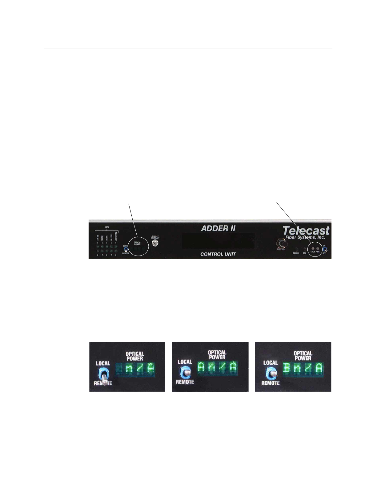
In the center of each Base faceplate there is a 4-Segment display labeled OPTICAL POWER.
The actual location is indicated in
Adder II
User Guide
Figure 2-3.
Fig. 2-3: Optical Power Display and LINK LED Location, Front panel
• With the switch to the REMOTE position, the display will indicate the optical power at
the other end of the link if the link is good. Otherwise it will display N/A as shown in
Figure 2-1.
• With the switch in the LOCAL position, the display will indicate both the INPUT that the
frame is linked to and the received optical power in dBm’s. The second two photos, in
Figure 2-4, show that the box is looking at both inputs A and B, but that there is no
optical power present. If the link is good, a value for the optical power would be
indicated. An optical power reading between -5 and -22 dBm will be optimal.
Fig. 2-4: Optical Power Display – various conditions
In addition to the optical power readings, a Green LOCK LED on the right side of the Base
faceplate (next to the power switch) indicates that the frame is properly linked. A Red LED
indicates no link/lock (see
Figure 2-2).
11
Page 16

Setting Up an Adder II System
Coaxial Connections
If the switch is on the REMOTE position and the frame on the other side of the link is not
locked, the display will indicate NoLk.
Coaxial Connections
Figure 2-2 above shows the position of the COAXIAL I/O (labeled 75/125 MBPS) on the rear
panel of the Base. As an alternative to using fiber, the Adder II system can support full
operation on two coaxial cables of up to 300m (1000 ft) in length.
When not linked, the system looks for an active link on the fiber and COAX ports. In this way
(and unlike previous Adder versions), the coax canserve as a redundant path in conjunction
with one or both of the optical paths.
Fig. 2-5: Link LOCK Status LEDs
Connection is simply a 75 Ohm coaxial cable from the OUT on each frame to the IN on the
other.
The COAX ports are also used (the Adder II must in 75 Mbps mode) when paired with bidirectional DiamondBack II’s or DiamondBack 4x4’s. See
more information.
Other Display messages
A fiber or coax break (depending on configuration) or loss of signal from one end of the link
to the other will result in the message Communication Lost.
The message Illegal configuration or loopback will appear if you pair two chassis that
have a TX module in one chassis for which there is no corresponding RX module in the
other.This message will also appear if you loop back the fiber or coax so that the chassis is
talking to itself. The message goes away as soon as you press any button.
Legacy Systems on page 26 for
12
Page 17

Other Base Features
Data Transport
The Adder II Base units have built-in data support for:
• 2 Tally (GPI)
•2 RS-422
•2 RS-485
•2 RS-232
Adder II
User Guide
Fig. 2-6: Data Connectors on Base Rear Panel
The pin-outs for the DB-9 connectors are described on the rear panel above the connectors
Tab le 2-1(see Figure 2-7 for position). Note that these pinouts are non-standard,so
and in
you will require custom cables.
Fig. 2-7: Data LEDs
Front panel LED indicators will flash with data traffic or stay constant Green in the case of a
closed (shorted) Tally/GPI.
The Adder II accepts and multiplexes up to two RS-232, two RS-422, and two RS-485 digital
data signals and two remote relay closures. The other side of the link then receives the
13
Page 18

Setting Up an Adder II System
+18/+24 Audio Level Reference Settings
aggregate data, restores the digital signals and provides switch closures. The number of
data channels is fixed and independent of the number of audio channels in the assembly.
Both data input and output are accomplished on the same connector.
Digital signal connections are made via 9-pin D connectors; see Figure 2-6. The connection
specifications are listed in Tab le 2-1; note that these pinots do not conform to standard
serial pinouts and custom cable wiring will typically be required when connecting to thirdparty devices. Several interconnection cables are described in
page 28. A 110 Ohm terminating resistor placed across the balanced inputs may be needed
if input cable lengths are in excess of six feet.
PIN Conns 1 & 2 Conns 3 & 4 Conns 5 & 6 Conns 7 & 8
1 422 TX (-) 485 TX/RX (-)
2 GPI Out (+) 485 TX/RX (+)
3 GND GND GND GND
4 232 RX
5 422 RX (-)
6 422 TX (+) 232 TX
7 GPI Out (-)
8 GPI In (+)
IntercomCable Wiring on
9 422 RX (+)
Table 2-1: Data pin-outs
Contact closure input is activated by pin 8 on contact to ground or to a TTL logic 0 signal
level. Contact closure output is established by an isolated, normally open, dry contact built
onto the Main PC Board. The eight digital I/O connectors are AMP 747905-2, D-sub female
or equivalent.
Additional data ports can be added in groups of 8 with A2-DATA-8 I/O strips.
+18/+24 Audio Level Reference Settings
The rear-panel +18/+24 switch toggles the Input analog audio encoder that can be set at
either 18db or 24db. This will determine the level where analog input audio will clip. It is
not necessary that both ends of the link be set the same.
14
Fig. 2-8: +18/24 Switch Location
Page 19

Signal Generator/Analyzer
The integrated audio signal generator/analyzer is a convenient way to confirm signal
presence for both analog and digital (AES) audio signals.
Tone for analog signals is accessed via the XLR-Male connector TONE OUT using standard
XLR audio cable. Three different frequencies (20Hz, 400HZ and 1k Hz) are available at three
different audio levels (-20, 0 and +8 db) to allow easy channel verification/identification.
Selection is via the small buttons on the lower right side of the base unit (see
For digital signals, tone (Line Level @ 1Khz) is available on the AES OUT BNC.
A built-in speaker is accessed via XLR-Female connector MONITOR IN (for analog signals)
using standard XLR audio cable. Digital signals are monitored via the AES IN BNC. The
speaker is directly associated with the audio level bar graph that will indicate audio levels
from -33 to +24 db. Speaker volume is controlled via the VOLUME knob.
Adder II
User Guide
Figure 2-10).
Fig. 2-9: Analog/Digital Signal Generator/Analyzer
In order to monitor analog and AES signals properly, payattention to the switch to the left
of the VOLUME knob.
Fig. 2-10: AUD MON On/Off Switch
When monitoring only analog signals, the switch can remain in the top ANALOG position.
For AES signals, A refers to the left component and B to the right component of a given AES
signal. Be sure you are monitoring the correct “side” of your digital signals.
Use of the headphone jack (1/4” standard) automatically disables the external speaker.
There is also a switch on the rear of the frame for disabling the speaker.
15
Page 20

Setting Up an Adder II System
2
1
2
3
Input (female) Output (male)
Line Level Inputs and Outputs
Analog TX and RX Modules
Analog TX and RX Modules
The modules in your system are factory-configured for your specific requirements. It is not
recommended to try to change the configuration.
Analog audio I/O is via 3-pin XLR connectors with industry standard wire locations (see
table below). Analog TX and RX modules are in groups of 16 channels.
The XLR connectors are located on the front panel of each module.
• On the input modules, XLR connectors are female Neutrik type NC3FPR-H.
• On the output modules, XLR connectors are male Neutrik type NC3MG-H (refer to
Figure 2-7).
PIN SIGNAL
1 Ground
2 Balanced I/O (+)
3 Balanced I/O (-)
Fig. 2-11: XLR Connectors on TX and RX Modules
Analog TR Modules
Adder II Analog TR modules have eight line level inputs and eight line level outputs as on
the same single module as shown in
There are no gain pr phantom adjustments for the 8x8 module. LEDs show AUD Signal
presence and CLIP only.
16
Figure 2-12.
Fig. 2-12: Analog TR Module
Page 21

Analog TX Modules
Adder II Analog TX modules are 16 inputs wide as shown in Figure 2-13 .
• AUD: blinks Green with audio presence
• CLIP: glows Red when audio levels are clipping
• SEL: glows Blue to show that the channel is selected for adjustment
Adder II
User Guide
Fig. 2-13: Analog TX Module and Analog TX LED indications
Each input accepts a mono audio signal on a male XLR. Input levels can be mic or line level
and gains as well as phantom mic power can be set from the bottom base unit.
Input parameters can be set for individual channels or entire modules/banks.
Analog RX Modules
The analog RX modules feature 16 XLR-M outputs. The module faceplate is shown in
Figure 2-14.
Each output has 3 associated LEDs as shown in Figure 2-14 .
• AUD: blinks Green with audio presence
• CLIP: glows Red when audio levels are clipping
• SEL: glows Blue to show that the channel is selected for adjustment
Fig. 2-14: Analog RX Module and Analog RX LED indications
Each output provides a mono audio signal on a male XLR. Levels can be set at either side of
the link.
17
Page 22

Setting Up an Adder II System
Local and Remote Gain Control of Analog Audio Modules
Local and Remote Gain Control of Analog Audio Modules
Analog gains are adjusted via a knob and two buttons on the Base Unit. The following
selection describes procedures for making input adjustments. Control location is indicated
Figure 2-15. Note that adjustments for an audio path can be set from either end of the
in
link.
Fig. 2-15: Local gain controller/selector
The process starts by pressing the ACK button and then dialing the control knob indicate
the proper “Bank” or module. All modules except the base and 882i can be addressed. An
attempt to address an audio path that does not contain an analog TX will result in the
message gain ”[FIXED]”. An example of this might be an AES TX connected to an analog RX.
Remember that the Base Control Unit occupies Bank 0, so that the first module up is Bank 1,
the second is Bank 2, etc. Once you have found the analog module that requires
adjustment, press the ACK button to acknowledge that you are in position to select
channels to modify.
You may press the CANCEL button at any time to start the process over from the beginning.
Once you have selected the proper Bank, you can now opt to select one channel or make a
universal change to all of the channels in that Bank.
Selecting Channels to Modify
By using the knob to scroll to Chan:ALL, you can change gain and phantom voltage for all
16 inputs in one step.
and blinking. LED’s above the channels will remain illuminated to show that a change has
been made from unity gain or no phantom voltage.
Figure 2-13 shows that the SEL LEDs for all 16 inputs are illuminated
18
Fig. 2-16: Starting point
Page 23

Adder II
User Guide
If you wish to only change a parameter for a single input, rotate the knob until the desired
channel is indicated in the display AND the proper SEL LED is flashing over the
input/inputs.
Fig. 2-17: All Channels selected
Once you are satisfied with your selection, press the ACK button. The SEL LED will remain
blinking as long as you are working on that particular input/inputs and will remain on to
show that some parameter for that channel has been changed.
Figure 2-18 shows that we
will be working on Channel 2.
Setting Gains
Once you have selected a channel (or channels) to work on, you can adjust gain and
phantom power settings.
Once the ACK button is pressed to select an input or inputs, GAIN will flash in the display.
You may now use the control knob to toggle through six gain options; 0db, +10db, +20db,
+30db, +40db and +50db. Once the desired gain level is displayed, press the ACK button to
set.
Fig. 2-18: Channel 2 selected
Figure 2-14 shows the display when adjusting gain for channel 2.
Fig. 2-19: Setting Gain
Figure 2-14 shows that the gain was set to +50db.
19
Page 24

Setting Up an Adder II System
AES LEDs
Setting Phantom Voltage
Setting Phantom Voltage
Once the gain change is acknowledged, Volts will flash. Use the control knob to toggle
between the three phantom voltage options: 0V, 12V, and 48V. Once the desired voltage
level is displayed, press the ACK button to set.
phantom power to 48V.
Note that there will be a short delay while the inputs are updated with the new settings.
The Adder II system will remember any gain or phantom settings between power ups.
If a frame is linked to a different frame, the settings from the analog TX modules will be
restored on both ends of the system. The message Synchronizing With Remote Unit will
appear as settings are restored during start-up or following a power or fiber failure. And loss
of link will result in the display of Communication Failure.
Figure 2-14 shows that we are setting the
Fig. 2-20: Setting Phantom Voltage
The Adder II will remember all settings following a power failure.
AES 8 TX and RX Modules
The TX and RX AES 8-channel modules feature BNC connectors for input and output. A
representative module is shown in
Each channel has a single green LED that indicates signal presence. All levels and other
signal parameters are as defined by the AES-3 specification (user bits are NOT maintained).
Modules come in 8 TX and 8 RX.
External AES Sync
Figure 2-21 .
Fig. 2-21: AES-8 TX and AES LEDs
20
Input AES audio is synchronized by local internal clock or can be synchronized to an
external source connected to the BNC connector located on the rear panel. Any AES digital
signal with or without audio (null word okay) can be used for this purpose.
Page 25

Intercom Modules
The 882i Intercom module can house up to 4 ADDR-AUX modules:
•Balanced 4-wire
•Clear-Com 2-wire
• RTS/Telex compatible 2-wire
Intercoms can be of any type in any location in the assembly. However, for proper operation
of the intercom channels, the same placement order must be followed at the other side of
the system. A 2-wire system can be interconnected with a 4-wire system at another Adder
II, but not all intercom functions will work (for example, calling).
4-wire (balanced)
4-wire Auxiliary (balanced) intercoms use an individual 5-pin XLR on each of the two
channels in each module (see
table. Intercom Module Gain is 0 dB.
Adder II
User Guide
Fig. 2-22: 882i Intercom Modules
Figure 2-21). XLR pin functions are given in the following
PIN FUNCTION IMPEDENCE SIGNALS
1 Ground
2 Input (+) 600 Ohm input Line: +8 dBm
3 Input (-) 600 Ohm input Mic: -32 dBm
4 Out (+) >=600 Ohm load +8 dBm
5 Out (-) >=600 Ohm load +8 dBm
Fig. 2-23: Intercom Module: 4-Wire Auxiliary (balanced)
21
Page 26

Setting Up an Adder II System
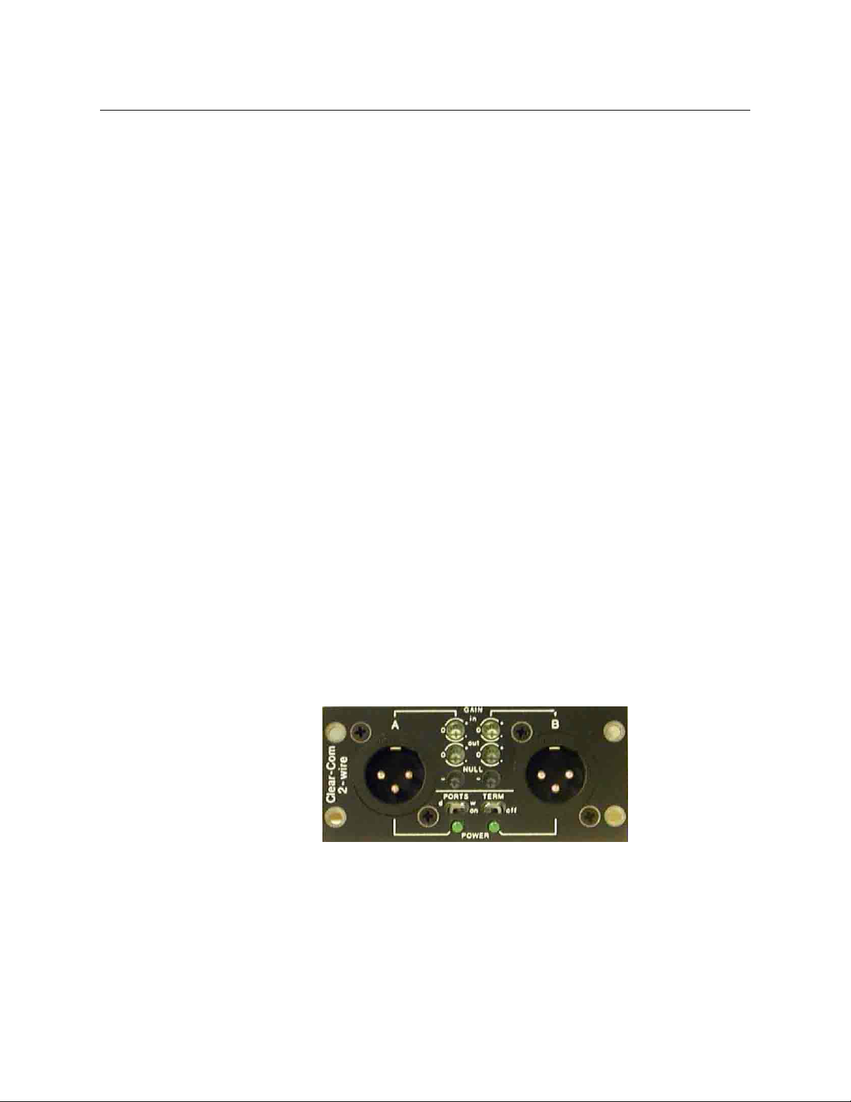
Clear-Com
Clear-Com
Clear-Com intercom modules have a 3-pin XLR connector for each of the A and B channels.
This Grass Valley module fully supports the Clear-Com signaling protocol and signal levels.
The Clear-Com Intercom Connections are listed in the table below.
Fig. 2-24: Clear Com module
Pin Description
Pin 1 Ground
Pin 2 +VDC Power
Pin 3 Power
• The units null by plugging in a 1/8-inch (3.5mm) stereo headset (not a TS-1) into the
connector located in the center of the unit and then adjusting the top set of pots for
optimum null.
• The second set of pots, labeled GAIN, adjust the receive gain for that channel +/-3db.
•The POWER switch controls whether 30VDC is applied to beltpacks and/or remote
stations that might be plugged into the module.
•The MODE switch should always be set to CC for Clear-Com intercom systems.
Nulling Procedure
Note: A stereo audio headset and a tweeker are needed to null these modules.
Inserting the 1/8” sub-mini stereo headset jack into the Clear-Com module turns on a tone
that nulls the system. It is important that the nulling procedure be done when all beltbacks
and other interfaces are in place. If you add additional beltpacks, it is likely that the nulling
procedure should be repeated.
As indicated on the module faceplate, the right ear serves Channel A and the left ear serves
Channel B. Do not listen to both ears at the same time as this will not allow you to carefully
discern the tone.
22
While listening to the right side, turn the adjustment pot on the top left above the mini
headset jack. The goal is to eliminate and/or minimize the nulling tone. Once you have
gotten the adjustment so that the tone is as quiet as possible, then change ears and do
Channel B while using the top right adjustment pot.
Page 27

RTS Telex
Adder II
User Guide
Powered (Wet) and Unpowered (Dry) Intercom Systems
The Grass Valley Clear-Com interface is compatible with powered or unpowered belt packs
as well as fixed equipment . Switch the Module to WET (down) when you want to use the
Adder to provide power to one or more intercom beltpacks and/or remote intercom
stations. The module will provide adequate power for approximately 4 beltpacks or 2
remote stations, or a combination thereof.
If you are supplying power to your intercom system externally with an intercom power
supply or “Master” intercom station, switch the Module to DRY (up). Many more belt packs
can be added if powered externally. Refer to your intercom manufacturer’s documentation
for additional system details.
Note: When powering a Clear-Com intercom system with an external power supply,
be sure to set the AdderII intercom module to “dry” to prevent noise, oscillation or
motor-boating.
RTS modules provide a two-channel intercom on a single 3-pin XLR connector. This module
fully supports the RTS signaling protocol and signal levels.
RTS channel operation is optimized by the use of front panel adjustments as shown in
Figure 2-25 and listed below.
• Input Gain, ± 10 dB
•Output Gain, ± 10 dB
•Null
Fig. 2-25: Intercom Module: RTS Telex
The following table lists the RTS Telex pin numbers and intercom connections. Switches are
also provided for the channel pair for:
• Dry unpowered (d), or Wet powered (w) PORTS
• 200 Ohm ON or OFF terminations TERM
Pin Description
Pin 1 Ground
Pin 2 +VDC Power & Chan 1 Audio
Pin 3 Chan 2 Audio
23
Page 28

Setting Up an Adder II System
Installing/Removing Intercom Modules
The interface is compatible with powered or unpowered belt packs, as well as fixed
equipment. You may power up to five belt packs with each intercom module. Refer to your
intercom manufacturer’s documentation for additional system details.
For operation with a belt pack, adjust the following:
• set the PORTS to w (powered)
• the TERM to ON
• center each of the INPUT gain, OUTPUT gain, and NULL controls
Readjust these controls to optimize performance as required.
Installing/Removing Intercom Modules
Before attemping any module exchange,the Adder II should be powered OFF .
Two multi-conductor cable harnesses are built into the Adder II and run behind the module
locations. These cables connect the intercom modules to power and signal sources. There
are AMP-MTA type connectors for each module on this harness; the connector fits all
module types.
• Signal is 8-pin
•Power is 2-pin
To change an intercom module in the assembly:
1Turn the power OFF.
2 Remove the four screws that hold the module in the frame.
3 Gently pull the intercom module away from the frame until you can see and remove
the two cable harnesses.
4 Replace with new module and reconnect in reverse order.
5Turn the power ON.
Fig. 2-26: Replacing Intercom Modules
24
Page 29

Data Transport Module
A2-DATA-8 module
Close up of ports on the A2-DATA-8 module
The A2-DATA-8 I/O module allows you to add additional RS-485 serial data ports to your
Adder II. The ports can be added in groups of 8. Each A2-DATA-8 module uses 8 transmit
and 8 receive channels on the fiber multiplex (the same as the A2-AM8x8-0 bidirectional
analog audio module would use.) The baud rate is automatically set to match the data
source with a maximum data rate of 112 kbps.
Adder II
User Guide
For each port there are 232, 422 and GPI I/O connections, however you can use only one
data input at a given time. The input port automatically determines the incoming signal
type. When the input is a serial data signal, the corresponding output on the other Adder II
system appears on both the RS232 and RS422 pins of the data connector.
You can achieve GPI input trigger by either tying pin 1 to ground or pin 6 to V+ (CMOS, TTL,
nominally up to +12VDC). Inputs are protected from over-voltagesand input impedance is
5k.
A2-DATA-8 Pinouts
Pin Function
1 RS422 In-, GPI-
2 GPO Relay NC
3 Ground
4 RS232 Out
5 RS422 Out +
6 RS422 In+, GPI +, RS232 In
7 GPO Relay NO
8 GPO Relay Common
9 RS422 Out-
Shroud Ground
Fig. 2-27: A2-DATA-8 module
25
Page 30
Setting Up an Adder II System
Legacy Systems
Legacy Systems
The Adder II is the latest audio over fiber multiplexer from Grass Valley, a Belden Brand
Several versions of Adder and other audio multiplexers preceded the Adder II, and some
Adder II modules are no longer manufactured. This section is for reference should you be
using this manual with an earlier system or components.
AES 16 input and output modules
16 input, 16 output, and 8 in/8-out AES modules were previously offered for the Adder II.
Each 16 Channel AES module uses two “Banks” on the base unit backplane. For modules
with 16 AES signals, for addressing purposes, the first 8 AES signals will be equivalent to one
bank and the second 8 AES signals will be addressed as the next bank. To ensure proper
channel mapping when converting to and from analog or AES, it is important to remember
that 16 channel AES’s occupy two banks.
If a 16 port AES module is used at one end, at the other end it would connect to another 16
port AES modules, two 8-port AES modules, or two 16-port analog audio modules.
Clear-Com Intercom Modules (original version)
Earlier Clear-Com intercom modules were different that the current version with different
configuration. The setup of the earlier model is described below.
Clear-Com channel operation is optimized by the use of the front panel adjustments shown
Figure 2-28 and listed below:
in
•Input Gain, ±10 dB
•Output Gain, ±10 dB
•Null
Switches are also provided for the channel pair for:
• PORTS: Dry unpowered (d), or Wet powered (w)
• TERM: 200 Ohm on or off terminations
Fig. 2-28: Intercom Module: Clear-Com
The original Clear-Com interface is compatible with powered or unpowered belt packs as
well as fixed equipment. You may power up to three belt packs with each intercom module
from the internal power supply.
26
Many more belt packs can be added if powered externally. Refer to your intercom
manufacturer’s documentation for additional system details.
For operation with a belt pack, adjust as follows:
Page 31

Readjust these controls to optimize performance as required.
The Base Unit PCB75/125 Mbs Switch
Diamondback
The Adder II is compatible with earlier Diamondback multiplexers. The Coax ports are used
and the Adder II must be set for 75 Mbps mode when paired with bi-directional
DiamondBack II’s or DiamondBack 4x4’s. When used with a Diamondback, the Adder II is
limited to 32 channels in each direction.
Setting 75 Mbps operation
Adder II
User Guide
• set the PORTS to w (powered)
• set the TERM to ON
• center each of the INPUT gain, OUTPUT gain and NULL controls
Fig. 2-29: The Base Unit PCB and 75/125 Mbs Switch
Figure 2-29 shows the Base Unit PCB. Each module is attached to its appropriate cable
header on this board. In addition, all optical and coaxial I/O, data functions and power
are handled here.
Figure 2-29 also shows the 75/125Mb switch that has a bearing on
overall system functionality.
The large switch (in the yellow circle) toggles between two different system data transport
rates.
• In 75Mb/sec mode, the system is Diamondback II compatible, but is capable of only 32
bi-directional channels plus Intercom and data.
• In 125Mb/sec mode, the system is no longer Diamondback II compatible, but can
accommodate up to 64 channels, bi-directional, plus data, and intercom.
27
Page 32

Setting Up an Adder II System
Pin 1 SIGNAL GND GND1Pin 2 Input (+)2Pin 3 Input (-)3Pin 4 Output (+)4Pin 5 Output (-)
5
XLR5F
Cha sis Cha sis Ground
600 Ohm Input
>= 600 Ohm
load
XLR 5 Pin Female Plug- Input
5
XLR FEM ALE
(solde r side )
3
1
2 4
Pin 1 SIGNAL GND GND
1
Pin 2 Input (+)2Pin 3 Input (-)3Pin 4 Output (+)4Pin 5 Output (-)
5
XLR5M
Chasis Chasis Ground
XLR 5 Pin Male Socket - Output
>= 600 Ohm load
600 Ohm Input
●●●
●
●●●
●
2
Pin 2 Audio In (+)3Pin 3 Audio In (-)1Pin 1 Signal Ground
CASE Chasis Ground
2
3
1
XLR MALE
(solder side)
2
Pin 2 Audio Out (+)3Pin 3 Audio Out (-)1Pin 1 Signal Ground
CASE Chasis Ground
2
3
1
XLR MALE
(solder side)
●●●
●
●
●
XLR5F
Female Plug
XLR3M
Male Plug
Shrink Wrap Blue label with
"???"
A B
4-Wir e
AUXILL IARY
AUDIO I / O
XLR3F
Female Plug
XLR3M
Male Plug
XLR3F
Female Plug
Audio In
Aud io I n
Audio Out
Audio Out
IntercomCable Wiring
IntercomCable Wiring
4-Wire XLR 5-pin to two XLR 3-pin
Fig. 2-30: 4-Wire XLR 5-pin to two XLR 3-pin
28
Page 33

Adder II to Clear-Com Matrix Plus Intercom Stations
Intercom Station
Adder 2
RS-422 dat a send (+ ) 1
RS-422 dat a send (-) 2
Audio s end (+ ) 3
Audio recei ve (+) 4
Audio recei ve (-) 5
Audio s end (-) 6
RS-422 dat a receive (+) 7
RS-422 dat a receive (-) 8
1GND
2Audio In (+)
3 Audi o In (-)
4 Audio Out (+ )
5 Audio Out (-)
XLR FEMALE
5F PLUG
(sol der side)
3
1 5
2 4
5 RS-422 Input (-)
4 RS-422 Input (+)
3GND
6 RS-422 Output (-)
1 RS-422 Output (+)
RJ45 Modular 8-pin
18
1
8
9-pin D Male
XLR FEMAL E
5F PLUG
PUSH
Telecast
Fiber Systems, Inc.
ADDER II
CONTROL UNI T
TONE
OUT
MONITOR
HEADPHONES
VOLUME
ANALOG
AES “A”
AES “B”
LOCAL
REMOTE
GAIN
SEL
FREQ
SEL
20
1
400
+50-20
AES IN
AES OUT
1
2
1
2
1
2
1
2
1
2
OPTICAL
POWER
LOCK PWR
CONTROL
ON
OFFCANCEL ACK
TALLY OUT
TALLLY IN
RS232
RS485
RS422
DATA
24 dB
21 dB
18 dB
15 dB
15 dB
12 dB
9 dB
6 dB
3 dB
0 dB
-3 dB
-6dB
-9 dB
-12 dB
-15 dB
-18 dB
-21 dB
-24 dB
-27 dB
-30 dB
-33 dB
1
ETH PWR
By
Tel ecast
Fi ber Syst ems , Inc.
Adder I I T X16L
2 3 4 5 6 7 8 9 10 11 12 13 14 15 16
PUSHPUSHPUSH PUSH PUSHPUSHPUSH PUSHPUSH PUSH PUSH PUSHPUSH PUSH PUSH PUSH
1
ETH PWR
By
Tel ecast
Fiber Systems, Inc.
Adde r II RX16
2 3 4 5 6 7 8 9 10 11 12 13 14 15 16
A
4-Wire
AUXILLIARY
AUDIO I/O
B
A
4-Wire
AUXILLIARY
AUDIO I/O
B
A
4-Wire
AUXILLIARY
AUDIO I/O
B
A
4-Wire
AUXILLIARY
AUDIO I/O
B
Adder II
User Guide
Fig. 2-31: Adder II to Clear-Com Matrix Plus Intercom Stations
29
Page 34

Setting Up an Adder II System
Int er com Frame
Adder 2
RS-422 dat a rec ei ve (+) 1
RS-422 dat a rec ei ve (-) 2
Audio receive (+) 3
Audio send (+) 4
Audio send (-) 5
Audio receive (-) 6
RS-422 data s end (+) 7
RS-422 data s end (-) 8
1GND
2 Audio In (+)
3 Audio In (-)
4 Audio Out (+ )
5 Audio Out (-)
XLR FEM ALE
5F PLUG
(solder side )
3
1 5
2 4
5 RS-422 Input (-)
4 RS-422 Input (+)
3GND
6 RS-422 Output (-)
1 RS-422 Output (+ )
RJ45 Modular 8-pin
18
1
8
9-pin D Male
XLR FEMAL E
5F PLUG
PUSH
Telecast
Fiber Systems, Inc.
ADDER II
CONTROL UNIT
TONE
OUT MONITOR
HEADPHONES
VOLUME
ANALOG
AES “A”
AES “B”
LOCAL
REMOTE
GAIN
SEL
FREQ
SEL
201400
+50-20
AES IN
AES OUT
1
2
1
2
1
2
1
2
1
2
OPTICAL
POWER
LOCK PWR
CONTROL
ON
OFF
CANCEL ACK
TALLY OUT
TALLLY IN
RS232
RS485
RS422
DATA
24 dB
21 dB
18 dB
15 dB
15 dB
12 dB
9 dB
6 dB
3 dB
0 dB
-3 dB
-6dB
-9 dB
-12 dB
-15 dB
-18 dB
-21 dB
-24 dB
-27 dB
-30 dB
-33 dB
1
ETHPWR
By
Tel ecast
Fiber Systems, Inc.
Adde r II TX16L
2 3 4 5 6 7 8 9 10 11 12 13 14 15 16
PUSHPUSHPUSH PUSH PUSHPUSHPUSH PUSHPUSH PUSH PUSH PUSHPUSH PUSH PUSH PUSH
1
ETH PWR
By
Tel ecast
Fiber Systems, Inc.
Adde r II RX1 6
23 45 67 8910111213141516
A
4-Wire
AUXILLIARY
AUDIO I/O
B A
4-Wire
AUXILLIARY
AUDIO I/O
B
A
4-Wire
AUXILLIARY
AUDIO I/O
B
A
4-Wire
AUXILLIARY
AUDIO I/O
B
Adder II to Clear-Com Matrix Plus Intercom Frame
Adder II to Clear-Com Matrix Plus Intercom Frame
Fig. 2-32: Adder II to Clear-Com Matrix Plus Intercom Frame
30
Page 35

Troubleshooting
This chapter list common issues with the Adder II system and provides solutions to these
issues.
Issues and Solutions . . . . . . . . . . . . . . . . . . . . . . . . . . . . . . . . . . . . . . . . . . . . . . . . . . . . . . . . . . . . . . . . . . 32
Accessory List . . . . . . . . . . . . . . . . . . . . . . . . . . . . . . . . . . . . . . . . . . . . . . . . . . . . . . . . . . . . . . . . . . . . . . . . 32
31
Page 36

Troubleshooting
Issues and Solutions
Issues and Solutions
Symptom Possible Cause Corrective Action
No Power No power adapter
No Optical Link Bad Fiber
Bad power adapter
Mispatched fiber
Lossy fiber or dirty fiber
connections
Replace AC-DC Supply with a known
functional one.
Verify that there is a link at both ends via
optical power meter and LINK LED.
Clean ends and/or reduce the number
of interconnections to achieve optical
power within range (-5 to -22 dBm).
Accessory List
The following accessories are available from Grass Valley:
• Portable optical power meter
• Fiber and coaxial cables built to custom lengths
Signal Generator/
analyzer not working
Overall audio levels
too high or low
Clipping audio Too muc h gain Ensure that gains for each channel are
Speaker turned OFF Activate speaker using rear panel
switch.
Frame not set to match
audio console
Use +18/+24 switch on rear panel to set
level at which audio will clip.
set properly for the input signal.
32
Page 37

Specifications
General
Data Transmission Method........................ Digital Time Division Multiplexing (TDM)
Aggregate Data Rate.............................................................. 75 or 125 Mbps (selectable)
Latency......................................... ~1 millisecond plus 5 microseconds per km of fiber
Interchannel Phase Delay........................................................................<1 degree at 1kHz
Optical Fiber Connectivity
Operating Wavelength.................................................................... 1310 nm and 1550 nm
Fiber connector.................................................................................................................ST type
Recommended fiber type .................................................................................. Single mode
................................................................................ 2-fiber system 1-fiber (WDM) system
TX Output into cable...................................................................................... -7 dBm -8 dBm
RX Sensitivity..................................................................................................-32 dBm -31 dBm
Link budget (maximum) ................................................................................... 23 dB - 25 dB
Recommended distance limit...................... 20 km (singlemode), 5 km (multimode)
Coax Connectivity
Impedance...................................................................................................................... 75 Ohms
Recommended cable.........................................................................................Belden 1694A
Connector..................................................................................................................................BNC
Distance limitation.............................................................................305 meters (1000 feet)
Audio, Analog...........................................................................................................
Analog Audio Connectors.............................. 3-pin XLR (female on TX & male on RX)
Transmission Method..................................................... Digital, 24-bit, 48 ksamples/sec
Input Impedance, Analog.....................................................................10k Ohms balanced
Output Impedance ...................................................................................30 Ohms balanced
Line Input Setting............................................................................................+24 dBm (peak)
Maximum Input Level...................................................................................................................
Unity Gain (0 dB)...................................+18 dBM peak / +24 dBm peak (selectable)
+10 dBM Input Setting ........................................... + 8 dBM peak / +14 dBm peak
+20 dBm Input Setting............................................- 2 dBM peak / + 4 dBm peak
+30 dBm Input Setting............................................- 12 dBM peak / - 6 dBm peak
+40 dBm Input Setting........................................... - 22 dBM peak / - 16 dBm peak
+50 dBm Input Setting........................................... - 32 dBM peak / - 26 dBm peak
Maximum Output Level
(from 30 Ω balanced)................+18 dBm @ 1kHz, 600 ohm, switchable to +24 dBm
Frequency Response (@ 8 dBm).......................................±0.2 dB from 20 Hz to 20 kHz
Total Harmonic Distortion + Noise......... <0.05% from 20 Hz to 20 kHz (@ +8 dBm)
33
Page 38

Specifications
.....................................................................................................<0.01% at 1 kHz (@ +18 dBm)
Intermodulation Distortion (SMPTE) . <0.04%, 60 Hz + 3 kHz mixed 4:1 @ +8 dBm
Signal to Noise Ratio (A-weighted) .............. >95 dB, 20 Hz -20 kHz, ref. to +18 dBm
Audio, Digital ...........................................................................................................
AES/EBU Inputs and Outputs .................................................. unbalanced, 75-ohm BNC
Transmission MethodAES/EBU Digital Audio Pair conforming to AES3 specifications
External Sync......................................................................................................BNC, rear panel
Sample Rate......................................................................................................................... 48 kHz
User Bits ................................................................................................................Not supported
Serial Data Transmission.........................................................................................
Data Connector..............................................................................................9-pin Female "D"
RS232 ............................................................................................ ±8 Vp-p level, 20 kBps max.
RS422/RS485 ...............................................................Balanced TTL levels, 150 kBps max.
Jitter.............................................................................................................. <330 ns (3.07 MS/s)
Latency............................................................................ ~ 0.90 us plus 5 us per km of fiber
Intercom (882i module)...........................................................................................
Total intercom channels.............................................................................................................8
Intercom compatibility (per module)......................................................................................
................................................................. 4-Wire: 2 balanced, non-powered, 5-pin XLR-M
............................................................. Clear-Com: 2 unbalanced, powered, 3-pin XLR-M
...............................................RTS: 1 unbalanced, powered, dual-channel, 3-pin XLR-M
Signal-to-noise ratio (A-weighted)............................................................................. >90 dB
Frequency response ......................................................... +1/-3 dB, 80Hz-20kHz, +8 dBm
Contact Closure / GPIO ............................................................................................
Connector..............................................................................2 9-pin Female "D" connectors
Input contacts....... Normally High TTL 1 level (remote contact open/open circuit)
.............................................. Short to ground TTL 0 (remote contact closed/triggered)
Output contacts............................ Form 1A SPST, "Normally Open" isolated contacts
Switch Voltage Rating............................................................................................. 50V AC/DC
Switch Current Rating.................................................................................................... 500 mA
Maximum Carry Current Rating .................................................................................500 mA
Contact Resistance.....................................................................................................< 0.5 Ohm
Mechanical/Electrical/Environmental....................................................................
2RU ................................................ 19" wide x 7.75" deep x 3.5" high, 8 lbs (3.5 kg)
3RU ................................................19" wide x 7.75" deep x 5.25" high, 9 lbs (3.5 kg)
4RU ................................................19" wide x 7.75" deep x 7.0" high, 10 lbs (3.5 kg)
5RU ............................................... 19" wide x 7.75" deep x 8.75" high, 11 lbs (3.5 kg)
6RU ............................................... 19" wide x 7.75" deep x 10.5" high, 12 lbs (3.5 kg)
7RU ...............................................19" wide x 7.75" deep x 12.25" high, 13 lbs (3.5 kg)
Power Connector.................................................... 4-pin XLR (male) x2, screw terminals
Input Voltage Range....................................................................... 12 to 18 VDC, 4.5A max.
Power Consumption
34
Page 39

(per end, all channels at full level)...................................................... 45 watts maximum
Temperature Range ............................................................................................. -40° to +60°C
Humidity Range ...........................................................................0 to 90% non-condensing
Adder II
User Guide
35
Page 40

Specifications
36
Page 41

Grass Valley Technical Support
For technical assistance, please contact the Grass Valley Technical Support center nearest
you:
Contact Us
Americas
Office hours: 9:00 a.m. – 9:00 p.m. (EST)
Telephone: 1-800-224-7882
Fax: +1 514 335 1614
E-mail: support@miranda.com
Europe, Middle East, Africa, UK
Office hours: 9:00 a.m. – 6:00 p.m. (GMT)
Telephone: +44 118 952 3444
Fax: +44 118 952 3401
E-mail: eurotech@miranda.com
France
Office hours: 9:00 a.m. – 5:00 p.m. (GMT+1)
Telephone: +33 1 55 86 87 88
Fax: +33 1 55 86 00 29
E-mail: eurotech@miranda.com
Corporate Head Office
Asia
Office hours: 9:00 a.m. – 6:00 p.m. (GMT+8)
Telephone: +852 2539 6987
Fax: +852 2539 0804
E-mail: asiatech@miranda.com
China
Office hours: 9:00 a.m. – 6:00 p.m. (GMT+8)
Telephone: +86 10 5873 1814
E-mail: asiatech@miranda.com
Malaysia
Telephone: +60 3 2247 1808
EMERGENCY After Hours (Global)
Toll Free: 1-800-224-7882 (US and Canada)
Telephone: +1 514 333 1772
Grass Valley
3499 Douglas-B.-Floreani
St-Laurent, Quebec H4S 2C6
Canada
Telephone: +1 514 333 1772
Fax: +1 514 333 9828
Web: www.miranda.com
 Loading...