

Page 1

DENSITÉ series
ADC-1722
Dual Analog Audio to AES Converter
Guide to Installation and Operation
M696-9900-400
17 Apr 2013
3499 Douglas-B.-Floreani
St-Laurent, Québec, Canada H4S 1Y6
Tel. 514-333-1772
Fax. 514-333-9828
www.miranda.com
© 2013 Miranda Technologies
Miranda Technologies
Page 2
GUIDE TO INSTALLATION AND OPERATION
Electromagnetic Compatibility
This equipment has been tested for verification of compliance with FCC Part 15, Subpart B
requirements for Class A digital devices.
NOTE: This equipment has been tested and found to comply with the limits for a Class A digital device,
pursuant to part 15 of the FCC Rules. These limits are designed to provide reasonable protection against
harmful interference when the equipment is operated in a commercial environment. This equipment
generates, uses, and can radiate radio frequency energy and, if not installed and used in accordance
with the instruction manual, may cause harmful interference to radio communications. Operation of this
equipment in a residential area is likely to cause harmful interference in which case the user will be
required to correct the interference at his own expense.
This equipment has been tested and found to comply with the requirements of the EMC directive
2004/108/CE:
• EN 55022 Class A radiated and conducted emissions
• EN 61000-3-2 Harmonic current emission limits
• EN 61000-3-3 Voltage fluctuations and flicker limitations
• EN 61000-4-2 Electrostatic disc harge immunity
• EN 61000-4-3 Radiated electromagnetic field immunity – radio frequencies
• EN 61000-4-4 Electrical fast transient immunity
• EN 61000-4-5 Surge immunity
• EN 61000-4-6 Conduc ted i m m unit y
• EN 61000-4-11 Voltage-dips, short-interruption and voltage variation immunity
2/22 | ADC-1722
Page 3

GUIDE TO INSTALLATION AND OPERATION
Table of Contents
1 ADC-1722 Dual Analog Audio to AES Converter ................................................................... 5
1.1 Introduction ......................................................................................................................................... 5
1.2 Features .............................................................................................................................................. 5
1.3 Functional Diagram ............................................................................................................................. 6
2 Installation ............................................................................................................................... 6
2.1 Unpacking ........................................................................................................................................... 6
2.2 Installation in the Densité frame .......................................................................................................... 6
2.3 Rear Panel Connections ..................................................................................................................... 7
3 Operation ................................................................................................................................. 8
3.1 Control options .................................................................................................................................... 8
3.2 Card-Edge Status LED........................................................................................................................ 8
3.3 Local control using the Densité frame control panel ........................................................................... 9
3.3.1 Overview ................................................................................................................................ 9
3.3.2 Menu for local control ............................................................................................................. 9
3.3.3 Explanation of Menu Parameters ......................................................................................... 11
3.4 Remote control using iControl ........................................................................................................... 13
3.4.1 The Levels panel .................................................................................................................. 16
3.4.2 The Input panel .................................................................................................................... 16
3.4.3 The Output panel ................................................................................................................. 17
3.4.4 The MSB panel .................................................................................................................... 17
3.4.5 The Alarms panel ................................................................................................................. 18
3.4.6 The Info panel ...................................................................................................................... 20
4 Specifications ........................................................................................................................ 22
ADC-1722 | 3/22
Page 4

GUIDE TO INSTALLATION AND OPERATION
Americas
Office hours:
Telephone:
Fax:
E
Asia
Office hours:
Telephone:
Fax:
E
Europe, Middle East, Africa, UK
Office hours:
Telephone:
Fax:
E
China
Telephone:
E
France
Office hours:
Telephone:
Fax:
E
EMERGENCY After Hours (Global)
Toll Free:
Telephone:
Miranda Technical Support
For technical assistance, please contact the Miranda Technical Support center nearest you:
9:00 a.m. – 9:00 p.m. (EST)
1-800-224-7882
+1 514 335 1614
-mail: support@miranda.com
9:00 a.m. – 6:00 p.m. (GMT)
+44 118 952 3444
+44 118 952 3401
-mail: eurotech@miranda.com
9:00 a.m. – 5:00 p.m. (GMT+1)
+33 1 55 86 87 88
+33 1 55 86 00 29
-mail: eurotech@miranda.com
Visit our website at www.miranda.com
9:00 a.m. – 5:00 p.m. (GMT+8)
+852 2539 6987
+852 2539 0804
-mail: asiatech@miranda.com
+86 10 5873 1814
-mail: asiatech@miranda.com
1-800-224-7882 (US and Canada)
+1 514 333 1772
4/22 | ADC-1722
Page 5

GUIDE TO INSTALLATION AND OPERATION
1 ADC-1722 Dual Analog Audio to AES Converter
1.1 Introduction
The ADC-1722 is a high-quality, 24-bit, analog audio to digital converter which allows conversion of two
stereo analog audio signals to AES type digital signals. Sampling rates can be set to 32, 48 or 96 kHz. AES
outputs can be locked an external reference signal. An internal digital EBU tone generator facilitates
alignment of audio levels. User-defined channel identification data may be encoded in the AES status bits.
An input audio signal status is also available indicating the input signal presence or overload. The ADC-1722
is compatible with both AES3 and AES-3id digital audio standards and is housed in a Densité frame, 2 or 3
RU. A single or double-width rear panel is required.
1.2 Features
• (1 or 2) balanced analog audio inputs
• external reference loop input (Word Clock or AES3-id DARS)
• (2 or 2x2) AES digital audio outputs
• Balanced AES3 or unbalanced AES3-id outputs
• 24-bit A to D conversion
(16, 20 or 24 bits output word length)
• 32, 48 and 96 kHz sampling rates
(Optional VCXO for 44.1/88.2 kHz)
• -96 to +12 dB of level adjustment (in 0.5 dB steps)
• 0 dBFS selectable (0 to +28 dBu, 1 dB steps)
• Internal EBU tone generator
• No signal delay threshold adjustable
• Overload detection and reporting
• Settings and adjustments through frame control panel
• Status LED and remote reporting
• Provides output to Monitoring Switching Bridge option (MSB-1121)
o Not supported for Assy# starting at 0696-1200-400
• Supports REF-1701 or REF-1801 reference card
o jumper selectable for Assy #0696-1200-2xx
o automatic for Assy# starting at 0696-1200-400
ADC-1722 | 5/22
Page 6
GUIDE TO INSTALLATION AND OPERATION
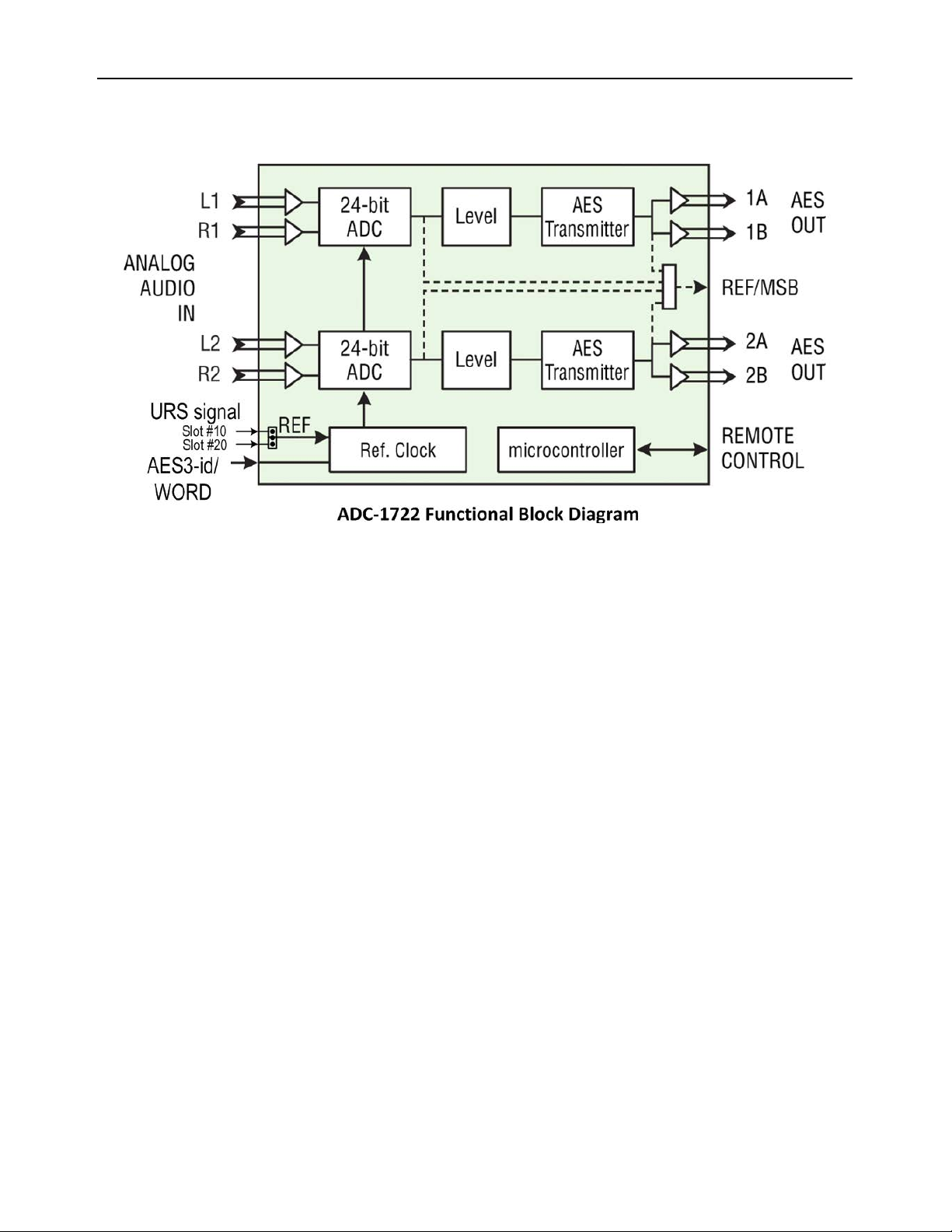
1.3 Functional Diagram
2 Installation
2.1 Unpacking
Make sure the following items have been shipped with your ADC-1722. If any of the following items are
missing, contact your distributor or Miranda Technologies Inc.
• ADC-1722 Dual analog audio to AES converter
• ADC-1722-DRP-75 or ADC-1722-DRP-110 Dual Rear Panel, or ADC-1722-SRP-75 or ADC-1722-SRP-110
Single Rear Panel (see figure)
2.2 Installation in the Densité frame
The ADC-1722 and its associated rear connector panel must be mounted in a DENSITÉ frame. It is not
necessary to switch off the frame’s power when installing or removing the panel. See the DENSITÉ Frame
manual for detailed instructions for installing cards and their ass oc iate d rear pan el s.
When a double–width rear panel is used, the module must be installed in the right-most of the two slots
associated with the rear panel in order to mate with the rear-panel connectors. If it is placed in the wrong slot,
the front panel LED will flash red. Move the card to other slot for correct operation. No damage will result to
the card should this occur.
If a card is placed in the wrong slot, its front panel LED will flash red. Move the card to other slot for correct
operation. No damage will result to the card should this occur.
Attention:
For cards with an Assy# 0696-1200-2xx only – if a reference card is installed in the DENSITÉ frame, e.g. a
REF-1701 in slot #20 or a REF-1801 in slot #10, you have to set the JP1 jumper accordingly. Please refer to
the silkscreen on the card for the jumper position. This selection is automatic with an Assy# starting at 06961200-400.
6/22 | ADC-1722
Page 7
GUIDE TO INSTALLATION AND OPERATION
ADC-1722-
DRP-110
ADC-1722-
DRP-75
ADC-1722-110-DRP
AES OUT
ANALOG IN
+ G – + G –
+ G –
+
–
2 LEFT
2 RIGHT
2A
ANALOG IN
AES OUT
1 LEFT
1 RIGHT
1A
+ G –
+ G –
ANALOG IN
+ G – + G –
+ G –
2 LEFT
2 RIGHT
2A
ANALOG IN
1 LEFT
1 RIGHT
1A
+ G –
+
–
+ G –
1B 2B
1B 2B
A REF IN
A REF IN
AES OUT
AES OUT
ADC-1722-
SRP-110
+ G – + G –
ANALOG IN
AES OUT
1 LEFT
1 RIGHT
1A
+ G –
+ G –
1B
A REF IN
ADC-1722-
SRP-75
+ G - + G -
ANALOG IN
1 LEFT
1 RIGHT
1A
1B
A REF IN
AES OUT
G G
ADC-1722-75-DRP
ADC-1722-75-SRP
ADC-1722-110-SRP
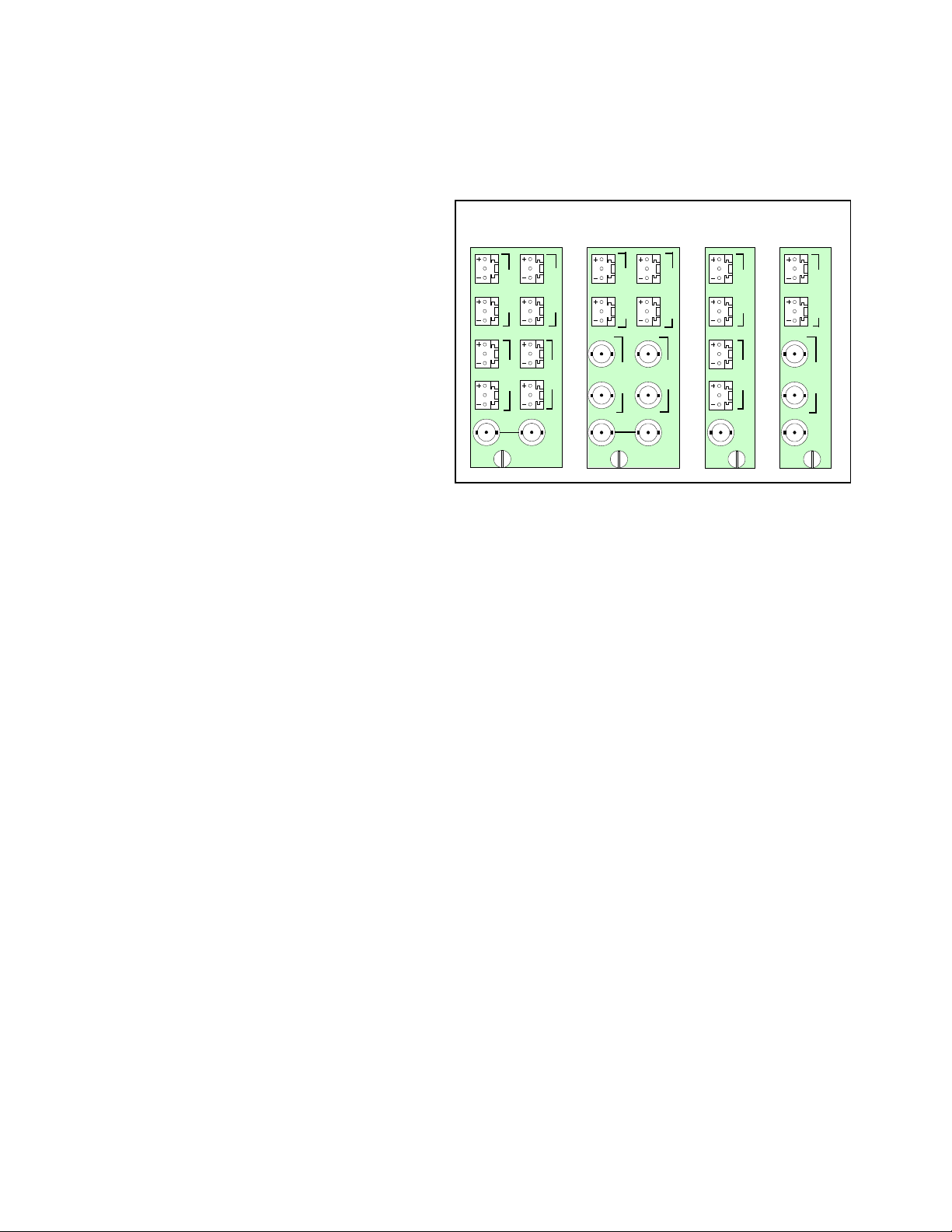
Rear Panel Connections
Four different rear panels are available for the ADC-1722. Their layouts are shown in the figure, and the
signal connections are detailed below.
• The double-width rear panels support
dual stereo audio channels
• The single-width rear panels support a
single stereo audio channel.
The rear panel connections are as follows:
ANALOG AUDIO IN (stereo pairs, left & right)
Connect two or four analog audio signals.
AES OUT – digital audio outputs
These connectors carry the output AES signal
(one or two channels depending on the rear).
Connector type depends on impedance:
• Weco for AES3 (bala nced outp ut ) 110Ω
• BNC for AES-3id (unbalanced output) 75Ω
A REF IN – audio reference signal (with loop-through on the double rear only)
Connect an AES-3id or wor d clock signal to one of the connectors.
ADC-1722 | 7/22
Page 8

GUIDE TO INSTALLATION AND OPERATION
Error Condition
Green
Yellow
Red
Flashing
Red
3 Operation
3.1 Control options
The ADC-1722 can be controlled in two different ways:
• The local control panel and its push-buttons can be used to move through a menu of parameters and
adjust parameter values (see section 3.3).
• Miranda’s iControl system can be used to access the card’s operating parameters from a remote
computer, using a convenient graphical user interface (GUI). (see section 3.4)
3.2 Card-Edge Status LED
The status monitor LED is located on the front card-edge of the ADC-1722, and is visible through the front
access door of the DENSITÉ frame. This multi-color LED indicates the status of the ADC-1722 by color, and
by flashing/steady illumination.
The chart shows how the various error conditions that can be flagged on the ADC-1722 affect the LED status.
• If a cell is gray, the error condition cannot cause the LED to assume that status
• If more than one LED status is possible for a particular error condition, the status is configurable.
See Section 3.4.5 for details.
• The factory default status is shown by a
The LED will always show the most severe detected error status that it is configured to display, and in the
chart error severity increases from left to right, with green representing no error/disabled, and flashing red the
most severe error.
LED Status
No errors
No signal
No external reference
No frame reference
Tone
Overload
Mute
Missing or incorrect rear panel
If the LED is Flashing Yellow, it means that the card is selected for local control using the Densité frame’s
control panel. See Section 3.3 for details.
8/22 | ADC-1722
Page 9

GUIDE TO INSTALLATION AND OPERATION
Select
Status
Status LED
SELECT button
ADC-1722
3.3 Local control using the Densité frame control panel
3.3.1 Overview
Push the SELECT button on the ADC-1722 card edge
to assign the local control panel to operate the ADC-
1722. Use the control panel buttons to navigate through
the menu, as described below.
All of the cards installed in a Densité frame are
connected to the frame’s controller card, which handles
all interaction between the cards and the outside wor ld .
There are no operating controls located on the cards
themselves. The controller supports remote operation
via its Ethernet ports, and local operation using its
integrated control panel.
The local control panel is fastened to the front of the
CPU-ETH2 controller card, and when installed can
be accessed by opening the front door of the frame
The panel consists of a display unit capable of
displaying two lines of text, each 16 characters in
length, and five pushbuttons .
The panel is assigned to operate any card in the
frame by pushing the SELECT button on the front
edge of that card.
• Pushing the CONTROLLER button on the
control panel selects the Controller card
itself.
• The STATUS LED on the selected card flashes yellow.
The local control panel displays a menu that can be navigated using the four pushbuttons located beneath
the display. The functionality of the pushbuttons is as follows:
[+] [–] Used for menu navigation and value modification
[SELECT] Gives access to the next menu level. When a parameter value is shown, pushing this button
once enables modification of the value using the [+] and [–] buttons; a second push confirms the
new value
[ESC] Cancels the effect of parameter value changes that have not been confirmed; pushing [ESC]
causes the parameter to revert to its former value.
Pushing [ESC] moves the user back up to the previous menu level. At the main menu, [ESC]
does not exit the menu system. To exit, re-push the [SELECT] button for the card being
controlled.
If no control is operated for 30 seconds, the controller reverts to its normal standby status, and the selected
card’s STATUS LED reverts to its normal operating mode.
3.3.2 Menu for local control
The ADC-1722 has operating parameters that may be adjusted locally at the controller card interface.
ADC-1722 | 9/22
Page 10

GUIDE TO INSTALLATION AND OPERATION
FPGA FAILURE, REAR PANEL ERROR, INTERNAL, EXTERNAL, FRAME, CARD EDGE
0 dBFS SETTING
0, 1, 2, ..., 24
CONFIGURE ALARM
NO EXTERNAL
REF
ALARM LEVEL
ALARM REPORT
NONE, GPI
GREEN, YELLOW, RED, FLASH RED
OVERLOAD
ALARM LEVEL
ALARM REPORT
NONE, GPI
GREEN, YELLOW, RED, FLASH RED
NO SIGNAL
ALARM LEVEL
ALARM REPORT
NONE, GPI
GREEN, YELLOW, RED, FLASH RED
TONE
ALARM LEVEL
ALARM REPORT
NONE, GPI
GREEN, YELLOW, RED, FLASH RED
MUTE
ALARM LEVEL
ALARM REPORT
NONE, GPI
GREEN, YELLOW, RED, FLASH RED
ALARM LEVEL
ALARM REPORT
NONE, GPI
GREEN, YELLOW, RED, FLASH RED
NO FRAME REF
TONE
CHANNEL 1&2
CHANNEL 1
OFF, EBU
CHANNEL 2
LEVEL
CHANNEL 1&2
CHANNEL 1
LEFT & RIGHT
LEFT
-96, ..., 0, …, +12
RIGHT
CHANNEL 2
MUTE
CHANNEL 1&2
CHANNEL 1
LEFT & RIGHT
LEFT
OFF, ON
RIGHT
CHANNEL 2
OUTPUT SAMPLE RATE
32k, 48k, 96k
NO SIGNAL DELAY
0, ..., 15, ..., 255
SIGNAL THRESHOLD
-48, -42, -36, -30, -24
MONITORING
INPUT 1 L&R, INPUT 2 L&R,
OUTPUT 1 L&R, OUTPUT 2 L&R
STATUS
CHANNEL 1
CHANNEL 2
UC=Vxxx, FPGA=Vxxx
MODULE
OVERLOAD (L,R,L&R), MUTE(L,R,L&R), TONE, NO SIGNAL(L,R,L&R), ALL OK
(dB)
(dBu)
OUTPUT WORD LENGTH
CHANNEL 1&2
CHANNEL 1
16, 18, 20, 24
CHANNEL 2
(bits)
CHANNEL STATUS
CHANNEL 1&2
CHANNEL 1
ORIGIN
DESTINATION
4 ASCII characters
CHANNEL 2
(s)
(dBu)
RESTORE Vxxx
FIRMWARE VERSION
FACTORY DEFAULT
• Press the SELECT button on the ADC-1722 front card edge to assign the Densité frame’s local
control panel to the ADC-1722
• Use the keys on the local control panel to step through the displayed menu to configure and adjust
the ADC-1722.
10/22 | ADC-1722
Page 11

GUIDE TO INSTALLATION AND OPERATION
3.3.3 Explanation of Menu Parameters
by channel Parameters so marked can be set for either Channel 1, Channel 2 or both channels together.
{STATUS}
MODULE: displays the status of the different board alarms.
FPGA FAILURE Faulty programmable component.
REAR PANEL ERROR Indicates an absence of the rear panel or an incompatibility between the module and the rear
panel. The STATUS led turns on flashing red.
INTERNAL No valid reference signal connected.
EXTERNAL The signal connected at the rear BNC is selected as reference for the card.
FRAME The internal frame signal is selected as reference for the card; for Assy# 0696-1200-2xx only
the JP1 jumper has to be set accordingly with the reference generator card installed in the
Densité frame.
CARD EDGE The signal coming from an adjacent module via the rear panel is selected as reference for the
card (only when used with the AMX-1101 rear panel).
CHANNEL (1/2): displays the status of the corresponding analog input channel.
OVERLOAD (L/R) Indicates an internal signal level higher than –0.5 dBFS.
MUTE (L/R) Indicates a muted channel.
TONE indicates the tone generator is active.
NO SIGNAL (L/R) Indicates an internal signal level lower than the selected threshold during a user-defined
period.
ALL OK indicates an absence of alarms.
{TONE} by channel
Activates the tone generator. The internal tone generator provides a 1 kHz (- 18 dBFS) sine wave. The EBU mode
provides channel identification: left channel is cut off for 250 ms every three seconds.
{LEVEL} by chan nel
Adjust the input level. This adjustment is made within a range of -96 dB to +12 dB in 0.5 dB steps. The default value is
0 dB.
{MUTE} by channel
A mute command starts with a soft mute, followed by an AES silence. Automatic mute is performed on non-audio or
non valid samples.
{0dBFS SETTING}
Enables the selection of the RMS value of the input sine wave voltage associated with the digital full scale 0 dBFS.
{OUTPUT SAMPLE RATE}
Selection of the output sample rate.
{OUTPUT WORLD LENGTH} by chan nel
Selection of the quantization value.
{CHANNEL ST ATUS } by channel
ORIGIN “origin” signal message (4 ASCII characters).
ADC-1722 | 11/22
Page 12

GUIDE TO INSTALLATION AND OPERATION
DESTINATION “destination” signal message (4 ASCII characters).
{NO SIGNAL DELAY}
Signal absence is declared when the signal level is lower than the signal threshold during the selected period,
adjustable from 0 to 255 s. The default value is 15 s.
{SIGNAL THRESHOLD}
The signal presence threshold can be adjusted from –72 to
–48 dBFS in 6 dB steps. The default value is –60 dBFS.
{CONFIGURE ALARM} for each error type
Set the Level (STATUS Led color) and/or Report (GPI relay activation) that will occur when the ADC-1722 detects
this error.
Note: Alarm relay activation can only occur if the parameter GPI REPORT is enabled in the menu of the Densité
frame’s controller card
ALARM LEVEL Associates a STATUS led color (GREEN, YELLOW, RED or FLASH RED) with each error. This
selection has no influence on the {STATUS} menu display.
ALARM REPORT Select GPI to activate an alarm relay when an error is detected (but see note above) The defau lt
value is NONE.
{FIRMWARE VERSION}
UC = Vxxx Microcontroller firmware version
FPGA = Vxxx Programmable logic element firmware version.
{FACTORY DEFAULT}
RESTORE Vxxx Loads the module with the factory default parameters (shown underlined in the menu above);
(Vxxx indicates the current version of the microcontroller)
12/22 | ADC-1722
Page 13

GUIDE TO INSTALLATION AND OPERATION
1
3
2
4
3.4 Remote control using iControl
The operation of the ADC-1722 may be controlled using Miranda’s iControl system.
• This manual describes the control pan els ass oci ated w ith the ADC-1722 and their use.
• Please consult the iControl User’s Guide for information about setting up and operating iControl.
In iControl Navigator or iControl Websites, double-click on the ADC-1722 icon to open the control panel.
The control panel window is divided into four sections, as shown in the figure:
Section 1: The header section shows the name of the product (ADC-1722) and identifies the slot in which it
is installed in its Densité frame (Slot 9 in the example).
On the left is the card status icon, reflecting the status of the card’s on-board alarms. See section 3.4.5 for
information about programming the card alarm system.
Section 2: This section shows status icons for six selected card parameters
Icon # 1 2 3 4 5 6
Move the mouse over an icon and a status message appears below the icon providing additional information.
If there is an error, the error status message appears in the message area without mouse-over.
• If there are multiple errors, the error messages cycle so all can be seen
• The icon whose status or error message is shown is highlighted with a mauve background
ADC-1722 | 13/22
Page 14

GUIDE TO INSTALLATION AND OPERATION
The table below lists the various status icons that can appear, and how they are to be interpreted.
• In cases where there is more than one possible interpretation, read the error message in the iControl
window to see which applies.
Table – iControl Status Icon interpretation
Icon #1 – Manual Card Configuration
Remote card control activated. The iControl interface can be used to operate the card
(green)
Local card control active, The card is being controlled using the Densité frame control
panel, as described in section 3.3. Any changes m ade using the iCo ntr o l interf ac e wil l have
(yellow)
no effect on the card.
Icon #2 – Audio Test Ch 1
Ch 1 Test OFF
(green)
Ch 1 Test ON – audio test tones enabled (see Sect.3.4.1)
(yellow)
Icon #3 – Audio Test Ch 2
Ch 2 Test OFF
(green)
Ch 2 Test ON – audio test tones enabled (see Sect.3.4.1)
(yellow)
Icon #4 – Input 1 status
Signal detected and valid.
(green)
Signal absent (Left and Right reported individ ua ll y)
(yellow)
No rear
Reference mismatch
(red)
14/22 | ADC-1722
Page 15

Icon #5 – Input 2 status
Signal detected and valid.
(green)
Signal absent (Left and Right reported individually)
(yellow)
No rear
Reference mismatch
(red)
Icon #6 – Reference
Reference Used: (names the reference, e.g. URS)
(green)
GUIDE TO INSTALLATION AND OPERATION
Reference Used: None
(gray)
Section 3: This section contains various control panels, accessed via the tabs at the top. Use the arrows at
the top right of the section to slide across to additional tabs (there are seven tabs in total).
• The panels are described individually in sections 3.4.1 to 3.4.6 below.
Section 4: The Load Factory button restores the ADC-1722 to a standard factory-designated setup.
The values for the factory setup are shown underlined in the card menu in section 3.3.2
.
ADC-1722 | 15/22
Page 16

GUIDE TO INSTALLATION AND OPERATION
3.4.1 The Levels panel
This panel provides control of the four analog inputs of the ADC-
1722. Each input has identical controls, as follows:
Level – 2 sliders, Left (on top) and Right (below)
Click and drag the slider until the desired value appears in the data
box, or type the desired value into the data box. Use the arrow
icons to move the slider if convenient.
• Range: -96 to +12 dB
Mute – the button to the right of the data box is the MUTE button.
Click it to mute the channel. The icon on the button shows the
status:
Mute OFF: Mute ON:
Lock – Click in the box to select the Lock mode
The two sliders for this output are locked together, and any value
set on one will automatically apply to the other
Test – the input signals will be replaced by internally generated
test tones.
3.4.2 The Input panel
0 dBFS – use the pulldown to select the analog input signal level
(in dBu) that will be converted to 0 dBFS in the AES digital signal.
• Range: 0 to +24 dBu, 1 dB steps
Signal threshold – use the pulldown to set the level that will be
considered as “signal absent” when triggering card alarms
• Range: -48, -42, -36, -30, -24 dBu
Delay – use the slider or type in the data box to set the period of
time during which the signal must be continuously detected as
“absent” before alarms are triggered.
• Range: 0 to 255 seconds
External Reference – the icons indicate the type of external
reference that is available at the rear panel, if any (URS is only
available with the AMX-1101-DRP rear).
Frame Reference – th e ico ns indicate whe ther a UR S ref er enc e is
available in the Densité frame
• Requires a REF-1701 card or a REF-1801 card
• NB must also set the correct position of jumper JP1 to select
between the REF card type if the ADC card has Assy# 0696-1200-2xx.
16/22 | ADC-1722
Page 17

GUIDE TO INSTALLATION AND OPERATION
Reference Used –
the text box names the reference currently in use.
3.4.3 The Output panel
Output Sample Rate – use the pulldown to select the sample rate
of the output digital audio
• Choices: 32, 48, 96 KHz
Word Length – use the pulldowns to select the digital audio word
length for the two outputs independently:
• Choices: 16, 18, 20, 24 bits
Origin – User-defined signal message (4 ASCII characters)
• Type the message in the box and [Enter] to insert it.
• The text will be red when typing, and black after entering
• To delete, click at the end of the message and backspace to
delete it, then [Enter}
Dest. – User-defined signal message (4 ASCII characters)
• Type the message in the box and [Enter] to insert it.
• The text will be red when typing, and black after entering
• To delete, click at the end of the message and backspace to
delete it, then [Enter}
3.4.4 The MSB panel
• Valid only for card Assy# 0696-1200-2xx.
• Feature not supported for card Assy# starting at 0696-
1200-400.
Channel – use the pulldown to select the audio information that
will be sent to the Densité frame’s optional Monitoring Switchin g
Bridge (MSB) card, if installed:
• Choices: IN: L&R 1
IN: L&R 2
OUT: AES1
OUT: AES2
ADC-1722 | 17/22
Page 18

GUIDE TO INSTALLATION AND OPERATION
3.4.5 The Alarms panel
This panel includes only the Alarm Config button. Click on the
button to open the Alarm Configuration for ADC-1722 window.
The window is organized in columns.
Status/Name
This contains an expandable tree listing all the alarms reported by
this ADC-1722 card.
• Each alarm name includes an icon that shows its current
status
The Overall alarm and GSM contribution columns contain
pulldown lists that allow the level of contribution of each individual
alarm to the alarm named in the column heading to be set.
• If there is no arrowhead in the box, there is no pulldown and
the alarm is not user-configurable
• Overall Alarm
This column allows configuration of the contribution of each
individual alarm to the Overall Alarm associated with this card.
The Overall Alarm is shown in the upper left corner of the
iControl panel, and also appears at the bottom of the
Status/Name column.
• GSM Contribution
This column allows configuration of the
contribution of each individual alarm to the
GSM Alarm Status associated with this card.
GSM is a dynamic register of all iControl
system alarms, and is also an alarm provider
for external applications. The possible values
for this contribution are related to the Overall
alarm contribution:
• If the Overall alarm contribution is
selected as Disabled, the GSM alarm
contribution can be set to any available
value
• If the Overall alarm contribution is
selected as any level other than disabled,
the GSM contribution is forced to follow
the Overall Alarm.
18/22 | ADC-1722
Page 19

GUIDE TO INSTALLATION AND OPERATION
Shortcut: if you click in one of the Set All boxes beside a section heading, you will open a pulldown
that lets you assign a level to all alarms in that section of the column simultaneously.
Levels associated with these alarms:
The pulldown lists may contain some or all of the following options:
The alarm exists but has no effect (used for text and composite alarms)
The alarm makes no contribution (black icon)
The alarm is of minor importance (yellow icon)
The alarm is of major importance (orange icon)
The alarm is of critical importance (red icon)
Log Events
iControl maintains a log of alarm events associated with the card. The log is useful for troubleshooting and
identifying event sequences. Click in the checkbox to enable logging of alarm events for each individual
alarm.
At the bottom of the window are several other controls
Copy to other cards
Click this button to open a panel that allows the alarm configuration set for this card to be copied into other
ADC-1722 cards.
• The window shows other ADC-1722 cards available through iControl
• Select one or more destination cards from the list in the window by clicking in the checkboxes, or all of
them by clicking in the All checkbox
ADC-1722 | 19/22
Page 20

GUIDE TO INSTALLATION AND OPERATION
Get alarm keys
Click this button to open a save dialog where you can
save a file containing a list of all alarms on this card
and their current values, along with an Alarm Key for
each. The alarm keys are useful for system integration
and troubleshooting.
• The file is saved in Excel.csv format
OK, Apply, Cancel
• OK accepts the settings and closes the window once the card confirms that there are no errors.
• Apply accepts the settings, but leaves the window open
• Cancel closes the window without applying any changes, and leaves the previous settings intact.
3.4.6 The Info panel
When the ADC-1722 is included in an iControl environment, certain
information about the card should be available to the iControl
system. The user can enter labels and comments that will make
this card easy to identify in a complex setup. This information is
entered into data boxes in this control panel.
Label: type the label that is shown for this ADC-1722 when
it appears in iControl ap pl icatio ns
Short Label type the short-form label that iControl uses in some
cases (8 characters)
Source ID type a descriptive name for this ADC-1722
Comments: type any desired text
The remaining data boxes show manufacturing information about
this card.
20/22 | ADC-1722
Page 21

GUIDE TO INSTALLATION AND OPERATION
Three buttons in the panel give access to other inform at ion.
• Details…: Reports the Firmware version, service version,
and panel version for this card
• Advanced…: Shows the Miranda LongID for this card. The Miranda LongID is the address of this ADC1722 in the iControl network.
• Remote System Administration – opens the Joining Locators
data box, which lists remote lookup services to which this
ADC-1722 is registered.
Add: Force the iControl service for this ADC-1722 to
register itself on a user-specified Jini lookup service, using
the following syntax:
jini://<ip_address>
where <ïp_address> is the ip address of the server
running the lookup service
Enter the address in the Input data box, e.g.:
Remove: select one of the services listed in the window by clicking on it, and click Remove to delete it
from the window.
ADC-1722 | 21/22
Page 22

GUIDE TO INSTALLATION AND OPERATION
4 Specifications
Analog Inputs (4)
Signal: .................................................. balanced analog audio
Input impedance: ................................. > 12 kΩ
Max. Level: .......................................... +24 dBu
External Reference Input (1)
Signal: .................................................. AES3-id or Word Clock
Frequency: ........................................... 32, 48 or 96 kHz
(Opt.44.1 kHz only)
Input impedance: ................................. 75 Ω
Frame Reference Input (1)
Signal: .................................................. URS from Miranda Technologies,
............................................................. Implies a REF-1701 or a REF-1801 card installed in the frame and
proper position of the JP1 jumper for card Assy#0696-1200-2xx.
Outputs (4)
AES3
Level: ................................................ 4 Vpp
Impedance: ....................................... 110 Ω balanced
Jitter: ................................................. 0.008 UI peak (50 Hz to 100 kHz)
AES-3id
Level: ................................................ 1.0 Vpp
Impedance: ....................................... 75 Ω unbalanced
Jitter: ................................................. 0.008 UI peak (50 Hz to 100 kHz)
Processing Perf orm ance
Quantization: ....................................... 24 bits
Sampling: ............................................. 32, 48 or 96 kHz
SNR: .................................................... >113 dB A weighted
0 dBFS: ................................................ 0 to +24 dBu (1 dB steps)
Distortion: ............................................ < -100 dB (0.001%)
Crosstalk: ............................................. < -100 dB (20 Hz to 20 kHz)
Freq. response: ................................... ± 0.1 dB (20 Hz to 20 kHz)
Processing delay: ................................ 810 µsec @ 48 kHz
Tone generator: ................................... -18 dBFS 1 kHz sine wave interrupted on left channel
(250 ms / 3 s) per EBU R49
Miscellaneous
Signal presence threshold: ................. from –72 to –54 dBFS
(6 dB steps)
No signal delay: ................................... from 0 to 255 s (1 s steps)
Power
With ADC-1722-DRP-75...................... 4.9 W (Assy#0696-120-2xx); 3.5 W (Assy#0696-1200-400)
With ADC-1722-DRP-110.................... 5.1 W (Assy#0696-120-2xx); 3.5 W (Assy#0696-1200-400)
22/22 | ADC-1722
 Loading...