

Page 1

DENSITÉ series
ADC-1101
Component to SDI Converter
Guide to Installation and Operation
M836-9900-100
24 May 2007
Miranda
Technologies Inc.
3499 Douglas-B.-Floreani
St-Laurent, Québec, Canada H4S 1Y6
Tel. 514-333-1772
www.miranda.com
© 2007 Miranda Technologies Inc..
Fax. 514-333-9828
Page 2

GUIDE TO INSTALLATION AND OPERATION
Safety Compliance Information
Safety Compliance
This equipment complies with:
- CSA C22.2 No. 60950-1-03 / Safety of Information Technology Equipment, Including Electrical Business Equipment.
- UL 60950-1 (1
- IEC 60950-1 (1
st
Edition) / Safety of Information Technology Equipment, Including Electrical Business Equipment.
st
Edition) / Safety of Information Technology Equipment, Including Electrical Business Equipment.
CAUTION
These servicing instructions are for use by qualified service personnel only. T o reduce the risk of electric shock, do not
perform any servicing other than that contained in the operating instructions unless you are qualified to do so. Refer all
servicing to qualified service personnel. Servicing should be done in a sta tic-free environment.
Electromagnetic Compatibility
- This equipment has been tested for verification of compliance with FCC Part 15, Subpart B, class A requirements for
Digital Devices.
- This equipment complies with the requirements of:
EN 55022 Class A, Electromagnetic Emissions,
EN 61000-3-2 & -3-3, Disturbance in Supply Systems
EN 61000-4-2, -3, -4, -5, -6, -8 & -11 Electromagnetic Immunity
How to contact us:
For technical assistance, please contact the Miranda Technical support centre nearest you:
Americas
Telephone:
+1-800-224-7882
e-mail:
techsupp@miranda.com
Asia
Telephone:
+81-3-5730-2987
e-mail:
asiatech@miranda.com
Europe, Middle East,
Africa, UK
Telephone:
+44 (0) 1491 820222
e-mail:
eurotech@miranda.com
France (only)
Telephone:
+33 (0) 1 55 86 87 88
e-mail:
eurotech@miranda.com
Visit our web site at www.miranda.com
ADC-1101
Page 3

GUIDE TO INSTALLATION AND OPERATION
Table of Contents
1 ADC-1101 Component-to-SDI Converter..................................................................................1
1.1 Introduction .........................................................................................................................................1
1.2 Features..............................................................................................................................................1
1.3 Block Diagram..................................................................................................................................... 1
1.4 Card Front Edge Layout......................................................................................................................2
2 Installation ..................................................................................................................................3
2.1 Unpacking ........................................................................................................................................... 3
2.2 Installation in the Densité frame.......................................................................................................... 3
2.3 Connection..........................................................................................................................................3
3 Operation ....................................................................................................................................4
3.1 Control Options ................................................................................................................................... 4
3.2 Local control using the Densité frame control panel........................................................................... 4
3.2.1 Status LED.............................................................................................................................5
3.2.2 Menu for local control.............................................................................................................5
3.3 Remote control using iControl.............................................................................................................8
3.3.1 The iControl graphic interface window................................................................................... 8
3.3.2 The Input group......................................................................................................................9
3.3.3 The Video Processing group................................................................................................ 10
3.3.4 The Audio Output group....................................................................................................... 10
3.3.5 The Thumbnail group........................................................................................................... 13
3.3.6 The RALM group..................................................................................................................13
3.3.7 The Blanking group..............................................................................................................15
3.3.8 The Test group.....................................................................................................................15
3.3.9 The Options group ...............................................................................................................16
3.3.10 The ABUS group..................................................................................................................16
3.3.11 The Factory group................................................................................................................ 17
3.3.12 The Alarm Config group....................................................................................................... 17
3.3.13 The Info group......................................................................................................................20
3.3.14 User Presets ........................................................................................................................ 21
3.3.15 Profiles.................................................................................................................................22
4 Specifications...........................................................................................................................23
ADC-1101
Page 4

GUIDE TO INSTALLATION AND OPERATION
ADC-1101
Page 5
GUIDE TO INSTALLATION AND OPERATION
1 ADC-1101 Component-to-SDI Converter
1.1 Introduction
The ADC-1101 is a broadcast quality component analog video to serial digital converter and is ideal for
converting high-quality component analog sources to the digital domain. It provides input auto-calibration
which can accommodate non-standard video or correct a calibration defect in the incoming vide o signal.
The ADC-1101 can also work in conjunction with up to two Miranda audio cards (such as Densité UAP-1781)
to embed up to 8 audio channels in the serial digital output.
Finally, the ADC-11011 offers video thumbnail streaming and audio level meters for optimized real-time
monitoring, using iControl.
1.2 Features
• SD compatible
• High-quality 12-bit quantization
• Y/Pb/Pr input, GBR support
• SMPTE/EBU, Betacam levels support
• Input auto-calibration to accommodate non-standard video inputs
• Sync on green
• Embeds up to 8 audio channels using a Miranda audio card (such as UAP-1781)
• Ancillary data blank or pass, line by line
• Real-time monitoring via video thumbnails and audio level meters
• Built-in test signal
• Optional line scope for signal analysis via iControl
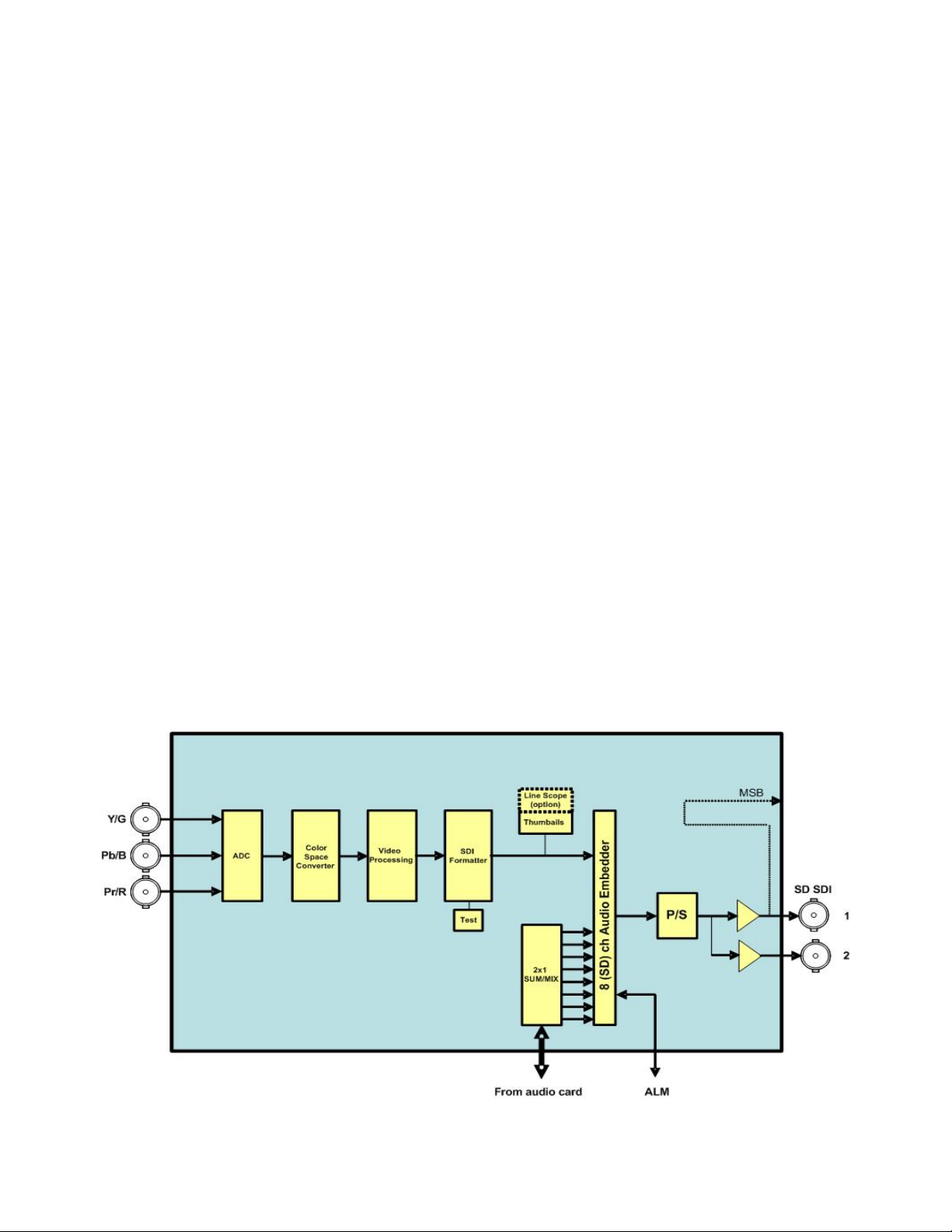
1.3 Block Diagram
ADC-1101 | 1
Page 6
GUIDE TO INSTALLATION AND OPERATION
A
A
r
1.4 Card Front Edge Layout
S
U
T
T
S
Status Led
ADC-1101
SW1
T
C
E
1
L
D
E
S
BUS connecto
Select
Button
2 | ADC-1101
Page 7
GUIDE TO INSTALLATION AND OPERATION
2 Installation
2.1 Unpacking
The following items should be included in the ADC-1101 package:
• ADC-1101 CAV-to-SDI Converter
• ADC-1101-SRP rear panel
• User manual
2.2 Installation in the Densité frame
The ADC-1101 must be mounted in a DENSITÉ frame. The installation includes both the ADC-1101
module, and the rear panel module. It is not necessary to switch off the frame’s power when installing or
removing the card.
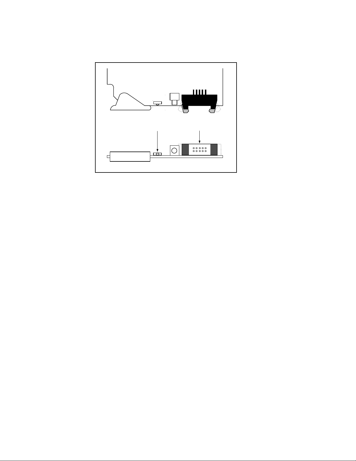
When the ADC-1101 is used in conjunction with an audio module such as the UAP-1783, the ABUS flat
cable must be installed between the ABUS connectors located on the front card edges (see section 1.4).
• Note: for a two card installation, use the two end connectors of the flat cable and leave the
middle one unplugged.
Detailed instructions for installing cards and their associated rear panels in the Densité frame are given in
the Densité Frame manual.
2.3 Connection
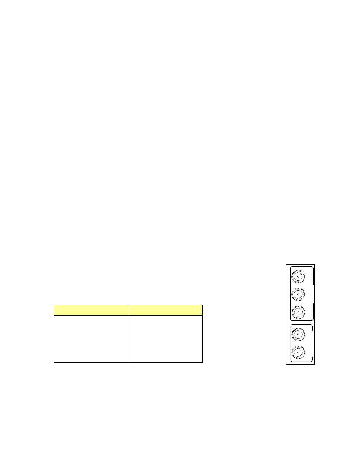
All video connections are made on the rear panel:
• Connect the CAV inputs to the three BNC connectors marked CAV IN
• Two SDI outputs are available on BNC connectors.
Component analog input formats supported by the ADC-1101:
525 formats 625 formats
G/Y
B/B-Y
R/R-Y
CAV IN
GBR without setup GBR
GBR with setup EBU
1
SDI OUT
SMPTE Beta
Beta without setup
2
Beta with setup
ADC-1101-SRP
ADC-1101 | 3
Page 8
GUIDE TO INSTALLATION AND OPERATION
3 Operation
3.1 Control Options
The ADC-1101 has two primary control interfaces:
• The local control panel attached to the Densité frame’s controller
• Remote control using Miranda’s iControl system
These will be explained in detail in the following sections.
3.2 Local control using the Densité frame control panel
Push the SELECT button on ADC-1101 card edge (see Section 1.4) to assign the local control panel to
operate the ADC-1101. Use the control panel buttons to navigate through the menu, as described below.
All of the cards installed in a Densité frame are connected to the frame’s controller card, which handl es all
interaction between the cards and the outside world. There are no operating controls located on the cards
themselves. The controller supports remote operation via its Ethernet ports, and local operation using its
integrated control panel.
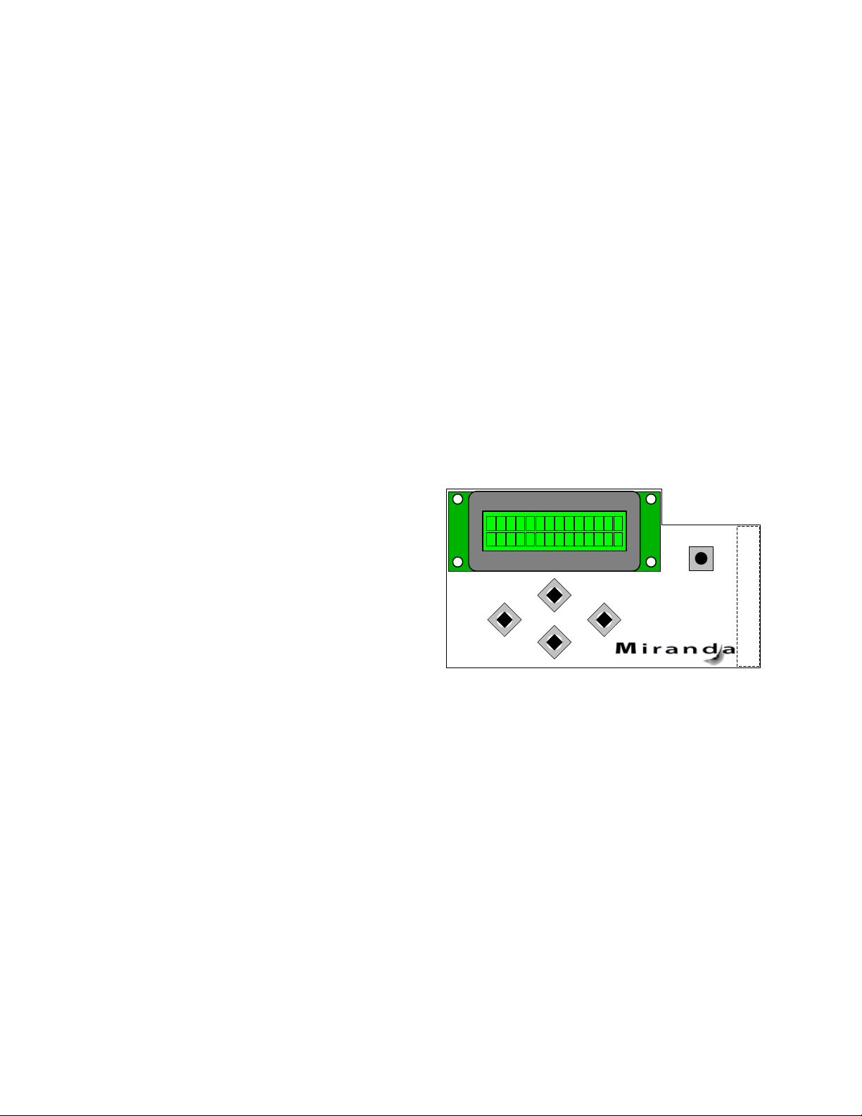
The local control panel is fastened to the controller
card by a hinged connector, and when installed is
located in the front center of the frame, positioned in
front of the power supplies. The panel consists of a
display unit capable of displaying two lines of text,
each 16 characters in length, and five pushbuttons.
The panel is assigned to operate any card in the frame
by pushing the SELECT button on the front edge of
that card. Pushing the CONTROLLER button on the
control panel selects the Controller card itself. The
STATUS LED on the selected card flashes yellow.
The local control panel displays a menu that can be navigated using the four pushbuttons located beneath
the display. The functionality of the pushbuttons is as follows:
[CTRL] Selects the controller card for status monitoring and adjustment
[+] [–] Used for menu navigation and value modification
[SELECT] Gives access to the next menu level. When a parameter value is shown, pu shing this button
once enables modification of the value using the [+] and [–] buttons; a second push confirms the
new value
[ESC] Cancels the effect of parameter value changes that have not been confirmed; pushing [ESC]
causes the parameter to revert to its former value.
Pushing [ESC] moves the user back up to the previous menu level. At the main menu, [ESC]
does not exit the menu system. To exit, re-push the [SELECT] button for the card being
controlled.
If no controls are operated for 30 seconds, the controller reverts to its normal standby status, and the
selected card’s STATUS LED reverts to its normal operating mode.
ESC
+
-
CONTROLLER
SELECT
4 | ADC-1101
Page 9
GUIDE TO INSTALLATION AND OPERATION
3.2.1 Status LED
The status monitor LED is located on the front card-edge of the ADC-1101, and is visible through the front
access door of the DENSITÉ frame. This multi-color LED indicates module status by color, a nd by
flashing/steady illumination, according to the chart. The chart also indicates fault reporting for this card on the
DENSITÉ frame’s serial and GPI interfaces.
Serial
Report
GPI
Report
Green Yellow Red
Flashing
Red
No input signal presence
Input Format Error
Test
Card System
: Factory default.
NOTE: A “Flashing Yellow” Status LED indicates that the SELECT button on the front panel has been
pushed.
3.2.2 Menu for local control
The ADC-1101 has operating parameters which may be adjusted locally at the controller card interface. After
pressing the SELECT button on the ADC-1101 module, use the keys on the local control panel (described
above) to step through the displayed menu and adjust the parameters. The menu is shown below.
STATUS NO SIGNAL / 525 / 625
NO REAR / SINGLE REAR
TEST ON
A1 MISSING
A2 MISSING
HARDWARE FAILURE
INPUT FORMAT
[SMPTE
[EBU
CC [OFF
WSS [OFF
AUTO CALIBRATE START O.K / NO GOOD
USER PRESET LOAD [USER 1 ,USER 2, USER 3, USER 4, USER 5]
SAVE [USER 1 ,USER 2, USER 3, USER 4, USER 5]
/ GBR / GBR w. setup / BETA / BETA w. setup]
/ GBR / BETA] (625)
, ON]
, ON] (625)
(525)
(525)
ADC-1101 | 5
Page 10

GUIDE TO INSTALLATION AND OPERATION
VIDEO PROC Y OFFSET [-100mV, -99.2mV, …0
B-Y OFFSET [-100mV, -99.2mV, …0
R-Y OFFSET [-100mV, -99.2mV, …0
Y GAIN [-800, -799,…0
B-Y GAIN [-800, -799,…0
R-Y GAIN [-800, -799,…0
CORING [OFF
AUDIO EMBEDDING CHANNELS 1234 TO [OFF
* Available with Audio
Card connected
CHANNEL 2 OPERATION MODE [OFF, A
ABUS [A1
CHANNEL SELECT [1, 2
LEVEL [-96, -95, …. 0]
MUTE [OFF
CHANNEL 3 OPERATION MODE [OFF, A, SUM(A+B
SOURCE A ABUS [A1
CHANNEL SELECT [1, 2, 3
SOURCE B ABUS [A1
CHANNEL SELECT [1
SUM (A+B) LEVEL -6, -3
MUTE [OFF
CHANNEL 8 OPERATION MODE [OFF, A, SUM(A+B), MIX
SOURCE A ABUS [A1
CHANNEL SELECT [1, 2, 3, …. 16]
LEVEL [-96, -95, …. 0]
SOURCE B ABUS [A1
CHANNEL SELECT [1
LEVEL [-96, -95, …. 0]
MUTE [OFF
WORD LENGTH [20 bits
CHANNELS 5678 TO [OFF
OUTPUT
MIXERS
, ON]
CHANNEL 1 OPERATION MODE [OFF
, 24 bits]
…99.2mV, 100mV]
…99.2mV, 100mV]
…99.2mV, 100mV]
, …. 799, 800]
, …. 799, 800]
, …. 799, 800]
, GRP 1, GRP 2, GRP 3, GRP 4]
, GRP 1, GRP 2, GRP 3, GRP 4]
, A, SUM(A+B), MIX]
, SUM(A+B), MIX]
, A2]
, 3, …. 16]
(dB)
/ ON]
), MIX]
, 0 dB
/ ON]
/ ON]
, A2]
, …. 16]
, A2]
, 2, 3, …. 16]
]
, A2]
(dB)
, A2]
, 2, 3, …. 16]
(dB)
6 | ADC-1101
Page 11

GUIDE TO INSTALLATION AND OPERATION
BLANKING VBI (10-20) [PASS, BLANK, PROCESS, USER]
VBI (6-22) [PASS
INPUT ERROR [KILL
CARD SYSTEM [NONE
TEST VIDEO [OFF
AUDIO CH 1&2 [OFF
AUDIO CH 3&4 [OFF
AUDIO CH 5&6 [OFF
AUDIO CH 7&8 [OFF
CONFIG ALARMS NO SIGNAL ALARM LEVEL [GREEN, YELLOW, RED
ALARM REPORT [NONE
TEST ALARM LEVEL [GREEN, YELLOW
ALARM REPORT [NONE
CARD SYSTEM ALARM LEVEL [GREEN, YELLOW, RED
ALARM REPORT [NONE
VERSION ADC-1101: xxx
OPTIONS LINE SCOPE ON/OFF Key: xx.xx.xx.xx
FACTORY DEFAULT [RESTORE]
, PASS]
, A1, A1 + A2]
, BLANK, PROCESS, USER]
/ ON]
/ ON] * Available with Audio Card connected
/ ON] * Available with Audio Card connected
/ ON] * Available with Audio Card connected
/ ON] * Available with Audio Card connected
( 525 )
( 625 )
, GPI]
, RED, FLASH RED]
, GPI]
, GPI]
* USER available only with IControl
* USER available only with IControl
, FLASH RED]
, FLASH RED]
ADC-1101 | 7
Page 12

GUIDE TO INSTALLATION AND OPERATION
3.3 Remote control using iControl
The operation of the ADC-1101 may be controlled using Miranda’s iControl system.
• This manual describes the control panels associated with the ADC-1101 and their use.
• Please consult the iControl User’s Guide for information about setting up and operating iControl.
In iControl Navigator or iControl Websites, double-click on the ADC-1101 icon to open the control panel.
3.3.1 The iControl graphic interface window
The basic window structure for the ADC-1101 is shown in figure 3.1. The window identification line at the top
gives the card type (ADC-1101), and the slot number in which the card is installed in the Densité frame. On
the left is a Status icon for the card (see Section 3.3.12 for a discussion of status monitoring).
Figure 3.1 ADC-1101 iControl graphic interface window
There are four main sections in the window itself, identified in figure 3.1:
1. The top section displays icons on the left. These icons report different statuses such as card
communication status, input signal and reference signal format and statuses.
Move the cursor over an icon to see its current status in the message area below the icons. If there is
an error status, the message will appear automatically. If there are multiple error messages, the display
will cycle through them
8 | ADC-1101
Page 13

GUIDE TO INSTALLATION AND OPERATION
Icon # Indicates appearance interpretation
1 Card control
status
2 Input status
3 Audio/Video test
4 ABUS Multiple
Card
Configuration
2. The left portion of the window contains all the parameter groups, which become h ighlighted when they
are selected; the main panel (4) then displays the group’s set of parameters. Each of the groups is
described in detail below.
3. The lower section of the window contains controls to access the user presets.
4. The main panel contains all the parameters specific to the group selected. It may contain several tabs to
help manage the different parameters.
Green if the card is controlled remotely
Yellow when locally controlled
Green if OK,
Red if error detected
Green if test signal is OFF,
Yellow with type indicators when test signal is
enabled:
• Color bar for color bar test signal
• Loudspeaker for audio test signal
Green if OK,
Red if the detected card configuration does not
match the configuration set on the ABUS panel
3.3.2 The Input group
Use the radio buttons in this panel to set the
input video format for this card.
The available options are different for 525 and
625 operation:
525 input options
• SMPTE
• GBR
• GBR with SETUP
• BETA
• BETA with SETUP
625 input options:
• EBU
• GBR
• Beta
Figure 3.2 Input group
ADC-1101 | 9
Page 14

GUIDE TO INSTALLATION AND OPERATION
3.3.3 The Video Processing group
Use the controls on this panel to process the
incoming analog video before the A-to-D
conversion. The following controls are available:
Figure 3.3 Video Processing group
3.3.4 The Audio Output group
Each of these tabs controls the output processing
for two output channels – source selectors, level
controls and mixers for each output.
The Operation Mode pulldown establishes the
configuration of the controls for an output channel.
There are four options:
A (see CH 1 in figure 3.4)
The source is selected using the Source A
ABUS Select and Channel pulldowns, and its
level is adjusted using the slider or data box.
• The ABUS select options are:
o V select one of the 16 channels from
the video card.
o A1 select one of the 16 channels from
an audio card. A1 is always Local,
Slave 1 or Master
o A2 select one of the 16 channels from
an audio card. A2 is always
Slave2 or Slave. Figure 3.4 Audio Output group – CH 1&2 tab
• The output Level is adjustable from -96 to 0 dB with the slider or a direct keyboard entry.
10 | ADC-1101
Page 15

GUIDE TO INSTALLATION AND OPERATION
SUM (A+B) (see CH 2 in figure3.4)
Two sources are selected using the Source A and Source B ABUS Select and Channel pulldowns. The
two sources are added, and the level of the combined signal is attenuated by the amount selected in the
Sum (A+B) LEVEL pulldown.
• The ABUS select options are:
o V select one of the 16 channels from the video card.
o A1 select one of the 16 channels from an audio card. A1 is always Local, Slave 1 or Master
o A2 select one of the 16 channels from an audio card. A2 is always Slave2 or Slave.
• The Sum (A+B) Level pulldown offers attenuations of 0 dB, -3 dB and -6 dB.
NOTE: If you attempt to mix two different audio types to an output, only the Source A signal will be
routed to this output and the Source A audio type will be displayed. The Source B signal will be
ignored.
Mix (see CH 3 in figure 3.5)
Two sources are selected using the Source A
and Source B ABUS Select and Channel
pulldowns. The two sources are mixed, with
the level of each source adjusted using its
slider or data entry box.
• The ABUS select options are:
o V select one of the 16 channels
from the video card.
o A1 select one of the 16 channels
from an audio card. A1 is always
Local, Slave 1 or Master
o A2 select one of the 16 channels
from an audio card. A2 is always
Slave2 or Slave.
• The contribution of each of the sources to
the mix is adjusted using its Level slider
or direct keyboard entry into the data box,
over a range from -96 to 0 dB.
Figure 3.5 Audio Output group – CH 3&4 tab
NOTE: If you attempt to mix two different audio types to an output, only the Source A signal will be
routed to this output and the Source A audio type will be displayed. The Source B signal will be
ignored.
OFF (See CH 4 in figure 3.5)
The output is muted.
ADC-1101 | 11
Page 16

GUIDE TO INSTALLATION AND OPERATION
3.3.4.1 Audio Output – Embedding tab
CH1,2,3,4, and CH 5,6,7,8: the pulldown box
allows the user to choose the AES audio group
in which audio channels 1 to 4 and 5 to 8 will be
embedded
Figure 3.6 Audio Output group – Embedding tab
3.3.4.2 Audio Output - Config tab:
The Audio Embed pulldown box sets the bit
level of the embedded audio at the output:
• 20 bits or 24 bits
Figure 3.7 Audio Output group – Config tab
12 | ADC-1101
Page 17

GUIDE TO INSTALLATION AND OPERATION
F
3.3.5 The Thumbnail group
The thumbnail area displays a thumbnail image of
the video signal being processed by the ADC-
1101.
Player – turn the player function (i.e. display in
this panel) OFF or ON (Thumbnail)
Enable – set thumbnail generation to Video, Test
(test signal is generated, medium size only), or
OFF. Use Video mode for normal operation.
Size – choose the thumbnail size: small, medium,
large
Quality – choose the quality of the displayed
image by selecting Poor, Normal or HiQ from the
pulldown list
Rate – select the desired refresh rate from the
pull-down box. The choices are:
[Fast, 1 sec, 2 sec, …, 9 sec, 10 sec.]
Streaming Priority Control – Click the Take control
from Slot [##] checkbox to force the Densité
Controller for this frame to assign more bandwidth for this card’s streaming output. Only one card in the
frame can use this feature. It has no effect unless you have selected Fast for the refresh rate. The actual slot
number of this card, as shown in the window title bar, will appear when the checkbox is ticked.
• Note that this check box is not available if the Densité frame is equipped with an ETH2 controller card.
Figure 3.20 Thumbnail group
Figure 3.8 Thumbnail group
3.3.6 The RALM group
The Remote Audio Level Meter (RALM) panel
displays audio level meters for up to 8 channels.
• The source for each meter is configured in the
RALM Remote Control area at the bottom of the
control panel, and in the RALM Connections
tab.
Speed – select the meter response from the pull-down
list, options are [fast, medium, slow]
RALM Connections tab
igure 3.10 RALM group – RALM Connections tab
Figure 3.9 RALM group
ADC-1101 | 13
Page 18

GUIDE TO INSTALLATION AND OPERATION
Use the radio buttons to turn the meter display ON (RALM) or OFF for the indicated channels. The meter
appears directly above the controls.
Reset Counter: click this button to reset the overload counter on the ALM display to zero. See the next
section for instructions on setting up the overload counter.
Meter Ballistics Config tab
Figure 3.11 RALM group – Meter Ballistics Config tab
Type – select a type of meter from the pull-down list
Figure 3.12 Meters shown in Type pulldown
Upper Zone Limits – select the crossover level between the upper and middle zones of the meter (the range
of values shown in the pull-down list depends on the type of meter selected)
Lower Zone Limits – select the crossover level between the middle and lower zones of the meter (the range
of values shown in the pull-down list depends on the type of meter selected)
Color samples – the three samples show the current selected color for the upper, middle and lower zones of
the meter.
• Click on the color sample of a zone to open a color selection panel to choose a different color for that
zone
Overload Cursor – The overload cursor appears on the meter as an arrowhead in the meter scale. The two
pulldown boxes set the position of the overload cursor on the left and right meters. If the audio level on that
channel goes above the cursor, the Overload Counter at the top of the meter is incremented.
14 | ADC-1101
Page 19

GUIDE TO INSTALLATION AND OPERATION
Fig
3.3.7 The Blanking group
This panel allows the Vertical Blanking Interval
(VBI) processing to be specified. Options available
are:
• Process - Process any VBI information
present at the input with the same gain and
offset parameters used for the active video
(these are set in the video processing tab)
• Pass – Send any VBI information present at
the input to the output SDI signal without
modification
• Blank – Replace any information that may
have been present on a specific VBI line with
black.
Apply an option to the entire VBI by selecting the
option in the VBI box. If Line by Line is selected,
the option can be specified for each individual line,
in the Line By Line area.
Extended VBI:
The contents of this box depend on the input signal
line rate:
• 625 line: Click in the checkbox to include line 23 (WSS signal) in the VBI.
• 525 line: Click in the check box to include line 21 (closed captioning) in the VBI
Figure 3.13 Blanking group
3.3.8 The Test group
This panel inserts test signals at the output instead
of the incoming video and/or audio.
Video – click in the checkbox to insert color bars in
the output video
Audio – click in the checkbox to insert audio tones
in the indicated output audio channels
Note – the audio checkboxes will only be active if
there is an audio input signal
ure 3.14 Test group
ADC-1101 | 15
Page 20

GUIDE TO INSTALLATION AND OPERATION
3.3.9 The Options group
The IP Scope option adds Waveform Monitor and
Vectorscope over IP functions to the ADC-1101,
using data generated by a line scope embedded
in the ADC-1101.
• To activate this option, you must obtain a
licence key from Miranda Technologies Inc.
• Type the licence key in the Enter Key box
and then click on Enable Option to enable
the option’s features
Once the Key has been entered, and the IP
Scope is activated, the controls on this panel can
be used to set its operating parameters
• Enable – Click in the checkbox to turn the
IP Scope ON
• Line – Use the slider to select the video line
that will be displayed by the Line Scope
• Refresh Rate – Use the pulldown to select
how often the display will be refreshed..
Figure 3.15 Options group
3.3.10 The ABUS group
When companion audio cards such as the UAP1781 and UAP-1783 are used to provide additional
audio channels, the ABUS audio bus links the
installed audio cards and the ADC-1101. This
panel, called ABUS group, is used to instruct the
ADC-1101 about the presence of installed audio
cards and the system configuration.
Multiple Card Config
A1/A2 Presence: Monitors the presence of
companion audio cards installed in the chassis
(see section 2.2 ADC-1101 Installation).
Card System Config: To enable the audio bus, use
the pull-down box and select your system’s
configuration. Selecting Video restricts available
audio signals to audio channels embedded in the
input signal; Video / A1 or Video / A1 / A2 adds the
audio channels incoming from the installed audio
cards that have been detected.
Figure 3.16 ABUS group
16 | ADC-1101
Page 21

3.3.11 The Factory group
Load Factory: Clicking this button will reset all
ADC-1101 parameters to factory-default values.
• The user presets are not affected by the
Load Factory command
Auto-Calibration (Color Bars): Click the Start
button to calibrate the card automatically using the
input signal.
• The input signal used to calibrate the card
MUST be a full field 100% color bar.
GUIDE TO INSTALLATION AND OPERATION
Figure 3.17 Factory group
3.3.12 The Alarm Config group
This panel allows the alarm reporting of the
ADC-1101 to be configured. The panel
opens in a new window when the button is
clicked, and can be resized if needed.
The panel is organized in columns.
Status/Name
This contains an expandable tree listing all
the alarms reported by this ADC-1101 card.
• Each alarm name includes an icon
that shows its current status
• Some alarms are text-only (see Input
Format or ABUS in fig. 3.18) and the
alarm status is shown in the name and
not by a status icon
The Card LED, Overall alarm and GSM
contribution columns contain pulldown lists
that allow the level of contribution of each
individual alarm to the alarm named in the
column heading to be set.
Figure 3.18 Alarm Configuration panel
ADC-1101 | 17
Page 22

GUIDE TO INSTALLATION AND OPERATION
• Card LED
This column allows configuration of the contribution of selected individual alarms to the status LED located
on the front card edge. The Card LED status is shown at the bottom of the alarm tree in the Status.Name
column.
• Overall Alarm
This column allows configuration of the contribution of each individual alarm to the Overall Alarm
associated with this card. The Overall Alarm is shown in the upper left corner of the iControl panel, and
also appears at the bottom of the Status/Name column..
• GSM Contribution
This column allows configuration of the contribution of each individual alarm to the GSM Alarm Status
associated with this card. GSM is a dynamic register of all iControl system alarms, and is also an alarm
provider for external applications. The possible values for this contribution are related to the Overall alarm
contribution:
• If the Overall alarm contribution is selected as Disabled, the GSM alarm contrib ution ca n be set to any
available value
• If the Overall alarm contribution is selected as any level other than disabled, the GSM contribution is
forced to follow the Overall Alarm.
Levels associated with these alarms:
The pulldown lists may contain some or all of the following options:
The alarm makes no contribution (black icon)
The alarm is of minor importance (yellow icon)
The alarm is of major importance (orange icon)
The alarm is of critical importance (red icon)
The alarm exists but has no effect (used for text and composite alarms)
Shortcut: if you click in one of the columns beside a major heading in the Status/Name colu mn (where
there is no pulldown shown), you will open an “invisible” pulldown that lets you assign a level to all alarms
in that section of the column simultaneously.
Log Events
iControl maintains a log of alarm events associated with the card. The log is useful for troubleshooting and
identifying event sequences. Click in the checkbox to enable logging of alarm events for each individual
alarm.
At the bottom of the window are several other controls
Overall follow LED
Click in the checkbox to force the Overall alarm to be
identical to the Card LED status
• All Overall alarms for which there is a Card LED
alarm will be forced to match the Card LED alarm
• All Overall Alarms for which there is no Card LED
alarm will be forced to Disabled
A warning box will open allowing you to confirm the
action, since it will result in changes to the configuration
and there is no undo function.
Figure 3.19 Overall follow LED warning
18 | ADC-1101
Page 23

GUIDE TO INSTALLATION AND OPERATION
Copy to other cards
Click this button to open a panel that allows the alarm
configuration set for this card to be copied into another
ADC-1101 card.
• Select one or more destination cards from the
list in the window by clicking in the checkboxes,
or all of them by clicking in the All checkbox
• Note that when you do a Copy Profile for this
card (see Sect. 3.3.14), the alarm configuration
is copied along with all the other settings.
Figure 3.20 Copy to other cards
Get alarm keys
Click this button to open a save dialog where you can
save a file containing a list of all alarms on this card
and their current values, along with an Alarm Key for
each. The alarm keys are useful for system
integration and troubleshooting.
• The file is saved in Excel.csv format
Figure 3.21 Get alarm keys save dialogue
OK, Apply, Cancel
• OK accepts the settings and closes the window once the card confirms that there are no errors.
• Apply accepts the settings, but leaves the window open
• Cancel closes the window without applying any changes, and leaves the previous settings intact.
ADC-1101 | 19
Page 24

GUIDE TO INSTALLATION AND OPERATION
3.3.13 The Info group
When the ADC-1101 is included in an iControl
environment, certain information about the card
should be available to the iControl system. The
user can enter labels and comments that will make
this card easy to identify in a complex setup. This
information is entered into data boxes in the Info
control panel.
Label: type the label that appear for this
ADC-1101 when it appears in
iControl applications
Short Label type the short-form label that
iControl uses in some cases (8
characters)
Source ID type a descriptive name for this
ADC-1101
Comments: type any desired text
The remaining data boxes show manufacturing
information about this card.
Figure 3.22 Info group
Three buttons in the panel give access to other information.
• Details…: Reports the Firmware version, service
version, and panel version for this card
• Advanced…: Shows the Miranda LongID for this card.
The Miranda LongID is the address of this ADC-1101in
the iControl network.
Figure 3.23 Details window
Figure 3.24 Advanced window
20 | ADC-1101
Page 25

• Remote System Administration – opens the Joining Locators
data box.
3.3.14 User Presets
The User Preset controls are located at the lower
left corner of the iControl panel. If they are not
visible, click the arrow icon on the left side to
reveal the buttons and presets.
Select any one of the five presets using the
pulldown list. The name of the currently-selected
User Preset is shown on the pulldown icon (e.g.
User1, User2,… User5)
• Click Load to load the contents of the
selected User Preset into the ADC-1101.
All parameter settings and values will be
replaced by the contents of the selected
User Preset.
• Click Save to store the current parameter
settings and values from the ADC-1101
into the selected User Preset. The existing
contents of the preset will be overwritten.
Figure 3.26 User Presets and Profiles
GUIDE TO INSTALLATION AND OPERATION
Figure 3.25 Joining Locators window
ADC-1101 | 21
Page 26

GUIDE TO INSTALLATION AND OPERATION
3.3.15 Profiles
A profile is a set of values representing the current configuration of the card. The profile can be saved to
disk and recalled from disk. It can also be copied from this ADC-1101 to another ADC-1101. Access these
operations by clicking on the Profiles button at the bottom left of the control panel (see figure 3.26)
Figure 3.27 Profile Copy window
22 | ADC-1101
Page 27

GUIDE TO INSTALLATION AND OPERATION
4 Specifications
ANALOG VIDEO INPUT
STANDARD YPbPr or RGB with sync
SMPTE/EBU, Betacam
CONNECTOR 3x BNC per IEC 60169-8 Amendment 2
IMPEDANCE 75 OHM
SIGNAL LEVEL 0.7V p-p or 1V p-p with sync
RETURN LOSS > 35dB up to 5.75 MHz
SERIAL DIGITAL OUTPUT
STANDARD SMPTE-259M, (270Mbps)
NUMBER OF OUTPUTS 2
CONNECTOR 2x BNC per IEC 60169-8 Amendment 2
SIGNAL LEVEL 800mV nominal
RETURN LOSS ADC-1101: >15dB up to 270MHz
JITTER <0.2 UI (WIDEBAND)
PROCESSING
QUANTIZATION 12-bit
SAMPLING 27 MHz (2x oversampling for luma)
(4x oversampling for chroma)
FREQUENCY RESPONSE +/- 0.1dB up to 5.5 MHz (Y)
<+/- 0.1dB up to 2.75 MHz (Cr, Cb)
GAIN (3 Components) +-/ 3dB
BLACK LEVEL +/- 100mV
PROCESSING DELAY 10 μsec
TEST SIGNAL
VIDEO 75% color bar with 100% white bar
AUDIO 1 kHz tone (R: continuo us, L: pulsed)
OTHER
MAXIMUM POWER 5W
PHYSICAL FORMAT Densité
ADC-1101 | 23
 Loading...