

Page 1
SERIE DENSITE
ADA-1033
ADA-1033 Single/ Dual Analogue Audio Distribution with remote gain
Guide to Installation and Operation
M479-9600-100
July 2004
Introduction
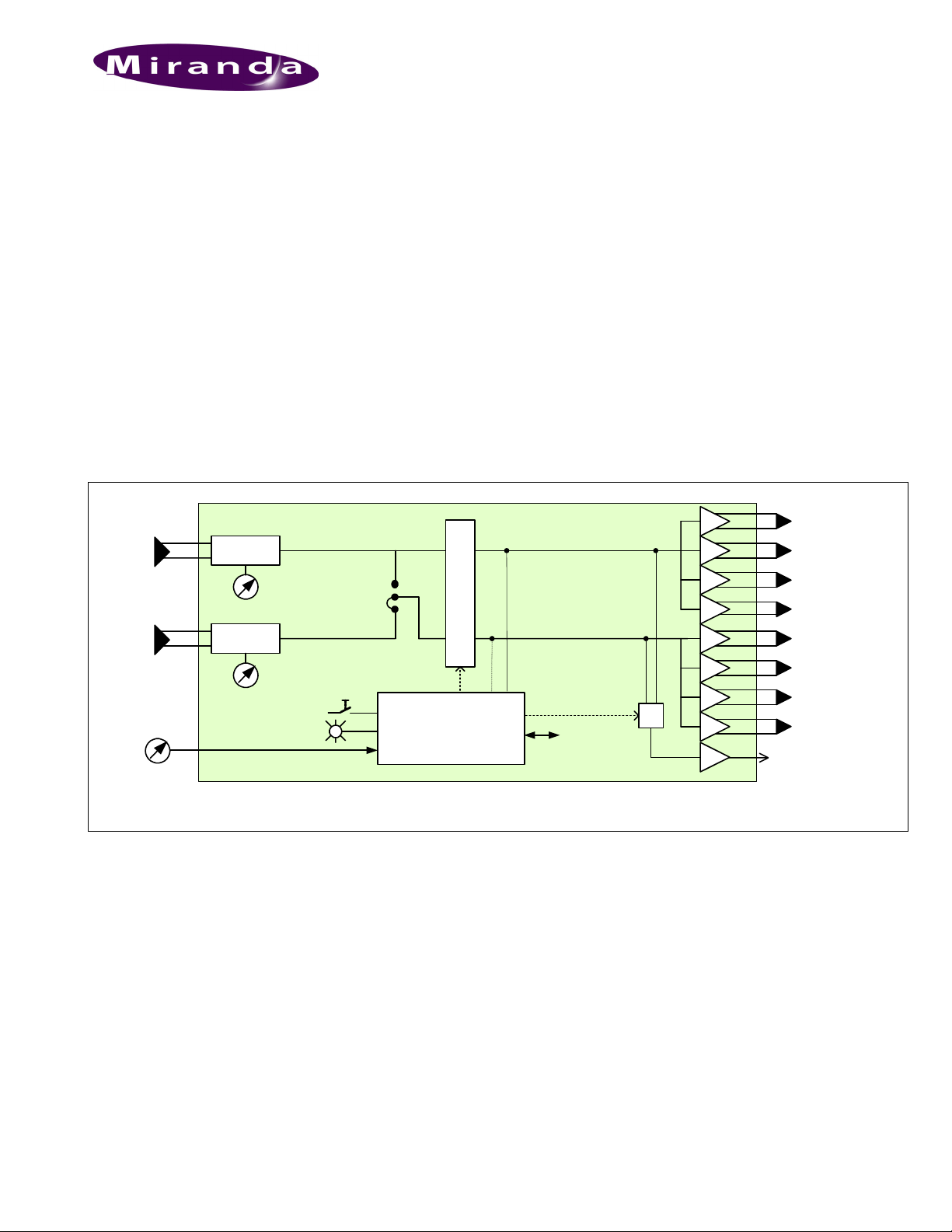
L’ADA-1033 is an analogue audio distribution amplifier that
can be configured for monaural or stereo applications. In
single mode, it distributes one input to eight outputs and in
dual mode each channel has four outputs.
Each channel gain is trim controlled from the frame controller
or from an external remote potentiometer. All modules of the
DENSITE Series include a push button on the card front
edge, which permits to assign the front panel controller to
consultation and adjustments. A multi-coloured Led, visible
with the door closed, reports the card status
The ADA-1033 requires a 'single' or a ‘double' rear connector
panel.
1
Amp
AUDIO
INPUTS
2
Remote
Gain
Control
Amp
Select
Status
Microcontroller
Features
• Balanced input and outputs
• Distribution amplifier 1 input / 8 outputs or 2 x 1 input / 4
outputs
• Remote control of gain by external potentiometer or from
front panel controller
• Intra frame output for monitoring
• Status LED and remote reporting
• Alarm configuration: absence signal, overload
• Easy to install audio connectors
1
2
3
4
Volume CTRL
Rem Control
5
6
7
8
To MONITOR
AUDIO
OUTPUTS
ADA-1033 Functional Block Diagram
Specifications
Input
Balanced
Signal: ...................... analogue audio
Impedance: .............. > 20 k Ω
Common mode
rejection: .................. > 50 dB
Outputs
Balanced
Signal : .................... balanced analogue audio
Impedance: .............. < 50 Ω
Specifications are subject to change without notice.
Processing performance:
Gain: .........................-96 to +31.5 dB (0.5 dB step)
Max. Level:................+25 dBu
SNR: .........................< -90 dBu
..................................20 Hz to 20 kHz unweighted
Distortion: .................< -85 dB (20 Hz to 20 kHz) @ +23 dBu
Cross talk : ...............<-100 dB (20 kHz)
Freq. response: ........±0.2 dB (20 Hz to 20 kHz)
Miscellaneous
Power:.......................single 4 W
..................................double 7.5 W
Page 2
ADA-1033
Guide to Installation and Operation
Menu Introduction
Most parameters are accessed and changed via an easy-to-use menu. The flow chart below outlines the entire ADA-1033
menu path. Each menu is described throughout this section.
The procedure and the operation mode are described in the common paragraph of the DENSITÉ Manual. The menu
organisation is made out of a main menu and several sub-menus. A press on the [SELECT] front panel push button accesses to
the menu. A lack of activity turns off the display. Default values are written with bold characters.
STATUS
NO SIGNAL DELAY
SIGNAL THRESHOLD -48, -42, -36, -30, -24 [dBu]
OVERLOAD THRESHOLD -9, ..., +24 [dBu]
LEVEL LEVEL 1 -96, ..., 0, ..., +31.5 [dB]
LEVEL 2 -96, ..., 0, ..., +31.5 [dB]
LEVEL 1&2 -96, ..., 0, ..., +31.5 [dB]
MONITORING OUT 1, OUT 2, OUT 1&2
CONFIGURE ALARM
OVERLOAD 1 ALARM LEVEL
OVERLOAD 2
NO SIGNAL 1
NO SIGNAL 2
REAR PANEL ERROR, OVERLOAD 1, OVERLOAD 2, OVERLOAD 1&2,
NO SIGNAL 1, NO SIGNAL 2, NO SIGNAL 1&2, ALL OK
SINGLE, DUAL
0, ..., 15, ..., 255 [sec]
GREEN, YELLOW, RED, FLASH RED
ALARM REPORT
ALARM LEVEL
ALARM REPORT
ALARM LEVEL
ALARM REPORT
ALARM LEVEL GREEN, YELLOW, RED, FLASH RED
ALARM REPORT
NONE, GPI
GREEN, YELLOW, RED, FLASH RED
NONE, GPI
GREEN, YELLOW, RED, FLASH RED
NONE, GPI
NONE, GPI
FACTORY DEFAULT
RESTORE
Menu Description
{STATUS}
Displays status of the different board alarms. The higher-level
alarm is displayed, even if not configured to activate the
STATUS Led. ALL OK indicates an absence of alarm.
REAR PANEL ERROR Indicates an absence of the rear
panel or an incompatibility between
the module and the rear panel. The
STATUS led turns on flashing red.
OVERLOAD Indicates an internal signal level
higher than the selected threshold.
NO SIGNAL Indicates an internal signal level lower
than the selected threshold during a
user defined period.
MODE SINGLE/DUAL Displays the module configuration.
{NO SIGNAL DELAY}
Signal absence is declared when the level signal is lower than
the signal threshold during the selected period, it can be
adjusted from 0 to 255 s. The default value is set to
15 s.
{SIGNAL THRESHOLD}
The presence signal threshold can be adjusted from – 48 to
– 24 dBu by 6 dBu steps. The default value is
– 36 dBu.
{OVERLOAD THRESHOLD}
The overload signal threshold can be set from –9 to +24 dBu.
The default value is +24 dB.
Page 3

ADA-1033
Guide to Installation and Operation
{LEVEL}
Permits the adjustment of the level of channel 1 or 2
separately or simultaneously.
LEVEL Signal gain can be set from –96 to
+31.5 dB. The default value is 0 dB.
{MONITORING}
Allows the pre-selection of the monitored signal. The
ON/OFF command will come from a monitor module like the
MSB-1121 in slot 20 of the Densité frame.
{CONFIGURE ALARM}
It is possible to associate the STATUS Led colour and/or a
GPI relay activation to each detected error.
Alarm relay activation depends of the ENABLE selection of
the controller board menu GPI REPORT.
ALARM LEVEL Associates to each error the STATUS
led colour: GREEN, YELLOW, RED
and FLASH RED. This selection has
no influence on the {STATUS} menu
display.
ALARM REPORT The default value NONE is assigned
to errors. Alarm relay activation will
be associated to an error when GPI is
set.
{FACTORY DEFAUT}
RESTORE Set the module with the factory default
parameters.
Status and Report
This table shows the front Led colour and the report action according to the level of a given error condition. Notice that the
“Flashing Yellow” indicates that the SELECT button on the front panel has been pushed, and the card is being accessed via
the communication protocol.
Overload on Input 1
Overload on Input 2
No signal detected on Input 1
No signal detected on Input 2
Card accessed via the communication protocol
Rear Panel not matching
: Factory default.
Note: The non requested message affectation to an alarm status can only be accessed by the communication protocol (serial
port)
Non
requested
- - - - - - Yes
- - - - - Yes -
GPI
Report
Green Yellow Red
Flashing
Red
Flashing
Yellow.
-
-
-
-
Page 4

ADA-1033
Guide to Installation and Operation
Front Edge Presentation Board Presentation
PT1
SW1
D1
GAIN 1
STATUS
SELECT
PT2
GAIN 2
Status Indicator
Gain Adjust.
Push Button
Gain Adjust.
ADA-1033
Configuration
PT1
1 GAIN
PT2
2 GAIN
JP 1 JP 1 sets the operating mode Single = 1 x 8 or
GAIN adjustment
Trimmer for fine adjustment of the gain within
an 2.5 dB range
Dual = 2 (1 x 4)
Connections
ADA-1033 is used with the single rear panel ADA-1033-SRP
that includes 1 input to 4 outputs or with the double rear panel
ADA-1033-DRP that includes 1 input to 8 outputs (single
mode) and 2 x 1 input to 4 outputs (dual mode).
ADA-1033-DRP ADA-1033-SRP
High
GND
Low
+31.5
Pot 10k
LIN
3
2
1
3
2
1
-96
AUDIO IN
12
1
AUDIO OUT
2
3
4
REM-GAIN
5
6
7
8
REM-GAIN
AUDIO IN
AUDIO OUT
ADA-1033
IN
1
2
3
4
REM-GAIN
AUDIO
AUDIO OUT
ADA-1033
No need to terminate REM-GAIN connector when not used.
 Loading...