

Page 1
ADA-1023 Single/Dual Analog Audio Distribution Amplifier
(DENSITÉ) SERIES
ADA-1023
Description
The ADA-1023 is an analog audio DA that can be
configured for single or dual channel (stereo)
operation. In single channel mode, 8 outputs can
be driven while in dual channel mode, each
channel has four outputs. A wide range of level
gain control is possible and controlled from the
card edge. A signal status is also available
indicating the presence of the input signal(s).
The ADA-1023 requires a ‘double' rear connector
panel.
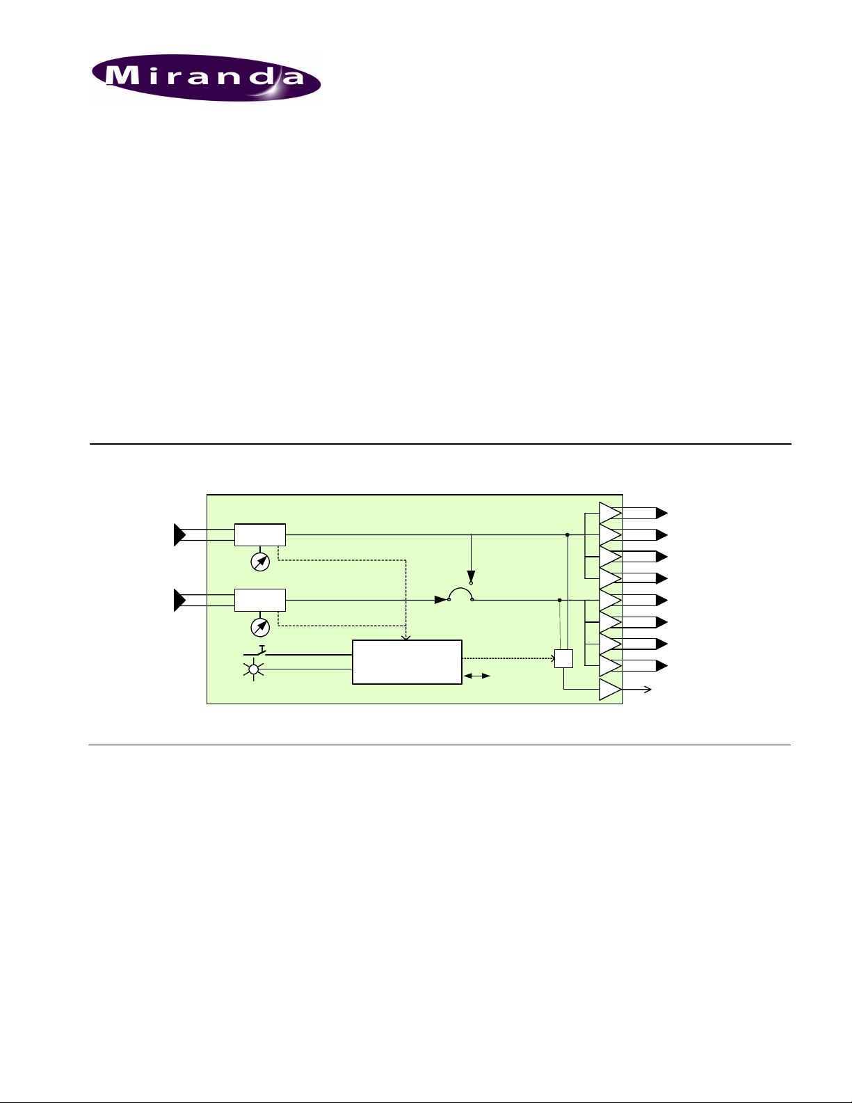
FUNCTIONAL BLOCK DIAGRAM
AUDIO
Inputs
1
2
Amp
Amp
Select
Status
Features
• Single or dual analog audio input(s)
• Single channel 8-output or dual channel
(stereo) 4-output
• Balanced inputs and outputs
• Wide control of gain (-8 to +32 dB)
• Status LED and remote reporting of
presence and overload.
• Provides output to Monitoring Switching
Bridge option (MSB-1121)
Microcontroller
Rem Control
Guide to Installation and Operation
M451-9600-101
March 2008
1
2
3
4
AUDIO
Outputs
5
6
7
8
To Monitor
ADA-1023 Block Diagramm
SPECIFICATIONS
Input
Balanced
Signal: .......................analog audio
Impedance: ..............> 20 k Ω
Common mode
rejection: ..................> 50 dB
Output
Balanced
Signal: ......................balanced analog audio
Impedance: ..............< 50 Ω
Processing performance
Gain: ........................ -8 to +32 dB
Max. Level: ...............+25 dBu
SNR: ........................ < -95 dBu
20 Hz to 20 kHz unweighted
Distortion: ................ < -85 dB (20 Hz to 20 kHz) @ +23
dBu
Freq. response: ........ ±0.2 dB (20 Hz to 20 kHz)
Crosstalk:.................. 100 dB
Miscellaneous
Overload threshold: . +9 to +24 dBu (1 dB steps)
Signal absence:
-Fixed threshold: ..... -48 to -24 dBu (6 dB steps)
-Adjust. Delay: ........from 0 to 255 s
Power: ...................... 7 W
ADA-1023 Page 1 of 4
Page 2
ADA-1023 Single/Dual Analog Audio Distribution Amplifier
Guide to Installation and Operation
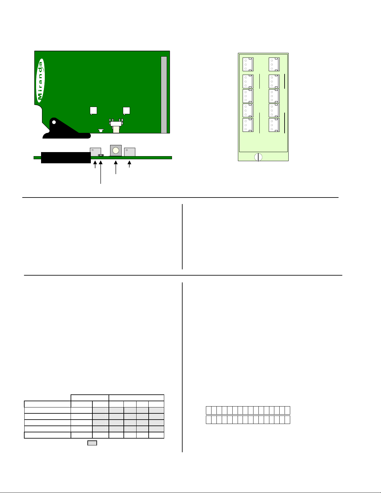
1
GAIN
ADA-1023
Gain 1 Adj.
Status LED
INSTALLATION
Make sure the following items have been shipped with your
ADA-1023. If any of the following items are missing, contact
your distributor or Miranda Technologies Inc.
* ADA-1023 Analog Audio Distribution Amplifier
* ADA-1023-DRP rear connector panel
The ADA-1023 and its associated rear connector panel must be
mounted in a DENSITÉ frame. It is not necessary to switch off
OPERATION
Overview
The DENSITÉ frame incorporates a central controller card,
located in the center of the frame, which is equipped with an
LCD display and a control panel. The controller handles error
reporting and local and remote control for all cards installed in
the frame. The display and control panel are assigned to the card
in the frame whose SELECT button has been pushed.
Status Monitor LED
The status monitor LED is located on the front card-edge of the
ADA-1023 module, and is visible through the front access door
of the DENSITÉ frame. This multi-color LED indicates module
status by color, and by flashing/steady illumination, according to
the following chart (which also indicates fault reporting for this
card on the DENSITÉ frame’s serial and GPI interfaces).
REPORT COLOR (F=flashing)
SERIAL GPI G Y R FR
Overload input 1
Overload input 2
No signal input 1
No signal input 2
No rear panel
: Factory default. User configurable
SDA-1101 - SD DIGITAL VIDEO DISTRIBUTION AMPLIFIER
2
GAIN
STATUS
SELECT
Gain 2 Adj.
SELECT button
ADA-1023 Rear Connector Panel
the frame’s power when installing or removing the ADA-1023.
Detailed instructions for installing cards and their associated rear
panels are given in the Densité Frame manual.
When used with a ADA-1023-DRP, the module must be installed
in the right-most of the two slots covered by the rear panel in
order to mate with the panel’s connectors. If it is placed in the
wrong slot, the card’s STATUS LED will flash red. Move the
card to other slot for correct operation. No damage will result to
the card should this occur.
A “Flashing Yellow” Status LED indicates that the SELECT
button on the front panel has been pushed, and the controller
display and control panel are now assigned to this card.
The LED color assignments for some error conditions can be
reconfigured by the user (see the chart and menu for details).
User Interface
Pushing the SELECT button will cause the on-card STATUS
LED to flash yellow, and the card identification and the current
status will be shown on the controller card’s display. The
STATUS LED will revert to its normal state upon a second push
of the button, or after a short delay. The messages which may
appear are shown in the top line of the menu chart on page 3
Example:
A D A - 1 0 2 3
Use the local control panel to access the detailed status report
shown in the STATUS menu below.
ADA-1023-DRP
AUDIO IN
1
+ G -
1
+ G - + G -+ G - + G -
2
AUDIO OUT
3
4
A L 2N O S I G N
2
5
+ G - + G -+ G - + G -+ G -
6
7
8
AUDIO IN
AUDIO OUT
ADA-1023
Page 2 of 4 ADA-1023
Page 3
ADA-1023 Single/Dual Analog Audio Distribution Amplifier
Operating Parameter Adjustment
The ADA-1023 has operating parameters which may be adjusted
at the controller card interface. After pressing the SELECT
button on the ADA-1023 card, use the keys on the local control
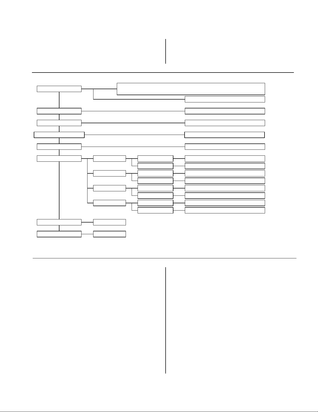
STATUS
REAR PANEL ERROR, OVERLOAD 1, OVERLOAD 2, OVERLOAD 1&2,
NO SIGNAL 1, NO SIGNAL 2, NO SIGNAL 1&2, ALL OK
Guide to Installation and Operation
panel (described in the Controller card manual) to step through
the displayed menu and adjust the parameters. The menus are
shown below.
SINGLE, DUAL
NO SIGNAL DELAY
SIGNAL THRESHOLD -48, -42, -36, -30, -24 [dBu]
OVERLOAD THRESHOLD -9, ..., +24 [dBu]
MONITORING OUT 1, OUT 2, OUT 1&2
CONFIGURE ALARM
VERSION
FACTORY DEFAULT RESTORE
OVERLOAD 1 ALARM LEVEL
ALARM REPORT
OVERLOAD 2
NO SIGNAL 1
NO SIGNAL 2
UC Vxxx
ALARM LEVEL
ALARM REPORT
ALARM LEVEL
ALARM REPORT
ALARM LEVEL GREEN, YELLOW, RED, FLASH RED
ALARM REPORT
OPERATION (continued)
STATUS menu
Displays status of the different board alarms. The higher-level
alarm is displayed, even if not configured to activate the
STATUS LED. ALL OK indicates an absence of alarms.
REAR PANEL ERROR
Absence of the rear panel or an
incompatibility between the module and the rear panel. The
STATUS led turns on flashing red
0, ..., 15, ..., 255 [sec]
GREEN, YELLOW, RED, FLASH RED
NONE, GPI
GREEN, YELLOW, RED, FLASH RED
NONE, GPI
GREEN, YELLOW, RED, FLASH RED
NONE, GPI
NONE, GPI
NO SIGNAL DELAY menu
Signal absence is declared when the level signal is lower than
the signal threshold during the selected period, which can be
adjusted from 0 to 255 s. The default value is set to 15 s.
SIGNAL THRESHOLD menu
The presence signal threshold can be adjusted from -48 to -24
dBu by 6 dBu steps. The default value is -36 dBu S.
OVERLOAD THRESHOLD menu
The overload signal threshold can be set from –9 to +24
OVERLOAD Indicates an internal signal level higher than
dBu. The default value is +24 dBu.
the overload threshold (channel indicated 1, 2, 1&2).
MONITORING menu
NO SIGNAL Indicates an internal signal level lower than the
signal threshold during a user defined period (channel
indicated 1, 2, 1&2).
Allows the pre-selection of the monitored signal. The
ON/OFF command will come from a monitor module like
the MSB-1121 in slot 20 of the Densité frame.
ADA-1023 Page 3 of 4
Page 4
ADA-1023 Single/Dual Analog Audio Distribution Amplifier
Guide to Installation and Operation
CONFIGURE ALARM menu
It is possible to associate a STATUS LED colour and/or a GPI
relay activation with each detected error. Alarm relay
activation occurs when the controller board menu item GPI
REPORT is set to ENABLE.
ALARM LEVEL: Associates a STATUS LED colour
(GREEN, YELLOW, RED or FLASH RED) with each error.
This selection has no influence on the {STATUS} menu
display.
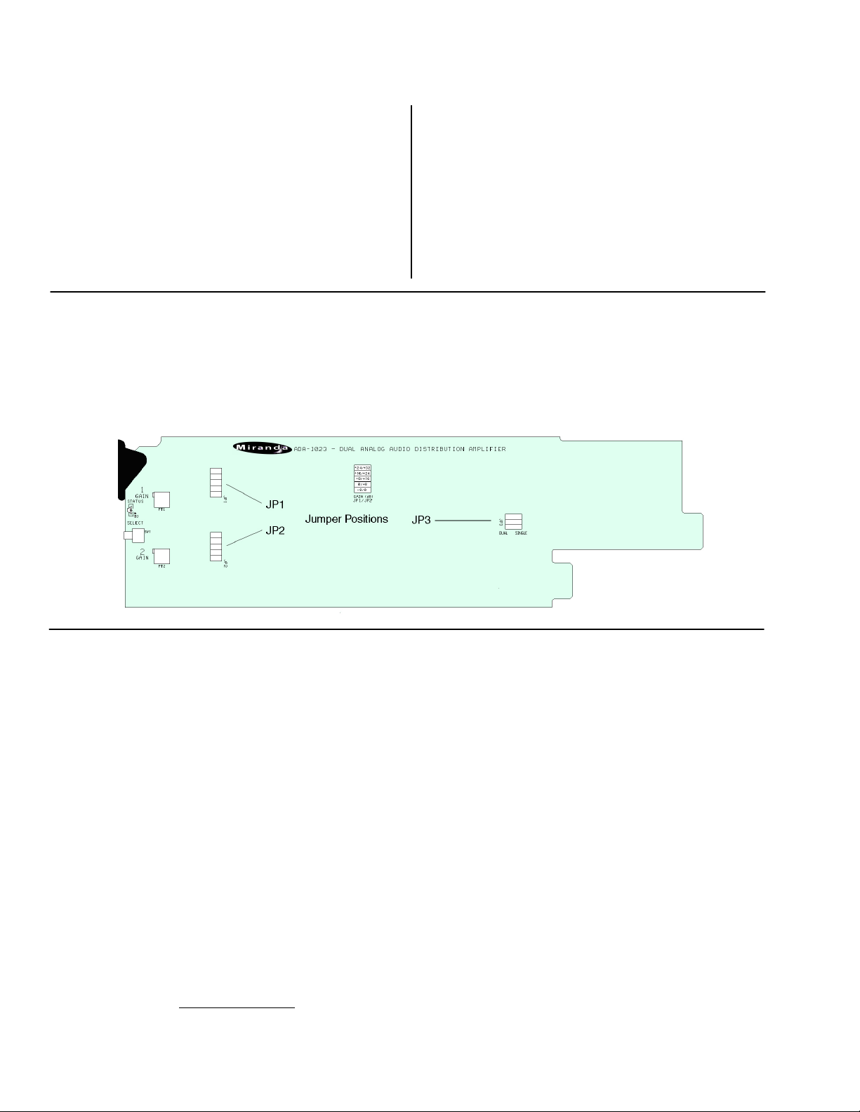
Mode selection and Gain Adjustment
The ADA-1023 can operate as a single-input, 8-output DA, or as a dual-input, 4-output DA. Select the operating mode using jumper J3,
located on the card (see figure below for jumper location)
The gain of the two audio input channels can be set using a two-step process. First, select the gain range using on-board jumpers J1 and J2
The gain range can be selected from the following choices: -8 to 0db, 0 to 8 db. 8 to 16 dB, 16 to 24 dB, 24 to 32 dB. Once the range is
selected, use the trim pots accessible from the front card edge to adjust the gain within the selected range.
ALARM REPORT: The default value NONE is assigned to
errors. Alarm relay activation will be associated with an error
when GPI is set.
VERSION menu
UC = Vxxx Microcontroller firmware version
FACTORY DEFAULT menu
RESTORE:
adjustable parameters to a factory-preset state (indicated in
BOLD the menu chart above).
Select RESTORE to reset all of the menu-
COMPLIANCE
This unit generates, uses, and can radiate radio frequency energy. If the unit is not properly installed and used in accordance with this guide,
it may cause interference with radio communications. Operation with non-certified peripheral devices is likely to result in interference with
radio and television reception. This equipment has been tested and complies with the limits in accordance with the specifications in:
FCC Part 15, Subpart B; EN55022; EN50204; EN61000-3-2, -3; EN61000-4-2, -3, -4, -5, -6, -11
Radio Frequency Interference and Immunity
CONTACT MIRANDA
For technical assistance, please contact the Miranda Technical support centre nearest you:
Americas
Telephone:
+1-800-224-7882
e-mail:
techsupp@miranda.com
Asia
Telephone:
+81-3-5730-2987
e-mail:
asiatech@miranda.com
Europe, Middle East,
Africa, UK
Telephone:
+44 (0) 1491 820222
e-mail:
eurotech@miranda.com
France (only)
Telephone:
+33 (0) 1 55 86 87 88
e-mail:
eurotech@miranda.com
Visit our web site at www.miranda.com
Page 4 of 4 ADA-1023
 Loading...