

Page 1
Acappella
ROUTING SYSTEM
Instruction Manual
Software Version 3.2.4
071830008
MARCH 2011
Page 2

Affiliate with the N.V. KEMA in The Netherlands
CERTIFICATE
Certificate Number: 510040.001
The Quality System of:
Thomson Inc, and its worLdwide Grass Valley division affiliates DBA
GRASS VALLEY
Headquarters
400 Providence Mine Rd
Nevada City, CA 95959
United States
15655 SW Greystone Ct.
Beaverton, OR 97006
United States
10 Presidential Way
Suite 300
Woburn, MA 01801
United States
Kapittelweg 10
4827 HG Breda
The Nederlands
7140 Baymeadows Way
Ste 101
Jacksonville, FL 32256
United States
2300 So. Decker Lake Blvd.
Salt Lake City, UT 84119
United States
Rue du Clos Courtel
CS 31719
35517 Cesson-Sevigné Cedex
France
1 rue de l’Hautil
Z.I. des Boutries BP 150
78702 Conflans-Sainte
Honorine Cedex
France
Technopole Brest-Iroise
Site de la Pointe du Diable
CS 73808
29238 Brest Cedex 3
France
40 Rue de Bray
2 Rue des Landelles
35510 Cesson Sevigné
France
Spinnereistrasse 5
CH-5300 Turgi
Switzerland
Brunnenweg 9
D-64331 Weiterstadt
Germany
Carl-Benz-Strasse 6-8
67105 Schifferstadt
Germany
Including its implementation, meets the requirements of the standard:
ISO 9001:2008
Scope:
The design, manufacture and support of video and audio hardware and software products and
related systems
.
This Certificate is valid until: June 14, 2012
This Certificate is valid as of: June 14, 2009
Certified for the first time: June 14, 2000
H. Pierre Sallé
President
KEMA-Registered Quality
The method of operation for quality certification is defined in the KEMA General Terms
And Conditions For Quality And Environmental Management Systems Certifications.
Integral publication of this certificate is allowed.
KEMA-Registered Quality, Inc.
4377 County Line Road
Chalfont, PA 18914
Ph: (215)997-4519
Fax: (215)997-3809
CRT 001 073004
Accredited By:
ANAB
Page 3

Acappella
ROUTING SYSTEM
Instruction Manual
Software Version 3.2.4
071830008
MARCH 2011
Page 4
Contacting Grass Valley
International
Support Centers
Local Support
Centers
(available
during normal
business hours)
France
24 x 7
Australia and New Zealand: +61 1300 721 495 Central/South America: +55 11 5509 3443
Middle East: +971 4 299 64 40 Near East and Africa: +800 8080 2020 or +33 1 48 25 20 20
Europe
+800 8080 2020 or +33 1 48 25 20 20
Hong Kong, Taiwan, Korea, Macau: +852 2531 3058 Indian Subcontinent: +91 22 24933476
Asia
Southeast Asia/Malaysia: +603 7805 3884 Southeast Asia/Singapore: +65 6379 1313
China: +861 0660 159 450 Japan: +81 3 5484 6868
Belarus, Russia, Tadzikistan, Ukraine, Uzbekistan: +7 095 2580924 225 Switzerland: +41 1 487 80 02
S. Europe/Italy-Roma: +39 06 87 20 35 28 -Milan: +39 02 48 41 46 58 S. Europe/Spain: +34 91 512 03 50
Benelux/Belgium: +32 (0) 2 334 90 30 Benelux/Netherlands: +31 (0) 35 62 38 42 1 N. Europe: +45 45 96 88 70
Germany, Austria, Eastern Europe: +49 6150 104 444 UK, Ireland, Israel: +44 118 923 0499
Copyright © Grass Valley USA, LLC. All rights reserved.
This product may be covered by one or more U.S. and foreign patents.
United States/Canada
24 x 7
+1 800 547 8949 or +1 530 478 4148
Grass Valley Web Site
The www.grassvalley.com web site offers the following:
Online User Documentation — Current versions of product catalogs, brochures,
data sheets, ordering guides, planning guides, manuals, and release notes
in .pdf format can be downloaded.
FAQ Database — Solutions to problems and troubleshooting efforts can be
found by searching our Frequently Asked Questions (FAQ) database.
Software Downloads — Download software updates, drivers, and patches.
4 Acappella — Instruction Manual
Page 5

Contents
Preface. . . . . . . . . . . . . . . . . . . . . . . . . . . . . . . . . . . . . . . . . . . . . . . . . . . . . . . . . . . . . . . . . . . . . 9
About This Manual . . . . . . . . . . . . . . . . . . . . . . . . . . . . . . . . . . . . . . . . . . . . . . . . . . . . . 9
Safety Summary. . . . . . . . . . . . . . . . . . . . . . . . . . . . . . . . . . . . . . . . . . . . . . . . . . . . . . . . . 11
Safety Terms and Symbols. . . . . . . . . . . . . . . . . . . . . . . . . . . . . . . . . . . . . . . . . . . . . . 11
Terms in This Manual. . . . . . . . . . . . . . . . . . . . . . . . . . . . . . . . . . . . . . . . . . . . . . . . 11
Terms on the Product . . . . . . . . . . . . . . . . . . . . . . . . . . . . . . . . . . . . . . . . . . . . . . . . 11
Symbols on the Product . . . . . . . . . . . . . . . . . . . . . . . . . . . . . . . . . . . . . . . . . . . . . . 12
Warnings . . . . . . . . . . . . . . . . . . . . . . . . . . . . . . . . . . . . . . . . . . . . . . . . . . . . . . . . . . . . 12
Cautions . . . . . . . . . . . . . . . . . . . . . . . . . . . . . . . . . . . . . . . . . . . . . . . . . . . . . . . . . . . . . 13
Regulatory Notices . . . . . . . . . . . . . . . . . . . . . . . . . . . . . . . . . . . . . . . . . . . . . . . . . . . . . . 23
Certifications and Compliances . . . . . . . . . . . . . . . . . . . . . . . . . . . . . . . . . . . . . . . . . 23
FCC Emission Control . . . . . . . . . . . . . . . . . . . . . . . . . . . . . . . . . . . . . . . . . . . . . . . 23
Canadian EMC Notice of Compliance . . . . . . . . . . . . . . . . . . . . . . . . . . . . . . . . . . 23
EN55103-1/2 Class A Warning . . . . . . . . . . . . . . . . . . . . . . . . . . . . . . . . . . . . . . . . 24
Safety Certification . . . . . . . . . . . . . . . . . . . . . . . . . . . . . . . . . . . . . . . . . . . . . . . . . . 24
Section 1 — System Overview. . . . . . . . . . . . . . . . . . . . . . . . . . . . . . . . . . . . . . . . . . 25
Introduction . . . . . . . . . . . . . . . . . . . . . . . . . . . . . . . . . . . . . . . . . . . . . . . . . . . . . . . . . . 25
Features. . . . . . . . . . . . . . . . . . . . . . . . . . . . . . . . . . . . . . . . . . . . . . . . . . . . . . . . . . . . 26
Hardware Description . . . . . . . . . . . . . . . . . . . . . . . . . . . . . . . . . . . . . . . . . . . . . . . . . 27
Front Panels . . . . . . . . . . . . . . . . . . . . . . . . . . . . . . . . . . . . . . . . . . . . . . . . . . . . . . . . 27
Backplanes . . . . . . . . . . . . . . . . . . . . . . . . . . . . . . . . . . . . . . . . . . . . . . . . . . . . . . . . . 29
Video Configuration (Digital and Analog) . . . . . . . . . . . . . . . . . . . . . . . . . . . . 29
Digital Audio Configuration . . . . . . . . . . . . . . . . . . . . . . . . . . . . . . . . . . . . . . . . 31
Analog Audio Configuration. . . . . . . . . . . . . . . . . . . . . . . . . . . . . . . . . . . . . . . . 33
Acappella Router and Remote Panel Variations. . . . . . . . . . . . . . . . . . . . . . . . 35
A84HR-CLP 8x4 HD Router Clean Switch Limitations . . . . . . . . . . . . . . . . . . . . . 36
Prelude Configuration . . . . . . . . . . . . . . . . . . . . . . . . . . . . . . . . . . . . . . . . . . . . . . . 36
Frame Sync Validated for HD Operation. . . . . . . . . . . . . . . . . . . . . . . . . . . . . . . . 36
Section 2 — Installation. . . . . . . . . . . . . . . . . . . . . . . . . . . . . . . . . . . . . . . . . . . . . . . . . 37
Acappella Frame Rack Installation. . . . . . . . . . . . . . . . . . . . . . . . . . . . . . . . . . . . . . . 37
Remote Panel Rack Installation. . . . . . . . . . . . . . . . . . . . . . . . . . . . . . . . . . . . . . . . . . 38
Acappella Cabling. . . . . . . . . . . . . . . . . . . . . . . . . . . . . . . . . . . . . . . . . . . . . . . . . . . . . 39
Analog Audio Pinouts . . . . . . . . . . . . . . . . . . . . . . . . . . . . . . . . . . . . . . . . . . . . . . . 41
Control Cabling . . . . . . . . . . . . . . . . . . . . . . . . . . . . . . . . . . . . . . . . . . . . . . . . . . . . . 42
Ethernet Cabling . . . . . . . . . . . . . . . . . . . . . . . . . . . . . . . . . . . . . . . . . . . . . . . . . . . . 42
Reference Cabling . . . . . . . . . . . . . . . . . . . . . . . . . . . . . . . . . . . . . . . . . . . . . . . . . . . 43
Remote Panel Cabling . . . . . . . . . . . . . . . . . . . . . . . . . . . . . . . . . . . . . . . . . . . . . . . . . 44
Power . . . . . . . . . . . . . . . . . . . . . . . . . . . . . . . . . . . . . . . . . . . . . . . . . . . . . . . . . . . . . . . 44
Digital Frames . . . . . . . . . . . . . . . . . . . . . . . . . . . . . . . . . . . . . . . . . . . . . . . . . . . . . . 44
Analog Frames. . . . . . . . . . . . . . . . . . . . . . . . . . . . . . . . . . . . . . . . . . . . . . . . . . . . . . 45
Acappella — Instruction Manual 5
Page 6

Contents
Defaults for Plug and Play . . . . . . . . . . . . . . . . . . . . . . . . . . . . . . . . . . . . . . . . . . . . . 45
Section 3 — Panel Operation. . . . . . . . . . . . . . . . . . . . . . . . . . . . . . . . . . . . . . . . . . . 47
Enable Button . . . . . . . . . . . . . . . . . . . . . . . . . . . . . . . . . . . . . . . . . . . . . . . . . . . . . . . . 47
Enable Button Action . . . . . . . . . . . . . . . . . . . . . . . . . . . . . . . . . . . . . . . . . . . . . . . . 47
Protect Button . . . . . . . . . . . . . . . . . . . . . . . . . . . . . . . . . . . . . . . . . . . . . . . . . . . . . . . . 48
Protect Button Action. . . . . . . . . . . . . . . . . . . . . . . . . . . . . . . . . . . . . . . . . . . . . . . . 48
Source Button . . . . . . . . . . . . . . . . . . . . . . . . . . . . . . . . . . . . . . . . . . . . . . . . . . . . . . . . 49
Single Source Button Action . . . . . . . . . . . . . . . . . . . . . . . . . . . . . . . . . . . . . . . . . . 49
Multiple Source Button Action (Local Panel). . . . . . . . . . . . . . . . . . . . . . . . . . . . 50
Destination Button . . . . . . . . . . . . . . . . . . . . . . . . . . . . . . . . . . . . . . . . . . . . . . . . . . . . 50
Single Destination Button Action. . . . . . . . . . . . . . . . . . . . . . . . . . . . . . . . . . . . . . 50
Multiple Destination Button Action. . . . . . . . . . . . . . . . . . . . . . . . . . . . . . . . . . . . 50
Level Button . . . . . . . . . . . . . . . . . . . . . . . . . . . . . . . . . . . . . . . . . . . . . . . . . . . . . . . . . 51
Single Level Button Action . . . . . . . . . . . . . . . . . . . . . . . . . . . . . . . . . . . . . . . . . . . 51
Multi-Level Switching . . . . . . . . . . . . . . . . . . . . . . . . . . . . . . . . . . . . . . . . . . . . . . . . . 52
Section 4 — Software and Configuration. . . . . . . . . . . . . . . . . . . . . . . . . . . . . . 53
Network Configuration. . . . . . . . . . . . . . . . . . . . . . . . . . . . . . . . . . . . . . . . . . . . . . . . 53
PC Requirements . . . . . . . . . . . . . . . . . . . . . . . . . . . . . . . . . . . . . . . . . . . . . . . . . . . 53
PC Network Configuration. . . . . . . . . . . . . . . . . . . . . . . . . . . . . . . . . . . . . . . . . . . 53
Default System IP Addresses . . . . . . . . . . . . . . . . . . . . . . . . . . . . . . . . . . . . . . . . . 54
Software . . . . . . . . . . . . . . . . . . . . . . . . . . . . . . . . . . . . . . . . . . . . . . . . . . . . . . . . . . . . . 54
Software Installation. . . . . . . . . . . . . . . . . . . . . . . . . . . . . . . . . . . . . . . . . . . . . . . . . 54
NetConfig . . . . . . . . . . . . . . . . . . . . . . . . . . . . . . . . . . . . . . . . . . . . . . . . . . . . . . . . . . . 58
NetConfig Manual . . . . . . . . . . . . . . . . . . . . . . . . . . . . . . . . . . . . . . . . . . . . . . . . . . 60
Setting IP Addresses. . . . . . . . . . . . . . . . . . . . . . . . . . . . . . . . . . . . . . . . . . . . . . . . . 60
Load Software . . . . . . . . . . . . . . . . . . . . . . . . . . . . . . . . . . . . . . . . . . . . . . . . . . . . . . 63
Web Browser Interface. . . . . . . . . . . . . . . . . . . . . . . . . . . . . . . . . . . . . . . . . . . . . . . . . 65
Acappella Configuration Pages . . . . . . . . . . . . . . . . . . . . . . . . . . . . . . . . . . . . . . . . . 66
Router Configuration . . . . . . . . . . . . . . . . . . . . . . . . . . . . . . . . . . . . . . . . . . . . . . . . 66
Router Status Page . . . . . . . . . . . . . . . . . . . . . . . . . . . . . . . . . . . . . . . . . . . . . . . . 66
Router System Configuration Page . . . . . . . . . . . . . . . . . . . . . . . . . . . . . . . . . . 67
Router Network Configuration Page. . . . . . . . . . . . . . . . . . . . . . . . . . . . . . . . . 69
Router Video Configuration Page (Non Frame Sync) . . . . . . . . . . . . . . . . . . . 71
Router Video Configuration Page (With Frame Sync) . . . . . . . . . . . . . . . . . . 73
Video Frame Sync Configuration Web Page (Frame Sync Systems Only). . 74
Router AES Configuration Page . . . . . . . . . . . . . . . . . . . . . . . . . . . . . . . . . . . . . 78
Router Remote Configuration Page . . . . . . . . . . . . . . . . . . . . . . . . . . . . . . . . . . 82
Router Reference Configuration Page . . . . . . . . . . . . . . . . . . . . . . . . . . . . . . . . 88
Router Factory Defaults Page . . . . . . . . . . . . . . . . . . . . . . . . . . . . . . . . . . . . . . . 90
Acap Router Applications Page . . . . . . . . . . . . . . . . . . . . . . . . . . . . . . . . . . . . . 91
Maintenance Page . . . . . . . . . . . . . . . . . . . . . . . . . . . . . . . . . . . . . . . . . . . . . . . . . 92
Remote Panel Configuration. . . . . . . . . . . . . . . . . . . . . . . . . . . . . . . . . . . . . . . . . . 93
Panel Description Page. . . . . . . . . . . . . . . . . . . . . . . . . . . . . . . . . . . . . . . . . . . . . 93
Remote Panel System Configuration . . . . . . . . . . . . . . . . . . . . . . . . . . . . . . . . . 94
Remote Panel Network Configuration . . . . . . . . . . . . . . . . . . . . . . . . . . . . . . . 96
Saving Settings. . . . . . . . . . . . . . . . . . . . . . . . . . . . . . . . . . . . . . . . . . . . . . . . . . . . 97
Remote Panel Factory Defaults. . . . . . . . . . . . . . . . . . . . . . . . . . . . . . . . . . . . . . 98
Remote Panel Acappella Destination Configuration. . . . . . . . . . . . . . . . . . . . 99
Remote Panel Router Configuration . . . . . . . . . . . . . . . . . . . . . . . . . . . . . . . . 100
External System Control of Acappella . . . . . . . . . . . . . . . . . . . . . . . . . . . . . . . . . . 101
6 Acappella — Instruction Manual
Page 7

Serial Control . . . . . . . . . . . . . . . . . . . . . . . . . . . . . . . . . . . . . . . . . . . . . . . . . . . . . . 101
Encore Control . . . . . . . . . . . . . . . . . . . . . . . . . . . . . . . . . . . . . . . . . . . . . . . . . . . . . 102
Indigo AV Mixer HD Expansion . . . . . . . . . . . . . . . . . . . . . . . . . . . . . . . . . . . . . . . 102
Router Reference Configuration . . . . . . . . . . . . . . . . . . . . . . . . . . . . . . . . . . . . . . 102
Router Video Configuration . . . . . . . . . . . . . . . . . . . . . . . . . . . . . . . . . . . . . . . . . 103
Section 5 — Maintenance and Troubleshooting. . . . . . . . . . . . . . . . . . . . . . 105
Field Replaceable Units . . . . . . . . . . . . . . . . . . . . . . . . . . . . . . . . . . . . . . . . . . . . . . . 105
Troubleshooting . . . . . . . . . . . . . . . . . . . . . . . . . . . . . . . . . . . . . . . . . . . . . . . . . . . . . 105
Check Connections . . . . . . . . . . . . . . . . . . . . . . . . . . . . . . . . . . . . . . . . . . . . . . . . . 105
Check Inputs . . . . . . . . . . . . . . . . . . . . . . . . . . . . . . . . . . . . . . . . . . . . . . . . . . . . . . 105
Problems and Solutions . . . . . . . . . . . . . . . . . . . . . . . . . . . . . . . . . . . . . . . . . . . . . . . 106
Switching Problems. . . . . . . . . . . . . . . . . . . . . . . . . . . . . . . . . . . . . . . . . . . . . . . . . 106
Switching Latency . . . . . . . . . . . . . . . . . . . . . . . . . . . . . . . . . . . . . . . . . . . . . . . . 106
SNMP Monitoring. . . . . . . . . . . . . . . . . . . . . . . . . . . . . . . . . . . . . . . . . . . . . . . . . . . . 106
SNMP Managers . . . . . . . . . . . . . . . . . . . . . . . . . . . . . . . . . . . . . . . . . . . . . . . . . . . 106
NetCentral SNMP Manager . . . . . . . . . . . . . . . . . . . . . . . . . . . . . . . . . . . . . . . . 106
Third Party SNMP Managers. . . . . . . . . . . . . . . . . . . . . . . . . . . . . . . . . . . . . . . 107
Acappella SNMP Agent Licensing . . . . . . . . . . . . . . . . . . . . . . . . . . . . . . . . . . . . 107
Monitored Acappella Matrix Parameters . . . . . . . . . . . . . . . . . . . . . . . . . . . . . . 109
Acappella Matrix Traps . . . . . . . . . . . . . . . . . . . . . . . . . . . . . . . . . . . . . . . . . . . . . 110
Source and Destination Signal Loss Configuration . . . . . . . . . . . . . . . . . . . . 111
Contents
Appendix A — Specifications . . . . . . . . . . . . . . . . . . . . . . . . . . . . . . . . . . . . . . . . . . 115
Mechanical and Power . . . . . . . . . . . . . . . . . . . . . . . . . . . . . . . . . . . . . . . . . . . . . . . . 115
Video Specifications . . . . . . . . . . . . . . . . . . . . . . . . . . . . . . . . . . . . . . . . . . . . . . . . . . 115
Video Reference. . . . . . . . . . . . . . . . . . . . . . . . . . . . . . . . . . . . . . . . . . . . . . . . . . . . 115
SD Digital Video . . . . . . . . . . . . . . . . . . . . . . . . . . . . . . . . . . . . . . . . . . . . . . . . . . . 116
Wideband Digital Video. . . . . . . . . . . . . . . . . . . . . . . . . . . . . . . . . . . . . . . . . . . . . 116
Analog Video . . . . . . . . . . . . . . . . . . . . . . . . . . . . . . . . . . . . . . . . . . . . . . . . . . . . . . 117
Audio Specifications. . . . . . . . . . . . . . . . . . . . . . . . . . . . . . . . . . . . . . . . . . . . . . . . . . 118
AES Digital Audio. . . . . . . . . . . . . . . . . . . . . . . . . . . . . . . . . . . . . . . . . . . . . . . . . . 118
Analog Audio. . . . . . . . . . . . . . . . . . . . . . . . . . . . . . . . . . . . . . . . . . . . . . . . . . . . . . 118
Appendix B — Native Protocol. . . . . . . . . . . . . . . . . . . . . . . . . . . . . . . . . . . . . . . . . 121
Index . . . . . . . . . . . . . . . . . . . . . . . . . . . . . . . . . . . . . . . . . . . . . . . . . . . . . . . . . . . . . . . . . . . . . 123
Acappella — Instruction Manual 7
Page 8

Contents
8 Acappella — Instruction Manual
Page 9

Preface
About This Manual
This manual provides installation, configuration, operation, safety, and
regulatory information for the Acappella small router products.
Acappella — Instruction Manual 9
Page 10

Preface
10 Acappella — Instruction Manual
Page 11

Safety Summary
Read and follow the important safety information below, noting especially
those instructions related to risk of fire, electric shock or injury to persons.
Additional specific warnings not listed here may be found throughout the
manual.
WARNING Any instructions in this manual that require opening the equipment cover
or enclosure are for use by qualified service personnel only. To reduce the
risk of electric shock, do not perform any servicing other than that con
tained in the operating instructions unless you are qualified to do so.
Safety Terms and Symbols
Terms in This Manual
-
Safety-related statements may appear in this manual in the following form:
WARNING Warning statements identify conditions or practices that may result in per-
sonal injury or loss of life.
CAUTION Caution statements identify conditions or practices that may result in damage
to equipment or other property, or which may cause equipment crucial to
your business environment to become temporarily non-operational.
Terms on the Product
The following terms may appear on the product:
DANGER — A personal injury hazard is immediately accessible as you read
the marking.
WARNING — A personal injury hazard exists but is not immediately acces-
sible as you read the marking.
CAUTION — A hazard to property, product, and other equipment is present.
Acappella — Instruction Manual 11
Page 12
Safety Summary
Symbols on the Product
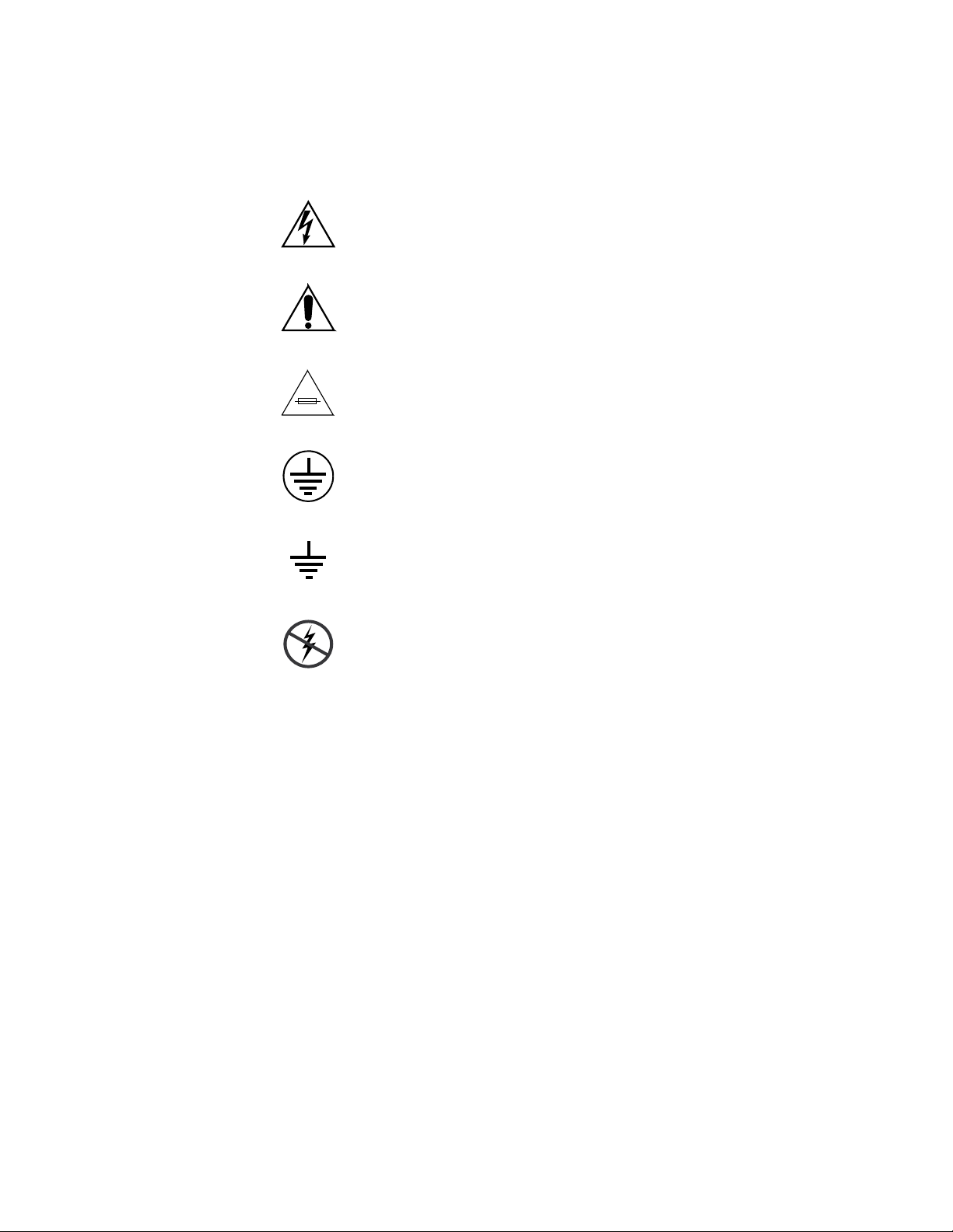
The following symbols may appear on the product:
Indicates that dangerous high voltage is present within the
equipment enclosure that may be of sufficient magnitude to
constitute a risk of electric shock.
Indicates that user, operator or service technician should refer
to product manual(s) for important operating, maintenance,
or service instructions.
This is a prompt to note fuse rating when replacing fuse(s).
The fuse referenced in the text must be replaced with one
having the ratings indicated.
Identifies a protective grounding terminal which must be connected to earth ground prior to making any other equipment
connections.
Warnings
Identifies an external protective grounding terminal which
may be connected to earth ground as a supplement to an
internal grounding terminal.
Indicates that static sensitive components are present which
may be damaged by electrostatic discharge. Use anti-static
procedures, equipment and surfaces during servicing.
The following warning statements identify conditions or practices that can
result in personal injury or loss of life:
Dangerous voltage or current may be present — Disconnect power and remove
battery (if applicable) before removing protective panels, soldering, or
replacing components.
Do not service alone — Do not internally service this product unless another
person capable of rendering first aid and resuscitation is present.
Remove jewelry — Prior to servicing, remove jewelry such as rings, watches,
and other metallic objects.
Avoid exposed circuitry — Do not touch exposed connections, components or
circuitry when power is present.
12 Acappella — Instruction Manual
Page 13

Safety Summary
Use proper power cord — Use only the power cord supplied or specified for
this product.
Ground product — Connect the grounding conductor of the power cord to
earth ground.
Operate only with covers and enclosure panels in place — Do not operate this
product when covers or enclosure panels are removed.
Use correct fuse — Use only the fuse type and rating specified for this
product.
Use only in dry environment — Do not operate in wet or damp conditions.
Use only in non-explosive environment — Do not operate this product in an
explosive atmosphere.
High leakage current may be present — Earth connection of product is essential
before connecting power.
Dual power supplies may be present — Be certain to plug each power supply
cord into a separate branch circuit employing a separate service ground.
Disconnect both power supply cords prior to servicing.
Cautions
Double pole neutral fusing — Disconnect mains power prior to servicing.
Use proper lift points — Do not use door latches to lift or move equipment.
Avoid mechanical hazards — Allow all rotating devices to come to a stop before
servicing.
The following caution statements identify conditions or practices that can
result in damage to equipment or other property:
Use correct power source — Do not operate this product from a power source
that applies more than the voltage specified for the product.
Use correct voltage setting — If this product lacks auto-ranging power sup-
plies, before applying power ensure that the each power supply is set to
match the power source.
Provide proper ventilation — To prevent product overheating, provide equip-
ment ventilation in accordance with installation instructions.
Use anti-static procedures — Static sensitive components are present which
may be damaged by electrostatic discharge. Use anti-static procedures,
equipment and surfaces during servicing.
Do not operate with suspected equipment failure — If you suspect product damage
or equipment failure, have the equipment inspected by qualified service
personnel.
Acappella — Instruction Manual 13
Page 14

Safety Summary
Ensure mains disconnect — If mains switch is not provided, the power cord(s)
of this equipment provide the means of disconnection. The socket outlet
must be installed near the equipment and must be easily accessible. Verify
that all mains power is disconnected before installing or removing power
supplies and/or options.
Route cable properly — Route power cords and other cables so that they ar not
likely to be damaged. Properly support heavy cable bundles to avoid con
nector damage.
Use correct power supply cords — Power cords for this equipment, if provided,
meet all North American electrical codes. Operation of this equipment at
voltages exceeding 130 VAC requires power supply cords which comply
with NEMA configurations. International power cords, if provided, have
the approval of the country of use.
Use correct replacement battery — This product may contain batteries. To
reduce the risk of explosion, check polarity and replace only with the same
or equivalent type recommended by manufacturer. Dispose of used bat
teries according to the manufacturer’s instructions.
Troubleshoot only to board level — Circuit boards in this product are densely
populated with surface mount technology (SMT) components and applica
tion specific integrated circuits (ASICS). As a result, circuit board repair at
the component level is very difficult in the field, if not impossible. For war
ranty compliance, do not troubleshoot systems beyond the board level.
-
-
-
-
14 Acappella — Instruction Manual
Page 15

Sicherheit – Überblick
Lesen und befolgen Sie die wichtigen Sicherheitsinformationen dieses
Abschnitts. Beachten Sie insbesondere die Anweisungen bezüglich
Brand-, Stromschlag- und Verletzungsgefahren. Weitere spezifische, hier
nicht aufgeführte Warnungen finden Sie im gesamten Handbuch.
WARNUNG Alle Anweisungen in diesem Handbuch, die das Abnehmen der
Geräteabdeckung oder des Gerätegehäuses erfordern, dürfen nur von
qualifiziertem Servicepersonal ausgeführt werden. Um die
Stromschlaggefahr zu verringern, führen Sie keine Wartungsarbeiten
außer den in den Bedienungsanleitungen genannten Arbeiten aus, es sei
denn, Sie besitzen die entsprechende Qualifikationen für diese Arbeiten.
Sicherheit – Begriffe und Symbole
Safety Summary
In diesem Handbuch verwendete Begriffe
Sicherheitsrelevante Hinweise können in diesem Handbuch in der folgenden Form auftauchen:
WARNUNG Warnungen weisen auf Situationen oder Vorgehensweisen hin, die
Verletzungs- oder Lebensgefahr bergen.
VORSICHT Vorsichtshinweise weisen auf Situationen oder Vorgehensweisen hin, die zu
Schäden an Ausrüstungskomponenten oder anderen Gegenständen oder
zum zeitweisen Ausfall wichtiger Komponenten in der Arbeitsumgebung
führen können.
Hinweise am Produkt
Die folgenden Hinweise können sich am Produkt befinden:
GEFAHR — Wenn Sie diesen Begriff lesen, besteht ein unmittelbares Verlet-
zungsrisiko.
WARNUNG — Wenn Sie diesen Begriff lesen, besteht ein mittelbares Verlet-
zungsrisiko.
VORSICHT — Es besteht ein Risiko für Objekte in der Umgebung, den Mixer
selbst oder andere Ausrüstungskomponenten.
Acappella — Instruction Manual 15
Page 16
Safety Summary
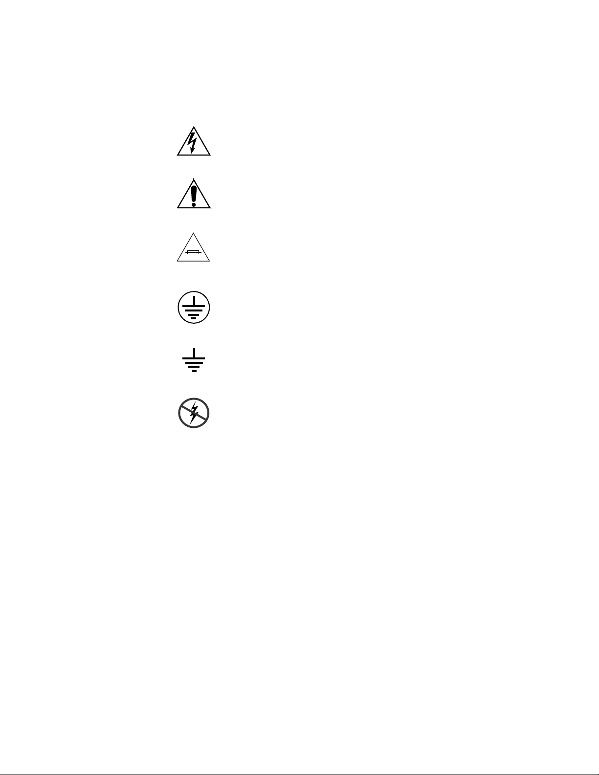
Symbole am Produkt
Die folgenden Symbole können sich am Produkt befinden:
Weist auf eine gefährliche Hochspannung im Gerätegehäuse
hin, die stark genug sein kann, um eine Stromschlaggefahr
darzustellen.
Weist darauf hin, dass der Benutzer, Bediener oder Servicetechniker wichtige Bedienungs-, Wartungs- oder Serviceanweisungen in den Produkthandbüchern lesen sollte.
Dies ist eine Aufforderung, beim Wechsel von Sicherungen
auf deren Nennwert zu achten. Die im Text angegebene Sich
erung muss durch eine Sicherung ersetzt werden, die die
angegebenen Nennwerte besitzt.
Weist auf eine Schutzerdungsklemme hin, die mit dem
Erdungskontakt verbunden werden muss, bevor weitere Aus
rüstungskomponenten angeschlossen werden.
-
-
Warnungen
Weist auf eine externe Schutzerdungsklemme hin, die als
Ergänzung zu einem internen Erdungskontakt an die Erde
angeschlossen werden kann.
Weist darauf hin, dass es statisch empfindliche Komponenten
gibt, die durch eine elektrostatische Entladung beschädigt
werden können. Verwenden Sie antistatische Prozeduren,
Ausrüstung und Oberflächen während der Wartung.
Die folgenden Warnungen weisen auf Bedingungen oder Vorgehensweisen
hin, die Verletzungs- oder Lebensgefahr bergen:
Gefährliche Spannungen oder Ströme — Schalten Sie den Strom ab, und ent-
fernen Sie ggf. die Batterie, bevor sie Schutzabdeckungen abnehmen, löten
oder Komponenten austauschen.
Servicearbeiten nicht alleine ausführen — Führen Sie interne Servicearbeiten nur
aus, wenn eine weitere Person anwesend ist, die erste Hilfe leisten und
Wiederbelebungsmaßnahmen einleiten kann.
Schmuck abnehmen — Legen Sie vor Servicearbeiten Schmuck wie Ringe,
Uhren und andere metallische Objekte ab.
16 Acappella — Instruction Manual
Page 17

Safety Summary
Keine offen liegenden Leiter berühren — Berühren Sie bei eingeschalteter Strom-
zufuhr keine offen liegenden Leitungen, Komponenten oder Schaltungen.
Richtiges Netzkabel verwenden — Verwenden Sie nur das mitgelieferte Netzk-
abel oder ein Netzkabel, das den Spezifikationen für dieses Produkt
entspricht.
Gerät erden — Schließen Sie den Erdleiter des Netzkabels an den Erdung-
skontakt an.
Gerät nur mit angebrachten Abdeckungen und Gehäuseseiten betreiben — Schalten Sie
dieses Gerät nicht ein, wenn die Abdeckungen oder Gehäuseseiten entfernt
wurden.
Richtige Sicherung verwenden — Verwenden Sie nur Sicherungen, deren Typ
und Nennwert den Spezifikationen für dieses Produkt entsprechen.
Gerät nur in trockener Umgebung verwenden — Betreiben Sie das Gerät nicht in
nassen oder feuchten Umgebungen.
Gerät nur verwenden, wenn keine Explosionsgefahr besteht — Verwenden Sie dieses
Produkt nur in Umgebungen, in denen keinerlei Explosionsgefahr besteht.
Hohe Kriechströme — Das Gerät muss vor dem Einschalten unbedingt geerdet
werden.
Doppelte Spannungsversorgung kann vorhanden sein — Schließen Sie die beiden
Anschlußkabel an getrennte Stromkreise an. Vor Servicearbeiten sind beide
Anschlußkabel vom Netz zu trennen.
Zweipolige, neutrale Sicherung — Schalten Sie den Netzstrom ab, bevor Sie mit
den Servicearbeiten beginnen.
Fassen Sie das Gerät beim Transport richtig an — Halten Sie das Gerät beim Trans-
port nicht an Türen oder anderen beweglichen Teilen fest.
Gefahr durch mechanische Teile — Warten Sie, bis der Lüfter vollständig zum
Halt gekommen ist, bevor Sie mit den Servicearbeiten beginnen.
Vorsicht
Die folgenden Vorsichtshinweise weisen auf Bedingungen oder Vorgehensweisen hin, die zu Schäden an Ausrüstungskomponenten oder
anderen Gegenständen führen können:
Gerät nicht öffnen — Durch das unbefugte Öffnen wird die Garantie ungültig.
Richtige Spannungsquelle verwenden — Betreiben Sie das Gerät nicht an einer
Spannungsquelle, die eine höhere Spannung liefert als in den Spezifika
tionen für dieses Produkt angegeben.
Gerät ausreichend belüften — Um eine Überhitzung des Geräts zu vermeiden,
müssen die Ausrüstungskomponenten entsprechend den Installationsan
Acappella — Instruction Manual 17
-
-
Page 18

Safety Summary
weisungen belüftet werden. Legen Sie kein Papier unter das Gerät. Es
könnte die Belüftung behindern. Platzieren Sie das Gerät auf einer ebenen
Oberfläche.
Antistatische Vorkehrungen treffen — Es gibt statisch empfindliche Kompo-
nenten, die durch eine elektrostatische Entladung beschädigt werden kön-
nen. Verwenden Sie antistatische Prozeduren, Ausrüstung und
Oberflächen während der Wartung.
CF-Karte nicht mit einem PC verwenden — Die CF-Karte ist speziell formatiert.
Die auf der CF-Karte gespeicherte Software könnte gelöscht werden.
Gerät nicht bei eventuellem Ausrüstungsfehler betreiben — Wenn Sie einen Produk-
tschaden oder Ausrüstungsfehler vermuten, lassen Sie die Komponente
von einem qualifizierten Servicetechniker untersuchen.
Kabel richtig verlegen — Verlegen Sie Netzkabel und andere Kabel so, dass Sie
nicht beschädigt werden. Stützen Sie schwere Kabelbündel ordnungs
gemäß ab, damit die Anschlüsse nicht beschädigt werden.
Richtige Netzkabel verwenden — Wenn Netzkabel mitgeliefert wurden, erfüllen
diese alle nationalen elektrischen Normen. Der Betrieb dieses Geräts mit
Spannungen über 130 V AC erfordert Netzkabel, die NEMA-Konfigura
tionen entsprechen. Wenn internationale Netzkabel mitgeliefert wurden,
sind diese für das Verwendungsland zugelassen.
-
-
Richtige Ersatzbatterie verwenden — Dieses Gerät enthält eine Batterie. Um die
Explosionsgefahr zu verringern, prüfen Sie die Polarität und tauschen die
Batterie nur gegen eine Batterie desselben Typs oder eines gleichwertigen,
vom Hersteller empfohlenen Typs aus. Entsorgen Sie gebrauchte Batterien
entsprechend den Anweisungen des Batterieherstellers.
Das Gerät enthält keine Teile, die vom Benutzer gewartet werden können.
Wenden Sie sich bei Problemen bitte an den nächsten Händler.
18 Acappella — Instruction Manual
Page 19

Consignes de sécurité
Il est recommandé de lire, de bien comprendre et surtout de respecter les
informations relatives à la sécurité qui sont exposées ci-après, notamment
les consignes destinées à prévenir les risques d’incendie, les décharges élec
triques et les blessures aux personnes. Les avertissements complémentaires, qui ne sont pas nécessairement repris ci-dessous, mais présents dans
toutes les sections du manuel, sont également à prendre en considération.
AVERTISSEMENT Toutes les instructions présentes dans ce manuel qui concernent
l’ouverture des capots ou des logements de cet équipement sont
destinées exclusivement à des membres qualifiés du personnel de
maintenance. Afin de diminuer les risques de décharges
électriques, ne procédez à aucune intervention d’entretien autre
que celles contenues dans le manuel de l’utilisateur, à moins que
vous ne soyez habilité pour le faire.
Safety Summary
-
Consignes et symboles de sécurité
Termes utilisés dans ce manuel
Les consignes de sécurité présentées dans ce manuel peuvent apparaître
sous les formes suivantes:
AVERTISSEMENT Les avertissements signalent des conditions ou des pratiques
susceptibles d’occasionner des blessures graves, voire même
fatales.
ATTENTION Les mises en garde signalent des conditions ou des pratiques
susceptibles d’occasionner un endommagement à l’équipement ou
aux installations, ou de rendre l’équipement temporairement non
opérationnel, ce qui peut porter préjudice à vos activités.
Signalétique apposée sur le produit
La signalétique suivante peut être apposée sur le produit:
DANGER — risque de danger imminent pour l’utilisateur.
AVERTISSEMENT — Risque de danger non imminent pour l’utilisateur.
MISE EN GARDE — Risque d’endommagement du produit, des installations
ou des autres équipements.
Acappella — Instruction Manual 19
Page 20
Safety Summary
Symboles apposés sur le produit
Les symboles suivants peut être apposés sur le produit:
Signale la présence d’une tension élevée et dangereuse dans le
boîtier de l’équipement
pour constituer un risque de décharge électrique.
Signale que l’utilisateur, l’opérateur ou le technicien de maintenance doit faire référence au(x) manuel(s) pour prendre connaissance des instructions d’utilisation, de maintenance ou
d’entretien.
Il s’agit d’une invite à prendre note du calibre du fusible lors
du remplacement de ce dernier. Le fusible auquel il est fait
référence dans le texte doit être remplacé par un fusible du
même calibre.
Identifie une borne de protection de mise à la masse qui doit
être raccordée correctement avant de procéder au raccorde
ment des autres équipements.
; cette tension peut être suffisante
-
Avertissements
Identifie une borne de protection de mise à la masse qui peut
être connectée en tant que borne de mise à la masse supplé
mentaire.
Signale la présence de composants sensibles à l’électricité statique et qui sont susceptibles d’être endommagés par une
décharge électrostatique. Utilisez des procédures, des équipe
ments et des surfaces antistatiques durant les interventions
d’entretien.
Les avertissements suivants signalent des conditions ou des pratiques sus-
ceptibles d’occasionner des blessures graves, voire même fatales:
Présence possible de tensions ou de courants dangereux — Mettez hors tension,
débranchez et retirez la pile (le cas échéant) avant de déposer les couvercles
de protection, de défaire une soudure ou de remplacer des composants.
Ne procédez pas seul à une intervention d’entretien — Ne réalisez pas une interven-
tion d’entretien interne sur ce produit si une personne n’est pas présente
pour fournir les premiers soins en cas d’accident.
-
-
20 Acappella — Instruction Manual
Page 21

Safety Summary
Retirez tous vos bijoux — Avant de procéder à une intervention d’entretien,
retirez tous vos bijoux, notamment les bagues, la montre ou tout autre objet
métallique.
Évitez tout contact avec les circuits exposés — Évitez tout contact avec les connex-
ions, les composants ou les circuits exposés s’ils sont sous tension.
Utilisez le cordon d’alimentation approprié — Utilisez exclusivement le cordon
d’alimentation fourni avec ce produit ou spécifié pour ce produit.
Raccordez le produit à la masse — Raccordez le conducteur de masse du cordon
d’alimentation à la borne de masse de la prise secteur.
Utilisez le produit lorsque les couvercles et les capots sont en place — N’utilisez pas
ce produit si les couvercles et les capots sont déposés.
Utilisez le bon fusible — Utilisez exclusivement un fusible du type et du
calibre spécifiés pour ce produit.
Utilisez ce produit exclusivement dans un environnement sec — N’utilisez pas ce
produit dans un environnement humide.
Utilisez ce produit exclusivement dans un environnement non explosible — N’utilisez
pas ce produit dans un environnement dont l’atmosphère est explosible.
Mises en garde
Présence possible de courants de fuite — Un raccordement à la masse est indis-
pensable avant la mise sous tension.
Deux alimentations peuvent être présentes dans l’équipement — Assurez vous que
chaque cordon d’alimentation est raccordé à des circuits de terre séparés.
Débranchez les deux cordons d’alimentation avant toute intervention.
Fusion neutre bipolaire — Débranchez l’alimentation principale avant de pro-
céder à une intervention d’entretien.
Utilisez les points de levage appropriés — Ne pas utiliser les verrous de la porte
pour lever ou déplacer l’équipement.
Évitez les dangers mécaniques — Laissez le ventilateur s’arrêter avant de pro-
céder à une intervention d’entretien.
Les mises en garde suivantes signalent les conditions et les pratiques susceptibles d’occasionner des endommagements à l’équipement et aux installations:
N’ouvrez pas l’appareil — Toute ouverture prohibée de l’appareil aura pour
effet d’annuler la garantie.
Utilisez la source d’alimentation adéquate — Ne branchez pas ce produit à une
source d’alimentation qui utilise une tension supérieure à la tension nomi
nale spécifiée pour ce produit.
Acappella — Instruction Manual 21
-
Page 22

Safety Summary
Assurez une ventilation adéquate — Pour éviter toute surchauffe du produit,
assurez une ventilation de l’équipement conformément aux instructions
d’installation. Ne déposez aucun document sous l’appareil — ils peuvent
gêner la ventilation. Placez l’appareil sur une surface plane.
Utilisez des procédures antistatiques - Les composants sensibles à l’électricité
statique présents dans l’équipement sont susceptibles d’être endommagés
par une décharge électrostatique. Utilisez des procédures, des équipements
et des surfaces antistatiques durant les interventions d’entretien.
N’utilisez pas la carte CF avec un PC — La carte CF a été spécialement formatée.
Le logiciel enregistré sur la carte CF risque d’être effacé.
N’utilisez pas l’équipement si un dysfonctionnement est suspecté — Si vous sus-
pectez un dysfonctionnement du produit, faites inspecter celui-ci par un
membre qualifié du personnel d’entretien.
Acheminez les câbles correctement — Acheminez les câbles d’alimentation et les
autres câbles de manière à ce qu’ils ne risquent pas d’être endommagés.
Supportez correctement les enroulements de câbles afin de ne pas endom
mager les connecteurs.
-
Utilisez les cordons d’alimentation adéquats — Les cordons d’alimentation de cet
équipement, s’ils sont fournis, satisfont aux exigences de toutes les régle
mentations régionales. L’utilisation de cet équipement à des tensions
dépassant les 130
aux exigences des configurations NEMA. Les cordons internationaux, s’ils
sont fournis, ont reçu l’approbation du pays dans lequel l’équipement est
utilisé.
Utilisez une pile de remplacement adéquate — Ce produit renferme une pile. Pour
réduire le risque d’explosion, vérifiez la polarité et ne remplacez la pile que
par une pile du même type, recommandée par le fabricant. Mettez les piles
usagées au rebut conformément aux instructions du fabricant des piles.
Cette unité ne contient aucune partie qui peut faire l’objet d’un entretien
par l’utilisateur. Si un problème survient, veuillez contacter votre distribu
teur local.
V en c.a. requiert des cordons d’alimentation qui satisfont
-
-
22 Acappella — Instruction Manual
Page 23

Regulatory Notices
Certifications and Compliances
FCC Emission Control
This equipment has been tested and found to comply with the limits for a
Class A digital device, pursuant to Part 15 of the FCC Rules. These limits
are designed to provide reasonable protection against harmful interference
when the equipment is operated in a commercial environment. This equip
ment generates, uses, and can radiate radio frequency energy and, if not
installed and used in accordance with the instruction manual, may cause
harmful interference to radio communications. Operation of this equip
ment in a residential area is likely to cause harmful interference in which
case the user will be required to correct the interference at his own expense.
Changes or modifications not expressly approved by Grass Valley can
affect emission compliance and could void the user’s authority to operate
this equipment.
-
-
This device complies with Part 15 of the FCC Rules (E4 environment).
Operation is subject to the following two conditions: (1) This device may
not cause harmful interference, and (2) this device must accept any interfer
ence received, including interference that may cause undesirable operation.
Canadian EMC Notice of Compliance
This digital apparatus does not exceed the Class A limits for radio noise
emissions from digital apparatus set out in the Radio Interference Regula
tions of the Canadian Department of Communications.
Le présent appareil numérique n’emet pas de bruits radioélectriques
dépassant les limites applicables aux appareils numeriques de la classe A
préscrites dans le Règlement sur le brouillage radioélectrique édicte par le
ministère des Communications du Canada.
-
-
Acappella — Instruction Manual 23
Page 24

Regulatory Notices
EN55103-1/2 Class A Warning
Safety Certification
For products that comply with Class A. In a domestic environment this
product may cause radio interference in which case the user may be
required to take adequate measures.
This product has been evaluated for Electromagnetic Compatibility under
the EN 55103-1/2 standards for Emissions and Immunity and meets the
requirements for E4 environment.
This product’s components have been evaluated and meet the Safety Cer-
tification Standards listed in Tab le 1.
Table 1. Safety Certification Standards
Component Standard Designed/Tested for compliance with:
Acappella router
Acappella Remote panel
ANSI/UL 60950-1-2002 Safety of Information Technology Equipment, including Electrical
IEC 60950 Safety of Information Technology Equipment, including Electrical
CAN/CSA C22.2
N0. 60950-1-03 First edition
BS EN60950-2000
Business Equipment (First edition)
Business Equipment (First edition, 2001).
Safety of Information Technology Equipment, including Electrical
Business Equipment.
24 Acappella — Instruction Manual
Page 25

System Overview
Introduction
The Acappella line of small, single- and mixed-format routers is designed
for myriad broadcast and production settings, including small studios,
sports arenas, and space-constrained environments such as mobile produc
tion trucks. The Acappella matrix frame is only 1 RU, and has a 14-inch
(34.5 cm) depth for easy in-rack cabling.
The Acappella line supports local and remote control panels, via a built-in
Ethernet connection. It also includes many control panel operational
modes, such as destination gang, chop, panel enable, and destination pro
tect.
An Acappella router comes ready to operate right out of the box—just plug
it in and you can get right to work. It also supports Web browser based con
figuration for fast, easy customization.
Section 1
-
-
-
An Acappella router and remote control panels can also be integrated into
a Grass Valley Prelude or Encore routing system. This manual covers standalone Acappella systems. Refer to the separate Prelude and/or Encore doc
umentation sets for system integration information.
Acappella software release v3.2.0 and higher support the Acappella model
A84HR-CLP 8x4 HD Router with Clean Switch. This hardware provides
frame sync capability on destinations DST
requiring outputs timed to a single reference.
The Clean Switch hardware above is available for use with Grass Valley
Indigo AV Mixer, to provide eight HD-SDI inputs. The Indigo models using
this Acappella hardware are:
• INDGO1-HR-8 – Indigo AV Mixer HR Input Expansion Option
• INDGO1-HR-8-UPG – Indigo AV Mixer HR Expansion Upgrade
• INDGO1-SDHR-8-UPG – Indigo AV Mixer HR Expansion Upgrade
See A84HR-CLP 8x4 HD Router Clean Switch Limitations on page 36 for more
information.
1 and DST 2 for applications
-
Acappella — Instruction Manual 25
Page 26

Section 1 — System Overview
Features
• Single- or multi-format models, supporting:
• Many different frames available, ranging from 16 x 16 to 8 x 4.
• Clean synchronous digital audio switching.
• Redundant Power Supplies.
• Integrated Local Panel.
• Many different Remote Panels, ranging from 16 x 16 to 8 x 1.
• Wideband HD digital video from 4.0 Mb/s to 1.5 Gb/s
• SD digital video
•ASI data
• AES/EBU digital audio
• Analog Video (NTSC, PAL)
• Analog Audio (balanced)
• Standard Ethernet interface.
• Easy customization via Web browser or Grass Valley NetConfig software.
• Feature-rich digital audio processing, including sum, swap, invert,
silence generation.
• Standard RS-422 serial port for computer control, automation interface,
and operations with Grass Valley Jupiter and Series 7000 systems.
• Native Protocol support.
• SNMP support.
• Upgrade path for Ethernet operation with Grass Valley Prelude and
Encore systems.
• A84HR-CLP 8x4 HD Router with Clean Switch - provides frame sync
capability for two Acappella destinations. These outputs can be timed
in reference to the distributed Genlock reference in the frame or from an
external reference.
• Optional Indigo AV Switcher Expansion, providing 8 HD-SDI inputs
using the Clean Switch hardware above.
26 Acappella — Instruction Manual
Page 27
Hardware Description
8300_00_02r0
8300_00_08r0
8300_00_09r0
Front Panels
The front of the Acappella frame and the related remote panels will vary
with the configuration of the system. All Acappella frames can be ordered
with a local panel installed in the frame. When a local panel is ordered, the
front will appear with the button configuration that matches the Acappella
frame’s Input and Output configuration. Remote panels can be ordered in
several configurations and do not have to match the Acappella frame’s
Input and Output configuration. The panel’s appearance is related to how
many Sources and Destinations are available, not how many Levels are
used.
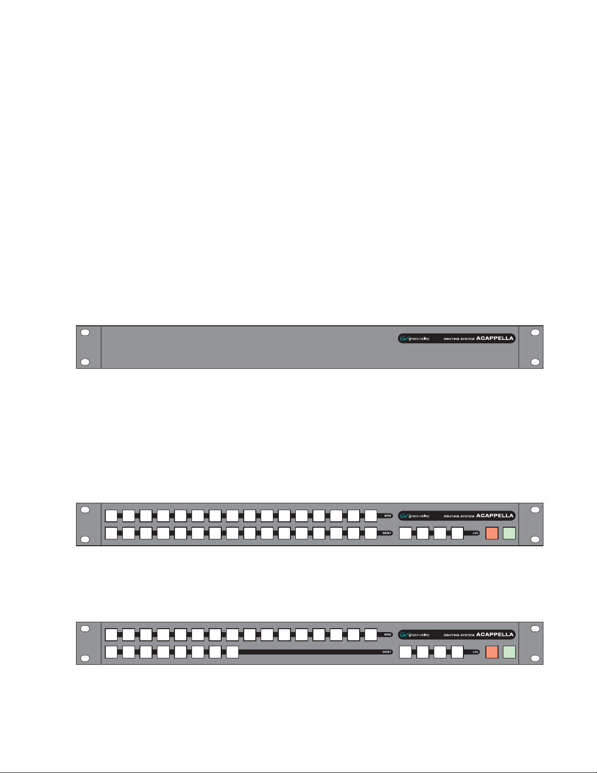
Any Acappella frame ordered without a Local Panel will appear as shown
Figure 1.
in
Figure 1. Acappella Front with no Local Panel
Hardware Description
All panel fronts (except frames with no Local Panel) will have four Level
buttons, a green Enable button, and a red Protect button. The number of
Source and Destination buttons will change depending on the frame’s con
figuration for local panels and the desired configuration for remote panels.
Figure 2 is a panel with 16 Sources and 16 Destinations.
Figure 2. 16x16 Front
Figure 3 is a panel with 16 Sources and 8 Destinations.
Figure 3. 16x8 Front
-
Acappella — Instruction Manual 27
Page 28
Section 1 — System Overview
8300_00_10r0
8300_00_11r0
8300_00_12r0
8300_00_13r0
8300_00_14r0
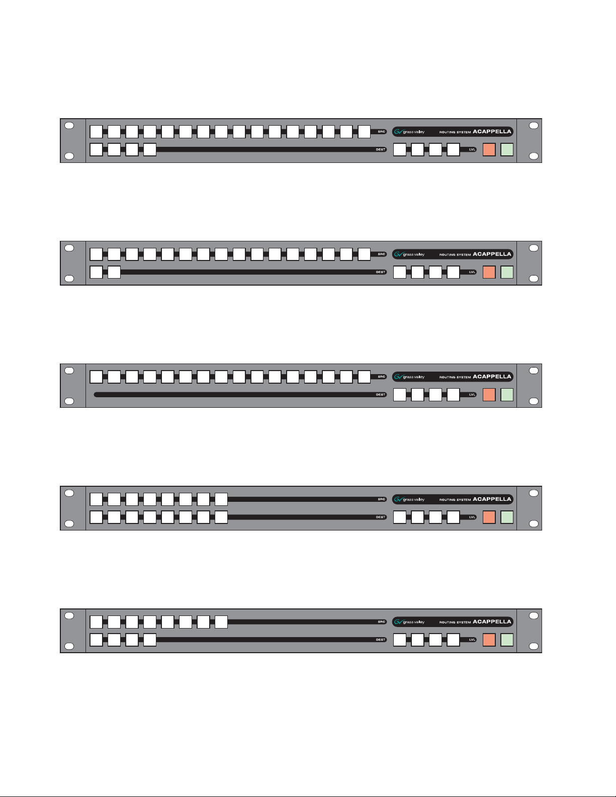
Figure 4 is a panel with 16 Sources and 4 Destinations.
Figure 4. 16x4 Front
Figure 5 is a panel with 16 Sources and 2 Destinations.
Figure 5. 16x2 Front
Figure 6 is a Remote panel with 16 Sources and 1 Destination.
Figure 6. 16x1 Single Destination Front (Remote Panel Only)
Figure 7 is a panel with 8 Sources and 8 Destinations.
Figure 7. 8x8 Front
Figure 8 is a panel with 8 Sources and 4 Destinations.
Figure 8. 8x4 Front
28 Acappella — Instruction Manual
Page 29
Backplanes
8300_00_16r0
8300_00_20
1
16
15
2
14
13
12
11
3
10
9
4
16
15
5
14
13
6
12
11
7
8
7
8
6
5
9
4
3
10
2
1
V
I
D
E
O
Hardware Description
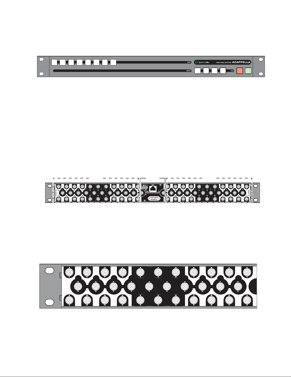
Figure 9 is a Remote panel with 8 Sources and 1 Destination.
Figure 9. 8x1 Single Destination Front (Remote Panel Only)
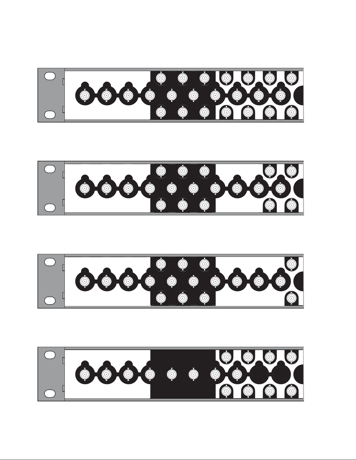
When viewed from the rear, the Acappella backplane is divided as shown
Figure 10. The control area in the center will appear on all frames. The
in
Audio section on the right and the Video section on the left will change
depending upon the configuration of the frame. Inputs are indicated by
white numbers in the black area, are located in the top and bottom row of
the black area, and the entire middle row. Outputs are indicated by black
numbers in the white areas and are located in the top and bottom rows of
the white areas.
Figure 10. Acappella Backplane
Video Audio
Control
Video Configuration (Digital and Analog)
The video BNC backplanes are used with all signal types including High
Definition, Standard Definition, reclocking or non reclocking, and Analog.
The configuration shown in Figure 11 is 16 Inputs by 16 Outputs.
Figure 11. 16x16 Video BNC Backplane
8300_00_34
Acappella — Instruction Manual 29
Page 30
Section 1 — System Overview
8300_00_23
1
16
15
2
14
13
12
11
3
10
9
4
16
15
5
14
13
6
12
11
7
8
7
8
6
5
9
4
3
10
2
1
V
I
D
E
O
8300_00_24
1
16
15
2
14
13
12
11
3
10
9
4
16
15
5
14
13
6
12
11
7
8
7
8
6
5
9
4
3
10
2
1
V
I
D
E
O
8300_00_25
1
16
15
2
14
13
12
11
3
10
9
4
16
15
5
14
13
6
12
11
7
8
7
8
6
5
9
4
3
10
2
1
V
I
D
E
O
8300_00_21
1
2
3
4
5
6
7
8
7
8
6
5
4
3
2
1
V
I
D
E
O
1
16
15
2
14
13
12
11
3
10
9
4
16
15
5
14
13
6
12
11
7
8
7
8
6
5
9
4
3
10
2
1
V
I
D
E
O
The configuration shown in Figure 12 is 16 Inputs by 8 Outputs.
Figure 12. 16x8 Video BNC Backplane
The configuration shown in Figure 13 is 16 Inputs by 4 Outputs.
Figure 13. 16x4 Video BNC Backplane
The configuration shown in Figure 14 is 16 Inputs by 2 Outputs.
Figure 14. 16x2 Video BNC Backplane
The configuration shown in Figure 15 is 8 Inputs by 8 Outputs.
Figure 15. 8x8 Video BNC Backplane
30 Acappella — Instruction Manual
Page 31

Hardware Description
8300_00_22
1
16
15
2
14
13
12
11
3
10
9
4
16
15
5
14
13
6
12
11
7
8
7
8
6
5
9
4
3
10
2
1
V
I
D
E
O
8300 00 35
The configuration shown in Figure 16 is 8 Inputs by 4 Outputs.
Figure 16. 8x4 Video BNC Backplane
The empty configuration shown in Figure 17 is used on systems that have
audio with no video.
Figure 17. Empty Video Backplane
Digital Audio Configuration
The configuration shown in Figure 18 is 16 Inputs by 16 Outputs of single
stream digital (AES) audio.
Figure 18. 16x16 Audio Single Stream BNC Backplane
8300_00_26
Acappella — Instruction Manual 31
Page 32

Section 1 — System Overview
8300_00_27
8300_00_28
8300_00_29
The configuration shown in Figure 19 is 16 Inputs by 8 Outputs of single
stream digital (AES) audio.
Figure 19. 16x8 Audio Single Stream BNC Backplane
The configuration shown in Figure 20 is 16 Inputs by 4 Outputs of single
stream digital (AES) audio.
Figure 20. 16x4 Audio Single Stream BNC Backplane
The configuration shown in Figure 21 is 16 Inputs by 2 Outputs of single
stream digital (AES) audio.
Figure 21. 16x2 Audio Single Stream BNC Backplane
32 Acappella — Instruction Manual
Page 33

Hardware Description
8300_00_36
The configuration shown in Figure 22 is 8 Inputs by 8 Outputs of dual
stream digital (AES) audio.
Figure 22. 8x8 Audio Dual Stream BNC Backplane
The configuration shown in Figure 23 is 8 Inputs by 4 Outputs of dual
stream digital (AES) audio.
Figure 23. 8x4 Audio Dual Stream BNC Backplane
8300_00_328300_00_33
The empty configuration shown in Figure 24 is used on systems that have
video with no audio.
Figure 24. Empty Audio Backplane
Analog Audio Configuration
Analog audio backplanes are equipped with Phoenix connectors that each
carry two balanced audio channels (typically left and right stereo). Inputs
Acappella — Instruction Manual 33
Page 34

Section 1 — System Overview
8300_02_54_r0
8300_02_58_r0
are located on the left, and outputs are located on the right (as viewed from
the rear). Representative analog audio backplanes are shown below.
Figure 25. 16 x 16 Analog Audio
Figure 26. 16 x 4 Analog Audio
Note The bottom row of analog audio connectors are mounted upside down in
relation to the top two rows, due to internal board space limitations. The
removable connectors are wired the same regardless of row used.
Analog frames also offer a Dual Stereo configuration, which divide the
matrix into two groups with independent inputs and outputs. Inputs for
one group can only be routed to outputs of the same group, not to outputs
of the other group. The inputs and outputs of each group are labeled with
a leading number, 1- or 2-. Two Dual Stereo analog configurations are avail
able, one with eight outputs per group Figure 27), and the other with four
outputs per group (Figure 28).
-
34 Acappella — Instruction Manual
Page 35

Figure 27. 8 x 8 Dual Stereo Analog Audio
Figure 28. 8 x 4 Dual Stereo Analog Audio
Hardware Description
8300_02_55_r08300_02_57_r0
Acappella Router and Remote Panel Variations
Acappella routers are available in single and dual formats with a variety of
inputs and outputs. Options include an integral control panel on the front
of the router and redundant power supplies.
number of the Acappella router identifies the configuration of the frame.
Table 2. Acappella Routers Example Model Code
A 16 8 HR- DU- L P
Chassis Options, L= Local control panel
Secondary Signal Format V = Analog video
Primary Signal Format
Number of Outputs: 2, 4, 8, or 16
Number of Inputs: 8 or 16
A = Acappella
P = Internal redundant power supply (digital only)
S = SD video
SR = SD video w/reclocking
HR = HD video w/reclocking
AU = AES audio, unbalanced 75 Ohm BNC
AB = AES audio, balanced 110 Ohm terminals
DU = Dual AES audio, balanced, 110 Ohm terminals
DBT = AES audio, transformer coupled, 110 Ohm terminals
AA = Dual-channel, analog audio, balanced
QA = Dual stereo analog audio
Table 2 shows how the model
Acappella — Instruction Manual 35
Page 36

Section 1 — System Overview
Acappella Remote Control panels are also available in many different configurations (Ta bl e 3).
Table 3. Acappella Remote Control Panels Example Model Code
A 16 1 RCP GPI
GPI Joystick Override
Indicates Remote Control Panel
Number of Outputs: 1, 2, 4, 8, or 16
Number of Inputs: 8 or 16
A = Acappella
A84HR-CLP 8x4 HD Router Clean Switch Limitations
Prelude Configuration
The new Acappella A84HR-CLP matrix type is currently not recognized in
the Prelude routing control system. This means the drag-and-drop method
of configuration cannot be used.
The Prelude Instruction Manual explains how to manually configure and
add a new matrix to a Prelude router configuration. Please follow these
steps with the exception of the choice of matrix type.
Double-clicking on the Matrix-Type cell in the Prelude configuration screen
will bring up a list of available known matrix types allowed to be used for
configuration. Choose the option
options are described in the Prelude Instruction Manual.
Frame Sync Validated for HD Operation
The Frame Sync function is currently proven and tested for use only with
HD input video sources. The frame sync is capable of SD input video oper
ation, but it is not warranted to work properly in the Acappella 2.2.0
release. If the frame sync does not pass SD input video correctly, two work
arounds are available that should fix the problem:
• Change the field rate setting from Use Reference to 59.94Hz or 50Hz on the
Frame Sync web page, depending on the field rate of the video passed
through the Acappella and/or the reference signal attached to it. This
change forces the video detector to work properly.
Acappella HD-R. All other configuration
-
-
• While passing SD video through either output channel 1 or output
channel 2 of the Frame Sync function, ensure an HD or SD video signal
is present on the other Frame Sync channel as well. This forces valid
signals to the timing recovery circuitry when passing SD video.
36 Acappella — Instruction Manual
Page 37

Installation
8103_00_37
44 mm
1.75 in.
432 mm
17 in.
392 mm
15.43 in.
483 mm
19 in.
Measurements do not
include clearance for cables.
Acappella Frame Rack Installation
The Acappella frame is installed in a standard 483 mm (19 inch) rack. The
frame occupies 1 rack unit. Cooling is by horizontal front-to-back airflow.
See
Figure 29.
Figure 29. Acappella Installation Front View
Section 2
Note The depth shown is for the frame. Additional space is needed for cable clear-
Acappella — Instruction Manual 37
ances.
Page 38

Section 2 — Installation
Remote Panel Rack Installation
Remote panel rack mounting is straightforward and requires no special
tools or adaptors. Simply position the Remote Panel in the rack and secure
the panel in place. Refer to
Figure 30. Rack Mount Remote Panel Installation
Figure 30.
44 mm
1.75 in.
106 mm
4.18 in.
483 mm
19 in.
Measurements do not include clearance for cables.
432 mm
17 in.
8300_00_48r0
A rear frame support kit is available as an option (ACAP24RACKKIT).
38 Acappella — Instruction Manual
Page 39

Acappella Cabling
8300_00_04
Video Outputs
1, 3, 5, & 7
Video Outputs
9, 11, 13, & 15
Video Inputs
11, 13, & 15
Video Outputs
2, 4, 6, & 8
Video Outputs
10, 12, 14, & 16
Video Inputs
12, 14, & 16
Audio Outputs
1, 3, 5, & 7
Audio Outputs
9, 11, 13, & 15
Audio Inputs
11, 13, & 15
Audio Outputs
2, 4, 6, & 8
Audio Outputs
10, 12, 14, & 16
Audio Inputs
12, 14, & 16
Video Inputs
1, 2, 3,
4, 5, 6,
7, 8, 9,
& 10
Audio Inputs
1, 2, 3,
4, 5, 6,
7, 8, 9,
& 10
Ethernet
Reference
Loop
Reference Loop
75 ohm Terminator
Redundant
Power Supply
Power
Supply
Serial
RS-422
Figure 31 shows all possible cabling for a 16x16 Acappella frame with 16
Video Inputs and Outputs and 16 single stream AES Audio Inputs and
Outputs using BNC connectors. The second Power Supply is optional.
Figure 31. 16x16 Cabling
Acappella Cabling
Acappella — Instruction Manual 39
Page 40

Section 2 — Installation
8300_00_05
Video Outputs
1, 3, 5, & 7
Video Outputs
2, 4, 6, & 8
Audio Outputs
1-1, 1-3,
1-5, & 1-7
Audio Outputs
2-1, 2-3,
2-5, & 2-7
Audio Outputs
1-2, 1-4,
1-6, & 1-8
Audio Outputs
2-2, 2-4,
2-6, & 2-8
Video Inputs
1, 2, 3,
4, 5, 6,
7, & 8
Audio Inputs
1-1, 1-2,
1-3, 1-4,
1-5, 1-6,
1-7, & 1-8
Audio Inputs
2-1, 2-2,
2-3, 2-4,
2-5, 2-6,
2-7, & 2-8
Reference Loop
75 ohm Terminator
Reference
Loop
Ethernet
Redundant
Power Supply
Power
Supply
Serial
RS-422
Figure 32 shows all possible cabling for an 8x8 Acappella frame with 8
Video Inputs and Outputs and 8 dual stream AES Audio Inputs and
Outputs using BNC connectors. The second Power Supply is optional.
Figure 32. 8x8 Cabling
40 Acappella — Instruction Manual
Page 41

Analog Audio Pinouts
Phoenix style connectors are used for wiring analog audio. Space limitations required the bottom row of connectors be oriented upside down, but
the removable connectors are wired the same regardless of row used.
Figure 33. Analog Audio Backplane
Figure 34. Phoenix Connector Pinouts for Stereo Analog Audio
Top 2 Rows (connector right side up)
Acappella Cabling
8300_02_54_r0
+ - G + - G
A B
+ - G + - G
Ch A (Left)
Ch B (Right)
Bottom Row (same connector upside down)
G - + G - +
B A
Ch A (Left)
Ch B (Right)
8300_02_56_r0
Acappella — Instruction Manual 41
Page 42

Section 2 — Installation
8300_00_38
Reference Loop
75 ohm Terminator
Ethernet
Serial
RS-422
Reference
Loop
Control Cabling
Ta bl e 4 shows the connectors in the Control area of the Acappella frame.
Table 4. Control Cabling
Label
ENET RJ-45 Female Ethernet network communication interface is 100Base-T compatible, use
SERIAL 9 pin D Female RS-422 interface, use serial cable.
REF LOOP BNC Female Video reference supports Color Black or Tri-Level-Sync, use unbalanced 75
Connector
Type Gender
Details
Category 5e cable, 8 conductor twisted pair.
ohm connector, Loop-thru cabling supported.
Serial 9 Pin D Connector Pinout
Ta bl e 5 contains pinout information for the Serial RS-422 9 Pin D connector.
Table 5. Serial D Connector Pinouts
Controlled Pin Function Pin Function
9 Pi
1
5
n D Female
6
9
GND
1
TX-
2
RX+
3
RX Com
4
NC
5
Note Refer to the latest version of the Routing Products Protocols Manual for
information about the Terminal/Computer Interface (T/CI) Protocol used to
control Acappella systems. This manual is available for download on the
Grass Valley web site (see
page 4).
TX Com
6
TX+
7
RX-
8
GND
9
-
-
Ethernet Cabling
The Acappella frame uses Ethernet to communicate. Use standard pin-topin (patch) Category 5e cables if you are using switches between the
routers, panels, and PC. It is also possible to use a crossover cable to
connect an Acappella Router directly to either a Remote Panel or a PC; this
option is only practical in very small systems.
Network system with an Acappella router, a Remote Panel, and a PC connected to a switch.
42 Acappella — Instruction Manual
Figure 35 shows a Closed
Page 43

Figure 35. Ethernet Cabling
8300_01_44
Acappella
Remote Control Panel
Ethernet Switch
PC-compatible
Reference Cabling
Reference signals are loop-thru with the end of the chain terminated. Color
Black or Tri-Level Sync signals are used. The Reference shown in
is the default cabling for plug and play.
Figure 36. Video Reference Connections
Acappella Cabling
Figure 36
Reference Generator
75 ohm
Terminator
See Router Reference Configuration Page on page 88 to select AES Src 1
instead of the Color Black or Tri-Level Sync Reference. Web Page configuration is required
In Figure 37 a Continuous AES Signal is connected to Audio Input 1.
Figure 37. Reference Signal Cabling Option for Single Stream Audio
Reference Generator
75 ohm Terminator
AES Signal
8300_00_50
8300_00_39
Acappella — Instruction Manual 43
Page 44

Section 2 — Installation
8300_00_40
75 ohm
Terminator
Reference Generator
AES Signal
8300_01_42r1
Female Plug Male Plug Female PlugMale Plug
Power SupplyRedundant Power Supply
In Figure 38 a continuous feed AES signal is connected to Audio Input 2-1.
Figure 38. Reference Signal Cabling Option for Dual Stream Audio
Remote Panel Cabling
The Remote Panel has connectors for RJ-45 Ethernet and AC Power. See
Figure 39.
Power
Digital Frames
Figure 39. Remote Panel Cabling
LANAC Power
The Acappella digital frame uses internal auto-ranging AC power supplies.
One Power Supply is standard, the optional second Power Supply is fully
redundant.
The frame ships with one or two captive power cords. A separate power
cord (shipped with the frame) needs to be attached to each of the captive
power cords as shown in
Figure 40
8300_00_07r1
Figure 40. AC Power Supplies
44 Acappella — Instruction Manual
Page 45

A bale clamp is provided to secure the power cords.
Bale
8300_00_43
INPUTS
OUTPUTS
ENET
REF
LOOP
J2
J1
SERIAL
PWRPWRPWRPWR
8300_02_59r0
Female Plug
Female Plug
Male Plug
Male Plug
Power Supply
Redundant Power Supply
Figure 41. Power Cord Bale Clamp
Analog Frames
The Acappella analog frame uses external auto-ranging AC power supplies. The power supplies connect to the rear of the frame (Figure 40).
Figure 42. External Power Supplies
Defaults for Plug and Play
Defaults for Plug and Play
Default Levels are determined by the router’s physical configuration. A
router with a physical configuration of 8x8HR-DU would have 3 default
Levels; Level 1 is HD wideband reclocking serial digital Video, Level 2 is
AES digital Audio 1, Level 3 is AES digital Audio 2.
The default AES digital Audio attributes are; Audio mode: Normal, Resolution:
20 bit
, and Block Align: On. All other AES digital Audio attributes are inactive.
Acappella — Instruction Manual 45
Page 46

Section 2 — Installation
46 Acappella — Instruction Manual
Page 47

Panel Operation
8300_00_52r0
1122334
4
Lvl 1 Lvl 2 Lvl 3 Lvl 4
5566778 9 10 11 12 13 14 15 16
8
EnabProt
Levels
On Indicators
Destinations
Sources
Protect Enable
Local Panels and Remote panels expand the functionality of the Acappella
router.
A frame that has 8 Inputs, 4 Outputs, digital video and Dual Stream digital
AES audio, would have three Levels of 8 inputs and 4 Outputs as follows:
• Eight inputs and four outputs of video,
• Eight inputs and four outputs of audio, and
• A second set of eight inputs and four outputs of audio.
The On Indicators will be lit when there is power to the panel. See Figure 1.
Button illumination will be either Off, Backlit, Low Tally, or High Tally
depending on the button’s status.
Section 3
Enable Button
Enable Button Action
Figure 1. 16x8 Local Panel Layout
The Enable button is green and is found on the lower right of the panel. See
Figure 1.
Press and release of an active Enable button causes the following actions:
• Deactivates the panel,
Acappella — Instruction Manual 47
• Inactive Enable button is illuminated at Backlight Tally, and
•The Protect and Source buttons do not operate.
Page 48

Section 3 — Panel Operation
Protect Button
Press and release of an inactive Enable button causes the following actions:
• Activates the panel, and
• Active Enable button is illuminated at High Tally.
Other button activity on an inactive panel (not enabled):
• Source Tally (on active Destinations) is displayed normally,
• Active Destination can be changed (by press and release of another
Destination button) to view Source status on the new Destination,
• Levels can be changed to view Source status on any Level, and
• A Destination Gang preset can be created, but not Taken.
No change is allowed to the current Source on a protected Destination,
either by action on this panel, or by any remote device (via ethernet) action.
Any device can enable or disable the Destination protection. The
button is red and is found on the lower right of the panel. See
Protect
Figure 1.
Protect Button Action
Press and release of the inactive Protect button to activate a Protect causes
the following actions:
• Active Protect button is illuminated at High Tally,
• Activates Protect status on the active Destinations, and
• All Destinations in a Destination Gang are protected.
Press and release of the active Protect button causes the following actions:
• Inactive Protect button is illuminated at Off Tally,
• Deactivates Protect on the active Destinations, and
• All Destinations in a Destination Gang are removed from the Protected
state.
48 Acappella — Instruction Manual
Page 49

Source Button
Single Source Button Action
Source Button
Press and release of a single Source button causes the following actions:
• Connects a Source to the active Destination on all active Levels,
• Tallys only the active Source at High Tally illumination intensity,
• All other Sources become inactive at Backlight Tally illumination intensity,
If a Breakaway,
• The single Source button is High Tally,
• The left most active Level button is High Tally,
• The Breakaway level is low tally, and
• Inactive Level Tally remains at Backlight intensity,
If Chop function is active (Local Panel),
• Press and release of a Source button inactivates the Chop, and
• Connects the Source to the active Destination,
Note Chop is a toggle between two Sources to a single Destination.
If Destination Gang and All Levels are active (Local Panel),
• Press and release of a Source button connects that Source to all Destinations in the Gang,
•All Destination buttons (in the Gang) are High Tally, and
• Active All Level button Tally is updated to High Tally,
If Destination Gang is active, but not All Levels active (Local Panel),
• Press and release of a Source button connects that Source to all Destinations in the Gang for only the active Levels,
• The individual Destination buttons (in the Gang) are either Low Tally to
indicate Breakaway, or High Tally to indicate no Breakaway, and
•All active Level button Tally is updated to indicate either Breakaway as
Low Tally, or no Breakaway as High Tally.
Note Chop is not available on a Remote Panel. The Chop will only be on the Local
Panel and on the Local Levels output. It will not change the output of the
Remote Levels in the system. However, if any Source is selected by any panel
in the system it will stop the Chop.
Acappella — Instruction Manual 49
Page 50

Section 3 — Panel Operation
Multiple Source Button Action (Local Panel)
Press and release of a Source button while press and hold of the current
Source button causes the following actions:
• Initiates the Chop function between two Sources on a single Destination,
• If Destination Gang is currently active, Chop will not invoke, and
•Both Source buttons are High Tally during active Chop function.
After Chop function is activated, press of any button will inactivate the
Chop.
Note Chop is not available on a Remote Panel. The Chop will only be on the Local
Panel even in systems that have remote levels. However, if any Source is
selected by any panel in the system it will stop the Chop.
Destination Button
Single Destination Button Action
Single Destination button press and release causes the following actions:
• Activates that Destination,
• Inactivates all other Destinations,
• Active Destination button is High Tally,
• Inactive Destination buttons are Backlight Tally,
• Updates the Source Tally and active Level Tally to reflect the active Des-
• Inactive Level Tally remains at Backlight Tally, and
• Destination Gang is cancelled.
Multiple Destination Button Action
tination status,
Press and release of a Destination button while press and hold of active Des-
tination button will create a Destination Gang condition with the following
actions:
• A second press and release of a secondary Destination button (while the
primary
that Destination from the Destination Gang,
50 Acappella — Instruction Manual
Destination button is still depressed) will drop or add (toggle)
Page 51

Level Button
Level Button
• If any Destination is currently Protected, that Destination will not be
added to the Gang,
When a secondary Destination is added to the Destination Gang,
• High Tally if it is connected to the same Source (on all active Levels) as
the primary Destination,
• Low Tally if it is connected to a different Source (on any active Level) as
the primary Destination, and
•All active Level button Tally is updated to indicate either Breakaway as
Low Tally, or no Breakaway as High Tally.
The left most enabled Level button is the Tally Level, it is High Tally and the
Source Tally is updated to be the Source on this Level.
Single Level Button Action
Press and release of a disabled Level button causes the following actions:
• Activates the Level,
• High Tally if the Source connected on that Level is the same Source as
the left most Tally Level button,
• Low Tally if the Source connected on that Level is not the same Source
as the left most Tally Level button
Press and release of enabled Level button causes the following actions:
• Inactivates that Level, and
• Level button is Backlight Tally.
Acappella — Instruction Manual 51
Page 52

Section 3 — Panel Operation
Video Destination
Audio Destination
DVTR 3
Video Source B (VSB)
Audio Source B (ASB)
DVTR 2
Video Source A (VSA)
Audio Source A (ASA)
DVTR 1
Acappella
Video
Audio
VSB
ASB ASB
8300_00_45
ASA
ASA ASA
VSA
VSAVSA
Video Destination
Audio Destination
DVTR 3
Video Source B (VSB)
Audio Source B (ASB)
DVTR 2
Video Source A (VSA)
Audio Source A (ASA)
DVTR 1
Acappella
Video
Audio
VSA
VSA
ASA
VSA
ASA
VSB
ASB ASB
8300_00_46
ASB
Multi-Level Switching
There are two modes of multi-Level switching: All-Level Takes and Breakaway Takes. All-Level Takes switch the same input number on all Levels,
to the controlled Destination, as shown in
Figure 2. Traditional All-Level Take
Figure 2.
A Breakaway Take is performed by accessing the control Levels of a Destination individually and selecting a different Source on at least one Level
other than that selected on the others. Breakaways allow a Destination to
selectively utilize video and audio from different Sources.
Figure 3. Breakaway Take
52 Acappella — Instruction Manual
Page 53

Section 4
Software and Configuration
Network Configuration
PC Requirements
A customer supplied PC is used for software installation and initial system
configuration. This PC must meet the following minimum requirements:
• 256 Mb RAM,
• 10 Mb available hard disk space,
• 100BaseT Ethernet Network Interface Card,
• Monitor with a screen resolution of 1024 x 768,
• Windows XP SP2 and above operating system,
• Logged in with Administrator-level privileges for the local machine,
and
• Internet Explorer version 6.0 or later.
PC Network Configuration
The PC you will use must be configured to operate on the Acappella standalone network. This is accomplished by setting the IP address of the PC to
be compatible with the IP addresses of the Acappella system components.
In general, the first three octets of the IP address must be the same, and the
last IP address octet must be unique for each device on the network.
See Tab le 1 on page 54 for a recommended IP address for your PC that will
work with an Acappella system using default network settings.
The exact method used to change the IP address of a PC varies, depending
on the computer’s operating system. Before changing the PC’s IP address
you should note down the existing values so you can easily reconfigure the
computer back to normal operation when finished using it with Acappella.
Acappella — Instruction Manual 53
Page 54

Section 4 — Software and Configuration
Default System IP Addresses
Acappella systems ship with default IP addresses shown in Tab le 1.
Table 1. Acappella System Default IP Addresses
Device IP Address Subnet Mask Gateway
Acappella Matrix Frame 192.168.0.40 255.255.255.0 192.168.0.1
Acappella Remote Panel 192.168.0.41 255.255.255.0 192.168.0.1
User Provided PC
(recommended setting)
These defaults will need to be changed, especially if your Acappella system
has multiple frames and/or multiple remote panels. See
Addresses on page 60 for specific instructions.
CAUTION Encore and Prelude control systems employ consecutive IP addresses for
redundant matrix controller operation. Even though Acappella frames do not
support matrix controller redundancy, if they reside on an Encore or Prelude
network, the next higher IP address must be reserved and cannot be assigned
to another device on the network. Serious system communications problems
can occur if this next higher Acappella frame IP address is used on an Encore
or Prelude network.
192.168.0.1 255.255.255.0 192.168.0.1
Setting IP
Software
Software Installation
Acappella ships with a software CD. Several applications on the CD enable
you to make adjustments to the Acappella configuration. After you have
added a PC to the Acappella network, you need to install the Acappella
software on the PC.
The Acappella Software CD will install the Acappella Matrix software,
Acappella Remote Panel software, NetConfig application (a Network Con
figuration Tool), NetConfig Instruction Manual, and the Acappella Instruction Manual on a PC.
1. Insert Acappella Software CD, it will autostart. If the CD does not start
look for the Setup.exe file.
-
54 Acappella — Instruction Manual
Page 55

2. Click Next when the Welcome screen appears.
Figure 4. Welcome Window
3. Select I Agree, then click Next.
Software
Figure 5. License Windows
Acappella — Instruction Manual 55
Page 56

Section 4 — Software and Configuration
4. Click Next to accept the default directory or Browse to select a different
location for the directory.
Figure 6. Directory Window
5. Click Next to accept all the applications or deselect any applications you
don’t want and then click
Figure 7. Applications Window
Next.
56 Acappella — Instruction Manual
Page 57

Software
6. Click Yes to backup current files. This only applies to upgrading or
reinstalling the software.
Figure 8. Start Installation Window
7. Click Next to begin the Installation.
Figure 9. Start Installation Window
Acappella — Instruction Manual 57
Page 58
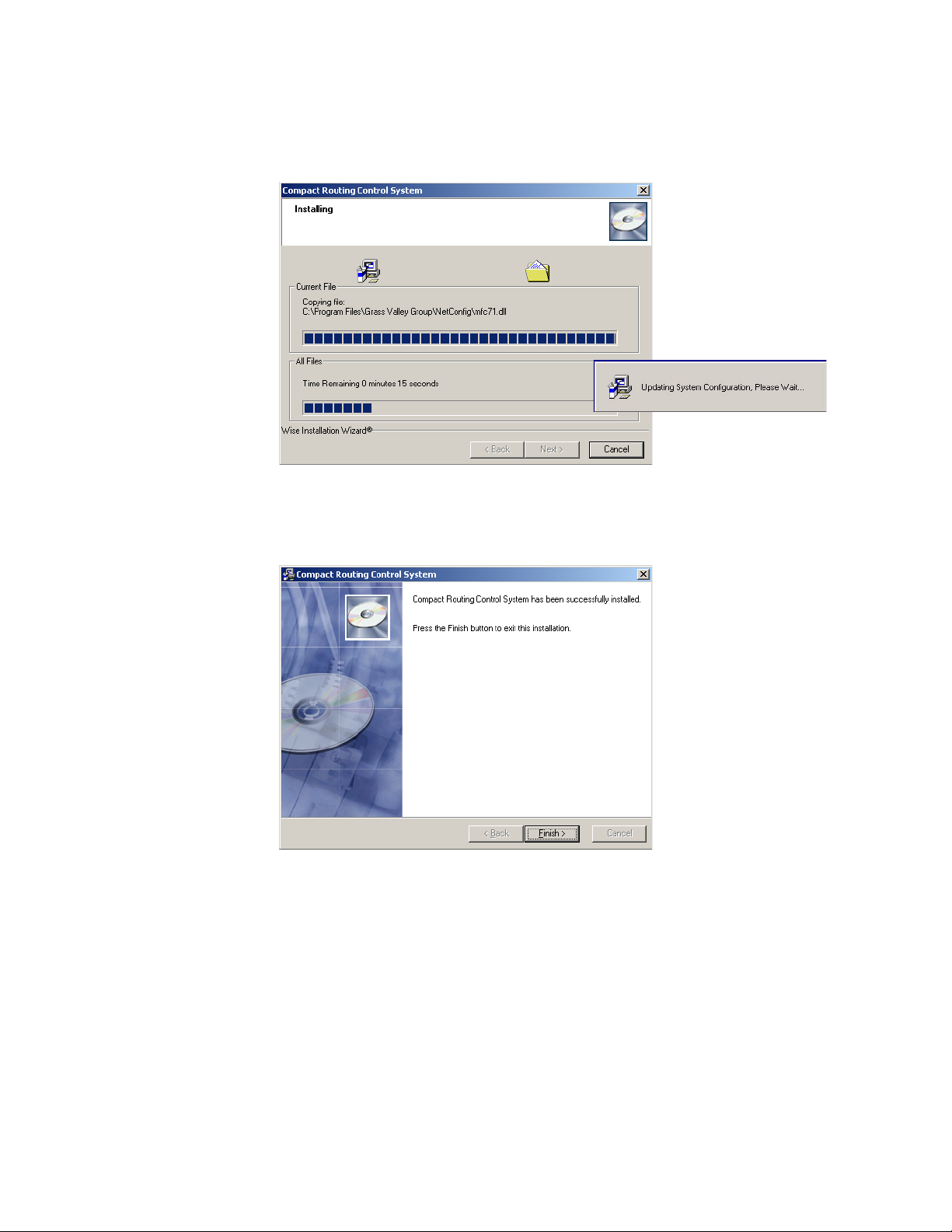
Section 4 — Software and Configuration
Status windows will appear while the software is loading.
Figure 10. Status Windows
8. Click Finish to complete the Installation.
NetConfig
Figure 11. Finish Window
The NetConfig application is designed to make network configuration
simple. NetConfig discovers devices on the network, and these devices can
be configured remotely using the PC on which NetConfig has been
installed. NetConfig incorporates a web browser that displays web pages
served by the devices on the network. NetConfig is also used for software
installation to these devices.
58 Acappella — Instruction Manual
Page 59

NetConfig
Acappella routers are shipped with the NetConfig client installed as are
many other Grass Valley products. Once the NetConfig software is
installed on a PC, you will be able to view and interact with all the Net
Config client devices on the same network.
To open NetConfig find the shortcut on the PC’s desktop.
The left side of the NetConfig application screen displays the logical tree of
the devices on the network. The root of the logical tree is the name and the
IP address of the PC on which NetConfig is running. The current status of
each discovered device is reported by the color of its icon. A red dot, for
example, indicates a device is no longer communicating, which might
mean it has been disconnected from the network.
The right portion of the screen is the web browser view. When you click a
device on the left, the home page for that device is displayed in the web
browser view on the right.
In a closed network, Acappella and an Acappella Remote panel would
appear as shown in
Figure 12.
-
Figure 12. NetConfig Window
Select the device that you want to view from either the IP View or the
Device View. See
Acappella — Instruction Manual 59
Acappella Configuration Pages on page 66 for details.
Page 60

Section 4 — Software and Configuration
NetConfig Manual
A NetConfig manual .pdf file is installed onto the PC along with the NetConfig application. The manual is located in a Documentation subdirectory
in the NetConfig directory.
Setting IP Addresses
In most cases, Acappella IPs need to be changed to match your facility’s
network requirements. Acappella system default IP addresses must be
changed, especially when the system has more than one Acappella router
and/or more than one Remote Panel, since the same device types ship with
the same IP addresses (see
CAUTION Encore and Prelude control systems employ consecutive IP addresses for
redundant matrix controller operation. Even though Acappella frames do not
support matrix controller redundancy, if they reside on an Encore or Prelude
network, the next higher IP address must reserved and cannot be assigned
to another device on the network. Serious system communications problems
can occur if this next higher Acappella frame IP address is used on an Encore
or Prelude network.
Default System IP Addresses on page 54).
Resolving duplicate IP addresses is easily accomplished with NetConfig. If
a device is installed on the network with the same IP address as another
device, when the new device is discovered a warning message will be dis
played. The IP View will also show the two devices with the same address
with an IP symbol as shown in
with factory default IP addresses are installed on the network.
Figure 13. This can occur if new devices
-
60 Acappella — Instruction Manual
Page 61

Figure 13. Devices with Duplicate IP Addresses
Set IP button
NetConfig
To Resolve Duplicate IP addresses:
1. Select the NetConfig Set IP icon on the toolbar or the Device IP
Addresses in the Configure pull-down.
Figure 14. Set IP
Acappella — Instruction Manual 61
Page 62
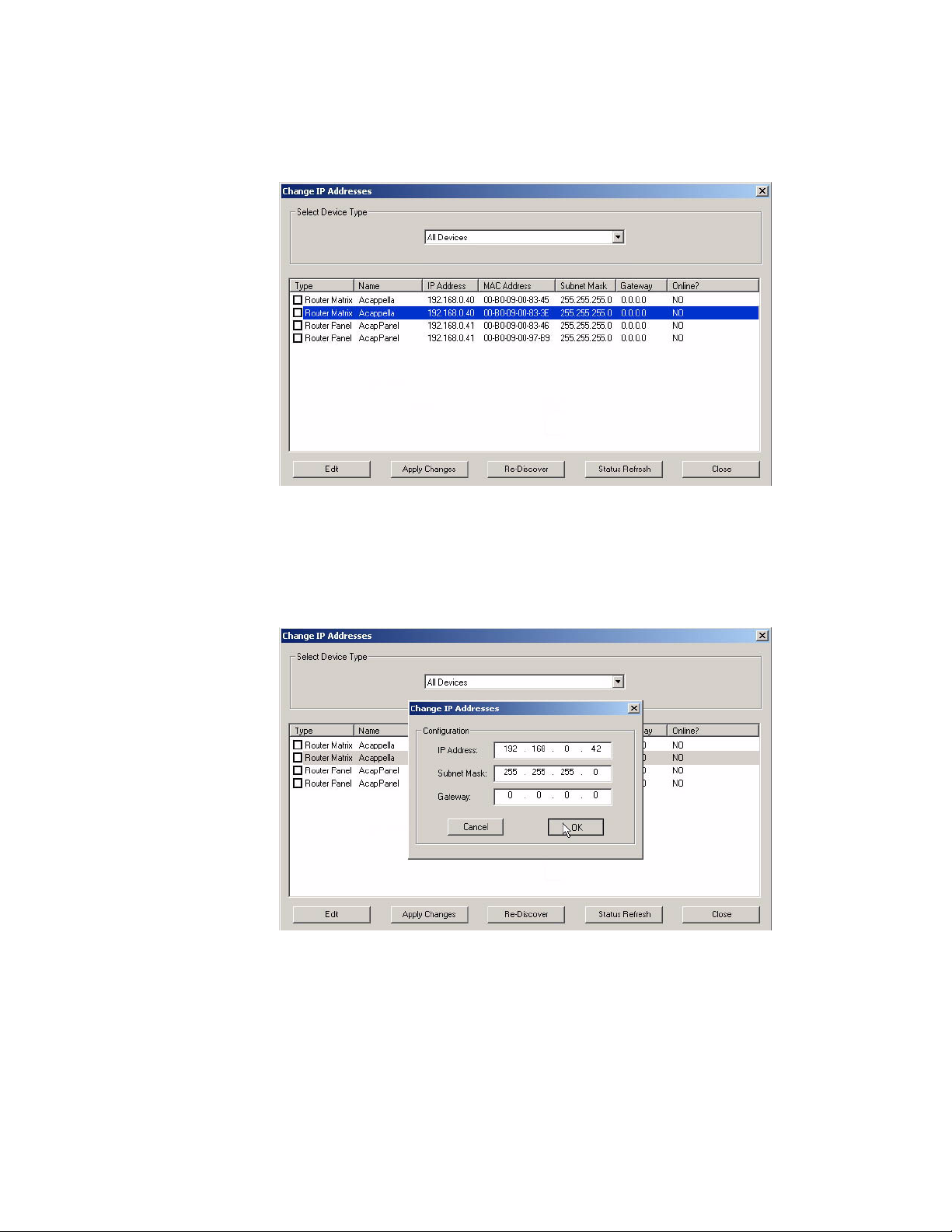
Section 4 — Software and Configuration
2. Highlight one of the devices with a duplicate IP address.
Figure 15. Duplicate IP
3. Click Edit, then change the last octet of at device’s IP address to be
unique. The first three octets of all the IP addresses must be identical,
so all the devices are on the same network.
Figure 16. Change IP
62 Acappella — Instruction Manual
Page 63

NetConfig
Load SW button
4. Click Apply Changes. The device resets, and the new IP address will be
reported in the left pane of NetConfig screen.
Figure 17. New IP Address
When all devices have unique IP addresses, it can be extremely helpful to
label each device with its currently assigned IP address. Sticky labels that
can be removed are advisable, since the IP address may be changed in the
future. To identify a specific remote panel when several are connected at
once, send a reset command to a panel and see which front panel buttons
go off and back on.
Load Software
Use NetConfig to load software to Acappella routers and Acappella
Remote Panels.
1. Open NetConfig and select the Load SW button in the toolbar.
Figure 18. Load SW
Acappella — Instruction Manual 63
Page 64

Section 4 — Software and Configuration
2. The Load Software window will open with Router displayed. Navigate
through the folders to view the latest versions of Acappella panel and
matrix software available for loading, as shown in
Figure 19. Update Devices Window
Figure 19.
3. Highlight Acappella Matrix for Acappella matrices. Matrices will appear
in the right pane of the window, see
Figure 20. Acappella Matrix
4. Check the box for the Acappella to update in the Client Name list.
5. Check the Re-Boot when complete checkbox in the lower lefthand corner to
have the matrix re-boot when the software update is complete.
Figure 20.
6. Click the Load button to begin the update.
7. Once all matrix downloads are complete, use the Refresh button to
update the window and check that the version of software has been
downloaded to each selected device successfully.
64 Acappella — Instruction Manual
Page 65

Web Browser Interface
8. Highlight Acappella Panel bin for Remote Panels. The Remote Panels on
the network will appear in the right pane of the window, see
Figure 21. Remote Panels
9. Check the box for the Acappella Remote Panel to update in the Client
Name
list.
Figure 21.
Web Browser Interface
10. Check the Re-Boot when complete checkbox in the lower left corner to have
the panel(s) re-boot when the software update is complete.
11. Click the Load button to begin the update.
12. Once all Panel downloads are complete, use the Refresh button to
update the window and check that the version of software has been
downloaded to each selected device successfully.
13. When finished, select the Close button.
Enter the IP address set for the Acappella matrix frame or Remote panel
into a web browser to access the Acappella configuration pages. If you
don’t know what these IP addresses are, you can use NetConfig to see the
IP Addresses of all the devices on that network.
Acappella — Instruction Manual 65
Page 66

Section 4 — Software and Configuration
Refresh Button
Acappella Configuration Pages
Router Configuration
Acappella routers use a set of web pages to provide information and to
allow user defined configuration changes. The pages are accessed by either
NetConfig or a web browser.
Router Status Page
The Router Status page is a read only page. Some of the information displayed here is entered automatically such as Product Part Number, Serial
Number, etc. The Location and Asset Tag can be changed on a different
page. The Level, Source (SRC), and Destination (DST), Crosspoint status
will reflect the current state of the router when the page was accessed. To
update the Crosspoint information click on the
Refresh button.
Figure 22. Router Status Page
Refresh Button
An refresh button icon located at the top of this and other Acappella web
pages updates the web page with the latest information (
66 Acappella — Instruction Manual
Figure 22).
Page 67
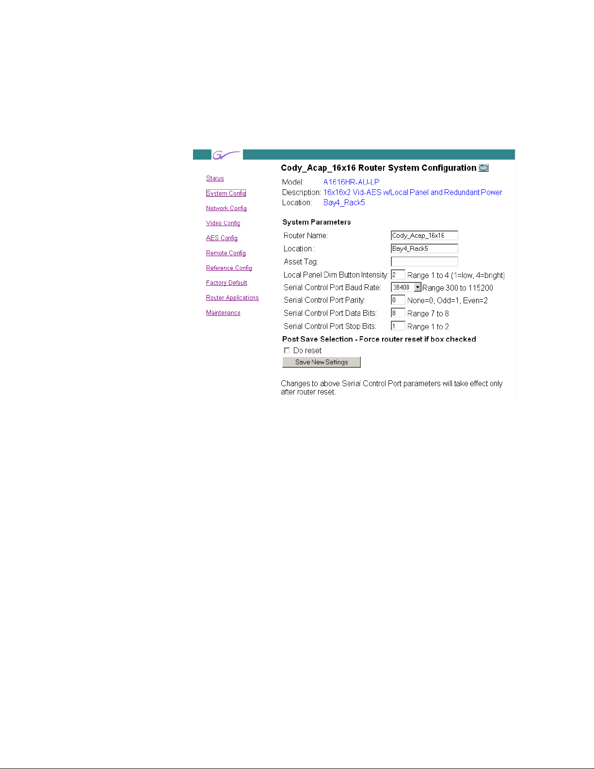
Router System Configuration Page
The Router System Configuration page is used to make adjustments to the
router system parameters.
Figure 23. Router System Configuration Page
Acappella Configuration Pages
The first three user configuration items are optional and can be left blank:
Router Name:
This field is used to give the router a unique name. The name entered here
will appear at the top of each of the router web pages. The name will also
appear in the NetConfig logical tree list under
field will accept up to 60 characters. However, it is recommended that
entries be kept short to keep the name from wrapping.
IP View and Device View. The
Location:
This field is used to give the router a physical location name. The location
entered here will appear in the header for each of the router web pages. The
field will accept up to 60 characters. However, it is recommended that
entries be kept short to keep the name from wrapping.
Asset Tag:
This field is used to track internal capital asset numbers that a user might
assign to a router. The field will accept up to 20 characters.
Acappella — Instruction Manual 67
Page 68

Section 4 — Software and Configuration
The following two settings come from the factory with default settings.
User adjustments can be made to these settings. The default settings can be
restored on the
Local Panel Dim Button Intensity:
This setting is used to adjust the button brightness at Low Tally.
Serial Control Port Baud Rate:, Parity:, Data Bits:, and Stop Bits:
These settings are used for serial interface settings for the 9 pin D connector
on the router. These settings are configured according to the requirements
of the controlling serial device.
The following two controls are used to change the settings:
Do reset
When checked, the router will be reset when the Save New Settings button is
clicked.
Router Factory Defaults Page page.
Save New Settings
This button saves changes to the Router Name, Location, Asset Tag, and Local
Panel Dim Button Intensity
To view changes after clicking the Save New Settings button, click on the
Refresh button.
fields.
68 Acappella — Instruction Manual
Page 69

Router Network Configuration Page
Router Network Configuration page is used to change the IP Address,
SubNet Mask, and Gateway IP Address, of the router.
Figure 24. Router Network Configuration Page
Acappella Configuration Pages
Setting IP Addresses with Web Page
CAUTION If there is more than one panel or frame in a system, duplicate IP addresses
may exist. To resolve duplicate IP Addresses see
page 60.
The IP addresses of the device can be set directly from its web page by
entering the new numbers in the
fields.
You will need to check Do reset and Save New Settings before the change will
take effect.
Ethernet IP:, Subnet Mask: and Gateway IP:
Setting IP Addresses on
System Identifier:
Leave this setting to Default on an Acappella system running on its own network.
If your Acappella system is running on a network shared by Prelude or
Encore systems, you can isolate them from one another by assigning dif
ferent ports for each system. The easiest way to do this is to assign one of
the System Identifier buttons (Default, 1 - 5) to all the components of the
first system, and then assign a different button to all the components of the
-
Acappella — Instruction Manual 69
Page 70

Section 4 — Software and Configuration
next system. The Matrix Control Port Number reports the actual port that will be
used by the device. For example, if you wish to run an Acappella system on
the same network as an Encore system, you can choose button
for the Acappella frame and all the Acappella panels. The Encore system
can continue to use the default port setting (6050).
Note All components on an individual system must use the same System Identifier
(port) number.
Alternatively, you can assign a specific port n umber to a device by choos ing
Manual Select, which opens a text entry field. This feature is intended only
for qualified system administrators experienced with network configura
tion.
System Broadcast Select:
Leave this setting at Use Broadcast if your Acappella system has none or only
a small number of remote panels (three or less).
Selecting Use Multicast makes this Acappella device employ a more efficient
networking mechanism, useful for systems with several remote panels.
1 (port 6051)
-
Note All components on an individual system must use the same Broadcast set-
tings.
70 Acappella — Instruction Manual
Page 71

Acappella Configuration Pages
Table 2. Rates
143Mb/s SD or Wideband
270 Mb/s SD or Wideband
360 Mb/s SD or Wideband
540 Mb/s SD or Wideband
1.485 Gb/s HD only
Bypass Non-reclocking
Auto Reclocking
Router Video Configuration Page (Non Frame Sync)
The Router Video Configuration page is used to set parameters on a Destination by Destination basis. This web page on Non Frame Sync Acappella
systems is similar to
Figure 25. Router Video Configuration Page
Figure 25.
Note Analog Video Acappella systems do not display a Video Configuration Page
because there are no user adjustments of the analog video.
On Digital Video systems, the Router Video Configuration Page will not
appear unless the Acappella router has a video level.
The default setting is Auto.
Auto reclocking will lock to a signal rate of either 143 Mb/s, 270 Mb/s, 360
Mb/s, 540 Mb/s, or 1.485 Gb/s (1.485 Gb/s is HD Wideband).
Bypass will pass the signal without reclocking.
Selecting a signal rate such as 270 Mb/s will cause the Output to lock to the
selected signal rate. If the incoming signal is not the selected rate the
Output will be put into Bypass mode. For example, if the incoming signal
is 1.485 Gb/s and the reclocking rate selected is 540 Mb/s which is incor
-
Acappella — Instruction Manual 71
Page 72

Section 4 — Software and Configuration
rect, then the signal would be in Bypass with no reclocking and the Output
would report Not Locked.
After selecting a new reclocking rate, the router will try to lock the Output
to that rate. It may take several seconds and clicking the
see the change.
such as 270 Mb/s is selected as the Reclocking Rate then the Output would
show
270 Mb/s.
Refresh button to
Figure 25 shows Bypass and Auto settings. If a signal rate
72 Acappella — Instruction Manual
Page 73

Acappella Configuration Pages
Router Video Configuration Page (With Frame Sync)
The A84HR-CLP 8x4 HD Router with Clean Switch Acappella hardware
has a Router Video Configuration page similar to
Destinations DST 1 and DST 2 are read-only fields and reported as
Auto (Default) and the Output column is reporting the present video format
detected on this output. The Frame Sync column will report if the FS-1
function is
Video Frame Sync Configuration web page (
Note Frame Sync FS-2 is not active at this time.
Figure 26. .Acappella Video Config Web Page
Present or Not Present. All of this information comes from the
Figure 27 on page 75).
Figure 26.
Select the Configure button in the Frame Sync column (or use the Frame Sync
link under the Video Config link on the left) to access the Video Frame Sync
Configuration web page (see
page 74).
Acappella — Instruction Manual 73
Page 74

Section 4 — Software and Configuration
Video Frame Sync Configuration Web Page (Frame Sync Systems Only)
The Video Frame Sync Configuration web page is shown in Figure 27 on
page 75. Use the instructions below to configure the parameters available
on this page. The Output 1 and Output 2 controls are identical in operation.
Output Rate
The Output Rate control allows you to select from three radio button
choices:
• Use Reference – selecting this choice sets the router to use the external reference connected to the Acappella REF LOOP for the timing reference
for Output 1 and Output 2. The reference input standard is reported on
the Router Reference Configuration web page.
• 59.94Hz – select this setting when you want to use the internally generated test signal at a 59.94Hz frame rate.
• 50Hz – select this setting when you want to use the internally generated
test signal at a 50Hz frame rate.
Video Format
Note Before selecting your video format, make sure the frame reference input is
connected and recognized by the router (see
ration Page on page 88).
The video format control provides a pulldown menu to select from one of
the following:
• AUTO (default) – the video format is automatically detected by the router.
• SD – the video format is forced by the module to be SD video (serial digital).
• 720p – the video format is forced by the module to be 720p video (high
definition).
• 1080i – the video format is forced by the module to be 1080i video (high
definition).
Note When forcing the video to a specific format make sure the reference source
fed to the router is compatible with this format.
Router Reference Configu-
74 Acappella — Instruction Manual
Page 75

Figure 27. Router Video Frame Sync Configuration Web Page
Acappella Configuration Pages
Acappella — Instruction Manual 75
Page 76

Section 4 — Software and Configuration
Test Signal Output
One of two internally generated test signal outputs may be placed on the
output with this control for troubleshooting and other purposes. The
Output Rate of the test signal must be set as 59.94Hz or 50Hz with the
Output Rate control (see
The Test Signal Output choices are as follows:
• None – no test signal placed on the output.
• Color Bars – a 75% color bars test signal will be placed on the output at
the frame rate selected in the Output Rate control.
• Blue Screen – a 75% blue screen test signal will be placed on the output
at the frame rate selected in the Output Rate control.
Loss of Signal
The action of the output signal on loss of sign al or sync can be selected from
one of the following:
• Freeze – the output video will freeze on the last good video frame.
Output Rate on page 74).
• Pass – when sync is lost on the input signal, the signal will continue to
be passed to the output.
• Blue Screen – upon loss of signal the output video will freeze on the last
good frame and display it for one second after which a 75% blue screen
will be displayed.
Manual Freeze
A Manual free ze can be performed by the user at any time with this control.
Select one of the following to do a manual freeze:
• None – no manual freeze.
• Frame – freezes the last full frame of video (goes between Field 1 and
Field 2). This is the best choice for a progressive video signal (720p).
• Field – the recommended setting for a moving interlaced (1080i) video
freeze. Provides a cleaner image as it is not switching between fields.
Note The Field radio button will be greyed out when a progressive HD signal is
present.
Audio V-Fade
When this control is enabled, embedded audio present on the Output 1 and
Output
video inputs eliminating any pops or clicks in the audio.
76 Acappella — Instruction Manual
2 video signals will be muted during a switch between the two
Page 77

Acappella Configuration Pages
Vertical and Horizontal Offsets
These controls allow you to adjust the vertical and horizontal offset of the
frame sync reference outputs independently. The adjustment parameters
for each control are given on the web page for each video format.
Before setting these controls it is important to understand that there is a
relationship between these Frame Sync offset controls and the offset con
trols on the Router Reference Configuration web page.
The Vertical and Horizontal Offset controls on the Video Frame Sync Configuration web page have a range of zero to one frame minus one pixel.
Depending on the position of the input video with respect to the reference
frame start, this offset will cause the electrical delay through the frame sync
to wrap around at 2 frames minus 5 lines. The full range of delay control is
from one frame minus 5 lines to 2 frames minus 5 lines. With the input
video aligned with the reference frame start, and zero frame sync offset, the
nominal electrical delay thought the sync is one frame period.
-
Acappella — Instruction Manual 77
Page 78

Section 4 — Software and Configuration
Router AES Configuration Page
Note Analog Audio Acappella systems do not display an AES Configuration Page.
Figure 28. Router AES Output Configuration Page
Several digital audio attributes may be assigned. The defaults are Resolution 20 bit, Audio Mode Normal (Stereo) and Block Align On.
Resolution:
This attribute determines how the signal bits are processed. A signal has 24
bits with the last four bits designated as auxiliary (AUX) bits.
In 20 bit mode the four AUX bits pass through the router unaffected by any
processing. If channels A and B are swapped, the four AUX bits stay in the
same place. If the signal is muted, the four AUX bits are not muted.
In 24 bit mode the router will treat the four AUX bits as though they are part
of the audio data. If Channels A and B are swapped, the four AUX bits will
swap locations. If the audio is muted, the four AUX bits will be muted.
78 Acappella — Instruction Manual
Page 79

Acappella Configuration Pages
The Bypass is setting is used to pass an asynchronous signal. Placing a Destination signal into Bypass mode makes the other settings in the table disappear. Unchecking the Bypass setting returns the last saved settings.
Figure 29. Bypass Mode
Audio Mode
There are four variations in this mode:
• Normal Channel A to Channel A and Channel B to Channel B,
• Swap Channel A to Channel B and Channel B to Channel A,
• A Only Channel A to Channel A and to Channel B, and
• B Only Channel B to Channel A and to Channel B.
Only one of the four variations can be active.
Invert
When a channel is inverted a - (minus sign) will appear in front of the
A or B in the Output column.
Sum
When the channels are summed both an A and a B will appear in the
Output column. A + (plus sign) will appear between the two letters
unless the channels are inverted.
Mute
This attribute creates digital silence. Mute overrides all other settings.
Removing a
lacking a signal is selected, the router will internally generate a syn
chronous silence signal to keep downstream equipment locked.
Mute restores the previously applied settings. If a Source
AES Attributes Reference
The AES Attributes are illustrated here for general reference. Acappella
uses Channel A for Channel 1 or Left, and Channel B for Channel 2 or
Right.
-
Acappella — Instruction Manual 79
Page 80
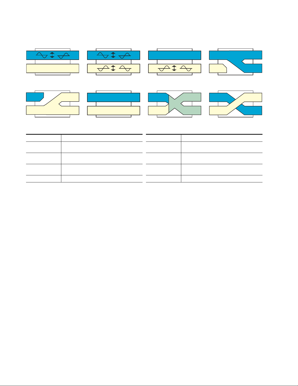
Section 4 — Software and Configuration
CH1
CH1
CH2 CH2
Stereo
Left Channel
Right Channel
CH1
CH1
CH2 CH2
Invert Left
Right Channel
CH1
CH2
Left Mono
Right
Left CH1
CH2Left
CH1
CH2
Right Mono
Right
Left CH1
CH2
Right
CH1
CH1
CH2 CH2
Invert Left & Right
CH1
CH1
CH2 CH2
Invert Right
Left Channel
CH1
CH2CH2
CH1
Swap
Right
RightLeft
Left
CH1
CH2
Sum
Right
Left CH1
CH2
Left & Right
Left & Right
8053_00_09_r0
Figure 30. AES Attributes
Table 3. AES Attributes
AES Attribute Description AES Attribute Description
Invert Left Inverts Left (Channel 1) only. Right (Channel 2) is not
affected.
Invert Right Inverts Right (Channel 2) only. Left (Channel 1) is not
affected.
Right Mono Right (Channel 2) is sent to both Channel 1 and
Channel 2.
Sum Left (Channel 1) and Right (Channel 2) are combined. Swap Left (Channel 1) and Right (Channel 2) are swapped.
Invert Left & Right Inverts Left (Channel 1) and Right (Channel 2).
Left Mono Left (Channel 1) is sent to both Channel 1 and Chan-
nel 2.
Stereo Neither Left (Channel 1) nor Right (Channel 2) is
affected.
80 Acappella — Instruction Manual
Page 81

Figure 31. AES Attribute Combinations
Invert Right - Right Mono
CH1
CH2
Right
Invert Left -Left Mono
Left
CH1
CH2
Invert Left - Sum
CH1
CH2
Left &
Right
Invert Right - Sum
CH1
CH2
Left &
Right
CH2
CH1
Invert Left - Swap
CH2
CH1
Invert Right - Swap
CH1
CH2
Right
Left
CH1
CH2
Right
Left
CH1
CH2
Right
Left
CH1
CH2
Right
Left
CH1
CH2
Right
Left
CH2
CH1
Invert Left & Right - Swap
CH1
CH2
Right
Left
Invert Left & Right - Sum
CH1
CH2
Left &
Right
CH1
CH2
Right
Left
Invert Left & Right - Right Mono
CH1
CH2
Right
CH1
CH2
Right
Left
CH1
CH2
Invert Left & Right - Left Mono
Right
Left
CH1
CH2
Left
CH1
CH2
Right
Left
8053_00_10_r0
Acappella Configuration Pages
AES Attribute Combination Description
Invert Left & Right - Left Mono Inverts Left (Channel 1) and Right (Channel 2) then Left (Channel 1) is sent to both Channel 1 and Channel 2.
Invert Left & Right - Right Mono Inverts Left (Channel 1) and Right (Channel 2) then Right (Channel 2) is sent to both Channel 1 and Channel 2.
Invert Left & Right - Sum Inverts Left (Channel 1) and Right (Channel 2) then Left (Channel 1) and Right (Channel 2) are combined.
Invert Left & Right - Swap Inverts Left (Channel 1) and Right (Channel 2) then Left (Channel 1) and Right (Channel 2) are swapped.
Invert Left - Left Mono Inverts Left (Channel 1) no effect on Right (Channel 2) then Left (Channel 1) is sent to both Channel 1 and Channel 2.
Invert Left - Sum Inverts Left (Channel 1) no effect on Right (Channel 2) then Left (Channel 1) and Right (Channel 2) are combined.
Invert Left - Swap Inverts Left (Channel 1) no effect on Right (Channel 2) then Left (Channel 1) and Right (Channel 2) are swapped.
Invert Right - Right Mono Inverts Right (Channel 2) no effect on Left (Channel 1) then Right (Channel 2) is sent to both Channel 1 and Channel 2.
Invert Right - Sum Inverts Right (Channel 2) no effect on Left (Channel 1) then Left (Channel 1) and Right (Channel 2) are combined.
Invert Right - Swap Inverts Right (Channel 2) no effect on Left (Channel 1) then Left (Channel 1) and Right (Channel 2) are swapped.
Table 4. AES Attribute Combinations
Acappella — Instruction Manual 81
Page 82

Section 4 — Software and Configuration
Router Remote Configuration Page
The Remote Configuration page allows you to create systems using more
than one frame.
Figure 32. Local Frame with Remote Configuration Disabled
The example screens in Figure 33 and Figure 34 show two frames creating
a four Level system. Figure 33 shows a frame that has a single Wideband
HD reclocking 8x8 Level. By combining this frame with another frame that
has a single Wideband HD reclocking 8x8 Level, and two Digital Audio
AES 8x8 Levels (
Levels of Video and two Levels of Audio.
Figure 33. Single Level Local Frame with Three Remote Levels
Figure 34), you have created a four Level system with two
82 Acappella — Instruction Manual
Page 83

Acappella Configuration Pages
The order of levels in the configuration of the two frames must match. If the
single Level frame is configured as Level 1, it has to be Level 1 on all frames
in the system. You can create systems with up to 4 Levels. To change the
order of the Levels use the Move column radio buttons.
Figure 34. Three Level Local Frame with One Remote Level
Create a Four Level HD Wideband System
This example uses four separate frames of 16x16 SD Digital Video to create
a four level system.
1. Select first frame, enable 3 remote Levels on the Remote Config Web
page.
Acappella — Instruction Manual 83
Page 84

Section 4 — Software and Configuration
2. Verify IP Addresses and Type are correct for remote Levels, select Save
New Matrix Config and Reset Router
Figure 35. First Frame Level 1
.
3. Select second frame, enable 3 remote Levels.
84 Acappella — Instruction Manual
Page 85

Acappella Configuration Pages
4. Use Down to move the Level to it proper place as Level 2.
Note To move Levels always use the Up and Down buttons, never try to reorder
Levels using IP Addresses.
Figure 36. Second Frame Level 2 Move Down
Figure 37. Second Frame Level 2
5. Verify IP Addresses and Type are correct for remote Levels, select Save
New Matrix Config and Reset Router
Acappella — Instruction Manual 85
.
Page 86

Section 4 — Software and Configuration
6. Select third frame, enable 3 remote Levels.
Figure 38. Third Frame Level 3
7. Use Down to move the Level to it proper place as Level 3.
Figure 39. Third Frame Level 3 Move Down
8. Verify IP Addresses and Type are correct for remote Levels, if not
change, then select
86 Acappella — Instruction Manual
Save New Matrix Config and Reset Router.
Page 87

Figure 40. Third Frame Level 3 After Move Down
Acappella Configuration Pages
9. Select the fourth frame, enable three remote levels on the Remote
Configuration page, order the levels to match the other three frames in
the system, with frame four as Level 4.
Acappella — Instruction Manual 87
Page 88

Section 4 — Software and Configuration
Minus 1
Minus 10
Plus 1
Plus 10
Save
Minus to Minimum Plus to Max.
Router Reference Configuration Page
Router Reference Configuration Page is used to make adjustments to the
reference signal when the signal is out of zero time with the Source signals.
Figure 41. Router Reference Configuration Page
The video reference adjustments are set using the indicators as shown. The
bar on the bottom of the indicator will move to the left and right to show
how the current adjustment relates to the total range. There are two indica
tors, one for Vertical Offset and one for Horizontal Offset. With Offsets set
to zero (0), switches occur with respect to reference input, as recommended
in RP168-2002 for Field
1 and not for Field 2 of the input reference signal.
The default setting depends on your reference signal; NTSC is middle of
line 10, PAL is middle of line 6, and Tri-Level is middle of line 7.
The Audio Reference default is to use the Video Reference. To use an AES
signal as the Audio Reference select
AES Src1. See Reference Cabling on
page 43 for signal cabling requirements. If AES Src 1 is selected and the
signal connected to Source 1 is either not a continuous feed or is missing
then
Invalid will appear. If the signal is connected correctly and is the right
type then
AES Present will appear.
-
88 Acappella — Instruction Manual
Page 89

Acappella Configuration Pages
The time Server Reference needs to be enabled to get accurate frame
boundary switching. In any system with more than one Acappella frame,
one frame will show
Client
.
Figure 42. Server and Client States
In a system with only one frame and no remote panel the State will show
Sleep.
Note The only time the Time Server is not needed is if there is only one Acappella
frame and no remote panels in the system, or if Acappella is being controlled
by Encore.
State: Server and the rest of the frames will show a State:
Router Reference and Frame Sync Settings
Horizontal and Vertical Offset settings can also be made to the video connected to the frame sync outputs on Output 1 and Output 2 on the Video
Frame Sync Configuration web page (
tings for these frame sync output offsets, each frame sync output will match
the reference frame start position.
The Router Reference Configuration Vertical and Horizontal Offset settings
will adjust the switch point for input video signals, and also the frame start
position of both frame sync output video channels.
Figure 27 on page 75). With zero set-
Acappella — Instruction Manual 89
Page 90

Section 4 — Software and Configuration
Router Factory Defaults Page
Router Factory Defaults page shows the settings for the items that have
factory defaults. To restore the listed settings to the factory defaults click on
the
Restore Defaults button.55
Figure 43. Router Factory Defaults
90 Acappella — Instruction Manual
Page 91

Acap Router Applications Page
The Acap Router Applications page shows the Device ID of the matrix, and
permits entering License Key information for the SNMP option (
Figure 44. Acap Router Applications
Acappella Configuration Pages
Figure 44).
Acappella — Instruction Manual 91
Page 92

Section 4 — Software and Configuration
Maintenance Page
The System Maintenance pages are intended only for use by factory engineers for testing and troubleshooting (Figure 45).
Figure 45. Maintenance Pages
92 Acappella — Instruction Manual
Page 93

Remote Panel Configuration
Panel Description Page
Panel Description page is a read only page. All of the information displayed here is entered automatically except the Panel Device Name which
is entered on a different page.
Figure 46. Remote Panel Description Page
Acappella Configuration Pages
Acappella — Instruction Manual 93
Page 94

Section 4 — Software and Configuration
Refresh
Remote Panel System Configuration
Panel System Configuration page is used to make adjustments to the
Remote Panel.
Figure 47. Remote Panel System Configuration Page
Panel Device Name:
The panel device name field is optional. This field is used to give the remote
Panel a unique name. The name entered here will appear at the top of each
of the Remote Panel pages. The name will also appear in the NetConfig
logical tree list. The field will accept up to 60 characters. However, it is rec
ommended that entries be kept short to keep the name from wrapping.
Asset Tag:
This field is used to track internal capital asset numbers that a user might
assign to a remote panel. The field will accept up to 20 characters.
Location:
This field is used to give the remote panel a physical location name. The
location entered here will appear in the header for each of the remote panel
web pages. The field will accept up to 60 characters. However, it is recom
mended that entries be kept short to keep the name from wrapping.
-
-
94 Acappella — Instruction Manual
Page 95

Acappella Configuration Pages
The following settings come from the factory with default settings. User
adjustments can be made to these settings. The default settings can be
restored on the
Remote Panel Network Configuration page.
Panel Background Button Intensity:
This setting is used to adjust the button background brightness. This is primarily used to illuminate the panel so the buttons can be seen in a dark
environment.
Panel Dim Button Intensity:
This setting is used to adjust the button brightness at Low Tally.
Panel Display Intensity:
This setting is not used.
Panel Console Baud Rate:
This setting is used to adjust the Baud rate.
Save New Settings
This button saves changes to the Router Name, Local Panel Dim Button Intensity,
Panel Display Intensity,
save Baud Rate changes). To view changes after clicking the
tings button, click on the Refresh button.
Note Intensity changes do not need panel reset, changes are saved by pressing
Enter.
and Panel Console Baud Rate fields (reset is required to
Save New Set-
Acappella — Instruction Manual 95
Page 96

Section 4 — Software and Configuration
Remote Panel Network Configuration
The Panel Network Configuration page is used to change the IP Address,
SubNet Mask, Gateway IP Address, and Ethernet Port for the panel.
Figure 48. Remote Panel Network Configuration Page
Setting IP Addresses with Web Page
CAUTION If there is more than one panel or frame in a system, duplicate IP addresses
may exist. To resolve duplicate IP Addresses see
page 60.
The IP addresses of the device can be set directly from its web page by
entering the new numbers in the
fields.
You will need to check Do reset and Save New Settings before the change will
take effect.
Ethernet IP:, Subnet Mask: and Gateway IP:
Setting IP Addresses on
NetConfig Device ID Setting:
These buttons report the current identity of the control panel. Leave this
setting on
96 Acappella — Instruction Manual
Acappella for use with an Acappella system.
Page 97

Acappella Configuration Pages
System Identifier:
Leave this setting to Default on an Acappella system running on its own network.
If your Acappella system is running on a network shared by Prelude or
Encore systems, you can isolate them from one another by assigning dif
ferent ports for each system, using the System Identifier buttons. See System
Identifier: on page 69 for an explanation of this feature.
Note All components on an individual system must use the same System Identifier
(port) number.
-
System Broadcast Select:
Leave this setting at Use Broadcast if your Acappella system has none or only
a small number of remote panels (three or less).
Selecting Use Multicast makes this Acappella device employ a more efficient
networking mechanism, useful for systems with several remote panels.
Note All components on an individual system must use the same Broadcast set-
Saving Settings
You must select Do Reset and click on Save New Settings before any changes
made to this page will take effect. Remember that all components of a spe
cific system must have the same port settings, so if you change this you
must change all the others components to match.
tings.
-
Acappella — Instruction Manual 97
Page 98

Section 4 — Software and Configuration
Remote Panel Factory Defaults
Panel Factory Defaults page displays the factory default settings. This is a
read only page.
Figure 49. Remote Panel Factory Defaults Page
98 Acappella — Instruction Manual
Page 99

Acappella Configuration Pages
Remote Panel Acappella Destination Configuration
Destination Configuration page is used to assign physical connector to
specified Destination button. A reset is required for reassignments to take
effect.
Figure 50. Remote Panel Destination Configuration Page
Acappella — Instruction Manual 99
Page 100

Section 4 — Software and Configuration
Remote Panel Router Configuration
This Router Configuration page is used to select Levels to be used by the
Remote Panel.
Figure 51. Router Configuration Type
Select the Acappella Router Level type from the dropdown menu (Tabl e 5)
and enter the IP Address of the router.
Table 5. Level Types
Acappella HD-R HD Wideband Digital Video Reclocking
Acappella SD-R SD Digital Video Reclocking
Acappella SD-B SD Digital Video Non-reclocking
Acappella AES AES/EBU Digital Audio
Acappella AES-1 AES/EBU Digital Audio Dual Stream 1
Acappella AES-2 AES/EBU Digital Audio Dual Stream 2
Check Do reset and click Save New Settings to apply selection.
Remote panels can use Levels from any Acappella frame in the system.
100 Acappella — Instruction Manual
 Loading...