

Page 1

Acappella
ROUTING SYSTEM
Instruction Manual
SOFTWARE VERSION 3.1.0
071830006
NOVEMBER 2008
Page 2

Affiliate with the N.V. KEMA in The Netherlands
CERTIFICATE
Certificate Number: 510040.001
The Quality System of:
Grass Valley, Inc.
400 Providence Mine Road
Nevada City, CA 95945
United States
15655 SW Greystone Ct.
Beaverton, OR 97006
United States
10 Presidential Way
3
rd
Floor, Suite 300
Woburn, MA 01801
United States
Nederland B.V.
4800 RP BREDA
The Netherlands
Weiterstadt, Germany
Brunnenweg 9
D-64331 Weiterstadt
Germany
Rennes, France
Rue du Clos Courtel
Cesson-Sevigne, Cedex
France
Technopole Brest Iroise
CS 73808
29238 Brest Cedex 3
France
17 rue du Petit Albi-BP 8244
95801 Cergy Pontoise
Cergy, France
2300 South Decker Lake Blvd.
Salt Lake City, UT 84119
United States
7140 Baymeadows Way
Suite 101
Jacksonville, FL 32256
United States
Including its implementation, meets the requirements of the standard:
ISO 9001:2000
Scope:
The design, manufacture and support of video hardware and software products and
related systems.
This Certificate is valid until: June 14, 2009
This Certificate is valid as of: August 30, 2006
Certified for the first time: June 14, 2000
H. Pierre Sallé
President
KEMA-Registered Quality
The method of operation for quality certification is defined in the KEMA General Terms
And Conditions For Quality And Environmental Management Systems Certifications.
Integral publication of this certificate is allowed.
KEMA-Registered Quality, Inc.
4377 County Line Road
Chalfont, PA 18914
Ph: (215)997-4519
Fax: (215)997-3809
CRT 001 073004
ccredited By:
ANAB
A
Page 3
Acappella
ROUTING SYSTEM
Instruction Manual
SOFTWARE VERSION 3.1.0
071830006
NOVEMBER 2008
Page 4
Contacting Grass Valley
International
Support Centers
Local Support
Centers
ailable
(av
during normal
business hours)
France
24 x 7
Australia and New Zealand: +6
Middle East: +9
Europe
+800 8080 2020 or +33 1 48 25 20 20
+800 8080 2020 or +33 1 48 25 20 20
Hong Kong, Taiwan, Korea, Macau: +8
Asia
Southeast Asia/Malaysia: +6
China: +8
Belarus, Russia, Tadzikistan,
S. Europe/Italy-Roma: +3
Benelux/Belgium: +3
Germany, Austria, Eastern Europe: +4
61 0660 159 450 Japan: +81 3 5484 6868
71 4 299 64 40 Near East and Africa: +800 8080 2020 or +33 1 48 25 20 20
Copyright © Thomson. All rights reserved.
This product may be covered by one or more U.S. and foreign patents.
Grass Valley Web Site
The www.thomsongrassvalley.com web site offers the following:
Online User Documentation — Current versions of product catalogs, brochures,
data sheets, ordering guides, planning guides, manuals, and release notes
in .pdf format can be downloaded.
FAQ Database — Solutions to problems and troubleshooting efforts can be
found by searching our Frequently Asked Questions (FAQ) database.
United States/Canada
24 x 7
52 2531 3058 Indian Subcontinent: +91 22 24933476
03 7805 3884 Southeast Asia/Singapore: +65 6379 1313
1 1300 721 495 Central/South America: +55 11 5509 3443
Ukraine, Uzbekistan: +7 095 2580924 225 Switzerland: +41 1 487 80 02
9 06 87 20 35 28 -Milan: +39 02 48 41 46 58 S. Europe/Spain: +34 91 512 03 50
2 (0) 2 334 90 30 Benelux/Netherlands: +31 (0) 35 62 38 42 1 N. Europe: +45 45 96 88 70
9 6150 104 444 UK, Ireland, Israel: +44 118 923 0499
+1 800 547 8949 or +1 530 478 4148
Software Downloads — Download software updates, drivers, and patches.
4 Acappella — Instruction Manual
Page 5

Contents
Preface. . . . . . . . . . . . . . . . . . . . . . . . . . . . . . . . . . . . . . . . . . . . . . . . . . . . . . . . . . . . . . . . . . . . . 9
About This Manual . . . . . . . . . . . . . . . . . . . . . . . . . . . . . . . . . . . . . . . . . . . . . . . . . . . . . 9
Safety Summary
Safety Terms and Symbols. . . . . . . . . . . . . . . . . . . . . . . . . . . . . . . . . . . . . . . . . . . . . . 11
Terms in this Manual . . . . . . . . . . . . . . . . . . . . . . . . . . . . . . . . . . . . . . . . . . . . . . . . 11
Terms on the Product . . . . . . . . . . . . . . . . . . . . . . . . . . . . . . . . . . . . . . . . . . . . . . . . 11
Symbols on the Product . . . . . . . . . . . . . . . . . . . . . . . . . . . . . . . . . . . . . . . . . . . . . . 12
Warnings . . . . . . . . . . . . . . . . . . . . . . . . . . . . . . . . . . . . . . . . . . . . . . . . . . . . . . . . . . . . 12
Cautions . . . . . . . . . . . . . . . . . . . . . . . . . . . . . . . . . . . . . . . . . . . . . . . . . . . . . . . . . . . . . 13
Regulatory Notices
Certifications and Compliances . . . . . . . . . . . . . . . . . . . . . . . . . . . . . . . . . . . . . . . . . 15
FCC Emission Control . . . . . . . . . . . . . . . . . . . . . . . . . . . . . . . . . . . . . . . . . . . . . . . 15
Canadian EMC Notice of Compliance . . . . . . . . . . . . . . . . . . . . . . . . . . . . . . . . . . 15
EN55103-1/2 Class A Warning . . . . . . . . . . . . . . . . . . . . . . . . . . . . . . . . . . . . . . . . 16
Safety Certification . . . . . . . . . . . . . . . . . . . . . . . . . . . . . . . . . . . . . . . . . . . . . . . . . . 16
Section 1 — System Overview. . . . . . . . . . . . . . . . . . . . . . . . . . . . . . . . . . . . . . . . . . 17
Introduction . . . . . . . . . . . . . . . . . . . . . . . . . . . . . . . . . . . . . . . . . . . . . . . . . . . . . . . . . . 17
Features. . . . . . . . . . . . . . . . . . . . . . . . . . . . . . . . . . . . . . . . . . . . . . . . . . . . . . . . . . . . 17
Hardware Description . . . . . . . . . . . . . . . . . . . . . . . . . . . . . . . . . . . . . . . . . . . . . . . . . 18
Front Panels . . . . . . . . . . . . . . . . . . . . . . . . . . . . . . . . . . . . . . . . . . . . . . . . . . . . . . . . 18
Backplanes . . . . . . . . . . . . . . . . . . . . . . . . . . . . . . . . . . . . . . . . . . . . . . . . . . . . . . . . . 21
Video Configuration (Digital and Analog) . . . . . . . . . . . . . . . . . . . . . . . . . . . . 21
Digital Audio Configuration . . . . . . . . . . . . . . . . . . . . . . . . . . . . . . . . . . . . . . . . 23
Analog Audio Configuration. . . . . . . . . . . . . . . . . . . . . . . . . . . . . . . . . . . . . . . . 26
Acappella Router and Remote Panel Variations. . . . . . . . . . . . . . . . . . . . . . . . 27
Section 2 — Installation. . . . . . . . . . . . . . . . . . . . . . . . . . . . . . . . . . . . . . . . . . . . . . . . . 29
Acappella Frame Rack Installation. . . . . . . . . . . . . . . . . . . . . . . . . . . . . . . . . . . . . . . 29
Remote Panel Rack Installation. . . . . . . . . . . . . . . . . . . . . . . . . . . . . . . . . . . . . . . . . . 30
Acappella Cabling. . . . . . . . . . . . . . . . . . . . . . . . . . . . . . . . . . . . . . . . . . . . . . . . . . . . . 31
Analog Audio Pinouts . . . . . . . . . . . . . . . . . . . . . . . . . . . . . . . . . . . . . . . . . . . . . . . 33
Control Cabling . . . . . . . . . . . . . . . . . . . . . . . . . . . . . . . . . . . . . . . . . . . . . . . . . . . . . 34
Ethernet Cabling . . . . . . . . . . . . . . . . . . . . . . . . . . . . . . . . . . . . . . . . . . . . . . . . . . . . 34
Reference Cabling . . . . . . . . . . . . . . . . . . . . . . . . . . . . . . . . . . . . . . . . . . . . . . . . . . . 35
Remote Panel Cabling . . . . . . . . . . . . . . . . . . . . . . . . . . . . . . . . . . . . . . . . . . . . . . . . . 36
Power . . . . . . . . . . . . . . . . . . . . . . . . . . . . . . . . . . . . . . . . . . . . . . . . . . . . . . . . . . . . . . . 36
Digital Frames . . . . . . . . . . . . . . . . . . . . . . . . . . . . . . . . . . . . . . . . . . . . . . . . . . . . . . 36
Analog Frames. . . . . . . . . . . . . . . . . . . . . . . . . . . . . . . . . . . . . . . . . . . . . . . . . . . . . . 37
Defaults for Plug and Play. . . . . . . . . . . . . . . . . . . . . . . . . . . . . . . . . . . . . . . . . . . . . . 37
Acappella — Instruction Manual 5
Page 6

Contents
Section 3 — Panel Operation. . . . . . . . . . . . . . . . . . . . . . . . . . . . . . . . . . . . . . . . . . . 39
Enable Button . . . . . . . . . . . . . . . . . . . . . . . . . . . . . . . . . . . . . . . . . . . . . . . . . . . . . . . . 39
Enable Button Action . . . . . . . . . . . . . . . . . . . . . . . . . . . . . . . . . . . . . . . . . . . . . . . . 39
Protect Button . . . . . . . . . . . . . . . . . . . . . . . . . . . . . . . . . . . . . . . . . . . . . . . . . . . . . . . . 40
Protect Button Action. . . . . . . . . . . . . . . . . . . . . . . . . . . . . . . . . . . . . . . . . . . . . . . . 40
Source Button . . . . . . . . . . . . . . . . . . . . . . . . . . . . . . . . . . . . . . . . . . . . . . . . . . . . . . . . 41
Single Source Button Action . . . . . . . . . . . . . . . . . . . . . . . . . . . . . . . . . . . . . . . . . . 41
Multiple Source Button Action (Local Panel). . . . . . . . . . . . . . . . . . . . . . . . . . . . 42
Destination Button . . . . . . . . . . . . . . . . . . . . . . . . . . . . . . . . . . . . . . . . . . . . . . . . . . . . 42
Single Destination Button Action. . . . . . . . . . . . . . . . . . . . . . . . . . . . . . . . . . . . . . 42
Multiple Destination Button Action. . . . . . . . . . . . . . . . . . . . . . . . . . . . . . . . . . . . 42
Level Button . . . . . . . . . . . . . . . . . . . . . . . . . . . . . . . . . . . . . . . . . . . . . . . . . . . . . . . . . 43
Single Level Button Action . . . . . . . . . . . . . . . . . . . . . . . . . . . . . . . . . . . . . . . . . . . 43
Multi-Level Switching . . . . . . . . . . . . . . . . . . . . . . . . . . . . . . . . . . . . . . . . . . . . . . . . . 44
Section 4 — Software and Configuration. . . . . . . . . . . . . . . . . . . . . . . . . . . . . . 45
Network Configuration. . . . . . . . . . . . . . . . . . . . . . . . . . . . . . . . . . . . . . . . . . . . . . . . 45
PC Requirements . . . . . . . . . . . . . . . . . . . . . . . . . . . . . . . . . . . . . . . . . . . . . . . . . . . 45
PC Network Configuration. . . . . . . . . . . . . . . . . . . . . . . . . . . . . . . . . . . . . . . . . . . 45
Default System IP Addresses . . . . . . . . . . . . . . . . . . . . . . . . . . . . . . . . . . . . . . . . . 46
Software . . . . . . . . . . . . . . . . . . . . . . . . . . . . . . . . . . . . . . . . . . . . . . . . . . . . . . . . . . . . . 46
Software Installation. . . . . . . . . . . . . . . . . . . . . . . . . . . . . . . . . . . . . . . . . . . . . . . . . 46
NetConfig . . . . . . . . . . . . . . . . . . . . . . . . . . . . . . . . . . . . . . . . . . . . . . . . . . . . . . . . . . . 50
NetConfig Manual . . . . . . . . . . . . . . . . . . . . . . . . . . . . . . . . . . . . . . . . . . . . . . . . . . 52
Setting IP Addresses. . . . . . . . . . . . . . . . . . . . . . . . . . . . . . . . . . . . . . . . . . . . . . . . . 52
Load Software . . . . . . . . . . . . . . . . . . . . . . . . . . . . . . . . . . . . . . . . . . . . . . . . . . . . . . 54
Web Browser Interface. . . . . . . . . . . . . . . . . . . . . . . . . . . . . . . . . . . . . . . . . . . . . . . . . 56
Acappella Configuration Pages . . . . . . . . . . . . . . . . . . . . . . . . . . . . . . . . . . . . . . . . . 57
Router Configuration . . . . . . . . . . . . . . . . . . . . . . . . . . . . . . . . . . . . . . . . . . . . . . . . 57
Router Status Page . . . . . . . . . . . . . . . . . . . . . . . . . . . . . . . . . . . . . . . . . . . . . . . . 57
Router System Configuration Page . . . . . . . . . . . . . . . . . . . . . . . . . . . . . . . . . . 58
Router Network Configuration Page. . . . . . . . . . . . . . . . . . . . . . . . . . . . . . . . . 60
Router Video Configuration Page . . . . . . . . . . . . . . . . . . . . . . . . . . . . . . . . . . . 62
Router AES Configuration Page . . . . . . . . . . . . . . . . . . . . . . . . . . . . . . . . . . . . . 63
Router Remote Configuration Page . . . . . . . . . . . . . . . . . . . . . . . . . . . . . . . . . . 67
Router Reference Configuration Page . . . . . . . . . . . . . . . . . . . . . . . . . . . . . . . . 73
Router Factory Defaults Page . . . . . . . . . . . . . . . . . . . . . . . . . . . . . . . . . . . . . . . 75
Acap Router Applications Page . . . . . . . . . . . . . . . . . . . . . . . . . . . . . . . . . . . . . 76
Maintenance Page . . . . . . . . . . . . . . . . . . . . . . . . . . . . . . . . . . . . . . . . . . . . . . . . . 77
Remote Panel Configuration. . . . . . . . . . . . . . . . . . . . . . . . . . . . . . . . . . . . . . . . . . 78
Panel Description Page. . . . . . . . . . . . . . . . . . . . . . . . . . . . . . . . . . . . . . . . . . . . . 78
Remote Panel System Configuration . . . . . . . . . . . . . . . . . . . . . . . . . . . . . . . . . 79
Remote Panel Network Configuration . . . . . . . . . . . . . . . . . . . . . . . . . . . . . . . 81
Saving Settings. . . . . . . . . . . . . . . . . . . . . . . . . . . . . . . . . . . . . . . . . . . . . . . . . . . . 82
Remote Panel Factory Defaults. . . . . . . . . . . . . . . . . . . . . . . . . . . . . . . . . . . . . . 83
Remote Panel Acappella Destination Configuration. . . . . . . . . . . . . . . . . . . . 84
Remote Panel Router Configuration . . . . . . . . . . . . . . . . . . . . . . . . . . . . . . . . . 85
External System Control of Acappella . . . . . . . . . . . . . . . . . . . . . . . . . . . . . . . . . . . 86
Serial Control. . . . . . . . . . . . . . . . . . . . . . . . . . . . . . . . . . . . . . . . . . . . . . . . . . . . . . . 86
Encore Control . . . . . . . . . . . . . . . . . . . . . . . . . . . . . . . . . . . . . . . . . . . . . . . . . . . . . 87
6 Acappella — Instruction Manual
Page 7

Contents
Section 5 — Maintenance and Troubleshooting. . . . . . . . . . . . . . . . . . . . . . . 89
Field Replaceable Units . . . . . . . . . . . . . . . . . . . . . . . . . . . . . . . . . . . . . . . . . . . . . . . . 89
Troubleshooting . . . . . . . . . . . . . . . . . . . . . . . . . . . . . . . . . . . . . . . . . . . . . . . . . . . . . . 89
Check Connections . . . . . . . . . . . . . . . . . . . . . . . . . . . . . . . . . . . . . . . . . . . . . . . . . . 89
Check Inputs . . . . . . . . . . . . . . . . . . . . . . . . . . . . . . . . . . . . . . . . . . . . . . . . . . . . . . . 89
Problems and Solutions . . . . . . . . . . . . . . . . . . . . . . . . . . . . . . . . . . . . . . . . . . . . . . . . 90
Switching Problems. . . . . . . . . . . . . . . . . . . . . . . . . . . . . . . . . . . . . . . . . . . . . . . . . . 90
Switching Latency . . . . . . . . . . . . . . . . . . . . . . . . . . . . . . . . . . . . . . . . . . . . . . . . . 90
SNMP Monitoring. . . . . . . . . . . . . . . . . . . . . . . . . . . . . . . . . . . . . . . . . . . . . . . . . . . . . 90
SNMP Managers . . . . . . . . . . . . . . . . . . . . . . . . . . . . . . . . . . . . . . . . . . . . . . . . . . . . 90
NetCentral SNMP Manager . . . . . . . . . . . . . . . . . . . . . . . . . . . . . . . . . . . . . . . . . 91
Third Party SNMP Managers. . . . . . . . . . . . . . . . . . . . . . . . . . . . . . . . . . . . . . . . 91
Acappella SNMP Agent Licensing . . . . . . . . . . . . . . . . . . . . . . . . . . . . . . . . . . . . . 91
Monitored Acappella Matrix Parameters . . . . . . . . . . . . . . . . . . . . . . . . . . . . . . . 93
Acappella Matrix Traps . . . . . . . . . . . . . . . . . . . . . . . . . . . . . . . . . . . . . . . . . . . . . . 94
Source and Destination Signal Loss Configuration . . . . . . . . . . . . . . . . . . . . . 95
Appendix A — Specifications . . . . . . . . . . . . . . . . . . . . . . . . . . . . . . . . . . . . . . . . . . . 99
Mechanical and Power . . . . . . . . . . . . . . . . . . . . . . . . . . . . . . . . . . . . . . . . . . . . . . . . . 99
Video Specifications . . . . . . . . . . . . . . . . . . . . . . . . . . . . . . . . . . . . . . . . . . . . . . . . . . . 99
Video Reference. . . . . . . . . . . . . . . . . . . . . . . . . . . . . . . . . . . . . . . . . . . . . . . . . . . . . 99
SD Digital Video . . . . . . . . . . . . . . . . . . . . . . . . . . . . . . . . . . . . . . . . . . . . . . . . . . . 100
Wideband Digital Video. . . . . . . . . . . . . . . . . . . . . . . . . . . . . . . . . . . . . . . . . . . . . 100
Analog Video . . . . . . . . . . . . . . . . . . . . . . . . . . . . . . . . . . . . . . . . . . . . . . . . . . . . . . 101
Audio Specifications. . . . . . . . . . . . . . . . . . . . . . . . . . . . . . . . . . . . . . . . . . . . . . . . . . 102
AES Digital Audio. . . . . . . . . . . . . . . . . . . . . . . . . . . . . . . . . . . . . . . . . . . . . . . . . . 102
Analog Audio. . . . . . . . . . . . . . . . . . . . . . . . . . . . . . . . . . . . . . . . . . . . . . . . . . . . . . 102
Appendix B — Native Protocol. . . . . . . . . . . . . . . . . . . . . . . . . . . . . . . . . . . . . . . . . 105
Index . . . . . . . . . . . . . . . . . . . . . . . . . . . . . . . . . . . . . . . . . . . . . . . . . . . . . . . . . . . . . . . . . . . . . 107
Acappella — Instruction Manual 7
Page 8

Contents
8 Acappella — Instruction Manual
Page 9

Preface
About This Manual
This manual provides installation, configuration, operation, safety, and
regulatory information for the Acappella small router products.
Acappella — Instruction Manual 9
Page 10

Preface
10 Acappella — Instruction Manual
Page 11

Safety Summary
Read and follow the important safety information below, noting especially
those instructions related to risk of fire, electric shock or injury to persons.
Additional specific warnings not listed here may be found throughout the
manual.
WARNING Any instructions in this manual that require opening the equipment cover
or enclosure are for use by qualified service personnel only. To reduce the
risk of electric shock, do not perform any servicing other than that con
tained in the operating instructions unless you are qualified to do so.
Safety Terms and Symbols
Terms in this Manual
-
Safety-related statements may appear in this manual in the following form:
WARNING Warning statements identify conditions or practices that may result in per-
sonal injury or loss of life.
CAUTION Caution statements identify conditions or practices that may result in damage
to equipment or other property, or which may cause equipment crucial to
your business environment to become temporarily non-operational.
Terms on the Product
The following terms may appear on the product:
DANGER — A personal injury hazard is immediately accessible as you read
the marking.
WARNING — A personal injury hazard exists but is not immediately acces-
sible as you read the marking.
CAUTION — A hazard to property, product, and other equipment is present.
Acappella — Instruction Manual 11
Page 12
Safety Summary
Symbols on the Product
The following symbols may appear on the product:
Indicates that dangerous high voltage is present within the
equipment enclosure that may be of sufficient magnitude to
constitute a risk of electric shock.
Indicates that user, operator or service technician should refer
to product manual(s) for important operating, maintenance,
or service instructions.
This is a prompt to note fuse rating when replacing fuse(s).
The fuse referenced in the text must be replaced with one
having the ratings indicated.
Identifies a protective grounding terminal which must be connected to earth ground prior to making any
connections.
other equipment
Warnings
Identifies an external protective grounding terminal which
may be connected to earth ground as a supplement to an
internal grounding terminal.
Indicates that static sensitive components are present which
may be damaged by electrostatic discharge. Use anti-static
procedures, equipment and surfaces during servicing.
The following warning statements identify conditions or practices that can
result in personal injury or loss of life.
Dangerous voltage or current may be present — Disconnect power and remove
battery (if applicable) before removing protective panels, soldering, or
replacing components.
Do not service alone — Do not internally service this product unless another
person capable of rendering first aid and resuscitation is present.
Remove jewelry — Prior to servicing, remove jewelry such as rings, watches,
and other metallic objects.
Avoid exposed circuitry — Do not touch exposed connections, components or
circuitry when power is present.
12 Acappella — Instruction Manual
Page 13

Safety Summary
Use proper power cord — Use only the power cord supplied or specified for
this product.
Ground product — Connect the grounding conductor of the power cord to
earth ground.
Operate only with covers and enclosure panels in place — Do not operate this
product when covers or enclosure panels are removed.
Use correct fuse — Use only the fuse type and rating specified for this
product.
Use only in dry environment — Do not operate in wet or damp conditions.
Use only in non-explosive environment — Do not operate this product in an
explosive atmosphere.
High leakage current may be present — Earth connection of product is essential
before connecting power.
Dual power supplies may be present — Be certain to plug each power supply
cord into a separate branch circuit employing a separate service ground.
Disconnect both power supply cords prior to servicing.
Cautions
Double pole neutral fusing — Disconnect mains power prior to servicing.
Use proper lift points — Do not use door latches to lift or move equipment.
Avoid mechanical hazards — Allow all rotating devices to come to a stop before
servicing.
The following caution statements identify conditions or practices that can
result in damage to equipment or other property
Use correct power source — Do not operate this product from a power source
that applies more than the voltage specified for the product.
Use correct voltage setting — If this product lacks auto-ranging power sup-
plies, before applying power ensure that the each power supply is set to
match the power source.
Provide proper ventilation — To prevent product overheating, provide equip-
ment ventilation in accordance with installation instructions.
Use anti-static procedures — Static sensitive components are present which
may be damaged by electrostatic discharge. Use anti-static procedures,
equipment and surfaces during servicing.
Acappella — Instruction Manual 13
Page 14

Safety Summary
Do not operate with suspected equipment failure — If you suspect product damage
or equipment failure, have the equipment inspected by qualified service
personnel.
Ensure mains disconnect — If mains switch is not provided, the power cord(s)
of this equipment provide the means of disconnection. The socket outlet
must be installed near the equipment and must be easily accessible. Verify
that all mains power is disconnected before installing or removing power
supplies and/or options.
Route cable properly — Route power cords and other cables so that they ar not
likely to be damaged. Properly support heavy cable bundles to avoid con
nector damage.
Use correct power supply cords — Power cords for this equipment, if provided,
meet all North American electrical codes. Operation of this equipment at
voltages exceeding 130 VAC requires power supply cords which comply
with NEMA configurations. International power cords, if provided, have
the approval of the country of use.
Use correct replacement battery — This product may contain batteries. To
reduce the risk of explosion, check polarity and replace only with the same
or equivalent type recommended by manufacturer. Dispose of used bat
teries according to the manufacturer’s instructions.
-
-
Troubleshoot only to board level — Circuit boards in this product are densely
populated with surface mount technology (SMT) components and applica
tion specific integrated circuits (ASICS). As a result, circuit board repair at
the component level is very difficult in the field, if not impossible. For war
ranty compliance, do not troubleshoot systems beyond the board level.
-
-
14 Acappella — Instruction Manual
Page 15

Regulatory Notices
Certifications and Compliances
FCC Emission Control
This equipment has been tested and found to comply with the limits for a
Class A digital device, pursuant to Part 15 of the FCC Rules. These limits
are designed to provide reasonable protection against harmful interference
when the equipment is operated in a commercial environment. This equip
ment generates, uses, and can radiate radio frequency energy and, if not
installed and used in accordance with the instruction manual, may cause
harmful interference to radio communications. Operation of this equip
ment in a residential area is likely to cause harmful interference in which
case the user will be required to correct the interference at his own expense.
Changes or modifications not expressly approved by Grass Valley can
affect emission compliance and could void the user’s authority to operate
this equipment.
-
-
This device complies with Part 15 of the FCC Rules (E4 environment).
Operation is subject to the following two conditions: (1) This device may
not cause harmful interference, and (2) this device must accept any interfer
ence received, including interference that may cause undesirable operation.
Canadian EMC Notice of Compliance
This digital apparatus does not exceed the Class A limits for radio noise
emissions from digital apparatus set out in the Radio Interference Regula
tions of the Canadian Department of Communications.
Le présent appareil numérique n’emet pas de bruits radioélectriques dépassant les limites applicables aux appareils numeriques de la classe A
préscrites dans le Règlement sur le brouillage radioélectrique édicte par le
ministère des Communications du Canada.
-
-
Acappella — Instruction Manual 15
Page 16

Regulatory Notices
EN55103-1/2 Class A Warning
For products that comply with Class A. In a domestic environment this
product may cause radio interference in which case the user may be
required to take adequate measures.
This product has been evaluate
the EN 55103-1/2 standards for Emissions and Immunity and meets the
requirements for E4 environment.
Safety Certification
This product’s components have been evaluated and meet the Safety Cer-
tification Standards listed in Tab le 1.
Table 1. Safety Certification Standards
Component Standard Designed/Tested for compliance with:
Acappella router
Acappella Remote panel
d for Electromagnetic Compatibility under
ANSI/UL 60950-1-2002 Safety of Information Technology Equipment, inclu
IEC 60950 Safety of Information Technology Equipment, inclu
CAN/CSA C22.2
N0. 60950-1-03 First edition
BS EN60950-2000
Business Equipment (First edition)
Business Equipment (First edition, 2001).
Safety of Information Technology Equipment, inclu
Business Equipment.
ding Electrical
ding Electrical
ding Electrical
16 Acappella — Instruction Manual
Page 17

System Overview
Introduction
The Acappella line of small, single- and mixed-format routers is designed
for myriad broadcast and production settings, including small studios,
sports arenas, and space-constrained environments such as mobile produc
tion trucks. The Acappella matrix frame is only 1 RU, and has a 14-inch
(34.5 cm) depth for easy in-rack cabling.
The Acappella line supports local and remote control panels, via a built-in
Ethernet connection. It also includes many control panel operational
modes, such as destination gang, chop, panel enable, and destination pro
tect.
An Acappella router comes ready to operate right out of the box—just plug
it in and you can get right to work. It also supports Web browser based con
figuration for fast, easy customization.
Section 1
-
-
-
Features
An Acappella router and remote control panels can also be integrated into
a Grass Valley Prelude or Encore routing system. This manual covers standalone Acappella systems. Refer to the separate Prelude and/or Encore doc
umentation sets for system integration information.
• Single- or multi-format models, supporting:
• Wideband HD digital video from 4.0 Mb/s to 1.5 Gb/s
•SD digital video
•ASI data
• AES/EBU digital audio
• Analog Video (NTSC, PAL)
• Analog Audio (balanced),
• Many different frames available, ranging from 16 x 16 to 8 x 4,
-
Acappella — Instruction Manual 17
Page 18

Section 1 — System Overview
8300_00_02r0
• Clean synchronous digital audio switching,
• Redundant Power Supplies,
• Integrated Local Panel,
• Many different Remote Panels, ranging from 16 x 16 to 8 x 1,
• Standard Ethernet interface,
• Easy customization via Web browser or Grass Valley NetConfig software,
• Feature-rich digital audio processing, including sum,
silence generation,
• Standard RS-422 serial port for computer control, automation interface,
and
operations with Grass Valley Jupiter and Series 7000 systems,
• Native Protocol support,
• SNMP support, and
• Upgrade path for Ethernet operation with Grass Valley Prelude and
Encor
Hardware Description
Front Panels
The front of the Acappella frame and the related remote panels will vary
with the configuration of the system. All Acappella frames can be ordered
with a local panel installed in the frame. When a local panel is ordered, the
front will appear with the button configuration that matches the Acappella
frame’s Input and Output configuration. Remote panels can be ordered in
several configurations and do not have to match the Acappella frame’s
Input and Output configuration. The panel’s appearance is related to how
many Sources and Destinations are available, not how many Levels are
used.
swap, invert,
e systems.
Any Acappella frame ordered without a Loc
in Figure 1.
Figure 1. Acappella Front with no Local Panel
18 Acappella — Instruction Manual
al Panel will appear as shown
Page 19
Hardware Description
8300_00_08r0
8300_00_09r0
8300_00_10r0
8300_00_11r0
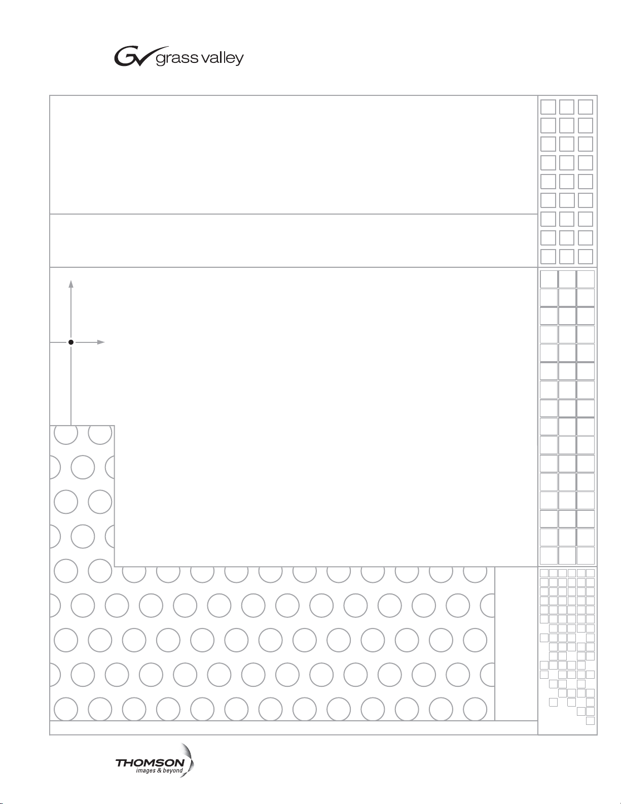
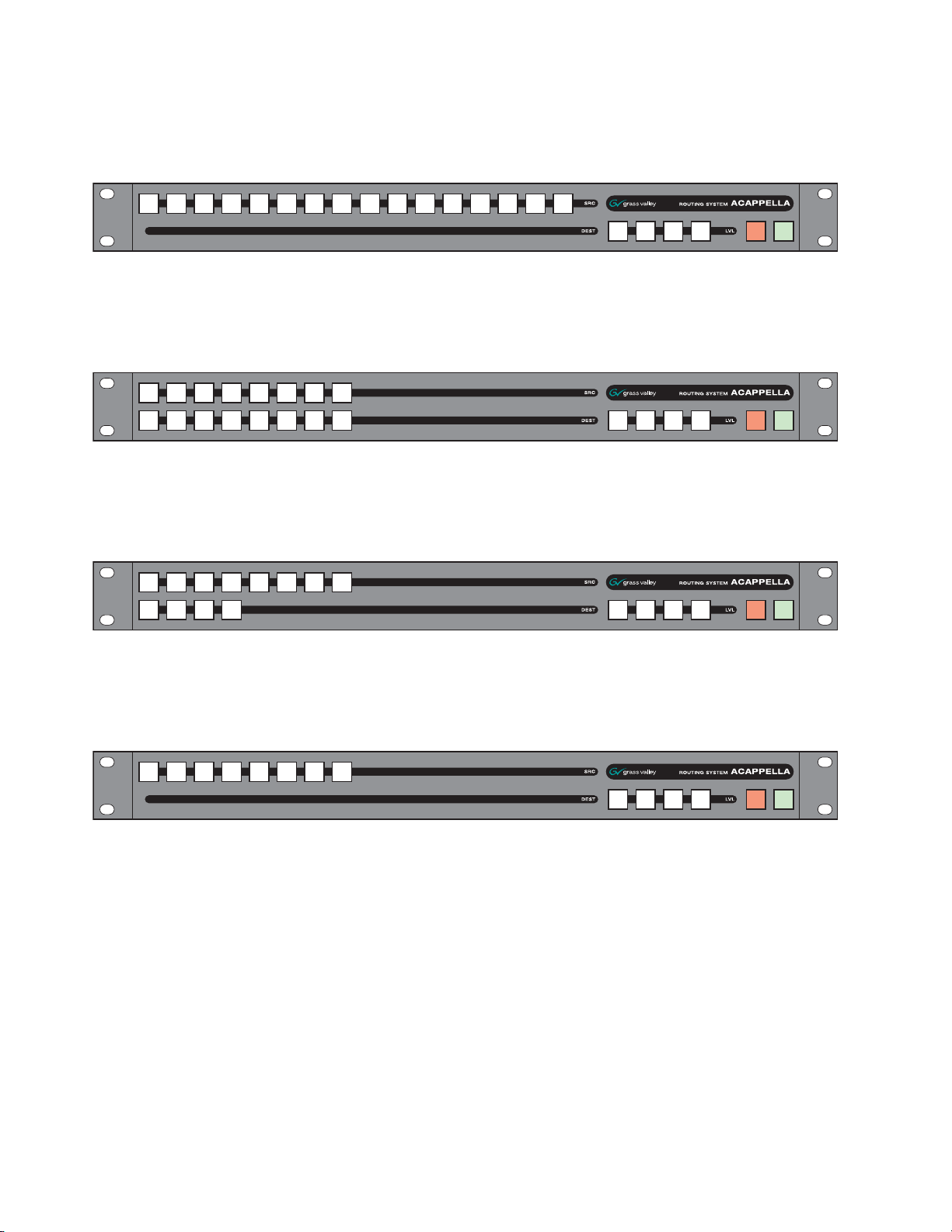
All panel fronts (except frames with no Local Panel) will have four Level
buttons, a green Enable button, and a red Protect button. The number of
Source and Destination buttons will change depending on the frame’s configuration for local panels and the desi
red configuration for remote panels.
Figure 2 is a panel with 16 Sour
Figure 2. 16x16 Front
ces and 16 Destinations.
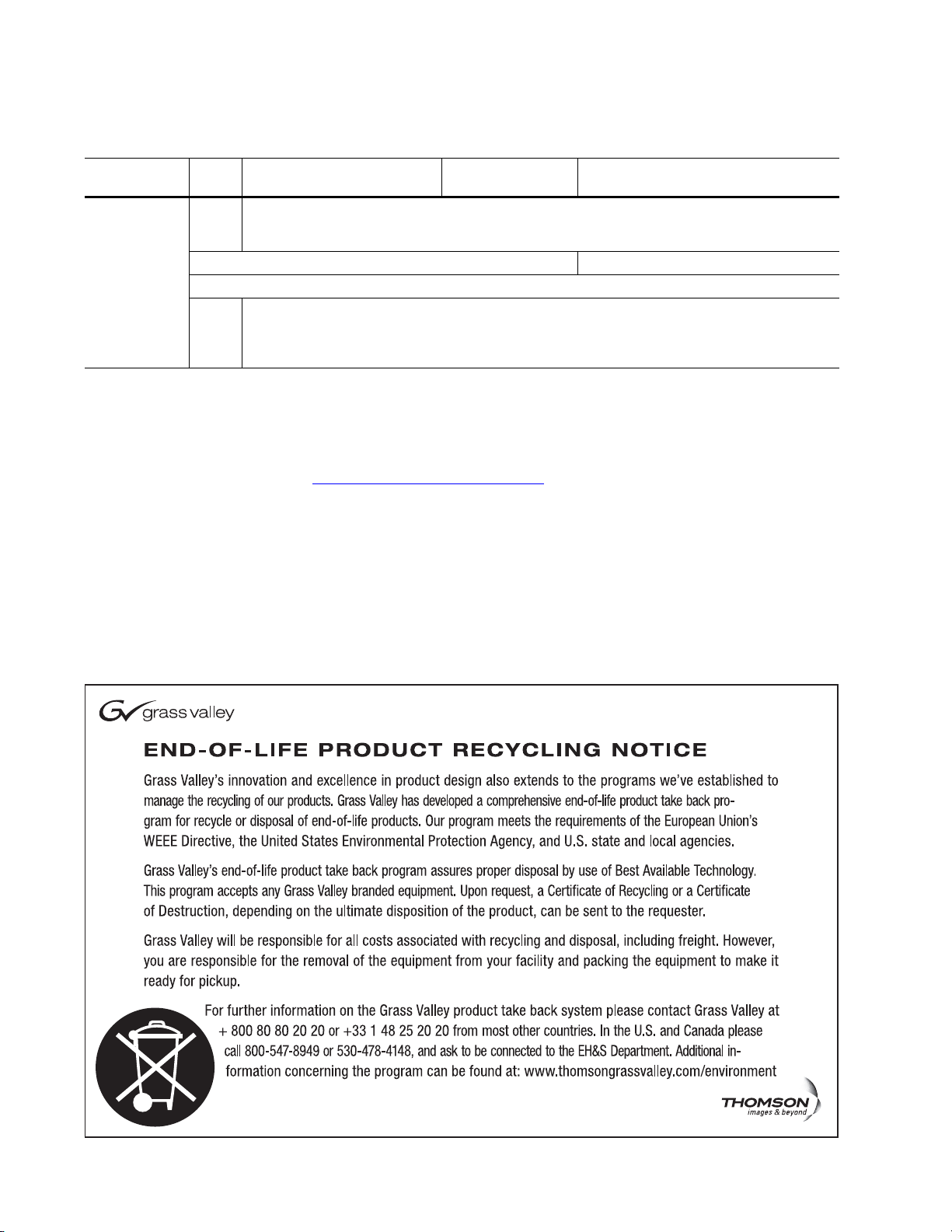
Figure 3 is a panel with 16 Sources and 8 Destinations.
Figure 3. 16x8 Front
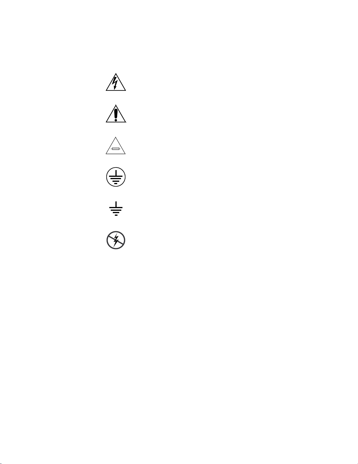
Figure 4 is a panel with 16 Sources and 4 Destinations.
Figure 4. 16x4 Front
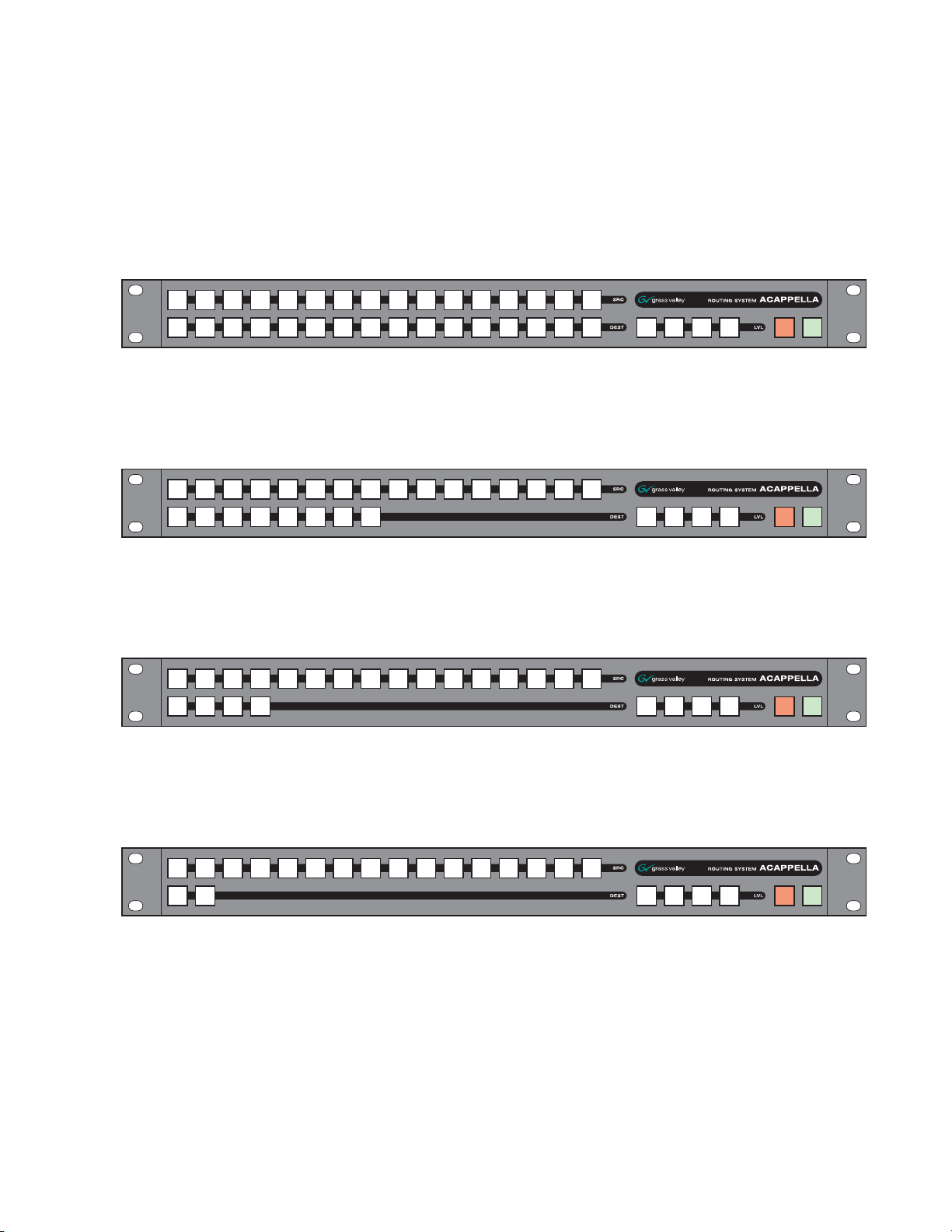
Figure 5 is a panel with 16 Sources and 2 Destinations.
Figure 5. 16x2 Front
Acappella — Instruction Manual 19
Page 20
Section 1 — System Overview
8300_00_12r0
8300_00_13r0
8300_00_14r0
8300_00_16r0
Figure 6 is a Remote panel with 16 Sources and 1 Destination.
Figure 6. 16x1 Single Destination Front (Remote Panel Only)
Figure 7 is a panel with 8 Sources and 8 Destinations.
Figure 7. 8x8 Front
Figure 8 is a panel with 8 Sources and 4 Destinations.
Figure 8. 8x4 Front
Figure 9 is a Remote panel with 8 Sources and 1 Destination.
Figure 9. 8x1 Single Destination Front (Remote Panel Only)
20 Acappella — Instruction Manual
Page 21
Backplanes
8300_00_20
1
16
15
2
14
13
12
11
3
10
9
4
16
15
5
14
13
6
12
11
7
8
7
8
6
5
9
4
3
10
2
1
V
I
D
E
O
8300_00_23
1
16
15
2
14
13
12
11
3
10
9
4
16
15
5
14
13
6
12
11
7
8
7
8
6
5
9
4
3
10
2
1
V
I
D
E
O
Hardware Description
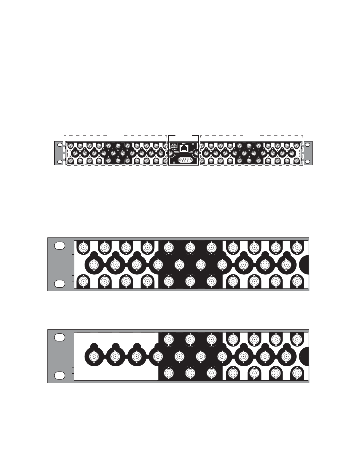
When viewed from the rear, the Acappella backplane is divided as shown
in Figure 10. The control area in the center will
Audio section on the right and the Video section on the
appear on all frames. The
left will change
depending upon the configuration of the frame. Inputs are indicated by
white numbers in the black area, are located in the top and bottom row of
the black area, and the entire middle row. Outputs are indicated by black
numbers in the white areas and are located in the top and bottom rows of
the white areas.
Figure 10. Acappella Backplane
Video Audio
Control
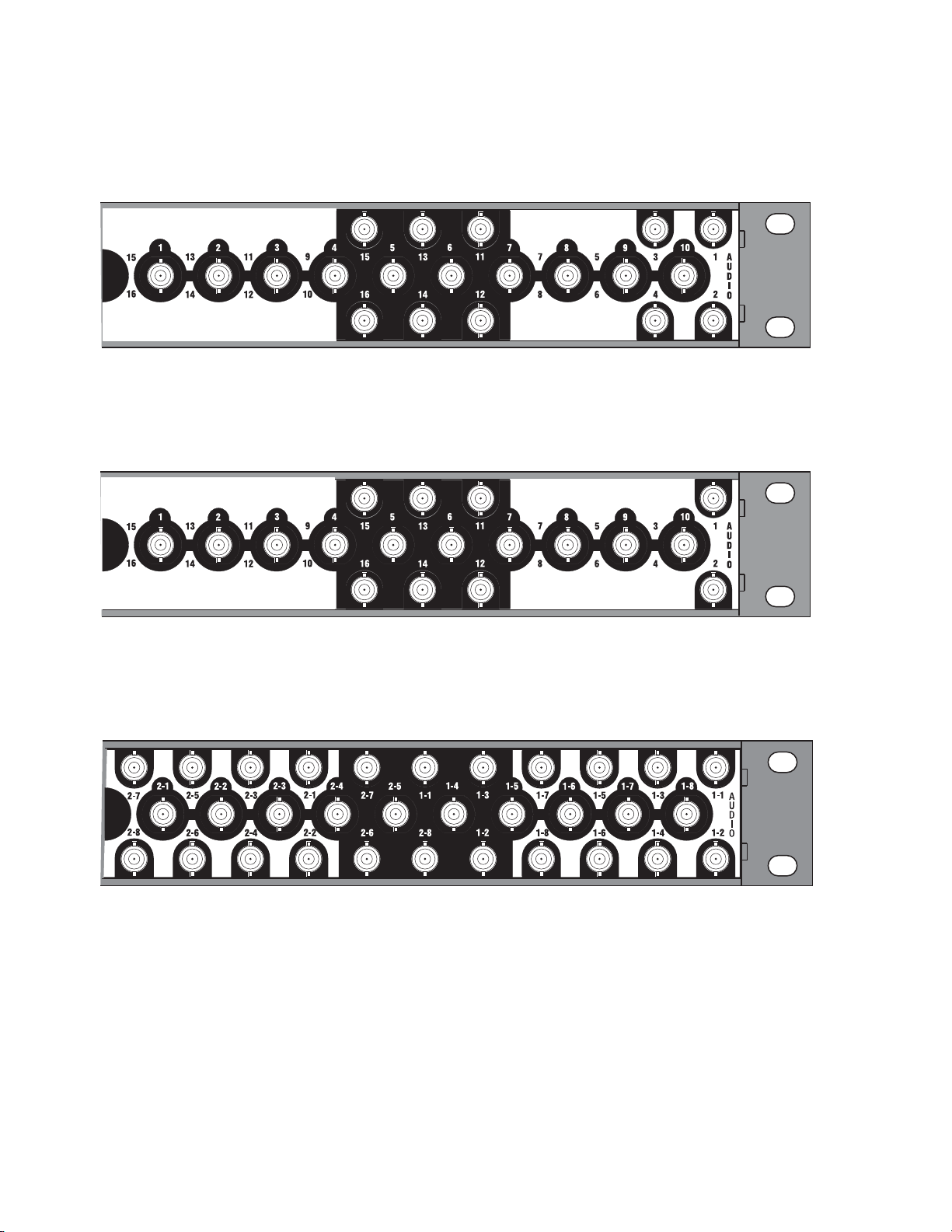
Video Configuration (Digital and Analog)
The video BNC backplanes are used with all signal types including High
Definition, Standard Definition, reclocking or non reclocking, and Analog.
The configuration shown in Fi
Figure 11. 16x16 Video BNC Backplane
gure 11 is 16 Inputs by 16 Outputs.
8300_00_34
The configuration shown in Figure 12 is 16 Inputs by 8 Outputs.
Figure 12. 16x8 Video BNC Backplane
Acappella — Instruction Manual 21
Page 22
Section 1 — System Overview
8300_00_24
1
16
15
2
14
13
12
11
3
10
9
4
16
15
5
14
13
6
12
11
7
8
7
8
6
5
9
4
3
10
2
1
V
I
D
E
O
8300_00_25
1
16
15
2
14
13
12
11
3
10
9
4
16
15
5
14
13
6
12
11
7
8
7
8
6
5
9
4
3
10
2
1
V
I
D
E
O
8300_00_21
1
2
3
4
5
6
7
8
7
8
6
5
4
3
2
1
V
I
D
E
O
1
16
15
2
14
13
12
11
3
10
9
4
16
15
5
14
13
6
12
11
7
8
7
8
6
5
9
4
3
10
2
1
V
I
D
E
O
8300_00_22
1
16
15
2
14
13
12
11
3
10
9
4
16
15
5
14
13
6
12
11
7
8
7
8
6
5
9
4
3
10
2
1
V
I
D
E
O
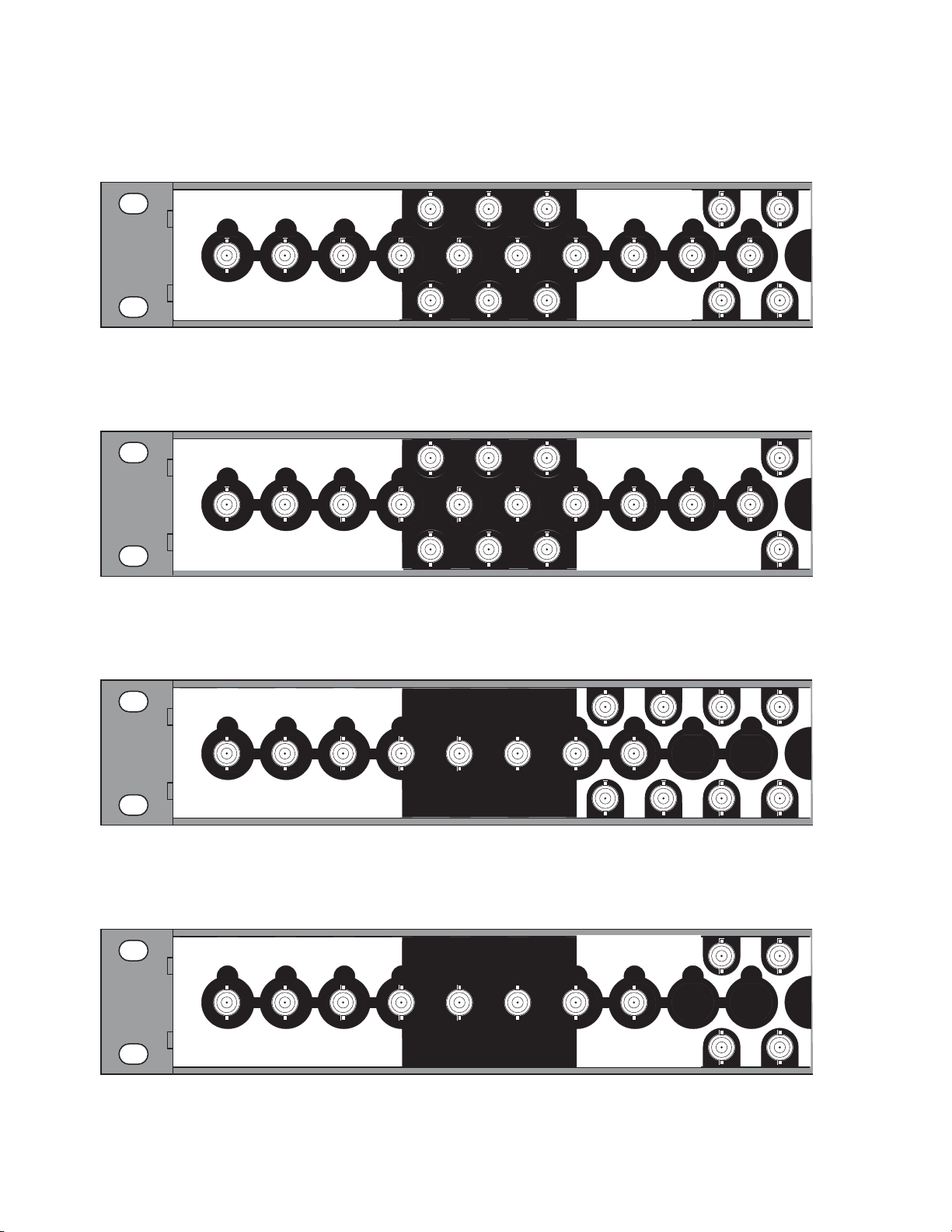
The configuration shown in Figure 13 is 16 Inputs by 4 Outputs.
Figure 13. 16x4 Video BNC Backplane
The configuration shown in Figure 14 is 16 Inputs by 2 Outputs.
Figure 14. 16x2 Video BNC Backplane
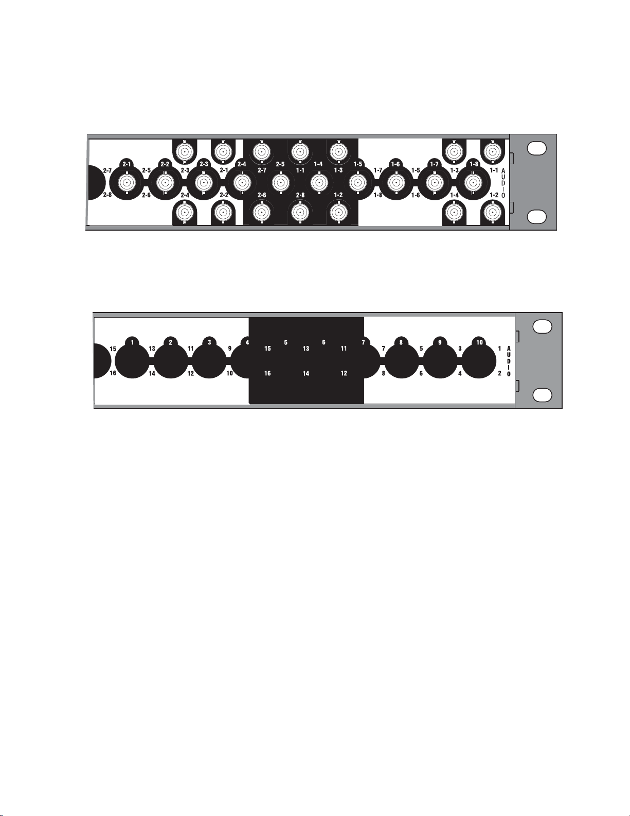
The configuration shown in Figure 15 is 8 Inputs by 8 Outputs.
Figure 15. 8x8 Video BNC Backplane
The configuration shown in Figure 16 is 8 Inputs by 4 Outputs.
Figure 16. 8x4 Video BNC Backplane
22 Acappella — Instruction Manual
Page 23
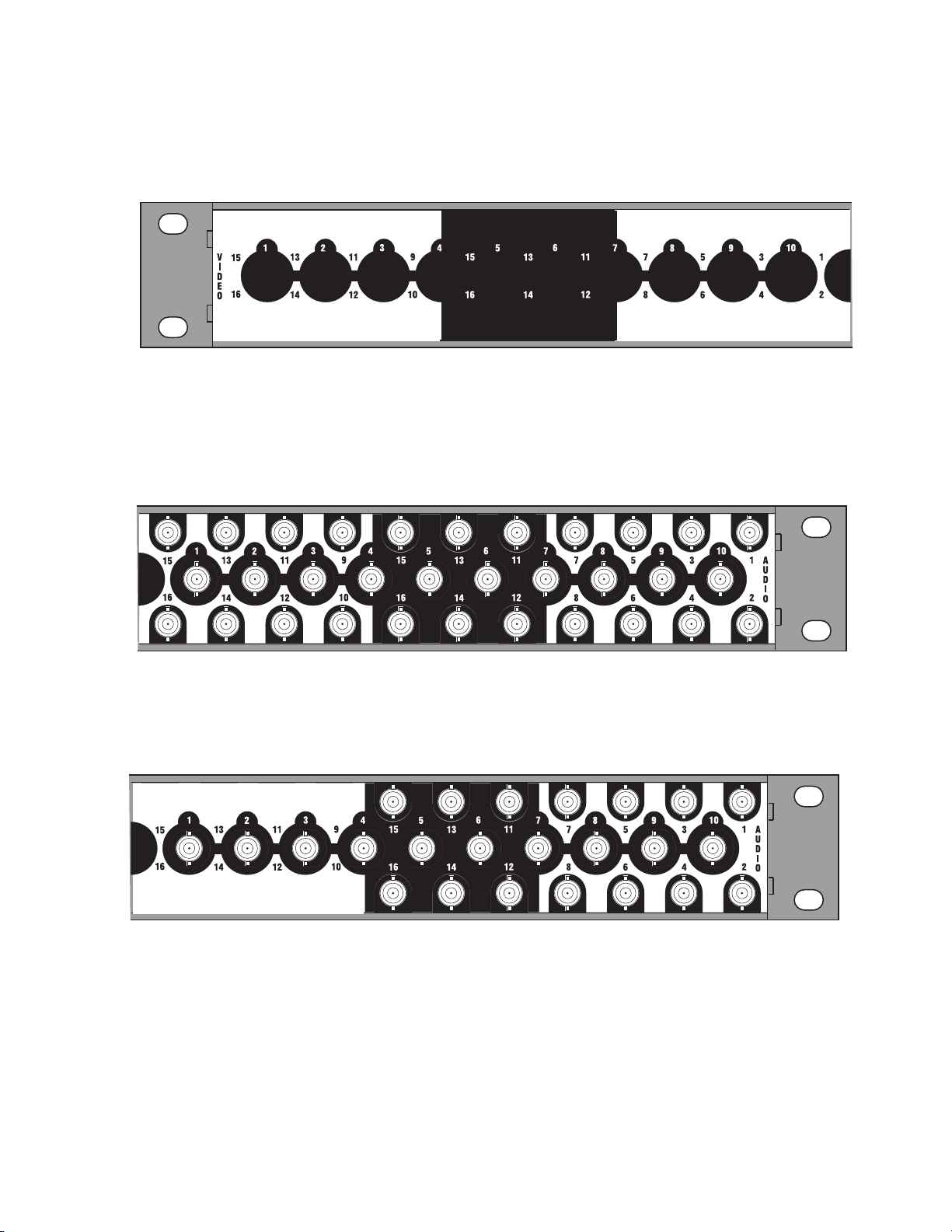
The empty configuration shown in Figure 17 is used on systems that have
8300 00 35
8300_00_27
audio with no video.
Figure 17. Empty Video Backplane
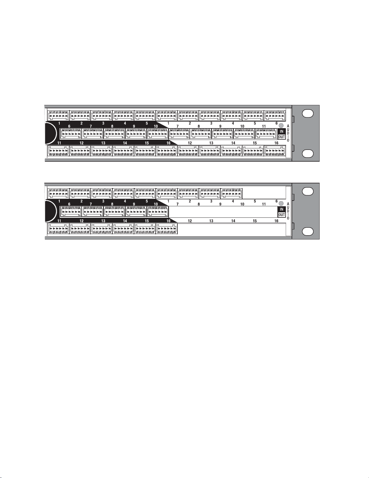
Digital Audio Configuration
The configuration shown in Figure 18 is 16 Inputs by 16 Outputs of single
stream digital (AES) audio.
Figure 18. 16x16 Audio Single Stream BNC Backplane
Hardware Description
8300_00_26
The configuration shown in Figure 19 is 16 Inputs by 8 Outputs of single
stream digital (AES) audio.
Figure 19. 16x8 Audio Single Stream BNC Backplane
Acappella — Instruction Manual 23
Page 24
Section 1 — System Overview
8300_00_28
8300_00_29
8300_00_32
The configuration shown in Figure 20 is 16 Inputs by 4 Outputs of single
stream digital (AES) audio.
Figure 20. 16x4 Audio Single Stream BNC Backplane
The configuration shown in Figure 21 is 16 Inputs by 2 Outputs of single
stream digital (AES) audio.
Figure 21. 16x2 Audio Single Stream BNC Backplane
The configuration shown in Figure 22 is 8 Inputs by 8 Outputs of dual
stream digital (AES) audio.
Figure 22. 8x8 Audio Dual Stream BNC Backplane
24 Acappella — Instruction Manual
Page 25
Hardware Description
8300_00_33
8300_00_36
The configuration shown in Figure 23 is 8 Inputs by 4 Outputs of dual
stream digital (AES) audio.
Figure 23. 8x4 Audio Dual Stream BNC Backplane
The empty configuration shown in Figure 24 is used on systems that have
video with no audio.
Figure 24. Empty Audio Backplane
Acappella — Instruction Manual 25
Page 26
Section 1 — System Overview
8300_02_54_r0
8300_02_58_r0
Analog Audio Configuration
Analog audio backplanes are equipped with Phoenix connectors that each
carry two balanced audio channels (typically left and right stereo). Inputs
are located on the left, and outputs are located on the right (as viewed from
the rear). Representative analog audio backplanes are shown below.
Figure 25. 16 x 16 Analog Audio
Figure 26. 16 x 4 Analog Audio
Note The bottom row of analog audio connectors are mounted upside down in
relation to the top two rows, due to internal board space limitations. The
removable connectors are wired the same regardless of row used.
Analog frames also offer a Dual Stereo configuration, which divide the
matrix into two groups with independent inputs and outputs. Inputs for
one group can only be routed to outputs of the same group, not to outputs
of the other group. The inputs and outputs of each group are labeled with
a leading number, 1- or 2-. Two Dual Stereo analog configurations are available, one with eight outputs per group Figure 27), and the other with four
outputs per group (Figure 28).
26 Acappella — Instruction Manual
Page 27
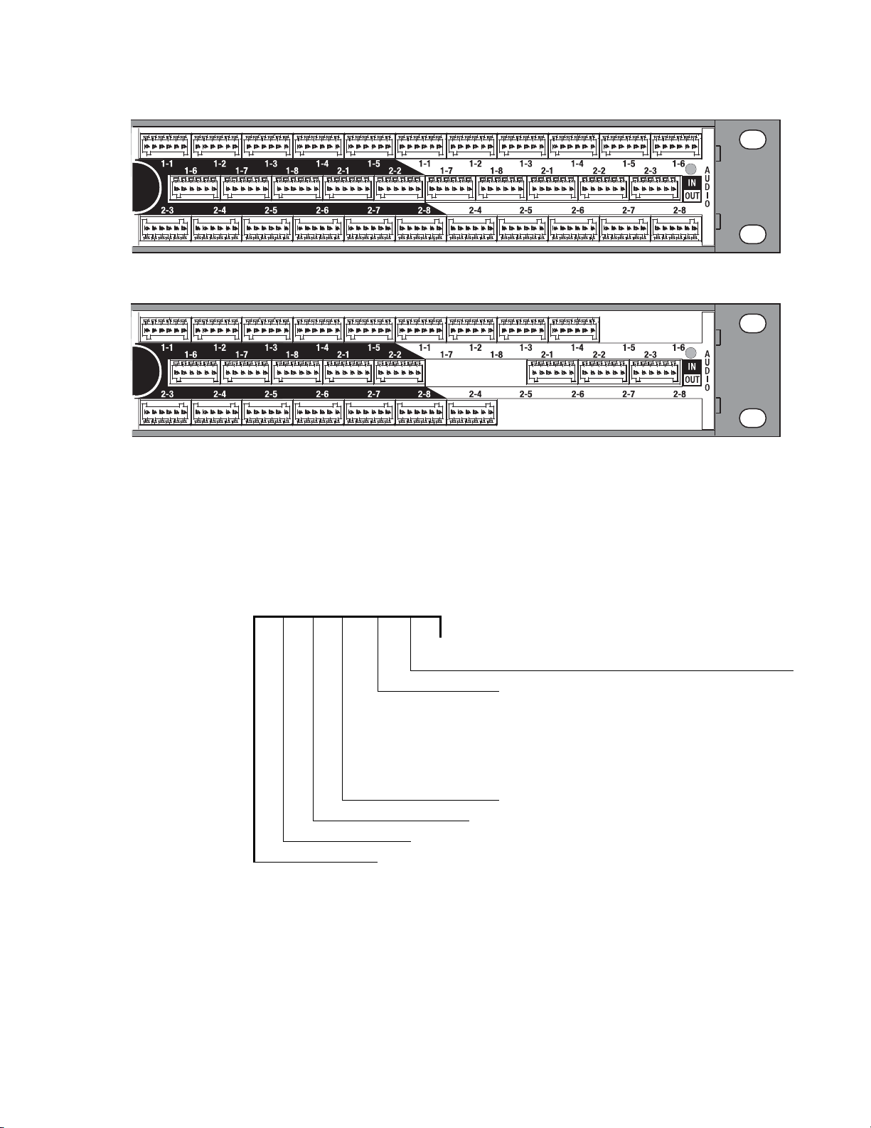
Figure 27. 8 x 8 Dual Stereo Analog Audio
8300_02_57_r0
Figure 28. 8 x 4 Dual Stereo Analog Audio
Hardware Description
8300_02_55_r0
Acappella Router and Remote Panel Variations
Acappella routers are available in single and dual formats with a variety of
inputs and outputs. Options include an integral control panel on the front
of the router and redundant power supplies. Table 2 shows how the model
number of the Acappella router identifies
Table 2. Acappella Routers Example Model Code
A 16 8 HR- DU- L P
Chassis Options, L= Local control panel
Secondary Signal Format V = Analog video
Primary Signal Format
Number of Outputs: 2, 4,
Number of Inputs: 8 or 16
A = Acappella
8, or 16
the configuration of the frame.
P = Internal redundant power supply (digital only)
S = SD video
SR = SD video w/reclocking
HR = HD video w/reclocking
AU = AES audio, unbalanced 75 Ohm BNC
AB = AES audio, balanced 110 Ohm terminals
DU = Dual AES audio, balanced, 110 Ohm terminals
DBT = AES audio, transformer
AA = Dual-channel, analog audio, balanced
QA = Dual stereo analog audio
coupled, 110 Ohm terminals
Acappella — Instruction Manual 27
Page 28

Section 1 — System Overview
Acappella Remote Control panels are also available in many different configurations (Ta bl e 3).
Table 3. Acappella Remote Control Panels Example Model Code
A 16 1 RCP GPI
A = Acappella
GPI Joystick Override
Indicates Remote Control Panel
Number of Outputs: 1, 2, 4, 8, or 16
Number of Inputs: 8 or 16
28 Acappella — Instruction Manual
Page 29
Installation
8103_00_37
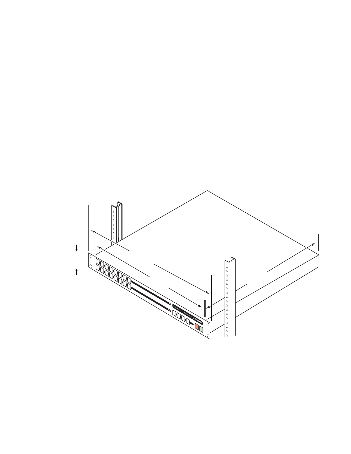
44 mm
1.75 in.
432 mm
17 in.
392 mm
15.43 in.
483 mm
19 in.
Measurements do not
include clearance for cables.
Acappella Frame Rack Installation
The Acappella frame is installed in a standard 483 mm (19 inch) rack. The
frame occupies 1 rack unit. Cooling is by horizontal front-to-back airflow.
See Figure 29.
Figure 29. Acappella Installation Front View
Section 2
Note The depth shown is for the frame. Additional space is needed for cable clear-
ances.
Acappella — Instruction Manual 29
Page 30
Section 2 — Installation
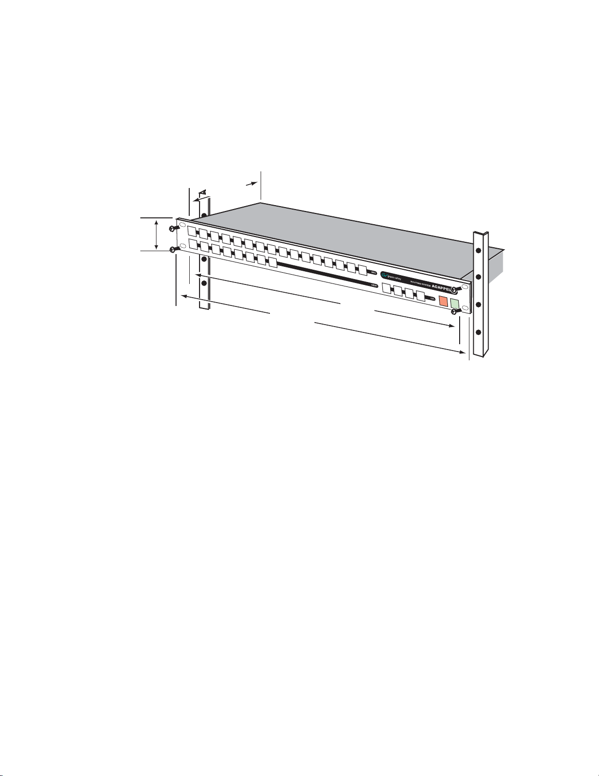
Remote Panel Rack Installation
Remote panel rack mounting is straightforward and requires no special
tools or adaptors. Simply position the Remote Panel in the rack and secure
the panel in place. Refer to Figure 30.
Figure 30. Rack Mount Remote Panel Installation
44 mm
1.75 in.
106 mm
4.18 in.
483 mm
19 in.
Measurements do not include clearance for cables.
432 mm
17 in.
8300_00_48r0
A rear frame support kit is available as an option (ACAP24RACKKIT).
30 Acappella — Instruction Manual
Page 31

Acappella Cabling
8300_00_04
Video Outputs
1, 3, 5, & 7
Video Outputs
9, 11, 13, & 15
Video Inputs
11, 13, & 15
Video Outputs
2, 4, 6, & 8
Video Outputs
10, 12, 14, & 16
Video Inputs
12, 14, & 16
Audio Outputs
1, 3, 5, & 7
Audio Outputs
9, 11, 13, & 15
Audio Inputs
11, 13, & 15
Audio Outputs
2, 4, 6, & 8
Audio Outputs
10, 12, 14, & 16
Audio Inputs
12, 14, & 16
Video Inputs
1, 2, 3,
4, 5, 6,
7, 8, 9,
& 10
Audio Inputs
1, 2, 3,
4, 5, 6,
7, 8, 9,
& 10
Ethernet
Reference
Loop
Reference Loop
75 ohm Terminator
Redundant
Power Supply
Power
Supply
Serial
RS-422
Figure 31 shows all possible cabling for a 16x16 Acappella frame with 16
Video Inputs and Outputs and 16 single stream AES Audio Inputs and
Outputs using BNC connectors.
Figure 31. 16x16 Cabling
Acappella Cabling
The second Power Supply is optional.
Acappella — Instruction Manual 31
Page 32

Section 2 — Installation
8300_00_05
Video Outputs
1, 3, 5, & 7
Video Outputs
2, 4, 6, & 8
Audio Outputs
1-1, 1-3,
1-5, & 1-7
Audio Outputs
2-1, 2-3,
2-5, & 2-7
Audio Outputs
1-2, 1-4,
1-6, & 1-8
Audio Outputs
2-2, 2-4,
2-6, & 2-8
Video Inputs
1, 2, 3,
4, 5, 6,
7, & 8
Audio Inputs
1-1, 1-2,
1-3, 1-4,
1-5, 1-6,
1-7, & 1-8
Audio Inputs
2-1, 2-2,
2-3, 2-4,
2-5, 2-6,
2-7, & 2-8
Reference Loop
75 ohm Terminator
Reference
Loop
Ethernet
Redundant
Power Supply
Power
Supply
Serial
RS-422
Figure 32 shows all possible cabling for an 8x8 Acappella frame with 8
Video Inputs and Outputs and 8 dua
l stream AES Audio Inputs and
Outputs using BNC connectors. The second Power Supply is optional.
Figure 32. 8x8 Cabling
32 Acappella — Instruction Manual
Page 33

Analog Audio Pinouts
Phoenix style connectors are used for wiring analog audio. Space limitations required the bottom row of connectors be oriented upside down, but
the r
emovable connectors are wired the same regardless of row used.
Figure 33. Analog Audio Backplane
Figure 34. Phoenix Connector Pinouts for Stereo Analog Audio
Top 2 Rows (connector right side up)
Acappella Cabling
8300_02_54_r0
+ - G + - G
A B
+ - G + - G
Ch A (Left)
Ch B (Right)
Bottom Row (same connector upside down)
G - + G - +
B A
Ch A (Left)
Ch B (Right)
8300_02_56_r0
Acappella — Instruction Manual 33
Page 34

Section 2 — Installation
8300_00_38
Reference Loop
75 ohm Terminator
Ethernet
Serial
RS-422
Reference
Loop
5
6
9
1
9 Pin D Female
Control Cabling
Ta bl e 4 shows the connectors in the Control area of the Acappella frame.
Table 4. Control Cabling
Label
ENET RJ-45 Female Ethernet network communication interface is 100Base-T compatible, use
SERIAL 9 pin D Female RS-422 interface, use serial cable.
REF LOOP BNC Female Video reference supports Color Black or Tri-Level-Sync, use unbalanced 75
Connector
Type Gender
Details
Category 5e cable, 8 conductor twisted pair.
ohm connecto
r, Loop-thru cabling supported.
Serial 9 Pin D Connector Pinout
Ta bl e 5 contains pinout information for the Serial RS-422 9 Pin D connector.
Table 5. Serial D Connector Pinouts
Note Refer to the latest version of the Routing Products Protocols Manual for
Ethernet Cabling
The Acappella frame uses Ethernet to communicate. Use standard pin-topin (patch) Category 5e cables if you are using switches between the
routers, panels, and PC. It is also possible to use a crossover cable to
connect an Acappella Router directly to either a Remote Panel or a PC; this
option is only practical in very small systems. Figure 35 shows a Closed
Network system with an Acappella router
nected to a switch.
Controlled Pin Function Pin Function
GND
1
TX-
2
RX+
3
RX Com
4
NC
5
TX Com
6
TX+
7
RX-
8
GND
9
-
-
information about the Terminal/Computer Interface (T/CI) Protocol used to
control Acappella systems. This manual is available for download on the
Grass Valley web site (see page 4).
, a Remote Panel, and a PC con-
34 Acappella — Instruction Manual
Page 35

Figure 35. Ethernet Cabling
8300_01_44
Acappella
Remote Control Panel
Ethernet Switch
PC-compatible
8300_00_50
75 ohm
Terminator
Reference Generator
8300_00_39
75 ohm Terminator
Reference Generator
AES Signal
Reference Cabling
Reference signals are loop-thru with the end of the chain terminated. Color
Black or Tri-Level Sync signals are used. The Reference shown in Figure 36
is the default cabling for plug and play.
Figure 36. Video Reference Connections
Acappella Cabling
See Router Reference Configuration Page on page 73 to select AES Src 1
instead of the Color Black or Tri-Level Sync Refer
ence. Web Page configu-
ration is required
In Figur
Figure 37. Reference Signal Cabling Option for Single Stream Audio
e 37 a Continuous AES Signal is connected to Audio Input 1.
Acappella — Instruction Manual 35
Page 36

Section 2 — Installation
8300_00_40
75 ohm
Terminator
Reference Generator
AES Signal
8300_01_42r1
Female Plug Male Plug Female PlugMale Plug
Power SupplyRedundant Power Supply
In Figure 38 a continuous feed AES signal is connected to Audio Input 2-1.
Figure 38. Reference Signal Cabling Option for Dual Stream Audio
Remote Panel Cabling
The Remote Panel has connectors for RJ-45 Ethernet and AC Power. See
Figure 39.
Figure 39. Remote Panel Cabling
LANAC Power
Power
Digital Frames
The Acappella digital frame uses internal auto-ranging AC power supplies.
One Power Supply is standard, the optional second Power Supply is fully
redundant.
The frame ships with one or two captive power cor
cord (shipped with the frame) needs to be attached to each of the captive
power cords as shown in Figure 40
Figure 40. AC Power Supplies
ds. A separate power
8300_00_07r1
36 Acappella — Instruction Manual
Page 37

A bale clamp is provided to secure the power cords.
Bale
8300_00_43
INPUTS
OUTPUTS
ENET
REF
LOOP
J2
J1
SERIAL
PWRPWRPWRPWR
8300_02_59r0
Female Plug
Female Plug
Male Plug
Male Plug
Power Supply
Redundant Power Supply
Figure 41. Power Cord Bale Clamp
Analog Frames
The Acappella analog frame uses external auto-ranging AC power supplies. The power supplies connect to the rear of the frame (Figure 40).
Figure 42. External Power Supplies
Defaults for Plug and Play
Defaults for Plug and Play
Default Levels are determined by the router’s physical configuration. A
router with a physical configuration of 8x8HR-DU would have 3 default
Levels; Level 1 is HD wideband reclocking serial digital Video, Level 2 is
AES digital Audio 1, Level 3 is AES digital Audio 2.
The default AES digital Audio attributes are;
20 bit
Audio mode: Normal, Resolution:
, and Block Align: On. All other AES digital Audio attributes are inactive.
Acappella — Instruction Manual 37
Page 38

Section 2 — Installation
38 Acappella — Instruction Manual
Page 39

Panel Operation
8300_00_52r0
1122334
4
Lvl 1 Lvl 2 Lvl 3 Lvl 4
5566778 9 10 11 12 13 14 15 16
8
EnabProt
Levels
On Indicators
Destinations
Sources
Protect Enable
Local Panels and Remote panels expand the functionality of the Acappella
router.
A frame that has 8 Inputs, 4 Outputs, digital video and Dual Stream digital
AES audio, would have thr
• Eight inputs and four outputs of video,
• Eight inputs and four outputs of audio, and
• A second set of eight inputs and four outputs of audio.
ee Levels of 8 inputs and 4 Outputs as follows:
Section 3
Enable Button
Enable Button Action
The On Indicators will be lit when there is power to the panel. See Figur
Button illumination will be either Off, Ba
depending on the button’s status.
Figure 1. 16x8 Local Panel Layout
The Enable button is green and is found on the lower right of the panel. See
Figure 1.
cklit, Low Tally, or High Tally
e 1.
Acappella — Instruction Manual 39
Press and release of an active Enable button causes the following actions:
• Deactivates the panel,
• Inactive
•The
Enable button is illuminated at Backlight Tally, and
Protect and Source buttons do not operate.
Page 40

Section 3 — Panel Operation
Protect Button
Press and release of an inactive Enable button causes the following actions:
• Activates the panel, and
• Active Enable button is illuminated at High Tally.
Other button activity on an inactive panel (not enabled):
• Source Tally (on active Destinations) is displayed normally,
• Active Destination can be changed (by press and release of another
Destination button) to view Source status on the new Destination,
• Levels can be changed to view Source status on any Level, and
• A Destination Gang preset can be created, but not Taken.
No change is allowed to the current Source on a protected Destination,
either by action on this panel, or by any remote device (via ethernet) action.
Any device can enable or disable the Destination protection. The
button is red and is found on the lower right of the panel. See
Protect
Figure 1.
Protect Button Action
Press and release of the inactive Protect button to activate a Protect causes
the following actions:
• Active Protect button is illuminated at High Tally,
• Activates Protect status on the active Destinations, and
• All Destinations in a Destination Gang are protected.
Press and release of the active Protect button causes the following actions:
• Inactive Protect button is illuminated at Off Tally,
• Deactivates Protect on the active Destinations, and
• All Destinations in a Destination Gang are removed from the Protected
state.
40 Acappella — Instruction Manual
Page 41

Source Button
Single Source Button Action
Source Button
Press and release of a single Source button causes the following actions:
• Connects a Source to the active Destination on all active Levels,
• Tallys only the active Source at High Tally illumination intensity,
• All other Sources become inactive at Backlight Tally illumination intensity,
If a Breakaway,
• The single Source button is High Tally,
• The left most active Level button is High Tally,
• The Breakaway level is low tally, and
• Inactive Level Tally remains at Backlight intensity,
If Chop function is active (Local Panel),
• Press and release of a Source button inactivates the Chop, and
• Connects the Source to the active Destination,
Note Chop is a toggle between two Sources to a single Destination.
If Destination Gang and All Levels are active (Local Panel),
• Press and release of a Source button connects that Source to all Destinations in the Gang,
•All Destination buttons (in the Gang) are High Tally, and
• Active All Level button Tally is updated to High Tally,
If Destination Gang is active, but not All Levels active (Local Panel),
• Press and release of a Source button connects that Source to all Destinations in the Gang for only the active Levels,
• The individual Destination buttons (in the Gang) are either Low Tally to
indicate Breakaway, or High Tally to indicate no Breakaway, and
•All active Level button Tally is updated to indicate either Breakaway as
Low Tally, or no Breakaway as High Tally.
Note Chop is not available on a Remote Panel. The Chop will only be on the Local
Panel and on the Local Levels output. It will not change the output of the
Remote Levels in the system. However, if any Source is selected by any panel
in the system it will stop the Chop.
Acappella — Instruction Manual 41
Page 42

Section 3 — Panel Operation
Multiple Source Button Action (Local Panel)
Press and release of a Source button while press and hold of the current
Source button causes the following actions:
• Initiates the Chop function between two Sources on a single Destina-
• If Destination Gang is currently active, Chop will not invoke, and
•Both Source buttons are High Tally during active Chop function.
After Chop function is activated, press of any button will inactivate the
Chop.
Note Chop is not available on a Remote Panel. The Chop will only be on the Local
Destination Button
tion,
Panel even in systems that have remote levels. However, if any Source is
selected by any panel in the system it will stop the Chop.
Single Destination Button Action
Single Destination button press and release causes the following actions:
• Activates that Destination,
• Inactivates all other Destinations,
• Active Destination button is High Tally,
• Inactive Destination buttons are Backlight Tally,
• Updates the Source Tally and active Level Tally to reflect the active Destination status,
• Inactive Level Tally remains at Backlight Tally, and
• Destination Gang is cancelled.
Multiple Destination Button Action
Press and release of a Destination button while press and hold of active Des-
tination button will create a Destination Gang condition with the following
actions:
• A second press and release of a secondary Destination button (while the
primary
that Destination from the Destination Gang,
Destination button is still depressed) will drop or add (toggle)
• If any Destination is currently Protected, that Destination will not be
added to the Gang,
42 Acappella — Instruction Manual
Page 43

Level Button
Single Level Button Action
Level Button
When a secondary Destination is added to the Destination Gang,
• High Tally if it is connected to the same Source (on all active Levels) as
the primary Destination,
• Low Tally if it is connected to a different Source (on any active Level) as
the primary Destination, and
•All active Level button Tally is updated to indicate either Breakaway as
Low Tally, or no Breakaway as High Tally.
The left most enabled Level button is the Tally Level, it is High Tally and the
Source Tally is updated to be the Source on this Level.
Press and release of a disabled Level button causes the following actions:
• Activates the Level,
• High Tally if the Source connected on that Level is the same Source as
the left most Tally Level button,
• Low Tally if the Source connected on that Level is not the same Source
as the left most Tally Level button
Press and release of enabled Level button causes the following actions:
• Inactivates that Level, and
• Level button is Backlight Tally.
Acappella — Instruction Manual 43
Page 44

Section 3 — Panel Operation
Video Destination
Audio Destination
DVTR 3
Video Source B (VSB)
Audio Source B (ASB)
DVTR 2
Video Source A (VSA)
Audio Source A (ASA)
DVTR 1
Acappella
Video
Audio
VSB
ASB ASB
8300_00_45
ASA
ASA ASA
VSA
VSAVSA
Video Destination
Audio Destination
DVTR 3
Video Source B (VSB)
Audio Source B (ASB)
DVTR 2
Video Source A (VSA)
Audio Source A (ASA)
DVTR 1
Acappella
Video
Audio
VSA
VSA
ASA
VSA
ASA
VSB
ASB ASB
8300_00_46
ASB
Multi-Level Switching
There are two modes of multi-Level switching: All-Level Takes and Breakaway Takes. All-Level Takes switch the
to the controlled Destination, as shown in Figure 2.
Figure 2. Traditional All-Level Take
same input number on all Levels,
A Breakaway Take is performed by accessing the control Levels of a Destination individually and selecting a dif
other than that selected on the others. Breakaways allow a Destination to
selectively utilize video and audio from different Sources.
Figure 3. Breakaway Take
ferent Source on at least one Level
44 Acappella — Instruction Manual
Page 45

Section 4
Software and Configuration
Network Configuration
PC Requirements
A customer supplied PC is used for software installation and initial system
configuration. This PC must meet the following minimum requirements:
• 256 Mb RAM,
• 10 Mb available hard disk space,
• 100BaseT Ethernet Network Interface Card,
• Monitor with a screen resolution of 1024 x 768,
• Windows XP SP2 and above operating system,
• Logged in with Administrator-level privileges for the local machine,
and
• Internet Explorer version 6.0 or later.
PC Network Configuration
The PC you will use must be configured to operate on the Acappella standalone network. This is accomplished by setting the IP address of the PC to
be compatible with the IP addresses of the Acappella system components.
In general, the first three octets of the IP address must be the same, and the
last IP address octet must be unique for each device on the network.
See Tab le 1 on page 46 for a recommended IP address for your PC that will
work with an Acappella system using default network settings.
The exact method used to change the IP address of a PC varies, depending
on the computer’s operating system. Before changing the PC’s IP address
you should note down the existing values so you can easily reconfigure the
computer back to normal operation when finished using it with Acappella.
Acappella — Instruction Manual 45
Page 46

Section 4 — Software and Configuration
Default System IP Addresses
Acappella systems ship with default IP addresses shown in Tabl e 1.
Table 1. Acappella System Default IP Addresses
Device IP Address Subnet Mask Gateway
Acappella Matrix Frame 192.168.0.40 255.255.255.0 192.168.0.1
Acappella Remote Panel 192.168.0.41 255.255.255.0 192.168.0.1
User Provided PC
(recommended setting)
If your Acappella system has multiple frames and/or multiple remote
panels, these defaults will need to be changed. See Setting IP Addresses on
page 52 for specific instructions.
Software
192.168.0.1 255.255.255.0 192.168.0.1
Acappella ships with a software CD. Several applications on the CD enable
you to make adjustments to the Acappella configuration. After you have
added a PC to the Acappella network, you need to install the Acappella
software on the PC.
Software Installation
The Acappella Software CD will install the Acappella Matrix software,
Acappella Remote Panel software, NetConfig application (a Network Configuration Tool), NetConfig Instruction Ma
tion Manual on a PC.
1. Insert Acappella Software CD, it will autostart. If the CD does not start
look for the Setup.exe file.
nual, and the Acappella Instruc-
46 Acappella — Instruction Manual
Page 47

2. Click Next when the Welcome screen appears.
Figure 4. Welcome Window
3. Select I Agree, then click Next.
Software
Figure 5. License Windows
Acappella — Instruction Manual 47
Page 48

Section 4 — Software and Configuration
4. Click Next to accept the default directory or Browse to select a different
location for the directory.
Figure 6. Directory Window
5. Click Next to accept all the applications or deselect any applications you
don’t want and then click
Figure 7. Applications Window
Next.
48 Acappella — Instruction Manual
Page 49

Software
6. Click Yes to backup current files. This only applies to upgrading or
reinstalling the software.
Figure 8. Start Installation Window
7. Click Next to begin the Installation.
Figure 9. Start Installation Window
Acappella — Instruction Manual 49
Page 50

Section 4 — Software and Configuration
Status windows will appear while the software is loading.
Figure 10. Status Windows
8. Click Finish to complete the Installation.
NetConfig
Figure 11. Finish Window
The NetConfig application is designed to make network configuration
simple. NetConfig discovers devices on the network, and these devices can
be configured remotely using the PC on which NetConfig has been
installed. NetConfig incorporates a web browser that displays web pages
served by the devices on the network. NetConfig is also used for software
installation to these devices.
50 Acappella — Instruction Manual
Page 51

NetConfig
Acappella routers are shipped with the NetConfig client installed as are
many other Grass Valley products. Once the NetConfig software is
installed on a PC, you will be able to view and interact with all the NetConfig client devices on the same network.
To open NetConfig find the shortcut on the PC’s desktop.
The left side of the NetConfig application scr
the devices on the network. The root of the logical tree is the name and the
IP address of the PC on which NetConfig is running. The current status of
each discovered device is reported by the color of its icon. A red dot, for
example, indicates a device is no longer communicating, which might
mean it has been disconnected from the network.
The right portion of the screen is the web browser view. When you click a
device on
browser view on the right.
In a closed network, Acappella and an Acappella Remote panel would
ear as shown in Figure 12.
app
Figure 12. NetConfig Window
the left, the home page for that device is displayed in the web
een displays the logical tree of
Select the device that you want to view from either the IP View or the
Device View. See Acappella Configuration Pages on page 57 for details.
Acappella — Instruction Manual 51
Page 52

Section 4 — Software and Configuration
NetConfig Manual
A NetConfig manual .pdf file is installed onto the PC along with the NetConfig application. The manual is located
in the NetConfig directory.
Setting IP Addresses
In systems that have more than one Acappella router and/or more than one
Remote Panel the IP Addresses need to be changed, since the same device
types ship with the same IP addresses (see Default System IP Addresses on
page 46). Resolving duplicate IP addresses
NetConfig. If a device is
as another device, when the new device is discovered a warning message
will be displayed. The IP View will also show the two devices with the
same address with an IP symbol as shown in Figure 13. This can occur if
new devices with factory default IP add
Figure 13. Devices with Duplicate IP Addresses
in a Documentation subdirectory
is easily accomplished with
installed on the network with the same IP address
resses are installed on the network.
To Resolve Duplicate IP addresses:
1. Select the NetConfig Set IP icon on the toolbar or the Device IP
Addresses in the Configure pull-down.
52 Acappella — Instruction Manual
Page 53

Figure 14. Set IP
Set IP button
2. Highlight one of the devices with a duplicate IP address.
Figure 15. Duplicate IP
NetConfig
3. Click Edit, then change the last octet of at device’s IP address to be
unique. The first three octets of all the IP addresses must be identical,
so all the devices are on the same network.
Figure 16. Change IP
Acappella — Instruction Manual 53
Page 54

Section 4 — Software and Configuration
Load SW button
4. Click Apply Changes. The device resets, and the new IP address will be
reported in the left pane of NetConfig screen.
Figure 17. New IP Address
Load Software
When all devices have unique IP addresses, it can be extremely helpful to
label each device with its currently assigned IP address. Sticky labels that
can be removed are advisable, since the IP address may be changed in the
future. To identify a specific remote panel when several are connected at
once, send a reset command to a panel and see which front panel buttons
go off and back on.
Use NetConfig to load software to Acappella routers and Acappella
Remote Panels.
1. Open NetConfig and select the Load SW button in the toolbar.
Figure 18. Load SW
54 Acappella — Instruction Manual
Page 55

NetConfig
2. The Load Software window will open with Router displayed. Navigate
through the folders to view the latest versions of Acappella panel and
matrix software available for loading, as shown in Figure 19.
Figure 19. Update Devices Window
3. Highlight Acappella Matrix for Acappella matrices. Matrices will appear
in the right pane of the window, see Figure 20.
Figure 20. Acappella Matrix
4. Check the box for the Acappella to update in the Client Name list.
5. Check the Re-Boot when complete checkbox in the lower lefthand corner to
have the matrix re-boot when the software update is complete.
6. Click the Load button to begin the update.
7. Once all matrix downloads are complete, use the Refresh button to
update the window and check that the version of software has been
downloaded to each selected device successfully.
Acappella — Instruction Manual 55
Page 56

Section 4 — Software and Configuration
8. Highlight Acappella Panel bin for Remote Panels. The Remote Panels on
the network will appear in the right pane of the window, see Figure 21.
Figure 21. Remote Panels
9. Check the box for the Acappella Remote Panel to update in the Client
Name
list.
10. Check the Re-Boot when complete checkbox in the lower left corner to have
the panel(s) re-boot when the software update is complete.
11. Click the Load button to begin the update.
12. Once all Panel downloads are complete, use the Refresh button to
update the window and check that the version of software has been
downloaded to each selected device successfully.
13. When finished, select the Close button.
Web Browser Interface
Enter the IP address set for the Acappella matrix frame or Remote panel
into a web browser to access the Acappella configuration pages. If you
don’t know what these IP addresses are, you can use NetConfig to see the
IP Addresses of all the devices on that network.
56 Acappella — Instruction Manual
Page 57

Acappella Configuration Pages
Refresh Button
Router Configuration
Acappella routers use a set of web pages to provide information and to
allow user defined configuration changes. The pages are accessed by either
NetConfig or a web browser.
Router Status Page
The Router Status page is a read only page. Some of the information displayed here is entered automatically such as Pr
Number, etc. The Location and Asset Tag can be changed on a different
page. The Level, Source (SRC), and Destination (DST), Crosspoint status
will reflect the current state of the router when the page was accessed. To
update the Crosspoint information click on the
Figure 22. Router Status Page
Acappella Configuration Pages
oduct Part Number, Serial
Refresh button.
Refresh Button
An refresh button icon located at the top of this and other Acappella web
pages updates the web page with the latest information (Figure 22).
Acappella — Instruction Manual 57
Page 58

Section 4 — Software and Configuration
Router System Configuration Page
The Router System Configuration page is used to make adjustments to the
router system parameters.
Figure 23. Router System Configuration Page
The first three user configuration items are optional and can be left blank:
Router Name:
This field is used to give the router a unique name. The name entered here
will appear at the top of each of the router web pages. The name will also
appear in the NetConfig logical tree list under
field will accept up to 60 characters. However, it is recommended that
entries be kept short to keep the name from wrapping.
IP View and Device View. The
Location:
This field is used to give the router a physical location name. The location
entered here will appear in the header for each of the router web pages. The
field will accept up to 60 characters. However, it is recommended that
entries be kept short to keep the name from wrapping.
Asset Tag:
This field is used to track internal capital asset numbers that a user might
assign to a router. The field will accept up to 20 characters.
58 Acappella — Instruction Manual
Page 59

Acappella Configuration Pages
The following two settings come from the factory with default settings.
User adjustments can be made to these settings. The default settings can be
restored on the
Router Factory Defaults Page page.
Local Panel Dim Button Intensity:
This setting is used to adjust the button brightness at Low Tally.
Serial Control Port Baud Rate:, Parity:, Data Bits:, and Stop Bits:
These settings are used for serial interface settings for the 9 pin D connector
on the router. These settings are configured according to the requirements
of the controlling serial device.
The following two controls are used to change the settings:
Do reset
When checked, the router will be reset when the Save New Settings button is
clicked.
Save New Settings
This button saves changes to the Router Name, Location, Asset Tag, and Local
Panel Dim Button Intensity
To view changes after clicking the Save New Settings button, click on the
Refresh button.
fields.
Acappella — Instruction Manual 59
Page 60

Section 4 — Software and Configuration
Router Network Configuration Page
Router Network Configuration page is used to change the IP Address,
SubNet Mask, and Gateway IP Address, of the router.
Figure 24. Router Network Configuration Page
Setting IP Addresses with Web Page
CAUTION If there is more than one panel or frame in a system, duplicate IP addresses
may exist. To resolve duplicate IP Addresses see Setting IP Addresses on
page 52.
The IP addresses of the device can be set directly from its web page by
entering the new numbers in the
fields.
You will need to check
take effect.
Do reset and Save New Settings before the change will
Ethernet IP:, Subnet Mask: and Gateway IP:
System Identifier:
Leave this setting to Default on an Acappella system running on its own network.
If your Acappella system is running on a
Encore systems, you can isolate them from one another by assigning different ports for each system. The easiest way to do this is
the System Identifier buttons (Default, 1 - 5) to all the components of the
first system, and then assign a different button to all the components of the
network shared by Prelude or
to assign one of
60 Acappella — Instruction Manual
Page 61

Acappella Configuration Pages
next system. The Matrix Control Port Number reports the actual port that will be
used by the device. For example, if you wish to run an Acappella system on
the same network as an Encore system, you can choose button
for the Acappella frame and all the Acappella panels. The Encore system
can continue to use the default port setting (6050).
Note All components on an individual system must use the same System Identifier
(port) number.
Alternatively, you can assign a specific p ort nu mber to a device b y choosi ng
Manual Select, which opens a text entry field. This feature is intended only
for qualified system administrators experienced with network configura
tion.
1 (port 6051)
-
System Broadcast Select:
Leave this setting at Use Broadcast if your Acappella system has none or only
a small number of remote panels (three or less).
Selecting Use Multicast makes this Acappella device employ a more efficient
networking mechanism, useful for systems with several remote panels.
Note All components on an individual system must use the same Broadcast set-
tings.
Acappella — Instruction Manual 61
Page 62

Section 4 — Software and Configuration
Table 2. Rates
143Mb/s SD or Wideband
270 Mb/s SD or Wideband
360 Mb/s SD or Wideband
540 Mb/s SD or Wideband
1.485 Gb/s HD only
Bypass Non-reclocking
Auto Reclocking
Router Video Configuration Page
The Router Video Configuration page is used to set parameters on a Destination by Destination basis.
Figure 25. Router Video Configuration Page
Note Analog Video Acappella systems do not display a Video Configuration Page
because there are no user adjustments of the analog video.
On Digital Video systems, the Router Video Configuration Page will not
appear unless the Acappella router has a video level.
The default setting is
Auto reclocking will lock to a signal rate of either 143 Mb/s, 270 Mb/s, 360
Mb/s, 540 Mb/s, or 1.485 Gb/s (1.485 Gb/s is HD Wideband).
Bypass will pass the signal without reclocking.
Selecting a signal rate such as 270 Mb/s will cause the
selected signal rate. If the incoming signal is not the selected rate the
Output will be put into Bypass mode. For example, if the incoming signal
Auto.
Output to lock to the
is 1.485 Gb/s and the reclocking rate selected is 540 Mb/s which is incorrect, then the signal would be in Bypass
with no reclocking and the Output
would report Not Locked.
62 Acappella — Instruction Manual
Page 63

After selecting a new reclocking rate, the router will try to lock the Output
to that rate. It may take several seconds and clicking the
see the change. Figure 25 shows Bypass and Auto settings. If a signal rate
such as 270 Mb/s is selected as the Reclocking Rate
270 Mb/s.
show
Router AES Configuration Page
Note Analog Audio Acappella systems do not display an AES Configuration Page.
Figure 26. Router AES Output Configuration Page
Acappella Configuration Pages
Refresh button to
then the Output would
Several digital audio attributes may be assigned. The defaults are Resolu-
20 bit, Audio Mode Normal (Stereo) and Block Align On.
tion
Resolution:
This attribute determines how the signal bits are processed. A signal has 24
bits with the last four bits designated as auxiliary (AUX) bits.
20 bit mode the four AUX bits pass through the router unaffected by any
In
processing. If channels A and B are swapped, the four AUX bits stay in the
same place. If the signal is muted, the four AUX bits are not muted.
Acappella — Instruction Manual 63
Page 64

Section 4 — Software and Configuration
In 24 bit mode the router will treat the four AUX bits as though they are part
of the audio data. If Channels A and B are swapped, the four AUX bits will
swap locations. If the audio is muted, the four AUX bits will be muted.
The
Bypass is setting is used to pass an asynchronous signal. Placing a Des-
tination signal into
pear. Unchecking the
Figure 27. Bypass Mode
Audio Mode
There are four variations in this mode:
Normal Channel A to Channel A and Channel B to Channel B,
•
Swap Channel A to Channel B and Channel B to Channel A,
•
Bypass mode makes the other settings in the table disap-
Bypass setting returns the last saved settings.
A Only Channel A to Channel A and to Channel B, and
•
B Only Channel B to Channel A and to Channel B.
•
Only one of the four variations can be active.
Invert
When a channel is inverted a - (minus sign) will appear in front of the
A or B in the Output column.
Sum
When the channels are summed both an A and a B will appear in the
Output column. A + (plus sign) will appear between the two letters
unless the channels are inverted.
Mute
This attribute creates digital silence. Mute overrides all other settings.
Removing a
Mute restores the previously applied settings. If a Source
lacking a signal is selected, the router will internally generate a synchronous silence signal to keep downstream equipment locked.
AES Attributes Reference
The AES Attributes are illustrated here for general reference. Acappella
uses Channel A for Channel 1 or Left, and Channel B for Channel 2 or
Right.
64 Acappella — Instruction Manual
Page 65

Acappella Configuration Pages
CH1
CH1
CH2 CH2
Stereo
Left Channel
Right Channel
CH1
CH1
CH2 CH2
Invert Left
Right Channel
CH1
CH2
Left Mono
Right
Left CH1
CH2Left
CH1
CH2
Right Mono
Right
Left CH1
CH2
Right
CH1
CH1
CH2 CH2
Invert Left & Right
CH1
CH1
CH2 CH2
Invert Right
Left Channel
CH1
CH2CH2
CH1
Swap
Right
RightLeft
Left
CH1
CH2
Sum
Right
Left CH1
CH2
Left & Right
Left & Right
8053_00_09_r0
Figure 28. AES Attributes
Table 3. AES Attributes
AES Attribute Description AES Attribute Description
Invert Left Inverts Left (Channel 1) only. Right (Channel 2) is not
Invert Right Inverts Right (Channel 2) only. Left (Channel 1) is not
Right Mono Right (Channel 2) is sent to both Channel 1 and
Sum Left (Channel 1) and Right (Channel 2) are combined. Swap Left (Channel 1) and Right (Channel 2) are swapped.
affected.
a
ffected.
Channel 2.
Invert Left & Right Inverts Left (Channel 1) and Right (Channel 2).
Left Mono Left (Channel 1) is sent to both Channel 1 and Chan-
nel 2.
Stereo Neither Left (Channel 1) nor Right (Channel 2) is
affected.
Acappella — Instruction Manual 65
Page 66

Section 4 — Software and Configuration
Invert Left & Right - Left Mono
CH1
Left
CH1
Left
CH2
Right
CH2
Invert Left -Left Mono
CH1
Left
CH1
Left
CH2
Right
CH2
Invert Right - Sum
CH1
Left
CH2
Right
Left &
Right
CH1
CH2
Figure 29. AES Attribute Combinations
Invert Left & Right - Right Mono
CH1
Left
CH1
Right
CH2
Right
CH2
Invert Left - Sum
CH1
Left
CH2
Right
Left &
Right
CH1
CH2
Invert Right - Swap
CH1
Left
CH2
Right
CH1
CH2
Invert Left & Right - Sum
CH1
Left
CH2
Right
Left &
Right
Invert Left - Swap
CH1
Left
CH2
Right
CH1
CH2
CH1
CH2
Invert Left & Right - Swap
CH1
Left
CH2
Right
Invert Right - Right Mono
CH1
Left
CH2
Right
Table 4. AES Attribute Combinations
AES Attribute Combination Description
Invert Left & Right - Left Mono Inverts Left (Channel 1) and Right (Channel 2) then Left (Channel 1) is sent to both Channel 1 and Channel 2.
Invert Left & Right - Right Mono Inverts Left (Channel 1) and Right (Channel 2) then Right (Channel
Invert Left & Right - Sum Inverts Left (Channel 1) and Right (Channel 2) then Left (Ch
Invert Left & Right - Swap Inverts Left (Channel 1) and Right (Channel 2) then Left (Ch
Invert Left - Left Mono Inverts Left (Channel 1) no effect on Right
Invert Left - Sum Inverts Left (Channel 1) no effect on Right
Invert Left - Swap Inverts Left (Channel 1) no effect on Right
Invert Right - Right Mono Inverts Right (Channel 2) no effect on Left
Invert Right - Sum Inverts Right (Channel 2) no effect on Left
Invert Right - Swap Inverts Right (Channel 2) no effect on Left (Channel 1)
(Channel 2) then Left (Channel 1) is sent to both Channel 1 and Channel 2.
(Channel 2) then Left (Channel 1) and Right (Channel 2) are combined.
(Channel 2) then Left (Channel 1) and Right (Channel 2) are swapped.
(Channel 1) then Right (Channel 2) is sent to both Channel 1 and Channel 2.
(Channel 1) then Left (Channel 1) and Right (Channel 2) are combined.
then Left (Channel 1) and Right (Channel 2) are swapped.
2) is sent to both Channel 1 and Channel 2.
annel 1) and Right (Channel 2) are combined.
annel 1) and Right (Channel 2) are swapped.
CH1
CH2
CH1
Right
CH2
8053_00_10_r0
66 Acappella — Instruction Manual
Page 67

Router Remote Configuration Page
The Remote Configuration page allows you to create systems using more
than one frame.
Figure 30. Local Frame with Remote Configuration Disabled
Acappella Configuration Pages
The example screens in Figure 31 and Figure 32 show two frames creating
a four Level system. Figure 31 shows a frame that has a single Wideband
HD reclocking 8x8 Level. By combining t
has a single Wideband HD reclocking 8x8 Level, and two Digital Audio
AES 8x8 Levels (Figure 32), you have created a four Level system with two
Levels of Video and two Levels of Audio.
Figure 31. Single Level Local Frame with Three Remote Levels
his frame with another frame that
Acappella — Instruction Manual 67
Page 68

Section 4 — Software and Configuration
The order of levels in the configuration of the two frames must match. If the
single Level frame is configured as Level 1, it has to be Level 1 on all frames
in the system. You can create systems with up to 4 Levels. To change the
order of the Levels use the Move column radio buttons.
Figure 32. Three Level Local Frame with One Remote Level
Create a Four Level HD Wideband System
This example uses four separate frames of 16x16 SD Digital Video to create
a four level system.
1. Select first frame, enable 3 remote Levels on the Remote Config Web
page.
68 Acappella — Instruction Manual
Page 69

Acappella Configuration Pages
2. Verify IP Addresses and Type are correct for remote Levels, select Save
New Matrix Config and Reset Router
Figure 33. First Frame Level 1
.
3. Select second frame, enable 3 remote Levels.
Acappella — Instruction Manual 69
Page 70

Section 4 — Software and Configuration
4. Use Down to move the Level to it proper place as Level 2.
Note To move Levels always use the Up and Down buttons, never try to reorder
Levels using IP Addresses.
Figure 34. Second Frame Level 2 Move Down
Figure 35.
Second Frame Level 2
5. Verify IP Addresses and Type are correct for remote Levels, select Save
New Matrix Config and Reset Router
70 Acappella — Instruction Manual
.
Page 71

6. Select third frame, enable 3 remote Levels.
Figure 36. Third Frame Level 3
Acappella Configuration Pages
7. Use Down to move the Level to it proper place as Level 3.
Figure 37. Third Frame Level 3 Move Down
8. Verify IP Addresses and Type are correct for remote Levels, if not
change, then select
Acappella — Instruction Manual 71
Save New Matrix Config and Reset Router.
Page 72

Section 4 — Software and Configuration
Figure 38. Third Frame Level 3 After Move Down
9. Select the fourth frame, enable three remote levels on the Remote
Configuration page, order the levels to match the other three frames in
the system, with frame four as Level 4.
72 Acappella — Instruction Manual
Page 73

Router Reference Configuration Page
Minus 1
Minus 10
Plus 1
Plus 10
Save
Minus to Minimum Plus to Max.
Router Reference Configuration Page is used to make adjustments to the
reference signal when the signal is out of zero time with the Source signals.
Figure 39. Router Reference Configuration Page
Acappella Configuration Pages
The video reference adjustments are set using the indicators as shown. The
bar on the bottom of the indicator will move
to the left and right to show
how the current adjustment relates to the total range. There are two indicators, one for Vertical Offset and one for Horizontal Offset. With Offsets set
to
zero (0), switches occur with respect to reference input.
The default setting depends on your r
eference signal; NTSC is middle of
line 10, PAL is middle of line 6, and Tri-Level is middle of line 7.
The Audio Reference default is to use the Video Reference. To use an AES
signal as the Audio
Reference select
AES Src1. See Reference Cabling on
page 35 for signal cabling requirements. If AES Src 1 is selected and the
signal connected to Source 1
Invalid will appear. If the signal is connected correctly and is the right
then
type then
AES Present will appear.
is either not a continuous feed or is missing
Acappella — Instruction Manual 73
Page 74

Section 4 — Software and Configuration
The time Server Reference needs to be enabled to get accurate frame
boundary switching. In any system with more than one Acappella frame,
one frame will show
Client
.
Figure 40. Server and Client States
In a system with only one frame and no remote panel the State will show
Sleep.
Note The only time the Time Server is not needed is if there is only one Acappella
frame and no remote panels in the system, or if Acappella is being controlled
by Encore.
State: Server and the rest of the frames will show a State:
74 Acappella — Instruction Manual
Page 75

Router Factory Defaults Page
Router Factory Defaults page shows the settings for the items that have
factory defaults. To restore the listed settings to the factory defaults click on
Restore Defaults button.55
the
Figure 41. Router Factory Defaults
Acappella Configuration Pages
Acappella — Instruction Manual 75
Page 76

Section 4 — Software and Configuration
Acap Router Applications Page
The Acap Router Applications page shows the Device ID of the matrix, and
permits entering License Key information for the SNMP option (Figure 42).
Figure 42. Acap Router Applications
76 Acappella — Instruction Manual
Page 77

Maintenance Page
The System Maintenance pages are intended only for use by factory engineers for testing and troubleshooting (Figure 43).
Figure 43. Maintenance Pages
Acappella Configuration Pages
Acappella — Instruction Manual 77
Page 78

Section 4 — Software and Configuration
Remote Panel Configuration
Panel Description Page
Panel Description page is a read only page. All of the information displayed here is entered automatically e
is entered on a different page.
Figure 44. Remote Panel Description Page
xcept the Panel Device Name which
78 Acappella — Instruction Manual
Page 79

Remote Panel System Configuration
Refresh
Panel System Configuration page is used to make adjustments to the
Remote Panel.
Figure 45. Remote Panel System Configuration Page
Acappella Configuration Pages
Panel Device Name:
The panel device name field is optional. This field is used to give the remote
Panel a unique name. The name entered here will appear at the top of each
of the Remote Panel pages. The name will also appear in the NetConfig
logical tree list. The field will accept up to 60 characters. However, it is recommended that entries be kept short to keep the name from wrapping.
Asset Tag:
This field is used to track internal capital asset numbers that a user might
assign to a remote panel. The field will accept up to 20 characters.
Location:
This field is used to give the remote panel a physical location name. The
location entered here will appear in the header for each of the remote panel
web pages. The field will accept up to 60 characters. However, it is recommended that entries be kept short to keep the name from wrapping.
Acappella — Instruction Manual 79
Page 80

Section 4 — Software and Configuration
The following settings come from the factory with default settings. User
adjustments can be made to these settings. The default settings can be
restored on the
Panel Background Button Intensity:
This setting is used to adjust the button background brightness. This is primarily used to illuminate the panel so the buttons can be seen in a dark
environment.
Panel Dim Button Intensity:
This setting is used to adjust the button brightness at Low Tally.
Panel Display Intensity:
This setting is not used.
Panel Console Baud Rate:
This setting is used to adjust the Baud rate.
Remote Panel Network Configuration page.
Save New Settings
This button saves changes to the Router Name, Local Panel Dim Button Intensity,
Panel Display Intensity,
save Baud Rate changes). To view changes after clicking the
tings button, click on the Refresh button.
Note Intensity changes do not need panel reset, changes are saved by pressing
Enter.
and Panel Console Baud Rate fields (reset is required to
Save New Set-
80 Acappella — Instruction Manual
Page 81

Remote Panel Network Configuration
The Panel Network Configuration page is used to change the IP Address,
SubNet Mask, Gateway IP Address, and Ethernet Port for the panel.
Figure 46. Remote Panel Network Configuration Page
Acappella Configuration Pages
Setting IP Addresses with Web Page
CAUTION If there is more than one panel or frame in a system, duplicate IP addresses
may exist. To resolve duplicate IP Addresses see Setting IP Addresses on
page 52.
The IP addresses of the device can be set directly from its web page by
entering the new numbers in the
fields.
You will need to check
take effect.
Do reset and Save New Settings before the change will
Ethernet IP:, Subnet Mask: and Gateway IP:
NetConfig Device ID Setting:
These buttons report the current identity of the control panel. Leave this
setting on
Acappella — Instruction Manual 81
Acappella for use with an Acappella system.
Page 82

Section 4 — Software and Configuration
System Identifier:
Leave this setting to Default on an Acappella system running on its own network.
If your Acappella system is running on a network shared by Prelude or
Encore systems, you can isolate them from one another by assigning dif
ferent ports for each system, using the System Identifier buttons. See System
Identifier: on page 60 for an explanation of this feature.
Note All components on an individual system must use the same System Identifier
(port) number.
System Broadcast Select:
Leave this setting at Use Broadcast if your Acappella system has none or only
a small number of remote panels (three or less).
Selecting Use Multicast makes this Acappella device employ a more efficient
networking mechanism, useful for systems with several remote panels.
Note All components on an individual system must use the same Broadcast set-
tings.
-
Saving Settings
You must select Do Reset and click on Save New Settings before any changes
made to this page will take effect. Remember that all components of a spe
cific system must have the same port settings, so if you change this you
must change all the others components to match.
-
82 Acappella — Instruction Manual
Page 83

Remote Panel Factory Defaults
Panel Factory Defaults page displays the factory default settings. This is a
read only page.
Figure 47. Remote Panel Factory Defaults Page
Acappella Configuration Pages
Acappella — Instruction Manual 83
Page 84

Section 4 — Software and Configuration
Remote Panel Acappella Destination Configuration
Destination Configuration page is used to assign physical connector to
specified Destination button. A reset is required for reassignments to take
effect.
Figure 48. Remote Panel Destination Configuration Page
84 Acappella — Instruction Manual
Page 85

Remote Panel Router Configuration
This Router Configuration page is used to select Levels to be used by the
Remote Panel.
Figure 49. Router Configuration Type
Acappella Configuration Pages
Select the Acappella Router Level type from the dropdown menu (Tabl e 5)
and enter the IP Address of the router.
Table 5. Level Types
Acappella HD-R HD Wideband Digital Video Reclocking
Acappella SD-R SD Digital Video Reclocking
Acappella SD-B SD Digital Video Non-reclocking
Acappella AES AES/EBU Digital Audio
Acappella AES-1 AES/EBU Digital Audio Dual Stream 1
Acappella AES-2 AES/EBU Digital Audio Dual Stream 2
Check Do reset and click Save New Settings to apply selection.
Remote panels can use Levels from any Acappella fram
e in the system.
Acappella — Instruction Manual 85
Page 86

Section 4 — Software and Configuration
To use fewer than four Levels select the Disable box for the Level. See
Figure 50.
Figure 50. Router Configuration Type
External System Control of Acappella
Serial Control
An Acappella router can be controlled using the 9 pin RS-422 D connector
on the rear of the router. Acappella supports the Terminal/Computer Interface (T/CI) protocol that employs s
Commands may be issued to control the
entering commands manually (using a terminal interface like hyperterminal), or by an automation or other
point-to-point; a cable from the serial connector on the Acappella router to
the command Input device.
Note Refer to the latest version of the Routing Products Protocols Manual for
information about the Terminal/Computer Interface (T/CI) Protocol used to
control Acappella systems. This manual is available for download on the
Grass Valley web site (see page 4).
ynchronous serial ASCII commands.
router by either an operator
external system. This connection is
86 Acappella — Instruction Manual
Page 87

Encore Control
External System Control of Acappella
Acappella Matrix
An Acappella matrix can be controlled directly by an Encore system. The
Acappella matrix is treated the same as other matrices (Concerto for
example) and communicates via Ethernet.
An Acappella matrix is configured for control by Encore using the same
procedures as other matrix types. However, each Acappella frame can be
configured with only one video level and one audio level. Multiple video
or audio levels (up to four each) require multiple Acappella frames.
Control Panels
Acappella, Encore, and MS7000 remote panels used to control Acappella
matrices through the Encore system are configured the same as panels con
trolling other matrix types. If you use Acappella remote panels to control
multiple frame Acappella matrices (multiple levels), you will also need to
use Acappella frame web pages for configuration (see
Configuration on page 85).
Remote Panel Router
-
Acappella — Instruction Manual 87
Page 88

Section 4 — Software and Configuration
88 Acappella — Instruction Manual
Page 89

Maintenance and Troubleshooting
Field Replaceable Units
Acappella frames are not serviced in the field. Return faulty units to a designated repair depot. See Contacting Grass Valley on page 4.
Troubleshooting
5
Check Connections
• Connections should be tight and electrically sound
• Cables should be checked for damage
Check Inputs
• AC power connections,
• Signal input (video, audio) must be present and within specifications,
• Cable length should be within recommended limits,
• Reference Signal must be present, within specifications, and must not
be electrically noisy, and
• Input Video Signals are required to be zero timed for proper switch
point.
Acappella — Instruction Manual 89
Page 90

5 — Maintenance and Troubleshooting
Problems and Solutions
Switching Problems
Switching Latency
All crosspoints involved in a Take do not switch in the same vertical
interval. This can be caused by noisy or missing VI Reference signal and/
or incorrect timing on the Input signals. All Input Video signals are
required to be zero timed. Digital Audio signals are automatically phased
to the Reference signal.
If using a remote panel, check that the Time Server Reference setting is
enabled on the Router Reference Configuration web page.
SNMP Monitoring
Acappella supports the Simple Network Management Protocol (SNMP) for
system monitoring. SNMP Agents reside on the monitored equipment, and
SNMP monitoring software residing on a PC communicate to accomplish
the system monitoring.
SNMP messages originating from Thomson Grass Valley equipment
conform to the following standards:
• 1157 - SNMP v1
• 1901-1907 - SNMP v2c
• 3416 - Protocol Operations for SNMPv2
• MIB-II - (SysGroup and SNMP Group only)
SNMP Managers
Note Customers using the Thomson Grass Valley NetCentral application receive
the required Management Information Bases (MIBs) with the NetCentral soft
ware. Customers using a Third Party SNMP Manager should contact Customer Service for instructions on obtaining MIBs.
-
90 Acappella — Instruction Manual
Page 91

NetCentral SNMP Manager
The Thomson Grass Valley NetCentral system is a suite of software modules, residing on one or more centrally located PC-compatible computers.
These modules work together to monitor and report the operational status
of devices using Simple Network Management Protocol (SNMP). The Net
Central product is sold separately.
Acappella SNMP Software supports the following MIBs:
• Thomson Common Matrix MIB
• GVG-Acappella MIB
•GVG-Element MIB
Third Party SNMP Managers
Other industry standard Third Party SNMP Managers can monitor Acappella matrices. For their installation & configuration, please contact your
SNMP Manager Software vendor.
SNMP Monitoring
-
Acappella SNMP Agent Licensing
The Acappella SNMP Agent is an optional component. A License Key is
needed to activate the SNMP Agent. Each license key is valid for an indi
vidual Acappella matrix, and is generated based on the Device ID of that
matrix. The license is purchased from Thomson Grass Valley sales, and the
license key is obtained from Customer Support by providing them the
Device ID(s) and purchase confirmation.
-
Acappella — Instruction Manual 91
Page 92

5 — Maintenance and Troubleshooting
The Acappella Device ID is displayed on the Acap Router Application web
page. Clicking on the
entry of the license key (Figure 51).
Figure 51. Acappella Device ID and License Key Entry
Enter License Key button opens a window allowing
92 Acappella — Instruction Manual
Page 93

Monitored Acappella Matrix Parameters
The following groups of parameters can be monitored with the Acappella
SNMP Agent software.
Table 6. Acappella Monitored Parameters
Category Parameter Description
Frame Type Identify the frame type, e.g.: Acappella_Frame
Router Name Acappella Matrix Name configured from the Web page.
Model No Model number of Acappella matrix, such as A88SR-DU-LP
Description example: 16x4x2 Vid-AES
Product Part Number example: 610-1196-00
Firmware Name Name of the firmware, such as Medic FW, Reference FW, Video
General Information
Network Information
Product Configuration
Control Point Information
Reference Signal Information
Frame Fan Information
Power Supply Information
Firmware Version Version of the Firmware, such as 001, 005 etc.
Software Version
Configuration Version example: V3.0.0d1
Boot Version example: 1.0.0 - 5272 acap
Location Location of Acappella matrix. This can be configured from
Asset Tag Asset tag of Acappella matrix. This can be configured from
IP Address
Subnet Mask
Gateway Address
Config Version Version number of Acappella configuration.
Number of Sources
Number of Destinations
Number of Levels
Number of Channels
Number of Controllers
Physical Matrices
Control Point IP Address IP Address of the Control point that is configured in Acappella
Control Point Status Status of the Control point, such as Active/Faulty/Missing.
Control Point Type Type of the control point such as Controller or NP Client.
Reference Name Name of the reference signal currently connected to Acappella
Reference Status Status of the reference signal, such as Present/Faulty/Missing
Fan Name Name of the Fan such as Fan #1, Fan #2
Fan Status Running or Missing
Power Supply Name Name of the power supply, such as PS#1, PS#2
Power Supply Status Running or Missing
SNMP Monitoring
Matrix FW etc.
SNMP Manager, as well as Web page. This is stored as persistent data, so is retained across reboots.
SNMP Manager, as well as Web page. This is stored as persistent data, so is retained across reboots.
Matrix
Matrix, such as Video Reference #1 etc.,
Acappella — Instruction Manual 93
Page 94

5 — Maintenance and Troubleshooting
Table 6. Acappella Monitored Parameters - (continued)
Category Parameter Description
Input / Output
Signal Information
Acappella Matrix Traps
Signal Alias The Alias name of the signal.
Signal Type Signal type, such as SD/HD Video, A
Signal State State of the signal, such as Detected/Not Detected
Signal Last Changed Time at which signal state was last changed.
Signal Specific This an OID and can be used to extend the signal information to
Signal Notify Indicates the current status of Sig
Matrix Index Number Indicates the matrix index number of current signal.
Connector Number Gives the current connector number of signal.
Signal Description Signal description, such as SD/HD Video, AES signal etc
Output Connected To Matrix Input connector number currently connected to output.
another ta
ble.
manager to control whether or not the agent will generate the
Signal State notification.
If the signal is an input signal,
ES signal etc.,
etc.,
nal Alarm Config and allows a
.,
this value will be -1.
The following events are monitored by the Acappella SNMP agent software and trap messages can be sent to all configured SNMP managers.
Table 7. Acappella Trap Messages
Tra p Description
Reference Signal
Fan Error
Input Signal Loss
Output Signal Loss
Loss of Control Point
Power Supply Error
If Acappella matrix loses Reference signal a
This error trap is cleared once Reference signal is restored.
If any error occurs in the fan a trap message is s
is cleared once the fan is restored to the correct state.
Digital Acappella has two fans and alarms fo
only one fan and one alarm.
If Acappella matrix detects loss of a digita
the manager. This error trap is cleared once Input signal is restored back. Analog
signal loss cannot be detected.
Note
If Acappella matrix detects loss of an output digital signal, a
the manager. This error trap is cleared once Output signal is restored. Analog signal loss cannot be detected.
Note
If Acappella matrix detects it losses its control
manager. This error trap is cleared once the control point is restored.
If any error occurs in the power supply a trap message
error trap is cleared once the power supply is restored to the correct state.
Note
The SNMP Agent software does not send traps on changes in
the Input signal status unless it is configured to do so. This trap
needs to be enabled using Acappella Matrix Web Page page.
The SNMP Agent software does not send traps on changes in
the Output signal status unless it is configured to do so. This
trap needs to be enabled using Acappella Matrix Web Page
screen.
Acappella matrix hardware need part numbers ending in -01 or
higher to receive this trap.
trap message is sent to the manager.
ent to the manager. This error trap
r each. Analog Acappella may have
l input signal, a trap message is sent to
trap message is sent to
point, a trap message is sent to the
is sent to the manager. This
94 Acappella — Instruction Manual
Page 95

Source and Destination Signal Loss Configuration
Digital signal loss SNMP traps are configured using the Acappella web
pages. The SNMP settings are only available if SNMP is licensed on that
matrix. Analog signal loss cannot be detected or reported.
SNMP Monitoring
The web pages available for configuration de
example, if the matrix is digital video only, there will be no AES configuration web page.
Video Destination and Source SNMP configuration is accessed via the
Video Config web page (Figure 52 and Figure 53). AES SNMP is accessed via
AES Config web page (Figure 54 on page 97 and Figure 55 on page 98).
the
Clicking on the
display between the Source and Destination configuration pages. The
Signal Alarm can be turned on or off for each Destination and Source.
Figure 52. Video Destination SNMP Configuration
Go to Input Config or Go to Output Config button toggles the
pend on the matrix type. For
Acappella — Instruction Manual 95
Page 96

5 — Maintenance and Troubleshooting
Figure 53. Video Source SNMP Configuration
96 Acappella — Instruction Manual
Page 97

Figure 54. AES Source SNMP Configuration
SNMP Monitoring
Acappella — Instruction Manual 97
Page 98

5 — Maintenance and Troubleshooting
Figure 55. AES Destination SNMP Configuration
98 Acappella — Instruction Manual
Page 99

Specifications
Mechanical and Power
Table 8. Mechanical and Power Specifications, Maximum Configuration
Depth
(allow room behind for cabling)
15.43 in.
4.18 in.
Component
Router 392 mm
Remote Panel 106 mm
Environmental
Temperature 0 - 40 degrees Celsius
Humidity 10-90%, non-condensing
Width Height Weight
483 mm
19 in.
483 mm
19 in
44 mm
1.75 in.
44 mm
1.75 in.
4.89 kg.
10.78 lbs.
1.04 kg.
2.3 lbs.
Rack
Units
1
1
Appendix A
Voltage Input
100-240 V AC
50-60 Hz
100-240 VAC
50-60 Hz
Power Consumption
(Maximum)
≤ 40
W
≤ 25 W
Video Specifications
Video Reference
Table 9. Video Reference Specifications
Video Format NTSC 525 Line Standard switching middle of line 10
Vertical Offset (0 midpoint) Adjustable from -15 lines up to +16 lines
Horizontal Offset
(0 midpoint)
Impedance/Connector High, Looping – BNC
Return Loss > 40 5dB (0.1 MHz-5 MHz) 75 ohm Termination
PAL 625 Line Standard switching
Tri-Level Line Stand switching middle of line 7
NTSC 525 Adjustable up to ± 31.5 µs
PAL 625 Adjustable up to ± 31.1
Tri-Level 720p/59.94 & 720p/60 adjustable up to ± 10.4 µs
720p/50 adjustable up to ± 12.7 µs
1080i/59.94 & 1080i/60 adjustable up to ± 14.2 µs
1080i/50 adjustable up to ± 17.2 µs
1080p/24 & 1080fs/48 adjustable up to ± 18.1 µs
middle of line 6
Acappella — Instruction Manual 99
Page 100

Appendix A — Specifications
SD Digital Video
SD Inputs
Typ e Serial digital video conforming to SMPTE 259M
Connector BNC
Return loss > 15 dB (10 MHz- 540 MHz)
Impedance 75 ohms
Cable equalization Automatic ≤
SD Outputs
Typ e Serial digital video conforming to SMPTE 259M
Connector BNC
Return loss > 15 dB (10 MHz-540 MHz)
Signal amplitude 800 mV ±10% when terminated into 75 ohm
Impedance 75 ohms
Operational Modes
Reclocking SR Automatic or manual selection of 143 Mbps, 270 Mbps, 360 Mbps, & 540 Mbps
Non reclocking S Non-reclocked operation or bypass switched from
DVB-ASI
Supported Polarity is preserved.
Table 10. SD Digital Video Specifications
300 meters of Belden 1694A or equivalent for data rate ≤ 540 Mbps
10 Mbps to 540 Mbps with signals
that have a maximum ones/zeros ratio of 20:1
Wideband Digital Video
Table 11. Wideband Digital Video Specifications
Wideband Inputs
Typ e Serial digital video conforming to SMPTE 292M
Connector BNC
Return loss > 15dB (10 MHz-1.5GHz)
Impedance 75 ohms
Cable equalization Automatic ≤
Wideband Outputs
Typ e Serial digital video conforming to SMPTE 259M or SMPTE 292M
Connector BNC
Return loss > 15dB (10 MHz-1.5GHz)
Signal amplitude 800 mV ±10% when terminated into 75 ohm
Impedance 75 ohms
Operational Modes
Reclocking Automatic or manual selection of 143 Mbps, 270 Mbps, 360 Mbps, 540 Mbps, & 1.485 Gbps
DVB-ASI
Supported Polarity is preserved.
100 meters of Belden 1694A or equivalent for data rate ≤ 1.485 Gbps
100 Acappella — Instruction Manual
 Loading...