

Page 1
Acappella
8
7
8
6
5
9
4
3
10
2
1
ENET
REF
LOOP
J2
J1
SERIAL
Quick Start
Guide
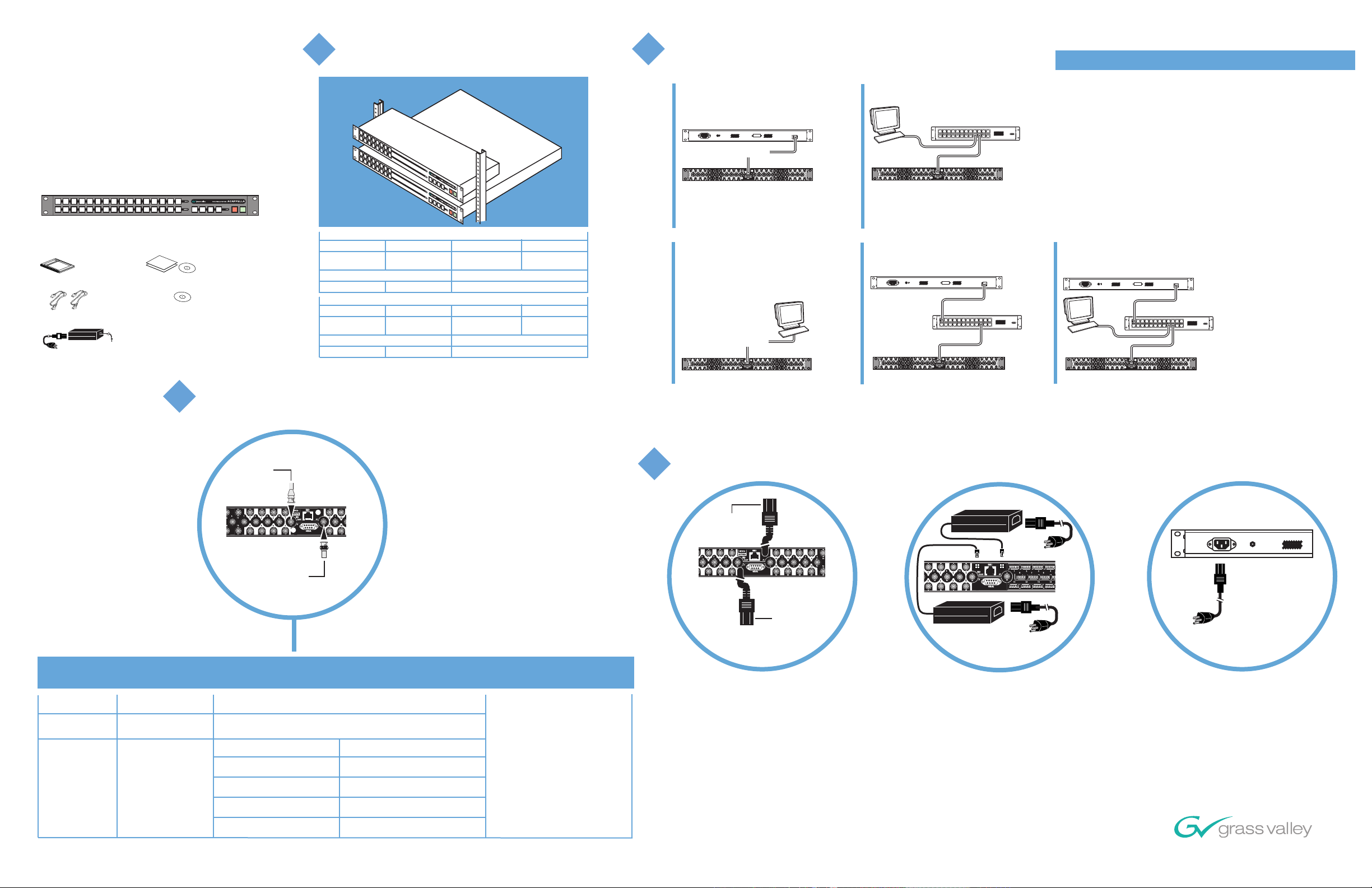
Before you begin,
unpack and identify:
Acappella Router
Instruction
Manual
Power
Cords
External Power Supply
(Analog Routers)
License
System
Software
Connect Video Reference
3
Video Reference Specifications, see Table 1
For all physical configurations
1
install Acappella in rack
shown with Remote Panel mounted above
Router
Depth Width Height Weight
392 mm
15.43 in.
Voltage Input
100-240 V AC 50-60 Hz
Depth Width Height Weight
106 mm
4.18 in.
Voltage Input
100-240 V AC 50-60 Hz
483 mm
19 in.
Remote Panel
483 mm
19 in.
44 mm
1.75 in.
Power Consumption
<40 W_
44 mm
1.75 in.
Power Consumption
<25 W_
4.89 kg.
10.78 lbs.
1.04 kg.
2.3 lbs.
Create Network
2
If Installing Router Only (no remote panels or PC) proceed to STEP 3
Remote Panel
PC and Switch
Remote Panel
Crossover Cable
Acappella
PC
Acappella
Acappella Router IP Address:
192.168.0.40
PC
Crossover Cable
Acappella
PC
Remote Panel and Switch
Remote Panel
Acappella
Ethernet Switch
Ethernet Switch
Closed Networks and Acappella Router Systems
Create closed networks between Acappella Routers,
Remote Panels, and PCs using Ethernet cables and/or
switches. A closed network is one that is kept separate
from other Local Area Networks and the Internet.
Use patch cables if you are using switches between the
routers, panels, and PCs.
It is also possible to use a crossover cable to connect an
Acappella Router directly to either a Remote Panel or a PC;
this option is only practical in very small systems.
One of the five networks shown in step 2 should work for
your facility.
Remote panel, Switch and PC
Remote Panel
Ethernet Switch
PC
Remote Panel IP Address:
Acappella
192.168.0.41
Reference
Loop
3
1
2
11
13
V
15
I
D
E
16
12
14
O
6
4
5
9
15
13
10
16
14
Table 1. Video Reference Specifications
Reference
Type *
NTSC
Color Black
PAL
Color Black
Default
Switching
middle of line 10
Switching
middle of line 6
720p/59.94 & 720p/60
TLS
Tri-Level-Sync
Switching
middle of line 7
720p/50
1080i/59.94 & 1080i/60
ENET
INPUTS
OUTPUTS
7
11
12
10
9
8
7
5
8
6
REF
1
3
LOOP
J1
2
4
SERIAL
Reference Loop
75 ohm Terminator
Horizontal Offset
(0 midpoint)
Adjustable up to +/- 30.5us
Adjustable up to +/- 31.1us
3
1
2
11
13
15
J2
16
12
14
6
4
9
10
7
5
11
15
16
7
13
12
8
14
Adjustable up to +/- 10.3us
Adjustable up to +/- 12.7us
Adjustable up to +/- 14.2us
Connect Power Cords
4
Digital
10
9
8
1
3
5
A
U
D
I
2
4
6
O
Router
Redundant
Analog
Router
Redundant PS
Remote
Panel
Power Supply
ENET
INPUTS
3
1
2
11
13
V
15
I
D
E
16
12
14
O
6
4
9
10
7
5
15
16
8
11
7
13
12
8
14
OUTPUTS
10
9
REF
1
3
5
4
6
J2
LOOP
J1
2
SERIAL
3
1
2
11
13
15
16
12
14
6
4
9
10
7
5
11
15
13
12
16
14
10
9
8
7
8
1
3
5
A
U
D
I
2
4
6
O
Power Supply
Plug into power
to activate unit
Plug into power
to activate unit
Plug into power
to activate unit
Vertical Offset
(0 midpoint)
Adjustable from -15 lines
up to +16 lines
1080i/50
1080p/24 & 1080fs/48
All Input signals and the Video Reference signal need to be in time with each other.
*
Adjustable up to +/- 17.1us
Adjustable up to +/- 18.0us
Copyright © Grass Valley
071-8364-02 October 2005
Page 2
Acappella
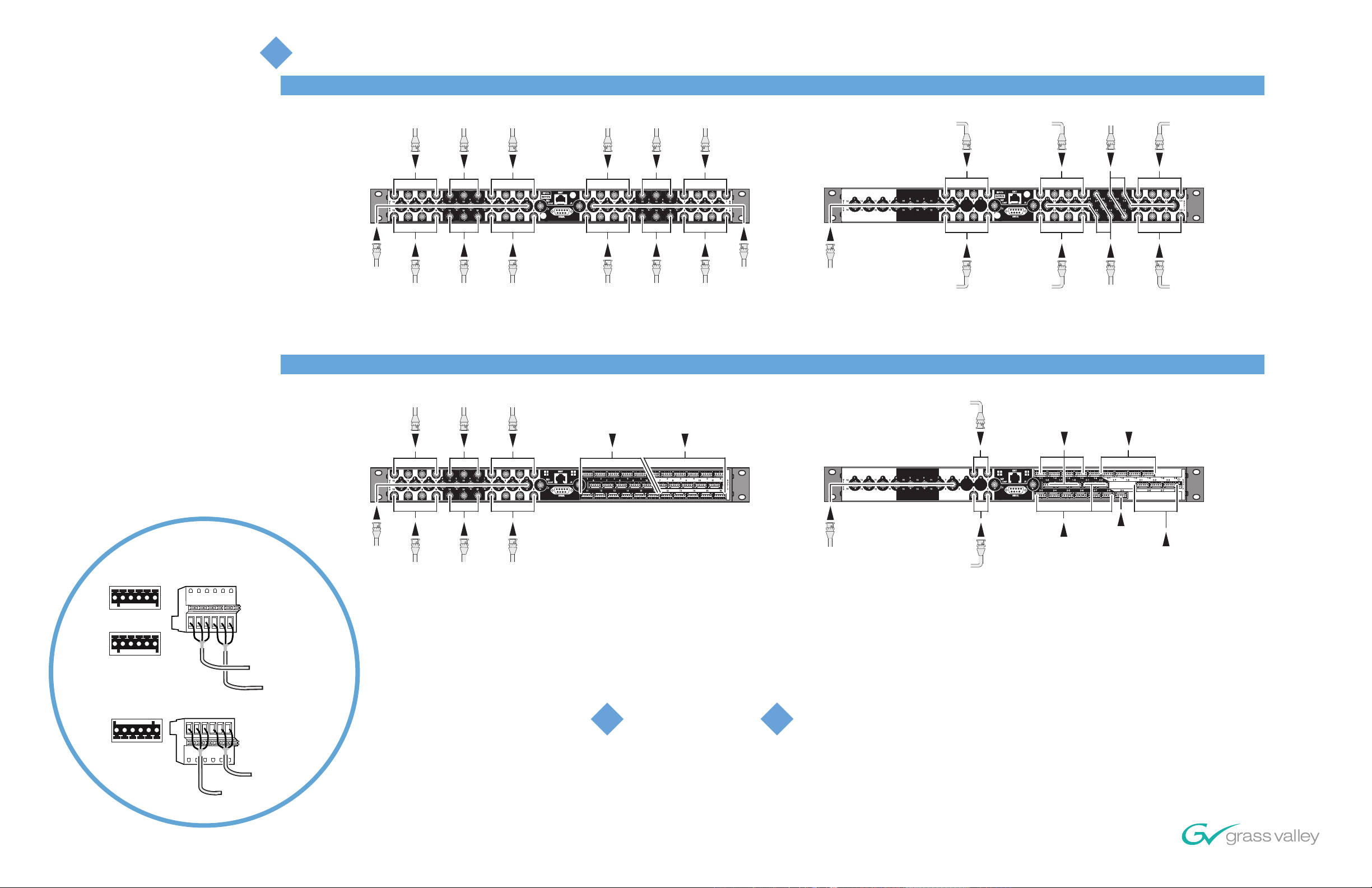
5
Cabling for Acappella Routers
Quick Start
Guide
Video
Inputs
1, 2, 3,
4, 5, 6,
7, 8, 9,
10
Video Analog and Digital
Cabling is identical.
Video
Outputs
9, 11, 13, 15
1
2
11
13
V
15
I
D
E
16
12
14
O
Video
Outputs
10, 12, 14, 16
Outputs
9, 11, 13, 15
Cabling for Acappella Digital 16 x 16 Router
Video
Outputs
1, 3, 5, 7
ENET
INPUTS
6
7
8
11
7
5
12
8
6
OUTPUTS
10
9
REF
1
3
LOOP
J1
2
4
SERIAL
Video
Outputs
2, 4, 6, 8
9, 11, 13, 15
15
J2
16
10, 12, 14, 16
Audio
Outputs
1
2
13
14
Audio
Outputs
Audio
Inputs
11, 13, 15
3
9
11
10
12
6
4
5
11
15
13
12
16
14
Audio
Inputs
12, 14, 16
3
10
11, 13, 15
4
9
15
16
12, 14, 16
Video
Inputs
5
13
14
Video
Inputs
Cabling for Acappella Analog 16 x 16 Router
Video Video Video
Inputs
11, 13, 15
Outputs
1, 3, 5, 7
Audio
Inputs
1 through 16
Outputs
1 through 16
7
7
8
Audio
Audio
Outputs
1, 3, 5, 7
9
8
5
6
Audio
Outputs
2, 4, 6, 8
Cabling for Acappella Digital 8 x 8 Dual Stereo Router
Audio Inputs
Video Outputs
1, 3, 5, 7
Audio Outputs
2-1, 2-3,
2-5, 2-7
10
1
3
A
U
D
I
2
4
O
Audio
Inputs
1, 2, 3,
4, 5, 6,
7, 8, 9,
Video Inputs
1, 2, 3,
4, 5, 6,
7, 8
Video Outputs
2, 4, 6, 8
Audio Outputs
2-2, 2-4,
2-6, 2-8
1-1, 1-2, 1-3, 1-4,
1-5, 1-6, 1-7, 1-8
Audio Inputs
2-1, 2-2, 2-3, 2-4,
2-5, 2-6, 2-7, 2-8
Audio Outputs
1-1, 1-3,
1-5, 1-7
Audio Outputs
1-2, 1-4,
1-6, 1-8
10
Cabling for Acappella Analog 8 x 4 Dual Stereo Router
Video Outputs
1, 3
Audio Inputs
1-1, 1-2, 1-3, 1-4,
1-5, 1-6, 1-7, 1-8
Audio Outputs
1-1, 1-2,
1-3, 1-4
Analog
Pinouts (balanced)
Top 2 Rows (connector right side up)
+ - G + - G
A B
+ - G + - G
Bottom Row (same connector upside down)
G - + G - +
B A
Ch A (Left)
Ch B (Right)
Ch A (Left)
Ch B (Right)
Video
Inputs
1, 2, 3,
4, 5, 6,
7, 8, 9,
10
1
2
11
13
V
15
I
D
E
16
12
14
O
Video
Outputs
10, 12, 14, 16
3
10
4
9
15
16
12, 14, 16
5
13
14
Video
Inputs
6
7
9
8
11
7
3
5
12
8
4
6
Video
Outputs
2, 4, 6, 8
ENET
10
REF
1
2
J2
LOOP
J1
SERIAL
Bottom connector row
upside down. See
Analog Pinouts at left.
Video Inputs
1, 2, 3,
4, 5, 6,
7, 8
Video Outputs
2, 4
Audio Inputs
2-1, 2-2, 2-3, 2-4,
2-5, 2-6, 2-7, 2-8
Audio Output
2-4
Audio Outputs
2-1, 2-2, 2-3
Bottom connector row
upside down. See
Analog Pinouts at left.
For Router and PC or Router, Remote Panel, and PC
Load software
6
See the Acappella Instruction Manual for more details.
www.thomsongrassvalley.com
View and modify settings
7
Copyright © Grass Valley
071-8364-02 October 2005
 Loading...