

Page 1
8995UPC/DNC/UDX
SD/HD UP/DOWN/CROSS CONVERTER
Instruction Manual
Software Version 1.3.0
071848005
MARCH 2011
Page 2

Affiliate with the N.V. KEMA in The Netherlands
CERTIFICATE
Certificate Number: 510040.001
The Quality System of:
Thomson Inc, and its worLdwide Grass Valley division affiliates DBA
GRASS VALLEY
Headquarters
400 Providence Mine Rd
Nevada City, CA 95959
United States
15655 SW Greystone Ct.
Beaverton, OR 97006
United States
10 Presidential Way
Suite 300
Woburn, MA 01801
United States
Kapittelweg 10
4827 HG Breda
The Nederlands
7140 Baymeadows Way
Ste 101
Jacksonville, FL 32256
United States
2300 So. Decker Lake Blvd.
Salt Lake City, UT 84119
United States
Rue du Clos Courtel
CS 31719
35517 Cesson-Sevigné Cedex
France
1 rue de l’Hautil
Z.I. des Boutries BP 150
78702 Conflans-Sainte
Honorine Cedex
France
Technopole Brest-Iroise
Site de la Pointe du Diable
CS 73808
29238 Brest Cedex 3
France
40 Rue de Bray
2 Rue des Landelles
35510 Cesson Sevigné
France
Spinnereistrasse 5
CH-5300 Turgi
Switzerland
Brunnenweg 9
D-64331 Weiterstadt
Germany
Carl-Benz-Strasse 6-8
67105 Schifferstadt
Germany
Including its implementation, meets the requirements of the standard:
ISO 9001:2008
Scope:
The design, manufacture and support of video and audio hardware and software products and
related systems
.
This Certificate is valid until: June 14, 2012
This Certificate is valid as of: June 14, 2009
Certified for the first time: June 14, 2000
H. Pierre Sallé
President
KEMA-Registered Quality
The method of operation for quality certification is defined in the KEMA General Terms
And Conditions For Quality And Environmental Management Systems Certifications.
Integral publication of this certificate is allowed.
KEMA-Registered Quality, Inc.
4377 County Line Road
Chalfont, PA 18914
Ph: (215)997-4519
Fax: (215)997-3809
CRT 001 073004
Accredited By:
ANAB
Page 3

8995UPC/DNC/UDX
SD/HD UP/DOWN/CROSS CONVERTER
Instruction Manual
Software Version 1.3.0
071848005
MARCH 2011
Page 4
Contacting Grass Valley
International
Support Centers
Local Support
Centers
(available
during normal
business hours)
France
24 x 7
Australia and New Zealand: +61 1300 721 495 Central/South America: +55 11 5509 3443
Middle East: +971 4 299 64 40 Near East and Africa: +800 8080 2020 or +33 1 48 25 20 20
Europe
+800 8080 2020 or +33 1 48 25 20 20
Hong Kong, Taiwan, Korea, Macau: +852 2531 3058 Indian Subcontinent: +91 22 24933476
Asia
Southeast Asia/Malaysia: +603 7805 3884 Southeast Asia/Singapore: +65 6379 1313
China: +861 0660 159 450 Japan: +81 3 5484 6868
Belarus, Russia, Tadzikistan, Ukraine, Uzbekistan: +7 095 2580924 225 Switzerland: +41 1 487 80 02
S. Europe/Italy-Roma: +39 06 87 20 35 28 -Milan: +39 02 48 41 46 58 S. Europe/Spain: +34 91 512 03 50
Benelux/Belgium: +32 (0) 2 334 90 30 Benelux/Netherlands: +31 (0) 35 62 38 42 1 N. Europe: +45 45 96 88 70
Germany, Austria, Eastern Europe: +49 6150 104 444 UK, Ireland, Israel: +44 118 923 0499
Copyright © Grass Valley USA, LLC. All rights reserved.
This product may be covered by one or more U.S. and foreign patents.
United States/Canada
24 x 7
+1 800 547 8949 or +1 530 478 4148
Grass Valley Web Site
The www.grassvalley.com web site offers the following:
Online User Documentation — Current versions of product catalogs, brochures,
data sheets, ordering guides, planning guides, manuals, and release notes
in .pdf format can be downloaded.
FAQ Database — Solutions to problems and troubleshooting efforts can be
found by searching our Frequently Asked Questions (FAQ) database.
Software Downloads — Download software updates, drivers, and patches.
4 8995UPC/DNC/UDX — Instruction Manual
Page 5

Contents
Preface. . . . . . . . . . . . . . . . . . . . . . . . . . . . . . . . . . . . . . . . . . . . . . . . . . . . . . . . . . . . . . . . . . . . . 7
8995UPC/DNC/UDX Up/Down/Cross Converter Modules . . . . . . . . . . . . . . . 9
About This Manual . . . . . . . . . . . . . . . . . . . . . . . . . . . . . . . . . . . . . . . . . . . . . . . . . . . . . 7
Introduction . . . . . . . . . . . . . . . . . . . . . . . . . . . . . . . . . . . . . . . . . . . . . . . . . . . . . . . . . . . 9
8995UDX Module. . . . . . . . . . . . . . . . . . . . . . . . . . . . . . . . . . . . . . . . . . . . . . . . . . 10
8995UPC Module . . . . . . . . . . . . . . . . . . . . . . . . . . . . . . . . . . . . . . . . . . . . . . . . . . 10
8995DNC Module . . . . . . . . . . . . . . . . . . . . . . . . . . . . . . . . . . . . . . . . . . . . . . . . . 10
System Requirements . . . . . . . . . . . . . . . . . . . . . . . . . . . . . . . . . . . . . . . . . . . . . . . . . . 11
Installation . . . . . . . . . . . . . . . . . . . . . . . . . . . . . . . . . . . . . . . . . . . . . . . . . . . . . . . . . . . 12
Module Placement in the GeckoFlex Frame . . . . . . . . . . . . . . . . . . . . . . . . . . . . . 12
Module Installation Precautions . . . . . . . . . . . . . . . . . . . . . . . . . . . . . . . . . . . . . 13
8995 Module Placement For Genlock Timing . . . . . . . . . . . . . . . . . . . . . . . . . . . . 14
Rear Module Installation . . . . . . . . . . . . . . . . . . . . . . . . . . . . . . . . . . . . . . . . . . . 15
Genlock Submodule Installation . . . . . . . . . . . . . . . . . . . . . . . . . . . . . . . . . . . . . 16
Frame Bus Jumpering . . . . . . . . . . . . . . . . . . . . . . . . . . . . . . . . . . . . . . . . . . . . . . 17
Front Module Installation. . . . . . . . . . . . . . . . . . . . . . . . . . . . . . . . . . . . . . . . . . . 18
Optional Fiber Optics Submodule Installation . . . . . . . . . . . . . . . . . . . . . . . . . 19
Fiber Optic Cleaning Requirement . . . . . . . . . . . . . . . . . . . . . . . . . . . . . . . . . . . 19
Cabling . . . . . . . . . . . . . . . . . . . . . . . . . . . . . . . . . . . . . . . . . . . . . . . . . . . . . . . . . . . . 21
Genlock Loop . . . . . . . . . . . . . . . . . . . . . . . . . . . . . . . . . . . . . . . . . . . . . . . . . . . . . 21
Video Input . . . . . . . . . . . . . . . . . . . . . . . . . . . . . . . . . . . . . . . . . . . . . . . . . . . . . . . 21
Video Outputs . . . . . . . . . . . . . . . . . . . . . . . . . . . . . . . . . . . . . . . . . . . . . . . . . . . . 22
Reclocked Video Output. . . . . . . . . . . . . . . . . . . . . . . . . . . . . . . . . . . . . . . . . . . . 22
Auto Tracking Output. . . . . . . . . . . . . . . . . . . . . . . . . . . . . . . . . . . . . . . . . . . . . . 22
Set Fan Speed to Maximum . . . . . . . . . . . . . . . . . . . . . . . . . . . . . . . . . . . . . . . . . . . . . 23
Power Up . . . . . . . . . . . . . . . . . . . . . . . . . . . . . . . . . . . . . . . . . . . . . . . . . . . . . . . . . . . . 24
Operation Indicator LEDs . . . . . . . . . . . . . . . . . . . . . . . . . . . . . . . . . . . . . . . . . . . . 24
Configuration. . . . . . . . . . . . . . . . . . . . . . . . . . . . . . . . . . . . . . . . . . . . . . . . . . . . . . . . . 26
Configuration Summary. . . . . . . . . . . . . . . . . . . . . . . . . . . . . . . . . . . . . . . . . . . . . . 26
Video Input Selection . . . . . . . . . . . . . . . . . . . . . . . . . . . . . . . . . . . . . . . . . . . . . . 26
Video Timing and Loss of Signal Controls . . . . . . . . . . . . . . . . . . . . . . . . . . . . 26
Signal Conversion . . . . . . . . . . . . . . . . . . . . . . . . . . . . . . . . . . . . . . . . . . . . . . . . . 27
Color Correction. . . . . . . . . . . . . . . . . . . . . . . . . . . . . . . . . . . . . . . . . . . . . . . . . . . 29
Video Processing Adjustments . . . . . . . . . . . . . . . . . . . . . . . . . . . . . . . . . . . . . . 29
Aspect Ratio Controls . . . . . . . . . . . . . . . . . . . . . . . . . . . . . . . . . . . . . . . . . . . . . . 30
Transcoding . . . . . . . . . . . . . . . . . . . . . . . . . . . . . . . . . . . . . . . . . . . . . . . . . . . . . . 33
Audio Processing and Configuration . . . . . . . . . . . . . . . . . . . . . . . . . . . . . . . . . 33
Genlock Controls . . . . . . . . . . . . . . . . . . . . . . . . . . . . . . . . . . . . . . . . . . . . . . . . . . 33
User Settings . . . . . . . . . . . . . . . . . . . . . . . . . . . . . . . . . . . . . . . . . . . . . . . . . . . . . . 33
Fiber Optic Outputs. . . . . . . . . . . . . . . . . . . . . . . . . . . . . . . . . . . . . . . . . . . . . . . . 33
Remote Configuration and Monitoring . . . . . . . . . . . . . . . . . . . . . . . . . . . . . . . . . 34
Local/Remote Jumper. . . . . . . . . . . . . . . . . . . . . . . . . . . . . . . . . . . . . . . . . . . . . . 34
8900NET Module Information . . . . . . . . . . . . . . . . . . . . . . . . . . . . . . . . . . . . . . . 34
8995UPC/DNC/UDX — Instruction Manual 5
Page 6

Contents
Newton Control Panel Configuration . . . . . . . . . . . . . . . . . . . . . . . . . . . . . . . . 35
Web Browser Interface . . . . . . . . . . . . . . . . . . . . . . . . . . . . . . . . . . . . . . . . . . . . . 36
Status Web Page . . . . . . . . . . . . . . . . . . . . . . . . . . . . . . . . . . . . . . . . . . . . . . . . . . 43
I/O Config Web Page . . . . . . . . . . . . . . . . . . . . . . . . . . . . . . . . . . . . . . . . . . . . . . 46
System Config Web Page . . . . . . . . . . . . . . . . . . . . . . . . . . . . . . . . . . . . . . . . . . . 48
Functional View Web Page . . . . . . . . . . . . . . . . . . . . . . . . . . . . . . . . . . . . . . . . . 53
Video Input Web Page . . . . . . . . . . . . . . . . . . . . . . . . . . . . . . . . . . . . . . . . . . . . . 54
Frame Sync Web Page . . . . . . . . . . . . . . . . . . . . . . . . . . . . . . . . . . . . . . . . . . . . . 55
Color Correction Web Page . . . . . . . . . . . . . . . . . . . . . . . . . . . . . . . . . . . . . . . . . 62
Video Proc Web Page . . . . . . . . . . . . . . . . . . . . . . . . . . . . . . . . . . . . . . . . . . . . . . 63
Transcoding Web Page. . . . . . . . . . . . . . . . . . . . . . . . . . . . . . . . . . . . . . . . . . . . . 66
CC Transcoding. . . . . . . . . . . . . . . . . . . . . . . . . . . . . . . . . . . . . . . . . . . . . . . . . . . 66
VITC Transcoding. . . . . . . . . . . . . . . . . . . . . . . . . . . . . . . . . . . . . . . . . . . . . . . . . 71
Aspect Ratio Web Page . . . . . . . . . . . . . . . . . . . . . . . . . . . . . . . . . . . . . . . . . . . . 73
Video Out Web Page. . . . . . . . . . . . . . . . . . . . . . . . . . . . . . . . . . . . . . . . . . . . . . . 78
Audio Input Status Web Page . . . . . . . . . . . . . . . . . . . . . . . . . . . . . . . . . . . . . . . 79
Audio Delay Web Page . . . . . . . . . . . . . . . . . . . . . . . . . . . . . . . . . . . . . . . . . . . . 80
Audio Gain Web Page . . . . . . . . . . . . . . . . . . . . . . . . . . . . . . . . . . . . . . . . . . . . . 82
Audio Channel Pairing Web Page . . . . . . . . . . . . . . . . . . . . . . . . . . . . . . . . . . . 84
Audio Proc Web Page. . . . . . . . . . . . . . . . . . . . . . . . . . . . . . . . . . . . . . . . . . . . . . 86
Genlock Web Page . . . . . . . . . . . . . . . . . . . . . . . . . . . . . . . . . . . . . . . . . . . . . . . . 88
User Settings Web Page . . . . . . . . . . . . . . . . . . . . . . . . . . . . . . . . . . . . . . . . . . . . 92
Slot Config Web Page . . . . . . . . . . . . . . . . . . . . . . . . . . . . . . . . . . . . . . . . . . . . . . 95
Software Updating . . . . . . . . . . . . . . . . . . . . . . . . . . . . . . . . . . . . . . . . . . . . . . . . . . . . 98
Specifications. . . . . . . . . . . . . . . . . . . . . . . . . . . . . . . . . . . . . . . . . . . . . . . . . . . . . . . . . 99
Status Monitoring. . . . . . . . . . . . . . . . . . . . . . . . . . . . . . . . . . . . . . . . . . . . . . . . . . . . 106
External Frame Alarm . . . . . . . . . . . . . . . . . . . . . . . . . . . . . . . . . . . . . . . . . . . . . . 106
LED Reporting. . . . . . . . . . . . . . . . . . . . . . . . . . . . . . . . . . . . . . . . . . . . . . . . . . . . . 107
Web Browser Interface. . . . . . . . . . . . . . . . . . . . . . . . . . . . . . . . . . . . . . . . . . . . . . 107
SNMP Reporting. . . . . . . . . . . . . . . . . . . . . . . . . . . . . . . . . . . . . . . . . . . . . . . . . . . 107
Service . . . . . . . . . . . . . . . . . . . . . . . . . . . . . . . . . . . . . . . . . . . . . . . . . . . . . . . . . . . . . 108
Power-Up Diagnostic Failure . . . . . . . . . . . . . . . . . . . . . . . . . . . . . . . . . . . . . . . . 108
Troubleshooting . . . . . . . . . . . . . . . . . . . . . . . . . . . . . . . . . . . . . . . . . . . . . . . . . . . 108
Electronic Circuit Breaker . . . . . . . . . . . . . . . . . . . . . . . . . . . . . . . . . . . . . . . . . 108
Module Repair. . . . . . . . . . . . . . . . . . . . . . . . . . . . . . . . . . . . . . . . . . . . . . . . . . . . . 108
Functional Description . . . . . . . . . . . . . . . . . . . . . . . . . . . . . . . . . . . . . . . . . . . . . . . 109
Configuration Summary Table. . . . . . . . . . . . . . . . . . . . . . . . . . . . . . . . . . . . . . . . . 111
Active Format Description. . . . . . . . . . . . . . . . . . . . . . . . . . . . . . . . . . . . . . . . . . . . . 117
AFD Tables . . . . . . . . . . . . . . . . . . . . . . . . . . . . . . . . . . . . . . . . . . . . . . . . . . . . . . . . . 118
Notes on AFD . . . . . . . . . . . . . . . . . . . . . . . . . . . . . . . . . . . . . . . . . . . . . . . . . . . . . . . 118
How to Use the AFD Conversion Tables . . . . . . . . . . . . . . . . . . . . . . . . . . . . . . . . 119
AFD Code Definitions . . . . . . . . . . . . . . . . . . . . . . . . . . . . . . . . . . . . . . . . . . . . . . 123
AFD Definitions For 4:3 Coded Frames. . . . . . . . . . . . . . . . . . . . . . . . . . . . . . 123
AFD Codes For 16:9 Coded Frames . . . . . . . . . . . . . . . . . . . . . . . . . . . . . . . . . 125
AFD Tables – Up Conversion . . . . . . . . . . . . . . . . . . . . . . . . . . . . . . . . . . . . . . . . 127
AFD Tables – Down Conversion . . . . . . . . . . . . . . . . . . . . . . . . . . . . . . . . . . . . . 132
Index. . . . . . . . . . . . . . . . . . . . . . . . . . . . . . . . . . . . . . . . . . . . . . . . . . . . . . . . . . . . . . . . . . . . . 137
6 8995UPC/DNC/UDX — Instruction Manual
Page 7

Preface
About This Manual
This manual describes the features of a specific 8900 module in the
GeckoFlex Signal Processing System family. As part of this module family,
it is subject to Safety and Regulatory Compliance described in the
GeckoFlex 8900 Series frame documentation (see the GeckoFlex Frames
8900FX/FF/FFN Signal Processing System Instruction Manual).
All Modular product documentation can be found on-line in PDF format at
this link:
www.grassvalley.com/docs/modular
8995UPC/DNC/UDX — Instruction Manual 7
Page 8

Preface
8 8995UPC/DNC/UDX — Instruction Manual
Page 9

8995UPC/DNC/UDX Up/Down/Cross Converter Modules
Introduction
This manual covers installation, configuration, and operation for the
8995UPC Up Converter, 8995DNC Down Converter, and 8995UDX
Up/Down/Cross Converter modules for the GeckoFlex frame.
The 8995 modules provide up/down/cross conversion between broadcast
quality SD and HD video. An optional Genlock submodule can be installed
for external reference timing for environments requiring video signals to be
synchronized with other video sources and processed for video quality.
The following features are available with this module series.
• Two module set including a hot-swappable front and rear module. The
rear module requires two rear slots.
• Up to five 8995 modules in the same 2 RU GeckoFlex frame.
• An optional Genlock submodule mounted on the 8995 circuit board
accepts an external reference (NTSC/PAL color black or Tri-Level Sync)
and manages local and frame bus reference timing to the module.
• Fiber-ready front module accepts a fiber optic submodule option for
optical input/output interfaces for all models. Refer to Tab le 1 on
page 19 for the submodules available.
• Frame Sync (with Genlock submodule from two independent frame
buses or for local reference) and Delay mode.
• Full featured video proc amp functions including RGB and component
color controls, video gain, Y/C clip controls, chroma gain, phase (Hue)
and black level control, color space conversion (ITU 601, ITU 709), and
Cadence control for setting 3:2 pulldown for video from film.
• Aspect ratio control including mode selection, alignment, top crop and
matte color along with Active Format Description (AFD) input and
output status reporting and enabling and disabling controls.
8995UPC/DNC/UDX — Instruction Manual 9
Page 10

Introduction
• Edge enhancement and pixel-level motion adaptive conversion for
superb picture quality.
• Color correction controls for RGB gain and offset and gamma settings.
• Powerful handling of embedded audio for channel level and Dolby E
stream routing.
• PCM audio processing including audio status reporting, delay, gain,
channel pairing, and audio processing controls. Processed audio is then
re-embedded into output video stream.
• One auto-tracking output to allow synchronization of audio modules to
the Genlock reference.
• VITC time code SD to HD and HD to SD translation supported for
same-frame rate (59.94 Hz) or Closed Caption SD to HD or HD to SD
translation at same frame rate (59.94 Hz), or output line select for VITC
and Closed Caption.
• Minimum delay (1 frame) for low latency live applications all critical
format conversions.
• SNMP and product health monitoring is supported through the
8900NET module with applications such as NetCentral.
• Software updating using the NetConfig Networking application
and/or microSD card.
8995UDX Module
The 8995UDX provides the full spectrum of up, down, and cross conversion with all of the functionality listed above. Refer to Tab le 3 on page 28
for a video conversion summary diagram.
8995UPC Module
The 8995UPC is fully featured with 8995 series functionality described
above. This module up converts SD video to high quality HD video. Refer
to
Tab le 4 on page 28 for a video conversion summary diagram.
8995DNC Module
The 8995DNC is fully featured with 8995 series functionality described
above. This module down converts HD video to high quality SD video.
Refer to
Tab le 5 on page 29 for a video conversion summary diagram.
10 8995UPC/DNC/UDX — Instruction Manual
Page 11

System Requirements
The following system requirements are necessary for proper operation of
the 8995 Series modules:
• 8995 module operation requires the presence of an 8900NET Network
Interface module in an 8900FFN GeckoFlex frame for configuration.
There are no local front edge configuration controls for this module.
When using the web browser interface, the latest version of Internet
Explorer is the recommended application. Other web browsers may
cause unexpected results.
The latest version of 8900NET (Net Card) software must be at 4.3.0 for
proper operation. Check the software version of your 8900NET module
by navigating to the Frame Status web page (
noting the software version given below the frame graphic. Check the
Grass Valley ftp server at this link for the latest 8900NET release:
ftp://ftp.grassvalley.com/modular/8900/8900net/v4.3.0/
• Fans in the front cover must be set at maximum speed. Refer to Set Fan
Speed to Maximum on page 23.
System Requirements
Figure 16 on page 37) and
• 8995 Series release 1.2.0 or later requires version 8 Firmware and
version 1 Hardware be installed on the 8900GEN-SM Genlock Submodule if present on any modules. Firmware can be updated with the
software update for version 1.2.0 as described in the Release Notes that
accompany the version 1.2.0 software release.
To check the version of the 8900GEN-SM submodule, link to the
Genlock web page and note the
reported in the web page header as shown in
For software updating information, refer to Software Updating on page 98.
Firmware Version and Hardware Revision
Figure 54 on page 89.
8995UPC/DNC/UDX — Instruction Manual 11
Page 12
Installation
Installation
The 8995 models consists of a front and rear module set that can only be
installed in a GeckoFlex frame. An optional fiber optic submodule is also
available for providing fiber inputs or outputs depending on the type of
submodule installed. Installation of the 8995 module set is a process of:
1. Determining the placement of the 8995 module based on genlock
timing configuration if required,
2. Placing the 8900UDX-R rear module in a rear frame slot (this rear
module requires two adjacent rear slot spaces),
3. Installing the Genlock submodule option on the front module if used,
4. Placing the front module in the corresponding front slot,
5. Installing the optional SFP Fiber Optic submodule in the rear module,
6. Cabling the signal ports, and
7. Setting front cover fan speed on 8900NET module to maximum.
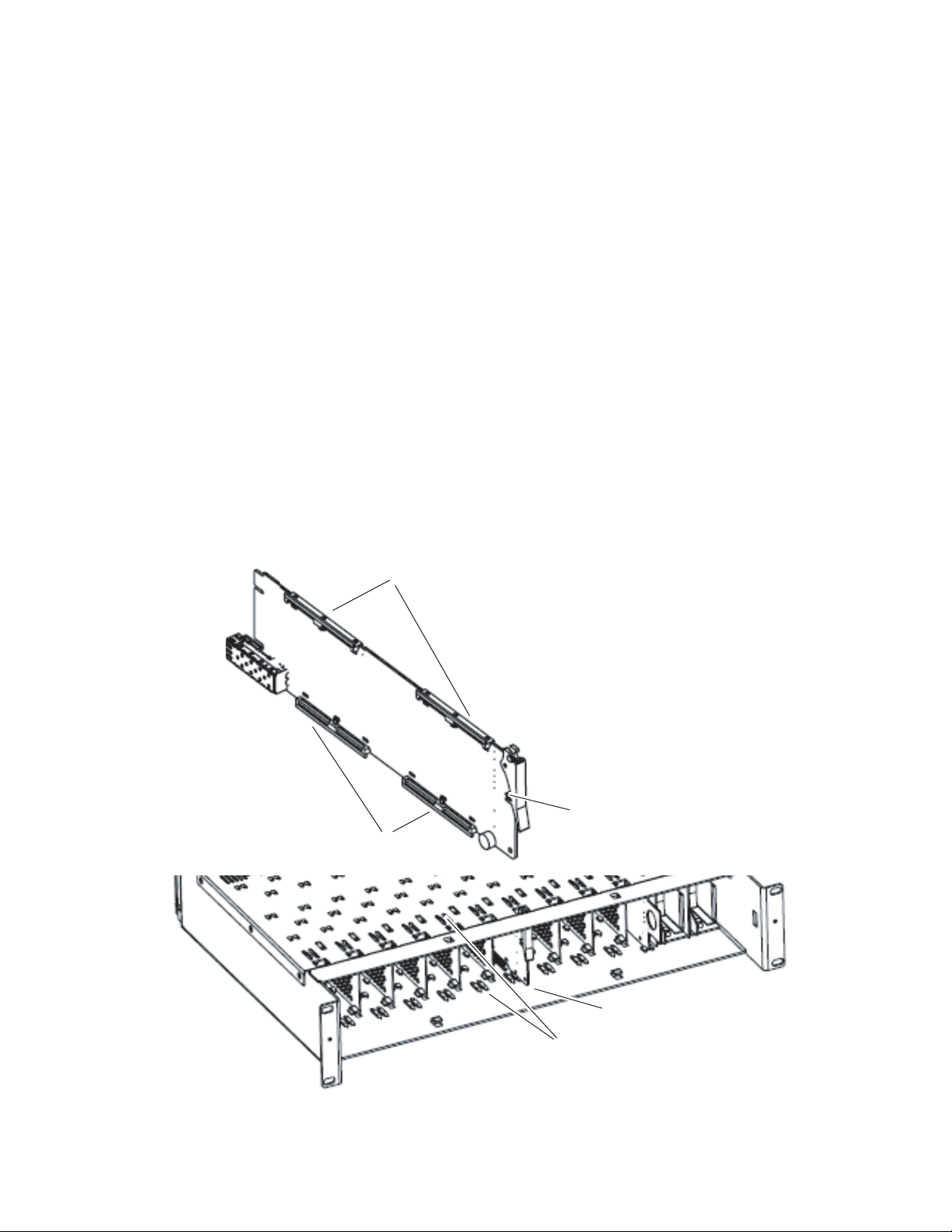
Module Placement in the GeckoFlex Frame
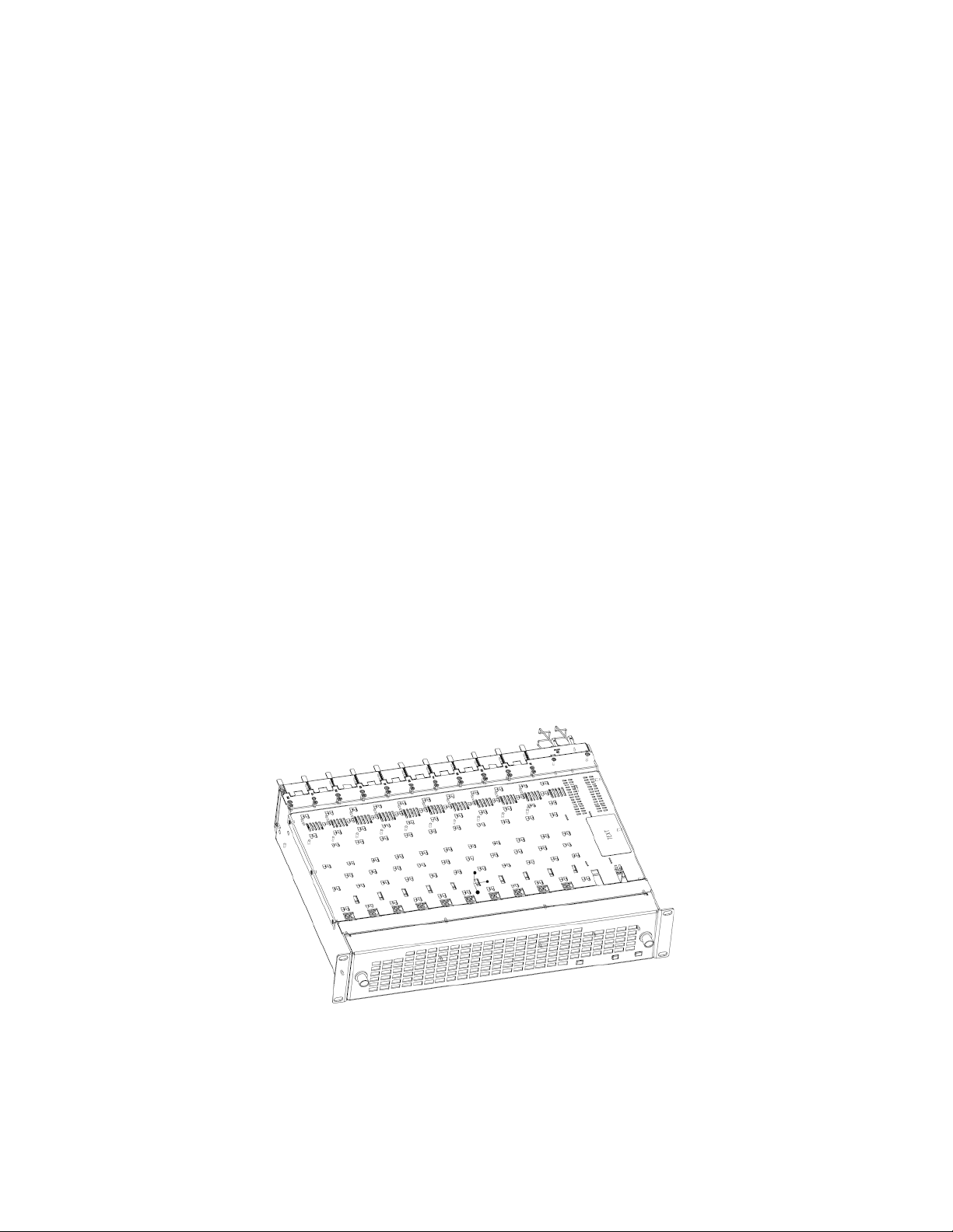
There are ten front and rear cell locations in the 2 RU GeckoFlex frame
(
Figure 1) to accommodate either audio, analog and digital video modules.
The 8995 module set uses the 8900UDX-R rear module that requires two
adjacent slots, allowing five 8995 modules per frame.
Figure 1. GeckoFlex Frame
12 8995UPC/DNC/UDX — Instruction Manual
Page 13

Module Installation Precautions
Please read and follow the precautions listed below before installing the
front and rear modules and any fiber optic option submodules:
• Use standard anti-static procedures during installation. As modules
can be installed or removed when the GeckoFlex frame is powered up,
before removing the cover, please use an anti-static bracelet tied to a
metal part of the frame.
• Install the rear module first, the 8900GEN-SM submodule on the front
module (if used), the front module, then the optical submodule option
(if used).
• When installing or removing a rear module, loosen or tighten the
screws holding the retainer clips to the frame manually with the
retainer clip tool provided inside the front cover of the frame or use a
2 mm (5/64”) hex screwdriver. Please do not use an electric screwdriver.
Note On newer 751- version GeckoFlex frames, a Rear Retainer Clip removal tool
and 2 extra retainer clips and screws for installing them are provided on the
inside of the frame cover.
Installation
• Make every effort to leave the screws holding the retainer clips in place
(do not remove them completely). They are very small and can easily
drop into other equipment causing a shorting hazard. (Two turns of the
screw should be enough to loosen the screws, 3 turns or more will
remove it.)
• When installing a rear module, tighten the screws on the retainer clips
just until snug. Do not apply more force than is necessary to seat the
rear module. The retainer clip screw torque specification is given in the
Mechanical specifications in Table 9 on page 99.
• If using a fiber optic submodule, handle it carefully, use anti-static precautions, and read the Fiber Optic Cleaning Requirement on page 19
before cabling.
8995UPC/DNC/UDX — Instruction Manual 13
Page 14

Installation
8995 Module Placement For Genlock Timing
Before installing the 8995 module, you will first need to determine if and
how you want to use a genlock reference or the available frame reference
buses. The genlock timing from an 8900GEN-SM submodule can be uti
lized in several ways. Refer to the 8900GEN-SM GeckoFlex Genlock Instruc-
tion Manual available online for a complete overview of using the genlock
reference.
This as well as all other modular product manuals are available online at
the following URL on the Grass Valley web site:
http://www.grassvalley.com/docs/modular
In addition to the capability of providing a local external reference to this
specific 8995 module with an 8900GEN-SM submodule installed, slots 1
and 3 of the Gecko
an independent frame bus reference transmitted from the 8900GEN-SM
submodule mounted on an 8995 module (or other GeckoFlex module with
this capability) configured for this purpose. The external reference con
nected to the corresponding Genlock Loop BNCs can be distributed to
other modules in the frame that accept a genlock reference.
Flex frame have been specifically designed to distribute
-
-
If another 8995 module has already been configured and installed for frame
bus distribution, you may configure this module’s output timing to lock to
the Frame Bus 1 or Frame Bus 2 reference from the other 8995 module. In
this case, the 8995 does not require the use of an additional 8900GEN-SM
submodule.
The use of the genlock reference is determined by the setting of the Output
Timing on the System Config web page of the module and module place
ment in the frame and jumper configuration as summarized below.
• Local Reference – the 8995 with an 8900GEN-SM submodule can have
a local external reference connected to one of the corresponding
Genlock Loop BNCs. This external timing reference will be fed to this
specific 8995 module only.
• Frame Reference 1 or 2 – when an 8995 with an 8900GEN-SM submodule is installed in slot 1 and/or slot 3, a frame timing bus can be
enabled to distribute the external reference connected to the corresponding Genlock Loop BNCs on the rear module to all modules in the
frame that can accept a genlock reference. slot 1 provides Frame Bus 1
and slot 3 provides Frame Bus 2.
• Input Video – when no 8900GEN-SM submodule is installed on the
8995, the Output Timing can be set to Input so the output timing will
follow the input to the module.
-
14 8995UPC/DNC/UDX — Instruction Manual
Page 15
Rear Module Installation
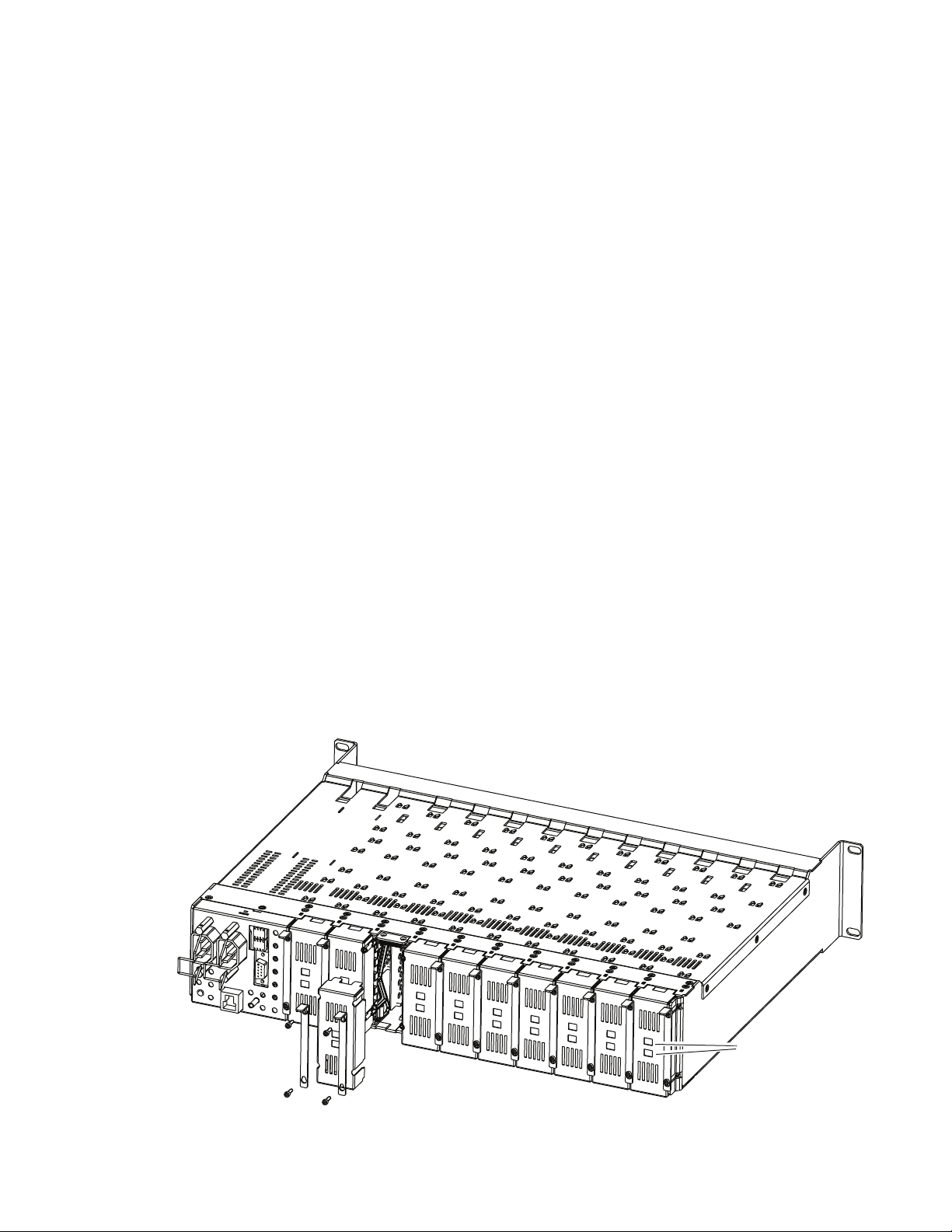
To install the rear module, refer to Figure 2 and the instructions below:
1. To remove a blank rear adapter cover (or a rear module already
present), manually loosen the two screws holding each retainer clip on
the rear adapter cover or rear module to the frame with the retainer clip
tool provided inside the front cover of the frame (newer model frames
only) or a 2
Note To remove a rear module already installed, follow the same steps. It is helpful
1. After loosening the retainer clip screws, pull up on each retainer and
completely remove it, leaving the screws in place.
2. Remove the blank rear adapter cover by inserting needlenose pliers
into the slots in the blank cover and pulling it off.
3. Insert the rear module into the empty slot, guiding it carefully.
4. Replace each retainer clip over the two screws on both sides of the
module and push down to seat the retainer clip.
mm (5/64”) hex screwdriver. Do not remove the screws.
to first remove the front module so the rear can be pulled out more easily.
Installation
5. Tighten the two screws on each retainer clip just until they come into
contract with the retainer clip then tighten about a 1/4 turn more. The
retainer clips should not bend or be bowed. The rear retainer clip screw
torque specification is 4-5 inch-lb/0.45-0.6Nm).
Note All unused rear slots in a GeckoFlex frame should have a blank rear adapter
cover installed.
Figure 2. Installing Rear Module (751- Version Frame)
8444_23r0
Use retainer clip or
needlenose pliers
to pull out blank after
removing retainer clips
8995UPC/DNC/UDX — Instruction Manual 15
Page 16
Installation
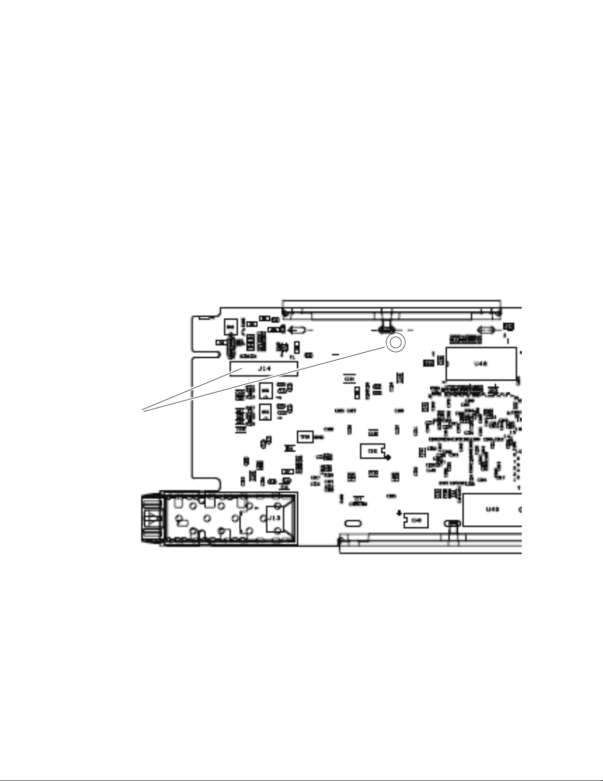
8431_05
Install Genlock submodule
on back of circuit board.
Center submodule connector J1
over front module connector J14
and snap in place. From top side
of module, tighten the screw provided
to the standoff on the circuit board.
8480_04r1
Genlock Submodule Installation
The Genlock submodule will ship in a separate package, not installed on
the front module.
To install a Genlock submodule, follow these steps:
1. Locate the Genlock connector J14, on the back side of the 8995 circuit
board (
2. Line up the connector on the submodule, J1, with J14 on the front
module and snap the submodule into place making sure the holes in
each circuit board line up.
3. To hold the submodule in place, attach the screw provided from the
bottom of the front module to the standoff on the submodule circuit
board.
Figure 3. Installing Genlock Submodule
Figure 3).
16 8995UPC/DNC/UDX — Instruction Manual
Page 17
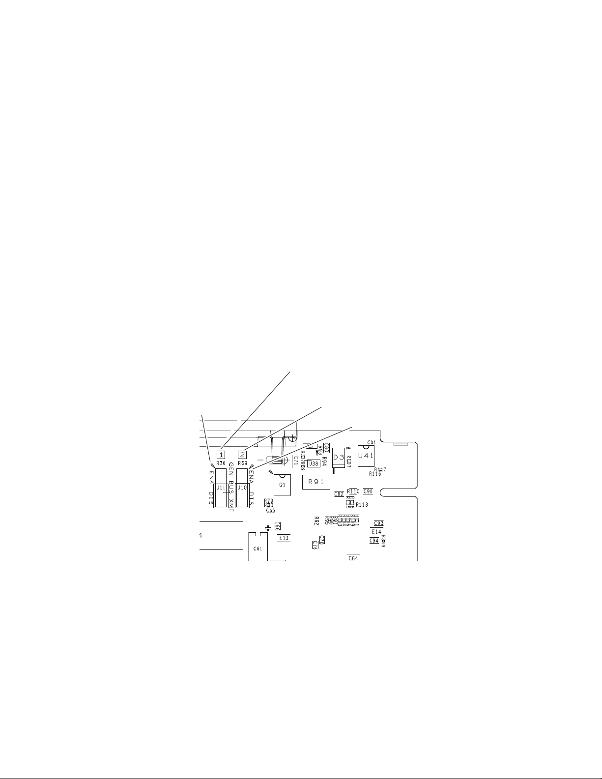
Frame Bus Jumpering
If you will be using this 8995 module to distribute reference Frame Bus 1
(slot 1) or Frame Bus 2 (slot 3), you must set a jumper on the front module
circuit board for this purpose before installing the module (
• Frame Bus 1 – to transmit the reference connected to one of the Genlock
Loop BNCs on the corresponding rear module on Frame Bus 1, set
jumper J11 to
the frame and configured on the Genlock web page (see Genlock Web
Page on page 88) for
• Frame Bus 2 – to transmit the reference connected to one of the Genlock
Loop BNCs on the corresponding rear module on Frame Bus 2, set
jumper J10 to
the frame and configured on the Genlock web page (see Genlock Web
Page on page 88) for
Note Both jumpers may be enabled. The module in slot 1 will only read the status
of jumper, J11. The module in slot 3 will only read the status of jumper, J10.
Installation
Figure 4).
ENA (pins 1-2). This module must be installed in slot 1 of
Auto in the Drive Frame Reference Bus pulldown.
ENA (pins 1-2). This module must be installed in slot 3 of
Auto in the Drive Frame Reference Bus pulldown.
Figure 4. Setting Frame Bus Jumpers
For Frame Bus 1 distribution, set
GEN LOCK BUS XMT jumper, J11
Pins 1-2 (ENA) or pins 2-3 (DIS).
Pin 1
For Frame Bus 2 distribution, set
GENLOCK BUS XMT jumper, J10
Pins 1-2 (ENA) or pins 2-3 (DIS).
Pin 1
8480_03r1
8995UPC/DNC/UDX — Instruction Manual 17
Page 18
Installation
8431_07r1
Slide top and bottom card carriers on module
over top and bottom guides on right of slot.
Module installed
Locking Pin
Card Carriers
Card Carriers
Front Module Side View
Front Module Installation
After installing the rear module (and Genlock submodule on the front
module if required), install the front module as follows:
Note If using a fiber optic submodule, install it through the rear module according
to Optional Fiber Optics Submodule Installation on page 19.
1. Remove the front cover of the frame if required.
2. Locate the corresponding front slot.
3. Insert the front module so that the plastic card guides on the module
top and bottom edges go over the upper and lower raised rail guides on
the right of the top and bottom of the slot(
4. Carefully slide the module into the rear connector.
5. Lock the front module ejector tab into the locking pin.
Note Before removing the front module, first remove the Fiber Optic submodule if
present, from the rear module.
Figure 5).
Figure 5. Front Module Installation
18 8995UPC/DNC/UDX — Instruction Manual
Page 19

Optional Fiber Optics Submodule Installation
After the front and rear modules have been installed, install the SFP Fiber
Optic submodule option if being used into the rear module metal cage
labeled FIBER (
and may be installed or removed with power applied to the module.
CAUTION The Fiber Optic submodule is static sensitive. Use static handling precautions
when installing or removing the submodule. Fiber connections must be
cleaned before installing or cabling as described in Fiber Optic Cleaning
Requirement below.
Refer to Tab le 1 for the correct model of submodule to use with different
software versions.
Table 1. Fiber Optic Submodule Summary
Submodule Type SW1.2.4 and later SW 1.2.1 and earlier
SFP-13103G-M1DRX Dual Receiver X –
SFP-13103G-M1DTX Dual Transmitter X –
SFP-13103G-M1TRX Transceiver X –
1310nm-DRL Dual Receiver X X
1310nm-DTL Dual Transmitter X X
1310nm-TRL Transceiver X X
Figure 6 on page 20). The SFP submodule is hot-pluggable
Installation
Fiber Optic Cleaning Requirement
Before making any fiber optic cable mating connections, including installation, and after every de-mating cycle, use an industry standard fiber optic
cleaning kit, including oil-free compressed air, to clean the fiber connectors
and the connectorized fiber end faces. This helps ensure optimum perfor
mance of the fiber optic interface. Industry standard fiber optic cleaning
kits can be purchased on the web and in electronics stores.
-
8995UPC/DNC/UDX — Instruction Manual 19
Page 20
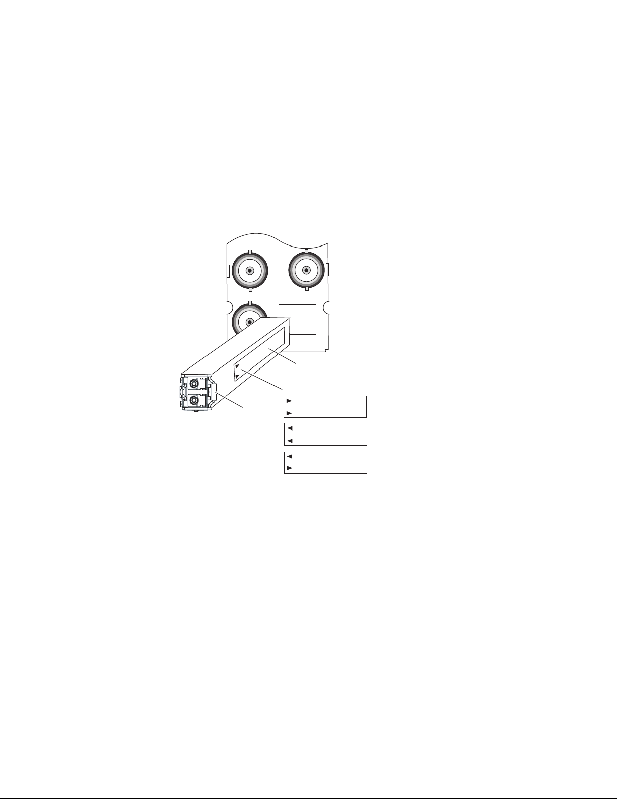
Installation
FIBER
J7J9J8
8431_03r3
Label
Handle
Arrow Indicators:
Fiber Optic Receiver
Fiber Optic Transmitter
Fiber Optic Transceiver
To install the fiber optic submodule:
1. Slide the fiber optic device into the metal fiber cage with the label and
handle to the right.
2. Push the device in as far as it will go without forcing it. It will not go
completely into the cage.
3. Cable the fiber optic connectors according to the instructions given in
Fiber Optic Video Inputs on page 22 or Fiber Optic Video Outputs on
page 22 depending on the type of submodule used.
Figure 6. Installing Fiber Optics Submodule
Removing an SFP Submodule
If you need to remove an SFP submodule, snap the handle out and pull the
submodule slowly out of the metal cage.
20 8995UPC/DNC/UDX — Instruction Manual
Page 21
Cabling
8480_01r3
8900UDX-R
Fiber Optic Cabling
FIBER
J1 J2
J3 J4
J5 J6
J7J9J8
Fiber Rx 1
Fiber Tx 2
Fiber Rx 2
J8: Video Out
Fiber Inputs/Outputs
(See Fiber Optic Cabling
at right)
J6: Video Out
J2: Auto Tracking
Delay Output
J4: Reclocked
Video Output
Fiber Optic Receiver
Fiber Optic Transmitter
Fiber Optic Transceiver
Fiber Tx 1
Fiber Rx 1
Fiber Tx 2
J1 and J3:
Genlock Ref
In Loop
J5: Video Out
J7: Video Out
J9: Video Input
Installation
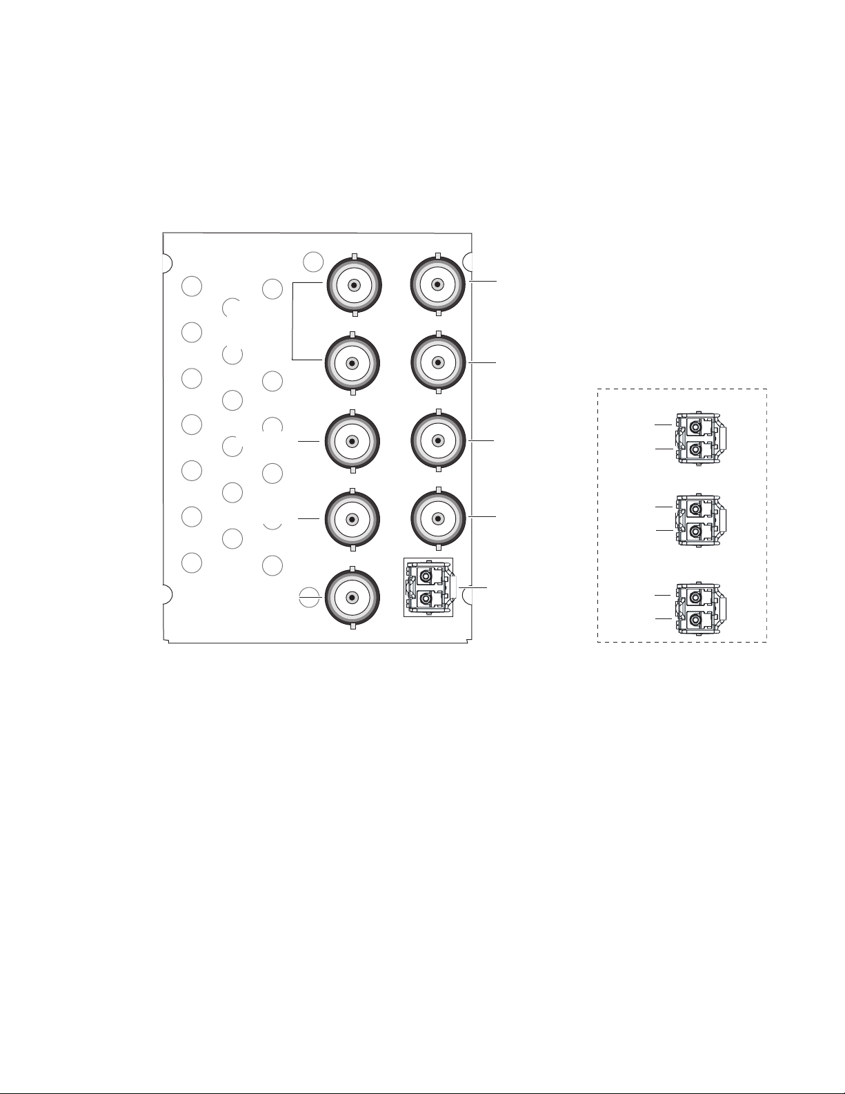
Cabling is done on the rear of the 8900UDX-R module illustrated in
Figure 7. Inputs and outputs are also illustrated on the I/0 Config web page
(I/O Config Web Page on page 46).
Figure 7. 8995UDX Rear Module
Genlock Loop
BNCs J1 and J3 are looping inputs to the optional Genlock submodule on
the 8995 module with an external genlock reference (NTSC/PAL color
black or Tri-level sync).
Connect an external reference to J1 or J3 and loop the other input to another
device or terminate the unused input.
Video Input
The input to the module can be connected to an electrical coax BNC and up
to two fiber optic connectors depending on the fiber optic submodule
installed. Only one video input can be active at a time and must be selected
on the Video Input web page (
page 54).
8995UPC/DNC/UDX — Instruction Manual 21
Page 22

Installation
Electrical Video Input
To use an electrical input, connect an HD or SD digital video signal to the
Coax input at BNC J9.
Fiber Optic Video Inputs
For fiber optic inputs, a dual receiver or transceiver SFP optical submodule
must be installed. Refer to the SFP Fiber Optic Submodule summary table
Ta bl e 1 on page 19) for the correct submodule to use. Connect the inputs
(
as illustrated in Figure 7 on page 21. Fiber connections must be cleaned
when cabling or after any de-mating cycle. Refer to Fiber Optic Cleaning
Requirement on page 19.
Video Outputs
There can be up to six video outputs from the module available at one time,
four electrical coax and up to two fiber optic outputs depending on the fiber
optic submodule used.
Electrical Outputs
There are four electrical coax video outputs at BNCs J5, J6, J7, and J8 always
enabled and available.
Fiber Optic Video Outputs
If an optical transceiver submodule is installed, one fiber optic output (TX2)
is available. If an optical dual transmitter submodule is installed, two fiber
optic outputs are available TX1 and TX2. Refer to the SFP Fiber Optic Sub
module summary table (Ta bl e 1 on page 19) for the correct submodule to
use. Fiber optic outputs must be enabled on the Fiber Out web page
(
page 78). Refer to Fiber Optic Cleaning Requirement on page 19 for cleaning
fiber optic connections before use.
Reclocked Video Output
One reclocked video output of non-processed input video is provided for
looping to other equipment. If a fiber input is being used, the reclocked
video from this input will also pass to this output.
Auto Tracking Output
-
BNC J2 output is an auto tracking delay signal that can be fed to audio
modules to synchronize the audio delay to match the delay of the 8995
module.
22 8995UPC/DNC/UDX — Instruction Manual
Page 23
Set Fan Speed to Maximum
Set the front cover fans to maximum speed to maximize the cooling in the
frame.
To increase fan cover speed:
1. Remove the front cover of the frame.
2. Remove the 8900NET module (next to the power supplies).
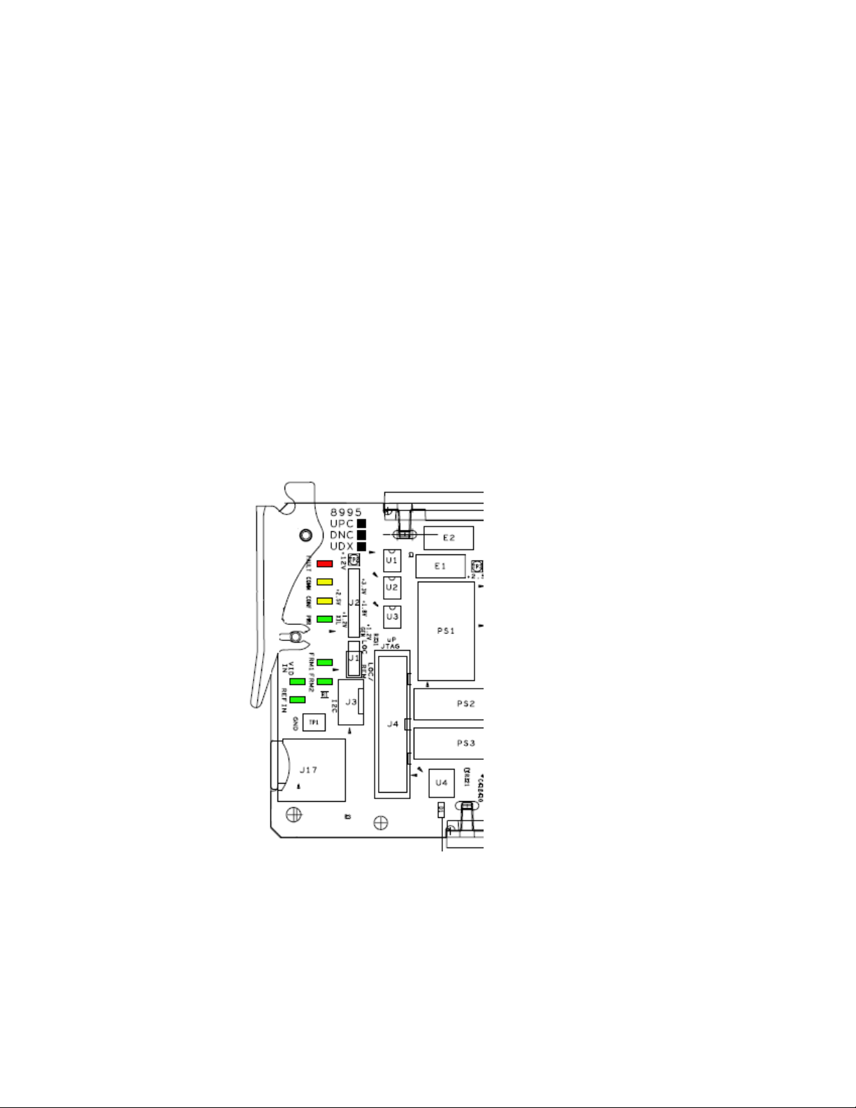
3. Locate Configuration DIP switch S1 (Figure 8).
4. Set position 7 to the right as shown in Figure 8.
5. Return the 8900NET module to the frame and replace the front cover.
Figure 8. Set 8900NET S1 for Maximum Front Cover Fan Speed
Set Fan Speed to Maximum
Configuration DIP switch S1
S2S1
S1
1
2
3
4
5
6
87
1
2
3
4
5
6
7
8
Fan Speed
at maxium
12345678
Remote
Override
LED
8900NET
12345678
075080000_02r0
8995UPC/DNC/UDX — Instruction Manual 23
Page 24
Power Up
Power Up
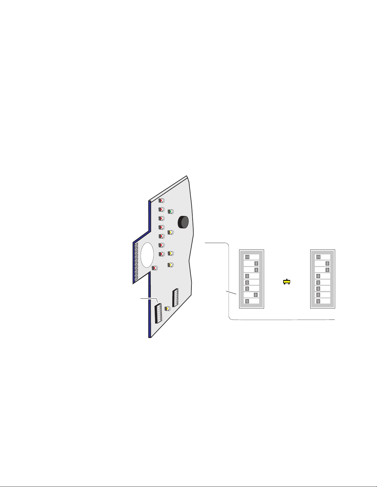
Operation Indicator LEDs
The front LED indicators and configuration switches are illustrated in
Figure 9. Upon power-up, the green PWR LED should light and the yellow
CONF LED should illuminate for a few seconds for the duration of module
initialization.
Note When a media module is first plugged into a GeckoFlex frame, the 8900NET
module (if present) may report a momentary fault. This will clear once the
media module has booted up.
With factory default configuration and a valid input signal connected, the
green PWR and (
illuminate (refer to Tab le 2 on page 25 to see the possible operating indicator combinations).
Figure 9) on the top side of the module front edge should
Figure 9. Front Panel LED Indicators
24 8995UPC/DNC/UDX — Instruction Manual
Page 25

Table 2. Board Edge LED Names and Meaning
LED Indication Condition
FAULT
(red)
COMM
(yellow)
CONF
(yellow)
PWR
(green)
FRM1
(green)
FRM2
(green)
VID IN
(green)
REF IN
(green)
Off Normal operation.
On continuously Module has detected an internal fault.
Flashing Configuration problems. Check inputs and settings. Missing video.
Off No activity on frame communication bus.
3 Quick Pulses Locate Module command received by the module from a remote control system.
Short flash Activity present on the frame communication bus.
Off Module is in normal operating mode.
On continuously Module is initializing, changing operating modes or programming hardware.
Off No power to module or module’s DC/DC converter failed.
On continuously Normal operation, module is powered.
Off Reference frame bus is disabled to frame on Genlock web page or no Genlock submodule is installed in slot 1.
On Reference frame bus is enabled on Genlock web page and Genlock submodule is installed in slot 1.
Off Reference frame bus is disabled to frame on Genlock web page or no Genlock submodule is installed in slot 3.
On Reference frame bus is enabled on Genlock web page and Genlock submodule is installed in slot 3.
Off Indicates no valid input signal is being detected.
On Indicates a valid input signal is being detected.
Off Indicates no valid reference signal is being detected or signal is not locked.
On Indicates a valid reference signal is present and locked.
Power Up
8995UPC/DNC/UDX — Instruction Manual 25
Page 26

Configuration
Configuration
Configuration Summary
The 8995 modules can only be configured remotely using the 8900NET
network interface GUI or a networked Newton Control Panel.
Refer to the following sections for configuration instructions:
• Configuration Overview (page 26)
• Remote Control and Monitoring (page 34)
• Configuration Parameter Summary (page 111)
Operation of these control types is explained in detail in their respective
sections of this manual.
This section provides a brief summary of all parameters that can be configured on the 8995 module. Use this section in conjunction with the specific
configuration method instructions for each configuration type.
page 111 provides a summary in table format of all parameters and their
ranges, default values, and remote, local, and control panel function names
and locations for setting each value.
Ta bl e 13 on
Video Input Selection
The video input source (Coax, RX 1, or RX 2) must be selected on the Video
Input web page. Fiber optic inputs available depend on the type of fiber
optic submodule installed. All inputs can have connections cabled, but
only one input can be used at a time.
Video Timing and Loss of Signal Controls
On a 8995 module with an external Frame Sync genlock timing source
selected, the following timing adjustments are available:
• Horizontal Timing – adjusts the horizontal delay of the channel output
in pixels
• Vertical Timing – adjusts vertical delay in line increments
Also available on the 8995 module are the following controls for setting the
output condition when there is a loss of input signal:
• Auto Blue – when Auto Blue is enabled on a channel, the output will
automatically freeze to a blue screen when the input signal is lost on the
input.
26 8995UPC/DNC/UDX — Instruction Manual
Page 27

• Auto Freeze – when Auto Freeze is enabled on a channel, the output
will automatically freeze on the last valid field when the input signal is
lost on the input.
• A Manual freeze can be performed at any time with the following two
choices:
•Frame
• Field
Note A field freeze provides less resolution and no motion artifacts in the output.
Signal Conversion
The 8995UDX module performs three main video conversion functions:
• Up Conversion – allows an SD signal input to be converted to an HD
output signal in the same time domain (480i/59.94 to 1080i/59.94 or
576i/50 to 1080i/50 for example).
Configuration
In frame mode, the resolution is higher since both fields are present, but the
presentation of the two fields can cause motion artifacts.
• Down Conversion – allows an HD signal input to be converted to an SD
output signal in the same time domain (1080i/59.94 to 480i/59.94 or
1080i/50 to 576i/50 for example).
• Cross Conversion – allows an HD signal input to be cross converted
between progressive signal types and interlaced signal types in the
same time domain (720p/59.94 to 1080i/59.94 or 1080i/50 to 720p/50
for example).
8995UPC/DNC/UDX — Instruction Manual 27
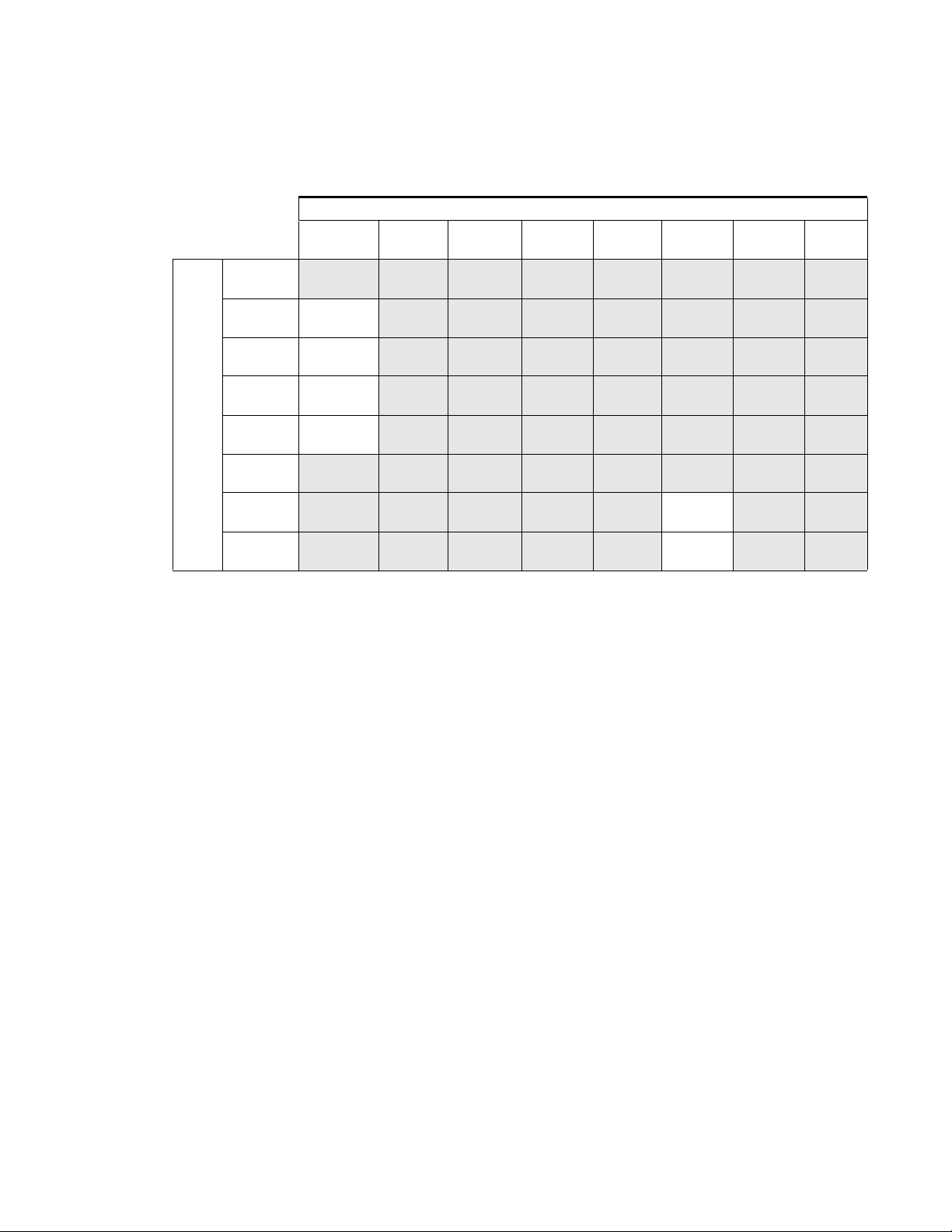
Page 28

Configuration
Input
Signal
480i
(SD/59.94)
720p
(59.94)
1080i
(59.94)
1080p
(23.98
1080sf
(23.98
576i
(SD/50)
720p
(50)
1080i
(50)
The various up, down, and cross conversion possibilities for all input signal
to output signal selections are shown in
Note Note that all conversions must occur in the same time domain or they will be
invalid. Invalid conditions are grayed out.
Table 3. 8995UDX Up, Down, and Cross Conversion
Output Signal
480i
(SD/59.94)
Down
Convert
Down
Convert
Down
Convert
Down
Convert
720p
(59.94)
Up
Convert
Cross
Convert
Cross
Convert
Cross
Convert
1080i
(59.94)
Up
Convert
Cross
Convert
Cross
Convert
Cross
Convert
1080p
(23.98
Up
Convert
Cross
Convert
Cross
Convert
Cross
Convert
Ta bl e 3 for the 8995UDX.
1080sf
(23.98
Up
Convert
Cross
Convert
Cross
Convert
Cross
Convert
576i
(SD/50)
Down
Convert
Down
Convert
720p
(50)
Up
Convert
Cross
Convert
1080i
(50)
Up
Convert
Cross
Convert
Input
Signal
480i
(SD/59.94)
720p
(59.94)
1080i
(59.94)
1080p
(23.98)
1080sf
(23.98)
576i
(SD/50)
720p
(50)
1080i
(50)
Ta bl e 4 shows the possible input and output conditions for the 8995UPC
Up Converter module or up conversion on the 8995UDX.
Table 4. 8995UPC/8995UDX Up Conversion
Output Signal
480i
(SD/59.94)
720p
(59.94)
Up
Convert
1080i
(59.94)
Up
Convert
1080p
(23.98)
Up
Convert
1080sf
(23.98)
Up
Convert
576i
(SD/50)
720p
(50)
Up
Convert
1080i
(50)
Up
Convert
28 8995UPC/DNC/UDX — Instruction Manual
Page 29
Input
Signal
480i
(SD/59.94)
720p
(59.94)
1080i
(59.94)
1080p
(23.98)
1080sf
(23.98)
576i
(SD/50)
720p
(50)
1080i
(50)
Configuration
Ta bl e 5 shows the possible input and output conditions for the 8995DNC
Down Converter module or down conversion on the 8995UDX.
Table 5. 8995DNC/8995UDX Down Conversion
Output Signal
480i
(SD/59.94)
Down
Convert
Down
Convert
Down
Convert
Down
Convert
720p
(59.94)
1080i
(59.94)
1080p
(23.98)
1080sf
(23.98)
576i
(SD/50)
Down
Convert
Down
Convert
720p
(50)
1080i
(50)
Color Correction
Color correction controls are provided for making RGB gain, offset and
gamma correction adjustments. Each color channel can be adjusted sepa
rately or a total gain or total gamma can be applied to all channels.
Gamma controls brighten and darken the gray intensity of the signal.
Raising the gamma above 1.0, brightens the gray intensity. Lowering the
gamma below 1.0, darkens the gray intensity.
Video Processing Adjustments
Component level (Y, Cr, Cb) adjustments are provided in the Video processor for video gain and offset, chroma gain, phase control (hue), and color
saturation. Each color component can be adjusted separately or the total
gain can be adjusted.
Y/C clipping controls are available in the Video Proc for adjusting the top
(white) and bottom (black) luminance levels and the white clipping on
chrominance channel of the output signal (C White Clip)
Image enhancement controls include a noise reduction control, edge
expansion, extended color space, vertical edge filtering, and a matte edge
border.
-
8995UPC/DNC/UDX — Instruction Manual 29
Page 30

Configuration
Cadence controls are present for selecting between two modes to handle
automatic cadence detection in video created from film. The first (and
default) choice is
that has a 1/23.98 Hz capture interval must use a process called 3:2 pull
down to produce video fields at 1/59.94 Hz intervals.
If artifacts occur in Auto Film/Video (3:2 or 2:2 pull down mode, automatic
cadence detection may be disabled by selecting the second choice,
Video (2:2 pull down)
motion-adaptive de-interlacing assuming only a 2:2 cadence in the video,
reducing the chance of distortion related to cadence detection.
Aspect Ratio Controls
Aspect ratio controls are provided on this module for changing various
characteristics of the output image after an up or down conversion using
the mode, alignment, position, and crop controls (when applicable).
The module also detects and reports whether Active Format Description
(AFD) information is present on the input/output signal. The AFD Input
and Output Status sections report the presence of AFD, the AFD Input and
Output Line, the Input and Output Aspect Ratio (4:3 or 16:9), and the AFD
Input and Output AFD code.
Auto Film/Video (3:2 or 2:2 pull down). Video created from film
Fixed
mode. In this mode, the de-interlacer to performs
The AFD Input and Output codes are defined as 4-bit binary numbers.
Each 4-bit code describes a video picture in terms of aspect ratio and other
characteristics of the active image based on the SMPTE 2016-1:2009 and
2016-3:2009 standards.
When present, AFD processing can be disabled in the AFD Control section
if desired. When disabled, AFD reporting information will remain on the
web page but will be bypassed when the aspect ratio controls are used. The
aspect ratio controls will act on the video output in the same manner as
when no AFD is detected or AFD is disabled as described in
(No AFD or AFD Disabled) on page 31.
The following sections describe using the aspect ratio controls on signals
with and without AFD:
Aspect Ratio
Aspect Ratio (AFD Present)
When AFD is present on the input and AFD is enabled, the aspect ratio controls will change the output as defined by specific software programming
designed to meet the requirements of the SMPTE 2016-1:2009 and
2016-3:2009 AFD code standards.
AFD input and output codes are defined in the Appendix section: Active
Format Description on page 117. This Appendix provides detailed defini-
tions of the binary codes and how the AFD codes respond to the aspect
ratio settings made on the web page when AFD is present.
30 8995UPC/DNC/UDX — Instruction Manual
Page 31

Configuration
Complete picture appears in Full Height
format with horizontal cropping.
Also known as Center Cut mode.
Position picture with horizontal
alignment and cropping controls.
Full Height (Center Cut)
8480_06r2
Shift horizontally
Aspect Ratio (No AFD or AFD Disabled)
When the input signal has no AFD coded information on it (reported on the
Aspect Ratio web page as
abled in the AFD Control section, the aspect ratio mode selections are available as described in the section below.
Note The default Aspect Ratio web page will also include an Auto mode if the input
signal has no AFD. Auto mode is used only when AFD is present. Disabling
AFD when present will remove the Auto mode button on the web page.
• Full Width – this mode will stretch a down converted image to fit the
screen with top and bottom margins. An image set to this mode will
appear centered horizontally in a 16:9 display with black bars on the top
and bottom of the screen (letterbox) as illustrated in Figure 10. The
image can be aligned with the aspect ratio controls and the matte color
of the background can be changed.
Figure 10. Full Width Aspect Ratio
Not Present) or if the AFD processing has been dis-
Full Width
Complete picture appears in Full Width
format with top and bottom margins.
Position picture vertically with alignment
controls and crop vertical lines.
Set matte color of top and bottom
margins.
Shift
vertically
8480_07r1
• Full Height – this mode, also known as Center Cut, presents the entire
picture with horizontal cropping. An image set to this mode will appear
centered vertically in a 16:9 display with some cropping on either side
as shown in Figure 11. The image can be adjusted with the horizontal
aspect ratio controls.
Figure 11. Full Height Aspect Ratio
8995UPC/DNC/UDX — Instruction Manual 31
Page 32

Configuration
Shift
vertically
Shift horizontally
Minimized left and right cropping
of picture with top and bottom
margins. Position picture vertically
and horizontally with alignment
controls and crop vertical lines.
Set matte color of top and bottom
margins.
14x9 SP: Down Conversion
= lost picture
Shift horizontally
Top and bottom cropping;
Position left, center, or right
= lost picture
14x9 SP: Up Conversion
• Anamorphic – this mode is designed to be used with material originally
captured with an anamorphic lens. It ensures that the top and bottom
edges of the input aspect ratio match the top and bottom edges of the
output aspect ratio. When used with standard 4:3 material, it will have
the effect of stretching the material horizontally as illustrated in
Figure 12. This results in a distortion of the geometry of the image, par-
ticularly causing circles to appear as ovals when present in the image if
the input image was not recorded with an anamorphic lens.
Figure 12. 16:9 Anamorphic Mode
Anamorphic Aspect Ratio
Displays all pixels, no loss of picture,
Displays all pixels, no loss of picture,
but stretches image height. Circles will
but stretches image height. Circles will
appear as ovals. No positioning
appear as ovals. No positioning
controls are used.
controls are used.
8480_09r1
• 14 x 9 SP – this mode minimizes the left and right cropping of the image
and stretches it leaving the result for both down and up conversion as
shown in Figure 13. The image can be aligned with the aspect ratio controls and the matte color of the background can be changed.
Figure 13. 14 x 9 SP Aspect Ratio
32 8995UPC/DNC/UDX — Instruction Manual
Page 33

Transcoding
The module is capable of transcoding same-rate (59.94 Hz) closed caption
and VITC data. Refer to the detailed explanation in
page 66.
Note VITC and CC transcoding is not supported in 1080p/sf 23.98.
Audio Processing and Configuration
Audio status for up to eight audio streams in four embedded audio groups
present in the input video is monitored and reported. Controls are pro
vided for adjusting gain on individual audio channels in each of the
streams (2 streams per group, each stream having a Channel A and
Channel B) and re-pairing audio channels into the four output groups as
desired (or forcing to Silence) and reinserting the processed audio into the
video output. Refer to the
Functional View Web Page on page 53.
Genlock Controls
Configuration
Transcoding Web Page on
-
On modules with an 8900GEN-SM Genlock submodule installed
(8995UDX+GEN, 8995DNC+GEN, or 8995UPC+GEN) the Genlock web
page and control panel controls will be available. Use these controls to
enable the external genlock reference and set control and timing parame
ters for the module. Refer to Genlock Submodule Installation on page 16 for
installation instructions.
User Settings
Module default parameters and default signal names can be recalled at any
time for the entire module or subsets of parameters such as the color cor
rector or video processor.
On the web pages, a Defaults button at the bottom of each applicable web
page is available to return the parameters on that page to the factory
defaults.
Save and load module configuration to/from a file are also provided on
this web page.
Fiber Optic Outputs
When there is a Dual Transmitter (TX1 and TX2) or a Transceiver (TX2) fiber
optic submodule installed, one or both fiber outputs can be enabled for
operation. Refer to
your software version. Be sure to follow the instructions for preparing the
fiber cables given in
-
-
Ta bl e 1 on page 19 for the correct submodules to use for
Fiber Optic Cleaning Requirement on page 19.
8995UPC/DNC/UDX — Instruction Manual 33
Page 34

Configuration
Local/Remote
Jumper, J1
Remote Configuration and Monitoring
8995 module configuration and monitoring can only be performed using a
web browser GUI interface or a networked Newton Control Panel when
the 8900NET Network Interface module is present in the GeckoFlex frame.
Each of these interfaces is described below.
Local/Remote Jumper
The on-board jumper Local/Remote jumper, J1, (Figure 14) must be set for
local and remote (LOC/REM position, pins 2-3) for remote control or set to
(LOC position, pins 1-2) to lock out remote control.
Figure 14. Module Configuration Switches and LEDs
8900NET Module Information
Refer to the 8900NET Network Interface Module Instruction Manual for information on the 8900NET Network Interface module and setting up and
operating the GeckoFlex frame network.
Note The 8900NET module in the GeckoFlex frame should be running software
version 4.3.0 or higher for optimum remote and control panel operation and
is required for software updating. Upgrade software and instructions for the
8900NET can be downloaded from the Grass Valley web site. See System
Requirements on page 11 for 8900NET software updating.
34 8995UPC/DNC/UDX — Instruction Manual
Page 35

Newton Control Panel Configuration
A Newton Control Panel (hard or soft version) can be interfaced to the
GeckoFlex frame over the local network. Refer to the documentation that
accompanies the Newton Modular Control System for installation, config
uration, and operation information.
Control panel access offers the following considerations for module configuration and monitoring:
• Ability to separate system level tasks from operation ones, minimizing
the potential for on-air mistakes.
• Ability to group modular products—regardless of their physical loca-
tions—into logical groups (channels) that you can easily manipulate
with user-configured knobs.
• Update software for applicable modules and assign frame and panel IP
addresses with the NetConfig Networking application.
• Recommended for real-time control of module configuration parame-
ters, providing the fastest response time.
Configuration
-
Note Not all module functions are available with the control panel, such as E-MEM
and factory default recalls. The available control panel controls for the 8995
modules are listed in Table 13 on page 111.
An example of the Newton Configurator is shown in Figure 15.
Figure 15. Newton Configurator Example
8995UPC/DNC/UDX — Instruction Manual 35
Page 36

Configuration
Web Browser Interface
The web browser interface provides a graphical representation of module
configuration and monitoring.
Use of the web interface offers the following considerations:
• Provides complete access to all module status and configuration functions, including naming of inputs and outputs, factory parameter and
name default recalls, E-MEM functions, slot configuration, and SNMP
monitoring controls.
• Web access will require some normal network time delays for processing of information.
• Configuration parameter changes may require pressing
Enter, upload processing time, and a manual screen refresh to become
effective.
• Web interface recommended for setting up module signal and slot
names, E-MEMS, and reporting status for SNMP and monitoring.
Refer to the Frame Status page shown in Figure 16 on page 37. The modules
can be addressed by clicking either on a specific module icon in the frame
status display or on a module name or slot number in the link list on the
left.
Note The physical appearance of the menu displays on the web pages shown in
this manual represent the use of a particular platform, browser and version
of 8900NET module software. They are provided for reference only. Displays
will differ depending on the type of platform and browser you are using and
the version of the 8900NET software installed in your system. This manual
reflects an 8900NET module with software version 4.3.0, using Internet
Explorer, the recommended web browser, and Windows XP operating
system.
For information on status and fault monitoring and reporting shown on the
Status page, refer to
Status Monitoring on page 106.
Apply button or
36 8995UPC/DNC/UDX — Instruction Manual
Page 37

Figure 16. GeckoFlex Frame Status Page
The Links section lists the frame and its current modules. The selected link's Status
page is first displayed and the sub-list of links for the selection is opened. The sub-list
allows you to select a particular information page for the selected device.
Configuration
Content display section
for the selected frame or module (frame slot icons are also
active links).
Refresh button for manual
update of page
displays the information page
8480_02r0
8995UPC/DNC/UDX — Instruction Manual 37
Page 38

Configuration
Pulldown Menus
Button
Radio button
Check box
Refresh button
Coarse Adjust
Fine Adjust
Enter
Low Limit
Status Indicator
Entry Field
High Limit
Web Page Operations and Functional Elements
The following conventions and functional elements (shown at left) are used
in GeckoFlex web page operations. (The examples shown throughout this
manual represent 8900NET software version 4.3.0 or later):
• Pulldown menus allow you to choose selections from a list.
• Clicking on a button performs an immediate action such as recall of
defaults, clearing of states, learning configurations, and selecting all or
none of a selection.
• Radio buttons are used to make a choice of one parameter in a group.
• Check boxes are used when a selection can be enabled or included in a
group. Multiple check box selections or enables can be made for some
parameters.
Refresh button (circular arrow) is provided at the top of each web page
•A
for manual refresh to view and update recently changed parameters.
• Each numerical adjustment control has a
right top double arrows) which increases or decreases the step value by
a factor of 10. The
Fine adjust button (left and right inside single arrows)
increases or decreases the step value by 1.
To change a value, use the arrow button controls or enter a value into
the number field and select the
Enter button (*) or use the Enter key on
your keyboard. The Status Indicator bar will follow the value selected.
Coarse adjust button (left and
Status LED
Use the Low and High Limit buttons to go directly to the lowest and
highest limits for the parameter.
8341_13r1
• An entry field allows naming of various module functions such as
input or output signals, asset tag, and slot identification.
•The
Status LED icon reports communication status for the frame slot and
is a link to the module Status web page where Warnings and Faults are
displayed.
LED colors indicate:
• Green = Pass – no problems detected
• Yellow = Configuration error warning
• Red = Fault condition detected
38 8995UPC/DNC/UDX — Instruction Manual
Page 39

Configuration
Web Page Headers
Each configuration web page has a Status and Identification Header as
shown in
Figure 19 for the 8995UDX.
Figure 17. 8985UPC Status /ID Header
Figure 18. 8985DNC Status /ID Header
Figure 17 for the 8995UPC, Figure 18 for the 8995DNC, and
Figure 19. 8995UDX Status/ID Header
When any of the 8995 modules have an 8900GEN submodule installed, the
header shows the addition of the Genlock with + GEN (
Figure 20. 8995UDX + GEN Status Web Page
Figure 20).
8995UPC/DNC/UDX — Instruction Manual 39
Page 40

Configuration
The header information on each web page includes the following:
• Model and Description are read-only generated by the module.
Frame Location is defined on the 8900 Series GeckoFlex Frame Configura-
•
tion web page.
Slot number reports the module’s location in the frame.
•
Input Video Standard reports the input video type and rate selected on the
•
System Config web page.
•
Input Video reports the status of the video input to the module.
Output Timing Source reports the output timing source (Local, Ref 1, Ref 2
•
or Input) chosen on the System Config web page.
Output Video Standard reports the current output video format selected.
•
Fiber Module Type reports the type of SFP fiber module installed or Not
•
Installed.
Web pages with configuration parameters each have a Defaults button at the
bottom of the page to allow resetting of
page.
default parameters for only that
Web Page Links
The web interface GUI provides the following links and web pages for the
8995 modules (Figure 21 on page 42):
• Status – reports input video and refer
Fiber Optic and Genlock option submodules, and module hardware
and software version information (page 43),
• I/O Config – shows a graphic representation of inputs and outputs to
the module and allows naming of each input and enabling and disabling of signal reporting (page 46),
• System Config – set the I/O standard for the input and output of the
module, the output timing source, colorbars test output, and Reference
Restore parameters (page 48),
• Functional View – provides a graphical block diagram of the video and
embedded audio configuration pages for the module with links to each
web page (page 53),
• Video Input – allows selection of the video input source (Coax or fiber)
and provides the status of all sources, including fiber optic submodule
option inputs (page 54),
• Frame Sync – provides horizontal and vertical timing and loss of signal
controls for the 8995 module, multi-frame delay selection, minimum
delay mode, manual freeze mode, and timing status tables (page 55),
ence signal status, presence of
• Color Correction – provides RGB gain, offset and gamma correction
adjustments (page 62),
40 8995UPC/DNC/UDX — Instruction Manual
Page 41

Configuration
• Video Proc – provides overall video processing for the HD or SD signal
along with Y/C White and Y/Black clip controls, and image enhancement controls for noise reduction, and enabling of edge expansion,
extended color space, vertical edge filter, matte edge border, and
Cadence controls (page 63),
• Transcoding – enable the Closed Captioning and VITC transcoding
functions and set parameters for line positioning in the vertical interval
(page 66),
• Aspect Ratio – set the desired aspect ratio, cropping, and matte color for
the output video, reports AFD (Active Format Description) input and
output status and disabling/enabling AFD (page 73),
• Video Out – enable or disable the fiber optic outputs when a dual trans-
mitter or transceiver fiber optic submodule is installed and enable
audio re-embedding (page 78),
• Audio Input Status – reports the input status of embedded audio on the
video input signal (page 79),
• Audio Delay – allows setting delay on Channel A and B of each audio
stream (page 80),
• Audio Gain – allows setting gain on Channel A and B of each audio
stream (page 82),
• Audio Channel Pairing – allows recombining of audio channels within
the four audio output groups (page 84),
• Audio Proc – allows selection of the type of audio processing for Stream
1 and 2, Channel A and B, of the four final audio groups 1-4 (page 86),
• Genlock – appears only on module links when the optional
8900GEN-SM submodule is installed on the module. This web page
provides status reporting for the external genlock reference and controls for enabling the Genlock, matching the reference input to a selection standard, and setting reference signal delay (page 88),
• User Settings – allows recalling of factory defaults for all module
parameters or factory signal names, and provides a save/load configuration file function (page 92), and
• Slot Config – provides Locate Module and Slot Memory functions
along with links to the SNMP, LED Reporting, and Frame Alarm configuration web pages (page 95).
8995UPC/DNC/UDX — Instruction Manual 41
Page 42

Configuration
Figure 21. 8995UDX/UPC/DNC Web Page Links
42 8995UPC/DNC/UDX — Instruction Manual
Page 43

Status Web Page
Use
this
link
The Status web page (Figure 22 on page 44 shows an example of the
8995UDX + GEN) reports the input signal status of
the reference inputs and outputs in both graphical and textual formats. It
also provides status reporting for the optional Genlock and Fiber Optic
submodules. Color coding of the display and the Status LED indicates the
signal status. Refer to Status Monitoring on page 106 for a complete explanation of the color coding.
Module Physical Structure
Status is reported for each of the following video or reference signals:
• Video In – indicates the status of the video input to the module from the
coax BNC,
type of fiber optic connector installed).
• Video Out – not monitored in this application.
• Genlock Ref In – indicates the status of the external genlock reference
signal at BNCs J1 and J3 (Genlock Loop).
Configuration
each of the video and
or one of two possible fiber optic inputs (depending on the
• Local Ref – indicates the status of the internally generated genlock ref-
erence signal from the 8900GEN submodule to the front module.
• Frame Bus – indicates the status of the communication bus to the
8900NET module.
• Ref 1 and Ref 2 In (From Frame) – the Ref 1 arrow will be present when
Frame Bus 1 has been enabled on the module in slot 1. The Ref 2 arrow
will be present when Frame Bus 2 has been enabled on the module in
slot 3 of the frame.
When the module detects an error, a warning messages, such
reference not present, will appear between the lines below the status
graphic as illustrated in Figure 22 on page 44. Refer to the I/O Config Web
Page on page 46 for information on disabling the status reporting.
Note Many of these warnings are informational only and concern frame rate com-
patiblilty. Pay close attention to the frame rate compatibility explanations and
tables in this manual.
The installation status of the Genlock Module or Fiber Optic submodule
will also be reported here as well as being shown in the graphic.
Information about the module, such as part
ware revision and software and firmwar
(assigned on the Slot config web page) are given in a read-only section at
the bottom of the display.
number, serial number, hard-
e versions, and asset tag number
as signal or
8995UPC/DNC/UDX — Instruction Manual 43
Page 44

Configuration
Figure 22. 8985UDX Status Web Page
44 8995UPC/DNC/UDX — Instruction Manual
Page 45

Configuration
Warnings and configuration errors are also reported on the Status web page
between the double lines as shown in
Figure 23. Warnings and Configuration Error Reporting
Figure 23.
8995UPC/DNC/UDX — Instruction Manual 45
Page 46

Configuration
Use
this
link
I/O Config Web Page
Use the I/O Config web page (Figure 24 on page 47) for the following:
Rear Connectors
All of the input and output connectors on the corresponding 8995UDX-R
rear module are illustrated on the I/O Config web page. The inputs can be
configured with the following controls:
Signal Naming – use the factory default signal names or type the desired
•
input name (up to 11 characters) into the corresponding boxes for each
input. The status of each input is indicated by the color of the display.
Reporting Enabling – status reporting of each input type can be enabled or
•
disabled by selecting or deselecting the corresponding checkbox in the
Reporting Enabled column for each input type. You may disable reporting
for inputs not being used if desired to avoid error messages. Status
color of the signal will not change. The
with an SNMP monitoring application such as NetCentral.
Reporting Enabled column used
Refer to Status Monitoring on
coding and using an SNMP monitoring application.
Note Outputs are not monitored in this application.
page 106 for an explanation of the color
46 8995UPC/DNC/UDX — Instruction Manual
Page 47

Figure 24. I/O Config Web Page with Factory Default Signal Names
Configuration
8995UPC/DNC/UDX — Instruction Manual 47
Page 48

Configuration
Use
this
link
System Config Web Page
Use the System Config web page (Figure 26 on page 49) to set the system
configuration parameters for the module. For a complete list of module
paramet
8995UDX/UPC/DNC Configuration Functions on page 111.
Test Output
Enable the colorbars test signal on the module output with the Enabled
button.
Video I/O Configuration
The following controls are available in this section:
•
ers, refer to the summary table in the Summary of
Ref Input – displays the reference input standard connected to the
Genlock Loop through BNCs on the rear module. Refer to Table 6 on
page 51 for a listing of output standards and compatible frame refer-
ences.
Input Standard – choose the desired input standard from the pulldown
•
choices or use the
reported in the web page header as the Input Video Standard. When
Auto is selected, the input signal type detected on BNC J9 will be
reported.
Output Standard – choose the desired input standard from the pulldown
•
choices. This will determine what action the module will perform, up
conversion, down conversion, or cross conversion.
Refer to Signal Conversion o
types and valid and invalid conditions.
When a new configuration has been selected with the Input and Output
Standar
Figure 25, a message will appear indicating
tings button to commit changes
Figure 25. Changes Pending Message
d pulldowns, such as a up conversion operation shown in
Auto selection. The signal input type selected will be
n page 27 for an explanation of the conversion
Changes Pending: Click Apply Set-
.
48 8995UPC/DNC/UDX — Instruction Manual
Page 49

Figure 26. System Config Web Page
Configuration
8995UPC/DNC/UDX — Instruction Manual 49
Page 50

Configuration
Select the Apply Settings button to perform the action. Some conversions (typically up and down conversion) require a reconfiguring of parameters on
the module and a
appear while the operation is performed.
Note Once the web page reappears, it may be necessary to use the Refresh button
to update the page to show the correct values now configured.
Figure 27. Please Stand By Message
When the module detects an invalid condition relating to input/output
conversion (such as down converting between different line rates 59.94 and
50 for example), a warning message will appear similar to the one shown
in
Figure 28. The warning message will indicate why this operation is not
supported.
Please standby ... reconfiguring message (Figure 27) will
Figure 28. Invalid Signal Conversion Warning Message
Configuration errors on the System Config web page will also be reported
on the Status web page as shown in
Figure 23 on page 45.
50 8995UPC/DNC/UDX — Instruction Manual
Page 51

Configuration
Ta bl e 6 give the various output video standards and the frame references
that are compatible with each type.
Table 6. Output Video and Frame Reference Compatibility
Video Output Standard
480i
576i
1080i 59.94
720p 59.94
1080i 50
720p 50
1080p 23.98
1080sf 23.98
1
No multi-frame indexing is present on these reference signals to handle the 5:4 ratio between the
59.94 and 23.98 Hz frame rates.
2
Only an NTSC reference with SMPTE 318-M-1999 10-field marker will ensure frame synchroni-
zation of the 1080p/23/98 video.
Reference
Detected
NTSC None
1080i 59.94 TLS None
720p 59.94 Yes
PAL None
1080i 50 TLS None
720p 50 TLS Yes
1080i 59.94 TLS None
NTSC None
720p 59.94 TLS Yes
720p 59.94 TLS None
NTSC None
1080i 59.94 TLS None
1080i 50 TLS None
PAL None
720p 50 TLS Yes
720p 50 TLS None
PAL None
1080i 50 TLS None
720P 59.94 TLS Yes
1080i 59.94 TLS Yes
NTSC Yes or No2
1080p 23.98 TLS Yes
720P 59.94 TLS Yes
1080i 59.94 TLS Yes
NTSC Yes or No
1080sf 23.98 TLS Yes
Mismatch
Warning
1
1
1
1
1
1
1
1
1
2
1
Note The 3:2 pulldown cadence of 29.97Hz output video may be synchronized to
a SMPTE 318M-B reference (NTSC with 10-field marker) as long as every 4th
frame of the 23.98Hz input video is synchronous to the start of the 10-field
sequence in this reference.
The 2:3 inverse pulldown cadence of 23.98Hz output video may be synchronized by the 8995UDX module to a SMPTE 318M-B reference.
8995UPC/DNC/UDX — Instruction Manual 51
Page 52

Configuration
Output Timing
Select the Primary and Secondary output timing source for the module as
either
Local (external reference from the 8900GEN-SM submodule mounted
on this module),
in slot 1 and jumpered for outputting a Ref 1 frame bus),
(8900GEN-SM submodule is mounted on module in slot 3 and jumpered
for outputting a Ref 2 frame bus), or
input video. The signal and genlock status of each reference source will be
reported in the Status and Genlock columns.
When a Secondary reference source is selected and different than the Primary, the module can be configured to switch automatically to the Secondary selected if the Primary is lost or becomes unlocked or invalid. If you
do not want this action of switching to a secondary, set the Primary and Sec
ondary sources to the same source.
Note An 8995 module can switch between the REF1 and REF2 sources from dif-
ferent genlock submodules that are locked to the same reference signal, and
maintain stable output video genlock.
Ref Bus 1 (8900GEN-SM submodule is mounted on module
Ref Bus 2
Input, the reference is taken from the
-
Reference Restore
If the Primary source has failed and a Secondary source is selected and
valid, the following controls allow you to set the module to switch back to
the Primary automatically or manually and determine the amount of time
before the Primary is restored.
• Switch to Primary – set this control to Manual if you wish to manually
return to the Primary reference when it becomes valid or locked again
or
Auto to allow the module to switch back to the Primary reference.
Reference Switchback Delay – when the control above is set for Auto, set the
•
amount of time to allow between switching from the Secondary reference back to the restored Primary. The switchback time has a minimum
recovery time of 30 seconds to assure that the Primary is locked and
valid before the module switches back to this source.
Primary – Secondary Phase Difference
This graphic is provided to show the total phase difference between the
Primary and Secondary references. When the bar is green and remains in
the area before the horizontal indicator, the two references are in a range
where switching between the two will show no measurable disturbance in
the output video (approximately 72
ns).
When the phase difference is larger than the recommended amount, the bar
will indicate a second red bar. This indicates that the phase difference is
now such that switching between the two references will show a distur
bance in the output video. This can be caused by a loss of one of the references or a mis-adjustment in the reference output delay of either reference.
The total phase error shown in this graphic represents approximately 1 us.
52 8995UPC/DNC/UDX — Instruction Manual
-
Page 53

Functional View Web Page
Use
this
link
The Functional View web (Figure 29) page illustrates a block diagram of the
8995 front media modules showing module functions
paths in the current configuration. It can be used as a link map for configuring module functions. Each block has a link to the
that function.
Configuration
and active signal
configuration page for
• Color coding indicates active funct
nents are inactive due to hardware and/or software constraints.
• Use the Functional View to configure the 8995 configuration web pages
in the order of the signal flow. Underlined module functions in each box
are links to the web page for that function.
Figure 29. Functional View Web Page
ions and signal flow. Grayed compo-
• Each configuration web page shown in the Functional View will have
links to the
Next >> web page similar to Figure 30.
Figure 30. Configuration Web Page Links
8995UPC/DNC/UDX — Instruction Manual 53
<< Previous web page, the Functional View web page, and the
Page 54

Configuration
Use
this
link
Video Input Web Page
Use the Video Input web page (Figure 31) to select and monitor the video
input source to the module with the following:
Video Input Selection
This section provides the following for the video input signal:
Select Input Video – select the input source from the rear module as either
•
Coax, Fiber RX 1, or Fiber RX 2.
Note Fiber optic inputs require the presence of a fiber optic submodule. See Fiber
Optic Video Inputs on page 22.
• Signal Name – the signal name defined on the I/O Config web page by
the user or the default names will appear in each field.
•
Signal State – this field reports the status of the input video signal as
Present, Not Present, or Not Supported (no fiber submodule installed).
Figure 31. Video In Web Page
54 8995UPC/DNC/UDX — Instruction Manual
Page 55

Frame Sync Web Page
Use
this
link
The Frame Sync web page provides timing adjustments for horizontal and
vertical timing, multi-frame delay selection,
mode, loss of signal choices, manual freeze mode choices, and a timing
status table for the 8995 module.
Note The controls available on the Frame Sync page depend on the Output Timing
Source selected on the System Config web page.
Timing Adjustment
When no Frame Sync option is present or selected as the reference source,
the module is in line sync mode. The module reference source can be set to
Input on the System Config web page. Controls available in this mode will
appear as shown in Figure 32 on page 56.
Configuration
enabling of minimum delay
When the Frame Sync option is present and the
Local, Ref 1, or Ref 2 output
timing sources are selected, horizontal and vertical timing adjustments can
be made on the output video as required relative to the external reference
with the controls described below. Refer to Tab le 7 on page 60 for the list of
frame sync pixel and line timing adjustment ranges for input to output
deo combinations.
vi
H Timing (Pixels) – the horizontal timing can be adjusted in pixels relative
•
to the external reference.
V Timing (Lines) – the vertical timing can be adjusted in lines relative to
•
the external reference.
Multi-Frame Delay – this control allows you to add up to 6 frames of delay.
•
When the H and V Timing controls are set to maximum, the total delay
of the module will be 8 frames (when
Minimum Delay Mode is not
selected).
Minimum Delay Mode
A Minimum Delay Mode can be enabled to bypass portions of the frame
sync memory to allow an absolute minimum amount of delay through the
module. It is a special mode allowing the user to select a throughput delay
of about one frame when the input is synchronous and its position with
respect to the reference is well known. To enable this mode, check the
Enabled checkbox. Refer to Figure 34 on page 58 for an example of this set-
ting.
Note Delay can be added when in Minimum Delay Mode without causing video dis-
tortion up to one line short of a whole frame period of user delay. For normal
delay operations, Minimum Delay mode should be disabled.
Refer to Tab le 9 on page 99 for the delay values for each format.
8995UPC/DNC/UDX — Instruction Manual 55
Page 56

Configuration
Figure 32. Frame Sync Web Page – Input Reference Source
56 8995UPC/DNC/UDX — Instruction Manual
Page 57

Figure 33. Frame Sync Web Page – External Reference Source
Configuration
8995UPC/DNC/UDX — Instruction Manual 57
Page 58

Configuration
Figure 34 illustrates the Frame Sync timing status when Minimum Delay
Mode is enabled.
Figure 34. Frame Sync with External Reference – Minimum Delay Enabled
58 8995UPC/DNC/UDX — Instruction Manual
Page 59

Configuration
Loss of Signal Operation
Set the operation to be performed by the module upon loss of input signal
when an external reference is present (
When there is no external reference (output timing set to Input), the
module will default to pass the signal to the output.
Auto Blue, Auto Freeze, or Pass).
Manual Freeze Mode
Select one of the radio buttons (Frame or Field) to perform a manual freeze
on the output
.
Delay Wrap Position
This indicator will display with a blue bar, the fraction of the final frame of
actual video delay through the frame sync.
Note It will not indicate if multiple frames have been selected with the Multi-Frame
Delay control.
For example, with 1080i video and Minimum Delay Mode not selected, if
600 lines plus 5 frames of delay is entered by the user, that actual delay
through the module will be anywhere from about 6 to 7 frames depending
on the following conditions:
a. If the module is in Delay (Input-Timed) Mode, the delay through
the module will be about 6.5 frames, and the Delay Wrap Position
will be at about 50% of full scale.
b. If the module is in Frame Sync (Genlock) Mode, the delay through
the module will be about 6.5 frames if the input video has zero
delay with respect to the genlock reference frame position, and the
Delay Wrap Position will be at about 50% of full scale. As this input
video delay with respect to the genlock reference frame position is
changed from -0.5 to +0.5 frame periods, the delay through the
module will change from about 6 to 7 frame periods, with the Delay
Wrap Position changing from about 0 to 100% of full scale.
In summary, the Electrical Length of the module can be estimated as the following:
• 1 frame minus 5 lines (Minimum Delay Mode not selected), or
• 150 pixels (Minimum Delay Mode selected) + Multi-Frame Delay +
Delay Wrap Position (% of full scale) X (1 frame period).
When converting from an interlaced to a progressive signal, the timing
status will be noted as shown in
8995UPC/DNC/UDX — Instruction Manual 59
Figure 35 on page 61.
Page 60

Configuration
Input Video Output Video Pixels Lines Notes
480i/59.94
1080i/59.94
720p/59.94
576i/50
1080i/50
720p/50
1080p/23.98
Table 7. Frame Sync Timing Adjustment Ranges
480i/59.94 0 to 857 0 to 524
1080i/59.94 0 to 2199 0 to 1124
720p/59.94 0 to 1649 0 to 1499 Two frames of 720p span one frame of 480i
1080p/23.98 0 to 2749 0 to 1124 Spans 1.25 frames of input video
480i/59.94 0 to 857 0 to 524
1080i/59.94 0 to 2199 0 to 1124
720p/59.94 0 to 1649 0 to 1499 Two frames of 720p span one frame of 1080i
1080p/23.98 0 to 2749 0 to 1124 Spans 1.25 frames of input video
480i/59.94 0 to 857 0 to 524 Must span two frames of input video as genlock reference does
1080i/59.94 0 to 2199 0 to 1124 Must span two frames of input video as genlock reference does
720p/59.94 0 to 1649 0 to 749
1080p/23.98 0 to 2749 0 to 1124 Spans 2.50 frames of input video
576i/50 0 to 863 0 to 624
1080i/50 0 to 2639 0 to 1124
720p/50 0 to 1979 0 to 1499 Two frames of 720p span one frame of 480i
576i/50 0 to 863 0 to 624
1080i/50 0 to 2639 0 to 1124
720p/50 0 to 1979 0 to 1499 Two frames of 720p span one frame of 480i
576i/50 0 to 863 0 to 624 Must span two frames of input video as genlock reference does
1080i/50 0 to 2639 0 to 1124 Must span two frames of input video as genlock reference does
720p/50 0 to 1979 0 to 749
480i/59.94 0 to 857 0 to 656 Must span input video frame period
1080i/59.94 0 to 2199 0 to 1406 Must span input video frame period
720p/59.94 0 to 1649 0 to 1874 Must span input video frame period
60 8995UPC/DNC/UDX — Instruction Manual
Page 61

Configuration
Figure 35 illustrates the Frame Sync timing status when upconverting
between an interlaced and a progressive signal.
Figure 35. Frame Sync with External Reference – Minimum Delay Enabled
8995UPC/DNC/UDX — Instruction Manual 61
Page 62

Configuration
Use
this
link
Color Correction Web Page
Use the Color Correction web page (Figure 36) to make RGB gain, offset
and gamma correction adjustments.
Color Correction
The Color Correction section provides the following RGB controls:
Gain Adjustments – set the gain from 0 to 200% for the R, G, and/or
•
B channel with the corresponding control or adjust all of the gains
together by adjusting the
Offset Adjustments – set the offset from ± 100% for the R, G, or B channel
•
with the corresponding control or adjust all of the offsets together by
adjusting the
Gamma Correction – set gamma correction with the R Gamma Correction,
•
G Gamma Correction, and/or B Gamma Correction or adjust all channels
together using the
above 1.0, brightens the gray intensity. Lowering the gamma below 1.0,
darkens the gray intensity.
RGB Offset control.
RGB Gain control.
Total Gamma Correction control. Raising the gamma
Figure 36. Color Correction Web Page
62 8995UPC/DNC/UDX — Instruction Manual
Page 63

Video Proc Web Page
Use
this
link
The Video Proc web page (Figure 37 on page 65) provides overall video
processing and Y/C clipping controls for the HD or SD
to image enhancement controls.
Note The video scaler on this module does not handle Super Black signals.
Video Processing Controls
The following controls are provided for video processing:
Y/Cb/Cr Gain – set the gain for the Y, Cb, or Cr channel from 0 to 200% with
•
the corresponding control or adjust all gains together by using the
Gain
control.
Y/Cb/Cr Offset – set the offset ± 100% for the Y, Cb, and Cr channels with
•
the corresponding control.
Color Saturation – adjust the percentage of color saturation relative to
•
100%.
Configuration
signal in addition
Total
Hue – adjust the hue ± 180 degrees.
•
Y/C Clip Controls
Use the following clipping controls to adjust levels on the output signal:
Clip Enable checkbox – check to enable the clip controls.
•
•Use the
Y White Clip (%) control to set the clipping level for the top end
(white) of the luminance signal (positive excursions) from 109% down
to 50%.
•Use the
Y Black Clip (%) control to set the clipping level for the bottom end
(black) of the luminance signal (negative spikes) from -7% to +50%.
• Use the
C White Clip (%) control to set the clipping level for the top end of
the chroma components (Cb and Cr) of the video signal (clips large
excursions and reduces overall saturation level to fit within clip) from
109% down to 50%.
Image Enhancement Controls
The following controls are provided for image enhancement:
Noise Reduction – select the Enable control to enable the Noise Reduction
•
function. This allows reduction of low level noise in the output signal
which may occur during the conversion process.
•
Level – when Noise Reduction is enabled, control the level of noise
reduction with the Level control from a very low level (0) to a high level
(63).
8995UPC/DNC/UDX — Instruction Manual 63
Page 64

Configuration
• Edge Expansion – select the Enable control to turn on the Edge Expansion
function. This can be used to enhance the visual appearance of the
edges of the image.
Note Edge expansion is not functional with 1080p/sf 23.98.
• Extended Color Space – enabling this control doubles the dynamic range
for chroma samples while halving chroma resolution. This change
removes the least significant bit of each chroma sample and adds one
more most significant bit.
Vertical Edge Filter – enabling this control applies horizontal low-pass fil-
•
tering to the luma and chroma samples at the video image vertical
edges to lessen the black-to-video matte-to-video distortion that occurs
in the scaler function.
Matte Edge Border – enabling this control applies a 3 pixel wide mask to
•
vertical image edges matching the brightness and hue of the vertical
bars. These masks are applied to lessen the transition distortion
between matte and video that occurs in the scaler function.
Cadence Controls
The 8995 module has automatic cadence detection on the input signal. A
Cadence control is provided to set one of two modes for signals: Auto
Film/Video (3:2 or 2:2 pull down)
In Auto Film/Video (3:2 or 2:2 pull down) mode, the scaler in the 8995 module
detects the pattern of video field updating in the input video and performs
motion-adaptive de-interlacing based upon that pattern. Normal video has
a video field updating pattern of 2:2, meaning one frame of video consists
always of two fields captured at 1/59.94 Hz intervals.
Video created from film that has a 1/23.98 Hz capture interval must use a
process called 3:2 pull down to produce video fields at 1/59.94 Hz inter
vals. The first frame of film may be repeated twice, and the second frame
may be repeated three times to give a repeating sequence of 5 video fields
for every 2 frames of film.
Typically, the sequence is defined as 2:3:2:3 over a span of 5 video frames,
or four film frames. Sometimes a portion of a video program with 2:2
cadence is mixed with other video data having a 3:2 cadence. The 8995
module scaler may detect one cadence type and de-interlace assuming that
cadence type for the whole image, or it may oscillate between the two
cadence types. This may produce disturbing artifacts in the video.
, the default, or Fixed-Video (2:2 pull down)
-
If artifacts occur in Auto Film/Video (3:2 or 2:2 pull down mode, the user may
disable automatic cadence detection by selecting the
down)
mode, forces the de-interlacer to perform motion-adaptive de-interlacing assuming only a 2:2 cadence in the video, reducing the chance of distortion related to cadence detection. The result may slightly reduce
de-interlacing quality for 3:2 cadence video.
64 8995UPC/DNC/UDX — Instruction Manual
Fixed Video (2:2 pull
Page 65

Figure 37. Video Proc Web Pager
Configuration
8995UPC/DNC/UDX — Instruction Manual 65
Page 66

Configuration
Use
this
link
Transcoding Web Page
Use the Transcoding web page to transcode closed caption and VITC data
between formats. Both are supported for s
The Transcoding web page is shown in Figure 39 on page 68.
Note Closed caption and VITC transcoding of input rates of 1080p/sf 23.98 is not
supported.
The web page has two main sections, CC Transcoding and VITC Transcoding.
Each section is described below.
CC Transcoding
The 8995 module can simultaneously detect analog (Line21), EIA608
packet, and EIA708 digital packet type closed captioning encoded on the
input video. It can also detect the presence of EIA608 CC inside of an
EIA708 digital packet.
ame-rate conversion at 59.94 Hz.
In the Transcoding web page, the contr
into three sections:
• Input Status,
Encode to Output, and
•
•Output Signal.
ols for CC Transcoding are divided
66 8995UPC/DNC/UDX — Instruction Manual
Page 67

Configuration
CC Transcoding Input Status
When the module is set to auto-detect the presence of closed caption data
(
Encode to Output control set for Auto) as shown in Figure 38 below, if no closed
captioning data is present on the video input, the module will report
Unavailable and show the Line 21, EIA608, and EIA708 fields in the CC Input
Source
reporting fields as Not Present.
The specifications for each type of closed captioning are listed below the
CC Input Source section. You may refer to the CEA and SMPTE documenta-
tion for further information on these standards.
Figure 38. CC Transcoding – No Encoded CC Detected
CC Encoding Encode to Output
In the example in Figure 39 on page 68, the module Encode to Output control
is set for Auto and the module has detected only EIA708 CC on the input and
has reported this in the
below the presence of Line21 CC (analog) and EIA608 CC are reported as
Not Present.
If Line21 CC, EIA608 and/or EIA708 closed captioning are all detected on
the input video, only one will be used as the source of the output closed
captioning and only that closed captioning form will appear on the video
output. In this case, the user may select with the
which packet type (
captioning from.
Input Status field. In the CC Input Source reporting fields
Encode to Output control,
Digital 708 CC, Digital 608 CC, or Analog CC) to take the closed
8995UPC/DNC/UDX — Instruction Manual 67
Page 68

Configuration
Figure 39. Transcoding Web Page
68 8995UPC/DNC/UDX — Instruction Manual
Page 69

Configuration
Otherwise, the default priority is as follows:
For SD Input video (all line rates at 59.94):
• For SD input video, Line21 CC takes precedence.
• If Line 21 CC is not present, EIA708 carrying Line21 CC takes precedence over EIA608 CC
• If neither Line21 CC or EIA708 CC with Line21 CC is present,
EIA608 CC is used.
For HD input video (all line rates at 59.94):
• The same priority applies as above without the possibility of receiving
Line21 CC.
The Analog Input Line pulldown menu in this section allows selection of what
video line the Analog CC appears on when encoded to the output
(
Figure 40). This pulldown allows you to Auto Detect (Lines 9-21) the location
of the Analog CC or place the Analog CC (normally on Line 21) on any line
between lines 11 and 21. Lines 6-10 and Line 22 are reserved for digital only.
Figure 40. Encode to Output Pulldown
8995UPC/DNC/UDX — Instruction Manual 69
Page 70

Configuration
CC Transcoding Output Signal
The Output Signal control allows you select what packet type the closed captioning will be transmitted on in the output video (Digital 708 CC,
Digital 608 CC, Analog CC, and Analog & Digital 608 CC). You may disable closed
captioning transmission completely on the output by selecting the
button.
The other choices in the Output Signal control offer a number of different
output packet conversions. Conversion is allowed between most packet
types with some general rules. Results may vary depending on your end
use application. The
the type of signal conversion (up, down, or cross) you have performed on
the module.
The Analog Output Line pulldown menu in this section allows selection of
what line the Analog CC will be on in the output signal (
pulldown allows you to select the default (Default) Line 21 or on Lines 6-22.
Note Lines 9 is reserved for the EIA708 Default and Line 12 is reserved the EIA608
Default.
Output Signal closed caption type chosen will depend on
Figure 41). This
None
Figure 41. Analog Output Line Choices
70 8995UPC/DNC/UDX — Instruction Manual
Page 71

VITC Transcoding
The VITC (Vertical Interval Time Code) transcoding controls allow you to
convert between Analog VITC and Digital VITC with same-rate signals of
59.94. The input/output choices will depend on what type of video conver
sion the module is performing (up, down, or cross).
Note VITC transcoding of input rates of 1080p/sf 23.98 are not supported.
The VITC Transcoding has three sections, Input Status, Encode to Output, and
Output Signal, similar to the CC transcoding. Each section is described below.
Input Status
The Input Status section will report in the Encoded Input field any detected
Analog or Digital VITC encoded on the input when the
control is set for
An example of VITC present on the input is shown in the Transcoding web
page example in
with Digital VITC on line 9.
Configuration
-
Encode to Output
Auto. Figure 42 below shows an input status of Unavailable.
Figure 39 on page 68. In this case, the input is encoded
The specifications for the VITC handled by this module is given at the
bottom of the VITC Transcoding section. If no VITC information is encoded
on the input signal, the module will report
Figure 42.
Figure 42. VITC Section of Transcoding Web Page
Unavailable as shown in
Encode to Output
This VITC information can be encoded to the output by selecting Auto, Digital
VITC
, or Analog VITC. An Input Line pulldown menu provides the choice of the
input line for VITC detection on a specific line or the default position of
AUTO DETECT Lines 7-19. The Input Line pulldown choices are shown in
Figure 43 on page 72.
8995UPC/DNC/UDX — Instruction Manual 71
Page 72

Configuration
Figure 43. Encode to Output Input Line Selections
Output Signal
The VITC on the video output signal can be completely disabled by
selecting the
Analog VITC (SD output only) can be selected. The selection of Digital or Analog
VITC for embedding on the output will depend on what type of conversion
is being performed by the module. Some general rules are listed below:
None button in the Output Signal section or Digital VITC, or
• The transcoder will only detect analog VITC from SD sources and can
transmit analog VITC into any SD output source.
• When transcoding from 23.98 Hz to 59.94 Hz video VITC data words at
the slow input rate will be repeated in an over-sampling fashion. When
converting in the other direction, some VITC words may be lost, as
expected when sampling them with a slower output frame rate.
An Output Line pulldown provides the choice of the line VITC will be on in
the output video signal. Select a specific line or default position of
DETECT Lines 7-19
Figure 44. VITC Output Line Choices
. The Input Line pulldown choices are shown in Figure 44.
AUTO
72 8995UPC/DNC/UDX — Instruction Manual
Page 73

Aspect Ratio Web Page
Use
this
link
Use the Aspect Ratio web page to set the desired aspect ratio mode for the
output video signal. Controls are also pr
and matte color. AFD (Active Format Description) processing control and
reporting status are also provided for the SDI input and SDI output.
Note It is important to understand the difference in aspect ratio control behavior
between an input signal without AFD or with AFD disabled and a signal with
AFD information present. Refer to Aspect Ratio Controls on page 30 for an
overview.
The web page example in Figure 45 on page 75 shows an input signal
without AFD information.
only applicable for signals reporting AFD. Refer to Figure 46 on page 76 for
an example of an input signal with AFD present and disabled (note
mode will be removed).
When AFD coded information is present on the input, the aspect ratio controls will operate based on a dif
produce an output coded frame that meets the SMPTE AFD standards.
Refer to the Appendix, Active Format Description on page 117, for a detailed
overview of AFD and how to use the aspect ratio controls for signals with
AFD pr
esent.
Configuration
ovided for alignment, cropping,
Auto mode is included on this web page but is
Auto
ferent set of programmed software tables to
Aspect Ratio Controls
This section provides the following controls to change the aspect ratio of
the video output signal:
Mode – set the desired aspect ratio for the output video. Refer to the
•
Aspect Ratio Controls on page 30 for an overview.
Alignment – align the output video image depending on the mode
•
selected using one of the radio buttons.
•
Top Crop – crop the top of the image if desired when applicable
depending on the mode selected.
Matte Color – select the color of the matte blanking margins when present
•
in the video image. Matte colors are at 75% of color bar colors. Gray
Mattes are Gray 1– darkest to Gray 6 – lightest.
• Click the
the
Apply Aspect Ratio Selections button to apply the settings or use
Cancel button to return to the previous selections.
AFD Control
The AFD processing on the input signal can be disabled using the Disable
radio button in the AFD Control section. When disabled, the AFD
Input/Output reporting on the web page will be bypassed. The Aspect
Ratio mode selection,
mode as shown in Figure 46 on page 76.
Auto, will also be removed and revert to Full Width
8995UPC/DNC/UDX — Instruction Manual 73
Page 74

Configuration
AFD (Active Format Description) Reporting
When AFD is present, status reporting for the presence of AFD information
is provided for the SDI input and SDI output as shown in
page 77.
For the AFD Input Status, the following read-only information is provided:
• AFD Input Status – reports if AFD data is Present or Not Present.
AFD Input Line – reports the line number where input AFD data has been
•
detected.
Input Aspect Ratio – reports the aspect ratio of the input signal coded
•
frame (
AFD Input Code – reports the 4-bit AFD code of the input signal. The defi-
•
nition of each 4-bit AFD code is defined in the SMPTE 2016-1:2009,
2016-3:2009 standard.
For the AFD Output Status, the following read-only information is provided:
4:3 or 16:9).
Figure 47 on
• AFD Output Status – reports if AFD data is Present or Not Present in the
output signal.
AFD Output Line – the AFD input line offset from the current input stan-
•
dard switching line is computed and added to the current output standard switching line to get the AFD Output Line number. If this line
number exceeds the VBI, the the AFD Output line is set to the default
value with is the switching line plus four lines according to the AFD
SMPTE standard.
Output Aspect Ratio – reports the aspect ratio of the input signal coded
•
frame (
AFD Output Code – reports the 4-bit AFD code of the output signal. The
•
resulting AFD Output Code is determined by the module software
according to specific software programming to meet the SMPTE AFD
requirements.
Refer to the Appendix, Active Format Description on page 117, for detailed
information on SMPTE AFD code definitions and requirements and how to
use the aspect ratio controls with signals containing AFD information.
4:3 or 16:9).
74 8995UPC/DNC/UDX — Instruction Manual
Page 75

Auto Mode
is present
but not active
Configuration
Figure 45. Aspect Ratio Web Page without AFD
8995UPC/DNC/UDX — Instruction Manual 75
Page 76

Configuration
Auto Mode
is removed
Figure 46. Aspect Ratio Web Page with AFD Disabled
76 8995UPC/DNC/UDX — Instruction Manual
Page 77

Figure 47. Aspect Ratio Web Page with AFD Present and Enabled
Configuration
8995UPC/DNC/UDX — Instruction Manual 77
Page 78

Configuration
Use
this
link
Video Out Web Page
Use the Video Out web page (Figure 48) to enable or disable the SFP Fiber
Optic submodule outputs when present
re-embedding.
Note Fiber optic outputs will be present when either a Dual Transmitter option is
installed (TX1 and TX2) or a transceiver (TX2) is installed. Refer to Table 1 on
page 19 for the correct submodule to use with your software version.
Output Enables
This section allows enabling of the following for the video output signal:
Fiber TX1 – check the Enabled checkbox to enable the output of the Dual
•
Transmitter submodule installed.
Fiber TX2 – check the Enabled checkbox to enable the output from the Dual
•
Transmitter or a Transceiver submodule.
•
Audio Re-Embedding – checking this checkbox enables re-embedding of
the audio on the output signal. For no embedded audio on the output,
leave this unchecked.
and enable or disable audio
Figure 48. Fiber Out Web Page
78 8995UPC/DNC/UDX — Instruction Manual
Page 79

Audio Input Status Web Page
Use
this
link
The Audio Input Status web page (Figure 49) reports the following for
embedded audio in the video input si
Input Stream Name – identifies the Group and Stream number of the
•
embedded audio in the input video
•
Signal Present – reports whether the stream within the audio group con-
tains an audio signal.
Capability – reports whether the detected audio has 20 or 24 bit capability.
•
Audio Mode – identifies the detected audio as Audio or Non-audio.
•
Figure 49. Audio Input Status Web Page
Configuration
gnal:
8995UPC/DNC/UDX — Instruction Manual 79
Page 80

Configuration
Use
this
link
Audio Delay Web Page
The Audio Delay web page (Figure 50 on page 81) allows selection of the
eight audio streams in the four audio gr
with respect to video delay for Channel A and Channel B.
Audio Disruption Processing
This control can be enabled to disable V-fade and X-fade operations so
audio clicks and pops are not passed to the output.
View Select
Select the audio streams to view and adjust for delay by selecting one of the
following buttons:
• Streams (1-2)
Streams (3-4)
•
• Streams (5-6)
oups for audio delay adjustment
• Streams (7-8)
Stream (1-2) is illustrated in Figure 50 on page 81. Under each stream, the
Channel A and Channel B group and stream numbers will be reported.
Delay
Use the Delay controls for Channel A and Channel B to adjust the individual channel delay from ±33.786ms (29.97Hz), ±40ms (25Hz), and
±4
1.708ms (24Hz) with respect to video delay.
To lock the channel delay setting together
checkbox.
, select the Channel Delay Lock
80 8995UPC/DNC/UDX — Instruction Manual
Page 81

Figure 50. Audio Delay Web Page
Configuration
8995UPC/DNC/UDX — Instruction Manual 81
Page 82

Configuration
Use
this
link
Audio Gain Web Page
The Audio Gain web page (Figure 51 on page 83) allows selection of the
eight audio streams in the four audio gr
Channel A and Channel B.
View Select
Select the audio streams to view and adjust for gain by selecting one of the
following buttons:
• Streams (1-2)
Streams (3-4)
•
• Streams (5-6)
• Streams (7-8)
Stream (1-2) is illustrated in Figure 51 on page 83. Under each stream, the
Channel A and Channel B group and stream numbers will be reported.
oups for gain adjustment in
Gain
Use the Gain controls for Channel A and Channel B to adjust the individual
channel gain from -40 to + 6 dB.
To lock the channel gains together, select the
Channel Gain Lock checkbox.
Channel Status
The following status items are reported for Channel A and Channel B for
each stream in a table under the Gain controls:
•Under
> -42 dBfs is present.
present.
•Under
-0.5dBfs.
Presence, A report of Tru e indicates that an audio signal of
False indicates the signal exceeds this level or is not
Clip, a report of Tru e indicates that the signal is clipping above
False indicates the signal is > -0.5 dBfs.
82 8995UPC/DNC/UDX — Instruction Manual
Page 83

Figure 51. Audio Gain Web Page
Configuration
8995UPC/DNC/UDX — Instruction Manual 83
Page 84

Configuration
Use
this
link
Audio Channel Pairing Web Page
The Audio Channel Pairing web page (Figure 52 on page 85) allows
Channel A and Channel B in each audio stream in each audio channel
of each audio group (1-4) to be passed through with no re-pairing or recombined into new pairs, streams, and groups.
(1-8)
The rows represent the audio input channels
audio output pairs. The columns are grouped together into four different
pairs.
Status of each audio stream is given a
Use the
audio pairs to define.
The resulting choices will be the embedded
video output signal.
Groups (1-2) and Groups (3-4) View Select radio buttons to select which
and the columns represent the
Present or Not Present.
audio configuration in the
84 8995UPC/DNC/UDX — Instruction Manual
Page 85

Figure 52. Audio Channel Pairing Web Page
Configuration
8995UPC/DNC/UDX — Instruction Manual 85
Page 86

Configuration
Use
this
link
Audio Proc Web Page
The Audio Proc web page (Figure 53 on page 87) allows selection of the
audio processing output for Channel A and Channel B in each Stream of
dio in the four audio groups, Groups 1-4. Each audio group had two
au
streams, each with two channels A and B.
One of the following audio processing choices
and Stream 2, Channel A and Channel B for all four audio groups:
•In1
In1
•-
•In2
•-In2
•In1 + In2
• -(In1+ In2)
•In1-In2
• -(In1-In2)
•1 KHz
• 400 Hz
• Silence
Note To re-embed the processed audio into the video output stream, make sure the
Audio Re-Embedding Enable checkbox on Video Out Web Page on page 78
is selected.
can be made for Stream 1
86 8995UPC/DNC/UDX — Instruction Manual
Page 87

Figure 53. Audio Proc Web Page
Configuration
8995UPC/DNC/UDX — Instruction Manual 87
Page 88

Configuration
Use
this
link
Genlock Web Page
The Genlock web page (Figure 54 on page 89) is present on 8995 links when
an 8900GEN-SM submodule is installed on the module.
Refer to the 8900GEN-SM Installation Manual a
details for configuring the 8900GEN-SM submodule. Also refer to Genlock
Submodule Installation o
This web page provides reporting status for
items:
• Genlock – reports status of Genlock function as
• Status – reports whether the reference input is
• Firmware Version – reports the firmware version of the 8900GEN-SM
submodule installed on this 8995 module.
• Hardware Revision – reports the hardware version of the 8900GEN-SM
submodule installed on this 8995 module.
• Ref Input Standard – reports the reference input standard as detected
by the 8900GEN-SM submodule that is connected to the Genlock Loop
on the 8900GFR-R rear module.
• Ref Input Frame Rate – reports the frame rate of the reference input as
detected by the submodule.
• Output Bus Frame Rate – reports the frame rate being output on the
frame bus.
n page 16 for installation information.
vailable online for complete
the following genlock status
Enabled or Freerun.
Locked or Not Locked.
• Output Bus – reports the reference bus (Ref Bus 1 or Ref Bus 2) being
output from the submodule.
Genlock Control
The following controls are available for configuring the Genlock submodule:
Enable or Freerun – select one of the radio buttons to enable the Genlock
•
submodule or allow the reference to freerun.
Input Standard Selection – use this control to set the input standard needed
•
for the reference input. Refer to
Loop Bandwidth – set this control for either fast locking (Fast Lock) to the
•
reference or for the lowest jitter performance (
the stability of the reference signal being used.
For example, if Low Jitter is selected and the Status is still
one minute has passed, the input reference has excessive wander that
cannot be tracked in Low Jitter mode. Switch to
Status is
Locked after about 10 seconds.
Low Jitter) depending on
Invalid after
Fast Lock and verify
88 8995UPC/DNC/UDX — Instruction Manual
Page 89

Configuration
Genlock Timing
Use the following controls to adjust the output timing of the genlock reference signal from this submodule:
• Line Offset – adjust the reference timing stream by standard definition
line steps up to one full frame.
Coarse Offset – provides coarse adjustment of the reference timing stream
•
by 37 ns steps up to one line.
Fine Offset – provides fine adjustment of the reference timing stream by
•
steps up to 37 ns.
Figure 54. Genlock Web Page
8995UPC/DNC/UDX — Instruction Manual 89
Page 90

Configuration
The external reference fed to the Genlock submodule must be configured to
one of the frame rates in the reference Input Standard Selection pulldown
on the Genlock web page.
Tab le 8 lists the available frame rates in the pull-
down and the compatible reference inputs that will report a locked condition on the Genlock web page.
Note If the Input Selection Standard selected on the Genlock web page does not
match the reference input exactly, a warning will be generated.
Table 8. Reference Frame Rate Compatibility
Input Standard Selection
(Genlock web page)
NTSC
PAL
1080i 59.94 TLS
720p 59.94 TLS
1080i 50 TLS
720p 50 TLS
1080p 24 TLS
1080 sf 24 TLS
1080p 23.98 TLS
Reference
Detected
NTSC None
1080i 59.94 TLS Yes
720p 59.94 Yes
PAL None
1080i 50 TLS Yes
720p 50 TLS Yes
1080i 59.94 TLS None
NTSC Yes
720p 59.94 TLS Yes
720p 59.94 TLS None
NTSC Yes
1080i 59.94 TLS Yes
1080i 50 TLS None
PAL Yes
720p 50 TLS Yes
720p 50 TLS None
PAL Yes
1080i 50 TLS Yes
1080p 24 TLS
1080sf 24 TLS
PAL
1080i 50 TLS
720p 50 TLS
1080p 24 TLS
1080sf 24 TLS
PAL
1080i 50 TLS
720p 50 TLS
1080p 23.98 TLS None
NTSC Yes
1080i 59.94 TLS Yes
720p 59.94 Yes
Mismatch
Warning
Not used in this release
Not used in this release
1
1
1
1
1
1
1
1
1
1
1
1
1
1
1
90 8995UPC/DNC/UDX — Instruction Manual
Page 91

Table 8. Reference Frame Rate Compatibility
Input Standard Selection
(Genlock web page)
AES 48K
AES 96K
Word Clock 48K
Word Clock 96K
1
This input standard will lock but will generate a Warning on both the Genlock and Status web
pages but will not affect the locked condition.
Reference
Detected
AES 48K None
AES 96K Yes
Word Clock 48K Yes
Work Clock 96K Yes
AES 96K None
AES 48K Yes
Word Clock 48K Yes
Work Clock 96K Yes
Word Clock 48K None
AES 48K Yes
AES 96K Yes
Work Clock 96 Yes
Word Clock 96K None
AES 48K Yes
AES 96K Yes
Work Clock 48K Yes
Mismatch
Warning
1
1
1
1
1
1
1
1
1
1
1
1
Configuration
8995UPC/DNC/UDX — Instruction Manual 91
Page 92

Configuration
Use
this
link
User Settings Web Page
The User Settings web page (Figure 55) provides the following File Operations for saving and recalling user settings and fact
ory defaults:
• Save to... and Load from... functions ar
module configuration to a file or loading a previously saved file, and
• Factory recall for default settings and default signal names.
Figure 55. User Settings Web Page
e provided for saving the current
File Operations
Configuration files from the 8995 module may be saved to a file and stored
offline for later recall.
Note Always do this before a software update to preserve your configuration. After
any software update, your must recall factory default settings and names.
To save a file, do the following:
1. Save the current configuration on the module to a file by selecting the
Save to... button which will bring up the File Download screen (not
shown).
2. In the File Download screen select Save.
3. This will bring up the Save As screen shown in Figure 56 on page 93.
4. Enter a name in the File name field. This file is saved as a .bin type.
92 8995UPC/DNC/UDX — Instruction Manual
Page 93

Figure 56. Save Module Configuration.
Configuration
To load and recall a file, do the following:
1. Selecting the Load From... button on the User Settings web page
Figure 55 on page 92) which will bring up the Load Settings web page
(
shown in Figure 57.
2. Enter a path and file name or select Browse... to locate the directory
where the files have been saved.
Figure 57. Load Settings Configuration.
3. This will bring up the Choose File screen shown in Figure 58 on
page 94.
8995UPC/DNC/UDX — Instruction Manual 93
Page 94

Configuration
Figure 58. Choose File Screen
4. Select a file to load and then press Open to bring the file into the filename
field.
5. Press the Load button in the Load From... web page (Figure 57 on
page 93) to load the file to the module.
Use the two recall buttons at the bottom of the web page to do the following:
• Set Factory Defaults – select the Set Factory Defaults button to recall factory
settings to the module. Defaults for all module parameters are listed in
Table 13 on page 111.
Set Factory Names – select the Set Factory Names button to recall factory
•
signal names to the module. Defaults for all signal names are displayed
on the I/O Config web page shown in Figure 24 on page 47.
Note As mentioned in a previous note, recalling default factory settings and names
must be done after any software update. This writes over your current configuration so follow the instructions for saving your configuration before
updating software.
94 8995UPC/DNC/UDX — Instruction Manual
Page 95

Slot Config Web Page
Use
this
link
Use the Slot Config web page (Figure 59) to perform the following functions on the module:
•Locate Module
Slot Identification
•
•Slot Memory
• Frame Health Reporting
• LED Reports
• SNMP Trap Reporting
Each of these functions is described in detail below.
Figure 59. Slot Config Web Page
Configuration
8995UPC/DNC/UDX — Instruction Manual 95
Page 96

Configuration
Locate Module
Selecting Flash from the Locate Module pulldown flashes the yellow COMM
and CONF LEDs on the front of the module so it can be located in the
frame.
Slot Identification
You may identify the module by typing a specific name in the Name field.
The assigned name is stored on the 8900NET module and travels with the
8900NET module if it is moved to another frame. Select
factory default module name.
An asset identification may be entered in the Asset Tag field. This will appear
on the module Status web page and in the NetConfig inventory report.
Default to enter the
Slot Memory
The slot configuration for each media module is automatically polled and
refreshed periodically (about every 50 minutes) by the 8900NET module
when the
page (with 4.3.0 software) and/or the
media module Slot Config web page is selected.
Always Slot Refresh checkbox on the 8900NET Configuration web
Restore upon Install checkbox on any
When the Restore upon Install checkbox on any media module Slot Config
web page has been selected, the current configuration from that module is
saved in slot memory on the 8900NET module. This allows the current
module to be removed and when another module of the same part number,
and software version is installed, the configuration saved to the 8900NET
module will be downloaded to the installed module. The
checkbox must be selected before the current module with the saved con
figuration is removed.
Note Make sure all modules of the same model type are running the same software
version and have the same part number silk-screened on the printed circuit
board. Downloading a configuration to a module with a different software
version or part number can produce unexpected results.
If a different type of module is installed in this slot, a warning message will
state that the original module type has been replaced with another module
type. In this case, a
configuration from the previous module.
You may also select the Learn Module Config button at any time to save the
current configuration for this slot. The configuration is saved on the
8900NET module. If the 8900NET module is removed or powered down,
the stored configurations are not saved.
Clear button will appear allowing you to clear the stored
Restore upon Install
-
96 8995UPC/DNC/UDX — Instruction Manual
Page 97

Configuration
When no Restore upon Install checkboxes on any of the media module Slot
Config web pages are selected and the
8900NET Configuration web page is unchecked, the slot refresh polling
function on the 8900NET module will be disabled. See the
checkbox description in the 8900NET (Net Card) Network Interface Module
Instruction Manual for more details.
Note Uncheck the Restore Upon Install button before downloading new software.
Always Slot Refresh checkbox on the
Always Slot Refresh
Frame Health Reporting
This web page allows configuration of the alarms and warnings that are
reported to the external Frame Health Alarm connector on the rear of the
GeckoFlex frame. Refer to 8900NET Instruction Manual for more details.
LED Reports Link
Select the LED Reports link to open the 8900NET LED Reporting web page.
Normally, every module in the frame will report to the 8900NET module
any Fault, Signal Loss, Reference Loss, or Config Error conditions. These
conditions will be reflected by the status LEDs on the 8900NET module.
Using this web page, any of these conditions can be disabled from being
reported to the 8900NET module for each individual module and other
components (power supplies, fans) in the frame
SNMP Trap Reports Link
Select the SNMP Trap Reports link to open the 8900NET SNMP Reporting
web page. This link will only be present when SNMP Agent software has
been installed on the 8900NET module. This web page allows configura
tion of which alarms and warnings that are reported to the SNMP management software.
Refer to the 8900NET Instruction Manual for complete details on using the
8900NET web pages.
-
8995UPC/DNC/UDX — Instruction Manual 97
Page 98

Software Updating
Software Updating
Software updating of the 8995 modules is done using the NetConfig Networking Application PC option available free of charge from Grass Valley
or the microSD method using a memory card and adapter (if required) pro
vided by the customer. Refer to the latest module release notes for complete
software updating details.
All modular Modular product documentation, including the latest release
notes, can be found in PDF format on the Grass Valley web site at this link:
www.grassvalley.com/docs/modular
-
98 8995UPC/DNC/UDX — Instruction Manual
Page 99

Specifications
Table 9. 8995 Module Specifications
Parameter Value
Serial Digital Input
Number and type of input 1 non-isolated terminating BNC
Input impedance 75 ohm
Input return loss > 15 dB from 5 MHz to 1.5 GHz
Input DC tolerance ± 0.25 V maximum
Serial mode hum voltage 1 V p-p to 60 Hz maximum
Auto equalization • 325 meters of Belden 1694A or 270 Mb/s
• 125 meters of Belden 1694A for 1.5 Gb/s
Reclocking Yes
Input signal type • 480i-(SD 59.94)
• 720p-(59.94
• 1080i-(59.94)
• 576I-(SD 50)
• 720p-(50)
• 1080i-(50)
• 1080p-(23.98)
Input auto sensing Yes
AFD (Active Format Description) reporting SMPTE 2016-1:2009, 2016-3:2009
Reference Signal Input (8900GEN-SM Genlock Submodule Installed)
Signal Type
Analog color black 525i/59.9(NTSC); 625i/50(PAL-B); SMPTE318M
Tri-level sync 720p59.94; 1080i59.94, 720p50, 1080i50, 1080p23.98
4 V composite sync Not supported
Active video Not supported due to effects on timing
Reference signal level 300 mV p-p +/- 6 dB
Reference signal to noise ratio (S/N) > 46 dB S/N
Serial Digital Outputs
Connector type Coax BNC, optional fiber optic SFP
Number of outputs 4
Output impedance 75 ohm
Return loss > 15 dB 5 MHz-270 MHz
Output signal level SDI 800 mV p-p, +/- 10%
Rise/fall time (20-80%) 140 ps for HD
Output jitter
(FS mode, in low jitter mode)
(NTSC with 10 field AES ID)
> 15 dB typical 270 MHz -1.5 GHz
500 ps for SD
< 0.2 UI > 100KHz for HD
< 1.0 UI 10 Hz-100KHz for HD
< 0.2 UI 10 Hz and up for SD
Specifications
8995UPC/DNC/UDX — Instruction Manual 99
Page 100

Specifications
Table 9. 8995 Module Specifications
Parameter Value
Electrical Length
Minimum Delay Mode Output Video Delays with respect to Input or Reference Timing Source
Note the following about Minimum Delay Mode:
In Minimum Delay Mode with zero user-input delay, the electrical length of the module is one frame period of the input video
format. Use of Minimum Delay Mode with a genlock reference assumes that the user has control over the input video delay
with respect to that reference, and that delay is less than approximately +/-100 pixel periods
Input-timed delays are output video frame start with respect to input video frame start.
Genlock delays are output video frame start with respect to reference signal frame start when the input video is exactly aligned
to that reference signal.
Delay range is shown in whole frames, from N to M, but in all cases the true range limits are N minus 5 lines and M minus 5
lines.
Two delay values are shown for 720p to interlaced conversions when Input-timed because interlaced output field position is
arbitrary in this case.
Video Conversion Timing Mode Output Video Delay Delay Range
480i/59.94 – 480i/59.94
480i/59.94 – 1080i/59.94
480i/59.94 – 720p/59.94
480i/59.94 – 1080p/sf/23.98
1080i/59.94 – 480i/59.94
1080i/59.94 – 1080i/59.94
1080i/59.94 – 720p/59.94
1080i/59.94 – 1080p/sf/23.98
720p/59.94 – 480i/59.94
720p/59.94 – 1080i/59.94
720p/59.94 – 720p/59.94
720p/59.94 – 1080p/sf/23.98
1080p/sf/23.98 – 1080p/23.98
1080p/sf/23.98 – 480i/59.94
Genlock 1 frame 1 to 8
Input 1 frame 1 to 8
Genlock 1 frame 1 to 8
Input 1 frame 1 to 8
Genlock 2.0 frames 2.0 to 16.0
Input 2.0 frames 2.0 to 16.0
Genlock
Input 0.8 to 6.4
Genlock 1 frame 1 to 8
Input 1 frame 1 to 8
Genlock 1 frame 1 to 8
Input 1 frame 1 to 8
Genlock 2.0 frames 2.0 to 16.0
Input 2.0 frames 2.0 to 16.0
Genlock
Input 0.8 to 6.4
Genlock 0.5 frames 0.5 to 4.0
Input 0.5/1.0 frames 0.5 to 4.0
Genlock 0.5 frames 0.5 to 4.0
Input 0.5/1.0 frames 0.5 to 4.0
Genlock 1 frame 1 to 8
Input 1 frame 1 to 8
Genlock
Input 0.4 to 3.2
Genlock 1 frame 1 to 8
Input 1 frame 1 to 8
Genlock
Input 1.2 to 10.0
Delay not deterministic
Delay not deterministic
Delay not deterministic
Delay not deterministic
0.8 to 6.4
0.8 to 6.4
0.4 to 3.2
1.2 to 10.0
100 8995UPC/DNC/UDX — Instruction Manual
 Loading...