


8990ARC
SD ASPECT RATIO CONVERTER
Instruction Manual
071803600
FIRST PRINTING: FEBRUARY 2001
1.0software release

Contacting Grass Valley Group
Region Voice Fax Address Web Site
North America (800) 547-8949
530-478-4148
Pacific Operations +852-2585-6688
Support: 852-2585-6579
U.K., Europe, Asia, Middle East +44 1753 218 777 +44 1753 218 757
France +33 1 45 29 73 00
Germany +49 221 1791 234 +49 221 1791 235
Copyright © Grass Valley Group. All rights reserved.
This document may not be copied, in whole or in part, or otherwise reproduced, except as specifically
permitted under U.S. copyright law, without the prior written consent of Grass Valley Group, P.O. Box
599000, Nevada City, CA 95959-7900 USA. GRASS VALLEY GROUP is a registered trademark and
Grass Valley is a trademark of Grass Valley Group. All registered trademarks and trademarks are property of their respective holders. Grass Valley Group products are covered by U.S. and foreign patents,
issued and pending. Product options and specifications subject to change without notice. The information in this manual is furnished for informational use only, is subject to change without notice, and
should not be construed as a commitment by Grass Valley Group. Grass Valley Group assumes no responsibility or liability for any errors or inaccuracies that may appear in this publication.
(530) 478-3347 Grass Valley Group
+852-2802-2996
P.O. Box 599000
Nevada City, CA 95959-7900
USA
www.grassvalleygroup.com

Contents
Preface
About This Manual . . . . . . . . . . . . . . . . . . . . . . . . . . . . . . . . . . . . . . . . . . . . . . . . . . . . . v
8990ARC SD Aspect Ratio Converter
Introduction . . . . . . . . . . . . . . . . . . . . . . . . . . . . . . . . . . . . . . . . . . . . . . . . . . . . . . . . . . . 1
Installation . . . . . . . . . . . . . . . . . . . . . . . . . . . . . . . . . . . . . . . . . . . . . . . . . . . . . . . . . . . . 2
Frame Capacity . . . . . . . . . . . . . . . . . . . . . . . . . . . . . . . . . . . . . . . . . . . . . . . . . . . . . . 2
Module Placement in the 8900 Frame. . . . . . . . . . . . . . . . . . . . . . . . . . . . . . . . . . . . 2
Cabling . . . . . . . . . . . . . . . . . . . . . . . . . . . . . . . . . . . . . . . . . . . . . . . . . . . . . . . . . . . . . 4
Loop-through Input. . . . . . . . . . . . . . . . . . . . . . . . . . . . . . . . . . . . . . . . . . . . . . . . . 4
Outputs . . . . . . . . . . . . . . . . . . . . . . . . . . . . . . . . . . . . . . . . . . . . . . . . . . . . . . . . . . . 4
General Purpose Interface (GPI) Connections. . . . . . . . . . . . . . . . . . . . . . . . . . . 4
Power Up . . . . . . . . . . . . . . . . . . . . . . . . . . . . . . . . . . . . . . . . . . . . . . . . . . . . . . . . . . . . . 5
Operation Indicator LEDs . . . . . . . . . . . . . . . . . . . . . . . . . . . . . . . . . . . . . . . . . . . . . 5
Configuration. . . . . . . . . . . . . . . . . . . . . . . . . . . . . . . . . . . . . . . . . . . . . . . . . . . . . . . . . . 7
Onboard Configuration Switches and LEDs . . . . . . . . . . . . . . . . . . . . . . . . . . . . . . 8
Local On-board Module Configuration . . . . . . . . . . . . . . . . . . . . . . . . . . . . . . . . 8
Ouput Conversion Modes . . . . . . . . . . . . . . . . . . . . . . . . . . . . . . . . . . . . . . . . . . . 9
Video Index Coding. . . . . . . . . . . . . . . . . . . . . . . . . . . . . . . . . . . . . . . . . . . . . . . . 12
Wide Screen Signaling (WSS). . . . . . . . . . . . . . . . . . . . . . . . . . . . . . . . . . . . . . . . 12
GPI Control . . . . . . . . . . . . . . . . . . . . . . . . . . . . . . . . . . . . . . . . . . . . . . . . . . . . . . . 12
Remote Configuration and Monitoring . . . . . . . . . . . . . . . . . . . . . . . . . . . . . . . . . 13
Module Configuration Displays . . . . . . . . . . . . . . . . . . . . . . . . . . . . . . . . . . . . . 14
Software Update Display . . . . . . . . . . . . . . . . . . . . . . . . . . . . . . . . . . . . . . . . . . . 14
Module Configuration Displays . . . . . . . . . . . . . . . . . . . . . . . . . . . . . . . . . . . . . 14
Specifications . . . . . . . . . . . . . . . . . . . . . . . . . . . . . . . . . . . . . . . . . . . . . . . . . . . . . . . . . 17
Service. . . . . . . . . . . . . . . . . . . . . . . . . . . . . . . . . . . . . . . . . . . . . . . . . . . . . . . . . . . . . . . 19
Functional Description . . . . . . . . . . . . . . . . . . . . . . . . . . . . . . . . . . . . . . . . . . . . . . . . . 20
Input and Ancillary Data Processing . . . . . . . . . . . . . . . . . . . . . . . . . . . . . . . . . . . 20
Active Picture Processing. . . . . . . . . . . . . . . . . . . . . . . . . . . . . . . . . . . . . . . . . . . . . 21
H & V Re-sizing Algorithm . . . . . . . . . . . . . . . . . . . . . . . . . . . . . . . . . . . . . . . . . . . 21
Vertical Resize Filtering . . . . . . . . . . . . . . . . . . . . . . . . . . . . . . . . . . . . . . . . . . . . . . 21
Video Index Information Coding Support. . . . . . . . . . . . . . . . . . . . . . . . . . . . . . . 21
Index
8990ARC Instruction Manual iii

Contents
iv 8990ARC Instruction Manual

Preface
About This Manual
This manual describes the features of a specific module of the 8900 Series
Modular Products family. As part of this module family, it is subject to
Safety and Regulatory Compliance described in the 8900 Series frame and
power supply documentation (see the 8900TX/8900TF/8900TFN Frames
Instruction Manual ).
8990ARC Instruction Manual v

Preface
vi 8990ARC Instruction Manual

8990ARC SD Aspect Ratio Converter
Introduction
The 8990ARC converts between standard (4:3) and widescreen (16:9) SD
video formats. Flexible aspect ratio control is provided on the module’s
front panel and through remote control using the 8900 web browser graphical user interface (GUI).
The 8990ARC is compact and fits in the 8900 frame which holds up to 10
modules in 2 RU. It supports 270 Mb serial digital video with outputs referenced from the input signal.
Key features include:
■
270 Mb component serial digital input and output,
■
Module is hot-swappable,
Module settings are stored in non-volatile memory,
■
■
Automatic 525/625 line selection based on video input,
■
Passes horizontal ancillary data (HANC),
Passes or blanks vertical interval ancillary data (VANC),
■
■
GPI (general purpose interface) input can recall one of four userdefined preset settings,
Optional blanking of top and bottom one, two, or three active lines, and
■
Remote control and monitoring through the 8900 frame ethernet I/F.
■
8990ARC Instruction Manual 1

8990ARC SD Aspect Ratio Converter
Installation
Installation of the 8990ARC module is a process of:
Placing the module in the selected frame slot, and
■
■
Cabling and terminating signal ports.
The 8990ARC module can be plugged in and removed from an 8900 Series
frame with power on. When power is applied to the module, LED indica-
tors reflect the initialization process (see Power Up on page 5 ).
Frame Capacity
The maximum number of 8900 modules allowed in a frame is determined
by frame cooling capacity. Table 1 provides the power capacity, cooling
capacity, and maximum module count for the 8990ARC in each frame type.
Table 1. Power, Cooling, and Module Capacity of 8900 Frames
Capacity Calculated
Power (W) 60 60 100 100 100
Recommended Module Cooling (W) 30 60 30 90 90
8990ARC Modules 6 10 6 10 10
Note
Module capacity figures assume no other modules are in the frame.
If the maximum number of modules a frame can handle is less than ten,
provide as much space between the modules as possible.
8900T2
Frame
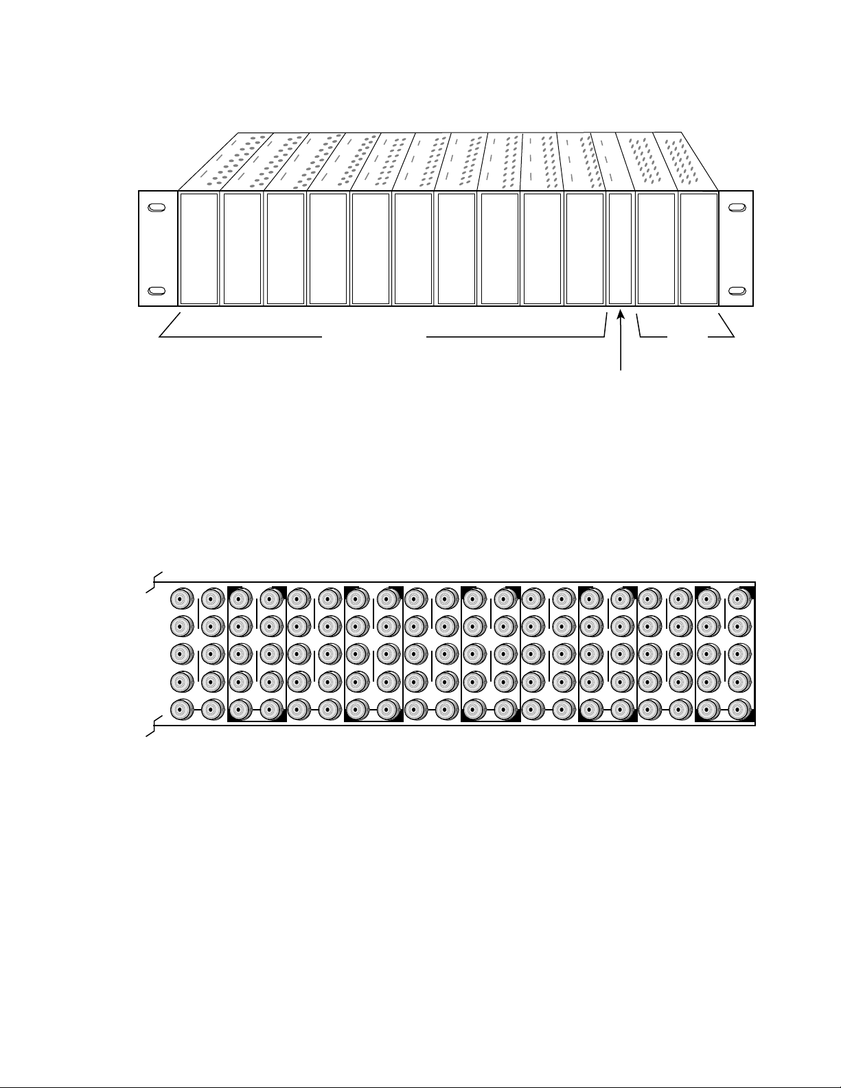
Module Placement in the 8900 Frame
There are ten cell locations in the frame to accommodate either analog or
digital modules. These are the left ten locations. Refer to Figure 1.
The two cells on the right are allocated for the power supplies. For addi-
tional information concerning the Power Supply module, refer to the 8900
Power Supply manual.
The third cell from the right is allocated for the Frame Monitor or Network
Interface module. These modules provide health bus monitoring and
control options.
8900T2-F
Frame
8900TX
Frame
8900TF
Frame
8900TFN
Frame
2 8990ARC Instruction Manual
1.
2.
3.
Figure 1. 8900 Series Frame
Installation
8036-03
10
J1 J2
O
J3 J4
U
T
J5 J6
J7 J8
J9 J10
IN
J1 J2
J2
O
J3 J4
J4
U
J5 J6
J6
J7 J8
J8
J9 J10
IN
Any 8900 Module
Power
Supplies
(only)
Frame Monitor or
Network Interace Module
8900 modules are interchangeable within the module cells. There are 10
BNC connectors in each cell’s I/O group. The functional assignment of
each connector in a group is determined by the module that is placed in
that cell. The maximum number of modules an 8900 frame can accept is
ten. Figure 2 illustrates the rear connector plate for an 8900 Series frame.
Figure 2. 8900 Series Frame Rear Connectors
9
T
8
J1 J2
O
J3 J4
U
T
J5 J6
J7 J8
J9 J10
IN
7
J1 J2
J2
O
J3 J4
J4
U
T
J5 J6
J6
J7 J8
J8
J9 J10
IN
6
J1 J2
O
J3 J4
U
T
J5 J6
J7 J8
J9 J10
IN
5
J1 J2
J2
O
J3 J4
J4
U
T
J5 J6
J6
J7 J8
J8
J9 J10
IN
4
J1 J2
O
J3 J4
U
T
J5 J6
J7 J8
J9 J10
IN
3
J2
J1 J2
O
J4
J3 J4
U
T
J6
J5 J6
J8
J7 J8
J9 J10
IN
2
J1 J2
O
J3 J4
U
T
J5 J6
J7 J8
J9 J10
IN
J1 J2
J3 J4
J5 J6
J7 J8
1
O
U
T
J9 J10
IN
8036-03
Note
At the back of this manual (hard-copy only) are die-cut overlay cards that can
be placed over the rear connector BNCs to identify the specific 8990ARC connector functions.
To install a module in the frame:
Insert the module, connector end first, with the component side of the
module facing to the right and the ejector tab to the top.
Verify that the module connector seats properly against the backplane.
Press the ejector tab in to seat the module in place.
8990ARC Instruction Manual 3
8990ARC SD Aspect Ratio Converter
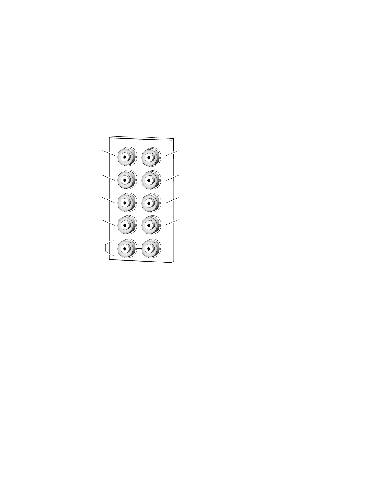
Cabling
Loop-through Input
Connect an input source to one of the loop-through input connectors, J9 or
J10 (see Figure 3). The 8990ARC input accepts SMPTE 259M 8 or 10-bit
component serial digital video. Terminate the unused connector into 75
the signal is not looped to other equipment.
Figure 3. 8990ARC Input, Output and GPI Connectors
Ω
if
Output
Output
Not used
GPI
Loop-through
SDI 270 Mbps Input
Outputs
DAx
J2
J2J1
J3
J5
J7
O
U
T
J9 J10
IN
J4
J6
J8
J4
J6
J8
The 8990ARC provides four 75
Output
Output
Not used
GPI
8036-02
Ω
component video output BNCs (J1
through J4).
The destination equipment should have a 75
through inputs that are terminated into 75
Ω
Ω
input impedance or loop
.
General Purpose Interface (GPI) Connections
BNCs J7 and J8 accept GPI control signals that select one of four user-
defined preset settings that are stored using the onboard configuration con-
trols or the remote GUI controls. The GPI can be used with a user-provided
panel with four latching momentary switches and appropriate resistors.
No tally is provided from the module (see GPI Control on page 12 ).
4 8990ARC Instruction Manual
Power Up
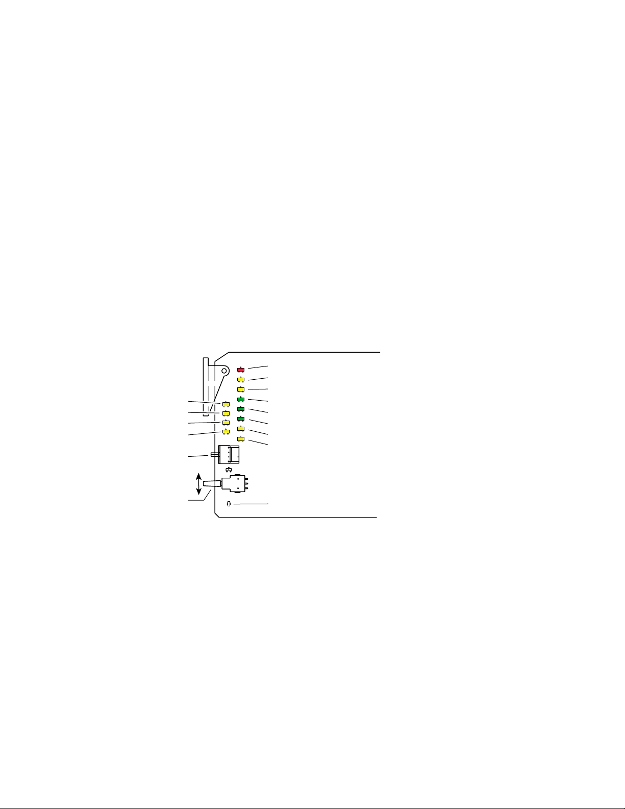
Operation Indicator LEDs
Power Up
The various front LED indicators and configuration switches are illustrated
in Figure 4. Upon power-up, the green PWR LED should light and the
yellow CONF LED should illuminate for the duration of module initialization.
With factory default configuration and a valid input signal connected, the
green PWR LED, and one of the green signal standard LEDs (525 or 625)
should illuminate (refer to Table 2 on page 6 to see the possible operating
indicator combinations).
Video input presence is indicated by the appropriate 525 or 625 LED (indicating a 525-line or 625-line input signal has been detected). The appropriate Mode LED is on.
Mode 1 (yellow)
Mode 2 (yellow)
Mode 3 (yellow)
Mode 4 (yellow)
16-position
Rotary switch
Momentary paddle switch
Figure 4. LEDs and Configuration Switches
Fault (red)
Comm (yellow)
Conf (yellow)
Power (green)
525 (green)
625 (green)
16:9 (yellow)
4:3 (yellow)
8036_05
GND
A red FAULT LED indicates an error situation and, with the previously
described LEDs, can indicate the operational conditions presented in
Table 2 on page 6.
8990ARC Instruction Manual 5

8990ARC SD Aspect Ratio Converter
Table 2. Indicator LEDs and Conditions Indicated
LED Indication Condition
Fault
(red)
COMM
(yellow)
CONF
(yellow)
PWR
(green)
525
(green)
625
(green)
16:9
(yellow)
4:3
(yellow)
Mode 1
(yellow)
Mode 2
(yellow)
Mode 3
(yellow)
Mode 4
(yellow)
On continuously Module has detected internal fault
Short flash
Long flash Location Command received by the module from a remote control system
Short flash Activity present on the frame communication bus
On continuously Module is initializing, changing operating modes or updating firmware
Flashing
On continuously Normal operation, module is powered
On continuously Input signal is 525 standard and present
On continuously Input signal is 625 standard and present
Off Normal operation
EDH errors will cause short flashes. In most applications a few, infrequent EDH
errors will not be of consequence. Continuous EDH errors result in obvious output
signal degradation.
Off No activity on frame communication bus
Off Module is in normal operating mode
Indicates rate of change of paddle switch controlled analog setting. The longer the
switch is held, the more the flashing rate and the change-of-setting rate increases
Off No power to module or module’s DC/DC converter failed
Off Input signal is 625 standard or no signal is present
Off Input signal is 525 standard or no signal is present
Off 4:3 mode is selected
On 16:9 mode is selected
Off 16:9 mode is selected
On 4:3 mode is selected
Off Another mode is selected
On Mode 1 is selected
Off Another mode is selected
On Mode 2 is selected
On Another mode is selected
Off Mode 3 is selected
On
Off Mode 4 is selected
Another mode is selected
Table 3 on page 7 shows the output formating control options and the
resultant output processing for various input signals and controls enabled.
6 8990ARC Instruction Manual

Table 3. Input Combinations and Resulting Outputs
Configuration
WSS Input & Enable
Valid and enabled Any condition Any condition Mode, format WSS control
None or disabled Valid and enabled Any condition Mode, format Video Index control
None or disabled None or disabled Valid and enabled Mode, format GPI control
None or disabled None or disabled None or disabled Mode, format User selected processing
Configuration
Video Index
Input & Enable
GPI Input & Enable
User Selected
Control
Resulting Output Signal
Processing Control
The 8990ARC can be configured locally using onboard switches or
remotely using the 8900NET network interface. The configuration of the
8990ARC determines:
■
Output aspect ratio (16:9/4:3),
■
Display conversion mode see ( Ouput Conversion Modes on page 9 ),
Bypass (no conversion),
■
■
Letterbox for 16:9 output or Pillarbox for 4:3 output,
■
Full-height for 16:9 output or Full-width for 4:3 output,
■
14:9 output,
Position of converted ouputs on the monitor (Tilt for vertical and Pan
■
for horizontal positioning),
■
Enable/disable of Wide Screen Signaling (WSS) allowing control from
video source data,
Number of active lines blanked (None, 1, 2, or 3),
■
■
High or Low vertical resizing filtering – for vertical black/white or
severe chroma transitions,
■
Blanking or passing of vertical ancillary data (VANC),
Enable/disable of video index mode allowing control from data within
■
the video input signal,
■
Enable/disable of GPI control,
Save/Recall of user-defined configurations for each of four GPI and
■
one non-GPI controlled memory register, and
■
Recall of factory default settings.
8990ARC Instruction Manual 7

8990ARC SD Aspect Ratio Converter
8036
06
Onboard Configuration Switches and LEDs
The 8990ARC module can be configured using the rotary and paddle
switches shown in Figure 5. The CONF LED is a configuration status indi-
cator. These three components perform the following:
Function (rotary) switch — Addresses one of 16 possible positions (0
■
through 9 and A through F) to access a desired function for configuration. Not all positions are used (see Table 4).
Note
■
■
Figure 5. Module Configuration Switches and LEDs
JP2
CONF – configuration LED
FUNCTION – rotary switch
The Function switch should be kept in position 0 when not in use to avoid any
inadvertent change in configuration. 0 is an inactive position.
SW1 (paddle) switch — Actuates or selects the desired setting for the
selected function when the switch is held momentarily in either the Up
or Down position.
CONF (configuring) LED — When on, indicates the module is initializing or processing configuration information.
Remote Lockout
Place jumper in
Local
Local &
Remote
JP2
local position to
lock out remote
access.
SW1 – actuator toggle switch
Local On-board Module Configuration
The 8990ARC offers a choice between 4:3 and 16:9 video signal output
formats and one of four picture conversion modes for each format, see
Table 4). The various signal processing and content options are listed in the
table and can also be addressed using the Remote Configuration and Mon-
itoring GUI (see Remote Configuration and Monitoring on page 13 ).
Note
8 8990ARC Instruction Manual
When module power recycles the last setup state is restored. The module
does not revert to a factory or the user default.
_

Configuration
To make a configuration setting:
1. Rotate the Function Switch to the desired function switch position.
2. Move the paddle switch to the up or down position and hold
momentarily to set the desired function.
Table 4. 8990ARC Configuration Functions
Function
Switch
0 -- -- Inactive position
1 16:9 output
2 Decrease (4, 3 ,2
3
4 Disable
5 Decrease (3, 2, 1, 0
6 High
7 Blank
8 Disable
9 Disable
A Recall Save Save/recall GPI 1 mode and current option settings
B Recall Save Save/recall GPI 2 mode and current option settings
C Recall Save Save/recall GPI 3 mode and current option settings
D Recall Save Save/recall GPI 4 mode and current option settings
E Recall Save Save current or recall last saved user settings
F Recall -- Default settings recall
†
Factory Default
Paddle
Switch Up
†
Position left or up
Center is default
†
†
†
†
†
Paddle
Switch Down
4:3 output Selects output aspect ratio
†
, 1) Increase ( 1, 2 †, 3, 4) Steps through four output conversion modes (see below)
Position right or down
Center is default
Enable Enable/disable Wide Screen Signaling Control
†
) Increase (0 †, 1, 2, 3) Steps through choices for active line blanking—none, one, two, or three lines
Low
Pass Blank or pass Vertical Ancillary Data (VANC)
Enable Video index mode control (see Video Index Coding)
Enable General Purpose Interface (GPI) enable/disable
Move picture position on the monitor to one of three positions depending on
applicable mode—Tilt (top, center, bottom) or Pan (left, center, right). Positioning mode is determined by the picture conversion mode selected.
Select High or Low vertical resizing filtering – switch to low to remove ringing in
lines with vertical black/white or severe chroma transitions
Function Description
Ouput Conversion Modes
Function switch position 2 selects one of four output conversion modes for
either 4:3 or 16:9 format:
■ For 4:3 format, 1 = Bypass, 2 = letterbox, 3 = full height, 4 = 14:9, or
■ For 16:9 format, 1 = Bypass, 2 = pillarbox, 3 = full width, 4 = 14:9.
Figure 6 on page 10 and Figure 7 on page 11 illustrate the ouput conver-
sions for both 4:3 and 16:9 formats.
8990ARC Instruction Manual 9

8990ARC SD Aspect Ratio Converter
Figure 6. 4:3 Picture Input to 16:9 Display
INPUT - 4:3
CONVERSION
Mode 1, Bypass
Complete picture with horizontal
stretch
Shift horizontally
Mode 2, Pillarbox
Complete picture with no distortion;
Position left, center, or right (Pan)
Mode 3, Full Width
Top and bottom cropping;
Position top, center, or bottom (Tilt)
= lost picture
Mode 4, 14:9
Top and bottom cropping;
Position left, center, or right (Pan)
Shift
vertically
Shift horizontally
= lost picture
10 8990ARC Instruction Manual

Figure 7. 16:9 Picture Input to 4:3 Display
INPUT - 16:9
CONVERSION
Mode 1, Bypass
Complete picture with vertical
distortion (objects appear taller)
Configuration
Mode 2, Letterbox
Complete picture in Letterbox
format with blanking at top and bottom
Position top, center, or bottom (Tilt)
Mode 3, Full Height
Horizontal cropping
Position left, center, or right (Pan)
= lost picture
Mode 4, 14:9
Vertical blanking
Horizontal cropping
Position top, center, or bottom (Tilt)
= lost picture
Shift
vertically
Shift horizontally
Shift
vertically
8990ARC Instruction Manual 11

8990ARC SD Aspect Ratio Converter
Video Index Coding
In the video input signal, video source data can be inserted (on lines 11 or
324 for 625, on 14 or 277 for 525) to identify the signal line standard and
aspect ratio (per SMPTE RP-186 specification). If this information is present
and the 8990ARC Video Index function is enabled and the module output
mode matches the input, the module will pass the signal as is. If the output
mode does not match, the module will use the selected conversion mode
(2, 3, or 4). The Video Index coding is passed through to the 8990ARC
output unaltered.
Wide Screen Signaling (WSS)
In 625-line systems the video input signal can contain video source data on
line 23 (per specification EN 300 294 v1.3.2). If WSS is enabled, the
8990ARC output conversion mode will be controlled according to this
input data. If Video Index Control is also enabled, the WSS control, when
present, will take precedence. WSS coding is passed through to the
8990ARC output unaltered.
GPI Control
A GPI control input can be connected to either J7 or J8 (not both) on the rear
panel. This is a loop-through input to an A/D converter and a 1.21 KΩ
resistor to +5 V. When the module’s GPI function is enabled, the 8990ARC
software will recognize a GPI input voltage level to select one of four stored
user-defined modes. Looping the input to additional modules allows a
single GPI signal to set them all (up to 10 modules).
The GPI input is created by the application of a parallel resistor between the
coax center and common ground that results in a voltage lower than +5 V
to the A/D converter.
The following voltages (all ±0.4 V) will select the GPI register indicated:
■ 1.25 V = GPI 1
■ 2.08 V = GPI 2
■ 2.92 V = GPI 3
■ 3.75 V = GPI 4
The resistors required for these voltages are shown in Figure 8.
Figure 8. Typical GPI Input Circuit Diagram
Connects to
J7 or J8
Open
1
4
2
3
3570 Ω
1690 Ω
845 Ω
402 Ω
Note:
Resistor tolerance = 1%
Only one GPI input can be used
8036_07
12 8990ARC Instruction Manual

Remote Configuration and Monitoring
8990ARC configuration and monitoring can be performed using the
8900NET interface in 8900TF or TFN frames (see Figure 9). This section
describes the GUI access to the module configuration functions. Refer to
the 8900NET Network Interface Module Instruction Manual for information on setting up and operating the 8900 frame network.
For remote access, make sure the jumper block on the module is set for both
Local and Remote access (Figure 5 on page 8).
Note The physical appearance of the menu displays shown in this manual repre-
sent the use of a particular platform, browser and version of 8900NET
module software. They are provided for reference only. Displays will differ
depending on the type of platform and browser you are using and the version
of the 8900NET software installed in your system.
The 8900 modules can be addressed by clicking on a specific module icon
in the frame status display or on a module name or slot number in the link
list on the left.
Configuration
Figure 9. 8900NET GUI
The Links section lists the frame and its current modules. The selected link's Status
page is first displayed and the sub-list of links for the selection is opened. The sub-list
allows you to select a particular information page for the selected device.
Content display section displays the information page
for the selected frame or module (frame slot icons are also
active links).
8990ARC Instruction Manual 13

8990ARC SD Aspect Ratio Converter
The 8990ARC will indicate a SMPTE Alarm fault on the Frame Status
display for the following alarms:
■ Lack of valid video input
■ Internal Fault
■ Board Failure
Module Configuration Displays
The 8900 GUI provides the following links and displays for the 8990ARC
module (Figure 10):
■ Status and Slot Configuration displays showing status and slot config-
uration information (location and user assigned names),
■ Module Configuration displays, and
■ Software Update display.
The Status and Slot Configuration displays operate in the same manner for
all remote controllable 8900 modules. Refer to the 8900NET manual for
more information on these displays. Some functions listed may not be supported by a particular module. These will be indicated as not supported.
Figure 10. 8990ARC Display Links
Status and Slot Configuration Displays
Module Configuration Displays
Software Update Display
Software Update Display
The Software Update display allows you to download new software versions for the module. Refer to the 8900NET manual and the Grass Valley
Group web site at http://www.grassvalleygroup.com for complete details
and new software versions.
Module Configuration Displays
This section discusses the Module Configuration Displays used to set
parameters required for 8990ARC module operation. You may select
output format, control options, and signal options. Press the
activate the selections.
APPLY button to
14 8990ARC Instruction Manual

Use
T
his
Link
Configuration
Settings
The Settings display (Figure 11) allows you to:
■ Select Output Format – 4:3 or 16:9,
■ Select Conversion Mode – output picture ratio options,
■ Select Tilt or Pan – Tilt appears in modes that allow vertical position
adjustment, Pan appears in modes that allow horizontal position
adjustment,
■ Enable/disable Video Index control (see Video Index Coding on page 12),
■ Enable/disable Wide Screen Signaling (see Wide Screen Signaling (WSS)
on page 12),
■ Enable GPI control (see GPI Control on page 12),
■ Pass/blank vertical ancillary data (VANC),
■ Select active line blanking option, and
■ Select high or low V Process BW (vertical resizing) filter – switch to low
to remove ringing in lines with vertical black/white or severe chroma
transitions (see Vertical Resize Filtering on page 21).
Positioning
mode (Pan
or Tilt)
changes with
output format
and conversion
mode
Figure 11. Settings Display
4:3 16:9
or
Tilt Pan
or
8990ARC Instruction Manual 15

8990ARC SD Aspect Ratio Converter
T
Save/Recall Settings Display
The 8990ARC provides five storage registers to save module configuration
Use
his
Link
settings for access through standard local and remote control or through
the GPI interface (see Figure 12). Current module configuration settings are
displayed above the recall/save buttons. Factory default settings can be
recalled using the
Figure 12. Save/Recall Display
Recall Defaults button.
16 8990ARC Instruction Manual

Specifications
Specifications
Table 5. 8990ARC Specifications
Parameter Value
SDI Input
Signal type SMPTE 259M-C or EBU tech 3267, 8 or 10-bit serial digital component video
Number of inputs 1 loop-through
Connector type 75 Ω BNC
Return loss > 15 dB, 5 to 270 MHz
Max input cable lengthl 225 m (984 ft) of Belden 8281 or equivalent
SDI Outputs
Number of outputs 4
Connector type 75 Ω BNC
Signal type SMPTE 259M-C or EBU tech 3267
Output impedance 75 Ω
Return loss > 15 dB, 5 to 270 MHz
Signal Processing
Signal path 12-bit processing internally then rounded and truncated to 10 bits
525/625 selection Automatic
Aspect ratio selection 16:9 to 4:3, 4:3 to 16:9, manual or automatic if video index or WSS input is
enabled
Modes 16:9 to 4:3 conversion • No processing
• Letter-box (no loss)
• Full height (h-crop)
• 14:9 sub-image (some h-crop, less than full height)
Modes 4:3 to 16:9 conversion • No processing
• Side panels (no loss)
• Full width (v-crop)
• 14:9 sub-image (some v-crop, less than full width)
Horizontal position Left/center/right justified output (shrink) or input (magnify)
Vertical position Top/center/bottom justified output (shrink) or input (magnify)
Horizontal ancillary data All horizontal embedded ancillary data (HANC) passed to output
Hot switch handling Module will handle input signal hot switched between synchronous signals that
are timed within the same line without causing glitches in the output stream
Switching line processing None
Vertical interval blanking Vertical interval active line time data optionally replaced by black or blanking –
20 or 21 lines blanked for 525; 25 lines blanked for 625 signals
Active line blanking Top and bottom 0, 1, 2, or 3 lines
In 525: Field 1 – 21 to 23 and 263 to 261; Field 2 – 20 to 22 and 262 to 260
In 625: Field 1 – 23 to 25 and 310 to 308; Field 2 – 336 to 338 and 623 to 621
Output signal EDH Error Detection Handling (EDH) check-words per SMPTE RP 165 inserted in
output signal
Performance
Electrical length 75.25 lines all modes
Response to input signal loss Output signal is invalid
8990ARC Instruction Manual 17

8990ARC SD Aspect Ratio Converter
Table 5. 8990ARC Specifications - (continued)
Parameter Value
Environmental
Frame temperature range 0 to 45 degrees C
Operating humidity range 0 to 90% non-condensing
Non-operating temperature - 10 to 70 degrees C
Mechanical
Frame type 8900 Series
Power Requirements
Supply voltage + 12 V
Power consumption 4.75 Watts
18 8990ARC Instruction Manual

Service
Service
The 8990ARC Digital to Analog Converter modules make extensive use of
surface-mount technology and programmed parts to achieve compact size
and adherence to demanding technical specifications. Circuit modules
should not be serviced in the field unless otherwise directed by Customer
Service.
If your module is not operating correctly, proceed as follows:
■ Check frame and module power and signal present LEDs.
■ Verify power at the voltage tespoints (see Figure 14) and check Fuse F1
if no voltage is detected.
■ Check for presence and quality of input signals.
■ Verify that source equipment is operating correctly.
■ Check cable connections.
■ Check output connections for correct I/O mapping (correct input con-
nector is used for the corresponding channel output).
JP1
GND
Refer to Figure 4 for the location of PWR LED and Table 2 on page 6 for
proper LED indications.
If the module is still not operating correctly, replace it with a known good
spare and return the faulty module to a designated Grass Valley repair
depot. Call your Grass Valley representative for depot location.
Figure 13. Refer to Contacting Grass Valley Group at the front of this
document for the Grass Valley Customer Service Information number.
Figure 14. Fuse and Voltage Testpoint Locations
Voltage Testpoints
pin 3, +3 V
pin 5, -5 V
JP1
F1
Fuse: 2 A FAST
125 V
8036_08
8990ARC Instruction Manual 19

8990ARC SD Aspect Ratio Converter
Functional Description
Refer to the block diagram in Figure 15 while reading the following functional description.
Figure 15. 8990ARC Block Diagram
ANC Bypass
270 Mb input
27 MHz clock
and PLL
Processor
and
Power
input h-lock
27MHz
Input Y & C
FIFOs
Processor I/F and Control FPGA
Coefficient loading
and control
Horiz & Vert
Polyphase
Filter
H & V re-size processing
Input and Ancillary Data Processing
The input signal is deserialized and enters the control Field Programmable
Gate Array (FPGA). Sync is detected and is used to H-lock the system 27
MHz clock. All horizontal and vertical interval data is routed through the
ancillary date (ANC) bypass FIFO to delay match the re-sized active
picture data and is multiplexed back, with the re-sized data, to the parallel
data output. This output is serialized and output through 4 buffers and
connectors.
270 Mb
Output
GPI Input A/D
Output Y & C
FIFOs
20 8990ARC Instruction Manual

Active Picture Processing
The active picture portion is routed through the H & V re-sizing portion
shown. Depending on the mode and input format selected, H and V will be
scaled up or down. The maximum delay for this processing is required for
vertical magnification, where the starting position of the output will be at
last position in the input picture. The worst case is 4:3 input and mode 3
(full-width) with the vertical position set at the bottom of the field. In all
modes, the overall delay will be fixed at this worst case for each line rate.
H & V Re-sizing Algorithm
Scaling up (magnify) creates more pixels or lines in a selected region than
is available in the input and therefore requires a horizontal or vertical position adjustment. It is accomplished by periodically holding off the reading
of data from the input FIFO, while re-computing a new pixel/line in its corresponding poly-phase filter.
Functional Description
Scaling down (shrink) decimates pixels or lines from the entire source
image and results in a blanked region in the output, which is adjusted
using the horizontal or vertical position adjustment. It is accomplished by
periodically holding off the writing of data to the output FIFO, while recomputing a new pixel/line in its corresponding poly-phase filter.
In modes 2 and 3 only one operation is performed, H or V scale up or
down. In mode 4, the 14:9 sub-image both scaling up and scaling down are
done independently and simultaneously.
Vertical Resize Filtering
All the poly-phase filters used for vertical magnification or shrink have
maximum bandwidth. Video sources with high contrast or chroma saturated horizontal edges will produce some filter ringing within a few lines
above and below the edge. One example of such an edge is contained in the
SMPTE color bar test pattern. If this effect needs to be eliminated, then
linear-interpolators can be used in these vertical processing modes in the V
Process BW configuration selection. The consequence of this selection is
having a reduced vertical bandwidth.
Video Index Information Coding Support
Video source data can be inserted on lines 11 or 324 in 625 line or 14 and 277
in 525 line systems per SMPTE RP-186 specification. The very first section
of this coding region, Class 1.1, data octet 1, encodes options on the source
of being 525/625 line and 4x3 or 16x9 format. If the input to the 8990ARC
8990ARC Instruction Manual 21

8990ARC SD Aspect Ratio Converter
contains this section of coding and the Video Index Control function is
enabled, the mode will automatically change to 1 (no processing) if the
input format and selected output format are the same. It will revert to the
previous, 2 through 4 selection when either the input format changes or the
user changes the desired output format.
22 8990ARC Instruction Manual

Index
Numerics
525 LED 5, 6
625 LED 5, 6
B
backplane 3
block diagram 20
C
COMM LED 6
CONF (configuring) LED 5, 6, 8
configuration
local on-board
remote 13
connectors 3
input 4
input/output 4
controller module 2
8
E
environmental 18
fuse 19
G
GUI 13, 14
I
impedance 4
indicators 5
input 17
loopthrough 4
specification 17
L
loop-through 4
M
MAN LED 5
module
controller
installation 2
power supply 2
slots 3
2
F
factory default 5, 9
fault 5
FAULT LED 6
fault report 14
formats
local setup
frame 2, 18
frame capacity 2
frame status display 13
Function rotary switch 8, 9
8990ARC Instruction Manual Index-1
9
N
network 13
O
operational modes 5
outputs 17
connectors 4
specification 17
termination 4
overlay 3

P
paddle switch 8
performance 17
power 18
power supply 2
PWR LED 5, 6
R
repair depot 19
S
SMPTE alarm 14
software update 14
specifications 17
switches (onboard) 8
sync output 4
T
termination 4
troubleshooting 19
V
video outputs
cabling
voltage (supply) 18
voltage tespoints 19
4
Index-2 8990ARC Instruction Manual

8990ARC SD Aspect Ratio Converter
Rear Connector Overlay
Fold along vertical lines to break perforations, then tear to separate vertical pairs.
Fold FoldFold FoldFold Fold
J9
J1
J5
J7
8990ARC
OUT OUT
OUT OUT J3
NOT
USED
GPI
INPUT
IN
8990ARC
J2
J4
J6
J8
J10
J9
J1
J5
J7
8990ARC
OUT OUT
OUT OUT J3
NOT
USED
GPI
INPUT
IN
8990ARC
J2
J4
J6
J8
J10
J9
J1
J5
J7
8990ARC
OUT OUT
OUT OUT J3
NOT
USED
GPI
INPUT
IN
8990ARC
J2
J4
J6
J8
J10
J9
J1
J5
J7
OUT OUT
OUT OUT J3
NOT
USED
GPI
INPUT
IN
J2
J4
J6
J8
J10
J9
J1
J5
J7
OUT OUT
OUT OUT J3
NOT
USED
GPI
INPUT
IN
J2
J4
J6
J8
J10
J9
J1
J5
J7
Fold FoldFold FoldFold Fold
OUT OUT
OUT OUT J3
NOT
USED
GPI
INPUT
IN
J2
J4
J6
J8
J10

8990ARC SD Aspect Ratio Converter
contains this section of coding and the Video Index Control function is
enabled, the mode will automatically change to 1 (no processing) if the
input format and selected output format are the same. It will revert to the
previous, 2 through 4 selection when either the input format changes or the
user changes the desired output format.
22 8990ARC Instruction Manual

8990ARC SD Aspect Ratio Converter
Rear Connector Overlay
Fold along vertical lines to break perforations, then tear to separate vertical pairs.
Fold FoldFold FoldFold Fold
J9
J1
J5
J7
8990ARC
OUT OUT
OUT OUT J3
NOT
USED
GPI
INPUT
IN
8990ARC
J2
J4
J6
J8
J10
J9
J1
J5
J7
8990ARC
OUT OUT
OUT OUT J3
NOT
USED
GPI
INPUT
IN
8990ARC
J2
J4
J6
J8
J10
J9
J1
J5
J7
8990ARC
OUT OUT
OUT OUT J3
NOT
USED
GPI
INPUT
IN
8990ARC
J2
J4
J6
J8
J10
J9
J1
J5
J7
OUT OUT
OUT OUT J3
NOT
USED
GPI
INPUT
IN
J2
J4
J6
J8
J10
J9
J1
J5
J7
OUT OUT
OUT OUT J3
NOT
USED
GPI
INPUT
IN
J2
J4
J6
J8
J10
J9
J1
J5
J7
Fold FoldFold FoldFold Fold
OUT OUT
OUT OUT J3
NOT
USED
GPI
INPUT
IN
J2
J4
J6
J8
J10

8990ARC SD Aspect Ratio Converter
contains this section of coding and the Video Index Control function is
enabled, the mode will automatically change to 1 (no processing) if the
input format and selected output format are the same. It will revert to the
previous, 2 through 4 selection when either the input format changes or the
user changes the desired output format.
22 8990ARC Instruction Manual
 Loading...