

8990ARC
SD ASPECT RATIO CONVERTER MODULE
Instruction Manual
SOFTWARE VERSION 3.0.0
071803601
DECEMBER 2004

Contacting Grass Valley
Region Voice Fax Address Web Site
North America (800) 547-8949
Support: 530-478-4148
Pacific Operations +852-2585-6688
Support: 852-2585-6579
U.K., Asia, Middle East +44 1753 218 777 +44 1753 218 757
France +33 1 45 29 73 00
Germany, Europe +49 6150 104 782 +49 6150 104 223
Copyright © Thomson Broadcast and Media Solutions All rights reserved.
Grass Valley Web Site
Sales: (530) 478-3347
Support: (530) 478-3181
+852-2802-2996
Grass Valley
P.O. Box 599000
Nevada City, CA 959597900 USA
www.thomsongrassvalley.com
The www
Online User Documentation
.thomsongrassvalley.com web site offers the following:
— Current versions of product catalogs, brochures,
data sheets, ordering guides, planning guides, manuals, and release notes
in .pdf format can be downloaded.
FAQ Database
— Solutions to problems and troubleshooting efforts can be
found by searching our Frequently Asked Questions (FAQ) database.
Software Downloads
— Software updates, drivers, and patches can be down-
loaded.
2 8990ARC Instruction Manual

Contents
Preface
. . . . . . . . . . . . . . . . . . . . . . . . . . . . . . . . . . . . . . . . . . . . . . . . . . . . . . . . . . . . . . . . . . . . . 5
About This Manual . . . . . . . . . . . . . . . . . . . . . . . . . . . . . . . . . . . . . . . . . . . . . . . . . . . . . 5
Introduction . . . . . . . . . . . . . . . . . . . . . . . . . . . . . . . . . . . . . . . . . . . . . . . . . . . . . . . . . . . 7
Installation . . . . . . . . . . . . . . . . . . . . . . . . . . . . . . . . . . . . . . . . . . . . . . . . . . . . . . . . . . . . 8
Frame Capacity . . . . . . . . . . . . . . . . . . . . . . . . . . . . . . . . . . . . . . . . . . . . . . . . . . . . . . 8
Module Placement in the 8900 Frame. . . . . . . . . . . . . . . . . . . . . . . . . . . . . . . . . . . . 8
Cabling . . . . . . . . . . . . . . . . . . . . . . . . . . . . . . . . . . . . . . . . . . . . . . . . . . . . . . . . . . . . 10
Loop-through Input. . . . . . . . . . . . . . . . . . . . . . . . . . . . . . . . . . . . . . . . . . . . . . . . 10
Outputs . . . . . . . . . . . . . . . . . . . . . . . . . . . . . . . . . . . . . . . . . . . . . . . . . . . . . . . . . . 10
General Purpose Interface (GPI) Connections. . . . . . . . . . . . . . . . . . . . . . . . . . 10
Power Up . . . . . . . . . . . . . . . . . . . . . . . . . . . . . . . . . . . . . . . . . . . . . . . . . . . . . . . . . . . . 12
Operation Indicator LEDs . . . . . . . . . . . . . . . . . . . . . . . . . . . . . . . . . . . . . . . . . . . . 12
Configuration. . . . . . . . . . . . . . . . . . . . . . . . . . . . . . . . . . . . . . . . . . . . . . . . . . . . . . . . . 14
Output Format Control Summary . . . . . . . . . . . . . . . . . . . . . . . . . . . . . . . . . . . . . 14
Output Aspect Ratio . . . . . . . . . . . . . . . . . . . . . . . . . . . . . . . . . . . . . . . . . . . . . . . 14
Vertical Resizing. . . . . . . . . . . . . . . . . . . . . . . . . . . . . . . . . . . . . . . . . . . . . . . . . . . 17
Output Conversion Modes. . . . . . . . . . . . . . . . . . . . . . . . . . . . . . . . . . . . . . . . . . 17
Video and VBI Line Handling . . . . . . . . . . . . . . . . . . . . . . . . . . . . . . . . . . . . . . . 18
Video Index Coding . . . . . . . . . . . . . . . . . . . . . . . . . . . . . . . . . . . . . . . . . . . . . . . . . 20
Modified Video Index Coding . . . . . . . . . . . . . . . . . . . . . . . . . . . . . . . . . . . . . . . 21
Custom WSS/Video Index Coding. . . . . . . . . . . . . . . . . . . . . . . . . . . . . . . . . . . 23
Wide Screen Signaling (WSS) . . . . . . . . . . . . . . . . . . . . . . . . . . . . . . . . . . . . . . . . . 24
WSS Line Selection. . . . . . . . . . . . . . . . . . . . . . . . . . . . . . . . . . . . . . . . . . . . . . . . . 24
Standard Wide Screen Signaling . . . . . . . . . . . . . . . . . . . . . . . . . . . . . . . . . . . . . 24
Modified Wide Screen Signaling . . . . . . . . . . . . . . . . . . . . . . . . . . . . . . . . . . . . . 25
Custom Wide Screen Signaling . . . . . . . . . . . . . . . . . . . . . . . . . . . . . . . . . . . . . . 25
GPI Control. . . . . . . . . . . . . . . . . . . . . . . . . . . . . . . . . . . . . . . . . . . . . . . . . . . . . . . . . 25
Configuration Summary. . . . . . . . . . . . . . . . . . . . . . . . . . . . . . . . . . . . . . . . . . . . . . 26
Newton Pan/Tilt Control . . . . . . . . . . . . . . . . . . . . . . . . . . . . . . . . . . . . . . . . . . . 27
Onboard Configuration Switches and LEDs . . . . . . . . . . . . . . . . . . . . . . . . . . . . . 29
Local On-board Module Configuration . . . . . . . . . . . . . . . . . . . . . . . . . . . . . . . 30
Remote Configuration and Monitoring . . . . . . . . . . . . . . . . . . . . . . . . . . . . . . . . . 31
8900NET Module Information . . . . . . . . . . . . . . . . . . . . . . . . . . . . . . . . . . . . . . . 31
Newton Control Panel Configuration. . . . . . . . . . . . . . . . . . . . . . . . . . . . . . . . . 31
Web Browser Interface . . . . . . . . . . . . . . . . . . . . . . . . . . . . . . . . . . . . . . . . . . . . . 32
8990ARC Links and Web Pages. . . . . . . . . . . . . . . . . . . . . . . . . . . . . . . . . . . . . . 34
Status Monitoring . . . . . . . . . . . . . . . . . . . . . . . . . . . . . . . . . . . . . . . . . . . . . . . . . . . . . 43
LEDs . . . . . . . . . . . . . . . . . . . . . . . . . . . . . . . . . . . . . . . . . . . . . . . . . . . . . . . . . . . . . . 43
Frame Alarm . . . . . . . . . . . . . . . . . . . . . . . . . . . . . . . . . . . . . . . . . . . . . . . . . . . . . . . 44
Web Browser Interface . . . . . . . . . . . . . . . . . . . . . . . . . . . . . . . . . . . . . . . . . . . . . . . 44
SNMP Reporting . . . . . . . . . . . . . . . . . . . . . . . . . . . . . . . . . . . . . . . . . . . . . . . . . . 45
Specifications . . . . . . . . . . . . . . . . . . . . . . . . . . . . . . . . . . . . . . . . . . . . . . . . . . . . . . . . . 46
Service. . . . . . . . . . . . . . . . . . . . . . . . . . . . . . . . . . . . . . . . . . . . . . . . . . . . . . . . . . . . . . . 49
Functional Description . . . . . . . . . . . . . . . . . . . . . . . . . . . . . . . . . . . . . . . . . . . . . . . . . 50
Input and Ancillary Data Processing . . . . . . . . . . . . . . . . . . . . . . . . . . . . . . . . . . . 50
8990ARC Instruction Manual 3

Contents
Active Picture Processing . . . . . . . . . . . . . . . . . . . . . . . . . . . . . . . . . . . . . . . . . . . . 50
H & V Re-sizing Algorithm. . . . . . . . . . . . . . . . . . . . . . . . . . . . . . . . . . . . . . . . . . . 51
Vertical Resize Filtering. . . . . . . . . . . . . . . . . . . . . . . . . . . . . . . . . . . . . . . . . . . . . . 51
Video Index Information Coding Support . . . . . . . . . . . . . . . . . . . . . . . . . . . . . . 51
Index
. . . . . . . . . . . . . . . . . . . . . . . . . . . . . . . . . . . . . . . . . . . . . . . . . . . . . . . . . . . . . . . . . . . . . . 53
4 8990ARC Instruction Manual

Preface
About This Manual
This manual describes the features of a specific module of the Gecko 8900
Signal Processing System. As part of this module family, it is subject to
Safety and Regulatory Compliance described in the Gecko 8900 Series
frame and power supply documentation (see the Gecko 8900 Frames Instruc-
tion Manual
).
8990ARC Instruction Manual 5

Preface
6 8990ARC Instruction Manual

8990ARC SD Aspect Ratio Converter
Introduction
The 8990ARC converts between standard (4:3) and widescreen (16:9) SD
video formats. Flexible aspect ratio control is provided on the module’s
front panel and through remote control using the 8900 web browser graphical user interface (GUI) and the Newton Control Panel.
The 8990ARC is compact and fits in the 8900 frame which holds up to 10
modules in 2 RU. It supports 270 Mb serial digital video with outputs referenced from the input signal.
Key features include:
• 270 Mb component serial digital input and output,
•Module is hot-swappable,
•Module settings are stored in non-volatile memory,
•Automatic 525/625 line selection based on video input,
• Passes horizontal ancillary data (HANC),
• Passes or blanks vertical interval ancillary data (VANC),
• Standard, modified, and custom Video Index Coding and Wide Screen
Signaling (WSS) with selectable WSS line,
•GPI (general purpose interface) input can recall one of four
user-defined preset settings,
• Selection of top and bottom one, two, or three active video lines as data
lines, and
•Remote control and monitoring through the 8900 frame ethernet I/F
and Newton Control Panel (with 8900NET module running software
version 3.2.0 and later).
8990ARC Instruction Manual 7

Installation
Installation
Frame Capacity
Installation of the 8990ARC module is a process of:
• Placing the module in the selected frame slot, and
•Cabling and terminating signal ports.
The 8990ARC module can be plugged in and removed from an 8900 Series
frame with power on. When power is applied to the module, LED indicators reflect the initialization process (see
The maximum number of 8900 modules allowed in a frame is determined
by frame cooling capacity. Table 1 provides the power capacity, cooling
capacity, and maximum module count for the 8990ARC in each frame type.
Power Up
on page 12).
Table 1. Power, Cooling, and Module Capacity of 8900 Frames
Capacity Calculated
Power (W) 60 60 100 100 100
Recommended Module Cooling (W) 30 60 30 90 90
8990ARC Modules 6 10 6 10 10
Note
Module capacity figures assume no other modules are in the frame.
If the maximum number of modules a frame can handle is less than ten,
provide as much space between the modules as possible.
8900T2
Frame
Module Placement in the 8900 Frame
There are ten cell locations in the frame to accommodate either analog or
digital modules. These are the left ten locations. Refer to Figure 1 on page 9.
The two cells on the right are allocated for the power supplies. For additional information concerning the Power Supply module, refer to the 8900
Power Supply manual.
The third cell from the right is allocated for the Frame Monitor or Network
Interface module. These modules provide health bus monitoring and
control options.
8900T2-F
Frame
8900TX
Frame
8900TF
Frame
8900TFN
Frame
8 8990ARC Instruction Manual
1.
2.
3.
Figure 1. 8900 Series Frame
Installation
8036_04
10
J1 J2
O
J3 J4
U
T
J5 J6
J7 J8
J9 J10
IN
9
J2
J1 J2
O
J4
J3 J4
U
T
J6
J5 J6
J8
J7 J8
J9 J10
IN
Any Gecko/8900 Module
Power
Supplies
Frame Controller or
8900NET Network
Interface Module
8900 modules are interchangeable within the module cells. There are 10
BNC connectors in each cell’s I/O group. The functional assignment of
each connector in a group is determined by the module that is placed in
that cell. The maximum number of modules an 8900 frame can accept is ten.
Figure 2 illustrates the rear connector plate for an 8900 Series frame.
Figure 2. 8900 Series Frame Rear Connectors
8
J1 J2
O
J3 J4
U
T
J5 J6
J7 J8
J9 J10
IN
7
J1 J2
J2
O
J3 J4
J4
U
T
J5 J6
J6
J7 J8
J8
J9 J10
IN
6
J1 J2
O
J3 J4
U
T
J5 J6
J7 J8
J9 J10
IN
5
J1 J2
J2
O
J3 J4
J4
U
T
J5 J6
J6
J7 J8
J8
J9 J10
IN
4
J1 J2
O
J3 J4
U
T
J5 J6
J7 J8
J9 J10
IN
3
J2
J1 J2
O
J4
J3 J4
U
T
J6
J5 J6
J8
J7 J8
J9 J10
IN
2
J1 J2
O
J3 J4
U
T
J5 J6
J7 J8
J9 J10
IN
1
J1 J2
O
J3 J4
U
T
J5 J6
J7 J8
J9 J10
IN
8036-03
To install a module in the frame:
Insert the module, connector end first, with the component side of the
module facing to the right and the ejector tab to the top.
Verify that the module connector seats properly against the backplane.
Press the ejector tab in to seat the module in place.
8990ARC Instruction Manual 9
Installation
Cabling
Note
At the back of this manual (hard-copy only) are die-cut overlay cards that can
be placed over the rear connector BNCs to identify the specific 8990ARC connector functions.
Loop-through Input
Connect an input source to one of the loop-through input connectors, J9 or
J10 (see Figure 3). The 8990ARC input accepts SMPTE 259M-C or EBU tech
3267 8- or 10-bit component serial digital video. Terminate the unused connector into 75
Figure 3. 8990ARC Input, Output and GPI Connectors
Output
Output
Not used
Ω if the signal is not looped to other equipment.
GPI
J3
J5
DAx
O
U
T
J2
J4
J6
J2J1
J4
J6
Output
Output
Not used
GPI
J8
J8
Loop-through
SDI 270 Mbps Input
J7
J9 J10
IN
Outputs
The 8990ARC provides four 75 Ω component video output BNCs (J1
through J4).
The destination equipment should have a 75
through inputs that are terminated into 75
General Purpose Interface (GPI) Connections
BNCs J7 and J8 accept GPI control signals that select one of four
user-defined preset settings that are stored using the onboard configuration controls or the remote GUI controls. The GPI can be used with a
user-provided panel with four latching momentary switches and appropriate resistors. No tally is provided from the module.
8036-02
Ω input impedance or loop
Ω .
10 8990ARC Instruction Manual
Installation
GPI Control
The GPI control input at BNCs J7 or J8 (not both) on the rear panel is a
Ω
loop-through input to an A/D converter and a 1.21 K
When the module’s GPI function is enabled, the 8990ARC software will
recognize a GPI input voltage level to select one of four stored user-defined
modes. Looping the input to additional modules allows a single GPI signal
to set them all (up to 10 modules).
The GPI input is created by the application of a parallel resistor between
the coax center and common ground that results in a voltage lower than
+5 V to the A/D converter.
The following voltages (all ±0.4 V) will select the GPI register indicated:
• 1.25 V = GPI 1
• 2.08 V = GPI 2
resistor to +5 V.
• 2.92 V = GPI 3
• 3.75 V = GPI 4
The resistors required for these voltages are shown in Figure 4.
Figure 4. Typical GPI Input Circuit Diagram
Note:
Resistor tolerance = 1%
Only one GPI input can be used
Connects to
J7 or J8
Open
1
2
3
4
1690 Ω
3570 Ω
402 Ω
845 Ω
8036_07
8990ARC Instruction Manual 11
Power Up
Power Up
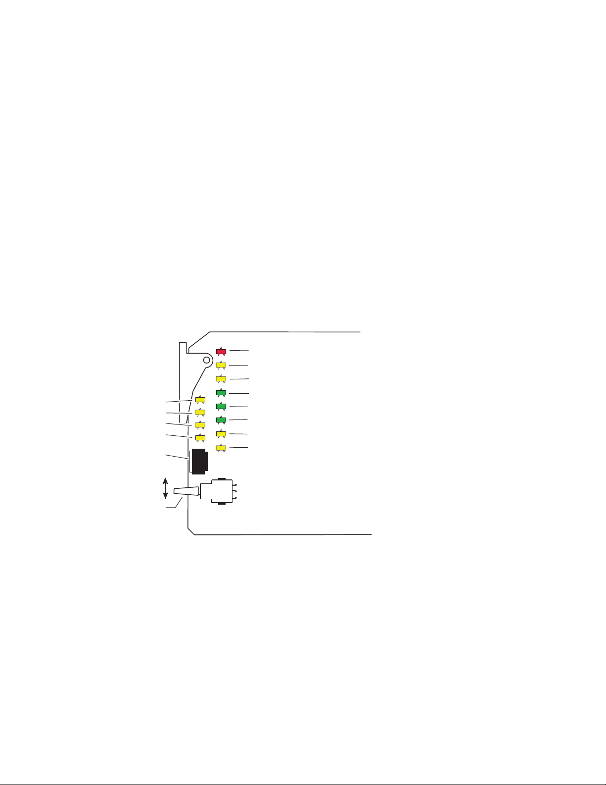
Operation Indicator LEDs
The various front LED indicators and configuration switches are illustrated
in Figure 5. Upon power-up, the green PWR LED should light and the
yellow CONF LED should illuminate for the duration of module initialization.
With factory default configuration and a valid input signal connected, the
green PWR LED, and one of the green signal standard LEDs (525 or 625)
should illuminate (refer to Table 2 on page 13 to see the possible operating
indicator combinations).
Video input presence is indicated by the appropriate 525 or 625 LED (indicating a 525-line or 625-line input signal has been detected). The appropriate Mode LED is on.
Mode 1 (yellow)
Mode 2 (yellow)
Mode 3 (yellow)
Mode 4 (yellow)
16-position
Rotary switch
Momentary paddle switch
Figure 5. LEDs and Configuration Switches
FAULT (red)
COMM (yellow)
CONF (yellow)
PWR (green)
525 (green)
625 (green)
16:9 (yellow)
4:3 (yellow)
8036_05r1
12 8990ARC Instruction Manual

A red FAULT LED indicates an error situation and, with the previously
described LEDs, can indicate the operational conditions presented in
Table 2.
Table 2. Indicator LEDs and Conditions Indicated
LED Indication Condition
Off Normal operation
FAULT
(red)
COMM
(yellow)
CONF
(yellow)
PWR
(green)
525
(green)
625
(green)
16:9
(yellow)
4:3
(yellow)
Mode 1
(yellow)
Mode 2
(yellow)
Mode 3
(yellow)
Mode 4
(yellow)
On continuously Module has detected internal fault
Short flash
Off No activity on frame communication bus
Long flash Location Command received by the module from a remote control system
Short flash Activity present on the frame communication bus
Off Module is in normal operating mode
On continuously Module is initializing, changing operating modes or updating firmware
Flashing
Off No power to module or module’s DC/DC converter failed
On continuously Normal operation, module is powered
Off Input signal is 625 standard or no signal is present
On continuously Input signal is 525 standard and present
Off Input signal is 525 standard or no signal is present
On continuously Input signal is 625 standard and present
Off 4:3 mode is selected
On 16:9 mode is selected
Off 16:9 mode is selected
On 4:3 mode is selected
Off Another mode is selected
On Mode 1 is selected
Off Another mode is selected
On Mode 2 is selected
On Another mode is selected
Off Mode 3 is selected
On
Off Mode 4 is selected
EDH errors will cause short flashes. In most applications a few, infrequent EDH
errors will not be of consequence. Continuous EDH errors result in obvious output
signal degradation.
Indicates rate of change of paddle switch controlled analog setting. The longer the
switch is held, the more the flashing rate and the change-of-setting rate increases
Another mode is selected
Power Up
8990ARC Instruction Manual 13

Configuration
Configuration
The 8990ARC can be configured locally using onboard switches or
remotely using the 8900NET GUI interface or the Newton Control Panel. A
summary of all functions available with each control type along with the
ranges and default values for each parameter is given in Table 8 on page 26.
The configuration of the 8990ARC determines:
•Output aspect ratio (16:9/4:3),
•Display conversion modes: (see
• Bypass (no conversion),
• Pillarbox for 16:9 output or Letterbox for 4:3 output,
• Full Width for 16:9 output or Full Height for 4:3 output,
• 14:9 output,
•High or Low vertical resizing filtering – for vertical black/white or
severe chroma transitions,
• Position of converted outputs on the monitor (Tilt for vertical and Pan
for horizontal positioning),
• Blanking or passing of vertical ancillary data (VANC),
•Number of active video lines selected as data lines (None, 1, 2, or 3),
• Enable one of three Video Index Control modes allowing control from
data within the video input signal,
• Enable one of three Wide Screen Signaling (WSS) Control modes
allowing control from video source data and selection of WSS line (lines
13-27),
• Enable/disable of GPI control,
Output Conversion Modes
on page 17),
• Save/Recall of user-defined configurations for each of four GPI and
one non-GPI controlled memory register, and
•Recall of factory default settings.
Output Format Control Summary
The output format from the module can be resized by selecting an aspect
ratio, a conversion mode, and setting vertical resizing.
Output Aspect Ratio
The output aspect ratio can be selected with the web page, Newton control
panel, local controls, or though the GPI registers as either 16:9 or 4:3.
Figure 6 on page 15 and Figure 7 on page 16 illustrate the output conver-
sions for both 4:3 and 16:9 formats.
14 8990ARC Instruction Manual

Figure 6. 4:3 Picture Input to 16:9 Conversion Options
INPUT - 4:3
CONVERSION
Mode 1, Bypass
Complete picture with horizontal
stretch
Configuration
Mode 2, Pillarbox
Complete picture with no distortion;
Position left, center, or right (Pan)
Mode 3, Full Width
Top and bottom cropping;
Position top, center, or bottom (Tilt)
= lost picture
Shift horizontally
Shift
vertically
Shift horizontally
Mode 4, 14:9
Top and bottom cropping;
Position left, center, or right (Pan)
= lost picture
8990ARC Instruction Manual 15

Configuration
Figure 7. 16:9 Picture Input to 4:3 Conversion Options
INPUT - 16:9
CONVERSION
Mode 1, Bypass
Complete picture with vertical
distortion (objects appear taller)
Mode 2, Letterbox
Complete picture in Letterbox
format with blanking at top and bottom
Position top, center, or bottom (Tilt)
Mode 3, Full Height
Horizontal cropping
Position left, center, or right (Pan)
= lost picture
Mode 4, 14:9
Vertical blanking
Horizontal cropping
Position top, center, or bottom (Tilt)
= lost picture
Shift
vertically
Shift horizontally
Shift
vertically
8036_09
16 8990ARC Instruction Manual

Vertical Resizing
The V Process BW control adjusts vertical sizing to correct filter ringing
above and below the edge on video sources with high contrast or chroma
saturated horizontal edges. Select
tical black/white or severe chroma transitions.
Output Conversion Modes
One of four output conversion modes for either 4:3 or 16:9 output aspect
ratio format can be selected with user controls as follows:
• For 4:3 format, 1 = Bypass, 2 = Letterbox, 3 = Full Height, 4 = 14:9, or
• For 16:9 format, 1 = Bypass, 2 = Pillarbox, 3 = Full Width, 4 = 14:9.
Examples of the conversion modes are shown in Figure 6 on page 15 and
Figure 7 on page 16 for both 4:3 and 16:9 formats.
Configuration
to remove ringing in lines with ver-
Low
Control of the desired video output conversion mode can be from four
sources:
•Web page, Newton Control Panel, or local control,
•GPI triggering of pre-programmed registers,
•Video Index Coding data on video input signal, or
•Wide Screen Signaling (WSS) on input signal.
When set for Remote/Local operation (Figure 9 on page 29), the web page,
Newton Control Panel and local control settings are always enabled and
always valid. GPI controls are based on these settings, stored in GPI registers, and triggered by the web page, local controls, or an customer-supplied
external device. Video Index Coding and WSS may or may not be valid
depending on the presence of information on the input signal. The status
of both WSS and Video Index Coding is reported at all times for the input
signal on the Settings web page in read-only form (
page 36).
Table 3 shows the output formatting control options and the resultant
output processing for various input signals and controls enabled.
Table 3. Input Combinations and Resulting Outputs
WSS Input & Enable
Valid and enabled Any condition Any condition Mode, format WSS control
None or disabled Valid and enabled Any condition Mode, format Video Index control
None or disabled None or disabled Valid and enabled Mode, format GPI control
None or disabled None or disabled None or disabled Mode, format User selected processing
Video Index
Input & Enable
GPI Input & Enable
User Selected
Control
Settings Web Page
Resulting Output Signal
Processing Control
on
8990ARC Instruction Manual 17

Configuration
The output will change according to the last valid command from the
highest priority enabled control. For example, consider a case where the
Video Index is enabled and its input is invalid. The user sets the conversion
mode with the control panel to Bypass which passes the Video Index signal
through to the output. The Video Index input changes to valid and sets the
conversion mode to Letterbox. The Video Index then becomes invalid
again.
The output will remain at Letterbox until another valid enabled control
changes the conversion mode. It will not revert back to the setting set with
the control panel.
Tilt/Pan Control
Tilt and pan controls for left and right, centering, and top and bottom positioning are provided depending on the Conversion mode selected.
Video and VBI Line Handling
The module handles lines in the video input differently depending on
whether the line is an active video or a vertical interval line.
Vertical interval lines (lines 1-20/264-283 in 525 or lines 624-23/311-336 in
625) are either passed to the output unchanged or blanked by the VBI
Bypass circuit. This selection is made with the VANC Data control.
Active video lines (lines 21-263/284-525 in 525 or lines 24-310/337-623 in
625) are processed through a scaling circuit. Depending on the mode of the
module and the line number, they are either passed to the output, replaced
with a scaled version of part of the input active video, or replaced with
black fill.
If, for example, the scaling circuit is magnifying the video vertically, all
active lines are replaced with scaled lines and the portion of the scaled
video that doesn’t fit in to the active space is discarded.
If the scaling circuit is reducing the video vertically, all of the scaled video
is displayed on the output and active lines that are not covered by the
scaled video are blanked.
When information such as closed captioning data is present on one of the
first three active video lines, (lines 21/284, 22/285, and 23/286 in 525 or
lines 24/337, 25/338, and 26/339 in 625), these lines can be designated as
data lines and will be treated as part of the vertical interval passing the data
to the output when the VANC Data control is set to
Pass
.
18 8990ARC Instruction Manual

Configuration
This is done using the Data Lines control as follows:
•When the Data Lines control is set to 1, the first active line of video is
treated as part of the vertical interval and passed to the output through
the VBI Bypass circuit maintaining any data it contains.
In the active video scaling circuit, this first active video line is blanked
before the active video is processed in the scaling circuit so that no
non-video information will appear on the video output. The last active
video line is also blanked to maintain symmetry on the video output.
•When the Data lines control is set to 2, the first 2 active lines of video
are treated as part of the vertical interval in the VBI Bypass circuit.
These first 2 lines of active video are blanked before the active video is
processed in the scaling circuit. The last two lines of active video are
also blanked before the scaling circuit to maintain symmetry on the
video output.
•When set to 3, the first three lines of active video are treated as vertical
interval lines in the VBI Bypass circuit. These first 3 lines of active video
are blanked before the active video is processed in the scaling circuit.
The last three lines of active video are also blanked before the scaling
circuit to maintain symmetry on the video output.
For the exact line number of the lines that are blanked with the different
Data Lines control settings for 525 and 625 line rates, refer to the parameter
for
Active lines blanked before processing by scaling circuit
Specifications section.
on page 47 in the
8990ARC Instruction Manual 19

Configuration
Video Index Coding
In Video Index Coding, video source data can be inserted in the video input
signal on lines 11 and 324 for 625, on lines 14 and 277 for 525, to identify the
signal line standard and aspect ratio. If this information is present and the
8990ARC Video Index Control function is enabled in one of three Video
Index Coding modes and the module output mode matches the input, the
module will pass the signal as is. If the output mode does not match, the
module will use the selected conversion mode (see
Modes
on page 17). The Video Index coding is passed through to the
Output Conversion
8990ARC output unaltered.
This module supports three modes of Video Index Coding: Standard, Modified, and Custom.
Standard Video Index Coding
Support for Standard Video Index Coding is based on the SMPTE RP-186
standard. In Standard mode, the three least significant bits (b0, b1, and b2)
of the first byte (octet) contain the aspect ratio information of the video.
Refer to Table 4 for the definition and how this information is interpreted
by the module. Note that the module ignores the line rate.
Table 4. Standard Video Index Coding
AID Value (b2, b1, b0) Definition (AID) Selected Output Format Resulting Conversion Mode
000 No information None Mode 1:Bypass
001 525/59.94 4:3 4x3 Mode 1:Bypass
16x9 Mode 2: Pillarbox
010 625/50 4:3 4x3 Mode 1:Bypass
16x9 Mode 2: Pillarbox
011 Reserved None Mode 1:Bypass
100 Reserved None Mode 1:Bypass
101 525/59.94 16:9 4x3 Mode 2: Letterbox
16x9 Mode 1: Bypass
110 625/50 16:9 4x3 Mode 2: Letterbox
16x9 Mode 1: Bypass
111 Reserved None Mode 1:Bypass
20 8990ARC Instruction Manual

Modified Video Index Coding
In the Modified Video Index Coding (a revision of SMPTE RP-186 based on
the ARDSPCI rev 1), the definition of the first byte (octet) of the Video Index
data has been modified to hold additional information. The three least significant bits of this byte have not changed; they still contain the aspect ratio
information of the video. Refer to Table 5 for the definition of the first byte
and how it is interpreted by the module. Note that the line rate is ignored
by the module.
Table 5. Modified Video Index Coding – AID
AID Value Definition Resulting AID Status
000 No information Invalid
001 525/59.94 4:3 4:3
010 625/50 4:3 4:3
011 Reserved Invalid
100 Reserved Invalid
101 525/59.94 16:9 16:9
110 625/50 16:9 16:9
111 Reserved Invalid
Configuration
The next three bits of the first octet of the Video Index (b3, b4, and b5)
contain the intended aspect ratio of the active region of the video (ARD).
Table 6 shows how this data is defined as well as the resulting module
operating mode for all combinations of selected output status and AID
status from Table 5.
Note The operating mode portion is only valid if Video Index control is enabled and
there are not any valid, higher priority controls enabled.
Table 6. Modified Video Index Coding – ARD
ARD Value
(b5, b4, b3)
000 Active region same as coded frame
001 4:3
Definition
Selected Output
Format
4x3
16x9
4x3
16x9
AID Status Resulting Module Mode
Invalid Default to next highest priority control
4:3 Mode 1: Bypass
16:9 Mode 2: Letterbox
Invalid Default to next highest priority control
4:3 Mode 2: Pillarbox
16:9 Mode 1: Bypass
Invalid Default to next highest priority control
4:3 Mode 1: Bypass
16:9 Mode 3: Full Height
Invalid Default to next highest priority control
4:3 Mode 2: Pillarbox
16:9 Mode 1: Bypass
8990ARC Instruction Manual 21

Configuration
Table 6. Modified Video Index Coding – ARD
ARD Value
(b5, b4, b3)
010 16:9
011 14:9
100 Reserved N/A Invalid Default to next highest priority control
101
110
111
Definition
4:3 with shoot and
protect 14:9 center
16:9 with shoot and
protect 14:9 center
16:9 with shoot and
protect 4:3 center
Selected Output
Format
4x3
16x9
4x3
16x9
4x3
16x9
4x3
16x9
4x3
16x9
AID Status Resulting Module Mode
Invalid Default to next highest priority control
4:3 Mode 1: Bypass
16:9 Mode 2: Letterbox
Invalid Default to next highest priority control
4:3 Mode 3: Full Width
16:9 Mode 1: Bypass
Invalid Default to next highest priority control
4:3 Mode 1: Bypass
16:9 Mode 4: 14:9 Horizontal Crop
Invalid Default to next highest priority control
4:3 Mode 4: 14:9 Top and Bottom Crop
16:9 Mode 1: Bypass
Invalid Default to next highest priority control
4:3 Mode 1: Bypass
16:9 Mode 4: 14:9 Horizontal Crop
Invalid Default to next highest priority control
4:3 Mode 4: 14:9 Top and Bottom Crop
16:9 Mode 1: Bypass
Invalid Default to next highest priority control
4:3 Mode 1: Bypass
16:9 Mode 4: 14:9 Horizontal Crop
Invalid Default to next highest priority control
4:3 Mode 4: 14:9 Top and Bottom Crop
16:9 Mode 1: Bypass
Invalid Default to next highest priority control
4:3 Mode 1: Bypass
16:9 Mode 3: Full Height
Invalid Default to next highest priority control
4:3 Mode 2: Pillarbox
16:9 Mode 1: Bypass
22 8990ARC Instruction Manual

Custom WSS/Video Index Coding
Custom coding allows selection of the conversion mode and tilt desired for
each of the eight states of the least three significant bits (LSBs) of the first
octet with the web page controls. When the Custom mode is selected, the
LSB (Least Significant Bit) can be selected along with the desired output
mode.
For Video Index Coding the output selections are as follows:
• 16x9 Output Selections
• Bypass
• Pillarbox
• Full Width Top
• Full Width Center
• Full width Bottom
• 14:9 Top
• 14:9 Center
Configuration
• 14:9 Bottom
• 4x3 Output Selections
• Bypass
• Letterbox Top
• Letterbox Center
• Letterbox Bottom
• Full Height
• 14:9 Top
• 14:9 Center
• 14:9 Bottom
8990ARC Instruction Manual 23

Configuration
Wide Screen Signaling (WSS)
Wide Screen Signaling (WSS) for 625 systems is also supported on this
module. One of three WSS control modes can be selected: Standard, Modified, and Custom.
If WSS is enabled, the 8990ARC output conversion mode will be controlled
according to this input data. If Video Index Control is also enabled, the WSS
control, when present, will take precedence as explained in Table 3 on
page 17. WSS coding is passed through to the 8990ARC output unaltered.
WSS Line Selection
According to the industry standard WSS protocol, in 625-line systems the
video input signal can contain video source data on line 23. This module
has been modified to allow the line containing source data to be selected as
any line from 13-27. The module will only search for WSS data on the line
selected by the WSS control on the web page, control panel, or local control.
Standard Wide Screen Signaling
Support for standard WSS mode is based on the EN 300 294 V1.3.2
(1998-04) standard. Table 7 shows the setting for the module based on the
output mode selected and the contents of the Group 1 data in the WSS
signal.
Table 7. Standard Wide Screen Signaling
Group 1 Value
(b2, b1, b0)
000 4:3 N/A
001 14:9 Center
010 14:9 Top
011 16:9 Center
100 16:9 Top
101 > 16:9 Center
110 14:9 Center
111 16:9 N/A
Aspect Ratio
Label
Position
Selected Output
Format
4x3 Mode 1: Bypass Center
16x9 Mode 2: Pillarbox Center
4x3 Mode 1: Bypass Center
16x9 Mode 4: 14x9 Center
4x3 Mode 1: Bypass Center
16x9 Mode 4: 14x9 Top
4x3 Mode 1: Bypass Center
16x9 Mode 3: Full Width Center
4x3 Mode 1: Bypass Center
16x9 Mode 3: Full Width Top
4x3 Mode 1: Bypass Center
16x9 Mode 3: Full Width Center
4x3 Mode 1: Bypass Center
16x9 Mode 4: 14x9 Center
4x3 Mode 2: Letterbox Center
16x9 Mode 1: Bypass Center
Resulting Conversion
Mode
Resulting
Tilt/Pan
24 8990ARC Instruction Manual

Modified Wide Screen Signaling
Support for the Modified WSS is based on a modified version of the Standard WSS described in Standard Wide Screen Signaling on page 24. The
changes (described in the L23 specification) redefine the Group 1 bits to
match the AID bits of the Modified Video Index Coding specification. The
Group 2 bits have been redefined to match the ARD of the Modified Video
Index Coding. Both of these (AID/ARD) are described in Modified Video
Index Coding on page 21.
The operation of the module when the WSS control is enabled is the same
as when the Video Index Coding is enabled except the control information
is taken from a different part of the video and it is formatted differently.
Custom Wide Screen Signaling
Custom Wide Screen Signaling allows selection of the conversion mode
and tilt desired for each of the eight states of the least three significant bits
of the first octet with the web page controls. When the Custom mode is
selected, the LSB (Least Significant Bit) can be selected along with the
desired output mode.
Configuration
For WSS the output selections are the same as those listed for the Video
Index Coding on page 23.
GPI Control
GPI control of four GPI registers can be enabled or disabled. Each register
can be saved and recalled with local or remote controls. Once a register is
saved, it can also be recalled with a GPI trigger from an external device. See
General Purpose Interface (GPI) Connections on page 10.
8990ARC Instruction Manual 25

Configuration
Configuration Summary
Table 8 provides a complete summary of the 8990ARC functions and a
comparison of the functionality available with each control type along with
the ranges and default values for each parameter. Refer to the specific
control type for more details on using each control.
Table 8. Summary of 8990ARC Configuration Functions
Function
Type
Output Format
(aspect ratio)
V Process BW
(vertical resizing)
Conversion Mode
Pan (horizontal) Centered
Tilt (vertical) Centered
VANC Data Blanked Blanked or Pass
Data Line processing None
Video Index Control Disable
WSS Control Disable
WSS/Vid Input LSBs
(Custom Conversion
Mode selected in Conversion Mode pulldown)
Resulting 16x9 Mode
(16x9 Output format
selected)
Default
16:9 16:9 or 4:3
High High or Low
Pillarbox
(16:9)
000
No Change
Full Width (16:9) or Full Height (4:3)
Range/Choices
Resolution
Bypass
Pillarbox (16:9) or Letterbox (4:3)
14:9
Left,
Centered,
or Right
Top,
Centered,
or Bottom
None
1 Line
2 Lines
3 Lines
Disable,
Standard,
Modified,
or Custom
Disable,
Standard,
Modified,
or Custom
000,
001,
010,
011,
100,
101,
110,
111
No Change,
Bypass,
Pillarbox,
Full Width Top,
Full Width Center,
Full Width Bottom,
14:9 Top,
14:9 Center,
14:9 Bottom
Web Page/
Function Name
Settings/
Output Format pulldown
Settings/
V Process BW pulldown
Settings/
Conversion Mode
pulldown
Settings/
Pan pulldown
Settings/
Tilt pulldown
Settings/
VANC Data pulldown
Settings/
Data Lines pulldown
Settings/
Video Index Control pulldown
Settings/
WSS Control pulldown
Settings/
WSS/Vid Input LSBs pulldown
Settings/
Resulting 16:9 Mode pulldown
Rotary Switch
Bank/Setting
1:1 OutptFmt
1:6 VProcBW
1:2 ConvMode
1:3 Pan
1:3 Tilt
1:7 VANCData
1:5 DatLines
1:4
1:8
1:4
1:8
N/A N/A
N/A N/A
Newton
Panel
1
1
VidIdCtl
WSS Ctrl
26 8990ARC Instruction Manual

Table 8. Summary of 8990ARC Configuration Functions
Configuration
Function
Type
Resulting 4x3 Mode
(4x3 Output format
selected)
WSS Line Line 23
GPI Control Disable Enable or Disable
Recall or Save User
settings
Recall or Save GPI 1 – Save or recall settings for GPI 1
Default
No Change
– Recalls or saves module setup
Range/Choices
Resolution
No Change,
Bypass,
Letterbox Top,
Letterbox Center,
Letterbox Bottom,
Full Height,
14:9 Top,
14:9 Center,
14:9 Bottom
Line 13-27
Default can be set with local control
Web Page/
Function Name
Settings/
Resulting 4x3 Mode pulldown
Settings/
WSS Line pulldown
Settings/
GPI Control pulldown
Save/Recall Settings/
Recall or Save User
Settings button
Save/Recall Settings/
Recall or Save GPI 1
Settings button
Save/Recall Settings/
Recall or Save GPI 2 – Save or recall settings for GPI 2
Recall or Save GPI 2
Settings button
Save/Recall Settings/
Recall or Save GPI 3 – Save or recall settings for GPI 3
Recall or Save GPI 3
Settings button
Save/Recall Settings/
Recall or Save GPI 4 – Save or recall settings for GPI 4
Recall or Save GPI 4
Settings button
Recall Factory Defaults – See Default column
1
Refer to Newton Pan/Tilt Control below for special instructions on enabling these controls.
2
This is a dual control: Paddle switch in the up position disables GPI control and sets WSS to default of Line 23.
Save/Recall Settings/
Recall Defaults button
Rotary Switch
Bank/Setting
N/A N/A
1:F
2
1:9
1
1:9
1:E N/A
1:A N/A
1:B N/A
1:C N/A
1:D N/A
1:F N/A
Newton
Panel
WSSLine
GPICtrl
Newton Pan/Tilt Control
In the Newton Control System, only the Pan or the Tilt setting can appear at
one time in the Newton Configurator module view. If both controls are
needed on a Newton Control Panel configuration, do the following:
1. Set the Settings web page so that the Pan control is visible
(16:9 – Pillarbox and 14:9 or 4:3 – Full Height).
2. Using NetConfig, click on the Newton Configurator icon (shown at left)
at the top of the screen to open the application.
8990ARC Instruction Manual 27

Configuration
3. Drag the 8990ARC in the IP View on the left of the screen to the Module
Name box (Figure 8). The current selection on the web page,
should show up on the list.
Figure 8. Newton Control Panel Configurator – Pan and Tilt Controls
Pan,
4. Configure a knob with this parameter as explained in the Newton
Control System Instruction Manual.
5. Deselect the Newton icon to return to the Settings web page and change
the control to
6. Select the Newton Configurator icon then the Reset button in the upper
right corner of the Module view as shown in Figure 8. This will clear the
parameter view.
7. Drag the 8990ARC into the Module Name box again and find the Tilt
control in the list.
8. Configure another knob with the Tilt control.
9. Proceed with Newton configuration as explained in the Newton
instruction manual.
Note During Newton Control Panel operation, the two knobs will interact due to
linking in a software register.
Tilt (16:9 – Full Width, 4:3 – Letterbox and 14:9).
28 8990ARC Instruction Manual

Onboard Configuration Switches and LEDs
The 8990ARC module can be configured using the on-board rotary and
paddle switches shown in Figure 9. The CONF LED is a configuration
status indicator.
These three components perform the following:
• Function (rotary) switch — Addresses one of 16 possible positions (0
through 9 and A through F) to access a desired function for configuration. Not all positions are used (see Table 9 on page 30).
Note The Function switch should be kept in position 0 when not in use to avoid any
inadvertent change in configuration. 0 is an inactive position.
•SW2 (paddle) switch — Actuates or selects the desired setting for the
selected function when the switch is held momentarily in either the Up
or Down position.
• CONF (configuring) LED — When on, indicates the module is initializing or processing configuration information.
Configuration
Figure 9. Module Configuration Switches and LEDs
Remote Lockout
Place jumper in
Local
Local &
GRASS VALLEY GROUP 8990ARC ASPECT RATIO CONVERTER 671-5246-
JP2
CONF – configuration LED
FUNCTION – rotary switch
SW2 – actuator toggle switch
Remote
JP2
local position to
lock out remote
access.
8036_06r1
8990ARC Instruction Manual 29

Configuration
Local On-board Module Configuration
The local on-board 8990ARC parameter settings are listed in Table 9. Refer
also to Table 8 on page 26 for an overview of each of the parameters and
their default values. The status of some controls can be determined by the
state of the front edge LEDs shown in Figure 5 on page 12.
Note When module power recycles the last setup state is restored. The module
does not revert to a factory or the user default.
To make a configuration setting:
1. Rotate the Function Switch to the desired function switch position.
2. Move the paddle switch to the up or down position and hold
momentarily to set the desired function. Note that some functions may
require more than one toggle to be activated.
Table 9. 8990ARC On-board Configuration Functions
Function
Switch
0----Inactive position
1 16:9 output 4:3 output Selects output format (aspect ratio).
2 Decrease 4 > 3 > 2 > 1 Increase 1 > 2> 3> 4
Picture position toggle with
3
4 WSS/Video Index: Off WSS/Video Index: On
50 > 1 > 2 > 3 > 0 0 (none)
6 High Low Select High or Low V Process (vertical resizing) filtering
7 Blanked Pass Blank or pass Vertical Ancillary Data (VANC).
8
9
A Recall GPI 1 Save GPI 1 Save/recall GPI 1 mode and current option settings.
B Recall GPI 2 Save GPI 2 Save/recall GPI 2 mode and current option settings.
C Recall GPI 3 Save GPI 3 Save/recall GPI 3 mode and current option settings.
D Recall GPI 4 Save GPI 4 Save/recall GPI 4 mode and current option settings.
E Recall Last User Save Last User Save current or recall last saved user settings.
F Recall default settings
1
Selected output format is indicated by yellow 16:9 or 4:3 LED on front edge of module
2
Selected conversion mode is indicated by yellow Mode LED on front edge of module.
Right > Center > Left > Right
Bottom > Center > Top > Bottom
Paddle
Switch Up
wrap:
or
Standard WSS (toggle 1X)
VID Off (toggle 2X)
Disable GPI and
Set WSS line to 23
Paddle
Switch Down
Center
Modified WSS (toggle 1X)
Standard Vid (toggle 2X)
Modified Vid (toggle 3X)
Enable GPI
Decrement WSS line from
13-27 with wrap
Function Description
1
Step through four output conversion modes depending on output format
selected (see Table 8 on page 26).
Move picture position on the monitor to one of three positions depending
on applicable mode—Tilt (top, center, bottom) or Pan (left, center, right).
Positioning mode is determined by the picture conversion mode selected.
Return to Center (paddle down) for reference.
Enable Wide Screen Signaling/Video Index control. Use position 8 to set
WSS or Video Index Coding mode.
Steps through choices for data line selection—none, one, two, or three
lines. Return to 0 (none) for reference.
Set WSS/Video Index mode. WSS/Video Index must be turned on with
position 4. Custom modes are only available with web browser.
Dual control: General Purpose Interface (GPI) enable/disable. In the up
position, GPI control is disabled and WSS is set to line 23 default.
Recall factory default settings (listed in Table 8 on page 26) and WSS line
selection (choose from line 13 to line 27 with wrap back to line 13).
2
30 8990ARC Instruction Manual

Remote Configuration and Monitoring
Configuration and monitoring can be performed using a web browser GUI
interface or a networked Newton Control Panel when the 8900NET
Network Interface module is present in the video frame (Gecko 8900TFN-V
frame). Each of these interfaces is described below.
Note For remote access, make sure the jumper block on the module is set for both
Local and Remote access (Figure 9 on page 29).
8900NET Module Information
Refer to the 8900NET Network Interface Module Instruction Manual for
information on the 8900NET Network Interface module and setting up and
operating the Gecko 8900 frame network.
Note The 8900NET module in the frame must be running software version 3.2.0 or
higher for proper remote and control panel operation. Upgrade software and
instructions for the 8900NET can be downloaded from the Grass Valley web
site.
Configuration
Newton Control Panel Configuration
A Newton Control Panel (hard or soft version) can be interfaced to the
Gecko 8900 Series frame over the local network. Refer to the documentation that accompanies the Newton Modular Control System for installation, configuration, and operation information.
Control panel access offers the following considerations for module configuration and monitoring:
•Ability to separate system level tasks from operation ones, minimizing
the potential for on-air mistakes.
•Ability to group modular products—regardless of their physical locations—into logical groups (channels) that you can easily manipulate
with user-configured knobs.
•Update software for applicable modules and assign frame and panel IP
addresses with the NetConfig Networking application.
•Recommended for real-time control of module configuration parameters, providing the fastest response time.
Note Not all module functions are available with the control panel, such as E-MEM
and factory default recalls. The available control panel controls for the
module are listed in Table 8 on page 26.
An example of the Newton Configurator is shown in Figure 10 on page 32.
8990ARC Instruction Manual 31

Configuration
Figure 10. Newton Configurator Example
Web Browser Interface
The web browser interface provides a graphical representation of module
configuration and monitoring.
Use of the web interface offers the following considerations:
•Provides complete access to all module status and configuration functions, including naming of input, factory parameter and default recalls,
slot configuration, and SNMP monitoring controls.
•Web access will require some normal network time delays for processing of information.
•Configuration parameter changes may require pressing
Enter, upload processing time, and a manual screen refresh to become
effective.
•Web interface recommended for setting up module signal and slot
names and reporting status for SNMP and monitoring.
Refer to the Frame Status page shown in Figure 11 on page 33. The 8900
modules can be addressed by clicking either on a specific module icon in
the frame status display or on a module name or slot number in the link list
on the left.
Apply button or
32 8990ARC Instruction Manual

Configuration
Note The physical appearance of the menu displays on the web pages shown in
this manual represent the use of a particular platform, browser and version
of 8900NET module software. They are provided for reference only. Displays
will differ depending on the type of platform and browser you are using and
the version of the 8900NET software installed in your system. This manual
reflects 8900NET software version 3.2.2.
For information on status and fault monitoring and reporting shown on the
Status page, refer to Status Monitoring on page 43.
Figure 11. Gecko 8900 Frame Status Page
The Links section lists the frame and its current modules. The selected link's Status
page is first displayed and the sub-list of links for the selection is opened. The sub-list
allows you to select a particular information page for the selected device.
Content display section displays the information page
for the selected frame or module (frame slot icons are also
active links).
Refresh button for manual
update of page
8036_12r2
8990ARC Instruction Manual 33

Configuration
8990ARC Links and Web Pages
The 8900 GUI provides the following links and web pages for the 8990ARC
module (Figure 12):
• Status – reports input and frame bus status and module information
(page 35),
• Settings – provides controls for aspect ratio, conversion mode, tilt and
pan, blanking options, WSS enable and line selection, Video Index
Coding enable, GPI enable, and other module functions (page 36),
•Recall/Save User Settings– provides recall and save functions for user
and GPI functions as well as recalling factory defaults (page 39),
• Slot Config – provides a Locate Module function, input signal naming,
SNMP trap report control, and Slot Memory (page 40), and
• Software Update – gives information on software updating (page 42).
Figure 12. 8990ARC Web Page Links
Refer also to Table 8 on page 26 for an overview of each of the parameters
and their default values.
34 8990ARC Instruction Manual

Use
this
link
Configuration
Status Web Page
The Status web page (Figure 13) shows the status of the input signal, the
internal state of the module, and frame bus communication. Color coding
of the display indicates status. Refer to Status Monitoring on page 43 for an
explanation of the color coding.
Information about the module, such as part number, serial number, hardware revision and software and firmware versions are given in a read-only
section at the bottom of the page.
Figure 13. 8990ARC Status Web Page
8990ARC Instruction Manual 35

Configuration
Use
this
link
Settings Web Page
The Settings web page (Figure 14 on page 37) allows you to set the following for the module:
• Select Output Format – 4:3 or 16:9,
• Select high or low V Process BW (vertical resizing) filter – switch to low
to remove ringing in lines with vertical black/white or severe chroma
transitions (see Vertical Resize Filtering on page 51).
• Select Conversion Mode – output picture ratio options (see Output Con-
version Modes on page 17),
• Select Tilt or Pan – Tilt appears in modes that allow vertical position
adjustment, Pan appears in modes that allow horizontal position
adjustment,
• Pass/blank vertical ancillary data (VANC),
• Select Video Index Control type (see Video Index Coding on page 20). For
Custom mode, see WSS or Video Index Custom Mode on page 38,
• Select Wide Screen Signaling type (see Wide Screen Signaling (WSS) on
page 24),
• In 625 mode, Select line on which Wide Screen Signaling will occur on
(line 13-27),
• Enable GPI control (see GPI Control on page 11), and
• Select number of data lines for processing (see Video and VBI Line Han-
dling on page 18).
The module will report the status of both WSS and Video Index Coding
as it is detected on the input signal in a read-only section at the bottom
of the page. The information will always be displayed even when WSS
and Video Index Coding are disabled. This read-only information is
based on current industry standard formats and is provided as a status
guide for the user.
36 8990ARC Instruction Manual

Figure 14. Settings Web Page for 4:3 Output Format
Configuration
8990ARC Instruction Manual 37

Configuration
WSS or Video Index Custom Mode
When Custom mode has been selected for either the Video Index Control or
the WSS Control, the web page will change to include the following two
controls:
•
WSS/Vid Input LSBs – use this control to select an LSB for a particular con-
version mode (Figure 15).
•
Resulting 16x9/4x3 Mode – set the desired conversion mode for the selected
LSB. The web page will display the currently selected output format as
shown in Figure 15 (16x9) and Figure 16 (4x3). Refer to Table 8 on
page 26 for a configuration summary of all parameters available for
these controls.
Figure 15. WSS/Vid Input LSB and Mode Web Page Controls – 16x9 Output
Figure 16. WSS/Vid Input LSB and Mode Web Page Controls – 4x3 Output
38 8990ARC Instruction Manual

Use
this
link
Configuration
Save/Recall Settings Web Page
The 8990ARC provides five storage registers to save module configuration
settings for access through standard local and remote control or four of the
registers can be controlled through the GPI interface on the Save/Recall
Settings web page (Figure 17).
Use the
a local storage register. Select
register.
Save User Settings button to save the current module configuration to
Recall User Settings to recall the locally saved
Use the
triggering
Current module configuration settings are displayed below the header
information. Factory default settings can be recalled using the
button.
Figure 17. Save/Recall Settings Web Page
Save and Recall GPI 1-4 registers to recall saved configurations by
Recall Defaults
8990ARC Instruction Manual 39

Configuration
Use
this
link
Slot Config Web Page
Use the Slot Config web page (Figure 18 on page 41) to perform the following functions on the 8990ARC module:
•
Locate Module – selecting the Flash radio button flashes the yellow
COMM LED on the front of the module so it can be located in the frame.
•
Slot Identification – You may identify the module by typing a specific
name in the
module and travels with the 8900NET module if it is moved to another
frame. Select
Name field. The assigned name is stored on the 8900NET
Default to enter the factory default module name.
You may also enter a unique signal name in the
Press the
assigned).
•
Slot Memory – the slot configuration for each media module is automati-
Default button to return to the default input signal name (not
Input Signal Name field.
cally saved periodically (once an hour) to the 8900NET module in that
frame. You may also select the
Learn Module Config button at any time to
save the current configuration for this slot. The configuration is saved
on the 8900NET module. If the 8900NET module is removed or
powered down, the stored configurations are not saved.
When the
Restore upon Install box has been checked, the current configu-
ration saved to this slot is saved as slot memory. When the current
module is removed and another module of the same type is installed,
the configuration saved to the 8900NET module will be downloaded to
the new module. The box must be checked before the current module
with the saved configuration is removed.
•
Frame Heath Reporting – this function is not used on the current version of
8900NET software which controls this page.
•
Hardware Switch Controls – a read-only status report of 8900NET module
switch settings for Module Status Reporting and Asynchronous Status
Reporting. These functions must be enabled for the following Slot
SNMP Trap Reports to function.
Slot SNMP Trap Reports – displayed only when the SNMP Agent software
•
has been installed on the 8900NET module. Slot SNMP traps can be
enabled only when the hardware switches for Module Fault reporting
and Asynchronous Status reporting are enabled on the 8900NET
module (dipswitch S1 segment 5 and dipswitch S2 segment 1).
The enabled SNMP traps will be reported to any SNMP manager that
is identified as an SNMP Report Destination in 8900NET configuration.
Trap severity is read-only hard-coded information that is interpreted
and responded to by the SNMP Manager software configuration.
40 8990ARC Instruction Manual

Figure 18. 8990ARC Slot Config Web Page
Configuration
8990ARC Instruction Manual 41

Configuration
Use
this
link
Software Update Web Page
As shown in the Software Update web page (Figure 19), software updates
via the web or using the NetConfig networking application are currently
not supported. For instructions on updating to the latest software, refer
first to the 8990ARC Release Notes that accompany the software update for
complete details.
Currently, the only recommended method of software updating is done
with a software kit (8900-FLOAD-CBL) that includes a CD-ROM with the
current software files and a serial cable assembly available from Grass
Valley.
Refer to the 8900-FLOAD-CBL Software Upgrade Instruction Manual in pdf
format on the CD-ROM for complete updating instructions and the
required software files for the 8990ARC.
Figure 19. 8990ARC Software Update Web Page
42 8990ARC Instruction Manual

Status Monitoring
This section provides a summary of status monitoring and reporting for a
Gecko 8900 Series system. It also summarizes what status items are
reported and how to enable/disable reporting of each item. There are a
number of ways to monitor status of modules, power supplies, fans and
other status items depending on the method of monitoring being used.
8900 Frame status will report the following items:
• Power supply health,
• Status of fans in the frame front cover,
•Temperature,
•Module health, and
• Frame bus status.
Module health status will report the following items:
• Internal module state (and state of submodule or options enabled)
Status Monitoring
including configuration errors (warning), internal faults, and normal
operation (Pass).
• Signal input states including valid/present (pass), not present or
invalid (warning), not monitored, and not available (no signal inputs).
•Reference input states including locked/valid (pass), not
locked/invalid (warning), and not monitored.
• Signal output states with reporting functionality (reference output).
LEDs
LEDs on modules in the frame and on the front of the 8900TF/TFN frames
indicate status of the frame and the installed power supplies, fans in the
front covers, and modules. (The 8900TX-V/A frames have no LED indicators on the front cover.)
When a red FAULT LED is lit on a frame front cover, the fault will also be
reported on the 8900NET or Frame Monitor module. The LEDs on the front
of these modules can then be read to determine the following fault conditions:
• Power Supply 1 and 2 health,
• Fan rotation status,
• Frame over-temperature condition,
• Frame Bus fault (8900NET only), and
•Module health bus.
8990ARC Instruction Manual 43

Status Monitoring
Frame Alarm
In general, LED colors used on the frame and modules indicate:
•Green – normal operation, (Pass) or signal present, module locked.
•Red – On continuously = fault condition, flashing = configuration error.
•Yellow – On continuously = active condition (configuration mode or
communication), flashing in sequence = module locator function.
Status LEDs for this module are described in Table 2 on page 13. LEDs for
the 8900NET module are described in the 8900NET Network Interface
Instruction Manual.
A Frame Alarm connection is available on pins 8 and 9 of the RS-232 connector on the rear of the 8900 frame (Frame Monitor or 8900NET Network
Interface module required). This will report any of the status items enabled
with the 8900NET or Frame Monitor module configuration DIP switch.
Connection and use of the Frame Alarm is covered in detail in the 8900NET
Network Interface Instruction Manual.
Web Browser Interface
When the 8900NET module is installed in the frame, a web browser GUI
can indicate frame and module status on the following web pages:
• Frame Status page – reports overall frame and module status in graphical and text formats.
•Module Status page – shows specific input and reference signal status
to the module along with enabled options and module versions.
•A Status LED icon on each web page to report communication status
for the frame slot and acts as a link to the Status page where warnings
and faults are displayed (8900NET version 3.0 or later).
In general, graphics and text colors used indicate the following:
•Green = Pass – signal or reference present, no problems detected.
•Red = Fault – fault condition.
•Yellow = Warning – signal is absent, has errors, or is mis-configured.
•Grey = Not monitored (older 8900 module).
•White = Not present.
Status reporting for the frame is enabled or disabled with the configuration
DIP switches on the 8900NET module. Most module status reporting items
can be enabled or disabled on individual configuration web pages.
44 8990ARC Instruction Manual

SNMP Reporting
The Gecko 8900 Series system uses the Simple Network Monitoring Protocol (SNMP) internet standard for reporting status information to remote
monitoring stations. When SNMP Agent software is installed on the
8900NET module, enabled status reports are sent to an SNMP Manager
such as the Grass Valley’s NetCentral application.
There are both hardware and software report enable switches for each
report. Both must be enabled for the report to be sent. Software report
switches are set on the 8900NET Configuration page for the Frame, the
8900NET module, and each module slot. Refer to the 8900NET Network
Interface Instruction Manual for installation instructions.
Status Monitoring
8990ARC Instruction Manual 45

Specifications
Specifications
Table 10. 8990ARC Specifications
Parameter Value
SDI Input
Signal type SMPTE 259M-C or EBU tech 3267, 8- or 10-bit serial digital component
video
Number of inputs 1 loop-through
Connector type 75 Ω BNC
Return loss > 15 dB, 5 to 270 MHz
Max input cable length 300 m (1000 ft.) of Belden 8281 or equivalent
SDI Outputs
Number of outputs 4
Connector type 75 Ω BNC
Signal type SMPTE 259M-C or EBU tech 3267
Output impedance 75 Ω
Return loss > 15 dB, 5 to 270 MHz
Signal Processing
Signal path 12-bit processing internally then rounded and truncated to 10 bits
525/625 selection Automatic
Aspect ratio selection 16:9 to 4:3, 4:3 to 16:9, manual or automatic if video index is enabled
Modes 16:9 to 4:3 conversion • Bypass (No processing)
• Letterbox (no loss)
• Full height (h-crop)
• 14:9 sub-image (some h-crop, less than full height)
Modes 4:3 to 16:9 conversion • Bypass (No processing)
• Pillarbox side panels (no loss)
• Full width (v-crop)
• 14:9 sub-image (some v-crop, less than full width)
Horizontal position Left/center/right justified output (shrink) or input (magnify)
Vertical position Top/center/bottom justified output (shrink) or input (magnify)
Horizontal ancillary data All horizontal embedded ancillary data (HANC) passed to output
Hot switch handling Module will handle input signal hot switched between synchronous sig-
nals that are timed within 1/2 line without causing glitches in the output
stream
Switching line processing None
Vertical interval blanking Vertical interval lines: Lines 1-20, 264-283 (525)
Lines 624-23, 311-336 (625)
These lines are blanked if the VANC Data control is set to Blanked. These
lines are passed if the control is set to Pass.
46 8990ARC Instruction Manual

Specifications
Table 10. 8990ARC Specifications
Parameter Value
Active lines blanked before processing by scaling circuit
525
Data Lines control setting (Number of blanked lines)
None No active or half-lines blanked
1 Line 21 blanked (top)
Line 284 blanked (top)
Line 263 blanked (bottom)
Line 525 blanked (bottom)
2 Line 21 blanked (top)
Line 284 blanked (top)
Line 22 blanked (top)
Line 285 blanked (top)
Line 262 blanked (bottom)
Line 524 blanked (bottom)
Line 263 blanked (bottom)
Line 525 blanked (bottom)
3 Line 21 blanked (top)
Line 284 blanked (top)
Line 22 blanked (top)
Line 285 blanked (top)
Line 23 blanked (top
Line 286 blanked (top)
Line 261 blanked (bottom)
Line 523 blanked (bottom)
Line 262 blanked (bottom)
Line 524 blanked (bottom)
Line 263 blanked (bottom)
Line 525 blanked (bottom)
8990ARC Instruction Manual 47

Specifications
Table 10. 8990ARC Specifications
Parameter Value
625
Data lines setting (Number of blanked lines)
None No active or half-lines blanked
1 Line 24 blanked (top)
Line 337 blanked (top)
Line 310 blanked (bottom)
Line 623 blanked (bottom)
2 Line 24 blanked (top)
Line 337 blanked (top)
Line 25 blanked (top)
Line 338 blanked (top)
Line 309 blanked (bottom)
Line 622 blanked (bottom)
Line 310 blanked (bottom)
Line 623 blanked (bottom)
3 Line 24 blanked (top)
Line 337 blanked (top)
Line 25 blanked (top)
Line 338 blanked (top)
Line 26 blanked (top)
Line 339 blanked (top)
Line 308 blanked (bottom)
Line 621 blanked (bottom)
Line 309 blanked (bottom)
Line 622 blanked (bottom)
Line 310 blanked (bottom)
Line 623 blanked (bottom)
Output signal EDH EDH Check-words per SMPTE RP 165 inserted in output signal
Video Processing Delay
Electrical Length About 75 1/4 lines
Response to input signal loss
Video input signal absent Output signal invalid
GPI/VDI
Video Index information input If enabled, allows automatic selection of processing mode
GPI selections Ability to store and recall 4 settings for either 525 or 625, not both.
Store is via the front panel controls or the Ethernet remote control.
Recall can be via local controls, Ethernet, or by means of a User-provided
control panel.
GPI panel User provides 4 latching or momentary switches and appropriate resis-
tors. No tall is provided from this module.
Environmental
Frame temperature range See 8900 Gecko Frame specifications
Operating humidity range 0 to 90% non-condensing
Non-operating temperature - 10 to 70 degrees C
Mechanical
Frame type Gecko 8900 Video Frame
Power Requirements
Supply voltage + 12 V
Power consumption 4.75 Watts
48 8990ARC Instruction Manual

Service
Service
The 8990ARC Digital to Analog Converter modules make extensive use of
surface-mount technology and programmed parts to achieve compact size
and adherence to demanding technical specifications. Circuit modules
should not be serviced in the field unless otherwise directed by Customer
Service.
If your module is not operating correctly, proceed as follows:
•Check frame and module power and signal present LEDs.
•Verify power at the voltage testpoints (see Figure 20) and check Fuse F1
if no voltage is detected.
•Check for presence and quality of input signals.
•Verify that source equipment is operating correctly.
•Check cable connections.
•Check output connections for correct I/O mapping (correct input connector is used for the corresponding channel output).
Refer to Figure 5 on page 12 for the location of PWR LED and Table 2 on
page 13 for proper LED indications.
If the module is still not operating correctly, replace it with a known good
spare and return the faulty module to a designated Grass Valley repair
depot. Call your Grass Valley representative for depot location.
Refer to Contacting Grass Valley at the front of this document for the Grass
Valley Customer Service Information number.
Figure 20. Fuse and Voltage Testpoint Locations
GRASS VALLEY GROUP 8990ARC ASPECT RATIO CONVERTER 671-5246-
GND
Voltage Testpoints
pin 3, +3 V
pin 5, -5 V
pin 6, +5 V
JP1
F1
Fuse: 2A,125V
8990ARC Instruction Manual 49
8036_08r1

Functional Description
Functional Description
Refer to the block diagram in Figure 21 while reading the following functional description.
Figure 21. 8990ARC Block Diagram
ANC Bypass
270 Mb input
27 MHz clock
and PLL
Processor
and
Power
input h--lock
27MHz
Input Y & C
FIFOs
Processor I/F and Control FPGA
Coefficient loading
and control
Horiz & Vert
Polyphase
Filter
H & V re-size processing
Input and Ancillary Data Processing
The input signal is deserialized and enters the control Field Programmable
Gate Array (FPGA). Sync is detected and is used to H-lock the system 27
MHz clock. All horizontal and vertical interval data is routed through the
ancillary date (ANC) bypass FIFO to delay match the re-sized active
picture data and is multiplexed back, with the re-sized data, to the parallel
data output. This output is serialized and output through 4 buffers and
connectors.
270 Mb
Output
GPI Input A/D
Output Y & C
FIFOs
8036_01r1
Active Picture Processing
The active picture portion is routed through the H and/or V re-sizing
portion shown. Depending on the mode and input format selected, H and
V will be scaled up or down. The maximum delay for this processing is
50 8990ARC Instruction Manual

required for vertical magnification, where the starting position of the
output will be at last 3/4 position in the input picture. The worst case is 4:3
input and mode 3 (full-width) with the vertical position set at the bottom
of the field. In all modes, the overall delay will be fixed at this worst case
for each line rate.
H & V Re-sizing Algorithm
Scaling up (magnify) creates more pixels or lines in a selected region than
is available in the input and therefore requires a horizontal or vertical position adjustment. It is accomplished by periodically holding off the reading
of data from the input FIFO, while re-computing a new pixel/line in its corresponding poly-phase filter.
Scaling down (shrink) decimates pixels or lines from the entire source
image and results in a blanked region in the output, which is adjusted
using the horizontal or vertical position adjustment. It is accomplished by
periodically holding off the writing of data to the output FIFO, while
re-computing a new pixel/line in its corresponding poly-phase filter.
Functional Description
In modes 2 and 3 only one operation is performed, H or V scale up or down.
In mode 4, the 14:9 sub-image both scaling up and scaling down are done
independently and simultaneously.
Vertical Resize Filtering
All the poly-phase filters used for vertical magnification or shrink have
maximum bandwidth. Video sources with high contrast or chroma saturated horizontal edges will produce some filter ringing within a few lines
above and below the edge. One example of such an edge is contained in the
SMPTE color bar test pattern. If this effect needs to be eliminated, then
linear-interpolators can be used in these vertical processing modes in the V
Process BW configuration selection. The consequence of this selection is
having a reduced vertical bandwidth.
Video Index Information Coding Support
Video source data can be inserted on lines 11 and 324 in 625 line rate or lines
14 and 277 in 525 line rate systems per SMPTE RP-186 specification. The
very first section of this coding region, Class 1.1, data octet 1, encodes
options on the source of being 525/625 line and 4x3 or 16x9 format. If the
input to the 8990ARC contains this section of coding and the Video Index
Control function is enabled, the mode will automatically change to 1 (no
processing) if the input format and selected output format are the same. It
will revert to the previous, 2 through 4 selection when either the input
format changes or the user changes the desired output format.
8990ARC Instruction Manual 51

Functional Description
52 8990ARC Instruction Manual

Index
Numerics
16:9 LED 13
4:3 LED 13
525 LED 12, 13
625 LED 12, 13
8900 frame
frame alarm
status reporting 43
8900NET module
required software version
8990ARC
block diagram
features 7
44
50
A
aspect ratio
local control
overview 14
remote control 36
summary table 26
30
B
backplane 9
block diagram 50
C
COMM LED 13
CONF (configuring) LED 12, 13, 29
configuration
local on-board
overview 14
Remote, GUI 31
summary table 26
connectors
input/output
control panel 14, 31
summary table 26
controller module 8
29
10
31
conversion modes
local control
overview 17
remote control 36
summary table 26
30
D
data lines
local control
remote control 36
summary table 26
documentation online 2
30
E
enable SNMP 45
environmental 48
F
factory defaults
recall
local control
remote control 39
summary table 27
summary table 26
FAQ database 2
fault 13
FAULT LED 13
troubleshooting 43
frame 8, 48
frame capacity 8
Frame Status web page 44
frequently asked questions 2
Function rotary switch 29, 30
functional description 50
fuse 49
30
8990ARC Instruction Manual 53

Index
G
GPI (General Purpose Interface)
connections
control configuration 25
local control 30
remote control 36
summary table 27
graphical user interface (GUI) 34
Grass Valley web site 2
10
I
impedance 10
indicators 13
input
loop-through BNC
specification 46
10
L
locate module 40
loop-through 10
LSBs
custom configuration
overview 23
summary table 26
38
M
overview 31
O
online documentation 2
operational modes 13
output format (resizing)
control summary
local control 30
remote control 36
summary table 26
outputs
cabling
connectors 10
specification 46
termination 10
10
14
P
paddle switch 29
Pan control
local
30
Newton Control Panel 27
remote 36
summary table 26
performance 46
power 48
power supply 8
PWR LED 12, 13
MAN LED 12
Mode 1 LED 13
Mode 2 LED 13
Mode 3 LED 13
Mode 4 LED 13
module
controller
installation 8
power supply 8
slots 9
module health status 43
Module Status web page 44
8
N
Newton Control Panel
configuration summary
54 8990ARC Instruction Manual
26
R
rear connectors 9
rear overlay cards 10
repair depot 49
report enable switches 45
S
Save/Recall web page 39
Settings web page 36
Slot Config web page 40
slot memory 40
SNMP reporting
enabling
overview 45
40

Index
software download from web 2
Software Update web page 42
status monitoring 43
Status web page 35
switches (onboard) 29
T
termination 10
Tilt control
local
30
Newton Control Panel 27
remote 36
summary 26
troubleshooting 49
U
user settings
summary table
27
overview
web site
documentation
FAQ database 2
Grass Valley 2
software download 2
Wide Screen Signaling (WSS)
Custom
default line 27
line selection 24
local control 30
Modified 25
overview 24
remote control 36
Standard overview 24
summary table 26
32
2
25, 38
V
V Process (vertical resizing)
local control
overview 17
remote control 36
summary table 26
VANC (vertical ancillary) data
local control
overview 18
remote control 36
summary table 26
Video Index Coding
Custom
local control 30
Modified 21
overview 20
remote control 36
Standard 20
summary table 26
voltage (supply) 48
voltage tespoints 49
30
30
23, 38
W
web browser
8990ARC Instruction Manual 55

Index
56 8990ARC Instruction Manual
 Loading...