

Page 1
8985FSP/FS
SD/HD FRAME SYNC/PROC AMP
Instruction Manual
Software Version 1.3.2
071843103
APRIL 2010
Page 2

Affiliate with the N.V. KEMA in The Netherlands
CERTIFICATE
Certificate Number: 510040.001
The Quality System of:
Thomson Inc, and it’s wordwide Grass Valley division affiliates DBA
GRASS VALLEY
Headquarters
400 Providence Mine Rd
Nevada City, CA 95959
United States
15655 SW Greystone Ct.
Beaverton, OR 97006
United States
10 Presidential Way
Suite 300
Woburn, MA 01801
United States
Kapittelweg 10
4827 HG Breda
The Nederlands
7140 Baymeadows Way
Ste 101
Jacksonville, FL 32256
United States
2300 So. Decker Lake Blvd.
Salt Lake City, UT 84119
United States
Rue du Clos Courtel
CS 31719
35517 Cesson-Sevigné Cedex
France
1 rue de l’Hautil
Z.I. des Boutries BP 150
78702 Conflans-Sainte
Honorine Cedex
France
Technopole Brest-Iroise
Site de la Pointe du Diable
CS 73808
29238 Brest Cedex 3
France
40 Rue de Bray
2 Rue des Landelles
35510 Cesson Sevigné
France
Spinnereistrasse 5
CH-5300 Turgi
Switzerland
Brunnenweg 9
D-64331 Weiterstadt
Germany
Carl-Benz-Strasse 6-8
67105 Schifferstadt
Germany
Including its implementation, meets the requirements of the standard:
ISO 9001:2008
Scope:
The design, manufacture and support of video and audio hardware and software products and
related systems
.
This Certificate is valid until: June 14, 2012
This Certificate is valid as of: June 14, 2009
Certified for the first time: June 14, 2000
H. Pierre Sallé
President
KEMA-Registered Quality
The method of operation for quality certification is defined in the KEMA General Terms
And Conditions For Quality And Environmental Management Systems Certifications.
Integral publication of this certificate is allowed.
KEMA-Registered Quality, Inc.
4377 County Line Road
Chalfont, PA 18914
Ph: (215)997-4519
Fax: (215)997-3809
CRT 001 073004
ccredited By:
ANAB
A
Page 3

8985FSP/FS
SD/HD FRAME SYNC/PROC AMP
Instruction Manual
Software Version 1.3.2
071843103
APRIL 2010
Page 4
Contacting Grass Valley
International
Support Centers
Local Support
Centers
(available
during normal
business hours)
France
24 x 7
Australia and New Zealand: +61 1300 721 495 Central/South America: +55 11 5509 3443
Middle East: +971 4 299 64 40 Near East and Africa: +800 8080 2020 or +33 1 48 25 20 20
Europe
+800 8080 2020 or +33 1 48 25 20 20
Hong Kong, Taiwan, Korea, Macau: +852 2531 3058 Indian Subcontinent: +91 22 24933476
Asia
Southeast Asia/Malaysia: +603 7805 3884 Southeast Asia/Singapore: +65 6379 1313
China: +861 0660 159 450 Japan: +81 3 5484 6868
Belarus, Russia, Tadzikistan, Ukraine, Uzbekistan: +7 095 2580924 225 Switzerland: +41 1 487 80 02
S. Europe/Italy-Roma: +39 06 87 20 35 28 -Milan: +39 02 48 41 46 58 S. Europe/Spain: +34 91 512 03 50
Benelux/Belgium: +32 (0) 2 334 90 30 Benelux/Netherlands: +31 (0) 35 62 38 42 1 N. Europe: +45 45 96 88 70
Germany, Austria, Eastern Europe: +49 6150 104 444 UK, Ireland, Israel: +44 118 923 0499
Copyright © Grass Valley, Inc. All rights reserved.
This product may be covered by one or more U.S. and foreign patents.
United States/Canada
24 x 7
+1 800 547 8949 or +1 530 478 4148
Grass Valley Web Site
The www.grassvalley.com web site offers the following:
Online User Documentation — Current versions of product catalogs, brochures,
data sheets, ordering guides, planning guides, manuals, and release notes
in .pdf format can be downloaded.
FAQ Database — Solutions to problems and troubleshooting efforts can be
found by searching our Frequently Asked Questions (FAQ) database.
Software Downloads — Download software updates, drivers, and patches.
4 8985FSP/FS — Instruction Manual
Page 5

Contents
Preface. . . . . . . . . . . . . . . . . . . . . . . . . . . . . . . . . . . . . . . . . . . . . . . . . . . . . . . . . . . . . . . . . . . . . 7
8985FSP/FS SD/HD Frame Sync/Proc Amp Modules. . . . . . . . . . . . . . . . . . . 9
About This Manual . . . . . . . . . . . . . . . . . . . . . . . . . . . . . . . . . . . . . . . . . . . . . . . . . . . . . 7
Introduction . . . . . . . . . . . . . . . . . . . . . . . . . . . . . . . . . . . . . . . . . . . . . . . . . . . . . . . . . . . 9
Module Features . . . . . . . . . . . . . . . . . . . . . . . . . . . . . . . . . . . . . . . . . . . . . . . . . . . . . 9
8985FSP Module. . . . . . . . . . . . . . . . . . . . . . . . . . . . . . . . . . . . . . . . . . . . . . . . . . . 10
8985FS Module . . . . . . . . . . . . . . . . . . . . . . . . . . . . . . . . . . . . . . . . . . . . . . . . . . . . 10
Software Requirements. . . . . . . . . . . . . . . . . . . . . . . . . . . . . . . . . . . . . . . . . . . . . . . 11
Installation . . . . . . . . . . . . . . . . . . . . . . . . . . . . . . . . . . . . . . . . . . . . . . . . . . . . . . . . . . . 11
8985FSP/FS Module Placement For Genlock Timing . . . . . . . . . . . . . . . . . . . . . 11
Module Installation . . . . . . . . . . . . . . . . . . . . . . . . . . . . . . . . . . . . . . . . . . . . . . . . . . 13
Module Installation Precautions . . . . . . . . . . . . . . . . . . . . . . . . . . . . . . . . . . . . . 14
Rear Module Installation . . . . . . . . . . . . . . . . . . . . . . . . . . . . . . . . . . . . . . . . . . . 15
Genlock Submodule Installation . . . . . . . . . . . . . . . . . . . . . . . . . . . . . . . . . . . . . 16
Frame Bus Jumpering . . . . . . . . . . . . . . . . . . . . . . . . . . . . . . . . . . . . . . . . . . . . . . 17
Front Module Installation. . . . . . . . . . . . . . . . . . . . . . . . . . . . . . . . . . . . . . . . . . . 18
Optional Fiber Optic Submodule Installation . . . . . . . . . . . . . . . . . . . . . . . . . . 19
Fiber Optic Cleaning Requirement . . . . . . . . . . . . . . . . . . . . . . . . . . . . . . . . . . . 19
Cabling . . . . . . . . . . . . . . . . . . . . . . . . . . . . . . . . . . . . . . . . . . . . . . . . . . . . . . . . . . . . 21
Video Inputs . . . . . . . . . . . . . . . . . . . . . . . . . . . . . . . . . . . . . . . . . . . . . . . . . . . . . . 22
Video Outputs . . . . . . . . . . . . . . . . . . . . . . . . . . . . . . . . . . . . . . . . . . . . . . . . . . . . 22
Genlock Loop . . . . . . . . . . . . . . . . . . . . . . . . . . . . . . . . . . . . . . . . . . . . . . . . . . . . . 22
Auto Tracking Delay Outputs . . . . . . . . . . . . . . . . . . . . . . . . . . . . . . . . . . . . . . . 22
Power Up . . . . . . . . . . . . . . . . . . . . . . . . . . . . . . . . . . . . . . . . . . . . . . . . . . . . . . . . . . . . 23
Operation Indicator LEDs . . . . . . . . . . . . . . . . . . . . . . . . . . . . . . . . . . . . . . . . . . . . 23
Configuration. . . . . . . . . . . . . . . . . . . . . . . . . . . . . . . . . . . . . . . . . . . . . . . . . . . . . . . . . 25
Configuration Overview . . . . . . . . . . . . . . . . . . . . . . . . . . . . . . . . . . . . . . . . . . . . . 25
Video Input Selection . . . . . . . . . . . . . . . . . . . . . . . . . . . . . . . . . . . . . . . . . . . . . . 25
System Configuration . . . . . . . . . . . . . . . . . . . . . . . . . . . . . . . . . . . . . . . . . . . . . . 25
8000GEN-SM Reference Timing . . . . . . . . . . . . . . . . . . . . . . . . . . . . . . . . . . . . . 25
Split Screen Control . . . . . . . . . . . . . . . . . . . . . . . . . . . . . . . . . . . . . . . . . . . . . . . . 26
Video Timing and Loss of Signal Controls . . . . . . . . . . . . . . . . . . . . . . . . . . . . 26
Color Correction. . . . . . . . . . . . . . . . . . . . . . . . . . . . . . . . . . . . . . . . . . . . . . . . . . . 27
Video Processing Adjustments . . . . . . . . . . . . . . . . . . . . . . . . . . . . . . . . . . . . . . 27
User Settings . . . . . . . . . . . . . . . . . . . . . . . . . . . . . . . . . . . . . . . . . . . . . . . . . . . . . . 27
Video Outputs . . . . . . . . . . . . . . . . . . . . . . . . . . . . . . . . . . . . . . . . . . . . . . . . . . . . 27
Remote Configuration and Monitoring . . . . . . . . . . . . . . . . . . . . . . . . . . . . . . . . . 28
8900NET Module Information . . . . . . . . . . . . . . . . . . . . . . . . . . . . . . . . . . . . . . . 28
Newton Control Panel Configuration. . . . . . . . . . . . . . . . . . . . . . . . . . . . . . . . . 28
Web Browser Interface . . . . . . . . . . . . . . . . . . . . . . . . . . . . . . . . . . . . . . . . . . . . . 29
Status Web Page. . . . . . . . . . . . . . . . . . . . . . . . . . . . . . . . . . . . . . . . . . . . . . . . . . . 35
I/O Config Web Page . . . . . . . . . . . . . . . . . . . . . . . . . . . . . . . . . . . . . . . . . . . . . . 39
Video Input Web Page . . . . . . . . . . . . . . . . . . . . . . . . . . . . . . . . . . . . . . . . . . . . . 41
8985FSP/FS — Instruction Manual 5
Page 6

Contents
System Config Web Page . . . . . . . . . . . . . . . . . . . . . . . . . . . . . . . . . . . . . . . . . . . 42
Frame Sync Web Page . . . . . . . . . . . . . . . . . . . . . . . . . . . . . . . . . . . . . . . . . . . . . 48
Color Correction Web Page . . . . . . . . . . . . . . . . . . . . . . . . . . . . . . . . . . . . . . . . . 52
Video Proc Web Page . . . . . . . . . . . . . . . . . . . . . . . . . . . . . . . . . . . . . . . . . . . . . . 54
User Settings Web Page . . . . . . . . . . . . . . . . . . . . . . . . . . . . . . . . . . . . . . . . . . . . 56
Genlock Web Page . . . . . . . . . . . . . . . . . . . . . . . . . . . . . . . . . . . . . . . . . . . . . . . . 59
Video Out Web Page. . . . . . . . . . . . . . . . . . . . . . . . . . . . . . . . . . . . . . . . . . . . . . . 63
Slot Config Web Page . . . . . . . . . . . . . . . . . . . . . . . . . . . . . . . . . . . . . . . . . . . . . . 64
Software Updating . . . . . . . . . . . . . . . . . . . . . . . . . . . . . . . . . . . . . . . . . . . . . . . . . . . . 66
Specifications. . . . . . . . . . . . . . . . . . . . . . . . . . . . . . . . . . . . . . . . . . . . . . . . . . . . . . . . . 67
Status Monitoring Summary . . . . . . . . . . . . . . . . . . . . . . . . . . . . . . . . . . . . . . . . . . . 70
External Frame Alarm . . . . . . . . . . . . . . . . . . . . . . . . . . . . . . . . . . . . . . . . . . . . . . . 70
LED Reporting. . . . . . . . . . . . . . . . . . . . . . . . . . . . . . . . . . . . . . . . . . . . . . . . . . . . . . 71
Web Browser Interface. . . . . . . . . . . . . . . . . . . . . . . . . . . . . . . . . . . . . . . . . . . . . . . 71
SNMP Reporting. . . . . . . . . . . . . . . . . . . . . . . . . . . . . . . . . . . . . . . . . . . . . . . . . . . . 71
Service . . . . . . . . . . . . . . . . . . . . . . . . . . . . . . . . . . . . . . . . . . . . . . . . . . . . . . . . . . . . . . 72
Power-Up Diagnostic Failure . . . . . . . . . . . . . . . . . . . . . . . . . . . . . . . . . . . . . . . . . 72
Troubleshooting . . . . . . . . . . . . . . . . . . . . . . . . . . . . . . . . . . . . . . . . . . . . . . . . . . . . 72
Electronic Circuit Breaker . . . . . . . . . . . . . . . . . . . . . . . . . . . . . . . . . . . . . . . . . . 72
Module Repair. . . . . . . . . . . . . . . . . . . . . . . . . . . . . . . . . . . . . . . . . . . . . . . . . . . . . . 72
Contacting Grass Valley . . . . . . . . . . . . . . . . . . . . . . . . . . . . . . . . . . . . . . . . . . . . . 72
Functional Description . . . . . . . . . . . . . . . . . . . . . . . . . . . . . . . . . . . . . . . . . . . . . . . . 73
Configuration Parameter Summary . . . . . . . . . . . . . . . . . . . . . . . . . . . . . . . . . . . . 75
Index. . . . . . . . . . . . . . . . . . . . . . . . . . . . . . . . . . . . . . . . . . . . . . . . . . . . . . . . . . . . . . . . . . . . . . 79
6 8985FSP/FS — Instruction Manual
Page 7

Preface
About This Manual
This manual describes the features of the 8985FS and 8985FSP modules in
the GeckoFlex Signal Processing System family. As part of this module
family, it is subject to Safety and Regulatory Compliance described in the
GeckoFlex Frames 8900FX/FF/FFN Signal Processing System Instruction
Manual.
All Modular product documentation can be found on-line in PDF format at
this link:
www.grassvalley.com/docs/modular
8985FSP/FS — Instruction Manual 7
Page 8

Preface
8 8985FSP/FS — Instruction Manual
Page 9

8985FSP/FS SD/HD Frame Sync/Proc Amp Modules
Introduction
This manual covers installation, configuration, and operation for the
8985FSP SD/HD Frame Sync Proc Amp and the 8985FS SD/HD Frame
Sync modules.
Note Configuration of this module requires the presence of an 8900NET module
(Net Card) in the GeckoFlex frame. 8900NET software version 4.3.0 is
required for updating older version 8985FS/FSP modules to version 1.3.2
and is also recommended for operation.
Module Features
The two versions of the 8985 frame sync module provide various degrees
of frame synchronization and video processing for environments utilizing
SD and HD signals in both broadcast and ProAV applications. These envi
ronments require video signals to be synchronized with other video
sources and processed for video quality.
The following features are available with this module series.
• Auto-sensing of input video standard,
• Two module set including a hot-swappable front and rear module.
• Up to ten audio or video modules in the same 2 RU GeckoFlex frame,
• An optional Genlock submodule (8900GEN-SM) mounted on the
• A fiber optic submodule option provides optical input/output inter-
-
including all 8900 Gecko Series modules.
8985FSP/FS circuit board accepts an external reference (NTSC/PAL
color black or Tri-Level Sync) and manages Local reference or two separate frame buses can be enabled when the submodule is installed on
the modules in slots 1 and 3 of the frame.
faces for all models. Refer to Table 1 on page 19 for a list of SFP submod-
ules used with these modules.
8985FSP/FS — Instruction Manual 9
Page 10

Introduction
• Supports both HD or SD formats and passes embedded audio present
in the incoming video stream.
• Split screen mode allows the input to be compared to the processed
output.
• SNMP and product health monitoring is supported through the
8900NET module with applications such as NetCentral.
• Software updating using the NetConfig Networking application.
8985FSP Module
The 8985FSP provides the full spectrum of frame synchronization and
video processing with the following list of features:
• Frame Sync (Genlock submodule required).
• Full-featured video processing amplifier allows component level
(Y, Cr, Cb) adjustments of video gain and offset, plus phase control
(hue), and color saturation adjustment.
• Also clip controls in the video processor for setting percentage of black
and white clipping on the luminance channel and white clipping on the
C channel.
• Color correction controls adjust RGB gain and offset and gamma correction.
• Two auto-tracking outputs to allow synchronization of audio modules
to the Genlock reference.
8985FS Module
The 8985FS provides the same frame synchronization features as the full
spectrum model without the processing amplifier or color correction.
10 8985FSP/FS — Instruction Manual
Page 11

Software Requirements
Installation
Installation
8985FSP software version 1.3.2 requires the presence of an 8900NET (Net
Card) Network Interface module for configuration. The local front edge
configuration controls for this module are not functional.
The latest version is recommended for optimum operation and must be at
4.3.0 for software updating. Check the software version of your 8900NET
module by navigating to the Frame Status web page (
and noting the software version given below the frame graphic. Check the
Grass Valley ftp server at this link for the latest 8900NET release:
ftp://ftp.grassvalley.com/modular/8900/8900NET
The 8985FSP consists of a front and rear module set that can only be
installed into a GeckoFlex frame.
Figure 10 on page 30)
Installation of the 8985 module set is a process of:
1. Determining the placement of the 8985FSP or 8985FS module based on
genlock timing configuration (page 11),
2. Placing the 8900GFR-R rear module in a rear frame slot (page 15),
3. Installing the Genlock submodule option on the front module
(page 16),
4. Placing the front module in the corresponding front slot (page 18),
5. Installing the optional SFP Fiber Optic submodule (page 19), and
6. Cabling the signal ports (page 21).
All GeckoFlex front and rear modules can be inserted and removed from
an GeckoFlex frame with power on.
8985FSP/FS Module Placement For Genlock Timing
Before installing the 8985FSP or FS module, you will first need to determine
if and how you want to use a genlock reference or the available frame ref
erence buses. The genlock timing from an 8900GEN-SM submodule can be
utilized in several ways. Refer to the 8900GEN-SM GeckoFlex Genlock
Instruction Manual available online for a complete overview of using the
genlock reference. This manual can be found in PDF format at the following
URL on the Grass Valley web site:
-
www.grassvalley.com/docs/modular
8985FSP/FS — Instruction Manual 11
Page 12

Installation
In addition to the capability of providing a local external reference to this
specific 8985FSP/FS module with an 8900GEN-SM submodule installed,
slots 1 and 3 of the GeckoFlex frame have been specifically designed to dis
tribute an independent frame bus reference transmitted from the
8900GEN-SM submodule mounted on an 8985FSP/FS module (or other
GeckoFlex module with this capability) configured for this purpose.
The external reference connected to the corresponding Genlock Loop BNCs
can be distributed to other modules in the frame that accept a genlock ref
erence.
If another 8985FSP/FS module has already been configured and installed
for frame bus distribution, you may configure this module’s output timing
to lock to the Frame Bus 1 or Frame Bus 2 reference from the other
8985FSP/FS module. In this case, the 8985FSP/FS does not require the use
of an additional 8900GEN-SM submodule.
The use of the genlock reference is determined by the setting of the Output
Timing on the System Config web page of the module and module place
ment in the frame and jumper configuration as summarized below.
• Local Reference – the 8985FSP/FS with an 8900GEN-SM submodule
can have a local external reference connected to one of the corresponding Genlock Loop BNCs. This external timing reference will be
fed to this specific 8985FSP module only.
-
-
-
• Frame Reference 1 or 2 – when an 8985FSP/FS with an 8900GEN-SM
submodule is installed in Slot 1 and/or Slot 3, a frame timing bus can
be enabled to distribute the external reference connected to the corresponding Genlock Loop BNCs on the rear module to all modules in the
frame that can accept a genlock reference. Slot 1 provides Frame Bus 1
and Slot 3 provides Frame Bus 2.
• Input Video – when no 8900GEN-SM submodule is installed on the
8985FSP/FS, the Output Timing can be set to Input so the output timing
will follow the input to the module.
12 8985FSP/FS — Instruction Manual
Page 13
Module Installation
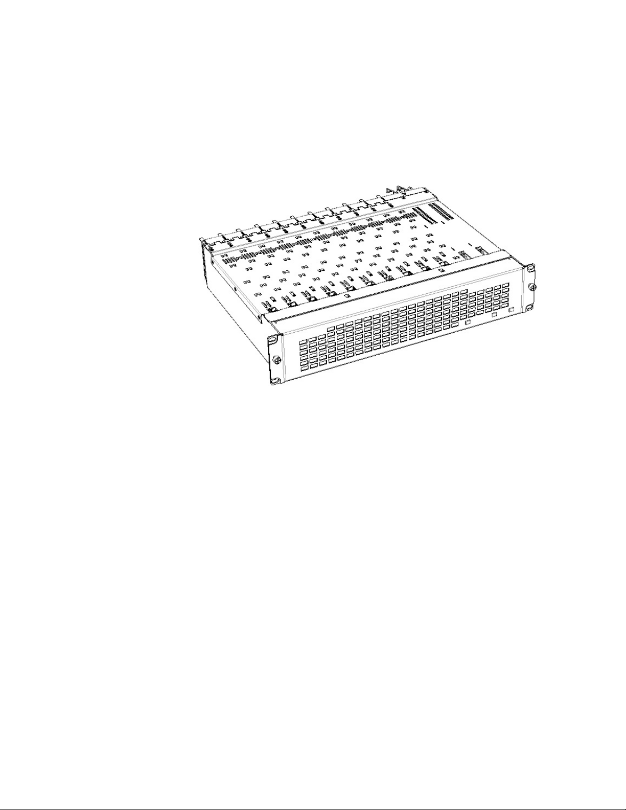
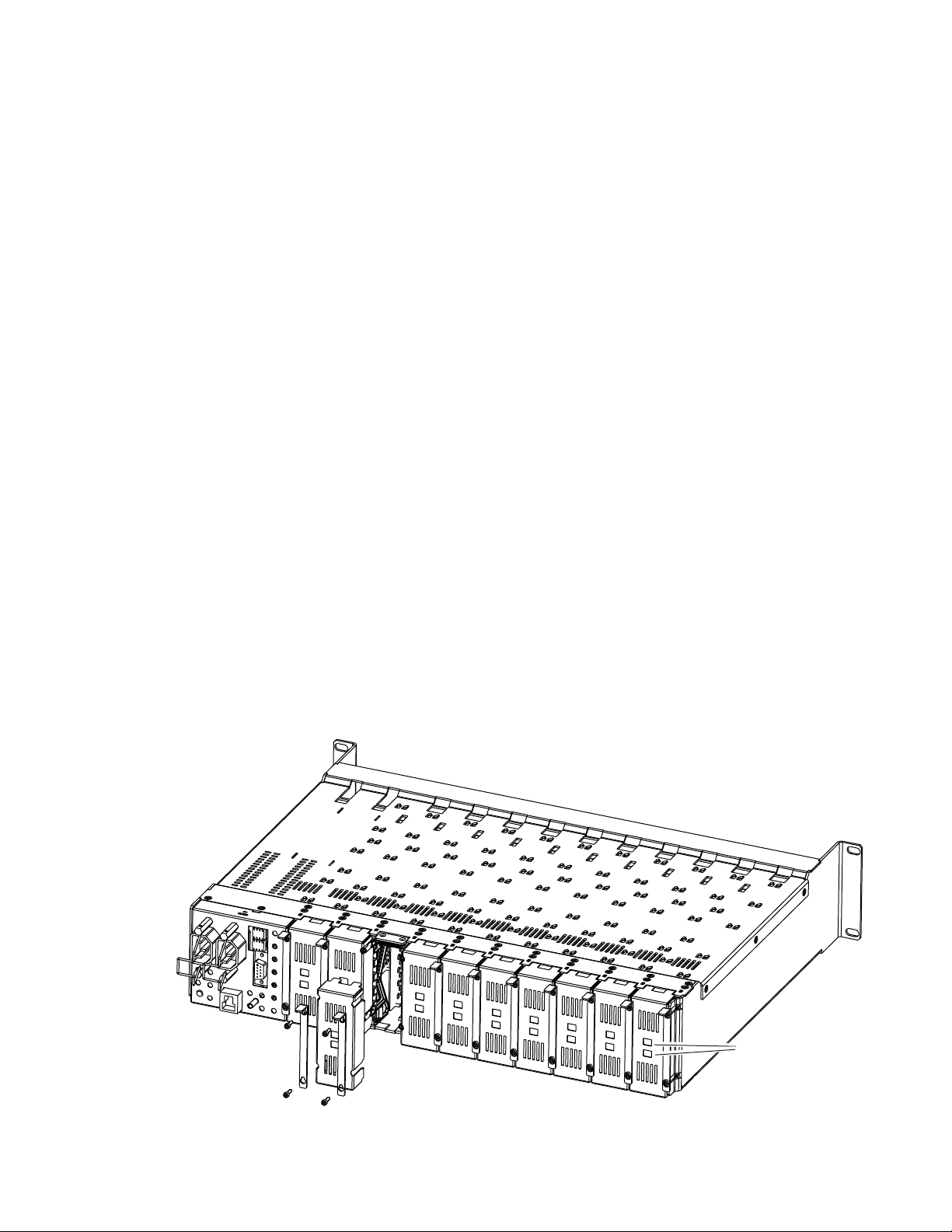
There are ten front and rear cell locations in the 2 RU Gecko Flex frame
Figure 1) to accommodate either audio or analog and digital video module
(
sets. The 8985 module set uses the 8900GFR-R rear module that can be
installed in any one of the ten rear locations.
Figure 1. GeckoFlex Frame
Installation
8985FSP/FS — Instruction Manual 13
Page 14

Installation
Module Installation Precautions
Please read and follow the precautions listed below before installing the
front and rear modules and any fiber optic option submodules:
• Use standard anti-static procedures during installation. As modules
can be installed or removed when the GeckoFlex frame is powered up,
before removing the cover, please use an anti-static bracelet tied to a
metal part of the frame.
• Install the rear module first, the 8900GEN-SM submodule on the front
module (if used), the front module, then the optical submodule option
(if used).
• When installing or removing a rear module, loosen or tighten the
screws holding the retainer clips to the frame manually with the
retainer clip tool provided inside the front cover of the frame or use a
2 mm (5/64”) hex screwdriver. Please do not use an electric screwdriver.
Note On newer 751- version GeckoFlex frames, a Rear Retainer Clip removal tool
and 2 extra retainer clips and screws for installing them are provided on the
inside of the frame cover.
• Make every effort to leave the screws holding the retainer clips in place
(do not remove them completely). They are very small and can easily
drop into other equipment causing a shorting hazard. (Two turns of the
screw should be enough to loosen the screws, 3 turns or more will
remove it.)
• When installing a rear module, tighten the screws on the retainer clips
just until snug. Do not apply more force than is necessary to seat the
rear module. The retainer clip screw torque specification is given in the
Mechanical specifications in Table 5 on page 67.
• If using a fiber optic submodule, handle it carefully, use anti-static precautions, and read the Fiber Optic Cleaning Requirement on page 19 before
cabling.
14 8985FSP/FS — Instruction Manual
Page 15
Rear Module Installation
8444_23r0
Use retainer clip or
needlenose pliers
to pull out blank after
removing retainer clips
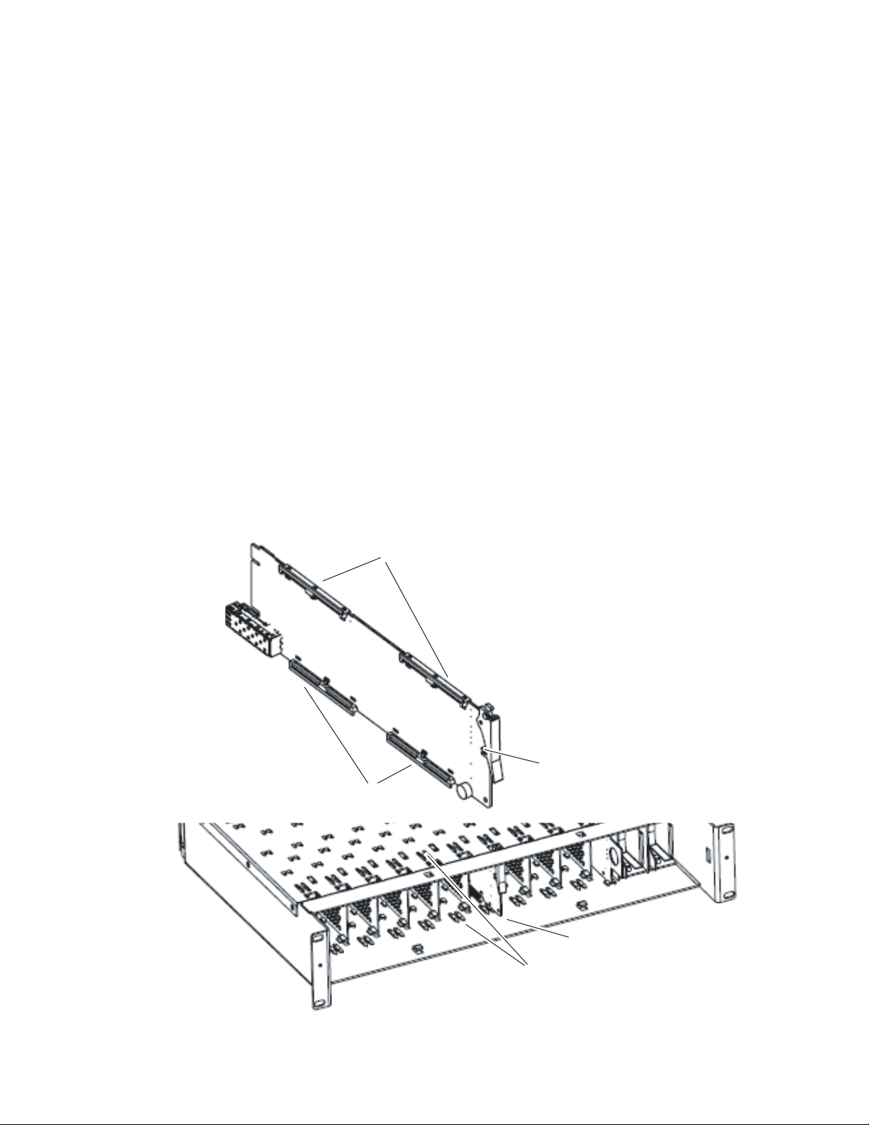
To install the rear module, refer to Figure 2 and the instructions below:
1. To remove a blank rear adapter cover (or a rear module already
present), manually loosen the two screws holding each retainer clip on
the rear adapter cover or rear module to the frame with the retainer clip
tool provided inside the front cover of the frame (newer model frames
only) or a 2 mm (5/64”) hex screwdriver. Do not remove the screws.
Note To remove a rear module already installed, follow the same steps. It is helpful
to first remove the front module so the rear can be pulled out more easily.
2. After loosening the retainer clip screws, pull up on each retainer and
completely remove it, leaving the screws in place.
3. Remove the blank rear adapter cover by inserting needlenose pliers
into the slots in the blank cover and pulling it off.
4. Insert the rear module into the empty slot, guiding it carefully.
5. Replace each retainer clip over the two screws on both sides of the
module and push down to seat the retainer clip.
Installation
6. Tighten the two screws on each retainer clip just until they come into
contract with the retainer clip then tighten about a 1/4 turn more. The
retainer clips should not bend or be bowed. The rear retainer clip screw
torque specification is 4-5 inch-lb/0.45-0.6Nm).
Note All unused rear slots in a GeckoFlex frame should have a blank rear adapter
cover installed.
Figure 2. Installing Rear Module (751- Version Frame Shown)
8985FSP/FS — Instruction Manual 15
Page 16
Installation
8431_05
Install Genlock submodule
on back of circuit board.
Center submodule connector J1
over front module connector J14
and snap in place. From top side
of module, tighten the screw provided
to the standoff on the circuit board.
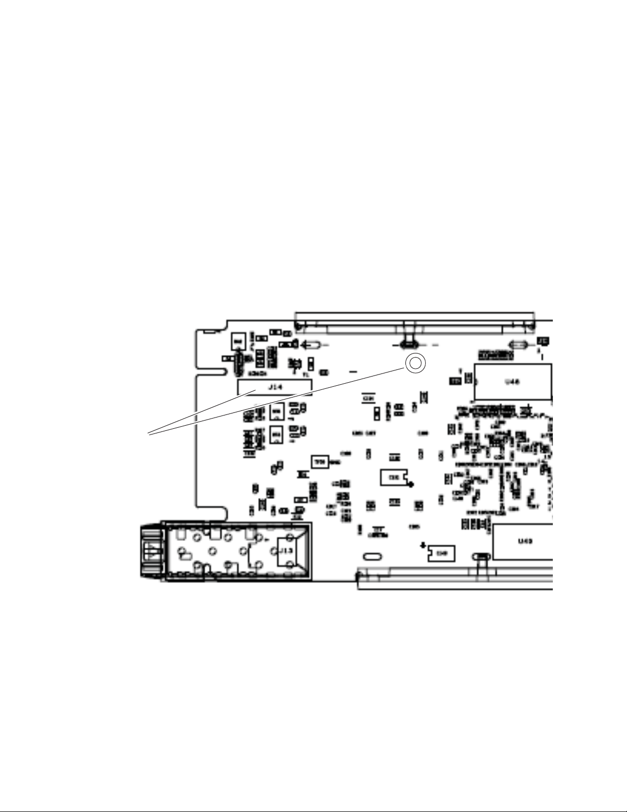
Genlock Submodule Installation
The Genlock submodule will ship in a separate package and must be
installed on the front module.
To install a Genlock submodule, follow these steps:
1. Locate the Genlock connector J14, on the back side of the 8985FSP or FS
circuit board (Figure 3).
2. Line up the connector on the submodule, J1, with J14 on the front
module and snap the submodule into place making sure the holes in
each circuit board line up.
3. To hold the submodule in place, attach the screw provided from the
bottom of the front module to the standoff on the submodule circuit
board.
Figure 3. Installing Genlock Submodule
16 8985FSP/FS — Instruction Manual
Page 17
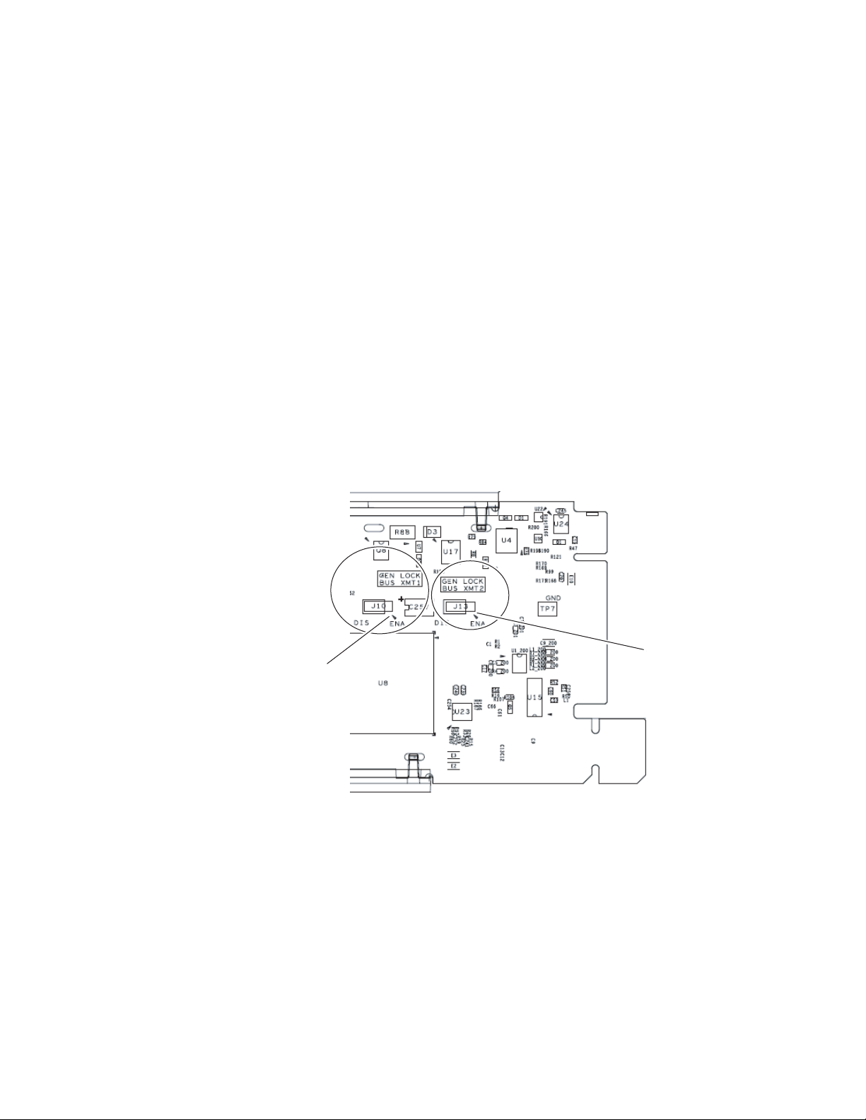
Frame Bus Jumpering
If you will be using this 8985 module to distribute reference Frame Bus 1
(slot 1) or Frame Bus 2 (slot 3), you must set a jumper on the front module
circuit board for this purpose before installing the module (
• Frame Bus 1 – to transmit the reference connected to one of the Genlock
Loop BNCs on the corresponding rear module on Frame Bus 1, set
jumper J10 to
the frame and configured on the Genlock web page (see Genlock Web
Page on page 59) for
• Frame Bus 2 – to transmit the reference connected to one of the Genlock
Loop BNCs on the corresponding rear module on Frame Bus 2, set
jumper J13 to
the frame and configured on the Genlock web page (see Genlock Web
Page on page 59) for
Note Both jumpers may be enabled. The module in slot 1 will only read the status
of jumper, J10. The module in slot 3 will only read the status of jumper, J13.
Installation
Figure 4).
ENA (pins 1-2). This module must be installed in slot 1 of
Auto in the Drive Frame Reference Bus pulldown.
ENA (pins 1-2). This module must be installed in slot 3 of
Auto in the Drive Frame Reference Bus pulldown.
Figure 4. Setting Frame Bus Jumpers
For Frame Bus 1 distribution, set
GEN LOCK BUS XMT1 jumper, J10
Pins 1-2 (ENA) or pins 2-3 (DIS).
Pin 1 of J10
For Frame Bus 2 distribution, set
GEN LOCK BUS XMT2 jumper, J13
Pins 1-2 (ENA) or pins 2-3 (DIS).
Pin 1 of J13
8431_06
8985FSP/FS — Instruction Manual 17
Page 18
Installation
8431_07
Slide top and bottom card carriers on module
over top and bottom guides on right of slot.
Module installed
Locking Pin
Card Carriers
Card Carriers
Front Module Side View
Front Module Installation
After installing the rear module and the Genlock submodule if required,
and setting the Frame bus jumpering if required, install the front module as
follows:
1. Remove the front cover of the frame if required.
2. Locate the corresponding front slot.
3. Set the on-board jumper Local/Remote jumper, J5 on the module circuit
board, for local and remote operation (LOC/REM position, pins 2-3) or
to lock out remote control (LOCAL position, pins 1-2).
4. Insert the front module so that the plastic card guides on the module
top and bottom edges go over the upper and lower raised rail guides on
the right of the top and bottom of the slot (Figure 5).
5. Carefully slide the module into the rear connector.
6. Lock the front module ejector tab into the locking pin.
Note Before removing the front module, first remove the Fiber Optic submodule if
present, from the rear module.
Figure 5. Front Module Installation
18 8985FSP/FS — Instruction Manual
Page 19

Optional Fiber Optic Submodule Installation
After the front and rear modules have been installed, install the SFP Fiber
Optic submodule option if being used into the rear module metal cage
labeled FIBER (
and may be installed or removed with power applied to the module.
CAUTION Use anti-static precautions and handle the submodule carefully when
installing and the removing it.
to clean all fiber connections as described in Fiber Optic Cleaning Require-
ment below.
Refer to Tab le 1 for the correct model of submodule to use with different
software versions.
Table 1. Fiber Optic Submodule Summary
Submodule Type SW 1.3.2 and later SW 1.3.2 and earlier
SFP-13103G-M1DRX Dual Receiver X –
SFP-13103G-M1DTX Dual Transmitter X –
SFP-13103G-M1TRX Transceiver X –
1310nm-DRL Dual Receiver X X
1310nm-DTL Dual Transmitter X X
1310nm-TRL Transceiver X X
Figure 6 on page 20). The SFP submodule is hot-pluggable
Before inserting the fiber cable, it is important
Installation
Fiber Optic Cleaning Requirement
Before making any fiber optic cable mating connections, including installation, and after every de-mating cycle, use an industry standard fiber optic
cleaning kit, including oil-free compressed air, to clean the fiber connectors
and the connectorized fiber end faces. This helps ensure optimum perfor
mance of the fiber optic interface. Industry standard fiber optic cleaning
kits can be purchased on the web and in electronics stores.
-
8985FSP/FS — Instruction Manual 19
Page 20
Installation
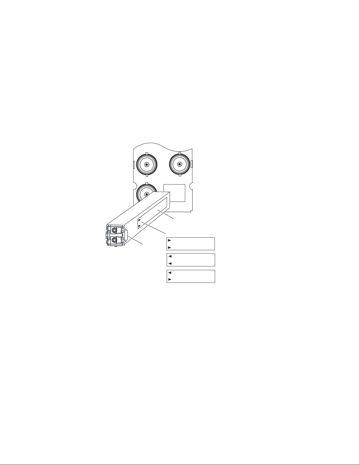
FIBER
J7J9J8
8431_03r1
Label
Handle
Arrow Indicators:
SFP-13103G-M1DRX
SFP-13103G-M1DTX
SFP-13103G-M1TRX
To install the fiber optic submodule:
1. Slide the fiber optic device into the metal fiber cage with the label and
handle to the right.
2. Push the device in as far as it will go without forcing it. It will not go
completely into the cage.
3. Cable the fiber optic connectors according to the instructions given in
Video Inputs on page 22 and Video Outputs on page 22.
Note Fiber inputs or outputs must be enabled in configuration.
Figure 6. Installing Fiber Optics Submodule
Removing an SFP Submodule
If you need to remove an SFP submodule, snap the handle out and pull the
submodule slowly out of the metal cage.
20 8985FSP/FS — Instruction Manual
Page 21
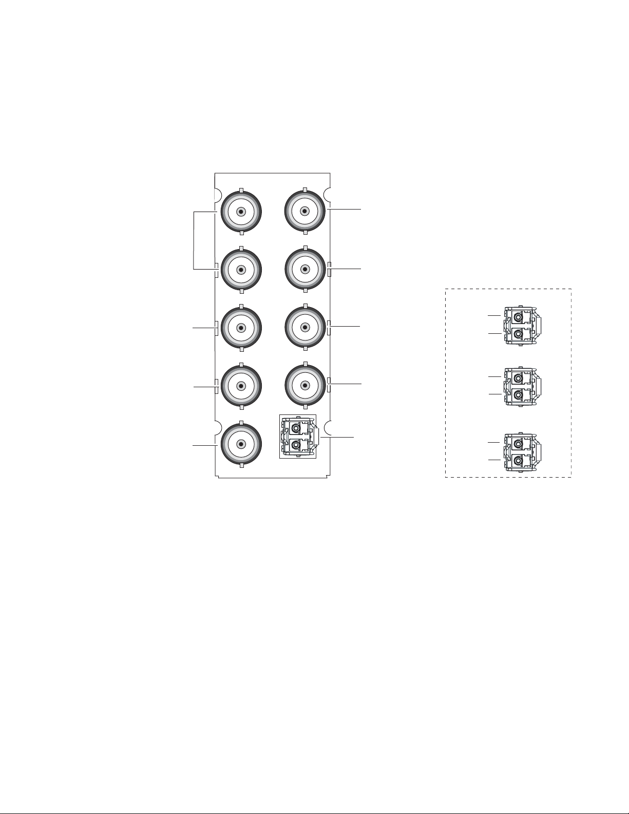
Cabling
8431_02r2
8900GFR-R
FIBER
J1 J2
J3 J4
J5 J6
J7J9J8
J1 and J3:
Genlock Loop
J9: Coax In
J5: SDI Out
J7: SDI Out
J8: SDI Out
Fiber Inputs/Outputs
(See Fiber Optic Cabling
at right.)
J6: SDI Out
J2: Auto Tracking
Delay Output
J4: Auto Tracking
Delay Output
Fiber Optic Cabling
Fiber Rx 1
Fiber Tx 2
Fiber Rx 2
SFP-13103G-M1DRX
SFP-13103G-M1DTX
SFP-13103G-M1TRX
Fiber Tx 1
Fiber Rx 1
Fiber Tx 2
Installation
Cabling is done on the rear BNCs of the 8900GFR-R module illustrated in
Figure 7. Inputs and outputs are also illustrated on the I/0 Config web page
(I/O Config Web Page on page 39).
Figure 7. 8900GFR-R Rear Module
8985FSP/FS — Instruction Manual 21
Page 22

Installation
Video Inputs
Connect an HD or SD digital video signal to the Coax input at BNC J9,
and/or to one or both of the fiber inputs at fiber connector J10 (depending
on the type of fiber submodule installed).
Note Refer to Table 3 on page 45 for important video input and external genlock
reference input video frame rate compatibility information.
For fiber optic inputs, a Dual Receiver (RX1 and RX2) or Transceiver (RX1)
SFP optical submodule must be installed. Fiber inputs must be enabled
with remote controls. Only one video input can be used at a time and must
also be selected with remote controls.
Video Outputs
There are four electrical coax video outputs at BNCs J5, J6, J7, and J8.
If a Transceiver SFP optical submodule is installed, one fiber optic output
(TX2) is also available. If a Dual Transmitter SFP optical submodule is
installed, two fiber optic outputs (TX1 and TX2) are also available. Each
fiber optic output must be enabled using local or remote controls. All coax
and fiber optic outputs can be active at the same time.
Genlock Loop
BNCs J1 and J3 are looping inputs to support the optional Genlock submodule on the 8985FSP/FS module with an external genlock reference
(NTSC/PAL color black or Tri-level sync). Refer to
table of compatible frame rates for installing the external genlock reference.
Connect an external reference to J1 or J2 and loop the other input to another
device or terminate the unused input.
Auto Tracking Delay Outputs
BNCs J1 and J3 output an auto tracking delay signal that can be fed to audio
modules to synchronize the audio to the Genlock reference from the
8985FSP/FS module.
Ta bl e 4 on page 61 for a
22 8985FSP/FS — Instruction Manual
Page 23
Power Up
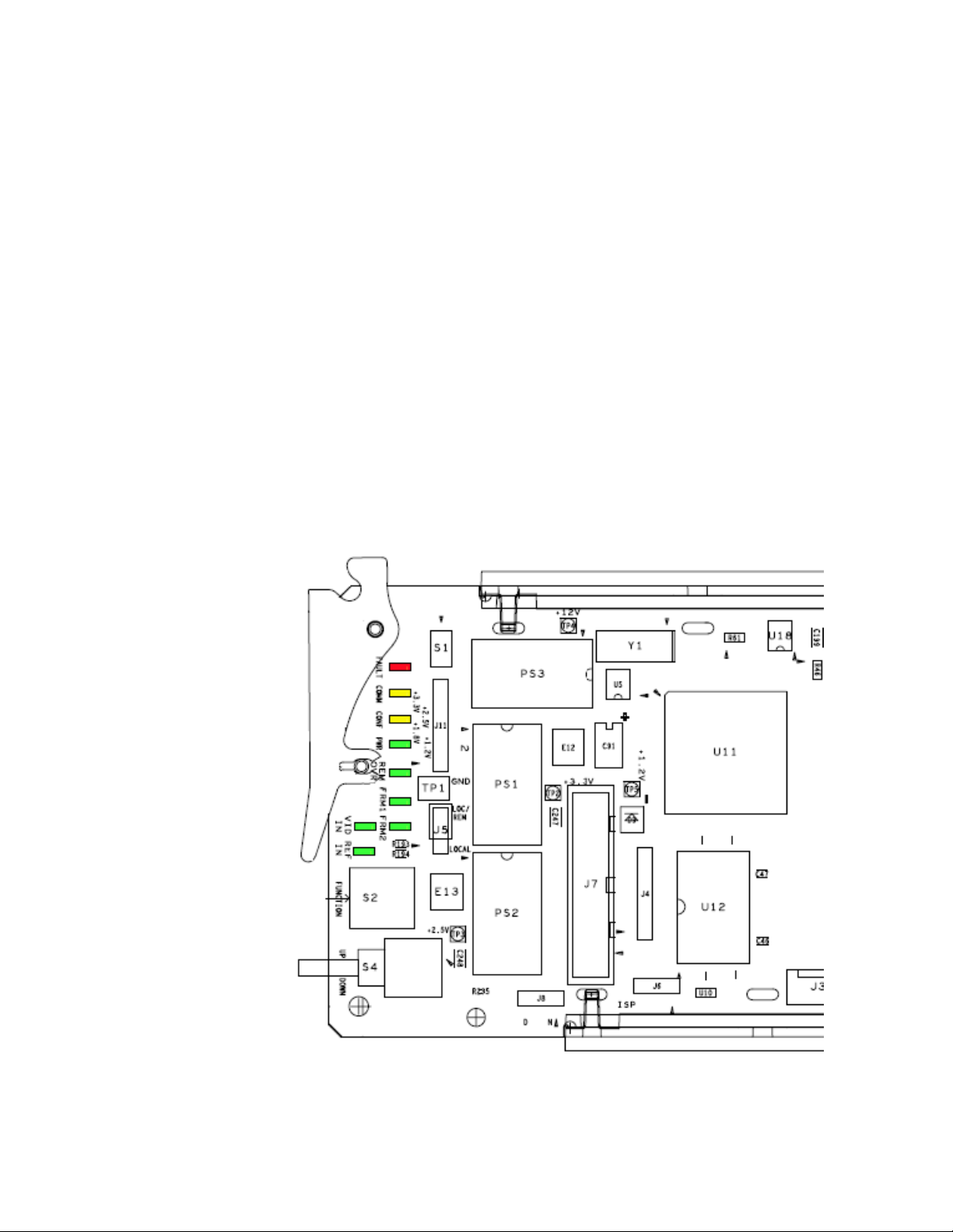
Operation Indicator LEDs
Power Up
The front LED indicators and configuration switches are illustrated in
Figure 8. Upon power-up, the green PWR LED should light and the yellow
CONF LED should illuminate for a few seconds for the duration of module
initialization. The on-board configuration switches are not used on these
modules.
Note When a media module is first plugged into a GeckoFlex frame, the 8900NET
module (if present) may report a momentary fault. This will clear once the
media module has booted up.
With factory default configuration and a valid input signal connected, the
green PWR and (
illuminate (refer to Tabl e 2 on page 24 to see the possible operating indicator combinations).
Figure 8) on the top side of the module front edge should
Figure 8. Front Panel LED Indicators
8985FSP/FS — Instruction Manual 23
Page 24

Power Up
Table 2. Board Front Edge LED Names and Meaning
LED Indication Condition
FAULT
(red)
COMM
(yellow)
CONF
(yellow)
PWR
(green)
REM OVR
(green)
FRM1
(green)
FRM2
(green)
VID IN
(green)
REF IN
(green)
Off Normal operation.
On continuously Module has detected an internal fault.
Flashing Indicates a warning condition such as configuration problems or missing video. Check inputs and configuration settings.
Off No activity on frame communication bus.
3 Quick Pulses Locate Module command received by the module from a remote control system.
Short flash Activity present on the frame communication bus.
Off Module is in normal operating mode.
On continuously Module is initializing, changing operating modes or programming hardware.
3 Quick Pulses Locate Module command received by the module from a remote control system.
Off No power to module or module’s DC/DC converter failed.
On continuously Normal operation, module is powered.
Off
On
Off Reference frame bus is disabled to frame on Genlock web page or no Genlock submodule is installed in slot 1.
On Reference frame bus is enabled on Genlock web page and Genlock submodule is installed in slot 1.
Off Reference frame bus is disabled to frame on Genlock web page or no Genlock submodule is installed in slot 3.
On Reference frame bus is enabled on Genlock web page and Genlock submodule is installed in slot 3.
Off Indicates no valid input signal is being detected.
On Indicates a valid input signal is being detected.
On Indicates no valid reference signal is being detected or signal is not locked.
Off Indicates a valid reference signal is present and locked.
Not used on these modules, no local configuration controls.
24 8985FSP/FS — Instruction Manual
Page 25

Configuration
Configuration
The 8985FSP/FS module can only be configured remotely using the
8900NET network interface GUI or a networked Newton control panel. An
8900NET (Net Card) module running software version 4.3.0 or later is rec
ommended for optimum operation and required for software updating.
(See
Software Requirements on page 11 for instructions for upgrading this
software.)
Refer to the following sections for configuration instructions:
• Configuration Overview (page 25)
• Remote Control and Monitoring (page 28)
• Configuration Parameter Summary (page 75)
Operation of these control types is explained in detail in their respective
sections of this manual.
-
Configuration Overview
This section provides a brief overview of all parameters that can be configured on the 8985 module. Use this section in conjunction with the specific
configuration method instructions for each configuration type.
page 75 provides a summary in table format of all parameters and their
ranges, default values, and remote web page and Newton control panel
function names and locations for setting each value.
Video Input Selection
Set the type of input connection from a coaxial electrical input or, if an
optional SFP Fiber Optic submodule is installed, one of the fiber optic
inputs.
System Configuration
System configuration is required for selection of the video input standard,
enabling of the colorbars test signal, selection of the output timing source
when the Frame Sync option is enabled, and the Reference Restore param
eters can be set. A Split Screen mode for comparing the input to the output
can also be enabled on the System Config web page.
Ta bl e 9 on
-
8000GEN-SM Reference Timing
When an 8900GEN-SM submodule is installed as either a local reference to
the host module or configured to output frame buses from host modules in
slot 1 and slot 3, the genlock timing can be adjusted to match reference
timing.
8985FSP/FS — Instruction Manual 25
Page 26

Configuration
Split Screen Control
A Split Screen function can be enabled for comparing the unprocessed
input to the processed output. This function is very useful when using the
color correction or video processor controls. The Split Screen orientation
can be set vertically or horizontally and can be adjusted for the amount of
video to be displayed (10-90%). Interactive Split Screen controls are present
on the 8995FSP System Config, Video Processing, and Color Correction
web pages.
Video Timing and Loss of Signal Controls
On a 8985FSP/FS module with Frame Sync, the following timing adjustments are available:
• Horizontal Timing – adjusts the horizontal delay of the channel output
in pixels
• Vertical Timing – adjusts vertical delay in line increments
Also available on the 8985FSP with Frame Sync are the following controls
for setting the output condition when there is a loss of input signal:
• Auto Blue – when Auto Blue is enabled on a channel, the output will
automatically freeze to a blue screen when the input signal is lost on the
input.
• Auto Freeze – when Auto Freeze is enabled on a channel, the output
will automatically freeze on the last valid field when the input signal is
lost on the input.
• A Manual freeze can be performed at any time with the following two
choices:
•Frame
• Field
Note A field freeze provides less resolution and no motion artifacts in the output.
In frame mode, the resolution is higher since both fields are present, but the
presentation of the two fields can cause motion artifacts.
• Multi-frame Delay – up to 6 frames of delay can be added to the signal
as needed. When the H and V Timing controls are set to maximum, the
total delay of the module can be 8 frames (when
selected)
• Minimum Delay Mode – the module can be set for minimum delay
mode that bypasses portions of the frame sync memory to allow an
absolute minimum amount of delay through the module. This mode is
for special cases where the input is synchronous and its position with
respect to the reference is well known.
Minimum Delay is not
26 8985FSP/FS — Instruction Manual
Page 27

Color Correction
On the 8985FSP module, color correction controls are provided for making
RGB gain, offset and gamma correction adjustments. Each color channel
can be adjusted separately or a total gain or total gamma can be applied to
all channels.
Gamma controls brighten and darken the gray intensity of the signal.
Raising the gamma above 1.0, brightens the gray intensity. Lowering the
gamma below 1.0, darkens the gray intensity.
Video Processing Adjustments
On the 8985FSP module, component level (Y, Cr, Cb) adjustments are provided in the Video processor for video gain and offset, chroma gain, phase
control (hue), and color saturation. Each color component can be adjusted
separately or the total gain can be adjusted.
Y/C clipping controls are available in the Video Proc for adjusting the top
(white) and bottom (black) luminance levels and the white clipping on
chrominance channel of the output signal (C White Clip).
Configuration
User Settings
Module default parameters and default signal names can be recalled at any
time for the entire module or subsets of parameters such as the color cor
rector or video processor.
On the web pages, a Defaults button at the bottom of each applicable web
page is available to return the parameters on that page to the factory
defaults.
Save and load module configuration to/from a file are also provided on the
web pages.
Video Outputs
When there is a Dual Transmitter (2 outputs) or Transceiver (1 output) fiber
optic submodule installed, one or both fiber outputs must be enabled for
operation.
-
8985FSP/FS — Instruction Manual 27
Page 28

Configuration
Remote Configuration and Monitoring
8985FSP and FS module configuration and monitoring must be performed
using a web browser GUI interface or a networked Newton Control Panel
when the 8900NET Network Interface module is present in the GeckoFlex
frame. Each of these interfaces is described below.
Note The local configuration switches are present but not active on this module.
8900NET Module Information
Refer to the 8900NET Network Interface Module Instruction Manual for information on the 8900NET Network Interface module and setting up and
operating the GeckoFlex frame network.
Note The 8900NET module in the GeckoFlex frame must be running software
version 4.3.0 or higher for proper remote control panel operation and software updating. Upgrade software and instructions for the 8900NET can be
downloaded from the Grass Valley ftp site.
Newton Control Panel Configuration
A Newton Control Panel (hard and/or soft version) can be interfaced to the
GeckoFlex frame over the local network. Refer to the documentation that
accompanies the Newton Modular Control System for installation, config
uration, and operation information.
Control panel access offers the following considerations for module configuration and monitoring:
• Ability to separate system level tasks from operation ones, minimizing
the potential for on-air mistakes.
• Ability to group modular products—regardless of their physical locations—into logical groups (channels) that you can easily manipulate
with user-configured knobs.
• Update software for applicable modules and assign frame and panel IP
addresses with the NetConfig Networking application.
• Recommended for real-time control of module configuration parameters, providing the fastest response time.
Note Not all module functions are available with the control panel, such as E-MEM
and factory default recalls. The available control panel controls for the 8985
module are listed in Table 9 on page 75.
-
An example of the Newton Configurator is shown in Figure 9 on page 29.
28 8985FSP/FS — Instruction Manual
Page 29

Figure 9. Newton Configurator Example
Configuration
Web Browser Interface
The web browser interface provides a graphical representation of module
configuration and monitoring.
Use of the web interface offers the following considerations:
• Provides complete access to all module status and configuration func-
tions, including naming of inputs and outputs, factory parameter and
name default recalls, E-MEM functions, slot configuration, and SNMP
monitoring controls.
• Web access will require some normal network time delays for pro-
cessing of information.
• Configuration parameter changes may require pressing
Enter, upload processing time, and a manual screen refresh to update the
web page.
• Web interface recommended for setting up module signal and slot
names, E-MEMS, and reporting status for SNMP and monitoring.
Apply button or
8985FSP/FS — Instruction Manual 29
Page 30

Configuration
8431_08r3
The Links section lists the frame and its current modules. The selected link's Status
page is first displayed and the sub-list of links for the selection is opened. The sub-list
allows you to select a particular information page for the selected device.
Content display section
displays the information page
for the selected frame or module (frame slot icons are also
active links).
Refresh button for manual
update of page
Refer to the Frame Status page shown in Figure 10. The modules can be
addressed by clicking either on a specific module icon in the frame status
display or on a module name or slot number in the link list on the left.
Note The physical appearance of the menu displays on the web pages shown in
this manual represent the use of a particular platform, browser and version
of 8900NET module software. They are provided for reference only. Displays
will differ depending on the type of platform and browser you are using and
the version of the 8900NET software installed in your system. This manual
reflects Windows XP and an 8900NET module with software version 4.3.0.
For information on status and fault monitoring and reporting shown on the
Status page, refer to
Figure 10. GeckoFlex Frame Status Page
Status Monitoring Summary on page 70.
30 8985FSP/FS — Instruction Manual
Page 31

Configuration
Web Page Operations and Functional Elements
The following conventions and functional elements (shown at left) are used
in GeckoFlex web page operations. (The examples shown throughout this
manual represent 8900NET software version 4.3.0):
Pulldown Menus
Button
Radio button
Check box
Refresh button
Coarse Adjust
Fine Adjust
Enter
Low Limit
Status Indicator
Entry Field
High Limit
• Pulldown menus allow you to choose selections from a list.
• Clicking on a button performs an immediate action such as recall of
defaults, clearing of states, learning configurations, and selecting all or
none of a selection.
• Radio buttons are used to make a choice of one parameter in a group.
• Check boxes are used when a selection can be enabled or included in a
group. Multiple check box selections or enables can be made for some
parameters.
Refresh button (circular arrow) is provided at the top of each web page
•A
for manual refresh to view recently changed parameters.
• Each numerical adjustment control has a
Coarse adjust button (left and
right top double arrows) which increases or decreases the step value by
a factor of 10. The
Fine adjust button (left and right inside single arrows)
increases or decreases the step value by 1.
To change a value, use the arrow button controls or enter a value into
the number field and select the
Enter button (*) or use the Enter key on
your keyboard. The Status Indicator bar will follow the value selected.
Use the Low and High Limit buttons to go directly to the lowest and
highest limits for the parameter.
Status LED
• An entry field allows naming of various module functions such as
8341_13
input or output signals, asset tag, and slot identification.
•The
Status LED icon indicates module status and is a link to the module
Status web page.
LED colors indicate:
• Green = Pass – no problems detected
• Yellow = Configuration error warning
• Red = Fault condition detected
8985FSP/FS — Instruction Manual 31
Page 32
Configuration
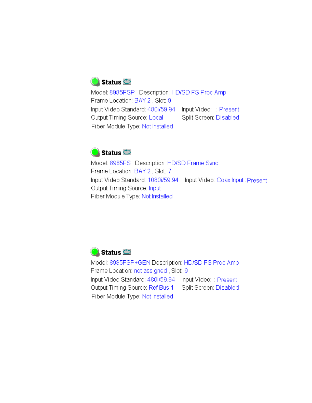
Web Page Headers
Each configuration web page has a Status and Identification Header as
shown in
Figure 11. 8985FSP Status/ID Header
Figure 12. 8985FS Status /ID Header
Figure 11 for the 8985FSP and Figure 12 for the 8985FS module.
When the 8985FSP or FS module has an 8900GEN Genlock submodule
installed, the header shows the addition of the Genlock with + GEN
(
Figure 13).
Figure 13. 8995UDX + GEN Status Web Page
32 8985FSP/FS — Instruction Manual
Page 33

Configuration
The header information on each web page includes the following:
• Model and Description are read-only generated by the module.
Frame Location is defined on the 8900 Series GeckoFlex Frame Configura-
•
tion web page.
Slot number reports the module’s location in the frame.
•
Input Video Standard reports the input video type and rate selected on the
•
System Config web page.
•
Input Video reports the status of the video input to the module.
Output Timing Source reports the output timing source (Frame Reference
•
or Input) chosen on the System Config web page.
Split Screen interactive status is reported (Enabled or Disabled) as set on the
•
System Config, Color Correction, or Video Proc Amp web pages on the
8985FSP module. Not present on the 8985FS module.
•
Fiber Module Type is reported in the Status, Video Input, and Video
Output web page headers only.
Web pages with configuration parameters each have a
bottom of the page to allow resetting of
page. Default values for all parameters are listed in Tab le 9 on page 75.
default parameters for only that
Defaults button at the
Web Page Links
The web interface GUI provides the following links and web pages for the
8985FSP and FS modules (Figure 14 on page 34):
• Status – reports input and output sign
tion status, module status and information, warnings and errors
(page 35),
• I/O Config – shows a graphic representation of inputs and outputs to
the module and allows naming of each input and enabling and disabling of signal reporting (page 39),
• Video Input – allows selection of the video input source and provides
the status of all sources, including fiber optic submodule option inputs
(page 41),
• System Config – select input video line standard, enable color bars test
signal, set output timing source, set Reference Restore parameters, view
phase difference graph, and controls for Split Screen functions
(page 42),
al status, frame bus communica-
• Frame Sync – provides horizontal and vertical timing, loss of signal
controls, Minimum and Multi-Frame delay controls, and a Timing
Status table showing total delay through the module (page 48),
• Color Correction – (8985FSP only) provides RGB gain, offset and
gamma correction adjustments and controls for Split Screen functions
(page 52),
8985FSP/FS — Instruction Manual 33
Page 34

Configuration
• Video Proc – (8985FSP only) provides overall video processing and clip
controls (White and black for luminance channel, white for C channel)
for the HD or SD signal, and controls for Split Screen functions
(page 54),
• User Settings – allows recalling of factory defaults for all module
parameters or factory signal names, and provides a save/load configuration file function (page 56),
• Genlock – appears only on the 8985FSP and FS module links when the
optional 8900GEN-SM submodule is installed on the module. This is
also reflected in the web page header as shown in Figure 14 on page 34.
Provides status reporting for the external genlock reference and controls for enabling the Genlock, matching the reference input to a selection standard, and setting reference signal delay (page 59),
• Video Out – enable and disable the fiber optic outputs when a fiber
module is installed (page 63), and
• Slot Config – provides Locate Module, Slot Identification, and Slot
Memory functions along with links to the 8900NET SNMP, LED
Reporting, and Frame Alarm configuration web pages (page 64).
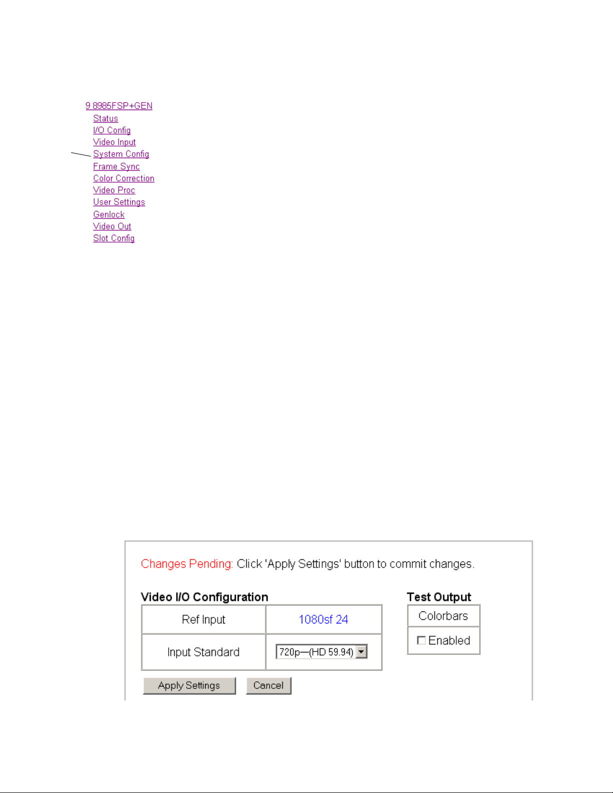
Figure 14. 8985FSP and FS Web Page Links
A summary table of all module parameters including defaults, ranges, and
Newton Control panel controls is given in
Ta bl e 9 on page 75.
34 8985FSP/FS — Instruction Manual
Page 35

Status Web Page
Use
this
link
The Status web page (Figure 15 on page 37 for the 8985FSP module and
Figure 16 on page 38 for the 8985FS module) reports information and status
about the front media and rear modules and any submodules present (if
app
licable for the module) in both graphical (using color to indicate status)
and textual formats. It also reports the status of the input and reference
video signals to the module and submodules, and the Frame Bus status.
Video and reference signal reporting can be enabled and disabled at the
module level on the I/O Config web page (page 39).
Configuration
In general, graphics and text colors us
lowing:
• Green = Pass – signal or reference present, no problems detected.
Red = Fault – fault condition.
•
• Yellow = Warning – signal is absent, has errors, or is mis-configured.
• Gray = Not monitored.
Note Always refresh the page first with the Refresh button at the top of the page
(shown at left) to update the current status of the web page.
ed for status indication are the fol-
Web Page Header
The content of the web page header for the module is described in detail in
Web Page Header on page 35.
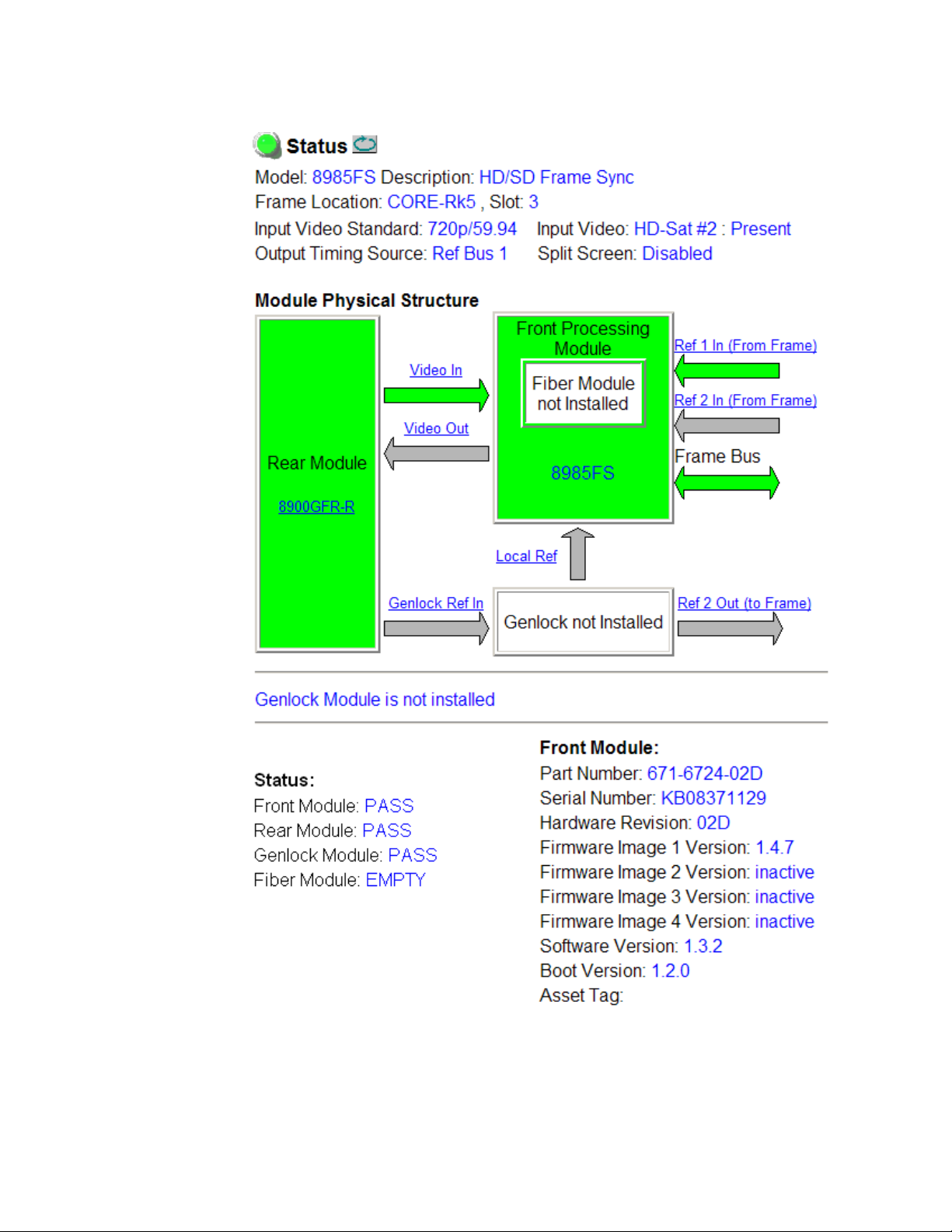
Module Physical Structure
Status is reported for the front, rear, and optional submodules as follows:
• Rear Module – the presence, name, an
module is reported in the graphic on the left. If the rear module is the
wrong type or missing, the graphic will indicate the status by color and
text within the graphic.
d internal status of the rear
• Front Processing Module – the presence, name, and internal status of
the front processing module is reported in the graphic on the right. The
graphic will indicate the status of the front module by color and text
within the graphic.
• Fiber Module – the optional fiber optic submodule status will be shown
in the box on the front module graphic. When a fiber optic submodule
is installed, the type will be reported in the top header and the Status
text below the graphic on the right.
• Genlock Submodule – the status and presence of the optional Genlock
submodule is reported in the front module graphic and the Status text
below the graphic on the right.
8985FSP/FS — Instruction Manual 35
Page 36

Configuration
Status is reported for each of the following video or reference signals:
• Video In – indicates the status of the video input to the module from the
coax BNC, or one of two possible fiber optic inputs (depending on the
type of fiber optic connector installed).
• Video Out – (gray) not monitored in this application.
• Genlock Ref In – indicates the status of the external genlock reference
signal at BNCs J1 and J3 (Genlock Loop).
• Local Ref – indicates the status of the internally generated genlock reference signal from the 8900GEN-SM submodule to the front module.
• Frame Bus – indicates the status of the communication bus between the
8900NET module and the module.
• Ref 1 and Ref 2 In (From Frame) – the Ref 1 arrow will be present when
Frame Bus 1 has been enabled on the module in slot 1. The Ref 2 arrow
will be present when Frame Bus 2 has been enabled on the module in
slot 3 of the frame.
Warning/Fault/Message Reporting
Faults, warnings, and informational messages from the module are displayed between the double bars below the graphic.
Note Many of these warnings are informational only and concern frame rate com-
patiblilty. Pay close attention to the frame rate compatibility explanations and
tables in this manual.
Module Status
Module status for the front and rear modules (and any submodules if applicable) are reported as PASS, WARNING, ERROR, or EMPTY on the right at
the bottom of the display.
Front Module Information
Information about the module, such as part number, serial number, hardware revision and software, firmware, and boot versions, and asset tag
number (assigned on the
left at the bottom of the display.
Slot Config Web Page on page 64) are given on the
36 8985FSP/FS — Instruction Manual
Page 37
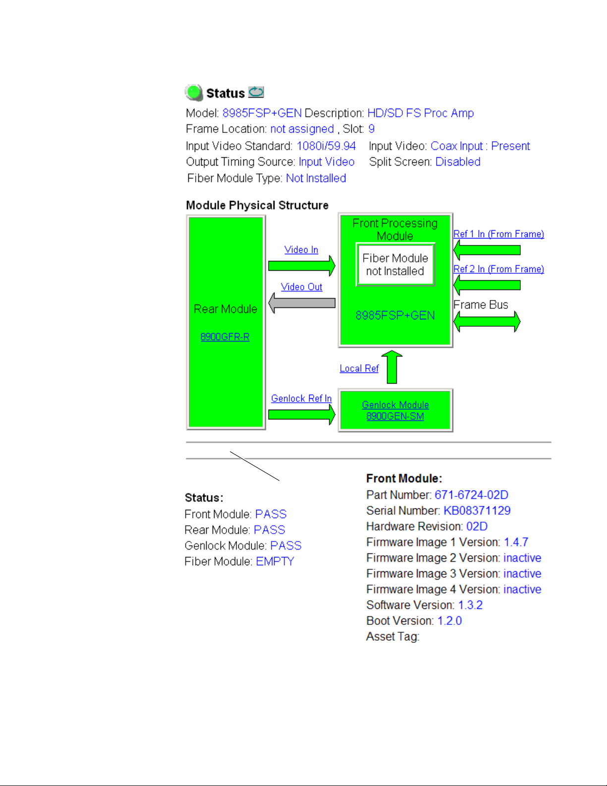
Figure 15. 8985FSP+GEN Status Web Page
Warning messages
Configuration
8985FSP/FS — Instruction Manual 37
Page 38
Configuration
Figure 16. 8985FS Status Web Page
38 8985FSP/FS — Instruction Manual
Page 39

I/O Config Web Page
Use
this
link
Use the I/O Config web page (Figure 17 on page 40) for the following:
Rear Connectors
All of the input and output connectors on the corresponding 8985FSP rear
module are illustrated on the I/O Config web page. The inputs can be configured with the following controls:
Signal Naming – type the desired input name (up to 11 characters) into the
•
corresponding boxes for each input. The status of each input is indicated by the color of the display.
Reporting Enabling – status reporting of each input type can be enabled or
•
disabled by selecting or deselecting the corresponding checkbox in the
Reporting Enabled column for each input type. You may disable reporting
for inputs not being used if desired to avoid error messages. The
Reporting Enabled column is also used when an SNMP monitoring appli-
cation such as NetCentral is installed.
Configuration
Refer to Status Monitoring Summary on pa
color coding and using an SNMP monitoring application.
Note Outputs are not monitored in this application.
ge 70 for a summary of the
8985FSP/FS — Instruction Manual 39
Page 40

Configuration
Figure 17. 8985FSP I/O Config Web Page
40 8985FSP/FS — Instruction Manual
Page 41

Video Input Web Page
Use
this
link
Use the Video Input web page (Figure 18) to select and monitor the video
input source to the module with the following:
Video Input Selection
This section provides the following for the video input signal:
Select Input Video – select the input source from the rear module from one
•
of the following:
•
Coax – corresponds to BNC input J9.
Fiber RX 1 – will be present when either a Dual Receiver or Trans-
•
ceiver SFP fiber optic submodule is installed, or
Fiber RX 2 – will be present when a Dual Receiver submodule is
•
installed.
Signal Name – the signal name defined on the I/O Config web page will
•
appear in each field.
Configuration
•
Signal State – this field reports the status of the selected input video
signal as
Present, Not Present, or Not Supported (no fiber submodule
installed).
Note Only the selected input status is monitored by the module. The input must be
selected to report the correct status. Do not switch inputs without first
selecting the desired input and checking its status.
Figure 18. Video In Web Page
8985FSP/FS — Instruction Manual 41
Page 42
Configuration
Use
this
link
System Config Web Page
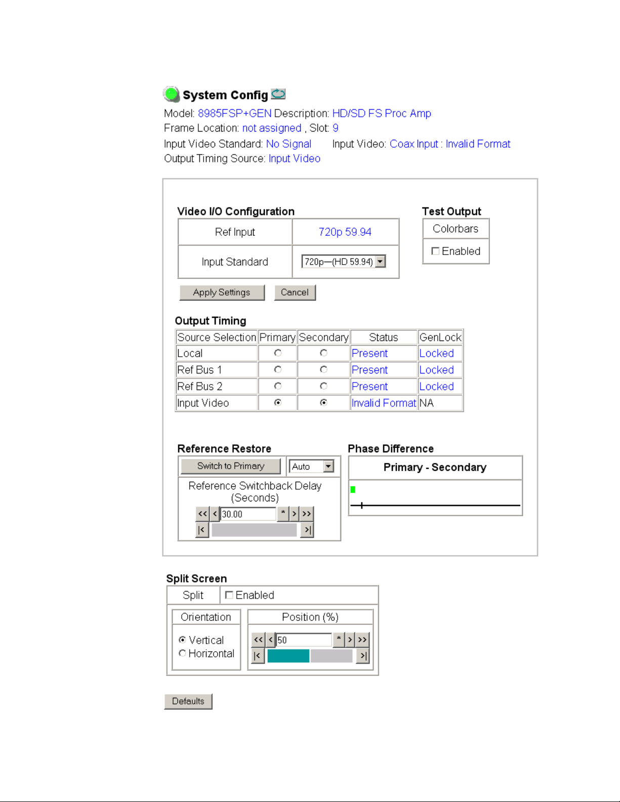
Use the System Config web page (Figure 22 on page 44) to monitor and set
the following system configuration parameters for the module:
Video I/O Configuration
• Ref Input – the reference input standard selected on the Genlock web
page (Genlock Web Page on page 59) is reported in this read-only field.
•
Input Standard – select the video input standard and frame rate selection
from the Input Standard pulldown from the following choices:
• Auto – module will auto-sense input type
• 480i– (SD 59.94)
• 576i–(SD 50)
• 720p–(HD 59.94)
• 1080i–(HD 59.94)
• 720p–(HD 50)
• 1080i–(HD 50)
• 1080p–(HD 24)
• 1080sf–(HD 24)
Note The input video standard must be set to the same frame rate (or compatible
frame rate as listed in Table 3 on page 45) as the reference input when the
input video is associated with the reference input in the Output Timing controls for proper genlocking.
When a new selection is made in the Inputs Standards pulldown, a Changes
Pending message will appear (Figure 19). Click the
make the change.
Figure 19. Changes Pending Message
Apply Settings button to
42 8985FSP/FS — Instruction Manual
Page 43
Configuration
Refresh button
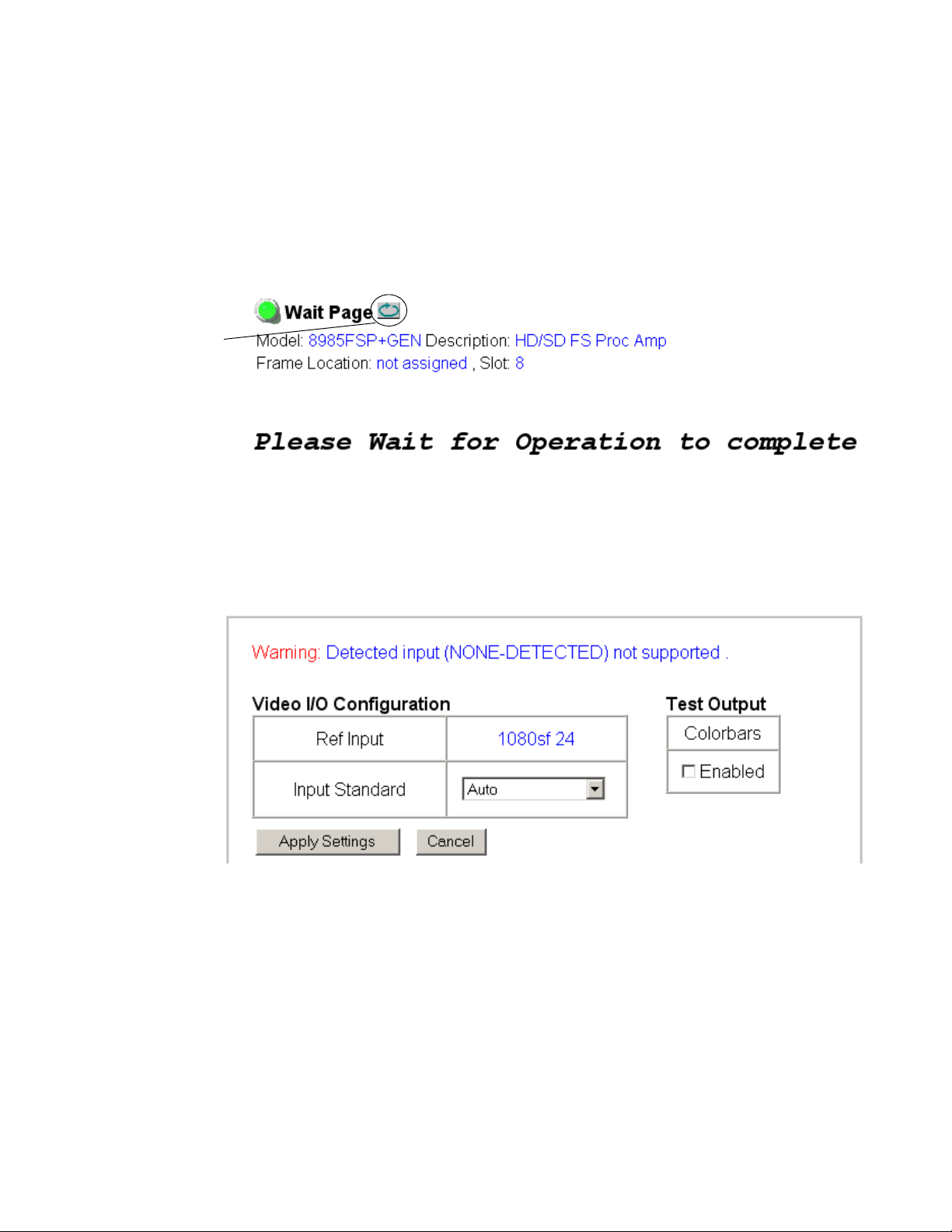
While the module is re-initializing, a Waiting Page (Figure 20) will appear
indicating the module is reconfiguring the input standard. Wait for the
operation to complete. Press the
update the page.
Note Pressing the Defaults button or changing the input type with an E-MEM recall
may also cause the module to re-initialize.
Figure 20. Waiting Message
If the input standard selected is not present or not valid or not supported,
a warning message will report the problem on the System Config web page
as shown in
Figure 21.
Refresh button at the top of the page to
Figure 21. Input Standard Warning Message
8985FSP/FS — Instruction Manual 43
Page 44
Configuration
Figure 22. System Config Web Page
44 8985FSP/FS — Instruction Manual
Page 45

Configuration
Ta bl e 3 is a video input standard to frame reference compatibility table to
indicate what mismatch warnings will occur when the video input standard selected and the reference input are in a mismatch state.
Table 3. Input Video and Frame Reference Compatibility
Video Input Standard
480i
576i
1080i 59.94
720p 59.94
1080i 50
720p 50
1080p 24
1080sf 24
1
A warning will be generated on both the Status and Genlock web pages when this condition
occurs.
Reference
Detected
NTSC None
1080i 59.94 TLS None
720p 59.94 Yes
PAL None
1080i 50 TLS None
720p 50 TLS Yes
1080i 59.94 TLS None
NTSC None
720p 59.94 TLS Yes
720p 59.94 TLS None
NTSC None
1080i 59.94 TLS Yes
1080i 50 TLS None
PAL None
720p 50 TLS Yes
720p 50 TLS None
PAL None
1080i 50 TLS Yes
1080ip 24 TLS None
1080sf 24 TLS None
PAL Yes
1080i 50 TLS Yes
720p 50 TLS Yes
1080isf 24 TLS None
1080p 24 TLS None
PAL Yes
1080i 50 TLS Yes
720p 50 TLS Yes
Mismatch
Warning
1
1
1
1
1
1
1
1
1
1
1
1
8985FSP/FS — Instruction Manual 45
Page 46

Configuration
Test Output
An internally generated colorbars test signal may be enabled on the output
of the module by checking the
output before going on-air.
Enabled checkbox. Be sure to disable this
Output Timing
Select the Primary and Secondary output timing source for the module as
either
on this module),
in slot 1 and jumpered for outputting a Ref 1 frame bus),
(8900GEN-SM submodule is mounted on module in slot 3 and jumpered
for outputting a Ref 2 frame bus), or
input video. The signal and genlock status of each reference source will be
reported in the Status and Genlock columns.
When a Secondary reference source is selected that is different than the Primary, the module can be configured to switch automatically to the Secondary selected if the Primary is lost or becomes unlocked or invalid. If you
do not want this action of switching to a secondary, set the Primary and Sec
ondary sources to the same source or set the Switch to Primary control
below to
Local (external reference from the 8900GEN-SM submodule mounted
Ref Bus 1 (8900GEN-SM submodule is mounted on module
Ref Bus 2
Input, the reference is taken from the
Manual.
-
Refer to 8000GEN-SM Reference Timing on page 25 for an overview of using
the 8900GEN-SM submodule for reference timing. Also refer to the
8900GEN-SM Installation Manual available online for complete details for
using this submodule for timing applications.
Reference Restore
If the Primary source has failed and a Secondary source is selected and
valid, the following controls allow you to set the module to switch back to
the Primary automatically or manually and determine the amount of time
before the Primary is restored.
• Switch to Primary – set this control to Manual if you wish to manually
return to the Primary reference when it becomes valid or locked again
Auto to allow the module to switch back to the Primary reference.
or
Reference Switchback Delay – when the control above is set for Auto, set the
•
amount of time to allow between switching from the Secondary reference back to the restored Primary. The switchback time has a minimum
recovery time of 30 seconds to assure that the Primary is locked and
valid before the module switches back to this source.
46 8985FSP/FS — Instruction Manual
Page 47

Configuration
Primary – Secondary Phase Difference
This graphic is provided to show the total phase difference between the
Primary and Secondary reference signals. When the bar is green and
remains in the area before the horizontal indicator, the two references are in
a range where switching between the two will show no measurable distur
bance in the output video (approximately 72 nS).
When the phase difference is larger than the recommended amount, the bar
will indicate by showing a second red bar. This indicates that the phase dif
ference is now such that switching between the two references will show a
disturbance in the output video. This can be caused by a loss of one of the
references or a mis-adjustment in the reference output delay of either refer
ence. The total phase error shown in this graphic represents approximately
1 uS.
If the red bar appears, check the System Config page for the presence and
lock status of both the Primary and Secondary references. If there is a
timing difference, use the Genlock web page timing controls to bring the
two references into the green bar range. Refer to the
page 59.
Genlock Web Page on
-
-
-
Split Screen
Use a horizontal or vertical split screen to compare the unprocessed input
video (top or right) to the processed output video (bottom or left). This
control is duplicated and tied together with the Split Screen controls on the
Color Correction and Video Proc web pages. Changes made on any one of
the Split Screen controls will control all three screens.
• Split Enable – enable the split screen by checking the Split Enabled
checkbox.
Orientation – select the orientation of the split screen with the Vertical or
•
Horizontal radio button.
Position – use this control to set the amount of horizontal or vertical split
•
(10 to 90%) of unprocessed video to appear on the screen.
8985FSP/FS — Instruction Manual 47
Page 48

Configuration
Use
this
link
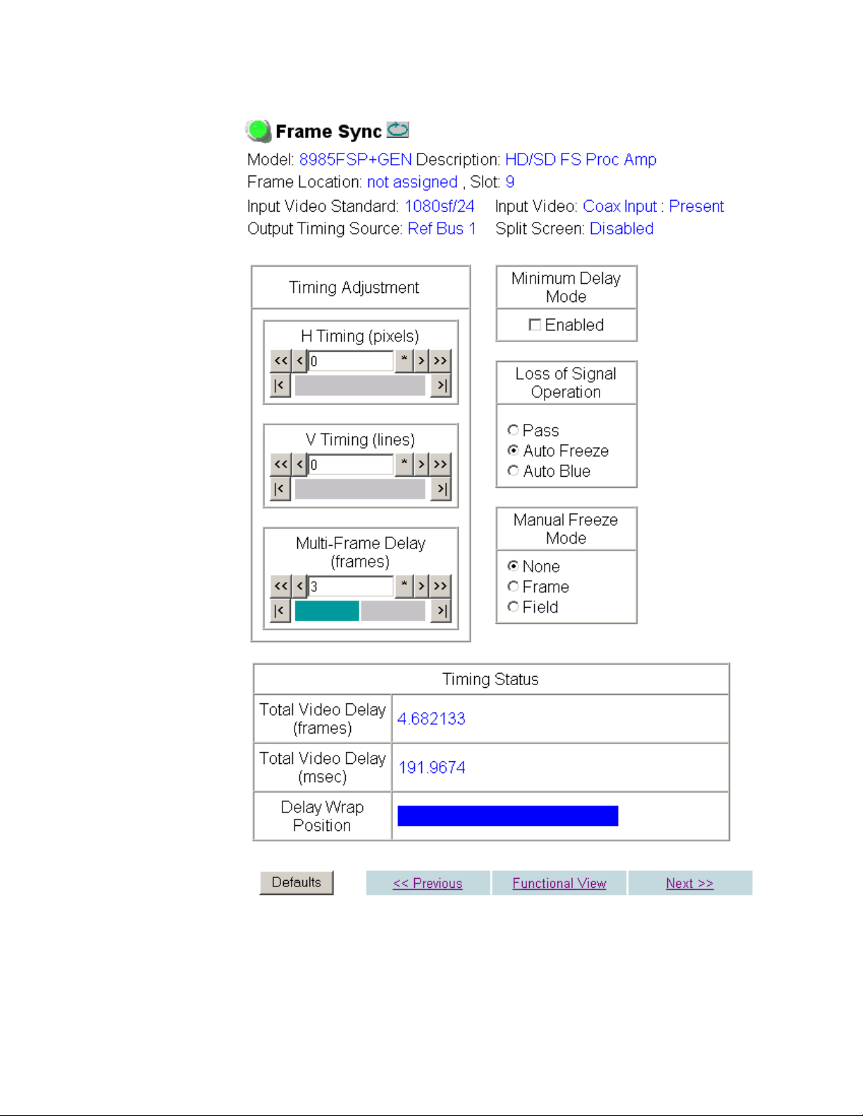
Frame Sync Web Page
The Frame Sync web page (Figure 23 on page 50 for Local or Reference Bus
reference and Figure 24 on page 51 for Input reference) provides horizontal
and vertical timing and loss of signal contr
Note The controls available on the Frame Sync page depend on the Output Timing
Source selected on the System Config web page.
Timing Adjustment
When the Frame Sync option is present and the Local output timing source
is selected, horizontal and vertical timing adjustments can be made on the
output video as required relative to the external reference with the following controls
H Timing (Pixels) – the horizontal timing can be adjusted in pixels relative
•
to the external reference.
V Timing (Lines) – the vertical timing can be adjusted in lines relative to
•
the external reference.
ols for the 8985FSP module.
•
Multi-Frame Delay – this control allows you to add up to 6 frames of delay.
When the H and V Timing controls are set to maximum, the total delay
of the module will be 8 frames (when
selected).
Minimum Delay Mode is not
Minimum Delay Mode
A Minimum Delay Mode can be enabled to bypass portions of the frame
sync memory to allow an absolute minimum amount of delay through the
module. It is a special mode allowing the user to select a throughput delay
of about 300 pixel periods when the input is synchronous and its position
with respect to the reference is well known. To enable this mode, check the
Enabled checkbox.
Note Delay can be added when in Minimum Delay Mode without causing video dis-
tortion up to one line short of a whole frame period of user delay. For normal
delay operations, Minimum Delay mode should be disabled.
Loss of Signal Operation
Set the operation to be performed by the module upon loss of input signal
when a Local external reference is present (
When there is no external reference (output tim
module will default to pass the signal to the output.
Auto Blue, Auto Freeze, or Pass).
ing set to Input), the
Manual Freeze Mode
Select one of the radio buttons (Frame or Field) to perform a manual freeze
on the output
48 8985FSP/FS — Instruction Manual
.
Page 49

Configuration
Timing Status
In the Timing Status table, Total Video Delay is reported through the module
in numerical format in frames and in microseconds as shown in the
example in
The Delay Wrap Position indicator will display with a blue bar, the fraction of
the final frame of actual video delay through the frame sync. It will not
indicate if multiple frames have been selected with the Multi-Frame Delay
control.
For example, with 1080i video and Minimum Delay Mode not selected, if
600 lines plus 5 frames of delay is entered by the user, that actual delay
through the module will be anywhere from about 6 to 7 frames depending
on the following conditions:
• If the module is in Delay (Input-Timed) Mode, the delay through the
module will be about 6.5 frames, and the Delay Wrap Position will be
at about 50% of full scale.
• If the module is in Frame Sync (Genlock) Mode, the delay through the
module will be about 6.5 frames if the input video has zero delay with
respect to the genlock reference frame position, and the Delay Wrap
Position will be at about 50% of full scale. As this input video delay
with respect to the genlock reference frame position is changed from
-0.5 to +0.5 frame periods, the delay through the module will change
from about 6 to 7 frame periods, with the Delay Wrap Position changing
from about 0 to 100% of full scale.
Figure 23 on page 50.
In summary, the Electrical Length of the module can be estimated as the following:
• 1 frame minus 5 lines (Minimum Delay Mode not selected), or
• 150 pixels (Minimum Delay Mode selected) + Multi-Frame Delay +
Delay Wrap Position (% of full scale) X (1 frame period).
8985FSP/FS — Instruction Manual 49
Page 50
Configuration
Figure 23. Frame Sync Web Page – Local or Frame Bus Reference
50 8985FSP/FS — Instruction Manual
Page 51
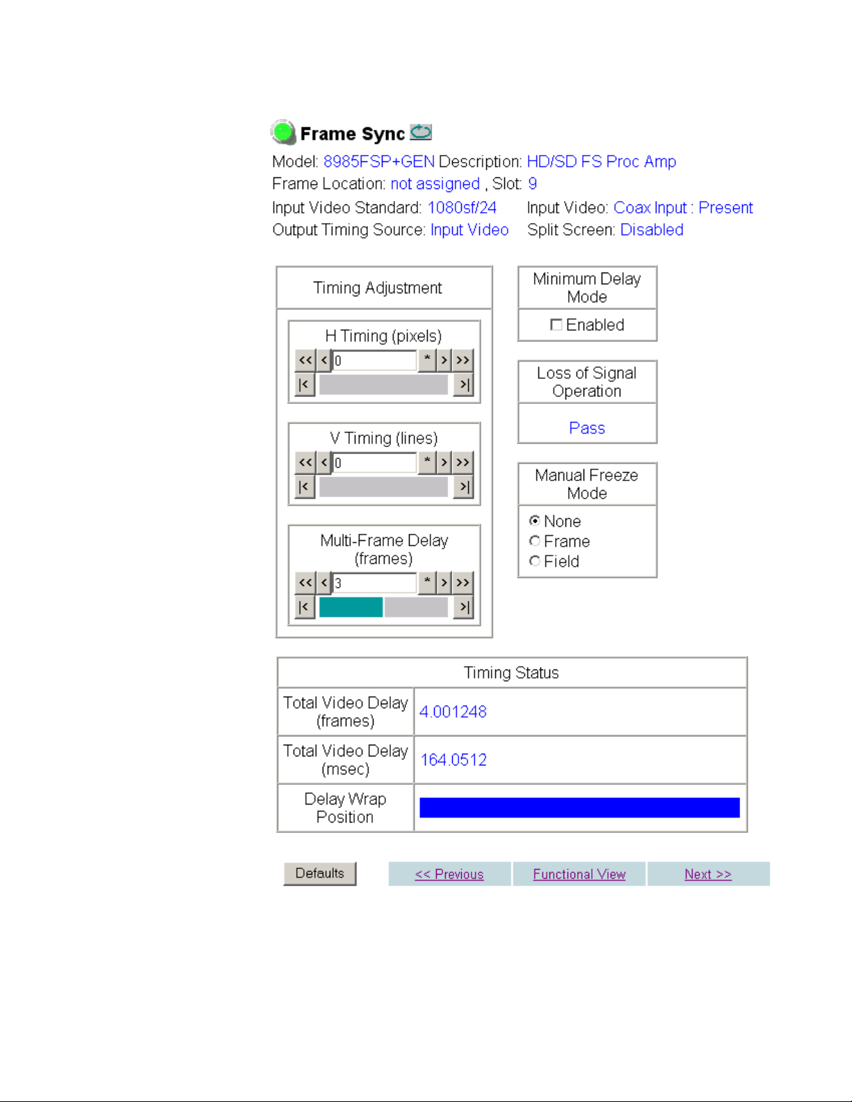
Figure 24. Frame Sync Web Page – Input Reference
Configuration
8985FSP/FS — Instruction Manual 51
Page 52

Configuration
Use
this
link
Color Correction Web Page
On the 8985FSP module, use the Color Correction web page (Figure 25 on
page 53) to make RGB gain, offset and gamma corr
control the Split Screen function.
The Color Correction processing must be enabled before adjustments can
be made. Select the
Color Correction
The Color Correction section provides the following RGB controls:
Gain Adjustments – set the gain from 0 to 200% for the R, G, and/or
•
B channel with the corresponding control or adjust all of the gains
together by adjusting the
Offset Adjustments – set the offset from ± 100% for the R, G, or B channel
•
with the corresponding control or adjust all of the offsets together by
adjusting the
Gamma Correction – set gamma correction with the R Gamma Correction,
•
G Gamma Correction, and/or B Gamma Correction or adjust all channels
together using the
above 1.0, brightens the gray intensity. Lowering the gamma below 1.0,
darkens the gray intensity.
RGB Offset control.
ection adjustments and
VCC Enable checkbox to enable these controls.
Total Gain control.
Total Gamma Correction control. Raising the gamma
Split Screen
Use a horizontal or vertical split screen to compare the unprocessed input
video (top or right) to the processed output video (bottom or left). This
control is duplicated and tied together with the Split Screen controls on the
System Config and Video Proc web pages. Changes made on any one of the
Split Screen controls will control all three screens.
Split Enable – enable the split screen by checking the Split Enabled
•
checkbox.
Orientation – select the orientation of the split screen with the Vertical or
•
Horizontal radio button.
Position – use this control to set the amount of horizontal or vertical split
•
(10 to 90%) of unprocessed video to appear on the screen.
52 8985FSP/FS — Instruction Manual
Page 53
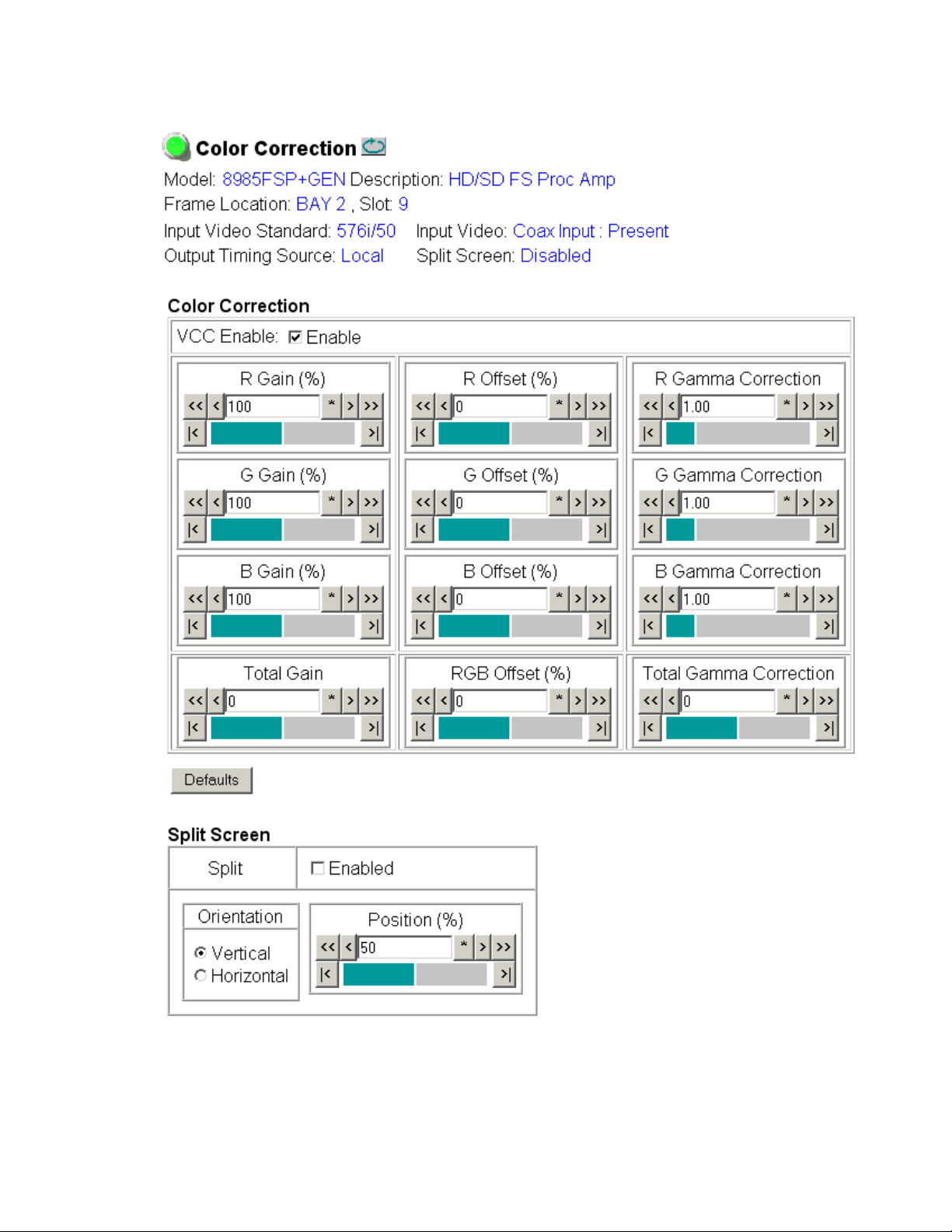
Figure 25. Color Correction Web Page
Configuration
8985FSP/FS — Instruction Manual 53
Page 54

Configuration
Use
this
link
Video Proc Web Page
On the 8985FSP module, the Video Proc web page (Figure 26 on page 55)
provides overall video processi
SD signal.
Video Processing Controls
The Video Proc controls must be enabled by checking the VPA Enable
checkbox.
The following controls are provided for video processing:
VPA (Video Proc Amp)
Use the controls below to adjust the video proc amp:
VPA Enable checkbox – to enable the video proc amp controls, select the
•
VPA Enable checkbox.
Y/Cb/Cr Gain – set the gain for the Y, Cb, or Cr channel from 0 to 200% with
•
the corresponding control or adjust all gains together by using the
Gain
control.
ng and Y/C clipping controls for the HD or
Total
Y/Cb/Cr Offset – set the offset ± 100% for the Y, Cb, and Cr channels with
•
the corresponding control.
Color Saturation – adjust the percentage of color saturation relative to
•
100%.
Y/C Clip Controls
Use the following clipping controls to adjust levels on the output signal:
Clip Enable checkbox – to enable the clip controls, select the Clip Enable
•
checkbox.
•Use the
(white) of the luminance signal (positive excursions) from 50 to 109%.
•Use the
(black) of the luminance signal (negative spikes and Super Black) from
-7 to +50%.
•Use the
(white) of the chrominance channel (clips white and reduces overall
saturation level to fit within clip) from 50 to 109%.
Y White Clip (%) control to set the clipping level for the top end
Y Black Clip (%) control to set the clipping level for the bottom end
C White Clip (%) control to set the clipping level for the top end
54 8985FSP/FS — Instruction Manual
Page 55
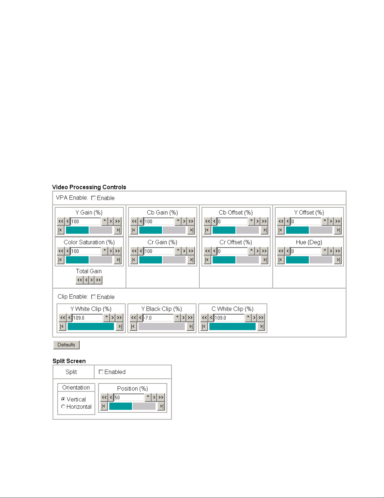
Configuration
Split Screen
Use a horizontal or vertical split screen to compare the unprocessed input
video (top or right) to the processed output video (bottom or left). This
control is duplicated and tied together with the Split Screen controls on the
System Config and Color Correction web pages. Changes made on any one
of the Split Screen controls will control all three screens.
• Split Enable – enable the split screen by checking the Split Enabled
checkbox.
Orientation – select the orientation of the split screen with the Vertical or
•
Horizontal radio button.
Position – use this control to set the amount of horizontal or vertical split
•
(10 to 90%) of unprocessed video to appear on the screen.
Figure 26. Video Proc Web Pager
8985FSP/FS — Instruction Manual 55
Page 56
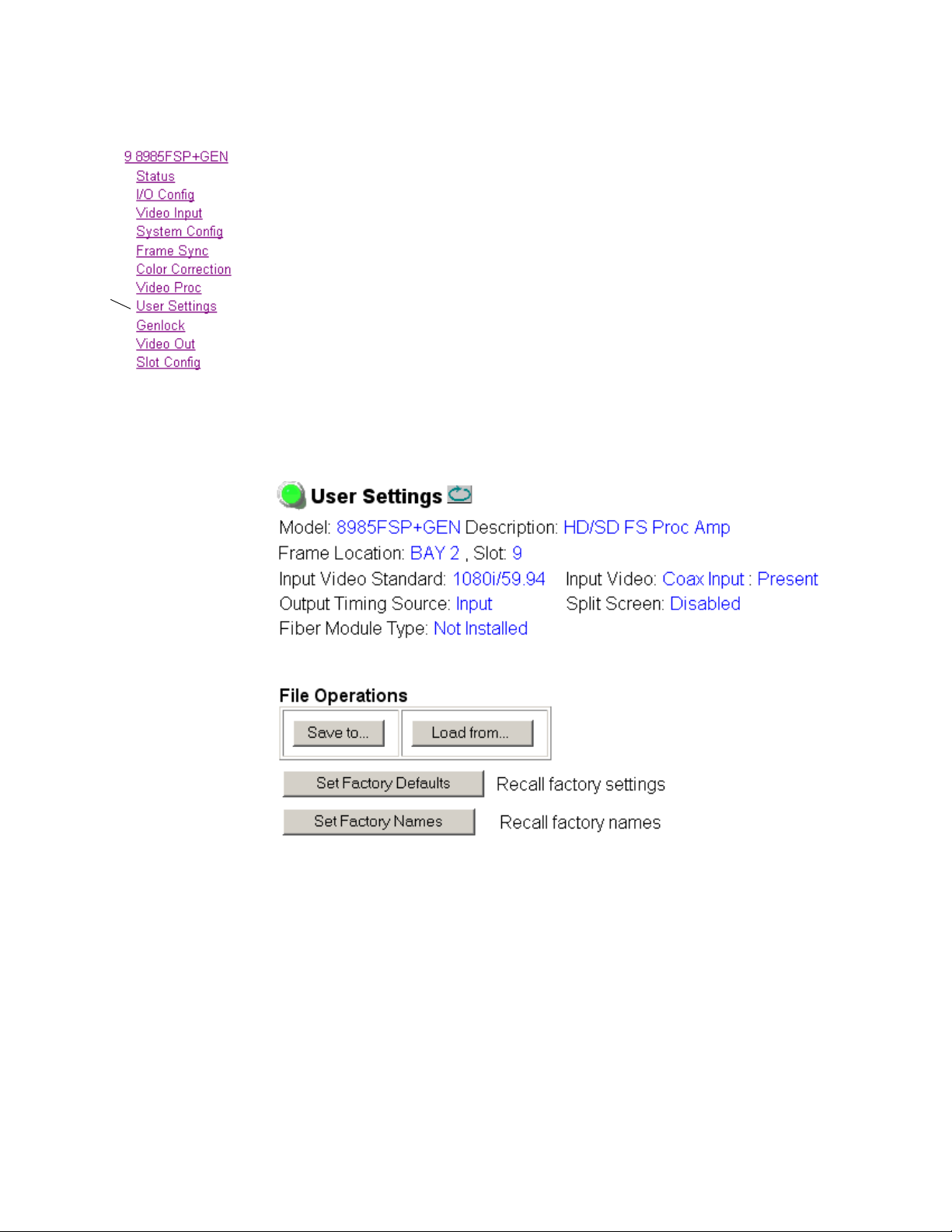
Configuration
Use
this
link
User Settings Web Page
The User Settings web page (Figure 27) provides a save/load function for
configuration files and a way to recall
signal names for the entire module.
Recall Factory Defaults and Names
Use the two button at the bottom of the web page to do the following:
Set Factory Defaults – select the Set Factory Defaults button to recall factory
•
settings to the module. Defaults for all module parameters are listed in
Table 9 on page 75.
Set Factory Names – select the Set Factory Names button to recall factory
•
signal names to the module. Defaults for all signal names are displayed
on the I/O Config web page shown in Figure 17 on page 40.
Figure 27. Set Factory Defaults Web Page
factory defaults parameters and
56 8985FSP/FS — Instruction Manual
Page 57
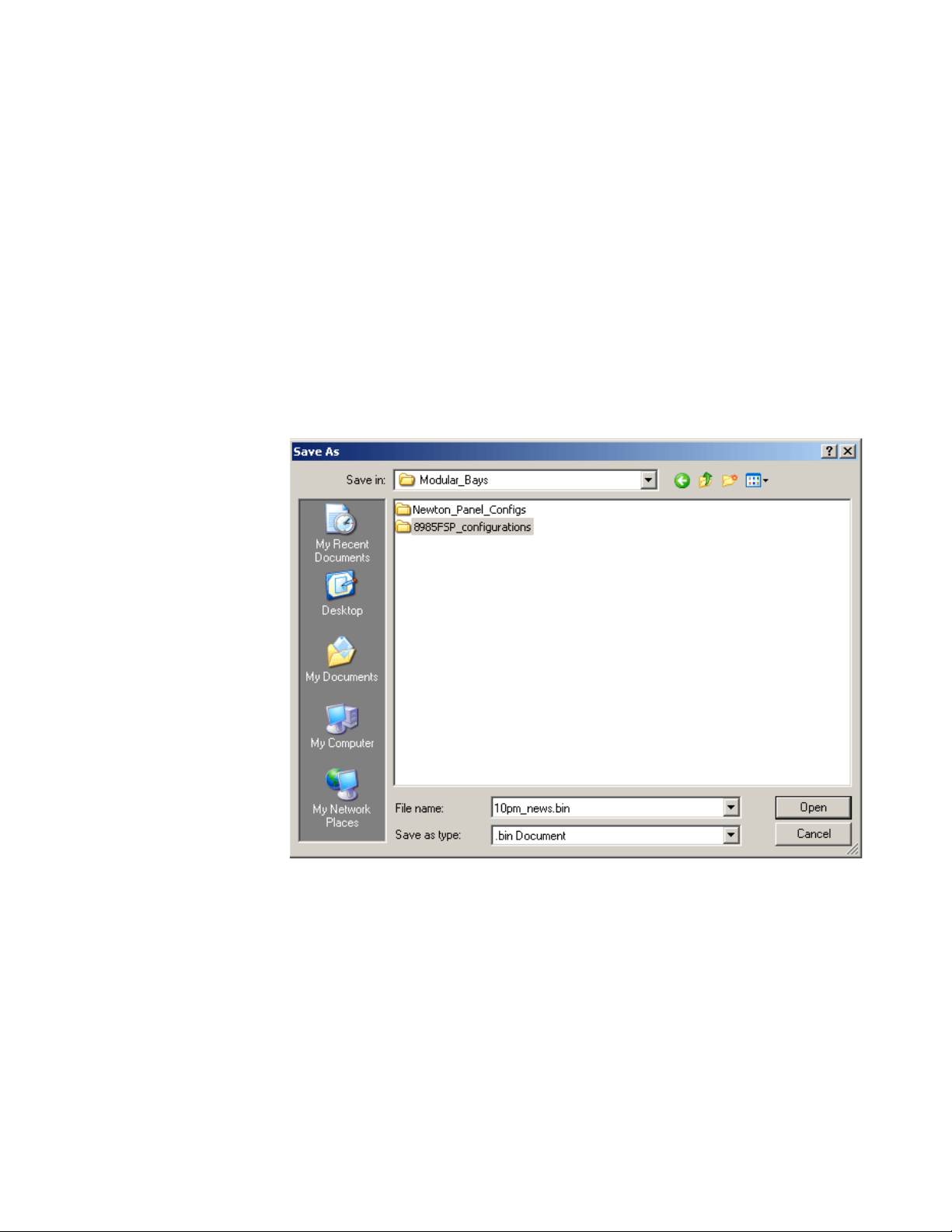
Configuration
File Operations
Configuration files from the 8985 module may be saved to a file and stored
offline for later recall.
To save a file, do the following:
1. Save the current configuration on the module to a file by selecting the
Save to... button which will bring up the File Download screen (not
shown).
2. In the File Download screen select Save.
3. This will bring up the Save As screen shown in Figure 28.
4. Enter a name in the File name field. This file is saved as a .bin type.
Figure 28. Save As Screen.
To load and recall a file, do the following:
1. Selecting the Load From... button on the User Settings web page
(Figure 27 on page 56) which will bring up the Load Settings web page
shown in Figure 29 on page 58.
2. Enter a path and file name or select Browse... to locate the directory
where the files have been saved.
8985FSP/FS — Instruction Manual 57
Page 58
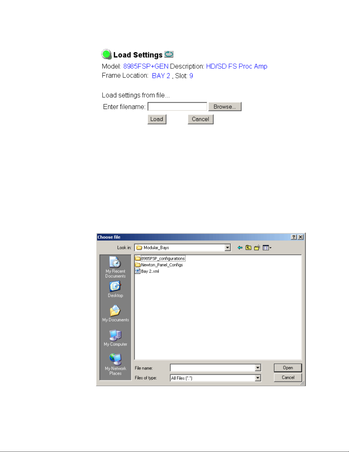
Configuration
Figure 29. Load Settings Web Page.
3. This will bring up the Choose File screen shown in Figure 30.
4. Select a file to load and then press Open to bring the file into the filename
field.
5. Press the Load button in the Load Settings web page (Figure 29) to load
the file to the module.
Note The parameters stored in this file will immediately be loaded to the module.
This could change the status of the output so be sure to be aware of the
changes or be off air before uploading a configuration file.
Figure 30. Choose File Screen
58 8985FSP/FS — Instruction Manual
Page 59

Genlock Web Page
Use
this
link
The Genlock web page (Figure 31 on page 60) is present on 8985FSP + GEN
and 8985FS + GEN modules when an 890
Configuration
0GEN-SM submodule is installed.
Refer to the 8900GEN-SM Installation Manual a
details for configuring the 8900GEN-SM submodule.
This web page provides reporting status for
items:
• Genlock – reports status of Genlock function as
• Status – reports whether the reference input is
• Firmware Version – reports the firmware version of the 8900GEN-SM
submodule installed on this 8985FSP module.
• Hardware Version – reports the hardware version of the 8900GEN-SM
submodule installed on this 8985FSP module.
• Ref Input Standard – reports the reference input standard as detected
by the 8900GEN-SM submodule that is connected to the Genlock Loop
on the 8900GFR-R rear module.
• Ref Input Frame Rate – reports the frame rate of the reference input as
detected by the submodule.
• Output Bus Frame Rate – reports the frame rate being output on the
frame bus.
• Output Bus – reports the reference bus (Ref Bus 1 or Ref Bus 2) being
output from the submodule.
vailable online for complete
the following genlock status
Enabled or Freerun.
Locked or Not Locked.
Genlock Control
The following controls are available for configuring the Genlock submodule:
Enable or Freerun – select one of the radio buttons to enable the Genlock
•
submodule or allow the reference to freerun.
•
Input Standard Selection – use this control to set the input standard needed
for the reference input. Refer to Table 4 on page 61 for important notes
on standard selection.
Loop Bandwidth – set this control for either fast locking (Fast Lock) to the
•
reference or for the lowest jitter performance (
the stability of the reference signal being used.
For example, if Low Jitter is selected and the Status is still
one minute has passed, the input reference has excessive wander that
cannot be tracked in Low Jitter mode. Switch to
Status is
8985FSP/FS — Instruction Manual 59
Locked after about 10 seconds.
Low Jitter) depending on
Invalid after
Fast Lock and verify
Page 60
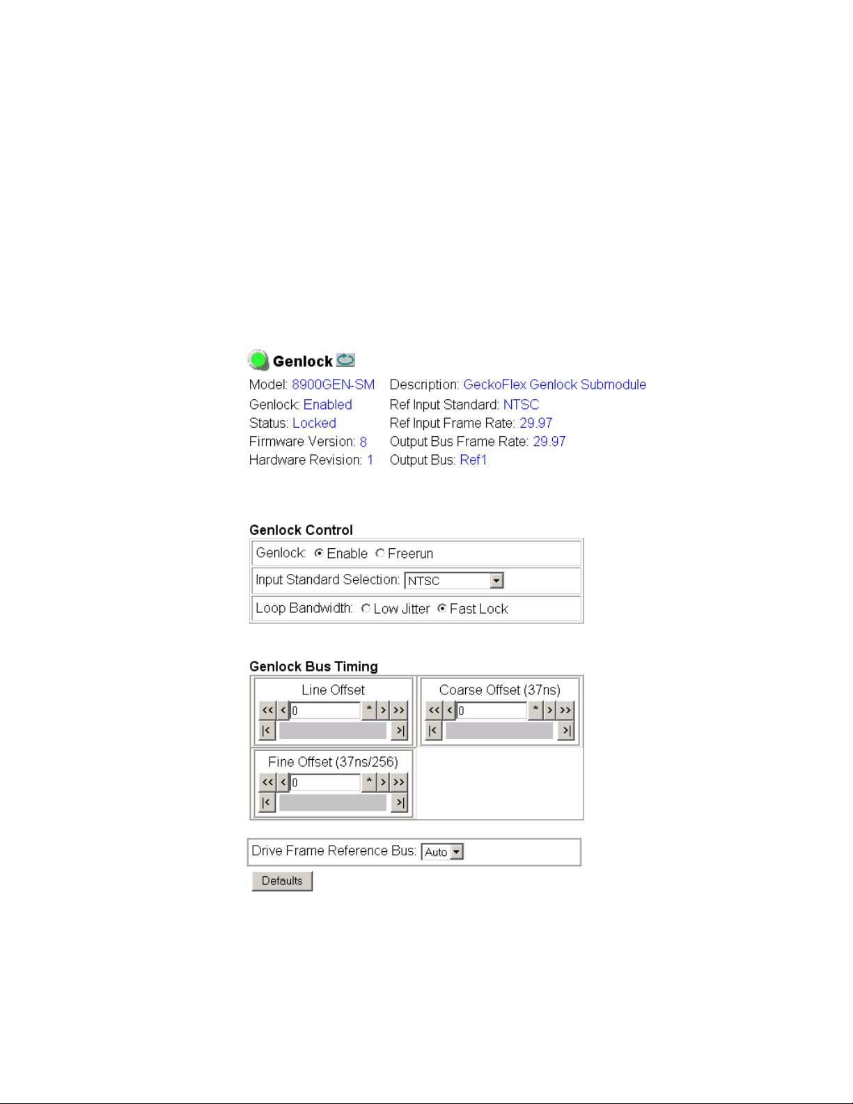
Configuration
Genlock Timing
Use the following controls to adjust the output timing of the genlock reference signal from this submodule:
• Line Offset – adjust the reference timing stream by standard definition
line steps up to one full frame.
Coarse Offset – provides coarse adjustment of the reference timing stream
•
by 37 ns steps up to one line.
Fine Offset – provides fine adjustment of the reference timing stream by
•
steps up to 37 ns.
Figure 31. Genlock Web Page
60 8985FSP/FS — Instruction Manual
Page 61

Configuration
The external reference fed to the Genlock submodule must be configured to
one of the frame rates in the reference Input Standard Selection pulldown
on the Genlock web page.
Tab le 4 lists the available frame rates in the pull-
down and the compatible reference inputs that will report a locked condition on the Genlock web page.
Note If the Input Selection Standard selected on the Genlock web page does not
match the reference input exactly, a warning will be generated.
Table 4. Reference Frame Rate Compatibility
Genlock Input Standard
Selection
NTSC
PAL
1080i 59.94 TLS
720p 59.94 TLS
1080i 50 TLS
720p 50 TLS
1080p 24 TLS
1080sf 24 TLS
AES 48K
Reference
Detected
NTSC None
1080i 59.94 TLS Yes
720p 59.94 Yes
PAL None
1080i 50 TLS Yes
720p 50 TLS Yes
1080i 59.94 TLS None
NTSC Yes
720p 59.94 TLS Yes
720p 59.94 TLS None
NTSC Yes
1080i 59.94 TLS Yes
1080i 50 TLS None
PAL Yes
720p 50 TLS Yes
720p 50 TLS None
PAL Yes
1080i 50 TLS Yes
1080p 24 TLS None
1080sf 24 TLS Yes
PAL Yes
1080i 50 TLS Yes
720p 50 TLS Yes
1080sf 24 TLS None
1080p 24 TLS Yes
PAL Yes
1080i 50 TLS Yes
720p 50 TLS Yes
AES 48K None
AES 96K Yes
Word Clock 48K Yes
Work Clock 96K Yes
Mismatch
Warning
1
1
1
1
1
1
1
1
1
1
1
1
1
1
1
1
1
1
1
1
1
1
1
8985FSP/FS — Instruction Manual 61
Page 62

Configuration
Table 4. Reference Frame Rate Compatibility
Genlock Input Standard
Selection
AES 96K
Word Clock 48K
Word Clock 96K
1
This input standard will lock but will generate a Warning on both the Genlock and Status web
pages but will not affect the locked condition.
Reference
Detected
AES 96K None
AES 48K Yes
Word Clock 48K Yes
Work Clock 96K Yes
Word Clock 48K None
AES 48K Yes
AES 96K Yes
Work Clock 96 Yes
Word Clock 96K None
AES 48K Yes
AES 96K Yes
Work Clock 48K Yes
Mismatch
Warning
1
1
1
1
1
1
1
1
1
62 8985FSP/FS — Instruction Manual
Page 63
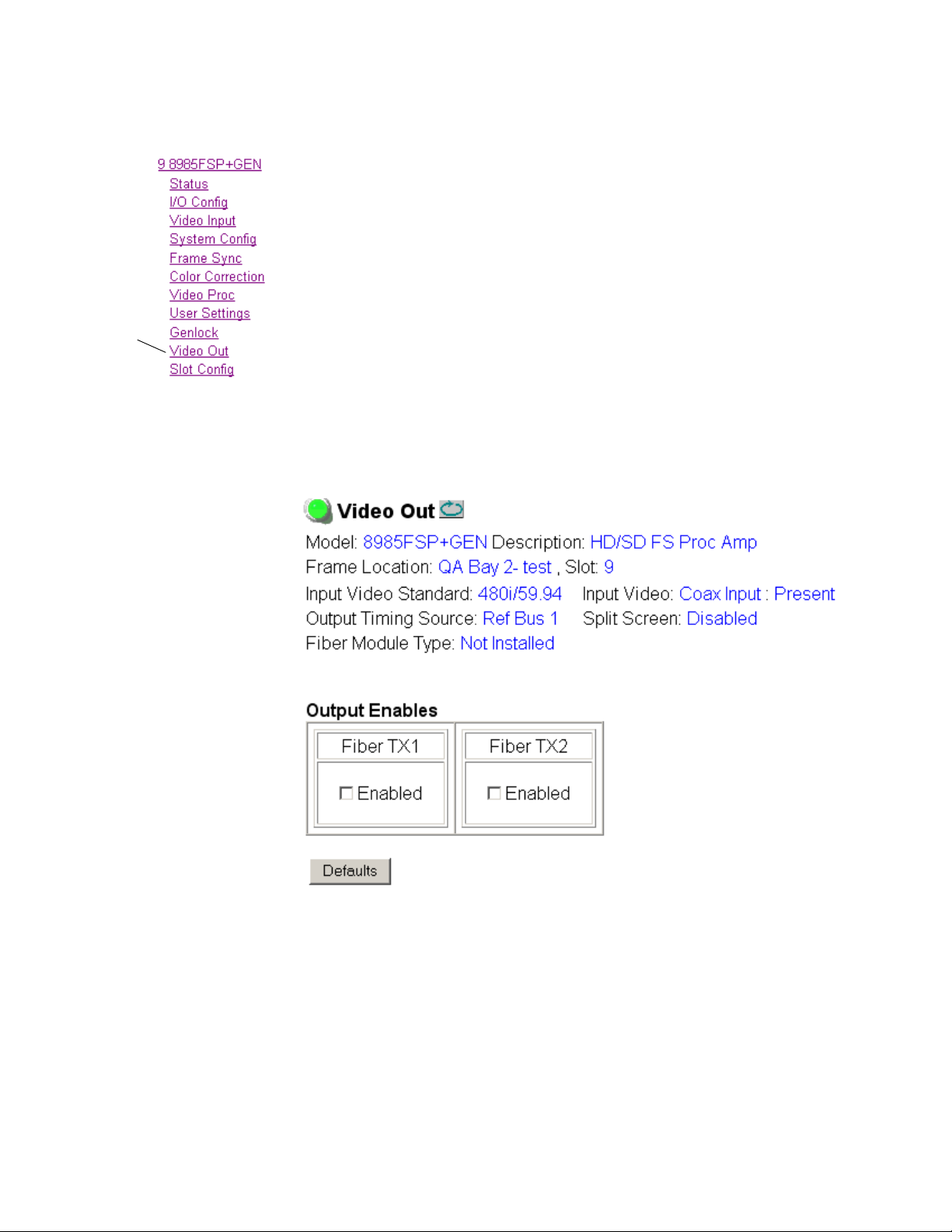
Video Out Web Page
Use
this
link
Use the Video Out web page (Figure 32) to enable or disable the SFP Fiber
Optic submodule outputs when present and disable
desired.
Note Fiber optic outputs will be present when either a Dual Transmitter or Trans-
ceiver Fiber Optic submodule is installed.
Output Enables
This section provides the following for the video output signal:
Fiber TX1 – check the Enabled checkbox to enable the output (Dual Trans-
•
mitter SFP submodule installed).
Fiber TX2 – check the Enabled checkbox to enable the output (Transceiver
•
or Dual Transmitter SFP submodule installed).
Figure 32. Video Out Web Page
Configuration
EDH insertion if
8985FSP/FS — Instruction Manual 63
Page 64

Configuration
Use
this
link
Slot Config Web Page
Use the Slot Config web page shown in Figure 33 on page 65 to perform the
following functions on the module.
Note This Slot Config web page reflects the use of 8900NET (Net Card) software
version 4.3.0.
Locate Module
Selecting Flash from the Locate Module pulldown flashes the yellow COMM
and CONF LEDs on the front of the module so it can be located in the
frame.
Slot Identification
You may identify the module by typing a specific name in the Name field.
The assigned name is stored on the 8900NET module and travels with the
8900NET module if it is moved to another frame. Select
factory default module name.
Default to enter the
An asset identification may be
entered in the Asset Tag field. This will appear
on the module Status web page and in the NetConfig inventory report.
Slot Memory
The slot configuration for each media module is automatically polled and
refreshed periodically (about every 50 minutes) by the 8900NET module
when the
page (with 4.3.0 software) and/or the
media module Slot Config web page is selected.
When the
web page has been selected, the current configuration from that module is
saved in slot memory on the 8900NET module. This allows the current
module to be removed and when another module of the same part number,
and software version is installed, the configuration saved to the 8900NET
module will be downloaded to the installed module. The
checkbox must be selected before the current module with the saved configuration is removed.
Note Make sure all modules of the same model type are running the same software
Always Slot Refresh checkbox on the 8900NET Configuration web
Restore upon Install checkbox on any
Restore upon Install checkbox on any media module Slot Config
Restore upon Install
version and have the same part number silk-screened on the printed circuit
board. Downloading a configuration to a module with a different software
version or part number can produce unexpected results.
If a different type of module is installed in this slot, a warning message will
state that the original module type has been replaced with another module
type. In this case, a
Clear button will appear allowing you to clear the stored
configuration from the previous module.
64 8985FSP/FS — Instruction Manual
Page 65
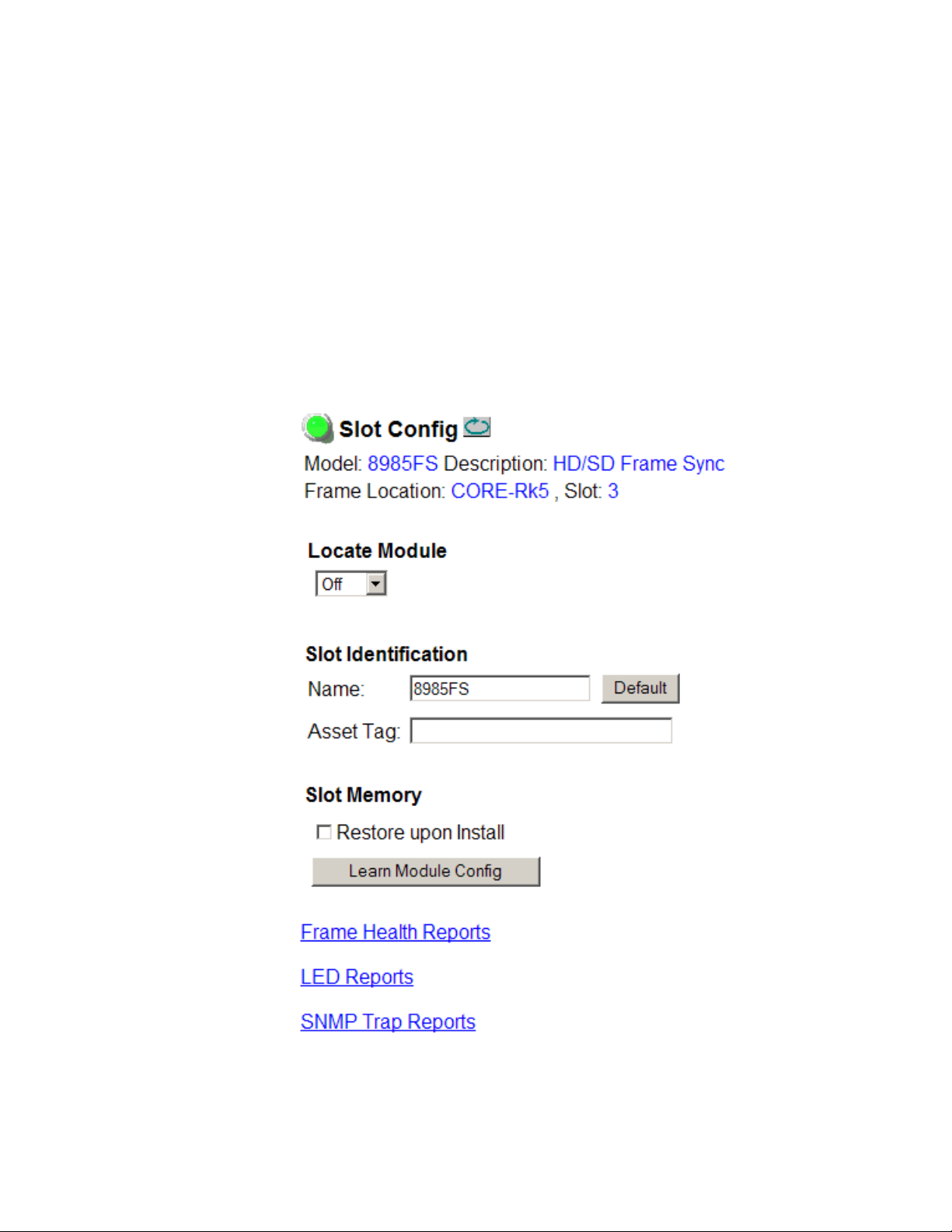
Configuration
You may also select the Learn Module Config button at any time to save the
current configuration for this slot. The configuration is saved on the
8900NET module. If the 8900NET module is removed or powered down,
the stored configurations are not saved.
When no Restore upon Install checkboxes on any of the media module Slot
Config web pages are selected and the
8900NET Configuration web page is unchecked, the slot refresh polling
function on the 8900NET module will be disabled. See the
checkbox description in the 8900NET (Net Card) Network Interface Module
Instruction Manual for more details.
Note Uncheck the Restore Upon Install button before downloading new software.
Figure 33. Slot Config Web Page
Always Slot Refresh checkbox on the
Always Slot Refresh
8985FSP/FS — Instruction Manual 65
Page 66

Software Updating
Frame Health Reports Link
Select the Frame Health Reports link to open the 8900NET module Frame
Alarm Reporting web page. This web page allows configuration of the
alarms and warnings that are reported to the external Frame Health Alarm
connector on the rear of the GeckoFlex frame.
LED Reports Link
Select the LED Reports link to open the 8900NET LED Reporting web page.
Normally, every module in the frame will report to the 8900NET module
any Fault, Signal Loss, Reference Loss, or Config Error conditions. These
conditions will be reflected by the status LEDs on the 8900NET module.
Using this web page, any of these conditions on this module and other
frame components such as the power supplies and fans, can be disabled
from being reported to the 8900NET module.
SNMP Trap Reports Link
Select the SNMP Trap Reports link to open the 8900NET SNMP Reporting
web page. This link will only be present when SNMP Agent software has
been installed on the 8900NET module. This web page allows configura
tion of which alarms and warnings that are reported to the SNMP management software.
-
Refer to the 8900NET Instruction Manual for complete details on using the
8900NET web pages.
Software Updating
Software updating of the 8985FSP/FS modules is done using the NetConfig Networking Application PC option. This application is available
free of charge from the Grass Valley web site.
Software updating requires the presence of the 8900NET (Net Card)
module running software version 4.3.0. Refer to
page 11 for acquiring the latest version 8900NET software.
All modular product documentation can be found in PDF format on the
Grass Valley web site at this link:
www.grassvalley.com/docs/modular
Software Requirements on
66 8985FSP/FS — Instruction Manual
Page 67

Specifications
Table 5. 8985FSP/FS Specifications
Parameter Value
Serial Digital Input
Number and type of input 1 non-isolated terminating BNC
Input impedance 75 ohm
Input return loss > 15 dB from 5 MHz to 1.5 GHz
Input signal level 800 mV ± 10%
Input DC tolerance +/- 0.25 mV maximum
Serial mode hum voltage 1 V p-p to 60 Hz maximum
Common mode rejection ratio (CMMR) N/A
Auto equalization 325 meters of Belden 1694A or 270 Mb/s
Reclocking Yes
Input lock range ± 100 PPM
Input signal type
Reference Signal Input (8900GEN-SM Genlock Submodule Installed)
Signal Type:
Analog color black 525i/59.9(NTSC); 625i/50(PAL-B); SMPTE318M
Tri-level sync 720p59.94; 1080i59.94, 720p50, 1080i50, 1080p24, 1080sF/24
4 V composite sync Not supported
Active video Not supported due to effects on timing
Reference signal level 300 mV p-p ± 6 dB
Reference signal to noise ration (S/N) > 46 dB S/N
Serial Digital Outputs
Connector type Coax BNC, optional fiber optic SFP
Number of outputs 4
Output impedance 75 ohm
Return loss > 15 dB 5 MHz-270 MHz
Output signal level SDI 800 mV p-p, ± 10%
Rise/fall time (20-80%) 140 ps for HD
Output jitter
(FS mode, in low jitter mode)
125 meters of Belden 1694A for 1.5 Gb/s
HD-SDI:
• 1080i 59.94/50
• 1080p24/sF24
• 720p 59.94/50
SD-SDI:
• 480i/59.94 (NTSC)
• 576i/50 (PAL-B)
(NTSC with 10 field AES ID)
> 15 dB typical 270 MHz to 1.5 GHz
500 ps for SD
< 0.2 UI HD > 100 kHz
< 1.0 UI HD 10 Hz-100 kHz
< 0.2 UI SD > 1 kHz
< 0.2 UI HD 10 Hz-1 kHz
Specifications
8985FSP/FS — Instruction Manual 67
Page 68
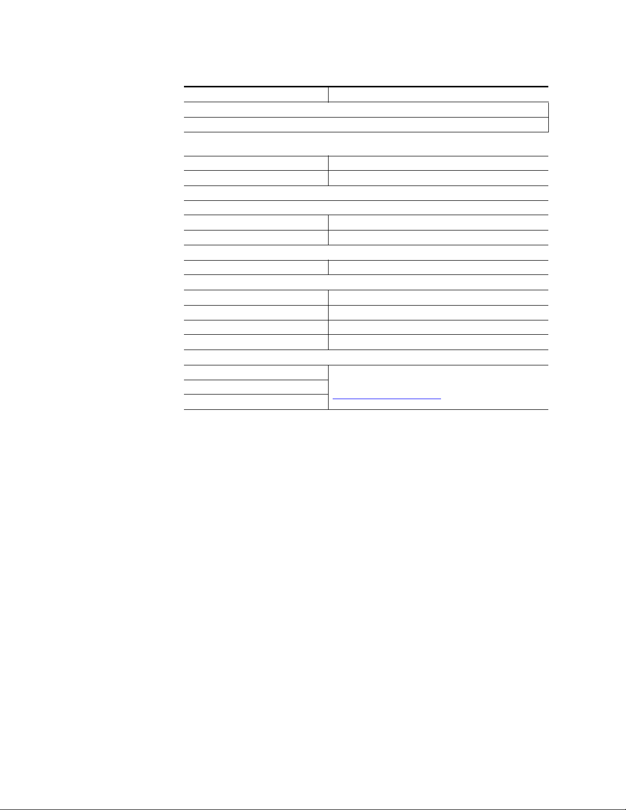
Specifications
Table 5. 8985FSP/FS Specifications - (continued)
Parameter Value
Electrical Length
Input to output delay: Default with zero user input delay
In delay mode or in genlock mode with zero input video delay with respect to genlock frame position
(see Table 6 on page 69)
Full-frame mode 1 frame periods in all formats
Minimum delay mode ~ 300 pixel periods in all formats
Input to output delay: User input delay in pixel steps ranging from 0 to 7 frames
In delay mode or in genlock mode with any input video delay with respect to genlock frame position
Full-frame mode 1 frame minus 5 lines to 8 frames minus 5 lines
Minimum delay mode 150 pixels to 7 frames
1
2
3
Power
Power dissipation < 8.0 W (with Genlock and fiber optic submodules)
Mechanical
Frame type GeckoFlex
Number of slots required 1 slot
Rear module type 8985FS or 8985FSP: 8900GFR-R
Rear module retainer clip screw torque 4-5 inch-lb./0.45-0.6Nm
Environmental
Frame temperature range
Operating humidity range
Non-operating temperature
1
The User input delay is specified as 0 to 6 full frames. plus one frame in pixels and lines. The Delay Wrap Position on the
Frame Sync web page roughly indicates what fraction of that last frame of adjustable delay is being used. Because the input
video delay with respect to genlock frame position can vary, the Delay Wrap Position with respect to User Input Delay will
vary.
2
Full Frame Mode always has at least 1 frame minus 5 lines of electrical length.
3
Video distortion can occur with User Input Delay that gives ~150 pixels of electrical length. Increase the delay to give a
total of ~300 pixels of delay for the optimum minimum delay setting.
Refer to GeckoFlex Frames 8900FX/FF/FFN Signal Processing
Systems Instruction Manual at:
www.grassvalley.com/docs/modular
68 8985FSP/FS — Instruction Manual
Page 69
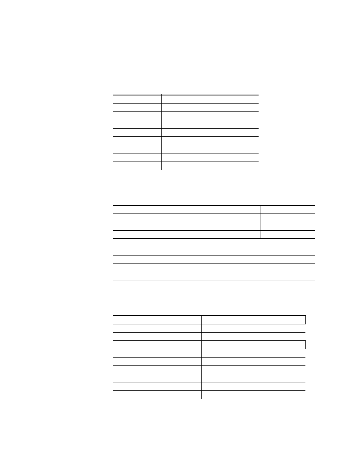
Specifications
The frame phase relationship between the SDI video stream and the analog
reference signal is established according to SMPTE RP 168-2002. This
defines the SDI video frame start occurring N pixel periods before the
frame start of the analog video reference signal. N is defined for each video
format in
Table 6. Frame Phase Relationship
Tab le 6.
Format Standard N
408i59.94 SMPTE 125M-1995 16
576i50 Rec. ITU-R BT.656-4 12
1080i59.94 SMPTE 274M-1998 88
720p59.94 SMPTE 296M-2001 110
1080i50 SMPTE 274M-1998 528
720p50 SMPTE 296M-2001 440
1080sF24 SMPTE 274-1998 638
1080p24 SMPTE 274-1998 638
Table 7. SFP Receiver/Transceiver Fiber Optic Submodule Specifications
Model Number SFP-13103G-M1DRX SFP-13103G-M1TRX
Low wavelength 1260nm 1260nm
High wavelength 1620nm 1620nm
Receiver channels 2 1
Connector type LC
Fiber support Single mode
Data rate 50Mb/s to 3Gb/s
Maximum distance @ 3Gb/s 10km
Minimum distance 30km
Tab l e 8 . S F P Tr a ns m it te r /Tr a ns c ei v er Fiber Optic Submodule Specifications
Model Number SFP-13103G-M1DTX SFP-13103G-M1TRX
Wavelength 1 1310 nm 1310 nm
Wavelength 2 1310 nm N/A
Transmit channels 2 1
Connector type LC
Fiber support Single-mode
Data rate 143 Mb/s to 2.97 Gb/s
Power output -5 to 0 dBm (-2dBm typical)
Maximum distance 10 km
Maximum distance 20 km
1
The 1310 nm Dual Transmitter (SFP-13103G-M1DTX) and Transceiver (SFP-13103G-M1TRX) require no attenu-
ation between fiber transmitter and receiver connections at any length.
1
8985FSP/FS — Instruction Manual 69
Page 70

Status Monitoring Summary
Status Monitoring Summary
There are a number of ways to monitor frame and module status. These
methods are summarized here. For more detailed information, refer to the
8900NET (Net Card) Network Interface Module Instruction Manual and the
8900 Gecko or 8900 GeckoFlex Frame Instruction Manuals.
All modular product documentation is available on-line in PDF format at
this link:
www.grassvalley.com/docs/modular
The main status monitoring methods include the following:
• External frame alarm output on the rear of the 8900 frame with
reporting from the Module Health Bus and other frame status alarm
reports,
• LEDs on the Frame, 8900NET module, and individual frame media
modules,
• Web browser status reporting for each frame component, and
• SNMP traps, captured by Grass Valley’s NetCentral or another SNMP
Manager Application.
Note SNMP trap information is only available when an SNMP Agent has been
installed and configured.
External Frame Alarm
An external Frame Alarm output is available on pins 8 and 9 of the RS-232
connector on the rear of the frame. The Frame Alarm outputs a voltage
level indicating there is an alarm condition on the Module Health Bus or
one of the other frame components reported to the Frame Monitor module
in a Gecko 8900TF or GeckoFlex 8900FF frame or the 8900NET module in
an 8900TFN and GeckoFlex 8900FFN frame.
• The Module Health bus is a separate line on the frame motherboard
that provides a means for older or less capable modules (such as DAs
with no microprocessor) that cannot communicate over the Frame
(serial) bus to report warning and alarm conditions to the external
Frame Alarm. All media modules in the frame report a voltage level to
this line when a warning condition occurs on the module. The specific
warning or module location is not reported, only an indication that an
warning condition has occurred.
• Frame alarm reporting from other frame components can be enabled
and disabled using DIP switches on the Frame Monitor and 8900NET
module. For frames with an 8900NET module, the Frame Alarm
Reporting web page allows configuration of the alarms and warnings
that are reported to this external Frame Health Alarm.
70 8985FSP/FS — Instruction Manual
Page 71

LED Reporting
LEDs on the front of media modules, the Frame Monitor or 8900NET modules, and the front covers of the 8900TF/TFN and GeckoFlex FF/FFN
frames indicate status of the frame and the installed power supplies, fans
in the front covers, and module status. (The 8900TX-V/A and GeckoFlex
8900FX frames have no LED indicators on the front cover.)
LED reporting from the modules in the frame to the 8900NET module is
configurable using the 8900NET LED Reporting web page. LEDs for the
8900NET module are described in the 8900NET (Net Card) Network Interface
Instruction Manual.
The Status LEDs for this module are described in Operation Indicator LEDs
on page 23.
Web Browser Interface
The 8900NET module controls a web browser GUI that indicates frame and
module status on the following web pages:
Status Monitoring Summary
• Frame Status web page – reports overall frame and module status in
colored graphical and text formats. Refer to the Figure 10 on page 30 for
an example.
•Module Status web page (Figure 10 on page 30) – shows specific input
and reference signal configuration error status to the module along
with module status and information (part number, serial number, hardware version, software/firmware/boot versions, and Asset number (as
assigned on the Slot Config web page).
• A Status LED icon on each web page reflects the module status on the
module Status web page where warnings and faults are displayed and
is a link to the module Status web page.
SNMP Reporting
The Gecko 8900 Series system uses the Simple Network Monitoring Protocol (SNMP) internet standard for reporting status information to remote
monitoring stations. When SNMP Agent software is installed on the
8900NET module, enabled status reports are sent to an SNMP Manager
such as the Grass Valley’s NetCentral application.
Status reporting for the frame is enabled or disabled with the configuration
DIP switches on the 8900NET module. Most module status reporting items
can be enabled or disabled on individual configuration web pages.
8985FSP/FS — Instruction Manual 71
Page 72

Service
Service
Power-Up Diagnostic Failure
Troubleshooting
The 8985FSP/FS modules make extensive use of surface-mount technology
and programmed parts to achieve compact size and adherence to
demanding technical specifications. Circuit boards should not be serviced
in the field unless directed otherwise by Customer Service.
If the module has not passed self-diagnostics, do not attempt to troubleshoot. Return the unit to Grass Valley (see Module Repair below).
Electronic Circuit Breaker
An electronic circuit breaker on the module works during a fault condition
or an overcurrent to cut off power to the module in place of a fuse.
If power has been cut off to module, remove the module and replace it in
the frame to reset. If the problem persists contact Grass Valley Customer
Service.
Module Repair
If the module is still not operating correctly, replace it with a known good
spare and return the faulty module to a designated Grass Valley repair
depot. Call your Grass Valley Customer Service representative for depot
locations.
Contacting Grass Valley
If you need to contact Grass Valley for any module issues, refer to Contacting Grass Valley on page 4 at the front of this document for the Grass
Valley Customer Service Information number.
72 8985FSP/FS — Instruction Manual
Page 73

Functional Description
Genlock
Sub
Module
Equalizer
Option
HD/SD
SDI in
SD/HD
Optical In
4X HD/SD
SDI Out
Option
Ref In
Loop
Bus 1 Bus 2
Genlock
adjustment
Auto
Tracking
Delay
Synchronizer
RX 2
Fiber
Receiver
RX 1
RGB Video
Proc Amp
YUV Video
Proc Amp
Genlock
Sub
Module
Equalizer
Option
HD/SD
SDI in
SD/HD
Optical In
4X HD/SD
SDI Out
Option
Ref In
Loop
Bus 1 Bus 2
Genlock
adjustment
Auto
Tracking
Delay
Synchronizer
RX 2
Fiber
Receiver
RX 1
A block diagram of the 8985FSP module is shown in Figure 34.
Figure 34. 8985FSP Block Diagram
Functional Description
A block diagram of the 8985FS module is shown in Figure 35.
Figure 35. 8985FS Block Diagram
8985FSP/FS — Instruction Manual 73
Page 74

Functional Description
74 8985FSP/FS — Instruction Manual
Page 75

Configuration Parameter Summary
Ta bl e 9 provides a complete summary of the 8985FSP and 8985FS functions
and a comparison of the functionality available with the web page and
Newton control panel control type along with the ranges and default
values for each parameter.
Table 9. Summary of 8985FSP/FS Configuration Functions
Function
Type
Reference Signal Loss Reporting On On or Off
Coax Input Signal Loss Reporting On On or Off
Fiber Input 1 and 2 Signal Loss
Reporting
Video Input Selection
(Dual Receiver or Transceiver SFP
submodule installed.)
Input video standard Auto
Select primary output
timing source
Select secondary output timing
source
Test Output Color Bars signal Disabled Enable or Disable
Select switch to primary source
method
Select amount of delay for switching
back to primary
Default
On On or Off
COAX
Local
Local
Auto Auto or Manual
30 seconds 30 to 93.97 seconds
Range/Choices
Resolution
COAX,
Fiber RX 1,
or Fiber RX 2
Auto,
480i–(SD 59.94),
576i–(SD 50),
720p–(HD 59.94),
1080i–(HD 59.94),
720p–(HD 50),
1080i–(HD 50),
1080p–(HD 24), or
1080sf–(HD 24)
Local,
Ref 1,
Ref 2,
or Input
Local,
Ref 1,
Ref 2,
or Input
Web Page/
Function Name
I/O Config/
Genlock Ref In Loop
Reporting Enabled checkbox
I/O Config/
COAX In
Reporting Enabled checkbox
I/O Config/
Fiber Video in/Out 1 and 2
Reporting Enabled checkbox
Video In/
Video Input Select
Video Input Selection
radio button
System Config/
Video I/O Configuration
Input Video Standard pulldown
System Config/
Output Timing
Primary Source Selection
radio button
System Config/
Output Timing
Secondary Source Selection
radio button
System Config/
Test Output
Colorbars Enabled checkbox
System Config/
Reference Restore
Switch to Primary pulldown
System Config/
Reference Restore
Reference Switchback Delay (Seconds)
Newton
Control
Panel
N/A
N/A
N/A
N/A
InVidStd
OutClk
OutClk
ClrBars
RefSwBk
RefSwDly
8985FSP/FS — Instruction Manual 75
Page 76

Configuration Parameter Summary
Table 9. Summary of 8985FSP/FS Configuration Functions
Function
Type
Enable or disable split screen Disabled Enabled or Disabled
Split screen orientation Vertical Horizontal or Vertical
Split Screen position
(% of unprocessed video)
Enable minimum delay mode Disabled Enabled or Disabled
Horizontal Timing 0
Vertical Timing 0
Multi-Frame Delay control 0 0 to 6 Frames
Minimum Delay Mode enable Disabled Enable or Disable
Loss of signal operation AutoBlue
Manual freeze mode None
VCC (Video Color Correction)
enable control
Adjust R gain 100%
Adjust G gain 100%
Adjust B gain 100%
Adjust total gain 100%
Adjust R offset 0
Adjust G offset 0
Adjust B offset 0
Adjust total offset 0
Adjust R gamma 1.0
Default
50%
Enable Enable or Disable
Range/Choices
Resolution
10 to 90%
(1% steps)
0 to 857 pixels (525)
0 to 863 pixels (625)
(1 pixel steps)
0 to 524 lines (524)
0 to 624 lines (624)
(1 line steps)
Pass
Auto Freeze, or
Auto Blue
None,
Frame, or
Field
0 to 200%
(1% steps)
0 to 200%
(1% steps)
0 to 200%
(1% steps)
0 to 200%
(1% steps)
± 100%
(1% steps)
± 100%
(1% steps)
± 100%
(1% steps)
0 to 200%
(1% steps)
0.25 to 4.00
(0.01 unit steps)
Web Page/
Function Name
System Config/, or
Color Correction/, or
Video Proc/, or
Split Screen
Split: Enabled checkbox
System Config/, or
Color Correction/, or
Video Proc/, or
Split Screen: Orientation:
radio button
System Config/, or
Color Correction/, or
Video Proc/, or
Split Screen: Position (%)
Frame Sync/
Minimum Delay Mode
Enabled checkbox
Frame Sync/
Timing Adjustment/
Horizontal Timing (pixels)
Frame Sync/
Timing Adjustment
Vertical Timing (lines)
Frame Sync/
Timing Adjustment
Multi-Frame Delay (Frames)
Frame Sync/
Minimum Delay Mode
Enable checkbox
Frame Sync/
Loss of Signal Operation
radio button
Frame Sync/
Manual Freeze Mode
radio button
Color Correction/
VCC Enable
Enable checkbox
Color Correction/
R Gain (%)
Color Correction/
G Gain (%)
Color Correction/
B Gain (%)
Color Correction/
Total Gain (%)
Color Correction/
R Offset (%)
Color Correction/
G Offset (%)
Color Correction/
B Offset (%)
Color Correction/
Total Offset (%)
Color Correction/
R Gamma Correction
Newton
Control
Panel
SplitEn
SSOrt
SSPos
N/A
HTiming
VTiming
N/A
N/A
LOS Oper
ManFrzMode
CC-Enable
R Gn
G Gn
B Gn
RGB Gn
R Off
G Off
B Off
RGB Off
RGmC
76 8985FSP/FS — Instruction Manual
Page 77

Table 9. Summary of 8985FSP/FS Configuration Functions
Function
Type
Adjust G gamma 1.0
Adjust B gamma 1.0
Adjust total gamma 100
Set Color Correction to unity N/A See Defaults column
VPA (Video Proc Amp)
enable control
Adjust Y gain (contrast) 100%
Adjust color saturation
(chroma gain)
Adjust Cb gain 100%
Adjust Cr gain 100%
Adjust Y Offset
(brightness)
Adjust Cb offset 0
Adjust Cr offset 0
Adjust hue 0
Adjust total gain 0
Reset VPA to unity N/A See Defaults column
Clip enable control Disable Enable or Disable
Y White Clip 109% 50 to 109%
Y Black Clip -7% -7 to +50%
C White Clip 109% 50 to 109%
Recall factory default
parameters
Default
Disable Enable or Disable
100%
0
N/A See Defaults column
Range/Choices
Resolution
0.25 to 4.00
(0.01 unit steps)
0.25 to 4.00
(0.01 unit steps)
0.25 to 4.00
(0.01 unit steps)
0 to 200%
(1% steps)
0 to 200%
(1% steps)
0 to 200%
(1% steps)
0 to 200%
(1% steps)
± 100%
(1% steps)
± 100%
(1% steps)
± 100%
(1% steps)
-180 to +179 degrees
(1 degree steps)
0 to 200%
(1% steps)
Web Page/
Function Name
Color Correction/
G Gamma Correction
Color Correction/
B Gamma Correction
Color Correction/
Total Gamma Correction
Color Correction/
Defaults button
Video Proc/
VPA Enable
Enable checkbox
Video Proc/
Video Processing Controls
Y Gain (%)
Video Proc/
Video Processing Controls
Color Saturation (%)
Video Proc/
Video Processing controls
Cb Gain (%)
Video Proc/
Video Processing Controls
Cr Gain (%)
Video Proc/
Video Processing Controls
Y Offset (%)
Video Proc/
Video Processing Controls
Cb Offset (%)
Video Proc/
Video Processing Controls
Cr Offset (%)
Video Proc/
Video Processing Controls
Hue (Deg)
Video Proc/
Video Processing Controls
Total Gain
Video Proc/
Default button
Video Proc/
Video Processing Controls
Clip Enable checkbox
Video Proc/
Video Processing Controls
Y White Clip (%)
Video Proc/
Video Processing Controls
Y Black Clip (%)
Video Proc/
Video Processing Controls
C White Clip (%)
User Settings/
Recall Factory Defaults
Set Factory Defaults button
Newton
Control
Panel
GGmC
BGmC
RGBGmC
Unity-VCC
VPrc-Enable
Y Gain
Chro Gn
Cb Gain
Cr Gain
Y Off
Cb Off
Cr Off
Hue
VPA Gain
Unity-VPA
ClipEn
YWhtClp
YBlkClp
CWhtClp
N/A
8985FSP/FS — Instruction Manual 77
Page 78

Configuration Parameter Summary
Table 9. Summary of 8985FSP/FS Configuration Functions
Function
Type
Recall factory default signal names N/A
Genlock enable control Enable Enable or Freerun
Genlock input standard
selection
Set loop bandwidth Low Jitter Low Jitter or Fast Lock
Set line offset
(SD standard settings)
Set coarse offset 0
Set fine offset 0 All Formats: 0 to 255
Set reference source to drive frame
bus
Enable Fiber TX1 output
(Dual Transmiller fiber optic submodule installed.
Enable Fiber TX2 output
(Dual Transmitter or Transceiver fiber
optic submodule installed.
Default
1080i 59.94
0 lines
Off Off or Auto
Not Enabled Enabled or Not Enabled
Not Enabled Enabled or Not Enabled
Range/Choices
Resolution
See 8985FSP I/O Config Web
Page on page 40.
NTSC,
PAL,
1080i 59.94
720p 59.94
1080i 50
720p 50
1080p 24,
1080sF 24,
AES 46K,
AES 96K,
Word Clock 46K,
or Word Clock 96K
NTSC: 0 to 524 lines
PAL: 0 to 624 lines
1080i 59.94: 0 to 524 lines
720p 59.94: 0 to 524 lines
1080i 50: 0 to 624 lines
720p 50: 0 to 624 lines
1080p 24: 0 to 624 lines
1080sf 24: 0 to 624 lines
AES 48K: 0 to 624 lines
AES 96K: 0 to 624 lines
Word Clock 48K: 0 to 624 lines
Word Clock 96K: 0 to 624 lines
NTSC: 0 to 1715
PAL: 0 to 1727
1080i 59.94: 0 to 1715
720p 59.94: 0 to 1715
1080i 50: 0 to 1727
720p 50: 0 to 1727
1080p 24: 0 to 1727
1080sf 24: 0 to 1727
AES 48K: 0 to1727
AES 96K: 0 to 1727
Word Clock 48K: 0 to 1727
Word Clock 96K: 0 to 1727
Web Page/
Function Name
User Settings/
Recall Factory Names
Set Factory Names button
Genlock/
Genlock Control
Enable or Freerun radio button
Genlock/
Genlock Control
Input Standard Selection
pulldown
Genlock/
Genlock Control
Loop Bandwidth radio button
Genlock/
Genlock Bus Timing
Line Offset control
Genlock/
Genlock Bus Timing
Coarse Offset control (37 ns)
Genlock/
Genlock Bus Timing
Fine Offset control
Genlock/
Drive Frame Reference Bus:
pulldown
Video Output/
Fiber TX1 Enabled Checkbox
Video Output/
Fiber TX2 Enabled Checkbox
Newton
Control
Panel
N/A
GLEnable
GLInSel
GLLoopBW
GLLineOff
GLcors
GLfine
GLBusDrv
N/A
N/A
78 8985FSP/FS — Instruction Manual
Page 79

Index
Numerics
8900GFR-R rear module
cabling
installation 15
retainer clip removal tool 15
retainer clip screw torque specification 15, 68
8900NET module
required software version
software updating requirement 11
8985FS module
block diagram
features 10
8985FSP module
block diagram
features 10
21
A
Auto Blue
overview
remote control 48
summary table 76
Auto Freeze
overview
remote control 48
summary table 76
auto tracking delay outputs
cabling
auto-sensing video input 42
26
26
22
B
blank rear cover 15
C
cabling 21
circuit breaker 72
Clear button 64
clip controls 54
Coarse adjust button
73
73
28
overview
coax outputs
cabling
coax video input
cabling
color correction (VCC)
overview
remote control 52
summary table 76
Color Correction web page 52
COMM LED 24
CONF LED
LED table
configuration
Remote, GUI
summary table 75
control panel 28
31
22
22
27
24
28
D
delay wrap position 49
documentation online 4
E
external frame alarm 70
F
factory default names
I/O Config web page
remote control 56
factory defaults
recall with remote controls
summary table 75
FAQ database 4
FAULT LED
states
24
fiber optic cleaning kit 19
file operations (save and load) 57
Fine adjust button
39
56
8985FSP/FS — Instruction Manual 79
Page 80

Index
overview 31
frame bus jumpering 17
Frame Health Reporting 66
Frame Status web page 71
Frame Sync web page 48
frequently asked questions 4
FRM1 LED 24
FRM2 LED 24
front edge configuration controls 28
front module
installation
removal 18
18
G
gamma correction
overview
summary table 76
web page 52
GeckoFlex frame
external frame alarm
module placement 13
Genlock Loop
cabling
I/O Config web page 39
Genlock submodule
installation
web page 59
graphical user interface (GUI) 33
Grass Valley web site 4
27
70
22
16
Genlock submodule 16
overview 11
precautions 14
L
LED Reporting 66
LEDs
front edge
Names and Meanings table 24
Local/Remote jumper
operation
Locate Module function 64
loss of signal reporting
operation, remote control
operation, summary table 76
remote controls 39
summary table 75
23
18
48
M
manual freeze
remote control
summary table 76
minimum delay mode 26, 48
Module Health Bus 70
module installation precautions 14
module repair 72
Module Status web page 71
multi-frame delay 26, 48
48
H
horizontal timing
overview
remote control 48
summary table 76
26
N
NetConfig
updating software
Newton Control Panel
overview
summary table 75
28
66
I
O
I/O Config web page 39
input video standard
summary table
installation
8900GFR-R rear module
front module 18
80 8985FSP/FS — Instruction Manual
75
15
online documentation 4
output timing source
overview
remote control 46
summary table 75
25
Page 81

Index
P
Primary-Secondary Phase Difference 47
PWR LED 24
R
rear module
installation precautions
retainer clip removal tool 15
REF IN LED 24
Reference Restore control 46
Refresh button 31
REM OVR LED 24
Restore upon Install checkbox 64
14
S
service 72
SFP Fiber Optic submodule
cabling
input cabling 22
models available 19
output cabling 22
signal naming
on I/O Config web page
Slot Config web page 64
slot memory 64
SNMP reporting
enabling
overview 71
software download from web 4
software updating 66
software updating requirements
8900NET module
specifications 67
split screen
overview
remote control, Color Correction web page 52
remote control, System Config web page 47
remote control, Video Proc web page 55
summary table 76
status monitoring
summary
Status web page 35
System Config web page 42
21
66
11
26
70
39
system configuration
overview
remote controls 42
25
T
troubleshooting 72
U
user settings
overview
User Settings web page 56
27
V
vertical timing
overview
remote controls 48
summary table 76
VID IN LED 24
Video Input web page 41
video inputs
auto-sensing
configuring, remote control 41
specifications 67
summary table 75
Video Output web page 63
video outputs
cabling
fiber optic, summary table 78
overview 27
video proc amp (VPA)
overview
remote controls 54
summary table 77
Video Proc web page 54
video processor
clip controls
26
42
22
27
54
W
Waiting web page message 43
web browser
links
34
overview 29
recommended 30
8985FSP/FS — Instruction Manual 81
Page 82

Index
web site
documentation
FAQ database 4
Grass Valley 4
software download 4
4
82 8985FSP/FS — Instruction Manual
 Loading...