

Page 1
8981NR
270 MB/S SDI NOISE REDUCER MODULE
Instruction Manual
SOFTWARE VERSION 1.0
071822600
AUGUST 2003
Page 2

Contacting Grass Valley
Region Voice Fax Address Web Site
North America (800) 547-8949
Support: 530-478-4148
Pacific Operations +852-2585-6688
Support: 852-2585-6579
U.K., Europe, Asia, Middle East +44 1753 218 777 +44 1753 218 757
France +33 1 45 29 73 00
Germany +49 221 1791 234 +49 221 1791 235
Copyright © Thomson Broadcast and Media Solutions All rights reserved.
Grass Valley Web Site
Sales: (530) 478-3347
Support: (530) 478-3181
+852-2802-2996
Grass Valley
P.O. Box 599000
Nevada City, CA 959597900 USA
www.thomsongrassvalley.com
The www
Online User Documentation
.thomsongrassvalley.com web site offers the following:
— Current versions of product catalogs, brochures,
data sheets, ordering guides, planning guides, manuals, and release notes
in .pdf format can be downloaded.
FAQ Database
— Solutions to problems and troubleshooting efforts can be
found by searching our Frequently Asked Questions (FAQ) database.
Software Downloads
— Software updates, drivers, and patches can be down-
loaded.
2 8981NR Instruction Manual
Page 3

Contents
Preface
. . . . . . . . . . . . . . . . . . . . . . . . . . . . . . . . . . . . . . . . . . . . . . . . . . . . . . . . . . . . . . . . . . . . . 5
About This Manual . . . . . . . . . . . . . . . . . . . . . . . . . . . . . . . . . . . . . . . . . . . . . . . . . . . . . 5
8981NR 270 Mb/s SDI Noise Reducer
Introduction . . . . . . . . . . . . . . . . . . . . . . . . . . . . . . . . . . . . . . . . . . . . . . . . . . . . . . . . . . . 7
Installation . . . . . . . . . . . . . . . . . . . . . . . . . . . . . . . . . . . . . . . . . . . . . . . . . . . . . . . . . . . . 8
Frame Capacity . . . . . . . . . . . . . . . . . . . . . . . . . . . . . . . . . . . . . . . . . . . . . . . . . . . . . . 8
Module Placement in the Gecko 8900 Video Frame. . . . . . . . . . . . . . . . . . . . . . . . 8
Cabling . . . . . . . . . . . . . . . . . . . . . . . . . . . . . . . . . . . . . . . . . . . . . . . . . . . . . . . . . . . . 10
Inputs. . . . . . . . . . . . . . . . . . . . . . . . . . . . . . . . . . . . . . . . . . . . . . . . . . . . . . . . . . . . 10
Outputs . . . . . . . . . . . . . . . . . . . . . . . . . . . . . . . . . . . . . . . . . . . . . . . . . . . . . . . . . . 10
Power Up . . . . . . . . . . . . . . . . . . . . . . . . . . . . . . . . . . . . . . . . . . . . . . . . . . . . . . . . . . . . 11
Operation Indicator LEDs . . . . . . . . . . . . . . . . . . . . . . . . . . . . . . . . . . . . . . . . . . . . 11
Configuration. . . . . . . . . . . . . . . . . . . . . . . . . . . . . . . . . . . . . . . . . . . . . . . . . . . . . . . . . 13
Configuration Summary. . . . . . . . . . . . . . . . . . . . . . . . . . . . . . . . . . . . . . . . . . . . . . 13
Noise Filter Controls . . . . . . . . . . . . . . . . . . . . . . . . . . . . . . . . . . . . . . . . . . . . . . . 13
Proc Amp Controls . . . . . . . . . . . . . . . . . . . . . . . . . . . . . . . . . . . . . . . . . . . . . . . . 15
Vertical Ancillary Line Controls . . . . . . . . . . . . . . . . . . . . . . . . . . . . . . . . . . . . . 15
Recall or Save Settings. . . . . . . . . . . . . . . . . . . . . . . . . . . . . . . . . . . . . . . . . . . . . . 15
Local Onboard Module Configuration. . . . . . . . . . . . . . . . . . . . . . . . . . . . . . . . . . 17
Configuration Switches and Controls. . . . . . . . . . . . . . . . . . . . . . . . . . . . . . . . . 17
8981NR Module Onboard Configuration Settings . . . . . . . . . . . . . . . . . . . . . . 18
Remote Configuration and Monitoring . . . . . . . . . . . . . . . . . . . . . . . . . . . . . . . . . 20
8981NR Links and Web Pages . . . . . . . . . . . . . . . . . . . . . . . . . . . . . . . . . . . . . . . 22
Status Page . . . . . . . . . . . . . . . . . . . . . . . . . . . . . . . . . . . . . . . . . . . . . . . . . . . . . . . 23
Noise Filters . . . . . . . . . . . . . . . . . . . . . . . . . . . . . . . . . . . . . . . . . . . . . . . . . . . . . . 24
Proc Amp Page. . . . . . . . . . . . . . . . . . . . . . . . . . . . . . . . . . . . . . . . . . . . . . . . . . . . 26
Vertical Ancillary Lines Page . . . . . . . . . . . . . . . . . . . . . . . . . . . . . . . . . . . . . . . . 28
Recall or Save Settings Page . . . . . . . . . . . . . . . . . . . . . . . . . . . . . . . . . . . . . . . . . 29
Slot Config Page . . . . . . . . . . . . . . . . . . . . . . . . . . . . . . . . . . . . . . . . . . . . . . . . . . . 30
Software Update Page. . . . . . . . . . . . . . . . . . . . . . . . . . . . . . . . . . . . . . . . . . . . . . 32
Control Panel Configuration . . . . . . . . . . . . . . . . . . . . . . . . . . . . . . . . . . . . . . . . . . 33
Specifications . . . . . . . . . . . . . . . . . . . . . . . . . . . . . . . . . . . . . . . . . . . . . . . . . . . . . . . . . 34
Service. . . . . . . . . . . . . . . . . . . . . . . . . . . . . . . . . . . . . . . . . . . . . . . . . . . . . . . . . . . . . . . 35
Status Monitoring . . . . . . . . . . . . . . . . . . . . . . . . . . . . . . . . . . . . . . . . . . . . . . . . . . . . . 36
LEDs . . . . . . . . . . . . . . . . . . . . . . . . . . . . . . . . . . . . . . . . . . . . . . . . . . . . . . . . . . . . . . 36
Frame Alarm . . . . . . . . . . . . . . . . . . . . . . . . . . . . . . . . . . . . . . . . . . . . . . . . . . . . . . . 37
Web Browser Interface . . . . . . . . . . . . . . . . . . . . . . . . . . . . . . . . . . . . . . . . . . . . . . . 37
SNMP Reporting . . . . . . . . . . . . . . . . . . . . . . . . . . . . . . . . . . . . . . . . . . . . . . . . . . 38
Index
8981NR Instruction Manual 3
. . . . . . . . . . . . . . . . . . . . . . . . . . . . . . . . . . . . . . . . . . . . . . . . . . . . . . . . . . . . . . . . . . . . . . 39
Page 4

Contents
4 8981NR Instruction Manual
Page 5

Preface
About This Manual
This manual describes the features of a specific module of the Gecko 8900
Signal Processing System. As part of this module family, it is subject to
Safety and Regulatory Compliance described in the Gecko 8900 Series
frame and power supply documentation (see the
Frames Instruction Manual
).
8900TX/8900TF/8900TFN
8981NR Instruction Manual 5
Page 6

Preface
6 8981NR Instruction Manual
Page 7

8981NR 270 Mb/s SDI Noise Reducer
Introduction
The 8981NR module is a 270 Mb/s SDI component digital noise reducer
module. The module incorporates two different noise reduction methods,
targeted at different sources of noise. A recursive filter is effective for low
levels of wide-band (random) variations that have no frame-to-frame correlation and a horizontal median filter is very effective for impulse noise.
Typical applications include reduction of random noise generated during
analog transmission or digital processing. Signals from various sources
with varying amounts of noise resulting from poor transmission and processing will benefit by the reduction of bandwidth required later during the
MPEG compression process.
The 8981NR features:
• 10-bit signal processing,
•Automatic 525/625 line standard selection based on input,
•Recursion filter for random noise reduction,
•Horizontal median filter for impulse noise reduction,
• Split screen mode with internal noise generator for setup purposes,
•Video processing adjustments including video gain and black level,
• Setting storage in non-volatile memory,
•Output EDH generated,
•VANC pass or blank selection,
• Set blanking width (line 20 or line 21) in 525 mode,
• Passes all HANC data, and
•Remote control lockout jumper disables remote control capability.
8981NR Instruction Manual 7
Page 8

Installation
Installation
Frame Capacity
1.
2.
Installation of the 8981NR module is a process of:
The 8981NR module can be plugged in and removed from a Gecko 8900
video frame with power on. When power is applied to the module, LED
indicators reflect the initialization process (see
The 8981NR module can be installed in all Gecko 8900 video frames but
with varying maximum quantities determined by frame cooling capacity.
Table 1 provides the power capacity, cooling capacity, and maximum
module count for each frame type.
Placing the module in the proper video frame slot, and
Cabling and terminating signal ports.
Power Up
on page 11).
Table 1. Video Frame Power Capacity
Capacity Calculated 8900TX Frame 8900TF Frame 8900TFN Frame
Power (W) 100 100 100
Recommended Module Cooling (W) 30 90 90
8981NR Modules 5 10 10
Note
Module capacity figures assume no other modules are in the frame.
X = Not recommended without forced air cooling.
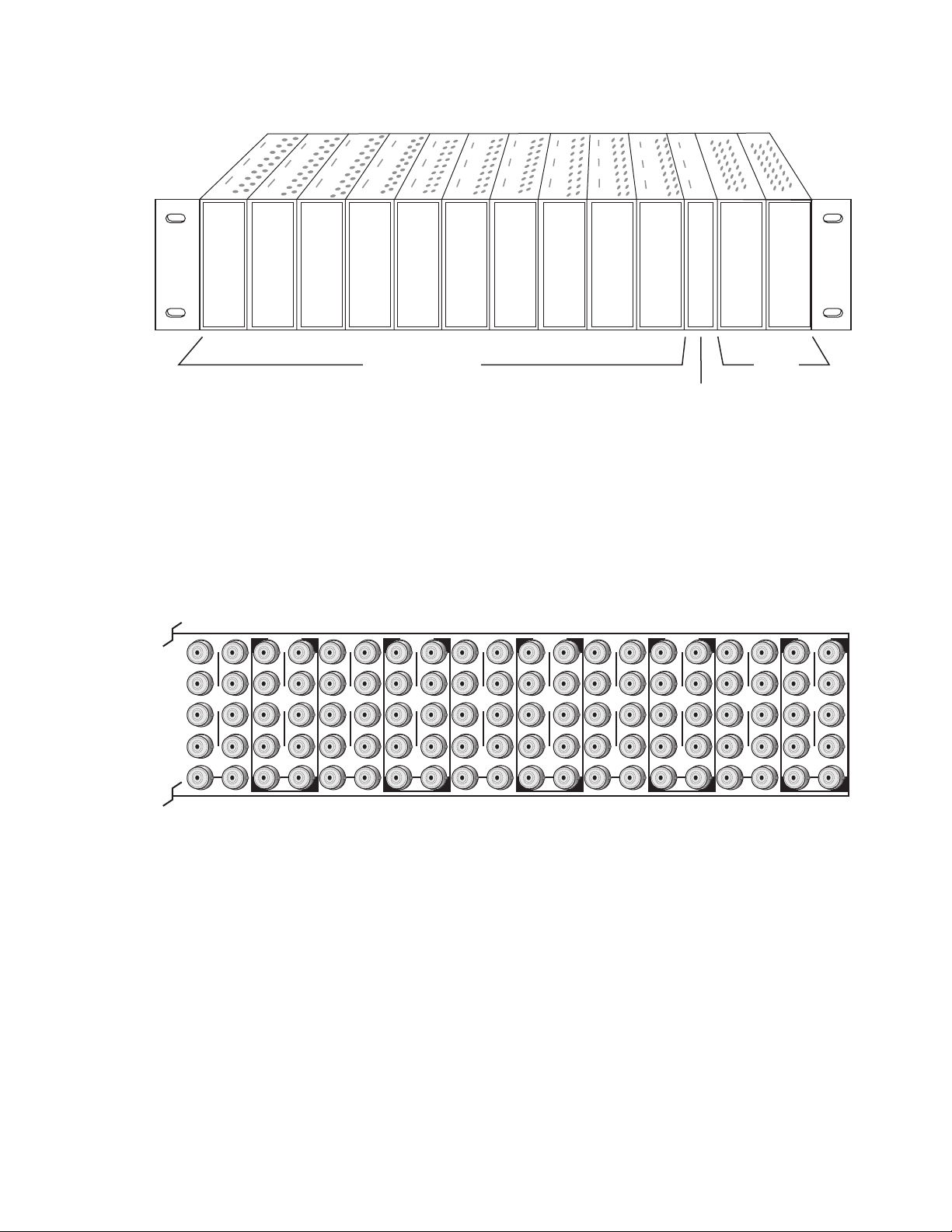
Module Placement in the Gecko 8900 Video Frame
There are ten cell locations in the video frame to accommodate either
analog or digital modules. These are the left ten locations. Refer to Figure 1
on page 9.
The two cells on the right are allocated for the power supplies. For additional information concerning the Power Supply module, refer to the 8900
Power Supply manual.
The third cell from the right is allocated for the Frame Monitor or 8900NET
Network Interface module. These modules provide health monitoring and
control options.
8 8981NR Instruction Manual
Page 9
1.
2.
3.
Figure 1. Gecko 8900 Series Frame
Installation
8226_04r0
DA10
J1 J2
O
J3 J4
U
T
J5 J6
J7 J8
J9 J10
IN
DA9
J1 J2
J2
O
J3 J4
J4
U
T
J5 J6
J6
J7 J8
J8
J9 J10
IN
Any 8900 Module
Power
Supplies
Frame Controller or
(only)
8900NET Network
Interface Module
8900 module slots are interchangeable within the frame. There are 10 BNC
connectors in each slot’s I/O group. The functional assignment of each connector in a group is determined by the module that is placed in that slot.
The maximum number of modules a Gecko 8900 frame can accept is ten.
Figure 2 illustrates the rear connector plate for a Gecko 8900 frame.
Figure 2. Gecko 8900 Series Video Frame Rear Connector
DA8
J1 J2
O
J3 J4
U
T
J5 J6
J7 J8
J9 J10
IN
DA7
J1 J2
J2
O
J3 J4
J4
U
T
J5 J6
J6
J7 J8
J8
J9 J10
IN
DA6
J1 J2
O
J3 J4
U
T
J5 J6
J7 J8
J9 J10
IN
DA5
J1 J2
J2
O
J3 J4
J4
U
T
J5 J6
J6
J7 J8
J8
J9 J10
IN
DA4
J1 J2
O
J3 J4
U
T
J5 J6
J7 J8
J9 J10
IN
DA3
J2
J1 J2
O
J4
J3 J4
U
T
J6
J5 J6
J8
J7 J8
J9 J10
IN
DA2
J1 J2
O
J3 J4
U
T
J5 J6
J7 J8
J9 J10
IN
DA1
J1 J2
O
J3 J4
U
T
J5 J6
J7 J8
J9 J10
IN
8226_03
To install a module in the frame:
Insert the module, connector end first, with the component side of the
module facing to the right and the ejector tab to the top.
Verify that the module connector seats properly against the backplane.
Press in the ejector tab to seat the module.
8981NR Instruction Manual 9
Page 10
Installation
Cabling
Cabling to and from the module is done at the back of the Gecko 8900
frame.
Inputs
Outputs
Note
At the back of every hard cover manual are overlay cards that can be placed
over the rear connector BNCs to identify the specific 8981NR connector functions.
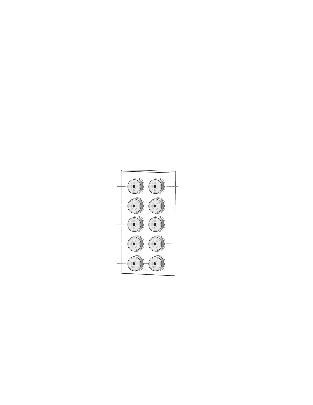
One SDI input is provided at BNC J7. Line rate is indicated by 525 or 625
Present LED (Figure 4 on page 11).
Four serial digital video outputs are provided at BNCs J1, J2, J3, and J4 as
shown in Figure 3.
Figure 3. 8981NR Input/Output Connectors
X
Video Out 1
Video Out 2
J1
J3
J2
J4
J2
J4
Video Out 3
Video Out 4
Not Used
Video In
Not Used
J5
J7
J9 J10
J6
J8
J6
J8
Not Used
Not Used
Not Used
8226_02
10 8981NR Instruction Manual
Page 11
Power Up
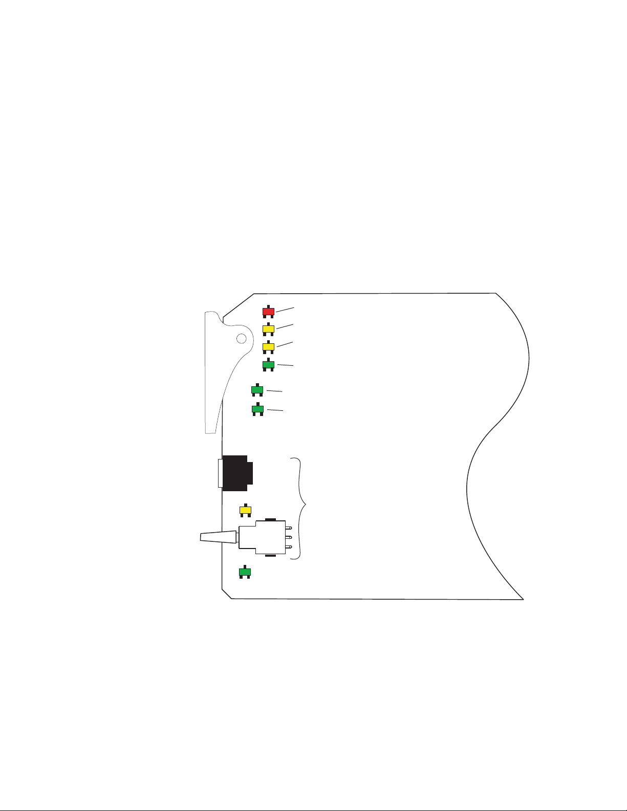
Operation Indicator LEDs
Power Up
The front LED indicators and configuration switches are illustrated in
Figure 4. Upon power-up, the green PWR LED should light and the yellow
CONF LED should illuminate for a few seconds for the duration of module
initialization.
With factory default configuration and a valid input signal connected, the
green PWR LED and one of the green signal standard LEDs (525 or 625)
should illuminate (refer to Table 2 on page 12 to see the possible operating
indicator combinations).
Figure 4. LEDs and Configuration Switches
525 625
PRESENT
INPUT
FUNCTION
2ND
UP
DOWN
DELAY
FAULT
COMM CONF PWR
2ND LED
FAULT – Red LED is off during normal operation.
COMM – Yellow LED on indicates frame bus traffic.
CONF – Yellow LED on indicates module is initiating,
changing operating mode, or updating firmware.
PWR – Green LED on indicates power OK.
525 – Green LED on indicates 525 input present.
625 – Green LED on indicates 625 input present.
Module Configuration Switches and LEDs.
8226_05
8981NR Instruction Manual 11
Page 12

Power Up
Table 2. Board Edge LED Names and Meaning
LED Indication Condition
Off Normal operation.
FAULT
(red)
COMM
(yellow)
CONF
(yellow)
PWR
(green)
525
(green)
625
(green)
2ND
(yellow)
DELAY
(green)
On continuously Module has detected an internal fault. (Refer to Service on page 35.)
Flashing Configuration problems. Check inputs and settings. Missing video.
Off No activity on frame communication bus.
3 Quick Pulses Locate Module command received by the module from a remote control system.
Short flash Activity present on the frame communication bus.
Off Module is in normal operating mode.
On continuously Module is initializing, changing operating modes or updating firmware.
3 Quick Pulses Locate Module command received by the module from a remote control system.
Off No power to module or module’s DC/DC converter failed.
On continuously Normal operation, module is powered.
Off Input signal standard is other than 525.
On continuously Valid 525 video signal is present
Off Input signal standard is other than 625.
On continuously Valid 625 video signal is present
Off Rotary switch is addressing Bank 1 configuration functions
On continuously Rotary switch is addressing Bank 2 configuration functions
Off
On continuously
Not Used
12 8981NR Instruction Manual
Page 13

Configuration
The 8981NR can be configured locally using onboard switches or remotely
using the 8900NET network interface GUI or a networked control panel.
Refer to the following sections for configuration instructions:
•Configuration Summary (page 13)
• Local Onboard Module Configuration (page 17)
•Remote Control and Monitoring (page 20)
•Control Panel Configuration (page 33)
Operation of these control types is explained in detail in their respective
sections of this manual.
Configuration
Configuration Summary
This section provides a summary of all parameters that can be configured
on the 8981NR module. Table 3 on page 16 provides a summary in table
format of all parameters and their ranges, default values, and remote, local,
and control panel function names and locations for setting each value.
Noise Filter Controls
Noise controls for two different noise reduction methods—recursive and
median— targeted at different sources of noise, are provided on the
module.
Recursive Filter
Recursive filtering is effective for low levels of wide-band (random) noise
that have no frame-to-frame correlation. In this method of filtering, the
input video data is mixed with a portion of the recursive filter output that
is delayed by exactly one frame only if its value is with an adjustable noise
threshold level of that output. The portion amount is set by the recursion
coefficient from none to 100% (an output freeze).
When recursive filtering is enabled, two controls become available:
•Noise Threshold Level – adjustment should be made just slightly
higher than the peak noise level.
•Noise Coefficient – adjustment should be made for minimum acceptable noise suppression.
Both of these adjustments should be set as low as acceptable to minimize
motion blurring artifacts.
8981NR Instruction Manual 13
Page 14

Configuration
Median Filter
This filtering method acts to replace individual pixels with one of its neighboring pixels in the horizontal direction if it is not with the value range of
the nearest neighboring pixels. This type of filtering is very effective for
single pixel impulse noise where there is no horizontal (line) picture correlation.
The median filter is enabled with an On/Off control. This type of filter has
a larger peak level than the random noise so it occurs before the recursive
filter.
If no impulse noise is present in the signal, it is recommended to leave the
median filter in the Off position, as high frequency horizontal resolution
(sharpness) is reduced with its use.
Other Noise Filter Controls
The following controls are also included with the noise filtering to aid in
making noise adjustments:
Display Bar – when enabled, a sliding horizontal white bar will indicate the
relative value for noise threshold (top) and recursive coefficient (bottom)
on a black background, indicating the full-scale position.
Split Screen – when enabled, allows the output to be split for comparing the
unprocessed video data on the right to the processed video on the left.
Random Noise Generator – when enabled, pseudo-random, wide-band
noise with no average DC value at a peak level of about 8 IRE will be added
to the input. This level is at a practical limit for using recursive filtering and
can be used for experimenting with the noise threshold and recursion coefficient controls. Most actual noise sources will be lower than with this generator and will require lower settings.
Impulse Noise Generator – when enabled, and the random noise generator
is also enabled, positive, single pixel impulse of about 50 IRE are added to
the noise generator output. This control is useful for testing the median
filter.
Note
When the module is powered down, upon restart the Display Bar, Split
Screen, Random Noise Generator, and Impulse Noise Generator will be disabled and must be re-enabled using the local or remote controls.
14 8981NR Instruction Manual
Page 15

Proc Amp Controls
When the video processor is enabled, the following independent adjustments can be made to the SDI video signal:
•Y, B-Y, and R-Y offset, and
•Y, B-Y, and R-Y gains.
When the Gain Lock control is enabled, all three channels will change gain
by the same amount when any of the channel’s gain settings are adjusted.
When disabled, all processing is bypassed and when re-enabled, the previous settings are in effect.
Vertical Ancillary Line Controls
The module provides controls for blanking all vertical ancillary data (Yes
or No in remote or VANC Pass or VANC Blank in local mode). When
blanking is enabled on all lines, in 525 mode only, the blanking width can
be set to line 20 or line 21 (blank line 21 – Yes or No in remote or set blanking
width to line 20 or line 21 in local mode).
Configuration
All horizontal interval data is passed to the output without processing.
Recall or Save Settings
The current module settings can be saved or recalled into/from one of four
memory registers. All controls, except the test modes, will be stored.
8981NR Instruction Manual 15
Page 16

Configuration
Table 3 provides a complete summary of the 8981NR processing functions
and a comparison of the functionality available with each control type
along with the ranges and default values for each parameter.
Table 3. Summary of 8981NR Configuration Functions
Control
Function
Type
Recursive filter On On/Off
Noise threshold 50.2%
Noise recursion coefficient 75%
Median filter Off On/Off
Display bar Off On/Off
Split screen Off On/Off
Random noise generator Off On/Off
Impulse noise generator Off On/Off
Video proc amp Off On/Off
Y offset 0%
B-Y offset 0%
R-Y offset 0%
Y gain 100%
B-Y gain 100%
R-Y gain 100%
Gain lock On On/Off
Blank all vertical ancillary
lines
Set blanking width in 525
Save/Recall Registers 1–4 N/A Registers 1–4
Default
Blank to
line 20
Range/Choices
Resolution
0–100%
(0.4% steps)
0–100%
(0.8% steps)
–3.5 to 3.4%
(0.11% steps)
–3.5 to 3.4%
(0.11% steps)
–3.5 to 3.4%
(0.11% steps)
59.4 to 140.6%
(0.4% steps)
59.4 to 140.6%
(0.4% steps)
59.4 to 140.6%
(0.4% steps)
No Yes/No
Blank to line 20
Blank to line 21
Web Page/
Function Name
Noise Filters/
Recursive Filter On/Off pulldown
Noise Filters/
Noise Threshold (%)
Noise Filters/
Coefficient (%)
Noise Filters/
Median Filter On/Off pulldown
Noise Filters/
Display Bar pulldown
Noise Filters/
Split Screen pulldown
Noise Filters/
Random Noise Gen pulldown
Noise Filters/
Impulse Noise Gen pulldown
Proc Amp/
On/Off pulldown
Proc Amp/
Y Offset (%)
Proc Amp/
B-Y Offset (%)
Proc Amp/
R-Y Offset (%)
Proc Amp/
Y Gain (%)
Proc Amp/
B-Y Gain (%)
Proc Amp/
R-Y Gain (%)
Proc Amp/
Gain Lock pulldown
Vertical Ancillary Lines/
Blank All Lines pulldown
Blank Line 21 pulldown 2:D (Line 20 or 21) Blank21
Recall or Save Settings/
Save Register #
Recall or Save Settings/
Recall Register #
Rotary Switch
Bank/Setting
2:3 RecrFilt
2:1 NoisThrh
2:2 Coefient
2:4 MediFilt –
1:1 DispBar –
1:2 SplitScr –
1:3 RanNsGen –
1:4 ImpNsGen
2:5 ProcAmp
2:6 Y Offset
2:7 B-Y Ofst
2:8 R-Y Ofst
2:9 Y Gain
2:A B-Y Gain
2:B R-Y Gain
2:C N/A
2:E (Blank or Pass) BlankAll
1:A
(Save/Recall Reg 1)
1:B
(Save/Recall Reg 2)
1:C
(Save/Recall Reg 3)
1:D
(Save/Recall Reg 4)
Control
Panel
Mnemonic
N/A –
Notes/
Conditions
Recursive filter
enabled
Random noise
gen must be on
Video Proc
enabled
Locks all gain
controls
Blank all must
be yes
16 8981NR Instruction Manual
Page 17

Local Onboard Module Configuration
The 8981NR module can be configured locally using the rotary and paddle
switches. Several LEDs interact with the switches to indicate status of the
configuration process.
Configuration Switches and Controls
Refer to Figure 5 for the following descriptions. Use the onboard configuration components as follows:
• Function (rotary) switch – this switch accesses a desired function for
configuration (see Table 4 on page 19). The switch addresses two banks
of functions; each bank has 16 possible positions (0 through 9 and A
through F). Not all positions are used.
The next bank of functions is accessed each time the Function switch
makes a complete revolution past zero (or back through F): While in
Bank 1, a complete revolution past zero accesses Bank 2; while in Bank
2, a complete revolution past zero accesses Bank 1 again. The yellow
2ND LED indicates which bank is currently being accessed.
Configuration
Note
•2ND (second Function) yellow LED – when off, indicates that the rotary
• Paddle switch – actuates or selects the desired setting for the selected
• CONF (configuring) yellow LED – when on, indicates the module is ini-
• Jumper JP5 allows or locks out (Local) remote control.
Figure 5. Module Configuration Switches and LEDs
JP5
Remote Lockout
JP5
CONF LED
Function rotary switch
2ND Function LED
Paddle switch
The Function switch should be kept in position 0 in any bank (parked) when
not in use to avoid any inadvertent change in configuration. Position 0 in each
bank is inactive.
switch is addressing the first bank of functions. When on, indicates that
the rotary switch is addressing the second bank of functions.
function when the switch is held momentarily in either the up or down
position.
tializing or processing configuration information.
LOCAL (1–2)
LCL&REM (2–3)
Place jumper in Local position
to lock out remote access.
8981NR Instruction Manual 17
8226_08
Page 18

Configuration
8981NR Module Onboard Configuration Settings
To make a configuration setting:
Rotate the Function switch to Bank 1 (2ND LED off) or Bank 2
(2ND LED on), then to the desired function within that bank.
Move the paddle switch to the up or down position and hold
momentarily to set the desired function (refer to Table 4).
1.
2.
Note
3.
Holding the paddle switch in the up or down position for more than a half
second will automatically accelerate through the value range for parameters
with 256 or more values. The full range can be accessed in about 10 seconds.
Refer to
function. Table 3 on page 16 also gives a summary of value ranges, step
sizes, default values, etc. for each function
Configuration Summary
on page 13 for an overview of each
18 8981NR Instruction Manual
Page 19

Table 4. Local Rotary and Paddle Switch Functions
Configuration
Function
Switch
Setting
Bank 1 (2ND LED off)
0– –Default position for normal operation (parked)
1On Off Turn display bar on or off
2On Off Turn split screen on or off
3On Off Turn random noise generator on or off
4On Off Turn impulse noise generator on or off
5-9 Not used
A Recall Register 1 Save Register 1 Save or recall settings to Register 1
B Recall Register 2 Save Register 2 Save or recall settings to Register 2
Bank 1 (2ND LED off)
C Recall Register 3 Save Register 3 Save or recall settings to Register 3
D Recall Register 1 Save Register 1 Save or recall settings to Register 1
E Recall factory defaults – Recall defaults from Table 3 on page 16
F Not used
Bank 2 (2ND LED on)
0– –Default position for normal operation (parked)
1 Increase Decrease Adjust noise threshold setting (%)
2 Increase Decrease Adjust noise recursion coefficient (%)
3On Off Turn recursive filter on or off
4On Off Turn median filter on or off
5On Off Turn video proc amp on or off
6 Increase Decrease Adjust Y offset
7 Increase Decrease Adjust B-Y offset
8 Increase Decrease Adjust R-Y offset
9 Increase Decrease Adjust Y gain
Bank 2 (2ND LED on)
A Increase Decrease Adjust B-Y gain
B Increase Decrease Adjust R-Y gain
COn Off Turn video gain lock on or off
D Blank to 20 Blank to 21 Set blanking width to line 20 or line 21 in 525
EVANC pass VANC blank Pass or blank all vertical ancillary data
F Not used
Paddle
Switch Up
Paddle
Switch Down
Function Description
8981NR Instruction Manual 19
Page 20

Configuration
Remote Configuration and Monitoring
8981NR configuration and monitoring can be performed using a web
browser GUI interface when the 8900NET Network Interface module is
present in the frame (Gecko 8900TFN frame). This section describes the
GUI access to the module configuration functions.
For remote access, make sure the jumper block on the module is set for both
Local and Remote access (Figure 5 on page 17).
Refer to the
mation on the 8900NET Network Interface module and setting up and
operating the Gecko 8900 frame network.
Refer to the Frame Status page shown in Figure 6 on page 21. The 8900
modules can be addressed by clicking either on a specific module icon in
the frame status display or on a module name or slot number in the link list
on the left.
Note
Use the
ware version 3.0 and later).
The
Online Manual Link
pdf format. Link configuration is done on the Frame Configuration page.
For information on status and fault monitoring and reporting shown on the
Status page, refer to
8900NET Network Interface Module Instruction Manual
The physical appearance of the menu displays on the web pages shown in
this manual represent the use of a particular platform, browser and version
of 8900NET module software. They are provided for reference only. Displays
will differ depending on the type of platform and browser you are using and
the version of the 8900NET software installed in your system.
Refresh
button to update the display (available with 8900NET soft-
button can be set up to link to the documentation in
Status Monitoring on page 36.
for infor-
20 8981NR Instruction Manual
Page 21

Figure 6. Frame Status Page
8038_08
The Links section lists the frame and its current modules. The selected link's Status
page is first displayed and the sub-list of links for the selection is opened. The sub-list
allows you to select a particular information page for the selected device.
Content display section displays the information page
for the selected frame or module (frame slot icons are also
active links).
Online Manual Link
Refresh button for manual
update of page
Configuration
8981NR Instruction Manual 21
Page 22

Configuration
8981NR Links and Web Pages
The 8900 GUI provides the following links and web pages for the 8981NR
module (Figure 7):
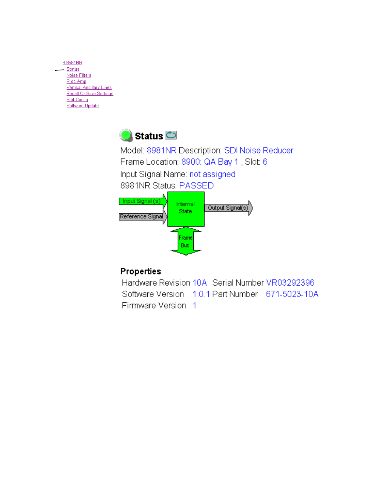
• Status – reports input and reference signal status and module information (page 23),
•Noise Filters – turn on recursive and median noise filters and
enable/disable Display Bar, Split Screen, Random Noise Generator and
Impulse Noise Generator (page 24),
•Proc Amp – enable or disable Proc Amp and make video processing
adjustments (page 26),
•Vertical Ancillary Lines – select to pass or blank vertical ancillary lines
(page 28),
•Recall or Save Settings – save or recall module settings to registers
(page 29),
• Slot Config – provides a Locate Module function and Slot Memory
(page 30), and
• Software Update – allows updating of software (page 32).
Figure 7. 8981NR Web Page Links
22 8981NR Instruction Manual
Page 23
Status Page
Configuration
Use
this
link
The Status page (Figure 8) shows the status of the input signal. Color
coding of the display indicated the signal status. Refer to Status Monitoring
on page 36 for an explanation of the color coding.
Information about the module, such as part number, serial number, hardware revision and software and firmware versions are given in a read-only
section at the bottom of the display.
Figure 8. 8981NR Status Page
8981NR Instruction Manual 23
Page 24

Configuration
Use
this
link
Noise Filters
The Noise Filters page (Figure 9 on page 25) provides the controls for
turning on and adjusting noise filtering and enabling the display bar and
split screen and the impulse and random noise generators.
Refer to Configuration Summary on page 13 for an overview of each function
and when to use each filtering type. Table 3 on page 16 also gives a
summary of value ranges, step sizes, default values, etc. for each function.
•
•
The following controls can be enabled for use with the noise filters:
Recursive Filter pulldown – turn recursive filtering on or off.
With recursive filtering on, the following recursive noise controls can
be set:
•
Noise Threshold – set the amount of noise threshold in percent.
•
Coefficient – set the noise recursive coefficient.
These controls will be grayed out when the Recursive Filter is off.
Median Filter pulldown – turn median filtering on or off.
•
Display Bar – enables a sliding horizontal white bar to indicate the rela-
tive value for noise threshold (top) and recursive coefficient (bottom)
on a black background.
•
Split Screen – allows the output to be split for comparing the unproc-
essed video data on the right to the processed video on the left.
•
Random Noise Generator – adds a pseudo-random, wide-band noise to the
input. Can be used for experimenting with the noise threshold and
recursion coefficient controls. Most actual noise sources will be lower
than with this generator and will require lower settings.
•
Impulse Noise Generator – adds a positive, single pixel impulse to the noise
generator output. The random noise generator must also be enabled.
Useful for testing the median filter.
24 8981NR Instruction Manual
Page 25
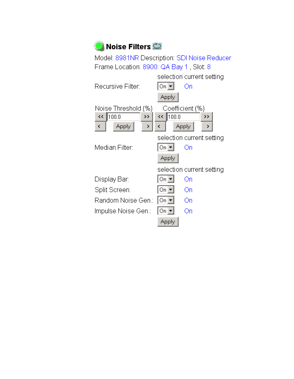
Figure 9. 8981NR Noise Filters Page
Configuration
8981NR Instruction Manual 25
Page 26

Configuration
Use
this
link
Proc Amp Page
The Proc Amp page (Figure 10 on page 27) provides access to processing
amplifier controls. Refer to Table 3 on page 16 for a summary of controls,
defaults, parameter ranges and what lines of video are affected by each
control.
•Proc Amp– enable or disable (On/Off) processing amplifier for the SDI
signal.
When the Proc Amp is enabled, the following controls will be active:
•Y Gain – adjusts the percentage of luminance relative to white.
• B-Y Gain – adjusts the percentage of B-Y gain.
•R-Y Gain – adjusts the percentage of R-Y gain.
Set the
with any of the gain controls above.
•Y Offset – adjusts percentage of Y offset.
• B-Y Offset – adjusts percentage of B-Y offset.
•R-Y Offset – adjusts percentage of R-Y offset.
Gain Lock control to On to adjust the gain of all three channels together
26 8981NR Instruction Manual
Page 27

Figure 10. 8981NR Proc Amp Page
Configuration
8981NR Instruction Manual 27
Page 28

Configuration
Use
this
link
Vertical Ancillary Lines Page
Use the Vertical Ancillary Lines page (Figure 11) to set the module for the
following functions:
•
Blank All Lines – set to No to pass all lines or blank all lines (Yes).
•
Blank Line 21 – In 525 mode, when vertical ancillary lines are blanked, set
to Yes to blank or No to pass line 21.
Figure 11. 8981NR VBI Page in 525 Line Rate
28 8981NR Instruction Manual
Page 29

Use
this
link
Recall or Save Settings Page
Four storage registers are accessible on the module for saving and recalling
module settings. Enter a register number or use the arrow buttons to bring
up a specific register.
• Set up the desired module parameters and enter a register number (1-4)
in the
Select the
ration.
Save Register # field to store the setup and select the Apply button.
Store User Settings button to save the current module configu-
Configuration
•Recall the register by entering the number (1-4) in the
field and selecting the Apply button then the Restore User Settings button.
•
Recall Fact Defaults – select this button to recall the factory defaults listed
in Table 3 on page 16.
Figure 12. 8981NR Timing with Line Sync
Recall Register #
8981NR Instruction Manual 29
Page 30

Configuration
Use
this
link
Slot Config Page
Use the Slot Config page (Figure 13 on page 31) to perform the following
functions on the 8981NR module:
•
Locate Module – selecting the On pulldown flashes the yellow COMM
and CONF LEDs on the front of the module so it can be located in the
frame.
•
Slot Identification – You may identify the module by typing a specific
name in the
module and travels with the 8900NET module if it is moved to another
frame. Select
•
Slot Memory – the slot configuration for each media module is automati-
cally saved periodically (once an hour) to the 8900NET module in that
frame. You may also select the
save the current configuration for this slot. The configuration is saved
on the 8900NET module. If the 8900NET module is removed or
powered down, the stored configurations are not saved.
Name field. The assigned name is stored on the 8900NET
Default to enter the factory default module name.
Learn Module Config button at any time to
When the
ration saved to this slot is saved as slot memory. When the current
module is removed and another module of the same type is installed,
the configuration saved to the 8900NET module will be downloaded to
the new module. The box must be checked before the current module
with the saved configuration is removed.
•
Hardware Switch Controls – a read-only status report of 8900NET module
switch settings for Module Status Reporting and Asynchronous Status
Reporting. These functions must be enabled for the following Slot
SNMP Trap Reports to function.
•
Slot SNMP Trap Reports – displayed only when the SNMP Agent software
has been installed on the 8900NET module. Slot SNMP traps can be
enabled only when the hardware switches for Module Fault reporting
and Asynchronous Status reporting are in enabled on the 8900NET
module (dipswitch S1 segment 7 and dipswitch S2 segment 1).
The enabled SNMP traps will be reported to any SNMP manager that
is identified as an SNMP Report Destination in 8900NET configuration.
Trap severity is read-only hard-coded information that is interpreted
and responded to by the SNMP Manager software configuration.
SNMP reporting can be also be disabled for individual signal inputs on
the I/O Config and Video Composite In web pages.
Restore upon Install box has been checked, the current configu-
30 8981NR Instruction Manual
Page 31

Figure 13. 8981NR Slot Config Page
Configuration
8981NR Instruction Manual 31
Page 32

Configuration
Use
this
link
Software Update Page
The Software Update page (Figure 14) allows updating of software from
remote locations such as a CD-ROM or the Grass Valley web site. For
instructions on updating to the latest software, refer first to the 8981NR
Release Notes that accompany the software update for compete details.
Software updates may also be performed using the NetConfig application
available from Grass Valley. Refer to the NetConfig Instruction Manual for
more information.
Figure 14. 8981NR Software Update Page
32 8981NR Instruction Manual
Page 33

Control Panel Configuration
An external control panel is available to interface over the network to the
8981NR module. The configuration functions available with the Grass
Valley Newton Control System are summarized in Table 3 on page 16. In
addition, the control panel mnemonics that will appear with each available
function are given in the table.
Note Not all configuration parameters may be available with the control panel.
Installation, configuration, and operation of the Newton Modular Control
System is provided in a separate manual provided with option.
Configuration
8981NR Instruction Manual 33
Page 34

Specifications
Specifications
SDI Input
Number of inputs One, BNC
Signal type SMPTE 259M serial 10-bit 4:2:2 component video
Input impedance 75 Ω terminating
Return loss > 15 dB up to 270 MHz
SDI Outputs
Number of outputs 4, BNC
Signal type SMPTE259M 10-bit 4 2:2 component video
Output impedance 75 Ω
Return loss > 15 dB, 5 to 270 MHz
Error checking EDH embedded
Delay through module 2.8 µs
Environmental
Frame temperature range 0 to 45 degrees C
Operating humidity range 0 to 90% non-condensing
Non-operating temperature -10 to 70 degrees C
Mechanical
Frame type Gecko 8900 Video
Power Requirements
Supply voltage +12V
Power consumption < 4.5 W (2 A slow blow fuse)
Table 5. 8981NR Specifications
Parameter Value
34 8981NR Instruction Manual
Page 35
Service
Service
The 8981NR modules make extensive use of surface-mount technology and
programmed parts to achieve compact size and adherence to demanding
technical specifications. Circuit modules should not be serviced in the field
unless directed otherwise by Customer Service.
If your module is not operating correctly, proceed as follows:
•Check frame and module power and signal present LEDs.
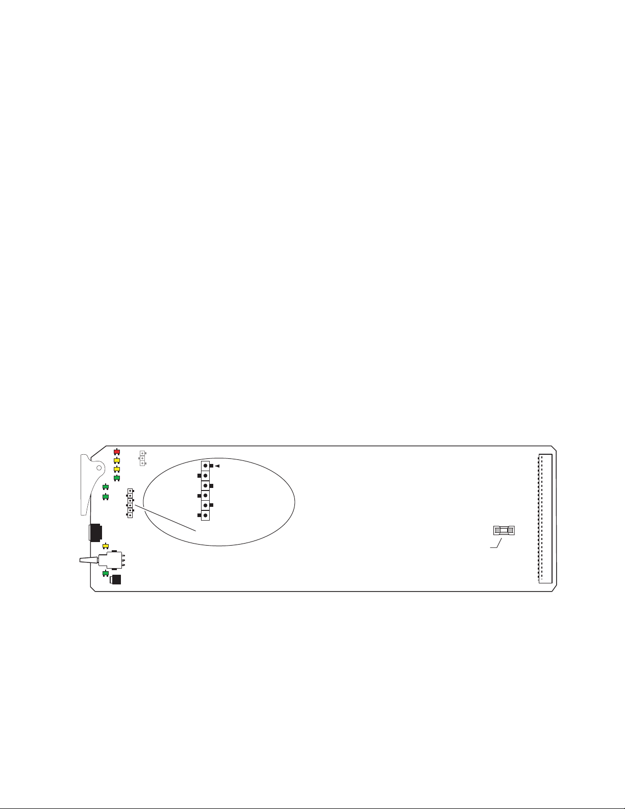
•Verify power at the voltage testpoints (see Figure 15) and check Fuse F1
if no voltage is detected.
•Check for presence and quality of input signals.
•Verify that source equipment is operating correctly.
•Check cable connections.
Refer to Figure 4 for the location of PWR LED and Table 2 on page 12 for
proper LED indications.
If the module is still not operating correctly, replace it with a known good
spare and return the faulty module to a designated Grass Valley repair
depot. Call your Grass Valley representative for depot location.
Refer to the Contacting Grass Valley at the front of this document for the
Grass Valley Customer Service Information number.
Figure 15. 8981NR Fuse and Voltage Testpoint Locations
3V
Voltage Testpoints
-5V
+5V
125 V
F2A 125V
F1
JP6
TEST
POINTS
Fuse: 2 A Slow
8226_08
8981NR Instruction Manual 35
Page 36

Status Monitoring
Status Monitoring
This section provides a summary of status monitoring and reporting for a
Gecko 8900 Series system. It also summarizes what status items are
reported and how to enable/disable reporting of each item. There are a
number of ways to monitor status of modules, power supplies, fans and
other status items depending on the method of monitoring being used.
8900 Frame status will report the following items:
• Power supply health,
• Status of fans in the frame front cover,
•Temperature,
•Module health, and
• Frame bus status.
Module health status will report the following items:
• Internal module state (and state of submodule or options enabled)
including configuration errors (warning), internal faults, and normal
operation (Pass).
LEDs
• Signal input states including valid/present (pass), not present or
invalid (warning), not monitored, and not available (no signal inputs).
•Reference input states including locked/valid (pass), not
locked/invalid (warning), and not monitored.
• Signal output states with reporting functionality (reference output).
LEDs on modules in the frame and on the front of the 8900TF/TFN frames
indicate status of the frame and the installed power supplies, fans in the
front covers, and modules. (The 8900TX-V/A frames have no LED indicators on the front cover.)
When a red FAULT LED is lit on a frame front cover, the fault will also be
reported on the 8900NET or Frame Monitor module. The LEDs on the front
of these modules can then be read to determine the following fault conditions:
• Power Supply 1 and 2 health,
• Fan rotation status,
• Frame over-temperature condition,
• Frame Bus fault (8900NET only), and
•Module health bus.
36 8981NR Instruction Manual
Page 37

Frame Alarm
Status Monitoring
In general, LED colors used on the frame and modules indicate:
•Green = normal operation, (Pass) or signal present, module locked.
•Red – On continuously = fault condition, flashing = configuration error.
•Yellow – On continuously = active condition (configuration mode or
communication), flashing in sequence = module locator function.
Status LEDs for this module are described in Operation Indicator LEDs on
page 11. LEDs for the 8900NET module are described in the 8900NET
Network Interface Instruction Manual.
A Frame Alarm connection is available on pins 8 and 9 of the RS-232 connector on the rear of 8900 frame (Frame Monitor or 8900NET Network
Interface module required). This will report any of the status items enabled
with the 8900NET or Frame Monitor module configuration DIP switch.
Connection and use of the Frame Alarm is covered in detail in the 8900NET
Network Interface Instruction Manual.
Web Browser Interface
When the 8900NET module is installed in the frame, a web browser GUI
can indicate frame and module status on the following web pages:
• Frame Status page – reports overall frame and module status in graph-
ical and text formats.
•Module Status page – shows specific input and reference signal status
to the module along with enabled options and module versions.
•A Status LED icon on each web page to report communication status
for the frame slot and acts as a link to the Status page where warnings
and faults are displayed (8900NET version 3.0 or later).
In general, graphics and text colors used indicate the following:
•Green = Pass – signal or reference present, no problems detected.
•Red = Fault – fault condition.
•Yellow = Warning – signal is absent, has errors, or is mis-configured.
•Gray = Not monitored (older 8900 module).
•White = Not present.
Status reporting for the frame is enabled or disabled with the configuration
DIP switches on the 8900NET module. Most module status reporting items
can be enabled or disabled on individual configuration web pages.
8981NR Instruction Manual 37
Page 38

Status Monitoring
SNMP Reporting
The Gecko 8900 Series system uses the Simple Network Monitoring Protocol (SNMP) internet standard for reporting status information to remote
monitoring stations. When SNMP Agent software is installed on the
8900NET module, enabled status reports are sent to an SNMP Manager
such as the Grass Valley’s NetCentral application.
There are both hardware and software report enable switches for each
report. Both must be enabled for the report to be sent. Software report
switches are set on the 8900NET Configuration page for the Frame, the
8900NET module, and each module slot. Refer to the 8900NET Network
Interface Instruction Manual for installation instructions.
38 8981NR Instruction Manual
Page 39

Index
Numerics
2ND LED 12, 17
8900 frame
frame alarm
module capacity 8
status reporting 36
8900NET module
installation
8981NR
features
B
backplane 9
C
cabling
inputs
outputs 10
COMM LED 12
CONF LED 12, 17
configuration
Local, onboard
overview 13
Remote, GUI 20
summary table 16
connectors 9
control panel
configuration
mneumonics 16
controller module 8
10
7
8
37
33
17
web site 2
E
enable SNMP 38
environmental 34
F
factory defaults 11
summary table 16
FAQ database 2
FAULT LED
states
12
troubleshooting 36
Frame Controller module 8
Frame Status page 37
frequently asked questions 2
Function rotary switch
accessing banks
settings table 19
fuse 35
17
G
gain lock
overview
remote control 26
Gecko frame 8, 34
graphical user interface (GUI) 22
Grass Valley
website
15
2
D
display bar
definition and uses
local control 19
remote control 24
summary 16
documentation online 20
8981NR Instruction Manual 39
14
I
impulse noise generator
definition and uses
local control 19
remote control 24
summary 16
inputs
14
Page 40

Index
cabling 10
SDI video 10
specification 34
installation 8
L
LEDs
front edge
Names and Meanings table 12
locate module 30
11
M
median filter
local control
overview 14
remote control 24
summary 16
module
controller
installation 8
power supply 8
slots 9
module health status 36
Module Status page 37
19
8
N
NetConfig
software updating
Newton Control System
Newton Control Panel
noise coefficient
local control
overview 13
remote control 24
summary 16
Noise Filters web page 24
noise threshold
local control
overview 13
remote control 24
summary 16
19
19
32
33
O
online documentation
Online Manual Link
web site 2
Online Manual Link 20
outputs
cabling
SDI 34
serial digital 34
specification 34
overlay 10
10
20
P
power 34
power supply 8
Proc Amp web page 26
PWR LED 12
R
random noise generator
definition and uses
local control 19
remote control 24
summary 16
rear connectors 9
Recall Factory Defaults
remote control
recall or save settings
overview
Recall or Save Settings web page 29
recursive filter
local control
overview 13
remote control 24
summary 16
Refresh button 20
repair depot 35
report enable switches 38
15
19
14
29
S
save or recall settings
local controls
SDI video inputs 10
40 8981NR Instruction Manual
19
Page 41

serial digital outputs 10
Slot Config web page 30
slot memory 30
SNMP reporting
enabling
overview 38
software download from web 2
Software Update web page 32
split screen
definition and uses
local control 19
remote control 24
summary 16
status monitoring 36
Status web page 23
switches
onboard control
30
14
17
Index
T
testpoints 35
troubleshooting 35
V
vertical ancillary data
overview
remote control 28
summary 16
Vertical Ancillary Lines web page 28
video proc amp
local controls
overview 15
remote control 26
summary 16
voltage 34
voltage tespoints 35
W
15
19
web site
documentation
FAQ database 2
Grass Valley 2
software download 2
8981NR Instruction Manual 41
2
Page 42

Index
42 8981NR Instruction Manual
Page 43

Page 44

071822600
 Loading...