

Page 1

8977AP-4B/4U
DIGITAL AUDIO PROCESSING MODULES
Instruction Manual
PACKAGE VERSION 1.0.0
071852100
FEBRUARY 2007
Page 2

Affiliate with the N.V. KEMA in The Netherlands
CERTIFICATE
Certificate Number: 510040.001
The Quality System of:
Grass Valley, Inc.
400 Providence Mine Road
Nevada City, CA 95945
United States
15655 SW Greystone Ct.
Beaverton, OR 97006
United States
10 Presidential Way
3
rd
Floor, Suite 300
Woburn, MA 01801
United States
Nederland B.V.
4800 RP BREDA
The Netherlands
Weiterstadt, Germany
Brunnenweg 9
D-64331 Weiterstadt
Germany
Rennes, France
Rue du Clos Courtel
Cesson-Sevigne, Cedex
France
Technopole Brest Iroise
CS 73808
29238 Brest Cedex 3
France
17 rue du Petit Albi-BP 8244
95801 Cergy Pontoise
Cergy, France
2300 South Decker Lake Blvd.
Salt Lake City, UT 84119
United States
7140 Baymeadows Way
Suite 101
Jacksonville, FL 32256
United States
Including its implementation, meets the requirements of the standard:
ISO 9001:2000
Scope:
The design, manufacture and support of video hardware and software products and
related systems.
This Certificate is valid until: June 14, 2009
This Certificate is valid as of: August 30, 2006
Certified for the first time: June 14, 2000
H. Pierre Sallé
President
KEMA-Registered Quality
The method of operation for quality certification is defined in the KEMA General Terms
And Conditions For Quality And Environmental Management Systems Certifications.
Integral publication of this certificate is allowed.
KEMA-Registered Quality, Inc.
4377 County Line Road
Chalfont, PA 18914
Ph: (215)997-4519
Fax: (215)997-3809
CRT 001 073004
ccredited By:
ANAB
A
Page 3
8977AP-4B/4U
DIGITAL AUDIO PROCESSING MODULES
Instruction Manual
PACKAGE VERSION 1.0.0
071852100
FEBRUARY 2007
Page 4
Contacting Grass Valley
International
Support Centers
Local Support
Centers
(available
during normal
business hours)
France
24 x 7
Australia and New Zealand: +61 1300 721 495 Central/South America: +55 11 5509 3443
Middle East: +971 4 299 64 40 Near East and Africa: +800 8080 2020 or +33 1 48 25 20 20
Europe
+800 8080 2020 or +33 1 48 25 20 20
+800 8080 2020 or +33 1 48 25 20 20
Hong Kong, Taiwan, Korea, Macau: +852 2531 3058 Indian Subcontinent: +91 22 24933476
Asia
Southeast Asia/Malaysia: +603 7805 3884 Southeast Asia/Singapore: +65 6379 1313
China: +861 0660 159 450 Japan: +81 3 5484 6868
Belarus, Russia, Tadzikistan, Ukraine, Uzbekistan: +7 095 2580924 225 Switzerland: +41 1 487 80 02
S. Europe/Italy-Roma: +39 06 87 20 35 28 -Milan: +39 02 48 41 46 58 S. Europe/Spain: +34 91 512 03 50
Benelux/Belgium: +32 (0) 2 334 90 30 Benelux/Netherlands: +31 (0) 35 62 38 42 1 N. Europe: +45 45 96 88 70
Germany, Austria, Eastern Europe: +49 6150 104 444 UK, Ireland, Israel: +44 118 923 0499
Copyright © Grass Valley. All rights reserved.
This product may be covered by one or more U.S. and foreign patents.
United States/Canada
24 x 7
+1 800 547 8949 or +1 530 478 4148
Grass Valley Web Site
The www.thomsongrassvalley.com web site offers the following:
Online User Documentation — Current versions of product catalogs, brochures,
data sheets, ordering guides, planning guides, manuals, and release notes
in .pdf format can be downloaded.
FAQ Database — Solutions to problems and troubleshooting efforts can be
found by searching our Frequently Asked Questions (FAQ) database.
Software Downloads — Download software updates, drivers, and patches.
4 8977AP-4B/4U — Instruction Manual
Page 5

Contents
Preface. . . . . . . . . . . . . . . . . . . . . . . . . . . . . . . . . . . . . . . . . . . . . . . . . . . . . . . . . . . . . . . . . . . . . 7
8977AP-4B/-4U Digital Audio Processing Modules. . . . . . . . . . . . . . . . . . . . . 9
About This Manual . . . . . . . . . . . . . . . . . . . . . . . . . . . . . . . . . . . . . . . . . . . . . . . . . . . . . 7
Introduction . . . . . . . . . . . . . . . . . . . . . . . . . . . . . . . . . . . . . . . . . . . . . . . . . . . . . . . . . . . 9
Module Features . . . . . . . . . . . . . . . . . . . . . . . . . . . . . . . . . . . . . . . . . . . . . . . . . . . . . 9
Installation . . . . . . . . . . . . . . . . . . . . . . . . . . . . . . . . . . . . . . . . . . . . . . . . . . . . . . . . . . . 10
Software Requirements. . . . . . . . . . . . . . . . . . . . . . . . . . . . . . . . . . . . . . . . . . . . . . . 10
Module Placement in the GeckoFlex Frame . . . . . . . . . . . . . . . . . . . . . . . . . . . . . 10
Rear Module Installation . . . . . . . . . . . . . . . . . . . . . . . . . . . . . . . . . . . . . . . . . . . 11
8900GEN-SM Genlock Submodule Installation . . . . . . . . . . . . . . . . . . . . . . . . 12
Front Module Installation. . . . . . . . . . . . . . . . . . . . . . . . . . . . . . . . . . . . . . . . . . . 15
Cabling . . . . . . . . . . . . . . . . . . . . . . . . . . . . . . . . . . . . . . . . . . . . . . . . . . . . . . . . . . . . . . 16
Power Up . . . . . . . . . . . . . . . . . . . . . . . . . . . . . . . . . . . . . . . . . . . . . . . . . . . . . . . . . . . . 18
Operation Indicator LEDs . . . . . . . . . . . . . . . . . . . . . . . . . . . . . . . . . . . . . . . . . . . . 18
Remote Configuration . . . . . . . . . . . . . . . . . . . . . . . . . . . . . . . . . . . . . . . . . . . . . . . . . 21
8900NET Module Information. . . . . . . . . . . . . . . . . . . . . . . . . . . . . . . . . . . . . . . . . 21
Newton Control Panel Configuration . . . . . . . . . . . . . . . . . . . . . . . . . . . . . . . . . . 21
Web Browser Interface . . . . . . . . . . . . . . . . . . . . . . . . . . . . . . . . . . . . . . . . . . . . . . . 22
Web Page Operations and Functional Elements . . . . . . . . . . . . . . . . . . . . . . . . 24
Web Page Headers. . . . . . . . . . . . . . . . . . . . . . . . . . . . . . . . . . . . . . . . . . . . . . . . . 25
8977AP-4B and 8977AP-4U Links and Web Pages. . . . . . . . . . . . . . . . . . . . . . . . 26
Status Web Page. . . . . . . . . . . . . . . . . . . . . . . . . . . . . . . . . . . . . . . . . . . . . . . . . . . 28
I/O Web Page. . . . . . . . . . . . . . . . . . . . . . . . . . . . . . . . . . . . . . . . . . . . . . . . . . . . . 31
Functional View Web Page. . . . . . . . . . . . . . . . . . . . . . . . . . . . . . . . . . . . . . . . . . 33
Input Status and Settings Web Page . . . . . . . . . . . . . . . . . . . . . . . . . . . . . . . . . . 34
Delay Web Page . . . . . . . . . . . . . . . . . . . . . . . . . . . . . . . . . . . . . . . . . . . . . . . . . . . 36
Gain Web Page . . . . . . . . . . . . . . . . . . . . . . . . . . . . . . . . . . . . . . . . . . . . . . . . . . . . 38
Routing & Processing Pairs Web Page . . . . . . . . . . . . . . . . . . . . . . . . . . . . . . . . 40
Output Status and Settings Web Page . . . . . . . . . . . . . . . . . . . . . . . . . . . . . . . . 43
User Settings Web Page . . . . . . . . . . . . . . . . . . . . . . . . . . . . . . . . . . . . . . . . . . . . 46
Genlock Web Page . . . . . . . . . . . . . . . . . . . . . . . . . . . . . . . . . . . . . . . . . . . . . . . . . 49
System Config Web Page . . . . . . . . . . . . . . . . . . . . . . . . . . . . . . . . . . . . . . . . . . . 52
Slot Config Web Page . . . . . . . . . . . . . . . . . . . . . . . . . . . . . . . . . . . . . . . . . . . . . . 54
Specifications . . . . . . . . . . . . . . . . . . . . . . . . . . . . . . . . . . . . . . . . . . . . . . . . . . . . . . . . . 56
Service. . . . . . . . . . . . . . . . . . . . . . . . . . . . . . . . . . . . . . . . . . . . . . . . . . . . . . . . . . . . . . . 58
Power-up Diagnostics Failure . . . . . . . . . . . . . . . . . . . . . . . . . . . . . . . . . . . . . . . . . 58
Troubleshooting. . . . . . . . . . . . . . . . . . . . . . . . . . . . . . . . . . . . . . . . . . . . . . . . . . . . . 58
Electronic Circuit Breaker. . . . . . . . . . . . . . . . . . . . . . . . . . . . . . . . . . . . . . . . . . . 58
Table of Alarms . . . . . . . . . . . . . . . . . . . . . . . . . . . . . . . . . . . . . . . . . . . . . . . . . . . 58
Module Repair . . . . . . . . . . . . . . . . . . . . . . . . . . . . . . . . . . . . . . . . . . . . . . . . . . . . . . 59
Functional Description . . . . . . . . . . . . . . . . . . . . . . . . . . . . . . . . . . . . . . . . . . . . . . . . . 60
8977AP-4B/4U — Instruction Manual 5
Page 6

Contents
Configuration Parameters. . . . . . . . . . . . . . . . . . . . . . . . . . . . . . . . . . . . . . . . . . . . . . . 61
Index. . . . . . . . . . . . . . . . . . . . . . . . . . . . . . . . . . . . . . . . . . . . . . . . . . . . . . . . . . . . . . . . . . . . . . 65
6 8977AP-4B/4U — Instruction Manual
Page 7

Preface
About This Manual
This manual describes the features of the 8977AP module series and the
corresponding rear modules in the GeckoFlex frame. As part of this family
of modular products, it is subject to the Safety and Regulatory Compliance
infomation described in the GeckoFlex Frames Instruction Manual.
This manual also has instructions for using the 8900GEN-SM submodule.
For more detailed information, refer to the 8900GEN-SM GeckoFlex Genlock
Submodule Instruction Manual available online on the Thomson Grass Valley
web site.
When using any of the fiber optic options on any GeckoFlex module, refer
to the laser compliance information in the GeckoFlex Frames Instruction
Manual for safety information.
8977AP-4B/4U — Instruction Manual 7
Page 8

Preface
8 8977AP-4B/4U — Instruction Manual
Page 9

8977AP-4B/-4U Digital Audio Processing Modules
Introduction
Two versions of the audio processing modules are available; the 8977AP-4B
with balanced audio (with the 8900BA-R rear module) and the 8900AP-4U
with unbalanced audio (with the 8900UE-R rear module.)
The 8977AP-4B and the 8977AP-4U modules provide audio processing for
four AES audio streams for delay, gain, sample rate conversion, and
genlock timing functionality.
Module Features
The 8977AP-4B and 8977AP-4U module features include:
• Up to 4 channels of AES audio streams (balanced or unbalanced
depending on the rear module type installed),
• Input audio receiver and output driver stages to restore and drive
signals over long coaxial or paired cables,
• Passing of PCM and Non-PCM audio signals (Dolby E),
• Performing sample rate conversion of the PCM audio signals,
• Provides genlock timing for the audio input signals with the
8900GEN-SM submodule to synchronize the audio input signals at
48 kHz,
• Audio delay management (fixed and/or tracking delay),
• Audio gain ensures the tuning of the level of each channel,
• Routing channel and audio processing module performs the selection
between two channels before applying dedicated processing,
• Pair routing module determines the allocation of the outputs of each
pair, and
• Remote control and monitoring support includes a web interface, a
Newton control panel, a NetConfig management system, and SNMP
monitoring with an application such as NetCentral.
8977AP-4B/4U — Instruction Manual 9
Page 10
Installation
Installation
Software Requirements
The front and the rear modules are delivered together as a set. Two choices
are available: one for balanced audio outputs with the 8900BA-R rear
module and one for unbalanced audio with the 8900UE-R rear module.
A 8900GEN-SM genlock submodule can be installed on the front 8977AP
module to provide a frame reference timing source.
The 8977AP-4B and the 8977AP-4U front modules can be plugged in and
removed from a GeckoFlex frame with power on without disrupting operation on adjacent running modules. When power is applied to the module,
LED indicators reflect the initialization process (see Power Up on page 18).
An 8900NET module with software version 4.0.2 or later is mandatory for
configuring the 8977AP-4B and 8977AP-4U modules.
The Grass Valley NetCentral application must be running version 4.1.12.8A
or later for proper operation.
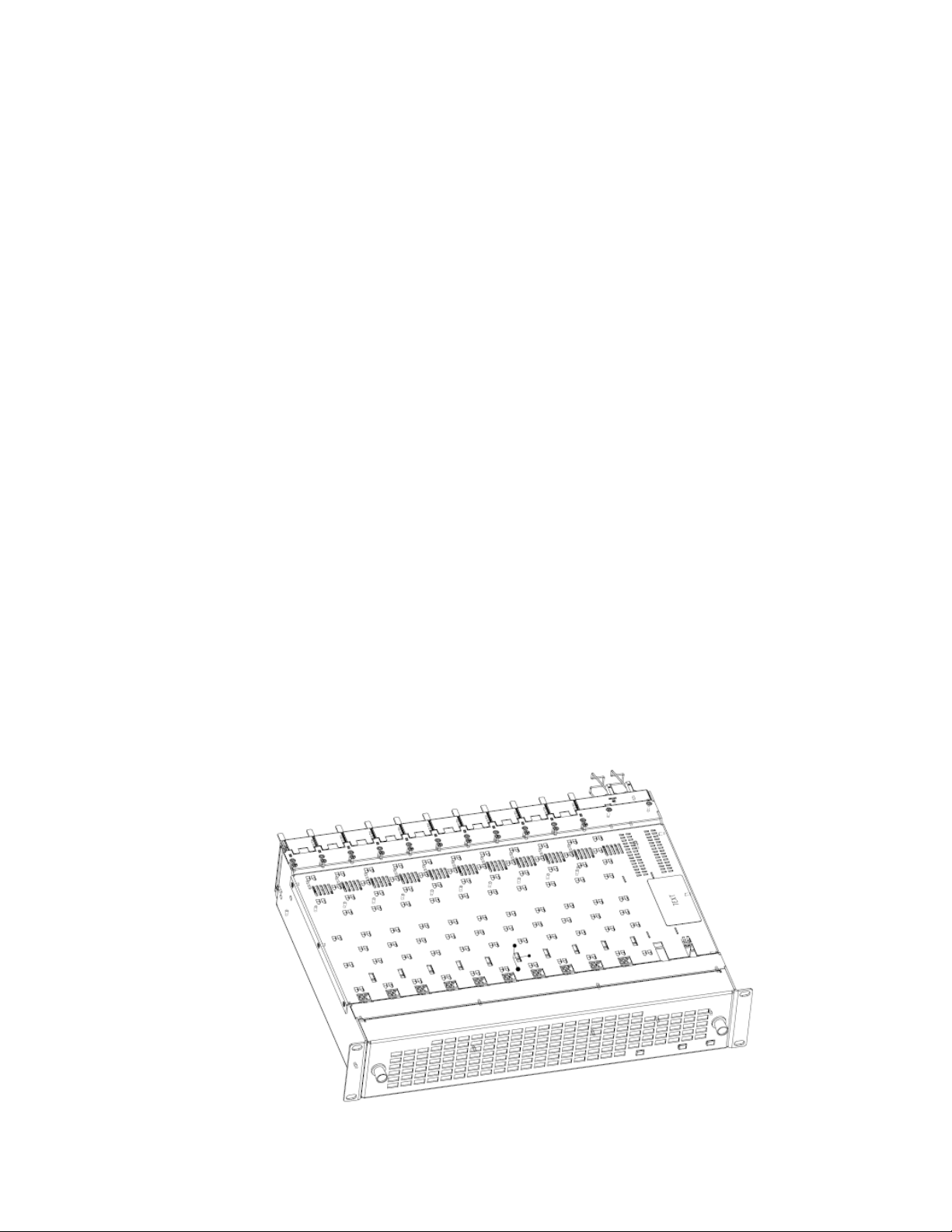
Module Placement in the GeckoFlex Frame
There are ten rear and front slot locations in the 2 RU frame to accommodate audio and video modules. The 8977AP-4B and 8977AP-4U modules
can be plugged into any one of the GeckoFlex frame slots.
Note Use standard anti-static precautions when handling modules in the frame.
Figure 1. GeckoFlex Frame
10 8977AP-4B/4U — Instruction Manual
Page 11
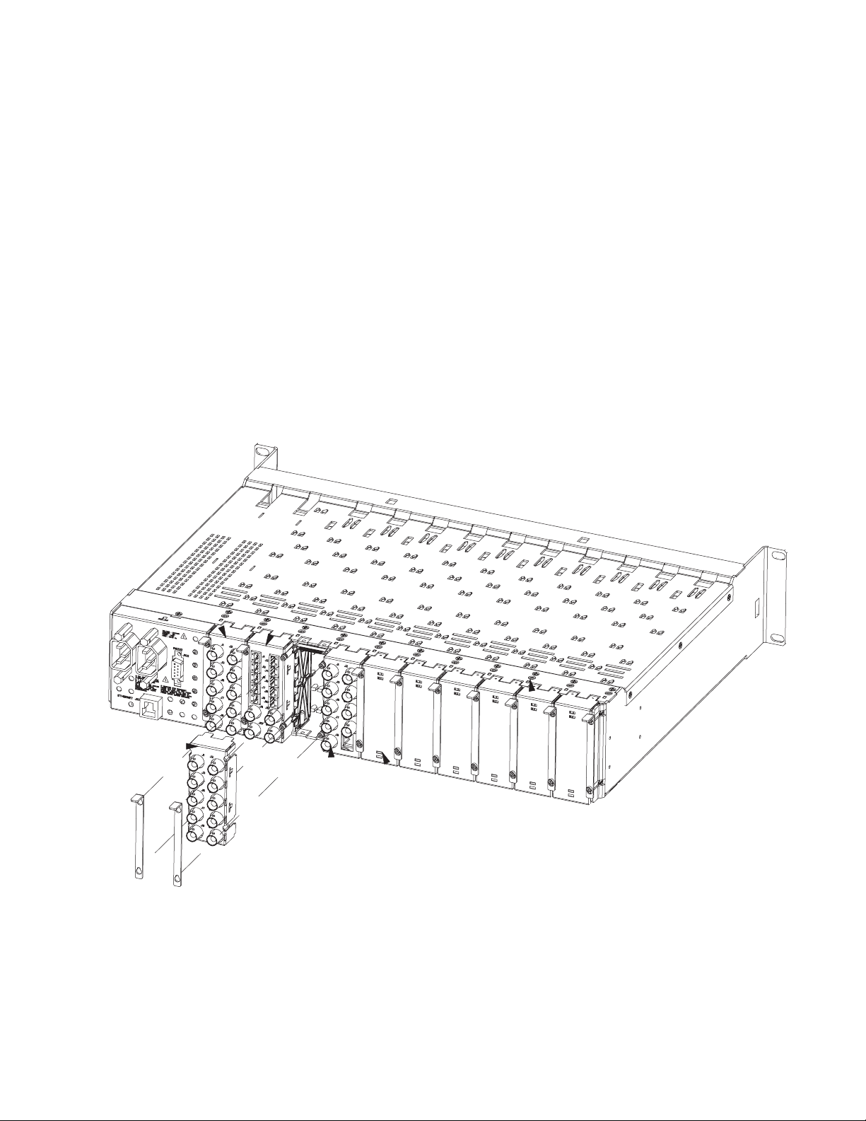
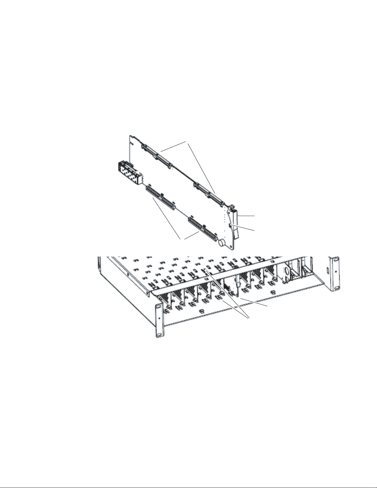
Rear Module Installation
8521_02
Note Do not completely remove the screws holding the retainer strips as they can
fall into other equipment and create a shorting hazard.
To install a rear module into the frame, follow these steps:
1. Unscrew the blank rear adapter cover (without removing the screws),
with a 2mm (5/64”) hex screwdriver (see Figure 2).
2. Remove the two retainer strips and the blank rear adapter cover using
a pair of needlenose pliers.
3. Insert the corresponding rear module in the slot.
4. Replace both retainer strips on each side of the rear module and tighten
the screws to secure the rear module.
Figure 2. Frame Rear
Installation
Note To extract the rear module, remove the front module first.
8977AP-4B/4U — Instruction Manual 11
Page 12

Installation
8900GEN-SM Genlock Submodule Installation
Conditions
Before installing the 8977AP module, you will first need to determine if and
how you want to use a genlock reference or the available frame reference
buses. The genlock timing from an 8900GEN-SM submodule can be uti
lized in several ways. Refer to 8900GEN-SM GeckoFlex Genlock Instruction
Manual available online for a complete overview of using the genlock ref
erence.
In addition to the capability of providing a local external reference to this
specific 8977AP module with an 8900GEN-SM submodule installed, slots 1
and 3 of the GeckoFlex Frame have been specifically designed to distribute
an independent frame bus reference transmitted from the 8900GEN-SM
submodule mounted on another GeckoFlex module with this capability
configured for this purpose.
If another module with a genlock submodule installed has already been
configured and installed for frame bus distribution, you may configure this
module’s output timing to lock to the Frame Bus 1 or Frame Bus 2 reference
from the other 8977AP module. In this case, the 8977AP module does not
require the use of an additional 8900GEN-SM submodule.
-
-
The use of the genlock reference is determined by the setting of the Output
Timing on the System Config web page of the module and module placement in the frame and jumper configuration as summarized below:
• Local Reference – the 8977AP with an 8900GEN-SM submodule can
have a local external reference connected to the corresponding Reference In BNC. This external timing reference will be fed to this specific
8977AP module only.
• Frame Reference 1 or 2 – when an 8977AP with an 8900GEN-SM submodule is installed in slot 1 and/or slot 3, a frame timing bus can be
enabled to distribute the external reference connected to the corresponding Reference In BNC on the rear module to all modules in the
frame that can accept a genlock reference. Slot 1 provides Frame Bus 1
and slot 3 provides Frame Bus 2.
• Internal – when no 8900GEN-SM submodule is installed on the 8977AP
module, the Output Timing can be set to Internal so the output timing
will be in an internal freerun mode (delivered by a local oscillator).
Note The internal mode is mainly implemented for test and debug purposes during
the system setup of the module or in a standalone configuration where no
timing reference is required.
12 8977AP-4B/4U — Instruction Manual
Page 13
Installation
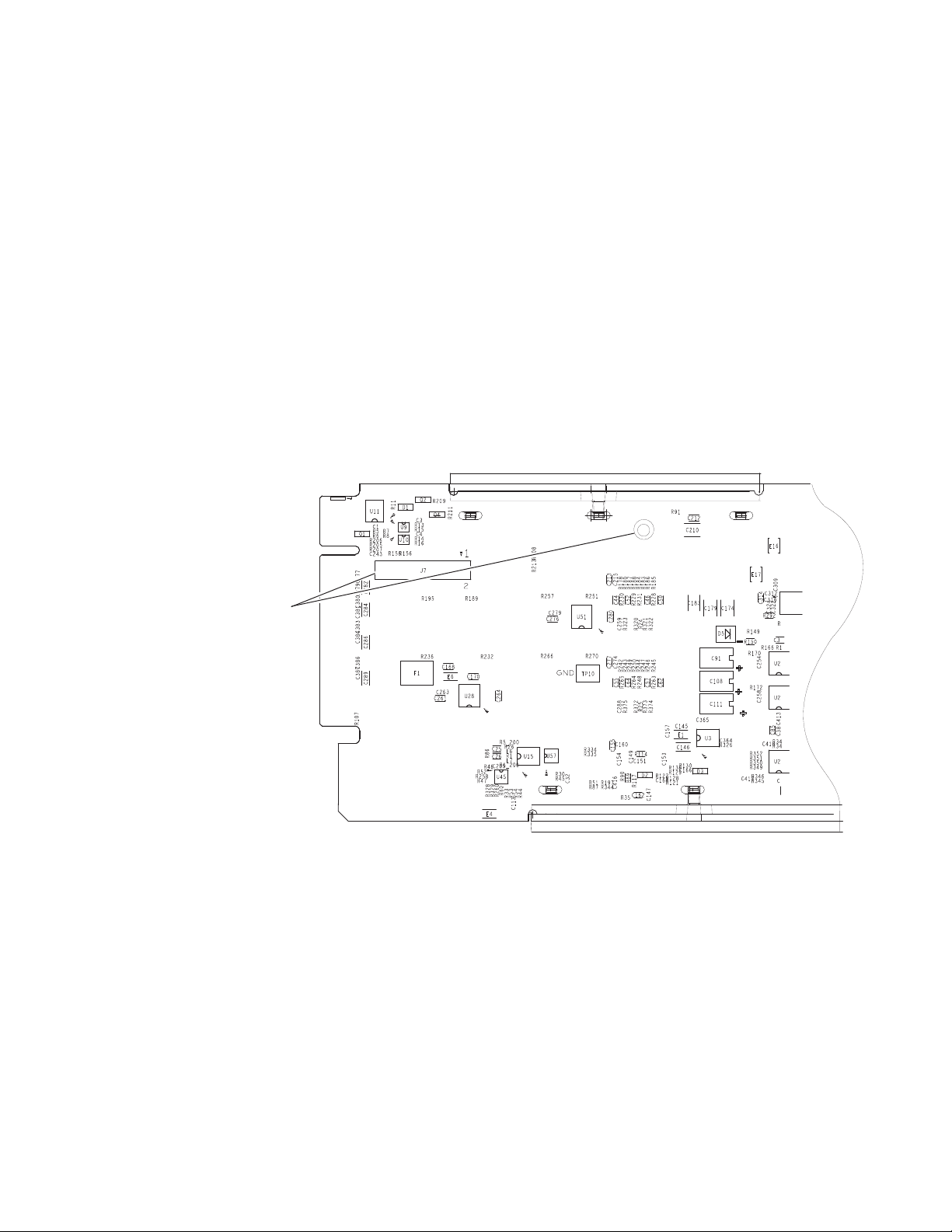
Install Genlock submodule
on back of circuit board.
Center submodule connector J1
over front module connector J7
and snap in place. From top side
of module, tighten the screw
provided to the standoff on the
circuit board.
8521_08
Installation
The 8900GEN-SM Genlock submodule will ship in a separate package, not
installed on the front module.
To install a Genlock submodule, follow these steps:
1. Locate the Genlock connector J7, on the back side of the 8977AP circuit
board (Figure 3).
2. Line up the connector on the submodule, J1, with J7 on the front
module and snap the submodule into place making sure the holes in
each circuit board line up.
3. To hold the submodule in place, attach the captive screw provided from
the top of the front module to the standoff on the submodule circuit
board.
Figure 3. Installing 8900GEN-SM Genlock Submodule
8977AP-4B/4U — Instruction Manual 13
Page 14
Installation
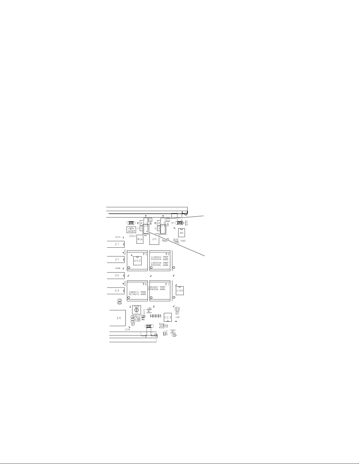
Frame Bus Jumpering
If you will be using this 8977AP module to distribute reference Frame Bus 1
(slot 1) or Frame Bus 2 (slot 3), you must set a jumper (GEN XMIT shown
in
Figure 4) on the front module circuit board for this purpose before
installing the module.
• Frame Bus 1 – to transmit the reference connected to the Reference In
BNC on the corresponding rear module on Frame Bus 1, set jumper J2
to
ENA (pins 1-2). This module must be installed in slot 1 of the frame
and configured on the Genlock web page (see the Genlock Web Page on
page 49) for
• Frame Bus 2 – to transmit the reference connected to the Reference In
BNC on the corresponding rear module on Frame Bus 2, set jumper J3
ENA (pins 1-2). This module must be installed in slot 3 of the frame
to
and configured on the Genlock web page (see the Genlock Web Page on
page 49) for
Note Both jumpers may be enabled. The module in slot 1 will only read the status
of jumper, J2. The module in slot 3 will only read the status of jumper, J3.
Auto in the Drive Frame Reference Bus pulldown.
Auto in the Drive Frame Reference Bus pulldown.
Figure 4. Setting Frame Bus Jumpers
8521_09
For Frame Bus 2 distribution, set
GEN XMIT jumper, J3
Pins 1-2 (ENA) or Pins 2-3 (DIS)
For Frame Bus 1 distribution, set
GEN XMIT jumper, J2
Pins 1-2 (ENA) or Pins 2-3 (DIS)
14 8977AP-4B/4U — Instruction Manual
Page 15
Front Module Installation
After installing the rear module and the 8900GEN-SM Genlock submodule
if required, install the front module as follows:
1. Unscrew and remove the front cover.
2. Insert the front module in the guides of the corresponding slot.
3. The module ejector tab (Figure 5) must be locked in its locking pin.
Figure 5. Front Module Ejection
Installation
Card Carriers
Front Module Side View
Card Carriers
Ejector Tab
Locking Pin
8521_03
Module installed
Slide top and bottom card carriers on module
over top and bottom guides on right of slot.
8977AP-4B/4U — Instruction Manual 15
Page 16
Cabling
8900BA-R
Reference Input
Audio Delay
Tracking Input
AES 1 Input
AES 2 Input
AES 3 Input
AES 4 Intput
AES 1 Output
AES 2 Output
AES 3 Output
AES 4 Output
Not Used
Not Used
8521_10
+
G
+
G
+
G
+
G
+
G
+
G
+
G
+
G
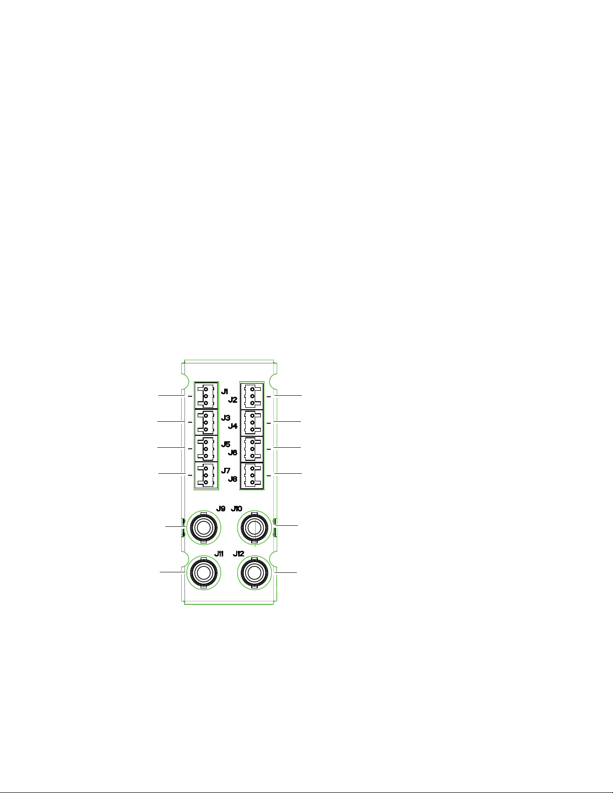
Cabling
Cabling to the 8977AP-4B and 8977AP-4U modules is done on the BNCs of
the 8900UE-R rear module or the three pin connectors on the 8900BA-R rear
module. Refer to
Figure 6 (8900BA-R) and Figure 7 on page 17 (8900UE-R)
for a detailed illustration of the rear connections.
The I/O Config web page (Figure 18 on page 31 for the 8977AP-4U and
Figure 19 on page 32 for the 8977AP-4B) shows the inputs and the outputs
assigned to the different connectors of the rear modules.
The 8977AP-4B and the 8977AP-4U outputs conform to the audio standards listed in the output specifications in Tab le 3 on page 56.
Figure 6 gives the inputs and the possible audio output connections for the
8977AP-4B modules. Balanced audio pinouts (+/-/ G) are also illustrated.
Note J10 and J12 are not used in this release.
Refer to Figure 7 on page 17 for the 8900UE-R inputs and outputs illustration.
Figure 6. 8900BA-R Rear Module
16 8977AP-4B/4U — Instruction Manual
Page 17
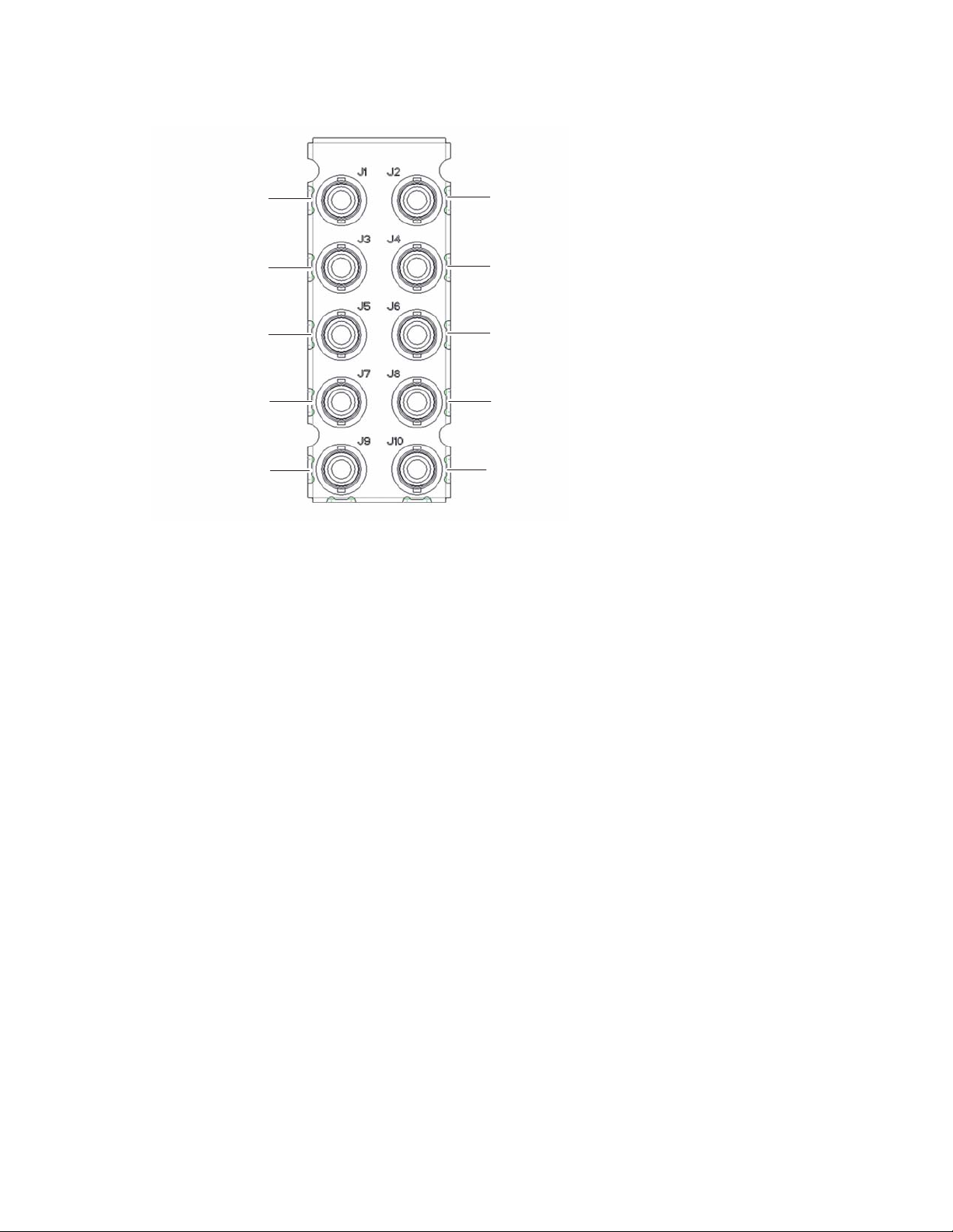
Figure 7. 8900UE-R Rear Module
8900UE-R
Reference Input
Audio Delay Tracking Input
AES 1 Input
AES 2 Input
AES 3 Input
AES 4 Input
AES 1 Output
AES 2 Output
AES 3 Output
AES 4 Output
8521_10
Cabling
8977AP-4B/4U — Instruction Manual 17
Page 18
Power Up
Power Up
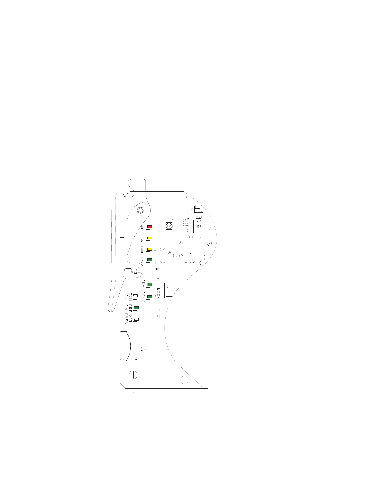
Operation Indicator LEDs
Upon power-up, the green PWR LED should light and the CONFIG,
FAULT, and COMM LEDs should illuminate during the module initializa
tion.
Note When a module is first plugged into a GeckoFlex frame, the 8900NET module
may report a momentary fault. This will clear once the module has booted up.
The on-board LED indicators on the front of the module are illustrated in
Figure 8. Refer to Tab le 1 on page 20 to see a complete list of possible oper-
ating conditions and the resulting indicator status of all LEDs.
Figure 8. LED Indicators - Front View of 8977AP Module
-
8521_06
18 8977AP-4B/4U — Instruction Manual
Page 19
Power Up
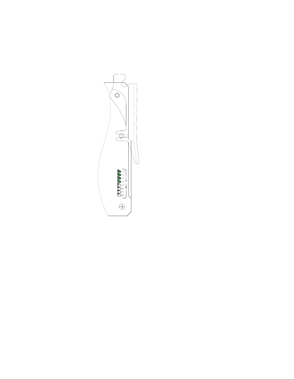
8521_07
Figure 9 shows the AES IN (1 to 8) LEDs. With a present audio input signal
connected, AES-IN (1 to 4) green LEDs should be on.
Note In this version, AES IN (5 to 8) LEDs are not used.
Figure 9. LED Indicators - Back View of the 8977AP module
8977AP-4B/4U — Instruction Manual 19
Page 20

Power Up
A red FAULT LED indicates an error situation and, when noted with the
other indicator LEDs, can indicate a specific problem area.
signal output and LED indications.
Table 1. LED Indicators
LED Indication Condition
FAULT
(red)
COMM
(yellow)
CONF
(yellow)
PWR
(green)
FRM1
(green)
FRM2
(green)
TDM IN
REF IN
(green)
OPT PRES
AES IN 1-4
(green)
AES IN 5-8
(green)
Off Normal operation
On continuously Module has detected internal fault.
Flashing Configuration problems or checking inputs and settings or missing audio
Off No activity on frame communication bus
On continuously Locate Module Command
Flashing Activity present on the frame communication bus
Off Module is in normal operation mode
On continuously Module is initializing, changing operating modes, or programming hardware
Off No power to module or modules DC/DC converter failed
On Normal operation, module is powered
Off Reference frame bus is disabled to frame on Genlock web page or no Genlock submodule is installed in slot 1
On Reference frame bus is enabled on Genlock web page and Genlock submodule is installed in slot 1
Off Reference frame bus is disabled to frame on Genlock web page or no Genlock submodule is installed in slot 3
On Reference frame bus is enabled on Genlock web page and Genlock submodule is installed in slot 3
N/A Not used in this version
Off The frame reference input coax is not present on the BNC Ref In or signal is not locked
On The frame reference input coax is present on the BNC Ref In and signal is locked
N/A
Off No AES input signal detected
On One or more AES input signal detected
N/A Not used in this version
Not used in this version
Tab le 1 describes
20 8977AP-4B/4U — Instruction Manual
Page 21

Remote Configuration
The 8977AP-4B and 8977AP-4U configuration and monitoring is performed using a web browser GUI interface or a networked Newton Control
Panel in the GeckoFlex frame (8900FFN). Each of these interfaces is
described below.
8900NET Module Information
Refer to the 8900NET Network Interface Module Instruction Manual from
4.0.2 version for information on the 8900NET Network Interface Module
and setting up and operating the GeckoFlex 8900 frame network.
Note Upgrade software and instructions for the 8900NET can be downloaded from
the Grass Valley web site. Refer to Contacting Grass Valley on page 4.
Newton Control Panel Configuration
Remote Configuration
A Newton Control Panel (hard or soft version) can be interfaced to the
GeckoFlex frame over the local network. Refer to the documentation that
accompanies the Newton Modular Control System for installation, config
uration, and operation information.
Control panel access offers the following considerations for module configuration and monitoring:
• Ability to separate system level tasks from operation ones, minimizing
the potential for on-air mistakes.
• Ability to group modular products—regardless of their physical loca-
tions—into logical groups (channels) that you can easily manipulate
with user-configured knobs.
• Recommended for real-time control of module configuration parame-
ters, providing the fastest response time.
Note Some module functions are not available with the Newton Control Panel,
such as factory default recalls.
-
8977AP-4B/4U — Instruction Manual 21
Page 22

Remote Configuration
An example of the Newton Configurator is shown in Figure 10.
Figure 10. Newton Configurator Example
Note A table of the Newton parameters is given in the Configuration Parameters
appendix on page 61.
Web Browser Interface
The web browser interface provides a graphical representation of module
configuration and monitoring.
Use of the web interface offers the following considerations:
• Provides complete access to all module status and configuration functions, including naming of inputs and outputs, factory parameter and
name default recalls, E-MEM functions, slot configurations and SNMP
monitoring controls.
• Web access will require some normal network time delays for processing of information.
• Configuration parameter changes may require pressing
processing time,
• Using the Web interface is recommended for setting up module signal
and slot names, and reporting status for SNMP and monitoring.
Enter, upload
and a manual screen refresh to become effective.
22 8977AP-4B/4U — Instruction Manual
Page 23

Remote Configuration
8431_08r1
The Links section lists the frame and its current modules. The selected link's Status
page is first displayed and the sub-list of links for the selection is opened. The sub-list
allows you to select a particular information page for the selected device.
Content display section
displays the information page
for the selected frame or module (frame slot icons are also
active links).
Refresh button for manual
update of page
Refer to the Status web page shown in Figure 11. The 8900 modules can be
addressed by clicking either on a specific module icon in the frame status
display or on a module name or slot number in the link list on the left.
Note The physical appearance of the graphics on the web pages shown in this
manual represent the use of a particular platform, browser and version of
8900NET module software. They are provided for reference only. Web pages
will differ depending on the type of platform and browser you are using and
the version of the 8900NET software installed in your system. This manual
reflects 8900NET version 4.0.2.
For information on status and fault monitoring and reporting shown on the
Status page, refer to the Status Web Page on page 28.
Figure 11. GeckoFlex Frame Status Web Page
Note The Refresh button must be clicked to update the page after any changes.
8977AP-4B/4U — Instruction Manual 23
Page 24

Remote Configuration
Pulldown Menus
Check box
Refresh button
Coarse Adjust
Fine Adjust
Enter
Status LED
Entry Field
High Limit
Status Indicator
Low Limit
Radio button
Button
Web Page Operations and Functional Elements
The following conventions and functional elements (shown at left) are used
in GeckoFlex web page operations. (The examples shown throughout this
manual represent 8900NET software version 4.0.2 or later):
• Pulldown menus allow you to choose selections from a list.
• Clicking on a button performs an immediate action such as recall of
defaults, clearing of states, learning configurations, and selecting all or
none of a selection.
• Radio buttons are used to make a choice of one parameter in a group.
• Check boxes are used when a selection can be enabled or included in a
group. Multiple check box selections or enables can be made for some
parameters.
Refresh button (circular arrow) is provided at the top of each web page
•A
for manual refresh to view recently changed parameters.
• Each numerical adjustment control has a
Coarse adjust button (left and
right top double arrows) which increases or decreases the step value by
a factor of 10. The
Fine adjust button (left and right inside single arrows)
increases or decreases the step value by 1.
To change a value, use the arrow button controls or enter a value into
the number field and select the
Enter button (*) or use the Enter key on
your keyboard. The Status Indicator bar will follow the value selected.
Use the Low and High Limit buttons to go directly to the lowest and
highest limits for the parameter.
• An entry field allows naming of various module functions such as
input or output signals, asset tag, and slot identification.
•The
Status LED icon reports communication status for the frame slot and
is a link to the module Status web page where Warnings and Faults are
displayed.
LED colors indicate:
• Green = Pass – no problems detected.
• Yellow = Configuration error warning (presence of one warning),
configuration mismatched or input missing.
• Red = Fault condition detected (presence of one alarm).
• Graphic and arrow colors used indicate the following:
• Green = Pass – signal or reference present, no problems detected.
• Red = Fault – fault condition.
• Yellow = Warning – signal is absent or has errors.
• Gray = Not monitored.
• White = Empty or not present.
24 8977AP-4B/4U — Instruction Manual
Page 25

• Text colors indicate:
• Black: Parameter names and information which can be modified.
• Blue: Read-only information about the module.
• Red: Warning.
Web Page Headers
Each web page has a Status and Identification Header as shown in
Figure 12 (8977AP-4U) and Figure 13 (8977AP-4B) below.
The header information on each web page (except Genlock web page)
includes the following:
Model and Description are read-only generated by the module.
•
Frame Location is defined on the GeckoFlex frame configuration web
•
page.
Slot number reports the module’s location in the frame.
•
Remote Configuration
Figure 12. Status Web Page Header – 8977AP-4U
Figure 13. Status Web Page Header – 8977AP-4B
When an 8900GEN-SM submodule is installed on either module, the
header will appear a shown in Figure 14.
Figure 14. Status Web Page Header – 8977AP-4U+GEN
8977AP-4B/4U — Instruction Manual 25
Page 26

Remote Configuration
8977AP-4B and 8977AP-4U Links and Web Pages
The web interface 8900 GUI provides the following links and web pages for
the 8977AP-4B and 8977AP-4U modules (
• Status web page – reports input and output signals and frame bus communication status and module information (page 28),
• I/O Config web page – shows the rear module layout and presence of
the signals on a specific connector, allows naming of each input and
enables or disables the signal reporting (page 31),
• Functional View web page – provides a graphical block diagram of the
configuration pages for the module with links to web pages (page 33),
• Input Status & Settings web page – reports information about the audio
stream, the delay tracking and the genlock inputs (page 34),
• Delay web page – allows the adjustment of the delay on each stream
and/or each audio channel, enables or disables the delay tracking and
displays the total delay (page 36),
• Gain web page – allows the adjustment of the audio gain, gives the level
of presence and clipping (page 38),
Figure 15 on page 27):
• Routing & Processing Pairs web page – describes the process on the
inputs (page 40),
• Output Status & Settings web page – enables or disables the AES CUV
bits pass through and sets AES resolution (page 43)
• User Settings web page – allows recalling of factory defaults for all
module parameters or factory signal names and provides a save/load
configuration file function (page 46),
• Genlock web page – appears only when the optional 8900GEN-SM submodule is installed on the module. This web page provides status
reporting for the external genlock reference and controls for enabling
the Genlock, matching the reference input to a selection standard, and
setting reference signal delay (page 49),
• System Config web page – sets output timing source, Reference Restore
parameters and Primary and Secondary Phase Difference (page 52),
and
• Slot Config web page – provides Locate Module, Slot Identification and
Slot Memory functions along with links to the frame alarm configuration web page (page 54).
26 8977AP-4B/4U — Instruction Manual
Page 27

Figure 15. 8977AP Web Page Links
Remote Configuration
8977AP-4B/4U — Instruction Manual 27
Page 28

Remote Configuration
Use
this
link
Status Web Page
The Status web page (Figure 16 on page 29 for the 8977AP-4U with an
8900GEN-SM submodule installed and Figure 17 on page 30 for the
8977AP-4B with no submodule) shows the signal status of the input
signal(s) and communication with the frame bus. Color coding of the
display indicates the signal status. Refer to
tional Elements on page 24 for an explanation of the color coding. The con-
tents of the web page header is explained on page 25.
Web Page Operations and Func-
Module Physical Structure
Status is reported for each of the following audio and video signals:
• Audio inputs – indicate the status of the four audio inputs (BNC or
3-pins connectors).
• DT Input – indicates the status of the audio delay tracking input.
• Ref 1 and Ref 2 In (from frame) – the Ref 1 arrow will be green when
Frame Bus 1 has been enabled on the module in slot 1. The Ref 2 arrow
will be green when Frame Bus 2 has been enabled on the module in
slot 3 of the frame.
• Frame Bus – indicates the status of the communication bus to the
8900NET module.
• Genlock Ref In – indicates the status of the external genlock reference
signal on the BNC.
• Local Ref – indicates the status of the internally generated genlock reference signal from the 8900GEN submodule to the front module.
• Ref Out – if the module is installed in slot 1, Ref 1 out is directed to the
Ref 1 In. If the module is installed in slot 3, Ref 2 out is directed to the
Ref 2 In.
On the Status web page any alarm or warning states will cause a warning
message to appear in the double bars area below the graphic.
Note The color of the LED status is managed by the 8900NET accordingly to the
alarms status.
Status
The front, rear, and Genlock (if present) modules status is given: PASS,
WARNING, ERROR or EMPTY.
Front Module
There are information about the module, such as Part Number, Serial
Number, Hardware Revision, Package version, Firmware Version, Soft
ware Version, Boot Version and Asset Tag number are given in a properties
section at the bottom of the Status web page.
28 8977AP-4B/4U — Instruction Manual
-
Page 29

Figure 16. Status Web Page for 8977AP-4U + GEN Module
Remote Configuration
8977AP-4B/4U — Instruction Manual 29
Page 30

Remote Configuration
The Status web page in Figure 17 illustrates the 8977AP-4B with a missing
audio input and no submodule installed. Note the message and warning
between the double lines below the graphic and the color of the Status LED.
Figure 17. Status Web Page for 8977AP-4B Module
30 8977AP-4B/4U — Instruction Manual
Page 31

I/O Web Page
Use
this
link
Use the I/O Config web page for the following:
Rear Module Configuration
All of the input and output connectors on the corresponding 8977AP-4U or
8977AP-4B rear module are illustrated on the I/O Config web page.
The inputs can be configured with the following controls:
•
•
Figure 18 for the 8977AP-4U and Figure 19 on page 32 for the 8977AP-4B
show the connectors of the two different rear modules available to cable
balanced or unbalanced audios.
Remote Configuration
Signal Names – type of the desired input name (up to 12 characters) into
the corresponding boxes for each input. The status of each input is indicated by the color of the display, the legend is under the table.
Reporting – raises alarms and warnings. The Status Reporting can be
enabled or disabled by selecting or deselecting the corresponding
checkbox in the
Reporting column for each input.
Note The outputs are not monitored in this application.
Figure 18. I/O Config Web Page for the 8977AP-4U
8977AP-4B/4U — Instruction Manual 31
Page 32

Remote Configuration
Figure 19. I/O Config Web Page for the 8977AP-4B
32 8977AP-4B/4U — Instruction Manual
Page 33

Functional View Web Page
Use
this
link
The Functional View web page (Figure 21) illustrates a block diagram of the
8977AP front module showing module functions and signal paths that are
active or inactive in the current configuration. It can be used as a link map
for configuring module functions. Each block has a link to the configura
tion page for that function.
• Color coding indicates active functions and signal flow. Grayed compo-
nents are inactive due to hardware and/or software constraints. Underlined module functions are links to the web page for that function.
• Use the Functional View to configure the 8977AP modules in the order
of the signal flow.
• Each web page shown in the Functional View will have links to the
<<Previous web page, the Functional View web page and the Next >> web
page at the bottom of the web page. Use the previous links to move
through the configuration web pages or return to the Functional View
web page (Figure 20).
Figure 20. Navigation Links
Remote Configuration
-
Figure 21 describes the front module processing as shown on the Func-
tional View web page.
Figure 21. Functional View Web Page
8977AP-4B/4U — Instruction Manual 33
Page 34

Remote Configuration
Use
this
link
Input Status and Settings Web Page
Use the Input Status and Settings web page (Figure 22 on page 35) for the
following:
Audio Inputs
• Input Stream Name – the signal name defined on the I/O Config web page
will appear in this field.
Signal State – this field reports the status of the input signal Present or
•
Not Present.
Sample Rate – indicates the rate of the audio input stream.
•
•
Mode – reports the number of bits: 16, 20, or 24 bits.
Audio Mode Status – shows the audio mode: PCM or Non-PCM.
•
Force Audio Mode – chooses the audio mode: PCM (Pulse Code Modula-
•
tion – a method of storing and transmitting uncompressed digital
audio), Non-PCM (non-audio data such as Dolby E or data), or Sync
PCM (audio that already has a 48 kHz sample rate).
Note When a Force Audio Mode selection is changed, you must manually set the
AES CUV Bits Pass Through control to Enabled or Disabled as desired on
the Output Status and Settings Web Page on page 43.
• AES Error Detected – reports any errors detected since the last time the
error status was cleared (
Errors or None).
Delay Tracking Input
• Name – this name cannot be modified.
Signal State – this field reports the status of the delay tracking input
•
signal as Present or Not Present.
Link – select this link to go to the Delay web page.
•
Genlock Input
• Name – the genlock input name defined on the I/O Config web page
will appear in this field.
Signal State – this field reports the status of the input signal Present, Not
•
Present or Not Supported.
Link – select this link to go to the Genlock web page.
•
Defaults Button
Select the Defaults button to restore the default Input signal source.
34 8977AP-4B/4U — Instruction Manual
Page 35

Figure 22. Input Status and Settings Web Page
Remote Configuration
8977AP-4B/4U — Instruction Manual 35
Page 36

Remote Configuration
Use
this
link
Delay Web Page
Use the Delay web page (Figure 23 on page 37) for the following:
• Input Stream – name of the input.
Input Name – name given in the I/O Config web page.
•
Delay Adjust – setting delay adjustments for each channel of the four
•
streams.
Delay both ch1&ch2 – setting delay adjustments for both channels together
•
of the four streams.
Tracking Delay – enable or disable the delay tracking. The amount of delay
•
tracking input status will be reported for each audio stream.
Total Delay – the total amount of delay (Delay Adjust + Tracking Delay)
•
will be reported in the Total Delay field for each audio stream.
Note When a delay has been applied to a channel on a stream, removing and rein-
serting the module or disconnecting and reconnecting the audio input may
cause a disturbance on the undelayed channel or stream for a period equal to
the delay.
In the case of a Non-PCM audio (input stream 2 as shown in Figure 23 on
page 37), a delay may only be applied on the stream. Channel delay shift is
not available. The input name is reported in pink.
In the case of Sync PCM audio (input streams 3 and 4 in Figure 23 on
page 37), no tracking delay is applied and the function is grayed out.
Note If a Non-PCM audio signal is detected and another audio mode is forced, a
warning “Input Stream is detected as Non-PCM” appears between the input
streams (not shown).
36 8977AP-4B/4U — Instruction Manual
Page 37
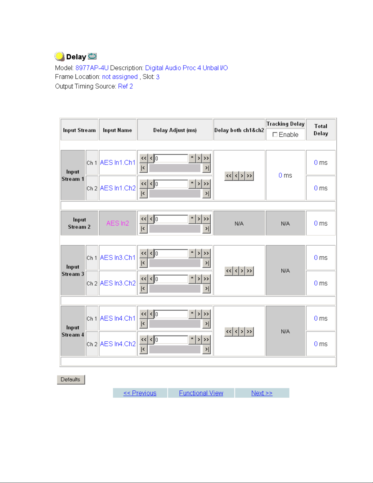
Figure 23. Delay Web Page
Remote Configuration
8977AP-4B/4U — Instruction Manual 37
Page 38

Remote Configuration
Use
this
link
Gain Web Page
Use the Gain web page (Figure 24 on page 39) for the following:
• Input Stream – name of the input stream.
Input Name – name given in the I/O Config web page.
•
Gain Adjust – adjustment for the selected channel.
•
Note Gain cannot be adjusted for channels set as Non-PCM.
• Gain both ch1&ch2 – adjusts both channels in a stream for the same
amount of gain.
Presence – the level status of each audio channel is reported as True or
•
False in the read-only channel status displays. If the level is > -40dBFS,
the presence will be reported as
Clip – the clipping of each audio channel is reported as True or False in the
•
read-only channel status displays. If the level is > -0.5dBFS, the clipping
will be reported as
True.
True.
38 8977AP-4B/4U — Instruction Manual
Page 39

Figure 24. Gain Web Page
Remote Configuration
8977AP-4B/4U — Instruction Manual 39
Page 40

Remote Configuration
Use
this
link
Routing & Processing Pairs Web Page
Use the Routing & Processing Pairs web pages (Figure 25 on page 41 for
Pair 1 and Pair 2 and Figure 26 on page 42 for Pair 3 and Pair 4) for the following:
• Input Channel Selection – name assigned on the I/O Config web page.
Processing – set the output processing for each channel (A and B) for
•
each audio pair (Pair 1 to 4) with the Processing pulldown to one of the
following output conditions:
• A - selects the audio present on A as the channel output.
• -A - inverts the audio present on A as the channel output.
• B - selects the audio present on B as the channel output.
• -B - inverts the audio present on B as the channel output.
• A + B - audio present on A and B are added together as the channel
output.
• -(A + B) - audio present on A and B are added together then
inverted as the channel output.
• A - B - audio present on B is subtracted from audio on A as the
channel output.
• - (A-B) - audio present on B is subtracted from audio on A then
inverted as the channel output.
• 1 kHz - places a 1 kHz (at -20 dBFS) tone on the channel output.
• 400 Hz - places a 400 Hz (at -20dBFS) test tone on the channel
output.
• Silence - forces the channel output to silence.
• ID - identifies Channels A and B with a 1 kHz tone at a -20dBFS
level that switches between Channel A and Channel B with a
repeating cadence of 1 second on Channel A (left) followed by a 3
second tone on Channel B. Each pair from 1-4 is indicated by that
number of bursts of 400 Hz at an 8 Hz rate when the 1 kHz tone
starts on a new channel.
Note An output processing mode cannot be selected on a channel with Non-PCM
audio and processing will be forced to bypass as shown in Figure 25 on
page 41.
• Output Pairs – Output names.
40 8977AP-4B/4U — Instruction Manual
Page 41

Figure 25. Routing & Processing Pairs Web Page – Pair 1 and Pair 2
Remote Configuration
8977AP-4B/4U — Instruction Manual 41
Page 42

Remote Configuration
Figure 26. Routing & Processing Pairs Web Page – Pair 3 and Pair 4
42 8977AP-4B/4U — Instruction Manual
Page 43

Output Status and Settings Web Page
Use
this
link
Use the Output Status and Settings web page (Figure 27 on page 45) to
monitor the audio outputs and to set the AES CUV Bits Pass Through and the
AES Resolution controls.
• Processed Stream Name – displays the name for each channel.
AES CUV Bits Pass Through – the control bits that are part of each subframe
•
of AES data are defined as C (Channel status), U (User), and V (Valid)
bits and the Z bit, which carries the AES block frame position block
start. For the control and status bits in the CUV positions of each audio
channel, and the Z marker for each stream (pair of channels), there is a
buffer on the module that handles the asynchronous timebase slips
between the input and output AES stream frequency.
This buffer will drop or repeat an entire block (occurring every 192 samples) of CUV bits when the two timebases cross a block boundary rather
than drop or repeat individual bits from the block.
A control is provided on the AES Outputs web page for enabling or disabling the controls bits in an AES signal called the AES C/U/V Bit Pass
Through
the AES output of the module (Pass Through disabled) or taken from
the AES stream coming from an audio input.
(Figure 27 on page 45). These bits may be generated locally at
Remote Configuration
• If the box is checked, refer to Table 2 on page 44.
• If the box is not checked, the C bit is calculated.
Note When a Force Audio Mode selection is changed on the Input Status and Set-
tings Web Page on page 34, you must manually set the AES CUV Bits Pass
Through control to Enabled or Disabled as desired.
• AES Resolution –
•If the
•If the
AES CUV Pass Through box is checked, the AES Resolution is dis-
played
chosen between 20 and 24 bits.
Non-Applicable and the AES resolution is 24 bits.
AES CUV Pass Through box is not checked, the resolution can be
8977AP-4B/4U — Instruction Manual 43
Page 44

Remote Configuration
Default Channel
Status Data mode
The module complies with all of the requirements listed below:
• When an audio input stream is processed and routed at the channel
level, the CUV bit pass through mode is automatically disabled because
the consistency of the channel status data cannot be ensured.
• The module always sets the Output channel status to PROFESSIONAL.
• The module always delivers a signal at an output sample rate of 48 kHz.
Tab le 2 reports the configuration capability and some channel status data
fields related to configuration.
Table 2. AES Output Settings: Channel Status Data Handling
PCM Mode
32 kHz
CUV Bit
Pass Though
Disable
PCM Mode
44.1 kHz
CUV Bit
Pass Though
Disable
PCM Mode
48 kHz
CUV Bit
Pass Though
Disable
PCM Mode
96 kHz
CUV Bit
Pass Though
Disable
Non-PCM
48 kHz
CUV Bit
Pass Though
Enable
Synchronous PCM
48 kHz
CUV Bit
Pass Though
Disable
Channel Status
Data Setup
AES CUV
Bit Pass Through
Enable
Output Channel
status is Consumer in
the incoming signal
AES CUV
Bit Pass Through
Enable
Output Channel
status is Professional in
the incoming signal
AES CUV
Bit Pass Through
Disable
Output Channel
status is Professional in
the incoming signal
AES Resolution
24 bits
CUV Bit
Pass Through
Enable/Disable
AES Resolution
20/24 bits
Output channel
status is
Professional
Output Sampling
Frequency
32 kHz
Output channel
status is
Professional
Output Sampling
Frequency
32 kHz
Output channel
status is
Professional
Output Sampling
Frequency
48 kHz
AES Resolution
24 bits
CUV Bit
Pass Through
Enable/Disable
AES Resolution
20/24 bits
Output channel
status is
Professional
Output Sampling
Frequency
44.1 kHz
Output channel
status is
Professional
Output Sampling
Frequency
44.1 kHz
Output channel
status is
Professional
Output Sampling
Frequency
48 kHz
AES Resolution
24 bits
CUV Bit
Pass Through
Enable/Disable
AES Resolution
20/24 bits
Output channel
status is
Professional
Output Sampling
Frequency
48 kHz
Output channel
status is
Professional
Output Sampling
Frequency
48 kHz
channel
Output
status is
Professional
Output Sampling
Frequency
48 kHz
AES Resolution
24 bits
CUV Bit
Pass Through
Enable/Disable
AES Resolution
20/24 bits
Output channel
status is
Professional
Output Sampling
Frequency
96 kHz
Output channel
tatus is
s
Professional
Output Sampling
Frequency
96 kHz
Output channel
status is
Professional
Output Sampling
Frequency
48 kHz
AES Resolution
24 bits
Not Applicable
Output channel
s
status i
Professional
Output Sampling
Frequency
48 kHz
Output channel
status is
Professional
Output Sampling
Frequency
48 kHz
Output channel
status is
Professional
Output Sampling
Frequency
48 kHz
AES Resolution
24 bits
CUV Bit
ss Through
Pa
Enable/Disable
AES Resolution
20/24 bits
Output channel
status is
Professional
Output Sampling
Frequency
48 kHz
Output channel
status is
Professional
Output Sampling
Frequency
48 kHz
Output channel
status is
Professional
Output Sampling
Frequency
48 kHz
44 8977AP-4B/4U — Instruction Manual
Page 45

Figure 27. Output Status and Settings Web Page
Remote Configuration
8977AP-4B/4U — Instruction Manual 45
Page 46

Remote Configuration
Use
this
link
User Settings Web Page
The User Settings web page (Figure 28) provides the following File Operations for saving and recalling user settings and factory defaults:
• Save to... and Load from... functions are provided for saving the current
module configuration to a file or loading a previously saved file, and
• Factory recall for default settings and default signal names.
Figure 28. User Settings Web Page
File Operations
Configuration files from the module may be saved to a file and stored
offline for later recall.
To save a file, do the following:
1. Save the current configuration on the module to a file by selecting the
Save to... button which will bring up the File Download screen (not
shown).
2. In the File Download screen select Save.
3. This will bring up the Save As screen shown in Figure 29 on page 47.
4. Enter a name in the File name field. This file is saved as a .bin type.
46 8977AP-4B/4U — Instruction Manual
Page 47

Figure 29. Save Module Configuration.
Remote Configuration
To load and recall a file, do the following:
1. Selecting the Load From... button on the User Settings web page
(Figure 28 on page 46) which will bring up the Load Settings web page
shown in Figure 30.
2. Enter a path and file name or select Browse... to locate the directory
where the files have been saved.
Figure 30. Load Module Configuration.
8977AP-4B/4U — Instruction Manual 47
Page 48

Remote Configuration
3. This will bring up the Choose File screen shown in Figure 31.
Figure 31. Choose File Screen
4. Select a file to load and then press Open to bring the file into the filename
field.
5. Press the Load button in the Load From... web page (Figure 30 on
page 47) to load the file to the module.
Recall Factory Defaults and Names
Use the two buttons at the bottom of the web page to do the following:
• Set Factory Defaults – select the Set Factory Defaults button to recall factory
settings to the module. Defaults for all module parameters are listed in
Table 5 on page 61.
Set Factory Names – select the Set Factory Names button to recall factory
•
signal names to the module. Defaults for all signal names are displayed
on the I/O Config web page shown in Figure 18 on page 31 and
Figure 19 on page 32.
48 8977AP-4B/4U — Instruction Manual
Page 49

Genlock Web Page
Use
this
link
The Genlock web page (Figure 32 on page 51) is present on 8977AP controls
when an 8900GEN-SM submodule is installed on the module.
Refer to the 8900GEN-SM Installation Manual available online for complete
details for configuring the 8900GEN-SM submodule.
This web page provides reporting status for the following genlock status
items:
Genlock – reports status of Genlock function as Enabled or Freerun.
•
Status – reports whether the reference input is Locked or Not Locked.
•
Firmware Version – reports the firmware version of the 8900GEN-SM sub-
•
module installed on this 8977AP module.
Hardware Revision – reports the hardware revision of the 8900GEN-SM
•
submodule installed on this 8977AP module.
Ref Input Standard – reports the reference input standard as detected by
•
the 8900GEN-SM submodule that is connected to the Genlock BNC on
the rear module.
Remote Configuration
The input standards are NTSC, PAL, 1080i/59.94, 720p/59.94, 1080i/50,
720p/50, 1080p/24, 1080sF/24, AES 48K, AES 96K, Word Clock 48K, or
Work Clock 96K.
• Output Bus Frame Rate – reports the frame rate being output on the frame
bus.
Note The Output Bus Frame Rate is always reported as an SD frame rate for all
input reference standards including audio.
• Output Bus – reports the reference bus (Ref Bus 1 or Ref Bus 2) being
output from the submodule.
Genlock Control
The Genlock submodule may be configured with the following controls:
• Genlock – select one of the radio buttons to Enable or Freerun (not locked
to external reference).
nput Standard Selection – use this control to set the input standard needed
• I
for the reference input.
Loop Bandwidth – set the loop bandwidth to Low Jitter or Fast Lock
•
depending on the type of reference input.
For example, if Low Jitter is selected and the Status is still Invalid after one
minute has passed, the input reference has excessive wander that
cannot be tracked in
is Locked after about 10 seconds.
8977AP-4B/4U — Instruction Manual 49
Low Jitter mode. Switch to Fast Lock and verify Status
Page 50

Remote Configuration
Genlock Bus Timing
Use the following controls to adjust the output timing of the genlock reference signal from this submodule:
• Line Offset – adjust the reference timing stream by standard definition
line steps up to one full frame.
Coarse Offset – provides coarse adjustment of the reference timing stream
•
by steps up to 37 ns.
Fine Offset – provides fine adjustment of the reference timing stream by
•
steps up to 37 ns.
Drive Frame Reference Bus – Set to Auto or Off. If Auto is selected, Ref 1 or
Ref 2 is provided if it is locked.
If Off is selected, the reference on the frame bus is not sent out.
Defaults Button
Select the Defaults button to restore the default genlock parameters.
50 8977AP-4B/4U — Instruction Manual
Page 51

Figure 32. Genlock Web Page
Remote Configuration
8977AP-4B/4U — Instruction Manual 51
Page 52

Remote Configuration
Use
this
link
System Config Web Page
Use the System Config web page (Figure 33 on page 53) to perform the fol-
lowing functions on the module:
Output Timing
Select the Primary and Secondary output timing source for the module as
either
on this module),
slot 1 and jumpered for outputting a Ref 1 frame bus),
submodule is mounted on module in slot 3 and jumpered for outputting a
Ref 2 frame bus) or
of each reference source will be reported in the Status and Genlock
columns.
Note The internal mode is mainly implemented for test and debug purposes during
When a secondary reference source is selected that is different than the Primary, the module can be configured to switch automatically to the Secondary selected if the Primary is lost or becomes unlocked or invalid. If you
do not want this action of switching to a Secondary, set the Primary and
Secondary sources to the same source.
Local (external reference from the 8900GEN-SM submodule mounted
Ref 1 (8900GEN-SM submodule is mounted on module in
Ref 2 (8900GEN-SM
Internal (local oscillator). The signal and genlock status
the system setup of the module or in a standalone configuration where no
timing reference is required.
Refer to 8900GEN-SM Genlock Submodule Installation on page 12 for an overview of using the 8900GEN-SM submodule for reference timing. Also refer
to the 8900GEN-SM Installation Manual available online for complete details
using this submodule for timing applications.
Reference Restore
If the Primary source has failed and a Secondary source is selected and
valid, the following controls allow you to set the module to switch back to
the Primary automatically or manually and determine the amount of time
before the Primary is restored.
• Switch to Primary – set this control to Manual if you wish to manually return
to the Primary reference when it becomes valid or locked again or
to allow the module to switch back to the Primary reference.
Reference Switchback Delay – When the control above is set for Auto, set
•
the amount of time to allow between switching from the Secondary reference back to the restored Primary. The switchback time has a
minimum recovery time of approximately 30 seconds to assure that the
Primary is locked and valid before the module switches back to that
source.
Auto
52 8977AP-4B/4U — Instruction Manual
Page 53

Remote Configuration
Primary - Secondary Phase Difference
This graphic is provided to show the total phase difference between the
Primary and Secondary reference signals. When the bar is green and
remains in the area before the horizontal indicator, the two references are in
a range where switching between the two will show no measurable distur
bance in the output video (approximately 72 ns).
When the phase difference is larger than the recommended amount, the bar
will indicate by showing a second red bar. This indicates that the phase difference is now such that switching between the two references will show a
disturbance in the output. This can be caused by a loss of one of the references or a mis-adjustment in the reference output delay of either reference.
The total phase error shown in this graphic represents approximative 1
microsecond.
Figure 33. System Config Web Page
-
8977AP-4B/4U — Instruction Manual 53
Page 54

Remote Configuration
Use
this
link
Slot Config Web Page
Use the Slot Config web page (Figure 34 on page 55) to perform the following functions on the module:
• Locate Module – selecting the Flash selection in the pulldown button
flashes the yellow COMM LED on the front of the module so it can be
located in the frame.
Slot Identification – You may identify the module by typing a specific
•
name in the
module and travels with the 8900NET module if it is moved to another
frame. Select
An asset identification may be entered in the Asset Tag field up to 31
characters. This will appear on the module Status web page and in the
NetConfig inventory report.
• Slot Memory – the slot configuration for each module is automatically
saved periodically (once an hour) to the 8900NET module in that frame.
You may also select the
current configuration for this slot. The configuration is saved on the
8900NET module. If the 8900NET module is removed or powered
down, the stored configurations are not saved.
Name field. The assigned name is stored on the 8900NET
Default to enter the factory default module name.
Learn Module Config button at any time to save the
When the Restore upon Install box has been checked, the current configuration saved to this slot is saved as slot memory. When the current
module is removed and another module of the same type is installed,
the configuration saved to the 8900NET module will be downloaded to
the new module. The box must be checked before the current module
with the saved configuration is removed.
Note Allow at least 5 seconds before inserting the new module into the slot.
Only the same module type, with the same version software should be
installed in this slot. Inserting a similar module with a different version
software can cause unexpected results. If a different type of module is
installed in this slot, a warning message will state that the original
module type has been replaced with another module type. In this case,
a
Clear button will appear allowing you to clear the stored configuration
from the previous module.
• Frame Health Reporting – This web page allows configuration of the alarms
and warnings that are reported to the external Frame Health Alarm
connector on the rear of the GeckoFlex frame. Refer to 8900NET Instruc-
tion Manual for more details.
LED Reports – This link appears when the 8900NET module has software
•
version 4.0.2 or later installed. When the link is selected, a read-only
status report of the 8900NET Hardware Switch state is given. In the
LED Reporting section of the web page, LED Reporting on the 8900NET
module can be enabled or disabled as desired.
54 8977AP-4B/4U — Instruction Manual
Page 55

Remote Configuration
• SNMP Trap Reports – Select the SNMP Trap Reports link to open the
8900NET SNMP Reporting web page. this link will only be present
when SNMP Agent software has been installed on the 8900NET
module. This web page allows configuration of which alarms and
warnings that are reported to the SNMP management software.
Refer to 8900NET Instruction Manual for more details on these links.
Figure 34. Slot Config Web Page
8977AP-4B/4U — Instruction Manual 55
Page 56

Specifications
Specifications
Table 3. 8977AP Specifications
Parameter Value
Environmental / Miscellaneous
ANSI/UL60950-1
CAN/CSA C22.2, No. 60950-01
cULus certification File number: E300838
Safety
EMC
EU marking 93/68/EEC (22/07/93)
Climatic specifications
Power consumption 6 Watts + 0.7 Watts with 8900GEN-SM submodule
Digital Audio Inputs
Digital audio input signal AES3-2003, Tech 3250-E AES3-id-2001
Number of inputs Up to 4 Up to 4
Input names AES 1, 2, 3, 4 AES 1, 2, 3, 4
Connector type Three-pin terminal blockBNC
Common range mode +/- 10V, 50Hz to 20kHz N/A
Differential voltage range 200mV to 10V p-p 200mV to 2V p-p
Input return loss > 20dB (100kHz - 128FS) > 20dB (100 kHz - 128FS)
Input impedance 110 Ohms +/- 20 % 75 Ohms +/- 20 %
Sampling rates supported (FS) 32 kHz, 44.1 kHz, 48 kHz, 96 kHz 32 kHz, 44.1 kHz, 48 kHz, 96 kHz
Sampling rate accuracy +/-100ppm +/-100 ppm
Resolution supported 16 bits, 20 bits, 24 bits 16 bits, 20 bits, 24 bits
IEC 60950-1
EN60950-1
73/23/EEC Low voltage directive
89/336/EEC directive
FCC Class A CISPR Pub. 22 (1985)
EN55103-1 (1997)
EN55103-2 (1997)
ETS 300 019-1-3 c
(Feb. 1992)
lass 3.1
Balanced Inputs Unbalanced Inputs
Safety of Information Technology
Equipment, including Electrical
Business Equipment (2003).
Safety of Information Technology
Equipment, including Electrical
Business Equipment.
Safety of Information Technology
Equipment, including Electrical
Business Equipment (2003).
Safety of Information Technology
Equipment, including Electrical
Business Equipment (2001).
(19/02/73) amended by
93/68/EEC (22/07/93)
(05/05/89) amended by
93/68/EEC (22/07/93)
Operating temperature (for
8900FFN model):
+ 0°C to + 45°C
operating humidity: 10% to 95%
non-condensing
56 8977AP-4B/4U — Instruction Manual
Page 57

Specifications
Table 3. 8977AP Specifications
Parameter Value
Digital Audio Outputs
Balanced Outputs Unbalanced Outputs
Digital audio output signal AES3-2003, Tech 3250-E AES3-id-2001
Number of outputs Up to 4
Output names AES 1, 2, 3, 4
Connector type Three-pin terminal blockBNC
Data jitter +/- 20ns
Output rise / fall time 5ns to 30ns @ 110 Ohms 37ns +/- 7ns @ 75 Ohms
Differential voltage range 2 to 7V @ 110 Ohms 1V +/- 20% @ 75 Ohms
Output return loss > 15dB (100 kHz - 128FS)
Output impedance 110 Ohms +/- 20 % 75 Ohms +/- 20 %
Sampling rates (FS) 48 kHz
Output resolution 20 or 24 bits
DT Input (Audio Delay Tracking)
Audio delay tracking input Conforming to Tektronix 118AS Interface
Number of inputs 1
Connector type BNC
Electrical interfaceOne wire serial (RS232 type) interface
BAUD = 1200
RS232 characteristics
Electrical Length (Delay)
Sync-PCM/Non-PCM throughput 280 microseconds
PCM mode throughput
Other Parameters
Maximum delay 10s in 1ms steps
Gain (40; +6dB) in 0.1dB steps
Output processing modes Silence, A, -A, B, -B, A+B, -(A+B), A-B, -(A-B), 1 kHz, 400 Hz, ID tone
Parity = Even
Bits/words = 7
Stop bits = 1
32 kHz:
44.1 kHz:
48 kHz:
96 k Hz:
3.2 ms
3.3 ms
3.9 ms
1.7 ms
8977AP-4B/4U — Instruction Manual 57
Page 58

Service
Service
Power-up Diagnostics Failure
Troubleshooting
The 8977AP modules make extensive use of surface-mount technology and
programmed parts to achieve compact size and adherence to demanding
technical specifications. Circuit modules should not be serviced in the field
unless otherwise directed by Customer Service.
If the module has not passed self-diagnostics, do not attempt to troubleshoot. Return the unit to Grass Valley (see Module Repair on page 59).
Electronic Circuit Breaker
The electronic circuit breaker works during a fault condition or an overcurrent which stops the module.
Remove the module and replace it in the frame. If the problem persists,
please contact Grass Valley Customer Service with the contacts given on
page 4.
Table of Alarms
Ta bl e 4 describes the different type of alarms generated on the module.
Table 4. List of Alarms for 8977AP Module
Status
Alarm
type
Pass Genlock module is not installed Green Genlock missing No
Fault Genlock submodule failed, replaceRedGenlock Failure No
Fault Power supply bad Red Problem of power supply Yes
Fault FPGA failure Red FPGA not loaded Yes
Warning Wrong Rear Module (incompatible with 8977AP-4U) Yellow Rear module is different of 8900UE-R Yes
Warning Wrong Rear Module (incompatible with 8977AP-4B) Yellow Rear module is different of 8900BA-R Yes
Warning Ref 1 is Not Present Yellow Ref 1 from FrameRef 1 is missing Yes
Warning Ref 2 is Not Present Yellow Ref 2 from FrameRef 2 is missing Yes
Warning Local Ref is Not Present Yellow Input ref is not detected Yes
Warning Redundant Ref in Not Present Yellow The second ref selected is missing Yes
Warning Audio Input: AES 1 Input Signal Not Detected Yellow No AES 1 input detected Yes
Warning Audio Input: AES 2 Input Signal Not Detected Yellow No AES 2 input detected Ye
Warning Audio Input: AES 3 Input Signal Not Detected Yellow No AES 3 input detected Yes
Web Page Description
LED
Status
Comments
reported
to the
8900Net
&SNMP
s
58 8977AP-4B/4U — Instruction Manual
Page 59

Service
Table 4. List of Alarms for 8977AP Module
Status
Alarm
type
Warning Audio Input: AES 4 Input Signal Not Detected Yellow No AES 4 input detected Yes
Warning Audio Delay Tracking Input: Signal Not Detected Yellow No audio delay tracking input detected after 30 seconds Yes
Pass Audio Mode: AES 1 Mismatch Mode (audio
PCM/Non-PCM mode detected different of mode
selected)
Pass Audio Mode: AES 2Mismatch Mode (audio
PCM/Non-PCM mode detected different of mode
selected)
Pass Audio Mode: AES 3 Mismatch Mode (audio
PCM/Non-PCM mode detected different of mode
selected)
Pass Audio Mode: AES 4 Mis
PCM/Non-PCM mode detected different of mode
selected)
Web Page Description
match Mode (audio
LED
Status
Green
Green
Green
Green
Comments
PCM on AES 1 status is different of the PCM setting
PCM on AES 2 status is different of the PCM setting
PCM on AES 3 status is different of the PCM setting
PCM on AES 4 status is different of the PCM setting
Note Please refer to the Figure 8 on page 18, Figure 9 on page 19, and Table 1 on
page 20 for the status meaning and the color of the LEDs.
reported
to the
8900Net
&SNMP
No
No
No
No
Module Repair
If the module is still not operating correctly, replace it with a known good
spare and return the faulty module to a designated Grass Valley repair
depot. Call your Grass Valley representative for depot location.
Refer to Contacting Grass Valley on page 4 at the front of this document for
the Grass Valley Customer Service Information number.
8977AP-4B/4U — Instruction Manual 59
Page 60

Functional Description
Functional Description
A block diagram of the 8977AP is shown in Figure 35.
Figure 35. 8977AP Block Diagram
60 8977AP-4B/4U — Instruction Manual
Page 61

Configuration Parameters
This appendix provides a complete summary of the 8977AP functions and
a comparison of the functionality available with the web page and Newton
control panel control type along with the ranges and default values for each
parameter in
Table 5. 8977AP Configuration Parameters
Ta bl e 5.
Description Default
Drive Frame Reference Bus
Input Standard Status
Genlock
Input Standard Selection NTSC
Loop Bandwidth
Line Offset
Coarse Offset
Fine Offset
Genlock
Input Frame Rate Status
Status
Output Bus
Output Frame Rate
Switch to Primary Ref
Switch Back After Primary Restored
Auto Auto/OFF GenlockGLBusDrv
Enable Enable or Freerun Genlock GLEnable
Fast LockFast Lock / Low Jitter Genlock GLLoopBW
0 [0 - 624] Genlock GLLnOff
0 [0 - 1727] GenlockGLcors
0 [0 - 255] GenlockGLfine
Status Freerun / Enabled GenlockGLstatus
Status Freerun / Invalid / Locked GenlockGLStat
Status Ref 2 / Ref 1 / Local GenlockGLOutBus
Status 29.97 / 25 / 0 Genlock GLOutFR
-Switching System Config Sw2PriRef
Auto Auto / Manual System Config RefSwBk
Range/choices
resolution
NTSC,
PAL,
1080i/59.94,
1080i/50,
720p/50,
720p/59.94,
1080p/24,
1080sf/24,
AES48K,
AES96K,
Word Clock 48K,
Word Clock 96K
NTSC,
PAL,
1080i/59.94,
1080i/50,
720p/50,
720p/59.94,
1080p/24,
1080sf/24,
AES48K,
AES96K,
Word Clock 48K,
Word Clock 96K
29.97 / 25 / 24 / 48 /
0 / 96
Web Page / Function
Name
Genlock GLInStd
Genlock GLInSEl
Genlock GLInFR
Newton Control
Panel
8977AP-4B/4U — Instruction Manual 61
Page 62

Configuration Parameters
Description Default
Reference Switchback Delay
Delay Stream 1 Channel 1
Delay Stream 1 Channel 2
Delay Stream 2 Channel 1
Delay Stream 2 Channel 2
Delay Stream 3 Channel 1
Delay Stream 3 Channel 2
Delay Stream 4 Channel 1
Delay Stream 4 Channel 2
Delay Stream 1 Both Ch1 Ch2
Delay Stream 2 Both Ch1 Ch2
Delay Stream 3 Both Ch1 Ch2
Delay Stream 4 Both Ch1 Ch2
Gain Stream 1 Both Ch1 Ch2
Gain Stream 2 Both Ch1 Ch2
Gain Stream 3 Both Ch1 Ch2
Gain Stream 4 Both Ch1 Ch2
Gain Stream 1 Channel 1
Gain Stream 1 Channel 2
Gain Stream 2 Channel 1
Gain Stream 2 Channel 2
Gain Stream 3 Channel 1
Gain Stream 3 Channel 2
Gain Stream 4 Channel 1
Gain Stream 4 Channel 2
Level Detect Stream 1 Channel 1
Level Detect Stream 1 Channel 2
Level Detect Stream 2 Channel 1
Level Detect Stream 2 Channel 2
Level Detect Stream 3 Channel 1
Level Detect Stream 3 Channel 2
Level Detect Stream 4 Channel 1
Level Detect Stream 4 Channel 2
Table 5. 8977AP Configuration Parameters
Range/choices
resolution
30.94 (30 -93.97seconds)System Config RefSwDly
0
0 Delay Delay 1-2
0 Delay Delay 2-1
0 Delay Delay 2-2
0 Delay Delay 3-1
0 Delay Delay 3-2
0 Delay Delay 4-1
0 Delay Delay 4-2
0 Delay Delay 1
0 Delay Delay 2
0 Delay Delay 3
0 Delay Delay 4
0
0GainGain 2
0GainGain 3
0GainGain 4
0 Gain Gain 1-1
0 Gain Gain 1-2
0 Gain Gain 2-1
0 Gain Gain 2-2
0 Gain Gain 3-1
0 Gain Gain 3-2
0 Gain Gain 4-1
0 Gain Gain 4-2
Status
Status Gain 1-2 LVL DETECT
Status Gain 2-1 LVL DETECT
Status Gain 2-2 LVL DETECT
Status Gain 3-1 LVL DETECT
Status Gain 3-2 LVL DETECT
Status Gain 4-1 LVL DETECT
Status Gain 4-2 LVL DETECT
[0-10000ms]
[-40dB - +6dB]
Tr ue /F al se
Web Page / Function
Name
Delay Delay 1-1
Gain Gain 1
Gain 1-1 LVL DETECT
Newton Control
Panel
62 8977AP-4B/4U — Instruction Manual
Page 63

Table 5. 8977AP Configuration Parameters
Description Default
Level Clip Stream 1 Channel 1
Level Clip Stream 1 Channel 2
Level Clip Stream 2 Channel 1
Level Clip Stream 2 Channel 2
Level Clip Stream 3 Channel 1
Level Clip Stream 3 Channel 2
Level Clip Stream 4 Channel 1
Level Clip Stream 4 Channel 2
Processing for Output Pair 1 ChA A
Processing for Output Pair 1 ChB B
Processing for Output Pair 2 ChA A
Processing for Output Pair 2 ChB B
Processing for Output Pair 3 ChA A
Processing for Output Pair 3 ChB B
Processing for Output Pair 4 ChA A
Processing for Output Pair 4 ChB B
Output 1 AES CUV bits pass through Enable
Output 2 AES CUV bits pass through Enable Output Status & Settings Out CUV 2
Output 3 AES CUV bits pass through Enable Output Status & Settings Out CUV 3
Output 4 AES CUV bits pass through Enable Output Status & Settings Out CUV 4
Output 1 AES Resolution N/A
Output 2 AES Resolution N/A Output Status & Settings Out Res 2
Output 3 AES Re
Output 4 AES Resolution N/A Output Status & Settings Out Res 4
Output Timing Source Internal Ref1, Ref2, Local, Internal System Config OutClk
Input Stream Signal State 1 Status
Input Stream Signal State 2 Status Input Status & Settings 2 State
Input Stream Signal State 3 Status Input Status & Settings 3 State
Input Stream Signal State 4 Status Input Status & Settings 4 State
Force Audio Mode Input Stream 1 Status
Force Audio Mode Input Stream 2 Status Input Status & Settings Mode 2
Force Audio Mode Input Stream 3 Status Input Status & Settings Mode 3
Force Audio Mode Input Stream 4 Status Input Status & Settings Mode 4
solution N/A Output Status & Settings Out Res 3
Status
Status Gain 1-2 Clip
Status Gain 2-1 Clip
Status Gain 2-2 Clip
Status Gain 3-1 Clip
Status Gain 3-2 Clip
Status Gain 4-1 Clip
Status Gain 4-2 Clip
Range/choices
resolution
Tr ue /F al se
Silence,
A,
-A,
B,
-B,
A+B,
-(A+B),
A-B,
-(A-B),
1 kHz,
400 Hz,
ID tone
Enabled / Disabled
20 bits, 24 bits, N/A
Present / Not Present
PCM / Non-PCM /
Sync-PCM
Web Page / Function
Name
Gain 1-1 Clip
Routing & Processing
Pairs
Routing & Processing
Pairs
Routing & Processing
Pairs
Routing & Processing
Pairs
Routing & Processing
Pairs
Routing & Process
Pairs
Routing & Processing
Pairs
Routing & Processing
Pairs
Output Status & Settings Out CUV 1
Output Status & Settings Out Res 1
Input Status & Settings 1 State
Input Status & Settings Mode 1
ing
Newton Control
Panel
Proc 1A
Proc 1B
Proc 2A
Proc 2B
Proc 3A
Proc 3B
Proc 4A
Proc 4B
8977AP-4B/4U — Instruction Manual 63
Page 64

Configuration Parameters
64 8977AP-4B/4U — Instruction Manual
Page 65

Index
Numerics
8900BA-R rear module
cabling diagram
I/O Config web page 31
installation 11
8900GEN-SM Genlock submodule
configuration
firmware and hardware version 49
installation 13
Instruction Manual 49
overview 12
8900NET module
information
software requirement 10
8900UE-R rear module 17
cabling diagram 17
I/O Config web page 31
installation 11
8977AP
block diagram
features 9
servicing 58
16
49
21
60
C
cabling 16
clipping (audio) 38
COMM LED 20
CONFIG LED 20
configuration
summary table
Control panel 21
61
D
delay adjustments
web page
delay tracking input 28
enabling 36
name and status 34
specification 57
Delay web page 36
Digital Audio Inputs
specifications
documentation online 4
DT Input 28
36
56, 57
A
AES CUV Bits Pass Through control 43
AES Errors 34
AES IN LEDs 19, 20
AES Resolution 43
alarms
reporting on Status web page
table summary 58
Arrow colors 24
Asset Tag assignment 54
Audio inputs arrows 28
28
B
Blank rear adapter cover 11
Block diagram 60
8977AP-4B/4U — Instruction Manual 65
E
electronic circuit breaker 58
F
factory default names
remote control
factory defaults
recall with remote controls
FAQ database 4
FAULT LED 20
file operations (save and load) 46
Force Audio Mode 34
Frame bus
jumpering
overview 12
48
48
14
Page 66

Index
reference 12
status arrow 28
Frame Health Reporting 54
Frame Location 25
frequently asked questions 4
FRM1 LED 20
FRM2 LED 20
front module
installation
Functional View web page 33
15
G
gain adjustment 38
Gain web page 38
GeckoFlex frame 10
Genlock web page 49
Graphical user interface (GUI) 26
Graphics colors 24
Grass Valley web site 4
M
Module ejector tab 15
N
NetCentral application 10
Newton control panel 21
O
online documentation 4
output processing 40
Output Status and Settings web page 43
output timing
choosing reference
52
P
Power consumption 56
Primary - Secondary Phase Difference 53
PWR LED 18, 20
I
I/O Config web page 31
Input Status and Settings web page 34
installation
8900GEN-SM Genlock submodule
front module 15
rear module 11
internal reference 12
13
L
Learn Module Config 54
LED Reporting 54
LEDs
colors and meanings
on top of circuit board 18
summary table 20
Local Reference
on Status web page
overview 12
Locate Module 54
Locking pin 15
24
28
R
REF IN LED 20
Reference Out 28
Reference Restore controls 52
Reference Switchback Delay control 52
Refresh button 24
Remote control 9
Reporting
enabling and disabling
Restore upon Install 54
Retainer strips 11
Routing and Processing Pairs web page 40
31
S
Sampling Rates Supported 56, 57
Signal names
I/O web page
Slot Config web page 54
Slot Identification 54
Slot Memory 54
Slot number 25
31
66 8977AP-4B/4U — Instruction Manual
Page 67

SNMP Trap Reports 55
software download from web 4
Specifications 56
Status LED
overview
Status web page 28
Switch to Primary control 52
System Config web page 52
24
T
Text colors 25
troubleshooting 58
U
UL file number 56
User Settings web page 46
Index
W
warning messages 28
Web browser overview 22
web page links 26
web site
documentation
FAQ database 4
Grass Valley 4
software download 4
4
8977AP-4B/4U — Instruction Manual 67
Page 68

Index
68 8977AP-4B/4U — Instruction Manual
 Loading...