

Page 1

8972PX
HD/SD/ASI PROTECTION SWITCH
Instruction Manual
Software Version 1.1.1
071858002
DECEMBER 2009
Page 2

Affiliate with the N.V. KEMA in The Netherlands
CERTIFICATE
Certificate Number: 510040.001
The Quality System of:
Thomson Inc, and it’s wordwide Grass Valley division affiliates DBA
GRASS VALLEY
Headquarters
400 Providence Mine Rd
Nevada City, CA 95959
United States
15655 SW Greystone Ct.
Beaverton, OR 97006
United States
10 Presidential Way
Suite 300
Woburn, MA 01801
United States
Kapittelweg 10
4827 HG Breda
The Nederlands
7140 Baymeadows Way
Ste 101
Jacksonville, FL 32256
United States
2300 So. Decker Lake Blvd.
Salt Lake City, UT 84119
United States
Rue du Clos Courtel
CS 31719
35517 Cesson-Sevigné Cedex
France
1 rue de l’Hautil
Z.I. des Boutries BP 150
78702 Conflans-Sainte
Honorine Cedex
France
Technopole Brest-Iroise
Site de la Pointe du Diable
CS 73808
29238 Brest Cedex 3
France
40 Rue de Bray
2 Rue des Landelles
35510 Cesson Sevigné
France
Spinnereistrasse 5
CH-5300 Turgi
Switzerland
Brunnenweg 9
D-64331 Weiterstadt
Germany
Carl-Benz-Strasse 6-8
67105 Schifferstadt
Germany
Including its implementation, meets the requirements of the standard:
ISO 9001:2008
Scope:
The design, manufacture and support of video and audio hardware and software products and
related systems
.
This Certificate is valid until: June 14, 2012
This Certificate is valid as of: June 14, 2009
Certified for the first time: June 14, 2000
H. Pierre Sallé
President
KEMA-Registered Quality
The method of operation for quality certification is defined in the KEMA General Terms
And Conditions For Quality And Environmental Management Systems Certifications.
Integral publication of this certificate is allowed.
KEMA-Registered Quality, Inc.
4377 County Line Road
Chalfont, PA 18914
Ph: (215)997-4519
Fax: (215)997-3809
CRT 001 073004
ccredited By:
ANAB
A
Page 3

8972PX
HD/SD/ASI PROTECTION SWITCH
Instruction Manual
Software Version 1.1.1
071858002
DECEMBER 2009
Page 4

Contacting Grass Valley
International
Support Centers
Local Support
Centers
(available
during normal
business hours)
France
24 x 7
Australia and New Zealand: +61 1300 721 495 Central/South America: +55 11 5509 3443
Middle East: +971 4 299 64 40 Near East and Africa: +800 8080 2020 or +33 1 48 25 20 20
Europe
+800 8080 2020 or +33 1 48 25 20 20
Hong Kong, Taiwan, Korea, Macau: +852 2531 3058 Indian Subcontinent: +91 22 24933476
Asia
Southeast Asia/Malaysia: +603 7805 3884 Southeast Asia/Singapore: +65 6379 1313
China: +861 0660 159 450 Japan: +81 3 5484 6868
Belarus, Russia, Tadzikistan, Ukraine, Uzbekistan: +7 095 2580924 225 Switzerland: +41 1 487 80 02
S. Europe/Italy-Roma: +39 06 87 20 35 28 -Milan: +39 02 48 41 46 58 S. Europe/Spain: +34 91 512 03 50
Benelux/Belgium: +32 (0) 2 334 90 30 Benelux/Netherlands: +31 (0) 35 62 38 42 1 N. Europe: +45 45 96 88 70
Germany, Austria, Eastern Europe: +49 6150 104 444 UK, Ireland, Israel: +44 118 923 0499
Copyright © Grass Valley, Inc. All rights reserved.
This product may be covered by one or more U.S. and foreign patents.
United States/Canada
24 x 7
+1 800 547 8949 or +1 530 478 4148
Grass Valley Web Site
The www.grassvalley.com web site offers the following:
Online User Documentation — Current versions of product catalogs, brochures,
data sheets, ordering guides, planning guides, manuals, and release notes
in .pdf format can be downloaded.
FAQ Database — Solutions to problems and troubleshooting efforts can be
found by searching our Frequently Asked Questions (FAQ) database.
Software Downloads — Download software updates, drivers, and patches.
4 8972PX — Instruction Manual
Page 5

Contents
Preface. . . . . . . . . . . . . . . . . . . . . . . . . . . . . . . . . . . . . . . . . . . . . . . . . . . . . . . . . . . . . . . . . . . . . 7
8972PX HD/SD/DVB ASI Protection Switch Module . . . . . . . . . . . . . . . . . . . . 9
About This Manual . . . . . . . . . . . . . . . . . . . . . . . . . . . . . . . . . . . . . . . . . . . . . . . . . . . . . 7
Introduction . . . . . . . . . . . . . . . . . . . . . . . . . . . . . . . . . . . . . . . . . . . . . . . . . . . . . . . . . . . 9
System Requirements . . . . . . . . . . . . . . . . . . . . . . . . . . . . . . . . . . . . . . . . . . . . . . . . . . 10
Configuration Summary . . . . . . . . . . . . . . . . . . . . . . . . . . . . . . . . . . . . . . . . . . . . . . . 11
Manual Switching Controls . . . . . . . . . . . . . . . . . . . . . . . . . . . . . . . . . . . . . . . . . . . 13
GPI Program Output Controls and Monitoring . . . . . . . . . . . . . . . . . . . . . . . . 13
Web Page Control . . . . . . . . . . . . . . . . . . . . . . . . . . . . . . . . . . . . . . . . . . . . . . . . . 14
Newton Control Panel. . . . . . . . . . . . . . . . . . . . . . . . . . . . . . . . . . . . . . . . . . . . . . 14
SNMP Commands . . . . . . . . . . . . . . . . . . . . . . . . . . . . . . . . . . . . . . . . . . . . . . . . . 14
Front Edge Pushbutton Controls. . . . . . . . . . . . . . . . . . . . . . . . . . . . . . . . . . . . . 15
Autonomous Mode . . . . . . . . . . . . . . . . . . . . . . . . . . . . . . . . . . . . . . . . . . . . . . . . . . 16
Signal Health Criteria . . . . . . . . . . . . . . . . . . . . . . . . . . . . . . . . . . . . . . . . . . . . . . 16
Switching Summary Tables . . . . . . . . . . . . . . . . . . . . . . . . . . . . . . . . . . . . . . . . . . . 20
Next State Program/Backup Tables . . . . . . . . . . . . . . . . . . . . . . . . . . . . . . . . . . 21
Protect Switch Summary Table . . . . . . . . . . . . . . . . . . . . . . . . . . . . . . . . . . . . . . 24
Passive Bypass Only Mode . . . . . . . . . . . . . . . . . . . . . . . . . . . . . . . . . . . . . . . . . . . 26
Installation . . . . . . . . . . . . . . . . . . . . . . . . . . . . . . . . . . . . . . . . . . . . . . . . . . . . . . . . . . . 28
Module Placement in the GeckoFlex Frame . . . . . . . . . . . . . . . . . . . . . . . . . . . . . 28
Module Installation Precautions . . . . . . . . . . . . . . . . . . . . . . . . . . . . . . . . . . . . . 29
Rear Module Installation . . . . . . . . . . . . . . . . . . . . . . . . . . . . . . . . . . . . . . . . . . . 30
Front Module Installation. . . . . . . . . . . . . . . . . . . . . . . . . . . . . . . . . . . . . . . . . . . 31
Cabling . . . . . . . . . . . . . . . . . . . . . . . . . . . . . . . . . . . . . . . . . . . . . . . . . . . . . . . . . . . . 32
Determining Maximum Cable Length . . . . . . . . . . . . . . . . . . . . . . . . . . . . . . . . 32
Primary Input . . . . . . . . . . . . . . . . . . . . . . . . . . . . . . . . . . . . . . . . . . . . . . . . . . . . . 33
Secondary Input . . . . . . . . . . . . . . . . . . . . . . . . . . . . . . . . . . . . . . . . . . . . . . . . . . . 33
Alternate Input . . . . . . . . . . . . . . . . . . . . . . . . . . . . . . . . . . . . . . . . . . . . . . . . . . . . 33
Relay-Protected Program Output . . . . . . . . . . . . . . . . . . . . . . . . . . . . . . . . . . . . 34
Program Output. . . . . . . . . . . . . . . . . . . . . . . . . . . . . . . . . . . . . . . . . . . . . . . . . . . 34
Outputs 1.1 and 1.2, Outputs 2.1 and 2.2, Outputs 3.1 and 3.2 . . . . . . . . . . . . 34
GPI I/O Connector . . . . . . . . . . . . . . . . . . . . . . . . . . . . . . . . . . . . . . . . . . . . . . . . 34
Power Up . . . . . . . . . . . . . . . . . . . . . . . . . . . . . . . . . . . . . . . . . . . . . . . . . . . . . . . . . . . . 41
Operation Indicator LEDs . . . . . . . . . . . . . . . . . . . . . . . . . . . . . . . . . . . . . . . . . . . . 41
Local/Remote Jumper. . . . . . . . . . . . . . . . . . . . . . . . . . . . . . . . . . . . . . . . . . . . . . 41
Configuration. . . . . . . . . . . . . . . . . . . . . . . . . . . . . . . . . . . . . . . . . . . . . . . . . . . . . . . . . 43
Module Configuration and Monitoring . . . . . . . . . . . . . . . . . . . . . . . . . . . . . . . . . 43
8900NET Module Information . . . . . . . . . . . . . . . . . . . . . . . . . . . . . . . . . . . . . . . 43
Newton Control Panel Configuration. . . . . . . . . . . . . . . . . . . . . . . . . . . . . . . . . 43
Web Browser Interface . . . . . . . . . . . . . . . . . . . . . . . . . . . . . . . . . . . . . . . . . . . . . 44
Status Web Page. . . . . . . . . . . . . . . . . . . . . . . . . . . . . . . . . . . . . . . . . . . . . . . . . . . 49
I/O Config Web Page . . . . . . . . . . . . . . . . . . . . . . . . . . . . . . . . . . . . . . . . . . . . . . 52
System Config Web Page . . . . . . . . . . . . . . . . . . . . . . . . . . . . . . . . . . . . . . . . . . . 55
8972PX — Instruction Manual 5
Page 6

Contents
HD/SD Criteria Web Page . . . . . . . . . . . . . . . . . . . . . . . . . . . . . . . . . . . . . . . . . 58
DVB/ASI Criteria Web Page. . . . . . . . . . . . . . . . . . . . . . . . . . . . . . . . . . . . . . . . 60
Output Control Web Page . . . . . . . . . . . . . . . . . . . . . . . . . . . . . . . . . . . . . . . . . . 62
User Settings Web Page . . . . . . . . . . . . . . . . . . . . . . . . . . . . . . . . . . . . . . . . . . . . 65
Slot Config Web Page . . . . . . . . . . . . . . . . . . . . . . . . . . . . . . . . . . . . . . . . . . . . . . 68
Software Updating . . . . . . . . . . . . . . . . . . . . . . . . . . . . . . . . . . . . . . . . . . . . . . . . . . . . 70
Specifications. . . . . . . . . . . . . . . . . . . . . . . . . . . . . . . . . . . . . . . . . . . . . . . . . . . . . . . . . 71
Status Monitoring Summary . . . . . . . . . . . . . . . . . . . . . . . . . . . . . . . . . . . . . . . . . . . 73
External Frame Alarm . . . . . . . . . . . . . . . . . . . . . . . . . . . . . . . . . . . . . . . . . . . . . . . 73
LED Reporting. . . . . . . . . . . . . . . . . . . . . . . . . . . . . . . . . . . . . . . . . . . . . . . . . . . . . . 74
Web Browser Interface. . . . . . . . . . . . . . . . . . . . . . . . . . . . . . . . . . . . . . . . . . . . . . . 74
GPI Interface Status Reporting . . . . . . . . . . . . . . . . . . . . . . . . . . . . . . . . . . . . . . . . 74
SNMP Reporting. . . . . . . . . . . . . . . . . . . . . . . . . . . . . . . . . . . . . . . . . . . . . . . . . . . . 74
Service . . . . . . . . . . . . . . . . . . . . . . . . . . . . . . . . . . . . . . . . . . . . . . . . . . . . . . . . . . . . . . 75
Power-up Diagnostics Failure. . . . . . . . . . . . . . . . . . . . . . . . . . . . . . . . . . . . . . . . . 75
Troubleshooting . . . . . . . . . . . . . . . . . . . . . . . . . . . . . . . . . . . . . . . . . . . . . . . . . . . . 75
Electronic Circuit Breaker . . . . . . . . . . . . . . . . . . . . . . . . . . . . . . . . . . . . . . . . . . 75
Module Repair. . . . . . . . . . . . . . . . . . . . . . . . . . . . . . . . . . . . . . . . . . . . . . . . . . . . . . 75
Contacting Grass Valley . . . . . . . . . . . . . . . . . . . . . . . . . . . . . . . . . . . . . . . . . . . . . 75
Warnings and Alarm Summary Tables. . . . . . . . . . . . . . . . . . . . . . . . . . . . . . . . . . . 76
Appendix — SNMP Features. . . . . . . . . . . . . . . . . . . . . . . . . . . . . . . . . . . . . . . . . . . 79
Overview . . . . . . . . . . . . . . . . . . . . . . . . . . . . . . . . . . . . . . . . . . . . . . . . . . . . . . . . . . . . 79
Using Additional SNMP Commands . . . . . . . . . . . . . . . . . . . . . . . . . . . . . . . . . . . . 80
Appendix — Configuration Summary Table . . . . . . . . . . . . . . . . . . . . . . . . . . 83
Index. . . . . . . . . . . . . . . . . . . . . . . . . . . . . . . . . . . . . . . . . . . . . . . . . . . . . . . . . . . . . . . . . . . . . . 87
6 8972PX — Instruction Manual
Page 7

Preface
About This Manual
This manual describes the features of the 8972PX module and the corresponding rear module in the 8900 GeckoFlex frame. As part of this family
of modular products, it is subject to the Safety and Regulatory Compliance
information described in the GeckoFlex Frames 8900FX/FF/FFN Signal Pro
cessing System Instruction Manual.
All Modular product manuals can be found on-line in PDF format at this
link:
www.grassvalley.com/docs/modular
-
8972PX — Instruction Manual 7
Page 8

Preface
8 8972PX — Instruction Manual
Page 9

8972PX HD/SD/DVB ASI Protection Switch Module
Introduction
This manual covers installation, configuration, and operation of the 8972PX
HD/SD/DVB ASI Protection Switch module for the GeckoFlex frame.
The 8972PX module is a signal protection switch designed to maintain a
continuous Program video output. Two relay-protected input signals,
called the Primary and the Secondary, are part of a changeover switch that
continuously feeds the Program Output with a good signal. In addition, an
Alternate input signal (not relay-protected) can be enabled to provide
another backup candidate signal if desired. The module accepts HD/SDSDI, or DVB ASI video signals.
The switching of the input signal to maintain a continuous protected
Program Output can be manually controlled by the user with various
manual switching controls, including an external GPI interface. The
module can also be set in user configuration to switch autonomously by the
module according to the status of defined signal criteria. When switching
is controlled autonomously by the module, it will automatically switch the
Program Output to the next valid backup candidate depending on whether
the user favors to maintain the Primary input or maintain stability of the
Program Output signal.
The module can maintain the Program Output even in the event of a power
failure or when the front module is completely removed from the frame.
This is done by the presence of relay-controlled passive bypass circuitry on
the rear module that latches the relay-protected Primary or Secondary
input signal to the Relay-Protected Program Output BNC.
The 8972PX can be used in play-out and transmission applications where
switching between main and redundant paths is required. Another useful
application is for switching between alternate inputs (Please Stand By
apology slides for example) when the primary and secondary have both
failed.
8972PX — Instruction Manual 9
Page 10

System Requirements
The main features of this module are summarized below:
• Two module set including a hot-swappable front and dual rear module.
• Two relay-protected changeover input signals, the Primary and the Secondary, continuously feed a relay-protected Program output,
• An Alternate input is also available as a backup candidate.
• Passive Bypass Only mode to maintain signal path in the event of
power failure and for maintenance purposes.
• Eight outputs, including:
• One main relay-protected output with passive bypass feature.
• One electronic output that follows the main input.
• Three output pairs that can be user-configured to follow one of five
choices: Program, Backup Candidate, Primary Input, Secondary
Input, or Alternate Input inputs.
• Manual switching controls including a GPI interface, web pages,
Newton Control Panel, front edge pushbuttons, and SNMP commands,
• An Autonomous mode that can be set in module configuration to
switch the input to the Program Output based on signal health status
Good or Not Good) of the HD, SD or DVB ASI signal inputs.
(
• Module configuration can be done with the web pages or using the
Newton Control Panel.
• Autonomous module control can be overridden by using any manual
switching control.
• SNMP health monitoring is supported through the 8900NET module
with applications such as NetCentral.
• Software updating using NetConfig or an microSD card.
System Requirements
8972PX module operation requires the presence of an 8900NET Network
Interface module in a GeckoFlex frame running software version 4.2.0 or
later for configuration. The latest version is recommended. Check the soft
ware version of your 8900NET (Net Card) Network Interface module by
navigating to the Frame Status web page (see
example) and noting the software version given below the frame graphic.
-
Figure 17 on page 45 for an
The latest 8900NET module software as of this printing is version 4.3.0 and
can be downloaded free of charge directly from the Grass Valley ftp site at
this location:
ftp://ftp.grassvalley.com/modular/8900/8900net/
10 8972PX — Instruction Manual
Page 11

Configuration Summary
This section of the manual gives a summary of the available switching
strategies, how they are configured, and how the module can be manually
controlled by the user.
The input selection to the Program Output can be switched using manual
switching controls at any time by the user or set to switch automatically by
the module’s own autonomous switching strategy mechanism based on the
signal health status of the Primary, Secondary, and (if enabled for use in
autonomous mode), the Alternate input, as determined by the module.
The manual switching controls include the GPI interface, the web page controls, the Newton Control Panel, the hardware pushbutton switches on the
front edge of the module circuit board, and the SNMP commands. Refer to
Manual Switching Controls on page 13 for a complete overview of the
manual switching controls.
When the module is set to operate in an autonomous mode (under control
of the module), the type of switching is selected in configuration as one of
two switching strategies:
Configuration Summary
• Maintain Stability – using this strategy, the autonomous control favors
stability on the Program Output and it keeps either the Primary or Secondary input as the Program output as long as their signals remain
good.
• Maintain Primary – using this strategy, the autonomous control favors
maintaining the Primary input as the Program Output. If the module
has detected the Primary as not good, it switches to the Secondary. The
module switches back to the Primary input whenever the Primary is
detected as good. The amount of time before the Primary switches back
after being detected as good (Switchback Delay) can be set by the user.
For an overview of the Autonomous mode of operation, refer to Autono-
mous Mode on page 16.
The current Program Output set by the module while in Autonomous
mode can be overridden at any time by the user with a manual switching
control. When this occurs, the switching mode of the module changes to
Manual. To put the module back into the Autonomous switching mode
(Maintain Primary or Maintain Stability), the user must configure this
setting using the remote controls (Output Control web page, the Newton
Control Panel, or the SNMP get/set commands).
8972PX — Instruction Manual 11
Page 12

Configuration Summary
Release all four
GPI lines
Web, Newton Panel,
SNMP autonomous
mode controls
Web, Newton Panel,
SNMP, pushbutton
switch commands
Web, Newton Panel,
SNMP, pushbutton
switch commands
Activate any
GPI line
Activate any
GPI line
Manual mode (GPI Only)
Manual mode
Autonomous mode
An understanding of the switching override priorities can be helpful in
using the 8972PX module. As shown in
Figure 1, the GPI interface will have
highest priority over other manual switching controls and the autonomous
control modes.
Activating the GPI interface by making contact closure with the Switch to
Primary, Switch to Secondary, or Switch to Alternate GPI lines will force the
Program Output to the selected choice. When this GPI line is de-activated,
the module is left in Manual mode and the Program Output can be
switched using any of the manual switching controls or the module can be
set to Autonomous mode using the Output Control web page, the Newton
Control Panel, or the SNMP get/set controls.
Note When the GPI Exclusive Control is activated by contact closure, only the GPI
switch controls (Switch to Primary, Switch to Secondary, or Switch to Alternate) can be used to change the input choice to the Program Output, leaving
the module in Manual mode. Once all GPI closures are de-activated, the
module can be controlled using any manual switch controls or be configured
for autonomous control.
Figure 1. Switching Control Priorities
12 8972PX — Instruction Manual
Page 13
Manual Switching Controls
GPI I/O
Rear Module
GPI I/O Connection
External
GPI Interface
Switch to Primary
Primary is Active
Primary Not Good
Secondary is Active
Alternate is Active
Secondary Not Good
Alternate Not Good
Switch to Secondary
Switch to Alternate
GPI Exclusive Control
Receives Primary, Secondary,
and Alternate status
from Front module
and sends switching
commands to front module
through rear module
GPI I/O connector
8580_03r2
The following manual switching controls are described in detail in this section:
• GPI Program Output Control and Monitoring
• Web Page Control (page 14)
• Newton Control Panel (page 14)
• SNMP Get/Set Commands (page 14)
• Front Edge Pushbutton Controls (page 15)
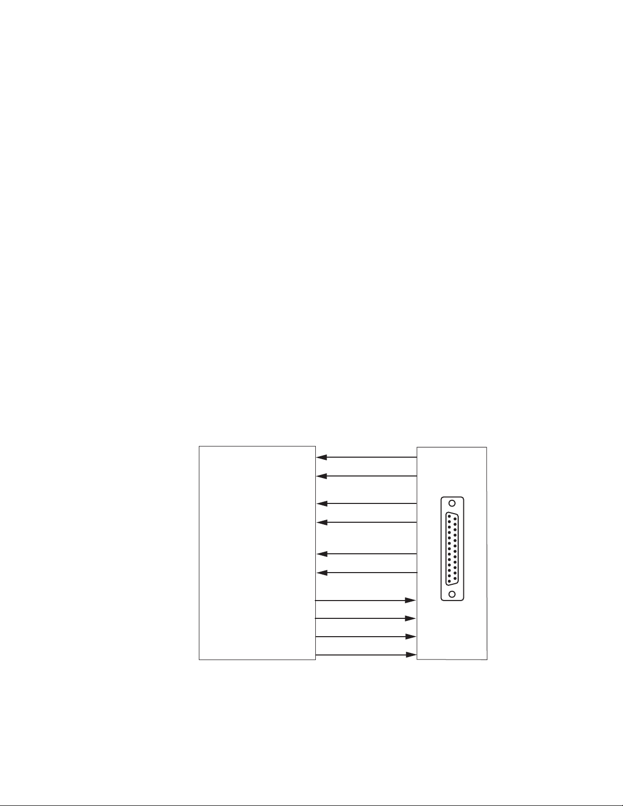
GPI Program Output Controls and Monitoring
The Program Output selection can be controlled through the SubD-25 GPI
I/O connection mounted on the rear module when wired to an external
customer-supplied GPI control device. Switching is activated by contact
closure. The GPI controls work directly on the front module to select the
Program Output. Primary, Secondary, and Alternate input signal status can
also be reported to the GPI interface through tally connections.
Configuration Summary
The four switching control lines from the customer-supplied device and the
six input status reporting lines from the front module are shown in
Figure 2.
Figure 2. GPI Interface
8972PX — Instruction Manual 13
Page 14

Configuration Summary
When the GPI Exclusive Control line is activated by contact closure, only
the Switch to Primary, Switch to Secondary, or Switch to Alternate GPI
control lines can be used to change the designated input selection (by
contact closure). The Program Output selection will be under control of the
GPI Switch commands until the GPI Exclusive Control is de-activated
leaving the module in Manual mode. At this point, the user may use
another manual switching control to change the input to the Program
Output or set the module to an Autonomous switching strategy.
It is not necessary to activate the GPI Exclusive Control to drive the module
with a GPI control. Any one of the three GPI controls (Switch to Primary,
Switch to Secondary, or Switch to Alternate) can be activated indepen
dently by contact closure forcing the Program Output to the designated
input. This also switches the module to Manual mode. The selection of the
Program Output will remain under GPI control only as long as one of these
three GPI controls is activated (by a contact closure).
While the Program Output selection is under GPI control, the web pages
will display a message stating
Figure 27 on page 64). Once GPI control is removed (no contact closure
(see
on any of the four GPI controls), the module is in Manual mode. The user
can then control the module with any of the manual switching controls (see
Manual Switching Controls on page 13) or set the module to an Autonomous
switch mode (Maintain Primary or Maintain Stability).
The GPI is controlling the Program Output Selection
-
Web Page Control
The Program Output can be forced manually using the Output Control web
page 62) by selecting the Force Primary, Force Secondary, or Force Alternate
page (
buttons in the Program Output Selection section,. This will change the
Switching Strategy Switch mode to the
page.
Newton Control Panel
The Newton Control Panel command PrgOutput allows manual selection of
the Primary, Secondary, or Alternate output and forces the Program output
to this selection. For a summary of all Newton Control Panel parameters,
refer to the
Summary of 8972PX Configuration Functions on page 83.
SNMP Commands
In addition to the standard 8900 module SNMP monitoring reporting, the
8972PX module allows two get/set commands to manually manage the
input selection (Input Select) and module mode of operation (Switchback
Strategy) through the SNMP interface. Refer to
Commands on page 80 for details.
Manual radio button on this web
Using Additional SNMP
14 8972PX — Instruction Manual
Page 15
Front Edge Pushbutton Controls
Force Alternate button
Force Secondary button
Force Primary button
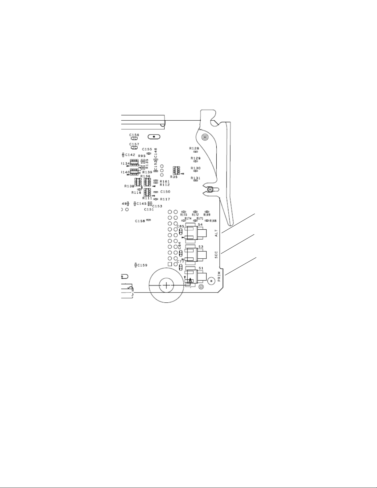
On the back of the front edge of the module circuit board (Figure 3) are
three pushbuttons labeled Prim (S1), Sec (3), and Alt (S4) that will manually
force the Program output to Primary, Secondary, or Alternate when acti
vated. Hold the button for at least 3 seconds for the change to take effect.
Figure 3. Front Edge Controls Manual Force Buttons
Configuration Summary
-
8972PX — Instruction Manual 15
Page 16

Configuration Summary
Autonomous Mode
When the module Switching Strategy is set for an autonomous mode, the
module automatically determines signal status based on enabled signal
health criteria as interpreted by the module for the three video inputs, Pri
mary, Secondary, and Alternate (when selected for usage in Autonomous
mode on the System Config web page). Refer to the block diagram in
Figure 4 on page 19 for an overview of the Autonomous mode.
There are two switching strategies in the Autonomous mode: Maintain Stability and Maintain Primary. One of these must be selected as the Switch
Mode for use in the Autonomous mode using one of the remote controls
(Output Control web page, Newton Control Panel, or SNMP get/set com
mands).
• Maintain Stability Mode – in situations where signal stability on the
program Output is most important, select this mode. When the Primary
has failed and has switched to the Secondary, it will stay on the selected
Secondary until forced back to the Primary manually or the Secondary
fails. This mode provides the least amount of signal interruption (the
most signal stability).
-
-
•
Maintain Primary Mode – in situations where it is favored to have the
Primary input active as much as possible, select this mode. When the
Primary has failed and has switched to the backup candidate, when the
Primary has recovered, the module automatically returns the Primary
to the Program Output. The switchback to the Primary can be set to a
delay to allow the restored signal to establish itself after recovery. The
amount of Program Switchback Delay is set by the user on the Output
Control web page or using the Newton Control Panel.
Signal Health Criteria
Signal health status for the three input signals is determined by certain criteria analyzed by the module. The 8972PX handles HD/SD SDI video
signals or DVB ASI signals and uses different criteria to determine signal
health status. The status of the module inputs (when
the I/O Config web page for each input signal) is given on every web page
in the header area at the top of the page and also reported on the Newton
Control Panel and can be read from the GPI interface.
The input format to the module can be selected as Auto allowing all of the
signal standards in the Input Standard Selection pulldown (on the
Config Web Page on page 55) to be considered valid by the module for any
input. If only a single standard is selected as the input format, only that
standard will be considered valid for any input to the module.
Reporting is enabled on
System
16 8972PX — Instruction Manual
Page 17

Configuration Summary
HD/SD Criteria
When the input signal is HD or SD SDI video, the signal health status is
based on the following criteria as analyzed by the module. These criteria
are always enabled and the module will determine module health by
checking each item below.
The signal is considered Good when:
• Carrier Detect – a valid carrier is detected on the input,
• Serial Lock – the serial receiver is locked to a SMPTE compliant data
stream,
• Valid Format – the input signal matches the selected input selection,
• SMPTE Presence – no instability has been detected for a valid format,
and
• No SMPTE TRS Errors – no TRS (Timing Reference Signal) errors have
been detected.
If any one of these criteria are incorrect for the input type selected, the
signal will be reported as
occur depending on the Switching Strategy Switch Mode selected in con
figuration:
Not Good. When this happens, the following cases
-
• If the Switchback Strategy Switch Mode is set for Maintain Primary, the
module will switch the Program Output immediately to the Backup
Candidate. It will return the Primary input to the Program Output as
soon as the Primary input becomes good again in the time set with the
Switchback Delay control on the Output Control web page or with the
Newton Control Panel.
• If the Switchback Strategy Switch Mode is set for
the Primary input is detected as
Program Output immediately to the next valid Backup Candidate and
remain there until the user decides to manually override the selection
to return the Primary input to the Program output or the Backup Candidate fails.
An optional criteria category to check for EDH/CRC errors can be enabled
by checking the EDH/CRC
The error detection process is done independently on each input channel
for both SMPTE
total of fields allowed before the signal is considered not good) can be
selected with the controls provided.
292M and SMPTE 259M. The error threshold (number and
Enable checkbox.
Not Good, the module will switch the
Maintain Stability, when
8972PX — Instruction Manual 17
Page 18

Configuration Summary
DVB ASI Criteria
When the input signal is DVB ASI, the signal health status is based on the
criteria described below as determined by the module. These criteria are
always enabled and the module will determine module health by checking
each item below.
The signal is considered Good when:
• Carrier Detect – a valid carrier is detected on the input,
• Serial Lock – the serial receiver is locked to a DVB ASI compliant data
stream,
• Valid Format – the input signal matches the selected input selection,
and
• MPEG2 TS Lock – the input signal is locked to the synchronization byte
of the MPEG packets.
If any one of the criteria are incorrect for the input type selected, the signal
will be reported as
the same as the HD/SD SDI video signals explained in
page 17.
Not Good. Switchback Strategy Switch Mode selection is
HD/SD Criteria on
On each input link, the bit rate of packets is evaluated on up to 4 userdefined PIDs (the minimum bit rate detected is one packet per second or
kbps). A PID is seen as not present as soon as there is no packet within
1.5
one second. It is recommended to choose PIDs whose bit rate is at least 4.5
kbps to avoid an unexpected switch of the input if packets are not evenly
spaced on the transport stream. Primary and Secondary inputs share the
same PIDs. The Alternate input can have 4 independent dedicated PIDs.
For setting the PIDs, see DVB/ASI Criteria Web Page on page 60. Presence
and Continuity Error reporting criteria can also be enabled as desired for
each PID stream.
18 8972PX — Instruction Manual
Page 19
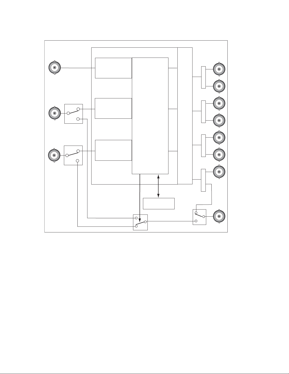
Figure 4. Autonomous Mode Block Diagram
8580_02r1
J10: Secondary
Input
J9: Primary
Input
J3: Output 1.2
J1: Output 1.1
J4: Output 2.2
J2: Output 2.1
J8: Output 3.2
J7: Program Output
Relay Protected
Output
J5: Program Output
Protected Program
Output
J6: Output 3.1
J11: Alternate
Input
Rear Module
Front Module
Programmable Output Pairs
HD/SD or DVB-ASI
Criteria Analysis
HD/SD or DVB-ASI
Criteria Analysis
HD/SD or DVB-ASI
Criteria Analysis
Manual Controls
Switch Manager
Configuration Summary
8972PX — Instruction Manual 19
Page 20

Configuration Summary
Switching Summary Tables
To aid in understanding the detailed processing behavior in the various
states of the module inputs, a number of switching summary tables are pro
vided in the next section. Use these tables along with the following three
basic rules for autonomous switching of inputs to the Program output to
better understand processing behavior:
1. The module always selects the Primary or Secondary inputs (when
valid) over the Alternate input.
2. In the Maintain Primary autonomous mode, the module always selects
the Primary input when it is valid.
3. In the Maintain Stability autonomous mode, the module always selects
the valid input that reduces the amount of switching. If it switches from
the Primary to the Secondary, it will leave the Secondary as the Program
output until the Secondary fails.
Ta bl e 1 through Tab le 5 present a detailed description of the next Program
output/Backup Candidate state by giving each possible case for the current
state of the Program output and the Backup Candidate using the Primary,
Secondary, and Alternate inputs and other configuration factors.
-
Ta bl e 1 through Tab le 5 include the following:
• Program = Primary/Backup = Secondary Tabl e 1 o n pa ge 22
• Program = Secondary/Backup = Primary Tab le 2 on p age 22
• Program = Alternate/Backup = Primary Table 3 on page 23
• Program = Primary/Backup = Alternate Table 4 on page 23
• Program = Secondary/Backup = Alternate Table 5 on page 24
Ta bl e 6 on page 25 provides a graphical summary of the various states of
the Program Output. Refer to the explanation of this table in Protect Switch
Summary Table on page 24.
20 8972PX — Instruction Manual
Page 21

Next State Program/Backup Tables
Ta bl e 1 through Tab le 5 are arranged from left to right to with the items
listed below. Abbreviations for the input signals are: Primary (PRI), Secondary (SEC) and Alternate (ALT).
• Current Program – lists the input currently on the Program Output.
• Current Backup – lists the Backup Candidate that will replace the
current input on the Program Output if it fails.
Configuration Summary
• Alternate Enabled – indicates
for use in Autonomous mode and
• Maintain Primary – indicates
Autonomous mode,
mode does not matter.
• Primary Status – the status of the Primary input is
mode does not matter.
• Secondary Status – the status of the Secondary input is
if the mode does not matter.
• Alternate Status – the status of the Alternate is
mode does not matter.
• Action of Program Output/Backup – shows the switch action of the
Program output and the Backup Candidate.
• Next Program/Next Backup Candidate – summarizes what the next
Program output will be and the next Backup Candidate using the input
signal abbreviations.
No if Maintain Stability is enabled, or N/A if the
Yes when the Alternate input is enabled
No when it is not enabled.
Yes if Maintain Primary is enabled as the
Good, Fail, or N/A if the
Good, Fail, or N/A
Good, Fail, or N/A if the
8972PX — Instruction Manual 21
Page 22

Configuration Summary
Current
Program
PRI SEC No N/A
PRI SEC Yes N/A
Current
Backup
Alternate
Enabled
Table 1. Program = Primary/Backup = Secondary
Maintain
Primary
Primary
Status
Good N/A N/A No Action PRI_SEC
Fail Good N/A Switch_SEC, Switch_PRI SEC_PRI
Fail Fail N/A No Action PRI_SEC
Good Good N/A No Action PRI_SEC
Good Fail Good Stay_PRI, Switch_ALT PRI_ALT
Good Fail Fail No Action PRI_SEC
Fail Good Good Switch_SEC, Switch_ALT SEC_ALT
Fail Good Fail Switch_SEC, Switch_PRI SEC_PRI
Fail Fail Good Switch_ALT, Switch_PRI ALT_PRI
Fail Fail Fail No Action PRI_SEC
Secondary
Status
Alternate
Status
Action of
Program Output/
Backup Candidate
Next Program/
Next Backup
Current
Program
SEC PRI No
SEC PRI Yes
Current
Backup
Alternate
Enabled
Table 2. Program = Secondary/Backup = Primary
Maintain
Primary
No Good
Yes Good N/A N/A Switch_PRI, Switch_SEC PRI_SEC
N/A Fail N/A N/A No Action SEC_PRI
No Good
Yes Good
N/A Fail
Primary
Status
Secondary
Status
Good N/A No Action SEC_PRI
Fail N/A Switch_PRI, Switch_SEC PRI_SEC
Good N/A No Action SEC_PRI
Fail Good Switch_PRI, Switch_ALT PRI_ALT
Fail Fail Switch_PRI, Switch_SEC PRI_SEC
Good N/A Switch_PRI, Switch_SEC PRI_SEC
Fail Good Switch_PRI, Switch_ALT PRI_ALT
Fail Fail Switch_PRI, Switch_SEC PRI_SEC
Good Good Stay_SEC, Switch_ALT SEC_ALT
Good Fail No Action SEC_PRI
Fail Good Switch_ALT, Switch_PRI ALT_PRI
Fail Fail No Action SEC_PRI
Alternate
Status
Action of
Program Output/
Backup Candidate
Next Program/
Next Backup
22 8972PX — Instruction Manual
Page 23

Table 3. Program = Alternate/Backup = Primary
Current
Program
ALT PRI No N/A
ALT PRI Yes N/A
Current
Backup
Alternate
Enabled
Maintain
Primary
Configuration Summary
Primary
Status
Good N/A N/A Switch_PRI, Switch_SEC PRI_SEC
Fail Good N/A Switch_SEC, Switch_PRI SEC_PRI
Fail Fail N/A Switch_PRI, Switch_SEC PRI_SEC
Good Good N/A Switch_PRI, Switch_SEC PRI_SEC
Good Fail Good Switch_PRI, Switch_ALT PRI_ALT
Good Fail Fail Switch_PRI, Switch_SEC PRI_SEC
Fail Good Good Switch_SEC, Switch_ALT SEC_ALT
Fail Good Fail Switch_SEC, Switch_PRI SEC_PRI
Fail Fail Good No Action ALT_PRI
Fail Fail Fail Switch_PRI, Switch_SEC PRI_SEC
Secondary
Status
Alternate
Status
Action of
Program Output/
Backup Candidate
Next Program/
Next Backup
Table 4. Program = Primary/Backup = Alternate
Current
Program
PRI ALT No N/A
PRI ALT Yes N/A
Current
Backup
Alternate
Enabled
Maintain
Primary
Primary
Status
Good N/A N/A Switch_PRI, Switch_SEC PRI_SEC
Good Good N/A Stay_PRI, Switch_SEC PRI_SEC
Good Fail Good No Action PRI_ALT
Good Fail Fail Stay_PRI, Switch_SEC PRI_SEC
Secondary
Status
Fail Good N/A Switch_SEC, Switch_PRI SEC_PRI
Fail Fail N/A Switch_PRI, Switch_SEC PRI_SEC
Fail Good Good Switch_SEC, Stay_ALT SEC_ALT
Fail Good Fail Switch_SEC, Switch_PRI SEC_PRI
Fail Fail Good Switch_ALT, Switch_PRI ALT_PRI
Fail Fail Fail Stay_PRI, Switch_SEC PRI_SEC
Alternate
Status
Action of
Program Output/
Backup Candidate
Next Program/
Next Backup
8972PX — Instruction Manual 23
Page 24

Configuration Summary
Current
Program
SEC ALT No
SEC ALT Yes
Current
Backup
Alternate
Enabled
Table 5. Current State SEC_ALT
Maintain
Primary
No Good
Yes Good N/A N/A Switch_PRI, Switch_SEC PRI_SEC
N/A Fail N/A N/A Stay_SEC, Switch_PRI SEC_PRI
No Good
Yes Good
N/A Fail
Primary
Status
Secondary
Status
Good N/A Stay_SEC, Switch_PRI SEC_PRI
Fail N/A Switch_PRI, Switch_SEC PRI_SEC
Good N/A Stay_SEC, Switch_PRI SEC_PRI
Fail Good Switch_PRI, Stay_ALT PRI_ALT
Fail Fail Switch_PRI, Switch_SEC PRI_SEC
Good N/A Switch_PRI, Switch_SEC PRI_SEC
Fail Good Switch_PRI, Stay_ALT PRI_ALT
Fail Fail Switch_PRI, Switch_SEC PRI_SEC
Good Good No Action SEC_ALT
Good Fail Stay_SEC, Switch_PRI SEC_PRI
Fail Good Switch_ALT, Switch_PRI ALT_PRI
Fail Fail Stay_SEC, Switch_PRI SEC_PRI
Alternate
Status
Action of
Program Output/
Backup Candidate
Next Program/
Next Backup
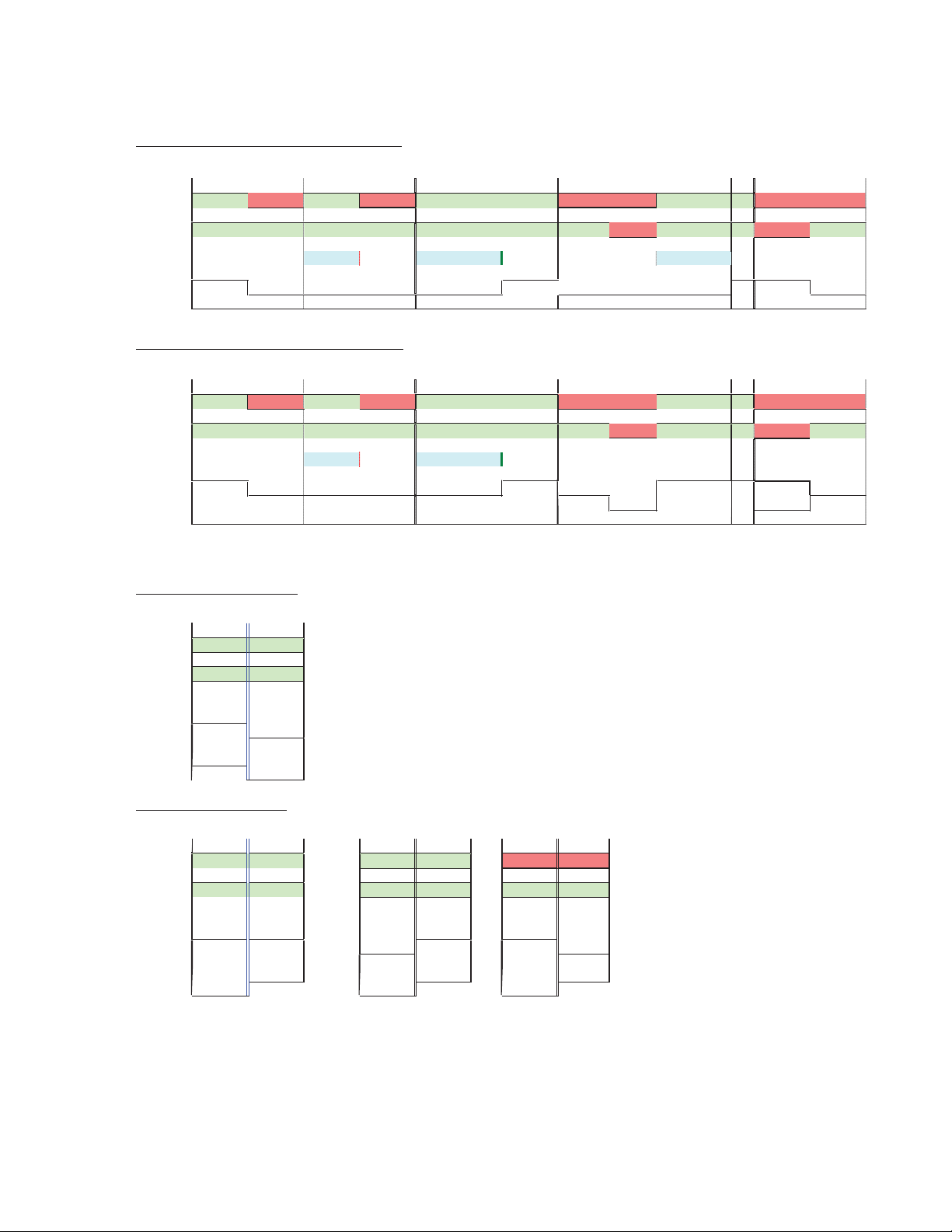
Protect Switch Summary Table
Ta bl e 6 on page 25 gives a graphical representation of the Program output
in the following states:
• Autonomous Mode Primary First (w/o Alternate) – the top graphic
gives the status of the Output (Out) for the most useful/common states
of the Primary (PRI), and Secondary (SEC) inputs, including the Timer
(Switchback Delay), with the Autonomous mode enabled. The Alternate is not used in this example.
• Autonomous Mode Primary First (with Alternate) – the second graphic
gives the status of the Output (Out) for the most useful/common states
of the Primary (PRI), Secondary (SEC), and Alternate (ALT) inputs,
including the Timer (Switchback Delay), with the Autonomous mode
enabled.
• Force Switch to Secondary – this graphic illustrates the state of the
output when the Secondary is forced manually to the output. Note that
the Autonomous mode switches to Manual. The Autonomous mode
must be re-enabled using the Output Control web page, The Newton
Control Panel or the SNMP controls.
• Switch to Maintain Primary – this graphic shows the state of the output
when the mode is changed from Manual to Autonomous when the
Primary is good and when the Primary is bad.
24 8972PX — Instruction Manual
Page 25
Autonomous Mode Primary First (w/o Alternate)
PRI fails
PRI restored
too short PRI restored
PRI Fails
then SEC fails
PRI & SEC Fail
SEC recovers first
PRI OK Fail OK Fail
OK
OK OK Fail Fail OK OK
Fail
Fail
SEC OK OK OK OK
OK
OK OK OK Fail OK OK Fail OK
Timer
Timer
Timer OK Timer OK
Output
PRI SEC
SEC
SEC
PRI PRI
SEC SEC SEC PRI SEC
On On On On On On On
On On
On On On
Autonomous Mode Primary First (with Alternate)
PRI fails
PRI restored
too short
PRI restored
PRI Fails
then SEC fails
PRI & SEC Fail
SEC recovers first
PRI OK Fail OK Fail
OK
OK OK
Fail Fail
OKOK
Fail
Fail
SEC OK OK OK
OK OK
OK
OK OK Fail
OK OK
Fail OK
Timer
Timer Timer OK
Output
PRI SEC SEC SEC SEC PRI SEC PRI SEC
ALT
ALT
Autonomous
Autonomous
Autonomous
Autonomous
On On On On On On
On
On On
On On On
Forced Switch to Secondary
Force to SEC
PRI OK
OK
SEC OK
OK
Output
PRI SEC
PRI
SEC
Output
On Off
Switch to Maintain Primary
PRI is OK PRI is OK
start with PRI start with SEC
PRI is Bad
start with PRI
OK OK OK
OK
Fail Fail
OK
OK OK OK OK OK
PRI
PRI
SEC PRI
PRI
SEC
Off On
Off On Off On
8580_08r0
Table 6. Protect Switch Summary Table
Configuration Summary
8972PX — Instruction Manual 25
Page 26

Configuration Summary
Passive Bypass Only Mode
The Passive Bypass Only mode has two main purposes as described below:
1. During normal operation, the Bypass mode for the module is set for
Active Processing Enabled on the System Config web page. The module can
be set for
that occurs when power is lost or the front module is removed. The
Passive Bypass Only mode is normally used for maintenance purposes
such as cabling or testing the rear module relay bypass path.
When set for Passive Bypass Only, the module simulates the bypass state
where the Primary and Secondary inputs are switched by relays on the
rear module to the Relay-Protected Program Output at BNC, J7 as
shown in
signals now bypass the front module completely and the Status of the
Primary and Secondary inputs on all web page headers are reported as
Bypassed as shown in the example in (Figure 22 on page 56). As this
mode is only a simulation of removing the front module, putting the
module in this mode does not affect the other controls on the front
module or the Alternate input.
Passive Bypass Only to simulate the relay-protected bypass state
Figure 5 on page 27. The Primary and Secondary input
In this mode, output J7 (Relay-Protected Program Output), remains the
input previously selected (except if it was the Alternate input it will be
switched to the Primary input). When the module is switched back to
Active Processing Enabled on the System Config web page, it returns in
Manual mode with no change to the Program Output.
2. When power is lost to the frame or the front module is completely
removed, the relay-protected Primary and Secondary inputs will
automatically be switched to the rear module relay bypass path and the
input previously selected will be latched to the output at BNC J7, the
Relay-Protected Program Output. The passive bypass path ensures the
continuous transmission of the Primary/Secondary input signal to the
Relay-Protected Program Output. When power is returned to the frame
or the module is reinserted, the module will be in Manual mode with
no change to the Program Output.
26 8972PX — Instruction Manual
Page 27
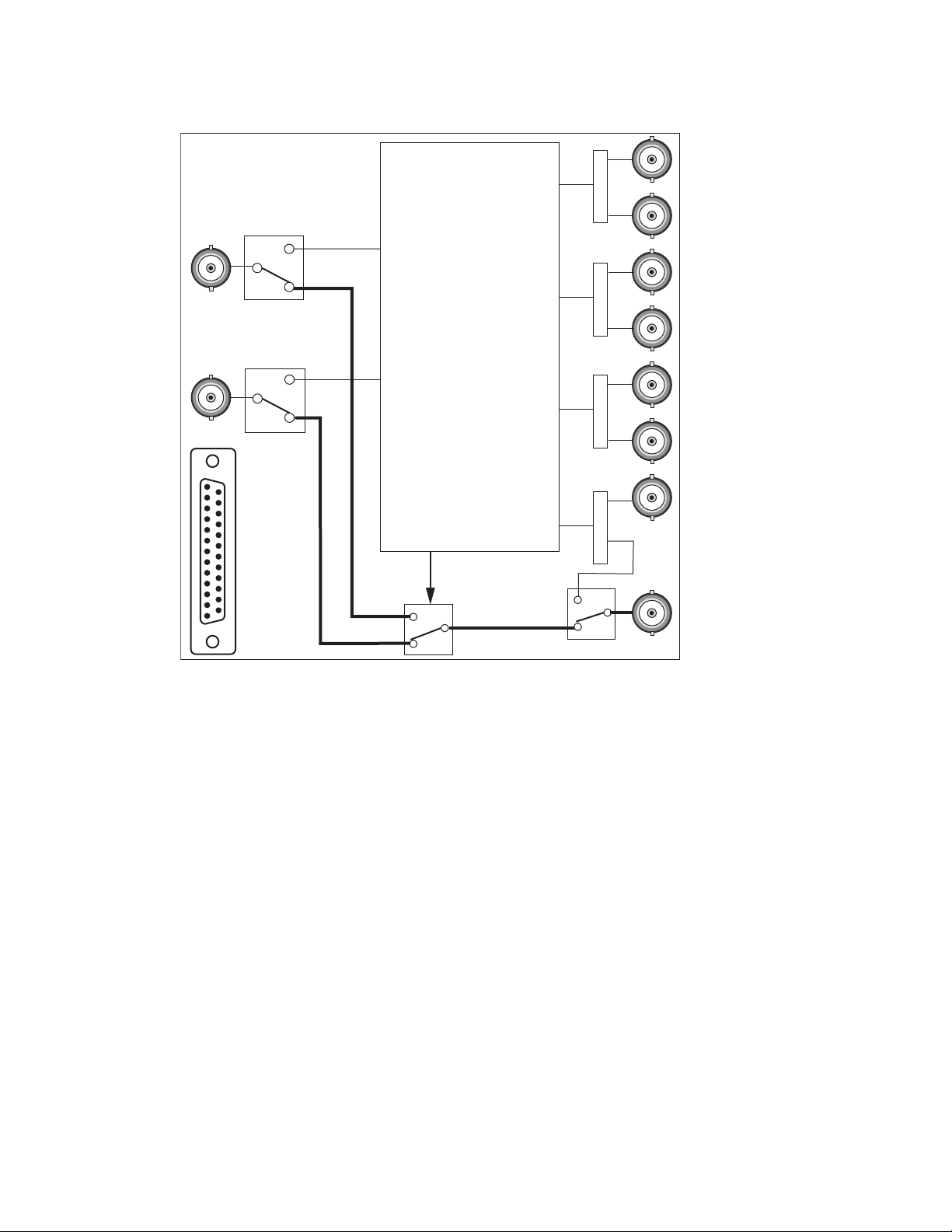
Figure 5. Module in Passive Bypass Mode
8580_04r1
GPI I/O
J10: Secondary Input
J9: Primary Input
J7: Program Output
Relay Protected Program Output
Primary and Secondary
signals bypass the
front module
Configuration Summary
8972PX — Instruction Manual 27
Page 28

Installation
Installation
Module Placement in the GeckoFlex Frame
The 8972PX model consists of a front and dual rear module set that can only
be installed in a GeckoFlex frame.
Installation of the 8972PX module set is a process of:
1. Placing the 8900PX-DR dual rear module in a rear frame slot (this rear
module requires two adjacent rear slot spaces and cannot be installed
in Slot 10),
2. Placing the front module in the corresponding front slot
(corresponding to the module connector on the rear module), and
3. Cabling the signal ports.
All GeckoFlex front and rear modules can be inserted and removed from a
GeckoFlex frame with power on.
There are ten front and rear cell locations in the 2 RU GeckoFlex frame
Figure 6) to accommodate either audio, analog and digital video modules.
(
The 8972PX module set uses the 8900PX-DR rear module that requires two
adjacent slots, allowing up to five 8972PX modules per frame.
Figure 6. GeckoFlex Frame
28 8972PX — Instruction Manual
Page 29

Module Installation Precautions
Please read and follow the precautions listed below before installing the
front and rear modules:
• Use standard anti-static procedures during installation. As modules
can be installed or removed when the GeckoFlex frame is powered up,
before removing the cover, please use an anti-static bracelet or heel
strap tied to a metal part of the frame.
• Install the rear module first, then the front module.
• When installing or removing a rear module, loosen or tighten the
screws holding the retainer clips to the frame manually with the
retainer clip tool provided inside the front cover of the frame or use a
2 mm (5/64”) hex screwdriver. Please do not use an electric screwdriver.
Note On newer 751- version GeckoFlex frames, a Rear Retainer Clip removal tool
and 2 extra retainer clips and screws for installing them are provided on the
inside of the frame cover.
Installation
• Make every effort to leave the screws holding the retainer clips in place
(do not remove them completely). They are very small and can easily
drop into other equipment causing a shorting hazard. (Two turns of the
screw should be enough to loosen the screws, 3 turns or more will
remove it.)
• When installing a rear module, tighten the screws on the retainer clips
just until snug. Do not apply more force than is necessary to seat the
rear module. The recommended torque specification is
4-5 inch-lbs/0.45-0.6Nm.
8972PX — Instruction Manual 29
Page 30

Installation
Use needlenose pliers
to pull out blank after
removing retainer clips.
Rear Module Installation
Each 8900PX-DR rear module requires two adjacent rear frame slots, so the
front module cannot be installed in slot 10 of the frame. Each rear module
or blank rear adapter cover is held in place by two retainer clips as shown
in
Figure 7. To install a rear module into the frame, follow these steps:
1. Loosen (but do not remove completely) the two screws holding each
retainer clip to the frame with a 2 mm (5/64”) hex screwdriver. Pull up
on the retainer clip to remove it, leaving the screws in place.
CAUTION Be careful to leave the screws in place as they can be easily lost or fall into
equipment below the frame creating a shorting hazard.
2. Remove the blank rear adapter covers on two adjacent slots by inserting
needlenose pliers into the slots in the top and bottom of the blank and
pulling it off.
Note To remove a rear module already installed, follow the same steps. It is helpful
to first remove the front module so the rear can be pulled out more easily.
3. Insert the rear module into the empty slots.
4. Replace each retainer clip over the two screws on both sides of the
module and push down to seat the retainer.
5. Tighten the screws for each retainer clip just until they are snug. Do not
force or torque the screws too tightly.
Figure 7. Installing Rear Module
30 8972PX — Instruction Manual
Page 31

Front Module Installation
8431_07
Slide top and bottom card carriers on module
over top and bottom guides on right of slot.
Module installed
Locking Pin
Card Carriers
Card Carriers
Front Module Side View
After installing the dual rear module, install the front module in the corresponding front slot as follows:
1. Remove the front cover of the frame.
2. Locate the two front slots that correspond to the two rear slots where
the rear module has been installed.
3. Slide the module into the slot on the left so that the plastic card guides
on the module top and bottom edges go over the upper and lower
raised rail guides of the slot and the module connector mates with the
rear module connector (Figure 8).
4. Carefully slide the module into the rear connector.
5. Lock the front module ejector tab into the locking pin.
6. Install the front cover of the frame during normal operation.
Figure 8. Front Module Installation
Installation
8972PX — Instruction Manual 31
Page 32

Installation
J10: Secondary Input
8972PX Module
J9: Primary Input
J7: Program Output
Relay Protected
Program Output
Cable Length A
Cable Length A + Cable Length B = Total Cable Length
Cable Length B
8580_03
Signal Source
Destination
Equipment
Cabling
Cabling is done on the rear of the 8900PX-DR rear module illustrated in
Figure 10 on page 33. Inputs and outputs are also illustrated on the I/0
Config web page (I/O Config Web Page on page 52). Pinouts for the SubD-25
GPI I/O connector are given in Tab le 7 on page 35.
Output pairs Output 1.1 and 1.2, Output 2.1 and 2.1, and Output 3.1 and 3.2
are user-configurable to output different signals as desired. For configura
tion information, refer to Configuration Summary on page 11.
Before cabling the module, read the following section on determining cable
length.
Determining Maximum Cable Length
To maintain the quality of the Program Output signal when the front
module is bypassed in the case of loss of power or front module removal,
the total cable length must be determined in Passive Bypass mode. The
total cable length is defined as the addition of the cable length from the
signal source to the 8972PX Primary (J9) or Secondary input (J10) plus the
cable length from the 8972PX output BNC J7 to the destination equipment
as shown in
in SD and 100m in HD. Refer to Tab le 9 on page 71 for a list of specifications.
When cabling the module, you can test cable length and the quality of the
bypassed Program Output signal by setting the Bypass Mode on the
System Config web page to Passive Bypass Only (see
the module and monitoring the Program Output signal on J7 (Relay-Protected Program Output).
Figure 9. This cable length is specified as no more than 300m
-
page 55) or removing
Figure 9. Total Cable Length Illustration
32 8972PX — Instruction Manual
Page 33

Figure 10. 8900PX-DR Rear Module
8900PX-DR
J1 J2
J3 J4
J5 J6
J7
J9 J10
J11
GPI I/O
J8
J2: Output 2.1
J4: Output 2.2
J6: Output 3.1
J8: Output 3.2
J10: Secondary Input
J9: Primary Input
J7: Relay Protected
Program Output
J5: Program
Output
J3: Output 1.2 J3: Output 1.2
J1: Output 1.1
J11: Alternate Input
Installation
Primary Input
Connect the Primary input signal to BNC J9.
Secondary Input
Connect the Secondary input signal to BNC J10.
Alternate Input
If using an Alternate input signal, connect it to BNC J11.
To include this Alternate input as a backup candidate for use in the autonomous switching mode, it must be enabled on the System Config web page
Alternate Input Usage in Autonomous Switch Mode control (see System Config
in the
Web Page on page 55).
To monitor the status of this input, Alternate Reporting must be enabled on
the I/O Config web page (
page 52).
8972PX — Instruction Manual 33
Page 34

Installation
Relay-Protected Program Output
The Relay-Protected Program Output at BNC J7 is the main Program
Output for the module. It wired to the relay-protected passive bypass cir
cuitry on the rear module which includes the Primary and Secondary
inputs as part of the relay path, assuring a continuous output source. Refer
to
Passive Bypass Only Mode on page 26 for an explanation of the bypass
mode.
Note To assure the bypassed Program Output signal meets the correct specifica-
tions, read the section on determining cable length in Determining Maximum
Cable Length on page 32.
Program Output
The Program Output at BNC J5 outputs the current Program Output signal
from BNC J7, the Relay-Protected Program output, when the module is not
in bypass mode. In bypass mode, the output at J5 is not active.
Outputs 1.1 and 1.2, Outputs 2.1 and 2.2, Outputs 3.1 and 3.2
-
Three sets of programmable output pairs (Outputs 1.1 and 1.2, Outputs 2.1
and 2.2 and Outputs 3.1 and 3.2) can be configured to output the Program,
Backup Candidate, Primary Input, Secondary Input, or Alternate Input
signal as desired. Programming of these output pairs is done on the Output
Control web page (
Newton Control Panel (see Tab le 12 on page 83).
GPI I/O Connector
The Program Output from the front module can be controlled and monitored through the SubD-25 GPI I/O connector on the rear module using an
external customer-supplied GPI interface. Due to the densely populated
rear module, a custom designed optional SubD-25 connector (8900PX-DBS)
is available from the factory in order to allow space for using a trumpeter
tool for connecting signals to adjacent BNCs (see
Option on page 35).
For using a standard SubD-25 connector, the following maximum dimensions are recommended:
• Maximum width of 15 mm
• Maximum length of 57 mm
Output Control Web Page on page 62) or using the
8900PX-DBS Connector
34 8972PX — Instruction Manual
Page 35

Installation
Pin 1
Pin 13
Pin 14
Pin 25
D-25 Female
8900PX-DBS Connector Option
A SubD-25 connector option (8900PX-DBS) may be purchased from the
factory that is ideal for use on the densely populated rear module. This con
nector and its dimensions are shown in Figure 11.
Figure 11. 8900PX-DBS SubD-25 Connector Option Dimensions
-
Connector Pinouts
Pinouts for the SubD-25 pin connector, GPI I/O, are given in Tab le 7. These
inputs and output assignments are hard-wired and may not be changed.
Typical wiring diagrams and more wiring details are given in
Control Interface on page 36 and GPI Relay Status Monitoring on page 39.
Table 7. GPI I/O Connector Pinouts
GPI I/O Pin Function Pin Function
1 GPI OUT Secondary Fail 14 GPI IN Switch to Primary
2 GPI OUT Primary is the Active Link 15 GPI IN Switch to Secondary
3 GPI OUT Secondary is the Active Link 16 GPI Exclusive Control Enable
4 GPI OUT Common Fail 17 Do not use (Reserved for future use)
5 GPI OUT Common Active 18 GPI OUT Primary Fail
6 Do not use (Reserved for future use) 19 GPI IN Switch to Alternate
7 Do not use (Reserved for future use) 20 GPI OUT Alternate Fail
8 Do not use (Reserved for future use) 21 GPI OUT Alternate Fail Common
9 Do not use (Reserved for future us)e 22 GPI OUT Alternate is Active Link
10 Do not use (Reserved for future use) 23 GPI OUT Alternate Active Link Common
11 Do not use (Reserved for future use) 24 Do not use (Reserved for future use)
12 Do not use (Reserved for future use) 25 Do not use (Reserved for future use)
GPI I/O
13 GPI In Common Ground
8972PX — Instruction Manual 35
Page 36

Installation
GPI I/O Control Interface
The GPI I/O connector inputs provide a means to enable (Force) the Primary, Secondary, or Alternate input signal to become the Program Output.
The inputs are suitable for a connection to a relay contact (switch button) or
to an open collector output in a typical circuit.
When the GPI Exclusive Control is activated, the Program Output can only
be changed using one of the Switch to Primary, Switch to Secondary, or
Switch to Alternate GPI controls until all GPI controls are de-activated.
To activate a GPI In function, a switch closure must be provided between
the GPI In common ground (pin 13) and the GPI In function for a minimum
of 80ms. To change states (deactivate the selected input) the contact closure
must be open for at least an 80ms duration.
Refer to Tab le 7 on page 35 for a complete list of the GPI I/O function pin
numbers. An example of a GPI interface using relay contacts is shown in
Figure 12. A typical Open Collector example is shown in Figure 13 on
page 38.
Note Use either Open Collector or relay (switch button) controls but not both
methods in the same GPI interface configuration.
36 8972PX — Instruction Manual
Page 37

Figure 12. GPI Input I/O Typical Circuit Using Relays
GPI
Exclusive
Control
2.21k ohm
4.75k ohm
Front Module
Rear Module:
GPI In 25-pin
Connector
Pin Numbers
16
GPI In
Switch to
Primary
14
+12V +3.3V
0.1uF
GPI_EX_CNT
GPI_SW_P
GPI In Typical
GPI In Typical
GPI In
Switch to
Secondary
GPI In
Common Gnd
GPI_SW_S
GPI In Typical
GPI In
Switch to
Alternate
GPI_SW_ALT
GPI In Typical
8580_07r1
15
19
13
Installation
8972PX — Instruction Manual 37
Page 38

Installation
Figure 13. GPI Input I/O Typical Circuit Using Open Collector
Front Module
+12V +3.3V
0.1uF
4.75k ohm
GPI
Exclusive
Control
GPI In
Switch to
Primary
GPI In
Switch to
Secondary
GPI In
Switch to
Alternate
Rear Module:
GPI In 25-pin
Pin Numbers
Open
Collector
Open
Collector
Open
Collector
Open
Collector
Connector
16
14
15
19
13
GPI In
Common Gnd
GPI_EX_CNT
2.21k ohm
GPI In Typical
GPI_SW_P
GPI In Typical
GPI_SW_S
GPI In Typical
GPI_SW_ALT
GPI In Typical
8580_05r1
38 8972PX — Instruction Manual
Page 39

Installation
GPI Relay Status Monitoring
The rear module GPI I/O connector also provides tally connections to
report to the external GPI device the input signal status of what input signal
is currently on the Program output and if any of the input signals have
failed. The Program output active and failure reporting status of the Pri
mary, Secondary, and Alternate inputs can be monitored by the GPI device.
The solid state relays are bi-directional; either polarity voltage can be
applied. It can be used to drive downstream DC relays. Each tally output is
active on a steady closure state.
Examples are given in Figure 14 on page 40 for both logic connections and
12V lamps to an external system. Refer to Tab le 7 on page 35 for a complete
list of GPI function pin numbers.
Relay outputs specifications are maximum current of 0.5A (continuous) or
1.5A peak (100 ms), 60V peak load voltage.
-
8972PX — Instruction Manual 39
Page 40

Installation
402 ohm
Front Module
Rear Module:
GPI I/O 25-pin
Connector
Pin Numbers
GPO_PRIMARY_IS_ACTIVE
GPO_PRIMARY_FAIL
+3.3V
0.1uF
GPO_P_ACTIVE
8580_06r0
2
3
402 ohm
GPO_SECONDARY_IS_ACTIVE
GPO_COMMON_ACTIVE
+3.3V
+3.3V
0.1uF
GPO_S_ACTIVE
22
402 ohm
GPO_ALTERNATE_IS_ACTIVE
0.1uF
GPO_ALT_ACTIVE
5
23
GPI Out Typical
GPI Out Typical
Logic
Logic
Logic
18
GPO_ALTERNATE_FAIL
20
GPO_SECONDARY_FAIL
+12V
1A
1
GPO_COMMON_FAIL
+12V
0.5A
4
GPO_ALTERNATE_FAIL_COMMON
21
GPO_ALTERNATE_ACTIVE_COMMON
Lamp
Lamp
Lamp
Figure 14. GPI Output I/O Typical Circuit
40 8972PX — Instruction Manual
Page 41

Power Up
Local/Remote Jumper
Operation Indicator LEDs
Power Up
The front LED indicators and configuration switches are illustrated in
Figure 15. Upon power-up, the green PWR LED should light and the
yellow CONF LED should illuminate for a few seconds for the duration of
module initialization.
Note When a media module is first plugged into a GeckoFlex frame, the 8900NET
module (if present) may report a momentary fault. This will clear once the
media module has booted up.
With factory default configuration and valid Primary, Secondary and Alternate input signals connected, the PWR LED, the SEL LED indicating the
active Program output source, and the PRES LEDs for valid input signals
on the top side of the module front edge should illuminate (
Refer to Tab le 8 on page 42 to see the operating indicator combinations.
Figure 15).
Local/Remote Jumper
The on-board Local/Remote jumper, J8, (Figure 15) is set by default at the
factory to the LOC/REM position (pins 1-2). This setting allows access to
both the local and remote controls. Remote controls include the web inter
face, Newton Control Panel, and SNMP commands used for setting
module configuration parameters. It is possible to lock out remote controls
by moving the jumper to Local control only (LOC position, pins 2-3).
Figure 15. Front Panel LED Indicators
-
8972PX — Instruction Manual 41
Page 42

Power Up
Table 8. Front Board Edge LED Names and Meaning
LED Indication Condition
Off Normal operation.
On continuously Module has detected an internal fault.
Flashing Indicates a warning condition. All possible warnings are listed in Table 10 on page 76.
Off No activity on frame communication bus.
3 Quick Pulses Locate Module command received by the module from a remote control system.
Short flash Activity present on the frame communication bus.
Off Module is in normal operating mode.
3 Quick Pulses Locate Module command received by the module from a remote control system.
On continuously Module is initializing, changing operating modes or programming hardware.
Off No power to module or module’s DC/DC converter failed.
On continuously Normal operation, module is powered.
Off Alternate input is not selected as the Program output.
On Alternate input is selected as the Program output.
Off No valid signal is detected on the Alternate input BNC.
On Valid signal is detected on the Alternate input BNC.
Off Alternate input signal is detected as good.
On Alternate input signal is detected as not good.
Off Primary input is not selected as the Program output.
On Primary input is selected as the Program output.
Off No valid signal is detected on the Primary input BNC.
On Valid signal is detected on the Primary input BNC.
Off Primary input signal is detected as good.
On Primary input signal is detected as not good.
Off Secondary input is not selected as the Program output.
On Secondary input is selected as the Program output.
Off No valid signal is detected on the Secondary input BNC.
On Valid signal is detected on the Secondary input BNC.
Off Secondary input signal is detected as good.
On Secondary input signal is detected as not good.
Off GPI input is not active.
On GPI input is active.
ALT
PRI
SEC
FAULT
(red)
COMM
(yellow)
CONF
(yellow)
PWR
(green)
SEL
(green)
PRES
(green)
FAIL
(yellow)
SEL
(green)
PRES
(green)
FAIL
(yellow)
SEL
(green)
PRES
(green)
FAIL
(yellow)
GPI
(yellow)
42 8972PX — Instruction Manual
Page 43

Configuration
Module Configuration and Monitoring
Configuration
The 8972PX module configuration operating parameters are set using the
web pages and the Newton Control Panel which require the presence of the
8900NET (Net Card) Network Interface module.
Refer to the following sections for configuration instructions:
• Module Configuration and Monitoring (below)
• Configuration Summary Table (page 83)
8972PX module configuration and monitoring is performed using a web
browser GUI interface or a networked Newton Control Panel when the
8900NET Network Interface module is present in the GeckoFlex frame.
Each of these interfaces is described below. In addition, monitoring of
signal status can be done with the GPI interface and an SNMP application.
8900NET Module Information
Refer to the 8900NET Network Interface Module Instruction Manual for information on the 8900NET Network Interface module and setting up and
operating the GeckoFlex frame network.
Note The 8900NET module in the GeckoFlex frame must be running software
version 4.2.0 or higher for proper remote and control panel operation.
Upgrade software and instructions for the 8900NET can be downloaded from
the Grass Valley web site. See System Requirements on page 10.
Newton Control Panel Configuration
A Newton Control Panel (hard and/or soft version) can be interfaced to the
GeckoFlex frame over the local network. Refer to the documentation that
accompanies the Newton Modular Control System for installation, config
uration, and operation information.
Control panel access offers the following considerations for module configuration and monitoring:
• Ability to separate system level tasks from operation ones, minimizing
the potential for on-air mistakes.
• Ability to group modular products—regardless of their physical locations—into logical groups (channels) that you can easily manipulate
with user-configured knobs.
-
• Update software for applicable modules and assign frame and panel IP
addresses with the NetConfig Networking application.
8972PX — Instruction Manual 43
Page 44

Configuration
• Recommended for real-time control of module configuration parameters, providing the fastest response time.
Note Not all module functions are available with the control panel, such as E-MEM
and factory default recalls. The available control panel controls for the
8972PX module are listed in Table 12 on page 83.
An example of the Newton Configurator is shown in Figure 16.
Figure 16. Newton Configurator Example
Web Browser Interface
The web browser interface provides a graphical representation of module
configuration and monitoring.
Use of the web interface offers the following considerations:
• Provides complete access to all module status and configuration functions, including naming of inputs and outputs, factory parameter and
name default recalls, E-MEM functions, slot configuration, and SNMP
monitoring controls.
• Web access will require some normal network time delays for processing of information.
• Configuration parameter changes may require pressing
Enter, upload processing time, and a manual screen refresh to become
effective.
Apply button or
• Web interface recommended for setting up module signal and slot
names, E-MEMS, and reporting status for SNMP and monitoring.
44 8972PX — Instruction Manual
Page 45

Configuration
The Links section lists the frame and its current modules. The selected link's Status
page is first displayed and the sub-list of links for the selection is opened. The sub-list
allows you to select a particular information page for the selected device.
Content display section
displays the information page
for the selected frame or module (frame slot icons are also
active links).
Refresh button for manual
update of page
8480_02r1
Refer to the Frame Status page shown in Figure 17. The modules can be
addressed by clicking either on a specific module icon in the frame status
display or on a module name or slot number in the link list on the left.
Note The physical appearance of the menu displays on the web pages shown in
this manual represent the use of a particular platform, browser and version
of 8900NET (Net Card) module software. They are provided for reference
only. Displays will differ depending on the type of platform and browser you
are using and the version of the 8900NET software installed in your system.
This manual reflects 8900NET software version 4.3.0, the latest release,
using Internet Explorer, the recommended web browser, with Windows XP
operating system.
For information on status and fault monitoring and reporting shown on the
Status page, refer to
Figure 17. GeckoFlex Frame Status Page
Status Monitoring Summary on page 73.
8972PX — Instruction Manual 45
Page 46

Configuration
Pulldown Menus
Button
Radio button
Check box
Refresh button
Coarse Adjust
Fine Adjust
Enter
Low Limit
Status Indicator
Entry Field
Status LED
High Limit
Web Page Operations and Functional Elements
The following conventions and functional elements (shown at left) are used
in GeckoFlex web page operations. (The examples shown throughout this
manual represent 8900NET software version 4.2.0 or later):
• Pulldown menus allow you to choose selections from a list.
• Clicking on a button performs an immediate action such as recall of
defaults, clearing of states, learning configurations, and selecting all or
none of a selection.
• Radio buttons are used to make a choice of one parameter in a group.
• Check boxes are used when a selection can be enabled or included in a
group. Multiple check box selections or enables can be made for some
parameters.
Refresh button (circular arrow) is provided at the top of each web page
•A
for manual refresh to view recently changed parameters.
• Each numerical adjustment control has a
right top double arrows) which increases or decreases the step value by
a factor of 10. The
Fine adjust button (left and right inside single arrows)
increases or decreases the step value by 1.
To change a value, use the arrow button controls or enter a value into
the number field and select the
Enter button (*) or use the Enter key on
your keyboard. The Status Indicator bar will follow the value selected.
Use the Low and High Limit buttons to go directly to the lowest and
highest limits for the parameter.
8341_13r2
After a parameter has been changed, it will take approximately 10
seconds for the change to be entered into the module backup memory.
Allow the module enough time to update the change before removing
the module from its slot.
Coarse adjust button (left and
• An entry field allows naming of various module functions such as
input or output signals, asset tag, and slot identification.
•The
Status LED icon indicates module status and is a link to the module
Status web page where status is reported.
LED colors indicate:
• Green = Pass – no problems detected
• Yellow = Configuration error warning
• Red = Fault condition detected (presence of at least one alarm)
46 8972PX — Instruction Manual
Page 47

Configuration
Web Page Headers
Each configuration web page has a Status and Identification Header as
shown in Figure 18. The information provided tells the current status of the
following:
• Model and Description are read-only generated by the module.
Frame Location is defined on the 8900 Series GeckoFlex Frame Configura-
•
tion web page.
Slot number reports the module’s location in the frame.
•
Primary Input reports the presence of a signal on the Primary Input BNC
•
J9, the status of the input (
standard.
•
Secondary Input reports the presence of a signal on the Secondary Input
BNC J10, the status of the input (
line standard.
Alternate Input reports the presence of a signal on the Alternate Input
•
BNC J11, the status of the input (
line standard.
Good, Not Good, or Not Monitored), and the line
Good, Not Good, or Not Monitored), and the
Good, Not Good, or Not Monitored), and the
Program Output reports the current input present at the Program Output
•
BNCs J5 and J7 (
Backup Candidate reports the next input that will become active upon
•
Program failure. The Backup Candidate is always different than the
Program.
Figure 18. Web Page Header Information
Web pages with configuration parameters each have a Defaults button at the
bottom of the page to allow resetting of
page. Default values are summarized for all module parameters in Tab le 12
on page 83.
Primary, Secondary, or Alternate).
default parameters for only that
8972PX — Instruction Manual 47
Page 48

Use
this
link
Configuration
Web Page Links
The web interface GUI provides the following links (see illustration at left)
and web pages for the 8972PX modules:
• Status – reports Primary, Secondary,
signal status, frame bus status, module hardware and software version
information, and warning messages (page 49),
• I/O Config – shows a graphic representation of inputs and outputs to
the module and allows naming of each input and enabling and disabling of module level signal reporting (page 52),
• System Config – set the input standard selection, bypass mode, enable
Alternate Input usage in Autonomous mode, and set the DVB/ASI
packet length (page 55),
• HD/SD Criteria – displays what criteria the module is using to determine HD and SD SDI video signal status, reports status of the signal,
and allows enabling of EDH/CRC error detection (page 58),
• DVB/ASI Criteria – displays what criteria the module is using to determine DVB ASI signal status, reports signal status, allows selection of
what PIDs to monitor in the Primary/Secondary and Alternate
streams, and provides controls for enabling the Presence and Continuity Error reporting for PIDs selected for monitoring (page 60),
• Output Control – allows manual Program output selection, choice of
the module switching strategy switch mode (
Maintain Stability), and programming the output BNC pairs (page 62),
and Alternate (if enabled) input
Manual, Maintain Primary, or
• User Settings – allows recalling of factory defaults for all module
parameters or factory signal names, and provides a save/load configuration file function (page 65), and
• Slot Config – provides Locate Module, Slot Identification, and Slot
Memory functions along with links to the SNMP, LED Reporting, and
Frame Alarm configuration web pages (page 68).
48 8972PX — Instruction Manual
Page 49

Status Web Page
Use
this
link
The Status web page (Figure 19 on page 51) reports the status of, and information about, the front media and rear modules in both graphi
color to indicate status) and textual formats. It also reports the status of the
input video signals to the module, and the Frame Bus status. Video and reference signal reporting can be enabled and disabled to the module le
the I/O Config web page.
Configuration
cal (using
vel on
In general, graphics and text colors us
lowing:
• Green = Pass – signal or reference present, no problems detected.
Red = Fault – fault condition.
•
• Yellow = Warning – signal is absent, has errors, or is mis-configured.
• Gray = Not monitored.
Note Always refresh the page first with the Refresh button at the top of the page
(shown at left) to update the current status of the web page.
ed for status indication are the fol-
Web Page Header
The web page header for the 8972PX module is described in detail in Web
Page Headers on page 47.
Module Physical Structure
Status is reported for the front and rear modules in the Module Physical
Structure graphic as follows:
• Rear Module – the presence, name, and st
reported in the graphic on the left. If the rear module is the wrong type
or missing, the graphic will indicate the status by color and text within
the graphic.
atus of the rear module is
• Front Processing Module – the presence, name, and status of the front
processing module is reported in the graphic on the right. The graphic
will indicate the status of the front module by color and text within the
graphic.
8972PX — Instruction Manual 49
Page 50

Configuration
Status is reported for each of the following video signals:
• Primary In – indicates the status of the signal input to the module at the
Primary BNC J9.
• Secondary In – indicates the status of the signal input to the module at
the Secondary BNC J10.
• Alternate In – reports the status of the Alternate signal input connected
to BNC J11. (The Alternate input
enabled on the I/O Config web page).
• Frame Bus – reports the status of the serial frame bus communication
between the 8972PX and the 8900NET modules.
• Outputs – signal status is not reported for any video signal outputs for
this module. Outputs will be colored gray to indicate this.
Reporting default is Disable and must be
Error Reporting
When the module detects an error, warning messages, such as Signal not
Present or Signal not valid, will appear between the lines below the graphic
as illustrated in
appear in this area.
Figure 19 on page 51. Informational messages will also
Module Status
Module status for the front and rear modules are reported in a read-only
section on the right at the bottom of the display.
Front Module Information
Information about the module, such as part number, serial number, hardware revision and software, firmware, and boot versions, and asset tag
number (assigned on the
read-only section on the left at the bottom of the display.
Slot Config Web Page on page 68) are given in a
50 8972PX — Instruction Manual
Page 51

Figure 19. 8972PX Status Web Page
Warning messages
Configuration
8972PX — Instruction Manual 51
Page 52

Configuration
Use
this
link
I/O Config Web Page
Use the I/O Config web page (Figure 20 on page 53) for the functions out-
lined below. The illustrated I/O Config web page shows the default settings for signal names and reporting.
Rear Connectors
All of the input and output connectors on the corresponding 8972PX rear
module are illustrated on the I/O Config web page. The inputs can be configured with the following controls:
•
Signal Naming – type the desired input name (up to 12 characters) into the
corresponding boxes for each input. The status of each input is indicated by the color of the display.
Reporting Enabling – status reporting of each input type to the module
•
level can be enabled or disabled by selecting or deselecting the corresponding checkbox in the
You may disable reporting for inputs not being used if desired to avoid
error messages. Disabled signals will be reported as
Reporting Enabled column for each input type.
Not Monitored.
The
Reporting Enabled column is also used when an SNMP monitoring
application such as NetCentral is installed.
Note The Primary and Secondary input signals Reporting status defaults to
Enabled. However, the Alternate input defaults to Disabled and must be
enabled by the user to be able to monitor it as shown in
page 53
Refer to Status Monitoring Summary on page 73 for an explanation of the
color coding and using an SNMP monitoring application.
Note Outputs are not monitored in this application.
. Use the Refresh button after enabling to update the web page.
Figure 20 on
52 8972PX — Instruction Manual
Page 53

Figure 20. I/O Config Web Page – Alternate Input Not Monitored
Configuration
8972PX — Instruction Manual 53
Page 54

Configuration
Figure 21. I/O Config Web Page – Alternate Input Monitored
54 8972PX — Instruction Manual
Page 55

System Config Web Page
Use
this
link
Use the System Config web page (Figure 23 on page 57) to set the following
system configuration parameters for the module:
Input Standard Selection
Select the input standard for all inputs to the module with the Input Standard pulldown. In
standard of the incoming video on the Primary, Secondary, and Alternate
inputs. If only one of the standards below is selected as the input standard,
only that standard will be recognized and considered valid for all inputs to
the module.
Configuration
Auto mode, the 8972PX module automatically detects the
The 8972PX allows the standards listed below to be
•Auto
VB/ASI
•D
• HD 1080i/59.94
• HD 720p/59.94
• HD 1080i/50
• HD 720p/50
• SD 480i/59.94
• SD 576i/50
detected by the module:
8972PX — Instruction Manual 55
Page 56

Configuration
Bypass Mode
Use the Bypass Mode control to select from one of the following modes:
• Passive Bypass Only – used primarily for a maintenance mode as
described in Passive Bypass Only Mode on page 26.
• Active Processing Enabled – using this mode, one of two autonomous
switching strategies on the module determine when the Program
Output has become invalid and the module should switch to the
backup candidate. Refer to Autonomous Mode on page 16 for a detailed
explanation of this mode. Primary, Secondary, and Alternate signals are
monitored for presence, status, and line standard. The Alternate Input
must be enabled for usage in autonomous switch mode as described
next.
Figure 22. Module in Passive Bypass Mode
Alternate Input Usage in Autonomous Switch Mode
To include the Alternate Input on BNC J11 as a possible backup candidate
in the Autonomous mode, select the
Disable.
Enable radio button. The default is
DVB/ASI Packet Length
Set the DVB/ASI packet length to the correct number of bytes for the DVB/
ASI signal you are using by selecting the
188 or 204 radio button.
56 8972PX — Instruction Manual
Page 57

Figure 23. System Config Web Page
Configuration
8972PX — Instruction Manual 57
Page 58

Configuration
Use
this
link
HD/SD Criteria Web Page
Use the HD/SD Criteria web page (Figure 24 on page 59) to set up the cri-
teria for determining whether a signal is
illustrates an EDH error where EDH/CRC Errors are not part of the criteria.
Valid Signal Criteria
This section lists the criteria always enabled for determining signal health.
These criteria cannot be disabled. For an overview of these criteria, refer to
HD/SD Criteria on page 17.
good or not good. This example
To use EDH/CRC Errors as part of signa
CRC Errors
Enable checkbox.
l health criteria, select the EDH/
EDH/CRC Threshold
If EDH/CRC Errors checkbox has been selected, use this section to set the
amount of erroneous fields and erroneous total fields that the module will
allow an EDH/CRC error to occur before reporting an error. This setting
applies at all input signals, Primary, Secondary, and Alternate.
Error Reporting
If an error has been detected, it will be reported next to the signal name
Errors). Use the corresponding Reset button to reset the error log and see if
(
the signal has recovered. If there are no errors the status will report
None.
Reset All Button
Use the Reset All button to reset all three error counters.
58 8972PX — Instruction Manual
Page 59

Figure 24. HD/SD Criteria Web Page
Configuration
8972PX — Instruction Manual 59
Page 60

Configuration
Use
this
link
DVB/ASI Criteria Web Page
Use the DVB/ASI Criteria web page (Figure 25 on page 61) to monitor the
health of a DVB ASI input signal on t
inputs and enable additional criteria for the signal presence and continuity
error detection for input streams. Use the
the web page to reset all errors. A DVB/ASI packet length of 188 or 204 can
be selected on the System Config web page (see page 55).
Valid Signal Criteria
This section lists the criteria always enabled for determining DVB ASI
signal health. These criteria cannot be disabled. For an overview of this
DVB ASI criteria, refer to DVB ASI Criteria on page 18.
Transport Stream Errors Reporting
This section summarizes if any of the DVB ASI Valid Signal Criteria errors
have been detected on the Primary, Secondary, or Alternate inputs by
reporting an error. Use the corresponding
to see if the signal has recovered. When there are no errors since the last
reset, this will report
he Primary/Secondary and Alternate
Reset All button at the bottom of
Reset button to reset the error log
None as shown in Figure 25 on page 61.
Stream Criteria, Primary Input
This section allows you to choose up to four PID bit rates to monitor on the
Primary Stream (from 0 to 8191). The default values are 0-3 as shown in
Figure 25 on page 61. The accuracy of the bit rate is +/- 1.5 kbps.
Note Monitoring a PID with a bit rate equal to or less than 1.5 kbps is not recom-
mended because a wrong error report may occur due packets not evenly
spaced in the transport stream. Refer to DVB ASI Criteria on page 18 for an
overview of these criteria.
Presence (defined as one packet per second) and Continuity Error criteria
can also be enabled as desired for each PID stream. The sensitivity of the
continuity errors is two errors occurring over the last 100 MPEG packets
will be considered an error condition that will switch the input to the
Backup Candidate. The Continuity Errors Detected log can be reset with
the corresponding
Reset button.
Stream Criteria, Secondary Stream
The Secondary stream inputs follow the Primary and will be reported as
read-only values. Use the
Reset button to reset each stream if errors occur.
Alternate Stream
For the Alternate input stream, the PIDs to be monitored and the Presence
and Continuity Error Criteria can be user-defined in the same manner as
explained for the Primary stream above. The Alternate stream is independent of the Primary/Secondary DVB ASI streams.
60 8972PX — Instruction Manual
Page 61

Figure 25. DVB/ASI Criteria Web Page
Configuration
8972PX — Instruction Manual 61
Page 62

Configuration
Use
this
link
Output Control Web Page
Use the Output Control web page (Figure 26 on page 63) for the following:
Program Output Selection
Any input signal can be forced to the output manually by selecting the Force
Primary
buttons is selected, the button is highlighted and the
the Switch mode selection in the Switching Strategy section.
Switching Strategy
This section of the web page allows you to select the Switching Strategy
Switch Mode for the module from one of the two autonomous modes,
Maintain Primary or Maintain Stability, or the Manual mode. Refer to
Autonomous Mode on page 16 for an overview of how the autonomous
modes work. The Manual control modes are summarized in Manual
Switching Controls on
, Force Secondary, or Force Alternate buttons. When one of the Force
Manual mode becomes
page 13.
Select one of the Switch Mode radio but
Maintain Primary – switches the Primary input back to the Program
•
output when it becomes good again in the amount of time set by the
Switchback Delay control. The Switchback Delay control (for Maintain
Primary only) allows the user to set the amount of time (0 to 254 seconds) between switching from the Backup Candidate (Secondary or
Alternate) back to the restored Primary.
Maintain Stability – maintains the Primary or Secondary input as long as
•
their signals remain good to provide the most stable signal state.
Manual – when the Switch Mode selection is set for Manual, the cur-
•
rently active Program output signal
the Output Control web page (unless the GPI interface is controlling the
Program Output as shown in Figure 27 on page 64). Any of the manual
switching controls can be then be used to change the input.
tons to set the Switching Strategy:
Force button will be highlighted on
Programmable Outputs Selection
The three output BNC pairs, Output 1.1 and 1.2 (BNC J1 and J3), Output 2.1
and 2.2 (BNC J2 and J4), and Output 3.1 and 3.2 (BNC J6 and J8), can each
be programmed to output any of five signal choices in the input pulldown
for each pair. These outputs are independent of manual control.
The five choices are the following:
•Program
Backup Candidate
•
•Primary Input
•Secondary Input
• Alternate Input
62 8972PX — Instruction Manual
Page 63

Figure 26. Output Control Web Page
Configuration
8972PX — Instruction Manual 63
Page 64

Configuration
GPI Control
When the external GPI interface is controlling the Program Output selection (any of the four GPI control lines are activated by contact closure), the
module web pages will indicate this with a message in red stating:
trolling the Program Output Selection as shown in the example of the Output
Control web page in
Under the Switching Strategy section of this web page, the Switch Mode of
the module will be changed to
section stating:
no other manual switching or remote controls will be able to change the
Program Output until all contact closures are disabled on all four GPI
control lines.
When GPI control is disabled, the module will be in Manual mode and can
be controlled using any of the manual switching controls or the user can
switch the module back to an autonomous mode by selecting either Main
tain Primary or Maintain Stability as the Switch Mode using the Output
Control web page, the Newton Control Panel, or SNMP controls.
Figure 27.
Manual. A warning will also appear in this
Remote and Local Program Output Selection Disabled. In this state,
GPI is con-
-
Figure 27. Web Page Indication of GPI Control
64 8972PX — Instruction Manual
Page 65

User Settings Web Page
Use
this
link
The User Settings web page (Figure 28) provides buttons for recalling
factory defaults and File Operations
Use the two buttons at the bottom of the web page to do the following:
Configuration
for saving and recalling user settings.
• Set Factory Defaults
factory settings to the module. Defaults for all module parameters are
listed in Table 12 on page 83.
• Set Factory Names – select the
signal factory names on the I/O Config web page (page 52).
The File Operations
provided for saving the current module configuration to a file or loading a
previously saved file.
Figure 28. User Settings Web Page
– select the Set Factory Defaults button to recall
Set Factory Names button to recall the input
Save to... and Load from... functions explained below are
File Operations
Configuration files from the 8972PX module may be saved to a file and
stored offline for later recall. To save a file, do the following:
1. Save the current configuration on the module to a file by selecting the
Save to... button which will bring up the File Download screen (not
shown).
2. In the File Download screen select Save.
3. This will bring up the Save As screen shown in Figure 29 on page 66.
8972PX — Instruction Manual 65
Page 66

Configuration
4. Enter a name in the File name field. This file is saved as a .bin type.
Figure 29. Save As Screen
To load and recall a file, do the following:
1. Selecting the Load From... button on the User Settings web page
(Figure 28 on page 65) which will bring up the Load Settings web page
shown in Figure 30.
2. Enter a path and file name or select Browse... to locate the directory
where the files have been saved.
Figure 30. Load Settings Web Page
3. This will bring up the Choose File screen shown in Figure 31.
66 8972PX — Instruction Manual
Page 67

Figure 31. Choose File Screen
Configuration
4. Select a file to load and then press Open to bring the file into the filename
field.
5. Press the Load button in the Load From... web page (Figure 30 on
page 66) to load the file to the module.
8972PX — Instruction Manual 67
Page 68

Configuration
Use
this
link
Slot Config Web Page
Use the Slot Config web page shown in Figure 32 on page 69 to perform the
following functions on the module:
Locate Module
Selecting Flash from the Locate Module pulldown flashes the yellow COMM
and CONF LEDs on the front of the module so it can be located in the
frame.
Slot Identification
You may identify the module by typing a specific name in the Name field.
The assigned name is stored on the 8900NET module and travels with the
8900NET module if it is moved to another frame. Select
factory default module name.
Default to enter the
An asset identification may be
on the module Status web page and in the NetConfig inventory report.
entered in the Asset Tag field. This will appear
Slot Memory
The slot configuration for each media module is automatically polled and
refreshed periodically (about every 50 minutes) by the 8900NET module
when the
page (with 4.3.0 software) and/or the
media module Slot Config web page is selected.
When the
web page has been selected, the current configuration from that module is
saved in slot memory on the 8900NET module. This allows the current
module to be removed and when another module of the same part number,
and software version is installed, the configuration saved to the 8900NET
module will be downloaded to the installed module. The
checkbox must be selected before the current module with the saved configuration is removed.
Note Make sure all modules of the same model type are running the same software
Always Slot Refresh checkbox on the 8900NET Configuration web
Restore upon Install checkbox on any
Restore upon Install checkbox on any media module Slot Config
Restore upon Install
version and have the same part number silk-screened on the printed circuit
board. Downloading a configuration to a module with a different software
version or part number can produce unexpected results.
If a different type of module is installed in this slot, a warning message will
state that the original module type has been replaced with another module
type. In this case, a
configuration from the previous module.
You may also select the
current configuration for this slot. The configuration is saved on the
8900NET module. If the 8900NET module is removed or powered down,
the stored configurations are not saved.
68 8972PX — Instruction Manual
Clear button will appear allowing you to clear the stored
Learn Module Config button at any time to save the
Page 69

Figure 32. Slot Config Web Page
Configuration
When no Restore upon Install checkboxes on any of the media module Slot
Config web pages are selected and the
8900NET Configuration web page is unchecked, the slot refresh polling
function on the 8900NET module will be disabled. See the
checkbox description in the 8900NET (Net Card) Network Interface Module
Instruction Manual for more details.
Note Uncheck the Restore Upon Install button before downloading new software.
Always Slot Refresh checkbox on the
Always Slot Refresh
Frame Health Reporting
This web page allows configuration of the alarms and warnings that are
reported to the external Frame Health Alarm connector on the rear of the
GeckoFlex frame. Refer to 8900NET Instruction Manual for more details.
8972PX — Instruction Manual 69
Page 70

Software Updating
LED Reports Link
Select the LED Reports link to open the 8900NET LED Reporting web page.
Normally, every module in the frame will report to the 8900NET module
any Fault, Signal Loss, Reference Loss, or Config Error conditions. These
conditions will be reflected by the status LEDs on the 8900NET module.
Using this web page, any of these conditions can be disabled from being
reported to the 8900NET module for each individual module and other
components (power supplies, fans) in the frame
SNMP Trap Reports Link
Select the SNMP Trap Reports link to open the 8900NET SNMP Reporting
web page. This link will only be present when SNMP Agent software has
been installed on the 8900NET module. This web page allows configura
tion of which alarms and warnings that are reported to the SNMP management software.
Refer to the 8900NET Instruction Manual for complete details on using the
8900NET web pages.
-
Software Updating
Software updating of the 8972PX modules is done using either an microSD
card or the NetConfig Networking Application PC option. The microSD
card method is recommended for speed of upload but parts required for
this method must be purchased by the customer.
The NetConfig application is available free of charge from the Grass Valley
web site. Updating new software with NetConfig is a slightly longer pro
cess.
Instructions for using both procedures are given in the 8972PX Release
Notes when updated software updates become available. Check the Grass
Valley web site for update information.
All modular product documentation can be found in PDF format on the
Grass Valley web site at this link:
www.grassvalley.com/docs/modular
-
70 8972PX — Instruction Manual
Page 71

Specifications
Specifications
Table 9. 8972PX Specifications
Parameter Value
Serial Digital Inputs (Relay-Protected): J9 and J10
Serial digital input types
Number of links 2 x 1 (J9/J10: HD/SD/ASI In A, B to Protected Program Output through relays)
Input return loss >12 dB (5 MHz -1.485 MHz)
Line impedance 75 ohm
Maximum insertion loss 1 dB
Recommended maximum cable
length (in/out)
Serial Digital Input (Unprotected): J11
Number of inputs 1 (J11: HD/SD/ASI Alternate In)
Jitter tolerance RP184-1996 compliant
Connector type BNC
Input impedance 75 ohm
Input return loss >15 dB (5 MHz to 1.485 MHz)
Maximum cable equalization HD: 140 meters Belden 1694A
Serial Digital Output (Relay-Protected): J7
Serial digital output types See Serial Digital Inputs (Relay-Protected)
Program outputs 1 (J7: Relay-Protected Program)
Connector type BNC
Output impedance 75 ohm
Equalization Yes
Reclocking Yes
Timing jitter (HPF 10 Hz) HD/SD: < 1 UI/ < 0.2 UI
Alignment jitter HD/SD: < 0.2 UI (HPF 100kHz)/<0.2 UI (HPF 1 kHz)
Output return loss > 15 dB (5 MHz-1.485 MHz)
Recommended maximum cable
length (in/out)
Serial Digital Outputs: J1/J3, J2/J4, J6/J8, J5
Serial digital output types See Serial Digital Input (Relay-Protected)
Number of programmable
outputs
1
1
HD: SMPTE 292M:
• HD 1080i/59.94
• HD 720p/59.94
• HD 1080i/50
• HD 720p/50
SD: SMPTE 259M-C:
• SD 480i/59.94
• SD 576i/50
DVB-ASI compliant
HD: 100 meters Belden 1694A
SD: 300 meters Belden 1694A
SD: 350 meters Belden 1694A
HD: (100 meters - input length) Belden 1694A
SD: (300 meters - input length) Belden 1694A
6 (3 x 2): output user-configurable as Program, Backup. Primary Input,
Secondary Input, or Alternate Input
J1/J3: Outputs 1.1 and 1.2
J2/J4: Outputs 2.1 and 2.2
J6/J8: Outputs 3.1 and 3.2
8972PX — Instruction Manual 71
Page 72

Specifications
Table 9. 8972PX Specifications - (continued)
Parameter Value
Program outputs 1 (J5: Program)
Connector type BNC
Output impedance 75 ohm
Equalization Yes
Reclocking Yes
Signal level 800mV +/- 10%
Timing jitter (HPF 10 Hz) HD/SD: < 1UI/ < 0.2 UI
Alignment jitter HD/SD: < 0.2 UI (HPF 100kHz)/<0.2 UI (HPF 1 kHz)
Output return loss > 15 dB (5 MHz-1.485 MHz)
Output signal level SDI 800 mV p-p, +/- 10%
Note: The unselected input in not loaded and acts as a stub generating undesirable reflections on the unused link.
Power
Power consumption 9W /1A@ +12V
MTBF at 40ºC
8972PX-Front Module 425,000 hours
8900PX-DR Rear Module 3,082,000 hours
GPI I/O Connector Relays
Maximum current (continuous) 0.5 A
Peak current (100 ms) 1.5 A
Peak load voltage 60 V
Minimum hold time for contact closure activation and deactivation
GPI I/O SubD-25 Connector
Maximum width 15 mm
Maximum length 57 mm
80ms
2
Mechanical
Frame Type GeckoFlex
Number of frame slots 2 slots for dual rear
Rear module type 8900PX-DR
Rear module retainer maximum
screw torque
4-5 inch-lb./0.45-0.6Nm
Miscellaneous
Frame temperature range
Operating humidity range
Non-operating temperature
Safety cULus certification File number: E300838
Safety IEC/EN 60950-1, ANSI/UL60950-1, 73/23/ECC, 89/336/EEC
EMC FCC class A (1985), EN55103-1, EN55103-2 (1997)
EU Marking 93/68/EEC (22/07/93)
Transport specifications ETS 300 019-1-2 class 2.2 and 2.3
1
Cable length is measured as the sum of cable length from the source equipment to the 8972PX input plus the cable length
from output J7 to the destination equipment. Refer to Figure on page 34. Source and receiver are compliant with normative
document and have cable equalization.
2
An optional SubD-25 connector (8900PX-DBS) designed for use on the rear module is available from the factory.
See specifications in GeckoFlex Frames 8900FX/FF/FFN Instruction Manual
available in PDF format at this link: www.grassvalley.com/docs/modular
72 8972PX — Instruction Manual
Page 73

Status Monitoring Summary
There are a number of ways to monitor frame and module status. These
methods are summarized here. For more detailed information, refer to the
8900NET (Net Card) Network Interface Module Instruction Manual and the
8900 Gecko or 8900 GeckoFlex Frame Instruction Manuals.
All modular product documentation is available on-line in PDF format at
this link:
www.grassvalley.com/docs/modular
The main status monitoring methods include the following:
• External frame alarm output on the rear of the 8900 frame with
reporting from the Module Health Bus and other frame status alarm
reports,
• LEDs on the Frame Cover, 8900NET module, and individual frame
media modules,
• Web browser status reporting for each frame component, and
Status Monitoring Summary
• SNMP traps, captured by Grass Valley’s NetCentral or another SNMP
Manager Application.
Note SNMP trap information is only available when an SNMP Agent has been
installed and configured.
External Frame Alarm
An external Frame Alarm output is available on pins 8 and 9 of the RS-232
connector on the rear of the frame. The Frame Alarm activates a contact
closure when there is an alarm condition on the Module Health Bus or one
of the other frame components as reported to the Frame Monitor module in
a Gecko 8900TF or GeckoFlex 8900FF frame or the 8900NET module in an
8900TFN and GeckoFlex 8900FFN frame.
• The Module Health bus is a separate line on the frame motherboard
that provides a means for older or less capable modules (such as DAs
with no microprocessor) that cannot communicate over the Frame
(serial) bus to report warning and alarm conditions to the external
Frame Alarm. All media modules in the frame report a voltage level to
this line when a warning condition occurs on the module. The specific
warning or module location is not reported, only an indication that an
warning condition has occurred.
• Frame alarm reporting from other frame components can be enabled
and disabled using DIP switches on the Frame Monitor and 8900NET
module. For frames with an 8900NET module, the Frame Alarm
Reporting web page allows configuration of the alarms and warnings
that are reported to this external Frame Health Alarm.
8972PX — Instruction Manual 73
Page 74

Status Monitoring Summary
LED Reporting
Web Browser Interface
LEDs on the front of media modules, the Frame Monitor or 8900NET modules, and the front covers of the 8900TF/TFN and GeckoFlex FF/FFN
frames indicate status of the frame and the installed power supplies, fans
in the front covers, and module status. (The 8900TX-V/A and GeckoFlex
8900FX frames have no LED indicators on the front cover.)
LED reporting from the modules in the frame to the 8900NET module is
configurable using the 8900NET LED Reporting web page. LEDs for the
8900NET module are described in the 8900NET (Net Card) Network Interface
Instruction Manual
The Status LEDs for this module are described in Operation Indicator LEDs
on page 41.
The 8900NET module required in the frame for the 8972PX module controls
a web browser GUI that indicates frame and module status on the fol
lowing web pages:
-
• Frame Status web page – reports overall frame and module status in
colored graphical and text formats. Refer to Figure 17 on page 45 for an
example.
•Module Status web page (Figure 19 on page 51) – shows specific input
and reference signal configuration error status to the module along
with module status and information (part number, serial number, hardware version, software/firmware/boot versions, and Asset number (as
assigned on the Slot Config web page).
• A Status LED icon on each web page reflects the module status on the
module Status web page where warnings and faults are displayed and
is a link to the module Status web page.
GPI Interface Status Reporting
On the 8972PX module, the GPI interface can also report the status of the
Primary, Secondary, and Alternate inputs. Refer to
toring on page 39 for using this interface.
SNMP Reporting
GPI Relay Status Moni-
The Gecko 8900 Series system uses the Simple Network Monitoring Protocol (SNMP) internet standard for reporting status information to remote
monitoring stations. When SNMP Agent software is installed on the
8900NET module, enabled status reports are sent to an SNMP Manager
such as the Grass Valley’s NetCentral application.
74 8972PX — Instruction Manual
Page 75

Service
Power-up Diagnostics Failure
Service
Status reporting for the frame is enabled or disabled with the configuration
DIP switches on the 8900NET module. Most module status reporting items
can be enabled or disabled on individual configuration web pages.
The 8972PX modules make extensive use of surface-mount technology and
programmed parts to achieve compact size and adherence to demanding
technical specifications. Circuit boards should not be serviced in the field
unless directed otherwise by Customer Service.
If the module has not passed self-diagnostics, do not attempt to troubleshoot. Return the unit to Grass Valley (see Module Repair below).
Troubleshooting
Electronic Circuit Breaker
The electronic circuit breaker works during a fault condition or an overcurrent which stops the module.
Remove the module and replace it in the frame. If the problem persists,
please refer to Grass Valley Customer Service.
Module Repair
If the module is still not operating correctly, replace it with a known good
spare and return the faulty module to a designated Grass Valley repair
depot. Call your Grass Valley representative for depot location.
Contacting Grass Valley
If you need to contact Grass Valley for any module issues, refer to Contacting Grass Valley on page 4 at the front of this document for the Grass
Valley Customer Service Information number.
8972PX — Instruction Manual 75
Page 76

Warnings and Alarm Summary Tables
Warnings and Alarm Summary Tables
Ta bl e 10 describes the different type of warnings and alarms that may occur
on the 8972PX module. The SNMP Trap Index column shows the trap index
number used in conjunction with
Ta bl e 11 on page 77 gives detailed information on the SNMP Trap Index for
use with an SNMP application such as NetCentral.
Table 10. List of Warnings and Alarms
Alarm Type Web Page Description
Fault Firmware failure On Firmware configuration failure 1
Fault
Fault
Fault Power Supply failure On 4
Warning For future use 5
Warning
Warning Primary Input Signal Not Detected Flash 7
Warning Primary Input is Invalid or the Wrong Format Flash 8
Warning Primary SD Input Has No EDH Inserted Flash 9
Warning Secondary Input Signal Not Detected Flash 10
Warning
Warning Secondary SD Input Has No EDH Inserted Flash 12
Warning Alternate Input Signal Not Detected Flash 13
Warning Alternate Input is Invalid or the Wrong Format Flash 14
Warning Alternate Input Has No EDH Inserted Flash 15
Informational GPI is controlling the Input Signal Switch N/A
Firmware DCM not locked
Bad Firmware image
Wrong Rear Module (incompatible with
8972PX)
Secondary Input is Invalid or the Wrong Format
Ta bl e 11 on page 77.
FAULT
LED
State
On
On
Flash 6
Flash 11
Comments
Firmware Internal Clock manager
failure
A Wrong Firmware Image has been
downloaded
This prevents all switch actions from
web page/Newton C/P/local control
SNMP Trap
Index
2
3
16
76 8972PX — Instruction Manual
Page 77

Warnings and Alarm Summary Tables
Table 11. SNMP Trap Types and Index Using NetCentral
Trap
Index
1 Generic Module Slot Fault Replace the faulty or removed module
2 Generic Module Slot Fault Replace the faulty or removed module
3 Generic Module Slot Fault Replace the faulty or removed module
4 Generic Module Slot Fault Replace the faulty or removed module
5 Generic Generic Message Configuration Error Detected
6 Generic Generic Message Configuration Error Detected
7 Specific Generic Message Primary Input Signal Lost
8 Specific Generic Message Primary Input is Invalid or the Wrong Format
9 Specific Generic Message Primary SD Input Has No EDH Inserted
10 Specific Generic Message Secondary Input Signal Lost
11 Specific Generic Message Secondary Input is Invalid or the Wrong Format
12 Specific Generic Message Secondary SD Input Has No EDH Inserted
13 Specific Generic Message Alternate Input Signal Lost
14 Specific Generic Message Alternate Input is Invalid or the Wrong Format
15 Specific Generic Message Alternate SD Input Has No EDH Inserted
16 Specific Generic Message Module is Controlled by GPI
17 Specific Generic Message Module is not Controlled by GPI anymore
18 Specific Generic Message Primary Input Signal Regained
19 Specific Generic Message Secondary Input Signal Regained
20 Specific Generic Message Alternate Input Signal Regained
21 Specific Generic Message Primary SD Input EDH Regained
22 Specific Generic Message Secondary SD Input EDH Regained
23 Specific Generic Message Alternate SD Input EDH Regained
24 Specific Generic Message Primary Input has no error anymore
25 Specific Generic Message Secondary Input has no error anymore
26 Specific Generic Message Alternate Input has no error anymore
27 Specific Generic Message Primary Input becomes Bad
28 Specific Generic Message Secondary Input becomes Bad
29 Specific Generic Message Alternate Input becomes Bad
30 Specific Generic Message Primary Input becomes Good
31 Specific Generic Message Secondary Input becomes Good
32 Specific Generic Message Alternate Input becomes Good
33 Specific Generic Message Program Output has Switched to Primary Input
34 Specific Generic Message Program Output has Switched to Secondary Input
35 Specific Generic Message Program Output has Switched to Alternate Input
Tra p
Type
NetCentral Message NetCentral Description
8972PX — Instruction Manual 77
Page 78

Warnings and Alarm Summary Tables
78 8972PX — Instruction Manual
Page 79

SNMP Features
Overview
In addition to the standard 8900 module SNMP monitoring reporting, the
8972PX module allows two read/write parameters to manage the input
selection (Input Select) and module mode of operation (Switchback
Strategy) through the SNMP interface. Refer to
Commands on page 80 for details.
The 8972PX module must be in a GeckoFlex frame with an 8900NET
module running software version 4.2.0 or later, and the MIB (Management
Information Base) version 2.0.0 must be used.
Appendix
Using Additional SNMP
The SNMP interface and its settings for the 8900NET module are described
in the 8900NET Instruction Manual available online at this URL:
www.grassvalley.com/docs/modular
The version 2.0.0 MIB is available from the Grass Valley ftp site at this location:
ftp://ftp.grassvalley.com/modular/MIB/v2.0.0
8972PX — Instruction Manual 79
Page 80

Appendix — SNMP Features
Using Additional SNMP Commands
To select the program input, use this parameter
(mcmFssInputSelect, OID 1.3.6.1.4.1.4947.2.3.2.1.2.4.1.8.slot#)
• input-primary (1)
• input-secondary (2)
• input-alternate (3)
To select the mode of operation, use this parameter:
(mcmFssSwitchbackStrategy, OID 1.3.6.1.4.1.4947.2.3.2.1.2.4.1.73.slot#)
• maintain-stability (1)
• maintain-primary (2)
•manual (3)
Note the following about using these commands:
• Setting the Program Input via SNMP (set mcmFssInputSelect) is equivalent to forcing the input with NetConfig.
• Reading the Program Input via SNMP (get mcmFssInputSelect) is just
receiving information about the current input.
• Setting the Switch Mode via SNMP (set mcmFssSwitchBack-Strategy)
is equivalent to forcing the Switch Mode with NetConfig.
• Reading the Switch Mode via SNMP (get mcmFssSwitchBack-Strategy)
is just receiving information about the current Switch Mode.
Note These two parameters behave the same with SNMP as for NetConfig or using
the Newton Control Panel. In particular, if a specific input is forced, the
module mode of operation becomes Manual.
For help in locating these MIB commands, the Input Select command is
highlighted in the tree in
is highlighted the tree in Figure 34 on page 82.
Figure 33 on page 81 and the Switchback Strategy
80 8972PX — Instruction Manual
Page 81

Figure 33. Input Select MIB Location
Using Additional SNMP Commands
8972PX — Instruction Manual 81
Page 82

Appendix — SNMP Features
Figure 34. Switchback Strategy MIB Location
82 8972PX — Instruction Manual
Page 83

Appendix
Configuration Summary Table
Ta bl e 12 provides a complete summary of the 8972PX module functions
and a comparison of the functionality available with each control type
along with the ranges and default values for each parameter and notes on
each control.
Table 12. Summary of 8972PX Configuration Functions
Function
Typ e
Enable Primary input status reporting Enable Enable or Disable
Enable Secondary input status reporting
Enable Alternate input reporting Enable Enable or Disable
Input standard selection Auto
Set Bypass Mode
Use Alternate input in Autonomous
mode
Set DVB/ASI packet length 188 188 or 204
Enable EDH/CRC error detection for
HD/SD criteria
Set EDH/CRC threshold value for error
fields before switching
Set EDH/CRC threshold value for error
fields before switching
Default
Enable Enable or Disable
Active Processing
Enabled
Disable Enable or Disable
Disable Enable or Disable
4
4 Error Fields
16 Total Fields
Range/Choices
Resolution
Auto,
DVB/ASI,
HD 1080i 59.94,
HD 720p 59.94,
HD 1080i 50,
HD 720p 50,
SD 480i 59.94,
or SD 576i 50.
Passive Bypass Only or
Active Processing
Enabled
1, 2, 4, 6, 8, 16, 24, 32,
64, 96, 128, 192, 256,
512, 768, 1024
1, 2, 4, 6, 8, 16, 24, 32,
64, 96, 128, 192, 256,
512, 768, 1024
Web Page/
Function Name
I/O Config
Primary Input Reporting checkbox
I/O Config
Secondary Input Reporting checkbox
I/O Config
Alternate Input Reporting checkbox
System Config/
Input Standard Selection
Input Standard pulldown
System Config/
Bypass Mode
Bypass Mode Control
Passive Bypass Only or Active Processing
Enabled radio button
System Config/
Alternate Input Usage In Autonomous Switch
Mode
Use Alternate Input
Enable or Disable radio buttons
System Config/
DVB/ASI Packet Length
Packet Length (in bytes)
188 or 204 radio button
HD/SD Criteria
Valid Signal Criteria
EDH/CRC Errors Enable checkbox
HD/SD Criteria
EDH/CRC Errors
EDH/CRC Error Threshold
Error Fields pulldown
HD/SD Criteria
EDH/CRC Errors
EDH/CRC Error Threshold
Total Fields pulldown
Newton
Control
Panel
N/A
N/A
N/A
PrgOutStd
N/A
UseAltIn
N/A
EDHCRCEn
FldErrThrd
NumFldThrd
8972PX — Instruction Manual 83
Page 84

Configuration Summary Table
Table 12. Summary of 8972PX Configuration Functions
Function
Type
Reset EDH/CRC errors on Primary,
Secondary, and Alternate signals
Set PID for Stream Criteria, Primary
Stream, Streams 1-4
Stream Criteria, Secondary Stream, for
streams 1-4
Set Stream Criteria, Alternate Stream,
for streams 1-4
Enable Presence reporting for
Primary Streams 1-4
Enable Presence reporting for
Secondary Streams 1-4
Enable Presence reporting for
Alternate Streams 1-4
Enable Continuity Error reporting for
Primary Streams 1-4
Enable Continuity Error reporting for
Secondary Streams 1-4
Enable Continuity Error reporting for
Alternate Streams 1-4
Force Primary, Secondary, or Alternate
with web page manual control.
(Selecting Force Primary, Force Secondary or Force Alternate sets Switchback Strategy mode to
Manual).
If Switchback Strategy is set to
Maintain Primary or Maintain Stability,
this control will be set to
Autonomous.
Default
- Reset
Stream 1 - PID 0
Stream 2 - PID 1
Stream 3 - PID 2
Stream 4 - PID 3
Follows Primary Stream
Stream 1 - PID 0
Stream 2 - PID 1
Stream 3 - PID 2
Stream 4 - PID 3
Disabled Enable or Disable
Follows Primary Stream
Disabled Enable or Disable
Disabled Enable or Disable
Follows Primary Stream
Disabled Enable or Disable
Autonomous
Range/Choices
Resolution
0 to 8191
0 to 8191
Force Primary,
Force Secondary,
Force Alternate,
or Autonomous
Web Page/
Function Name
HD/SD Criteria
EDH/CRC Errors
EDH/CRC Detected Errors
RESET buttons
DVB/ASI Criteria
Stream Criteria, Primary Stream
Stream 1-4
Enter value into PID boxes 1-4
DVB/ASI Criteria
Stream Criteria, Secondary Stream
Stream 1-4
Follows Primary Stream
DVB/ASI Criteria
Stream Criteria, Alternate Stream
Stream 1-4
Enter value into PID boxes 1-4
DVB/ASI Criteria
Stream Criteria, Primary Stream
Stream 1-4
Criteria/Presence
Presence Enable checkboxes 1-4
DVB/ASI Criteria
Stream Criteria, Secondary Stream
Stream 1-4
Criteria/Presence
Follows Primary Stream
DVB/ASI Criteria
Stream Criteria, Alternate Stream
Stream 1-4
Criteria/Presence
Presence Enable checkboxes 1-4
DVB/ASI Criteria
Stream Criteria, Primary Stream
Stream 1-4
Criteria/Continuity Errors
Continuity Errors Enable checkboxes 1-4
DVB/ASI Criteria
Stream Criteria, Secondary Stream
Stream 1-4
Criteria/Continuity Errors
Follows Primary Stream
DVB/ASI Criteria
Stream Criteria, Alternate Stream
Stream 1-4
Criteria/Continuity Errors
Continuity Errors Enable checkboxes 1-4
Output Control/
Program Output Selection
Input
Force Primary button
Output Control/
Program Output Selection
Input
Force Secondary button
Output Control/
Program Output Selection
Input
Force Alternate button
Newton
Control
Panel
N/A
N/A
PSSt1PreEn
PSSt2PreEn
PSSt3PreEn
PSSt4PreEn
AlSt1PreEn
AlSt2PreEn
AlSt3PreEn
AlSt4PreEn
PSSt1CCErEn
PSSt2CCErEn
PSSt3CCErEn
PSSt4CCErEn
ASt1CCErEn
ASt2CCErEn
ASt3CCErEn
ASt4CCErEn
PgrOutSel
84 8972PX — Instruction Manual
Page 85

Table 12. Summary of 8972PX Configuration Functions
Function
Typ e
Switchback choices Maintain Stability
Switchback delay (applies to
Maintain Primary only)
Select inputs for output pair 1.1 (J1)
and 1.2 (J3)
Select inputs for output pair 2.1 (J2)
and 2.2 (J4)
Select inputs for output pair 3.1 (J6)
and 3.2 (J8)
Recall factory default parameters N/A See Defaults column
Recall factory names N/A
Default
4 sec 0 to 254 sec
Program
Program
Program
Range/Choices
Resolution
Maintain Primary,
Maintain Stability, or
Manual.
Program,
Backup,
Primary, Input,
Secondary Input,
or Alternate Input.
Program,
Backup,
Primary, Input,
Secondary Input,
or Alternate Input.
Program,
Backup,
Primary, Input,
Secondary Input,
or Alternate Input.
See I/O Config web
page
Web Page/
Function Name
Output Control/
Switching Strategy
Switchback
Maintain Primary, Maintain Stability or Man-
ual radio button
Output Control/
Switching Strategy
Maintain Primary Delay (Sec)
Output Control/
Programmable Outputs Selection
Input for Output Pairs 1.1 and 1.2
Input pulldown
Output Control/
Programmable Outputs Selection
Input for Output Pairs 2.1 and 2.2
Input pulldown
Output Control/
Programmable Outputs Selection
Input for Output Pairs 3.1 and 3.2
Input pulldown
User Settings/
Recall Factory Defaults
Set Factory Defaults button
User Settings/
Recall Factory Defaults
Set Factory Names button
Newton
Control
Panel
SwBckStrgy
SwBckDel
OutSel1
OutSel2
Outsel3
N/A
N/A
8972PX — Instruction Manual 85
Page 86

Configuration Summary Table
86 8972PX — Instruction Manual
Page 87

Index
Numerics
8900NET (Net Card) module
required software version
requirement 10
8900PX-DBS option
description
8900PX-DR rear module
cabling
installation 30
8972PX module
features
installation 28
specifications 71
system requirements 10
35
32
10
10, 43
A
Alarm summary table 76
Alternate input
enabling for use in autonomous mode
enabling status monitoring 52
Always Slot Refresh checkbox (8900NET) 69
autonomous mode
overview
using Alternate input 56
16
B
blank rear cover 30
Bypass mode
enabling
56
C
cabling 32
Clear button 68
Coarse adjust button
overview
COMM LED 42
CONF LED
LED table
46
42
56
configuration
Remote, GUI
summary table 83
configuration summary 11
control panel 43
43
D
documentation online 4
DVB ASI criteria
configuring
overview 18
DVB/ASI Criteria web page 60
DVB/ASI packet length 56, 60
60
E
EDH/CRC criteria
enabling
overview 17
external frame alarm 73
58
F
factory default names
I/O Config web page
recalling 65
factory defaults
recalling
summary table 83
FAQ database 4
FAULT LED
states
file operations (save and load) 65
Fine adjust button
overview
Force output
Output Control web page
Frame Health Reporting 69
Frame Status web page 74
frequently asked questions 4
65
42
46
52
62
8972PX — Instruction Manual 87
Page 88

Index
front module
installation
fuse (electronic circuit breaker) 75
31
G
GeckoFlex frame
external frame alarm
module placement 28
GPI Exclusive control 12, 14
GPI I/O
25-pin connector pinouts
cabling 34
control web page message 64
inputs 36
minimum contact closure hold time 36, 72
overview 13
relay outputs 39
GPI interface
override priorities
graphical user interface (GUI) 48
Grass Valley web site 4
73
35
12
H
HD/SD criteria
overview
status 58
HD/SD Criteria web page 58
17
LED status reporting 74
LEDs
front edge
Names and Meanings table 42
Local/Remote jumper
operation
Locate Module function 68
loss of signal reporting
remote controls
41
41
52
M
Maintain Primary
definition
overview 16
Maintain Stability
definition
overview 16
Manual controls
web page
MIB commands 79
microSD card
software updating
Module Health Bus 73
module installation precautions 29
Module Status web page 74
11
11
62
70
N
NetConfig
I
I/O Config web page 52
input standard choices 55
input standards
as reported by 8972PX
selection 55
installation
8900PX-DR rear module
front module 31
overview 28
precautions 29
Internet Explorer 45
55
30
for software updating
Newton Control Panel
overview
summary table 83
43
O
online documentation 4
on-line manuals 7
operating system 45
Output Control web page 62
70
P
L
LED Reporting web page 70
88 8972PX — Instruction Manual
Passive Bypass Only mode
description
26
Page 89

Index
PID
overview
power up 41
Program outputs
configuration
Protect Switch summary table 25
PWR LED 42
18
62
R
rear connectors
enabling status reporting
naming 52
rear module
installation precautions
maximum screw torque specification 72
rear module retainer
maximum screw torque
Refresh button 46
Restore upon Install checkbox 68
52
29
29, 72
switching priorities 12
System Config web page 55
system configuration
remote controls
system requirements 10
55
U
User Settings web page 65
W
web browser
overview
recommended 45
web site
documentation
FAQ database 4
Grass Valley 4
software download 4
44
4
S
service 75
signal naming
on I/O Config web page
Slot Config web page 68
slot memory 68
SNMP reporting
features for 8972PX
overview 74
web page for enabling 70
software download from web 4
software updating
overview
with microSD card 70
with NetConfig 70
specifications 71
Status LED icon 46
status monitoring
summary
Status web page 49
SubD-25 GPI I/O connector
dimensions
pinouts 34
Switchback Delay control 62
70
73
34
52
79
8972PX — Instruction Manual 89
Page 90

Index
90 8972PX — Instruction Manual
 Loading...