

Page 1
8964ENC/-FS
4-CH SDI TO NTSC/PAL ENCODER MODULE
Instruction Manual
Software Version 1.2.2
071820903
DECEMBER 2011
Page 2

CERTIFICATE
Certificate Number: 510040.001
The Quality System of:
Grass Valley USA, LLC and its Grass Valley Affiliates
Headquarters:
400 Providence Mine Road
Nevada City, CA 95945
United States
15655 SW Greystone Ct.
Beaverton, OR 97006
United States
Brunnenweg 9
D-64331 Weiterstadt
Germany
Kapittelweg 10
4827 HG Breda
The Nederlands
2300 So. Decker Lake Blvd.
Salt Lake City, UT 84119
United States
Including its implementation, meets the requirements of the standard:
ISO 9001:2008
Scope:
The design, manufacture and support of video and audio hardware and software products and related
systems.
This Certificate is valid until: June 14, 2012
This Certificate is valid as of: December 23, 2010
Certified for the first time: June 14, 2000
H. Pierre Sallé
President
KEMA-Registered Quality
The method of operation for quality certification is defined in the KEMA General Terms And Conditions For
Quality And Environmental Management Systems Certifications. Integral publication of this certificate is allowed.
KEMA-Registered Quality, Inc.
4377 County Line Road
Chalfont, PA 18914
Ph: (215)997-4519
Fax: (215)997-3809
CRT 001 042108
ccredited By:
ANAB
A
Page 3

8964ENC/-FS
4-CH SDI TO NTSC/PAL ENCODER MODULE
Instruction Manual
Software Version 1.2.2
071820903
NOVEMBER 2010
Page 4
Contacting Grass Valley
International
Support Centers
Local Support
Centers
(available
during normal
business hours)
France
24 x 7
Australia and New Zealand: +61 1300 721 495 Central/South America: +55 11 5509 3443
Middle East: +971 4 299 64 40 Near East and Africa: +800 8080 2020 or +33 1 48 25 20 20
Europe
+800 8080 2020 or +33 1 48 25 20 20
Hong Kong, Taiwan, Korea, Macau: +852 2531 3058 Indian Subcontinent: +91 22 24933476
Asia
Southeast Asia/Malaysia: +603 7805 3884 Southeast Asia/Singapore: +65 6379 1313
China: +861 0660 159 450 Japan: +81 3 5484 6868
Belarus, Russia, Tadzikistan, Ukraine, Uzbekistan: +7 095 2580924 225 Switzerland: +41 1 487 80 02
S. Europe/Italy-Roma: +39 06 87 20 35 28 -Milan: +39 02 48 41 46 58 S. Europe/Spain: +34 91 512 03 50
Benelux/Belgium: +32 (0) 2 334 90 30 Benelux/Netherlands: +31 (0) 35 62 38 42 1 N. Europe: +45 45 96 88 70
Germany, Austria, Eastern Europe: +49 6150 104 444 UK, Ireland, Israel: +44 118 923 0499
Copyright © Grass Valley USA, LLC. All rights reserved.
This product may be covered by one or more U.S. and foreign patents.
United States/Canada
24 x 7
+1 800 547 8949 or +1 530 478 4148
Grass Valley Web Site
The www.grassvalley.com web site offers the following:
Online User Documentation — Current versions of product catalogs, brochures,
data sheets, ordering guides, planning guides, manuals, and release notes
in .pdf format can be downloaded.
FAQ Database — Solutions to problems and troubleshooting efforts can be
found by searching our Frequently Asked Questions (FAQ) database.
Software Downloads — Download software updates, drivers, and patches.
4 8964ENC/-FS — Instruction Manual
Page 5

Contents
Preface. . . . . . . . . . . . . . . . . . . . . . . . . . . . . . . . . . . . . . . . . . . . . . . . . . . . . . . . . . . . . . . . . . . . . 7
8964ENC/-FS 4-Channel
SDI To NTSC/PAL Encoder
About This Manual . . . . . . . . . . . . . . . . . . . . . . . . . . . . . . . . . . . . . . . . . . . . . . . . . . . . . 7
. . . . . . . . . . . . . . . . . . . . . . . . . . . . . . . . . . . . . . . . . . . . . . . . 9
Introduction . . . . . . . . . . . . . . . . . . . . . . . . . . . . . . . . . . . . . . . . . . . . . . . . . . . . . . . . . . . 9
Installation . . . . . . . . . . . . . . . . . . . . . . . . . . . . . . . . . . . . . . . . . . . . . . . . . . . . . . . . . . . 10
Gecko 8900 Frame . . . . . . . . . . . . . . . . . . . . . . . . . . . . . . . . . . . . . . . . . . . . . . . . . . . 10
Frame Capacity . . . . . . . . . . . . . . . . . . . . . . . . . . . . . . . . . . . . . . . . . . . . . . . . . . . . . 10
Module Placement in the Gecko 8900 Frame . . . . . . . . . . . . . . . . . . . . . . . . . . . . 11
GeckoFlex Frame . . . . . . . . . . . . . . . . . . . . . . . . . . . . . . . . . . . . . . . . . . . . . . . . . . . . 13
Module Installation Precautions . . . . . . . . . . . . . . . . . . . . . . . . . . . . . . . . . . . . . 13
Rear Module Installation . . . . . . . . . . . . . . . . . . . . . . . . . . . . . . . . . . . . . . . . . . . 14
Front Module Installation. . . . . . . . . . . . . . . . . . . . . . . . . . . . . . . . . . . . . . . . . . . 15
Cabling . . . . . . . . . . . . . . . . . . . . . . . . . . . . . . . . . . . . . . . . . . . . . . . . . . . . . . . . . . . . 16
Inputs. . . . . . . . . . . . . . . . . . . . . . . . . . . . . . . . . . . . . . . . . . . . . . . . . . . . . . . . . . . . 17
Outputs . . . . . . . . . . . . . . . . . . . . . . . . . . . . . . . . . . . . . . . . . . . . . . . . . . . . . . . . . . 17
Reference Loop-through Input . . . . . . . . . . . . . . . . . . . . . . . . . . . . . . . . . . . . . . 17
Power Up . . . . . . . . . . . . . . . . . . . . . . . . . . . . . . . . . . . . . . . . . . . . . . . . . . . . . . . . . . . . 18
Operation Indicator LEDs . . . . . . . . . . . . . . . . . . . . . . . . . . . . . . . . . . . . . . . . . . . . 18
Configuration. . . . . . . . . . . . . . . . . . . . . . . . . . . . . . . . . . . . . . . . . . . . . . . . . . . . . . . . . 20
Configuration Summary. . . . . . . . . . . . . . . . . . . . . . . . . . . . . . . . . . . . . . . . . . . . . . 20
Video Timing and Freeze Controls . . . . . . . . . . . . . . . . . . . . . . . . . . . . . . . . . . . 20
Picture Enhancer Controls . . . . . . . . . . . . . . . . . . . . . . . . . . . . . . . . . . . . . . . . . . 21
Vertical Blanking Interval Controls. . . . . . . . . . . . . . . . . . . . . . . . . . . . . . . . . . . 22
Video Processing Adjustments . . . . . . . . . . . . . . . . . . . . . . . . . . . . . . . . . . . . . . 24
Noise Reducer Controls . . . . . . . . . . . . . . . . . . . . . . . . . . . . . . . . . . . . . . . . . . . . 25
Composite Output Adjustments . . . . . . . . . . . . . . . . . . . . . . . . . . . . . . . . . . . . . 25
Timing and Genlock Considerations . . . . . . . . . . . . . . . . . . . . . . . . . . . . . . . . . . . 25
Reference Input Sync. . . . . . . . . . . . . . . . . . . . . . . . . . . . . . . . . . . . . . . . . . . . . . . 25
Color Frame . . . . . . . . . . . . . . . . . . . . . . . . . . . . . . . . . . . . . . . . . . . . . . . . . . . . . . 26
Local Onboard Module Configuration. . . . . . . . . . . . . . . . . . . . . . . . . . . . . . . . . . 27
Configuration Switches and Controls. . . . . . . . . . . . . . . . . . . . . . . . . . . . . . . . . 27
Onboard Jumpers. . . . . . . . . . . . . . . . . . . . . . . . . . . . . . . . . . . . . . . . . . . . . . . . . . 29
8964ENC Module Onboard Configuration Settings. . . . . . . . . . . . . . . . . . . . . 30
Remote Configuration . . . . . . . . . . . . . . . . . . . . . . . . . . . . . . . . . . . . . . . . . . . . . . . 33
8900NET Module Information . . . . . . . . . . . . . . . . . . . . . . . . . . . . . . . . . . . . . . . 33
Newton Control Panel Configuration. . . . . . . . . . . . . . . . . . . . . . . . . . . . . . . . . 33
Web Browser Interface . . . . . . . . . . . . . . . . . . . . . . . . . . . . . . . . . . . . . . . . . . . . . 34
8964ENC Links and Web Pages. . . . . . . . . . . . . . . . . . . . . . . . . . . . . . . . . . . . . . 37
Status Web Page. . . . . . . . . . . . . . . . . . . . . . . . . . . . . . . . . . . . . . . . . . . . . . . . . . . 38
I/O Config Web Page . . . . . . . . . . . . . . . . . . . . . . . . . . . . . . . . . . . . . . . . . . . . . . 40
Functional View Web Page. . . . . . . . . . . . . . . . . . . . . . . . . . . . . . . . . . . . . . . . . . 41
Module Configuration Pages . . . . . . . . . . . . . . . . . . . . . . . . . . . . . . . . . . . . . . . . 42
8964ENC/-FS — Instruction Manual 5
Page 6

Contents
SDI In Web Page . . . . . . . . . . . . . . . . . . . . . . . . . . . . . . . . . . . . . . . . . . . . . . . . . . 43
Timing Web Page . . . . . . . . . . . . . . . . . . . . . . . . . . . . . . . . . . . . . . . . . . . . . . . . . 44
Picture Enhancer Web Page. . . . . . . . . . . . . . . . . . . . . . . . . . . . . . . . . . . . . . . . . 46
VBI Web Page . . . . . . . . . . . . . . . . . . . . . . . . . . . . . . . . . . . . . . . . . . . . . . . . . . . . 47
Video Proc Web Page . . . . . . . . . . . . . . . . . . . . . . . . . . . . . . . . . . . . . . . . . . . . . . 49
Noise Reducer Web Page. . . . . . . . . . . . . . . . . . . . . . . . . . . . . . . . . . . . . . . . . . . 51
Composite Out Web Page . . . . . . . . . . . . . . . . . . . . . . . . . . . . . . . . . . . . . . . . . . 52
E-MEM Web Page . . . . . . . . . . . . . . . . . . . . . . . . . . . . . . . . . . . . . . . . . . . . . . . . . 53
OSD Control Web Page . . . . . . . . . . . . . . . . . . . . . . . . . . . . . . . . . . . . . . . . . . . . 57
Slot Config Web Page . . . . . . . . . . . . . . . . . . . . . . . . . . . . . . . . . . . . . . . . . . . . . . 58
Module Option Upgrade. . . . . . . . . . . . . . . . . . . . . . . . . . . . . . . . . . . . . . . . . . . . . . . 61
Software Updating . . . . . . . . . . . . . . . . . . . . . . . . . . . . . . . . . . . . . . . . . . . . . . . . . . . . 61
Specifications. . . . . . . . . . . . . . . . . . . . . . . . . . . . . . . . . . . . . . . . . . . . . . . . . . . . . . . . . 62
Status Monitoring. . . . . . . . . . . . . . . . . . . . . . . . . . . . . . . . . . . . . . . . . . . . . . . . . . . . . 64
External Frame Alarm . . . . . . . . . . . . . . . . . . . . . . . . . . . . . . . . . . . . . . . . . . . . . . . 64
LED Reporting. . . . . . . . . . . . . . . . . . . . . . . . . . . . . . . . . . . . . . . . . . . . . . . . . . . . . . 65
Web Browser Interface. . . . . . . . . . . . . . . . . . . . . . . . . . . . . . . . . . . . . . . . . . . . . . . 65
SNMP Reporting. . . . . . . . . . . . . . . . . . . . . . . . . . . . . . . . . . . . . . . . . . . . . . . . . . . . 65
Service . . . . . . . . . . . . . . . . . . . . . . . . . . . . . . . . . . . . . . . . . . . . . . . . . . . . . . . . . . . . . . 66
Functional Description . . . . . . . . . . . . . . . . . . . . . . . . . . . . . . . . . . . . . . . . . . . . . . . . 67
Configuration Summary . . . . . . . . . . . . . . . . . . . . . . . . . . . . . . . . . . . . . . . . . . . . . . . . . 69
Index. . . . . . . . . . . . . . . . . . . . . . . . . . . . . . . . . . . . . . . . . . . . . . . . . . . . . . . . . . . . . . . . . . . . . . 71
6 8964ENC/-FS — Instruction Manual
Page 7

Preface
About This Manual
This manual describes the features of a specific 8900 module as part of the
Gecko and GeckoFlex Signal Processing System families As part of this
module family, it is subject to Safety and Regulatory Compliance described
in the Gecko 8900 Frames Instruction Manual and the GeckoFlex Frames
8900FX/FF/FFN Signal Processing System Instruction Manual.
These manuals can be found on-line in PDF format at this link:
www.grassvalley.com/docs/modular
8964ENC/-FS — Instruction Manual 7
Page 8

Preface
8 8964ENC/-FS — Instruction Manual
Page 9

8964ENC/-FS 4-Channel SDI To NTSC/PAL Encoder
Introduction
The 8964ENC and 8964ENC-FS (with Frame Sync) modules offer four independent, full-function encoders on one module. With 10-bit D-A, the
8964ENC provides high quality conversion of SDI to NTSC/PAL video.
Noise reduction and picture enhancement functions are included with a
frame synchronizer function also available as an option.
The 8964ENC features:
• Four 270 Mbs SDI to NTSC or PAL composite video encoders with independent controls for:
• Horizontal timing adjustment,
• Fine phase adjustment
• Frame sync (option) adding vertical timing and freeze modes,
• Proc amp controls,
• Line-by-line VBI blanking,
• Test signal generator (color bars output),
• Noise reduction, and
• Picture detail enhancement.
• An OSD (On Screen Display) can be keyed in and out of video output,
• Analog color black NTSC/PAL reference inputs,
• Up to 10 8964ENC encoders in a 2 RU Gecko™ 8900 video frame providing up to 40 encoders in one frame, and
• Remote interface with the 8900NET module (version 3.2.0 or later):
• Web browser configuration and control,
• SNMP traps for use with NetCentral,
• NetConfig Networking application, and
• Control panel connections.
8964ENC/-FS — Instruction Manual 9
Page 10

Installation
Installation
Gecko 8900 Frame
The 8964ENC and 8964ENC-FS module can be installed in either an 8900
Gecko or a GeckoFlex frame. An 8900V-R rear module is required for use in
the GeckoFlex frame.
Installation of the 8964ENC module in a Gecko 8900 frame is a process of:
1. Placing the module in the proper frame slot, and
2. Cabling and terminating signal ports.
The 8964ENC module can be plugged in and removed from a Gecko 8900
video frame with power on. When power is applied to the module, LED
indicators reflect the initialization process (see
Power Up on page 18).
Frame Capacity
The 8964ENC module can be installed in all Gecko 8900 video frames but
with varying maximum quantities determined by frame cooling capacity.
Ta bl e 1 provides the power capacity, cooling capacity, and maximum
module count for each frame type.
Table 1. Video Frame Power Capacity
Note Module capacity figures assume no other modules are in the frame.
Using the latest 8900NET (Net card) module (version 4.3.0 or later), a link
to the 8900 Frame Status web page (
link to the Power Supply/Demand web page for determining the power
capacity for the frame. Using this function, the 8900NET module will deter
mine how much power is being consumed and report back when power
has been exceeded.
Capacity Calculated 8900TX Frame 8900TF Frame 8900TFN Frame
Power (W) 100 100 100
Recommended Module Cooling (W) 30 90 90
8964ENC (-FS) Modules 5 10 10
X = Not recommended without forced air cooling.
Figure 12 on page 35) then select the
-
10 8964ENC/-FS — Instruction Manual
Page 11
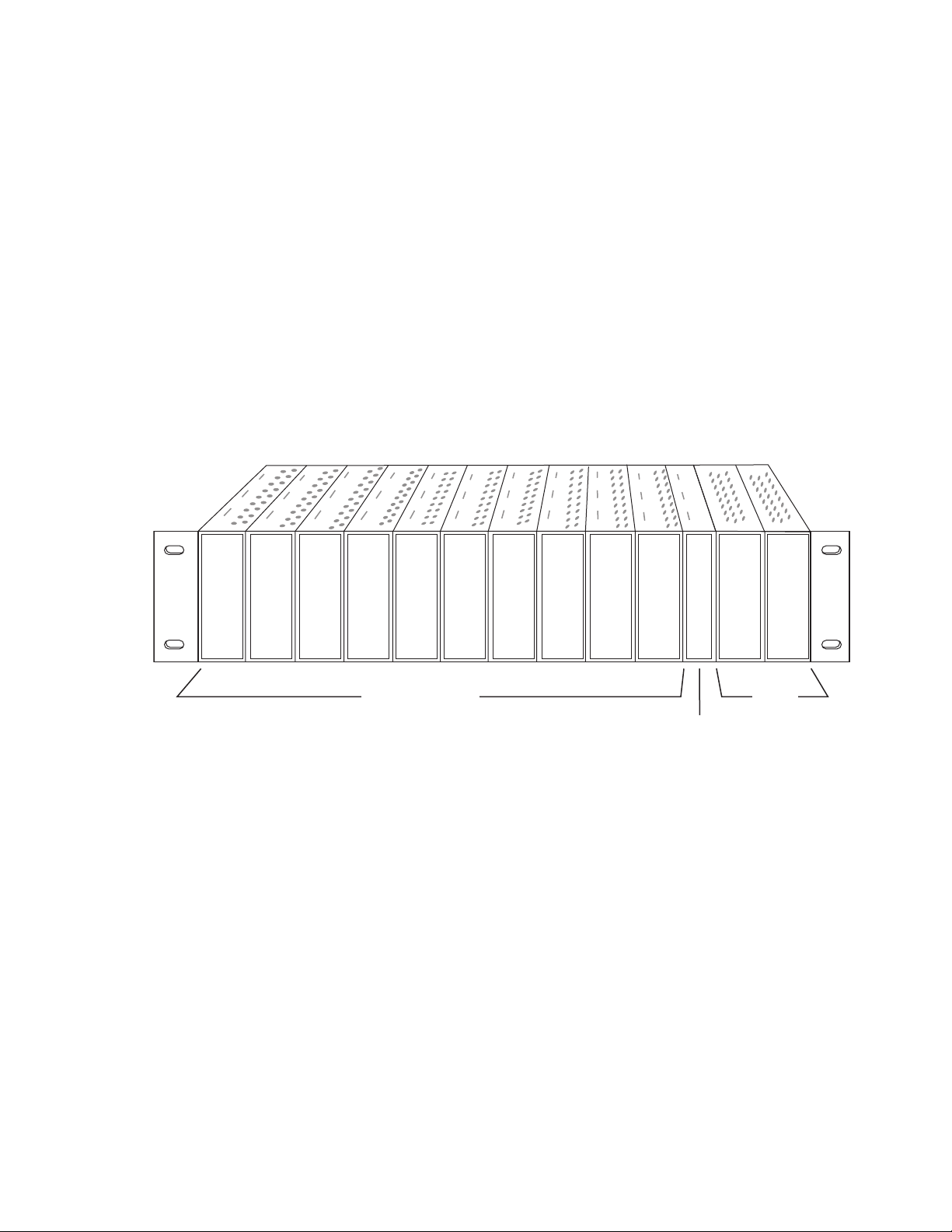
Module Placement in the Gecko 8900 Frame
Frame Controller or
8900NET Network
Interface Module
Any 8900 Module
Power
Supplies
(only)
8208_04r1
There are ten cell locations in the frame to accommodate either analog or
digital modules. These are the left ten locations. Refer to
The two cells on the right are allocated for the power supplies. For additional information concerning the Power Supply module, refer to the 8900
Gecko Frames or the GeckoFlex Frames Manual.
The third cell from the right is allocated for the Frame Monitor or 8900NET
Network Interface module. These modules provide health monitoring and
control options.
Note If using an 8900NET module in the frame, it must be running software
version 4.3.0 or higher for full networking functionality and proper remote
operation of the 8964ENC module.
Figure 1. Gecko 8900 Series Frame
Installation
Figure 1.
8964ENC/-FS — Instruction Manual 11
Page 12
Installation
8208-03
J1 J2
J3 J4
J5 J6
J7 J8
J9 J10
IN
DA1
J2
J4
J6
J8
J1 J2
J3 J4
J5 J6
J7 J8
J9 J10
IN
DA3
J1 J2
J3 J4
J5 J6
J7 J8
J9 J10
IN
DA5
J1 J2
J3 J4
J5 J6
J7 J8
J9 J10
IN
DA2
J1 J2
J3 J4
J5 J6
J7 J8
J9 J10
IN
DA7
J1 J2
J3 J4
J5 J6
J7 J8
J9 J10
IN
DA9
J1 J2
J3 J4
J5 J6
J7 J8
J9 J10
IN
DA4
J2
J4
J6
J8
J1 J2
J3 J4
J5 J6
J7 J8
J9 J10
IN
DA6
J2
J4
J6
J8
J1 J2
J3 J4
J5 J6
J7 J8
J9 J10
IN
DA8
J2
J4
J6
J8
J1 J2
J3 J4
J5 J6
J7 J8
J9 J10
IN
DA10
O
U
T
O
U
T
O
U
T
O
U
T
O
U
T
O
U
T
O
U
T
O
U
T
O
U
T
O
U
T
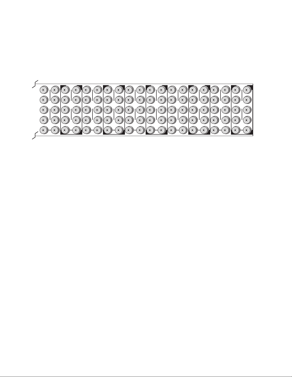
8900 module slots are interchangeable within the frame. There are 10 BNC
connectors in each slot’s I/O group. The functional assignment of each con
nector in a group is determined by the module that is placed in that slot.
The maximum number of modules a Gecko 8900 frame can accept is ten.
Figure 2 illustrates the rear connector plate for a Gecko 8900 frame.
Figure 2. Gecko 8900 Series Frame Rear Connector
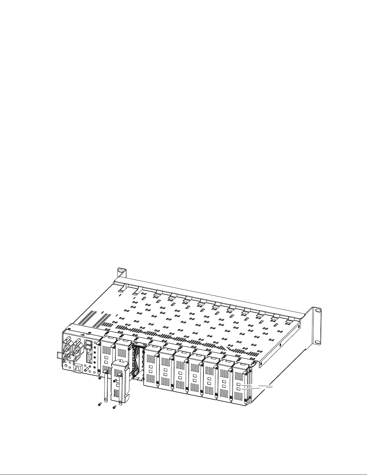
To install a module in the frame:
-
1. Insert the module, connector end first, with the component side of the
module facing to the right and the ejector tab to the top.
2. Verify that the module connector seats properly against the backplane.
3. Press in the ejector tab to seat the module.
12 8964ENC/-FS — Instruction Manual
Page 13

GeckoFlex Frame
Installation of the 8964ENC/FS module in a GeckoFlex frame includes:
1. Installing the 8900V-R rear module into the rear of the frame,
2. Placing the 8964ENC/FS module in the corresponding front frame slot,
3. Cabling and terminating signal ports.
Module Installation Precautions
Please read and follow the precautions listed below before installing the
front and rear modules:
• Use standard anti-static procedures during installation. As modules
• Install the rear module first, then install the front module.
Installation
and
can be installed or removed when the GeckoFlex frame is powered up,
before removing the cover, please use an anti-static bracelet or heel
strap tied to a metal part of the frame.
• When installing or removing a rear module, loosen or tighten the
screws holding the retainer clips to the frame manually with the
retainer clip tool provided inside the front cover of the frame or use a
2 mm (5/64”) hex screwdriver. Please do not use an electric screwdriver.
Note On newer 751- version GeckoFlex frames, a Rear Retainer Clip removal tool
and 2 extra retainer clips and screws for installing them are provided on the
inside of the frame cover.
• Make every effort to leave the screws holding the retainer clips in place
(do not remove them completely). They are very small and can easily
drop into other equipment causing a shorting hazard. (Two turns of the
screw should be enough to loosen the screws, 3 turns or more will
remove it.)
• When installing a rear module, tighten the screws on the retainer clips
just until snug. Do not apply more force than is necessary to seat the
rear module. Do not use an electric screwdriver. Refer to the rear
retainer screw torque specification in the Mechanical section of Tabl e 7 on
page 62.
8964ENC/-FS — Instruction Manual 13
Page 14
Installation
Rear Module Installation
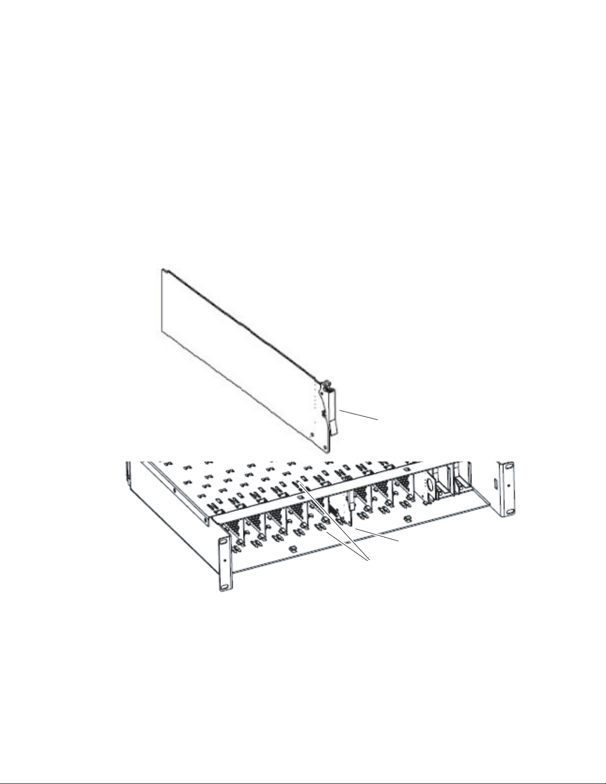
All unused rear slots in a GeckoFlex frame should have a blank rear
adapter cover installed.
1. Each 8900V-R rear module or blank rear adapter cover is held in place
by two retainer clips as shown in Figure 3. Loosen (but do not remove
completely) the two screws holding each retainer clip to the frame with
a 2 mm (5/64”) hex screwdriver or the Rear Retainer Clip tool provided
(751- frames only). Pull up on the retainer to remove it, leaving the
screws in place.
CAUTION Be careful to leave the screws in place as they can be easily lost or fall into
equipment below the frame creating a shorting hazard.
2. Remove the blank rear adapter cover by inserting needlenose pliers
into the slots in the top and bottom of the blank and pulling it off.
Note To remove a rear module already installed, follow the same steps. It is helpful
to first remove the front module so the rear can be pulled out more easily.
3. Insert the rear module into the empty slot.
4. Replace each retainer clip over the two screws on both sides of the
module and push down to seat the retainer.
5. Tighten the screws for each retainer clip just until they are snug. Do not
force or torque the screws too tightly.
Figure 3. Installing Rear Module
8444_23r0
Use retainer clip or
needlenose pliers
to pull out blank after
removing retainer clips
14 8964ENC/-FS — Instruction Manual
Page 15
Front Module Installation
Slide top and bottom card carriers on module
over top and bottom guides on right of slot.
Module installed
Locking Pin
Front Module Side View
0642_10r0
After installing the rear module, install the front module as follows:
1. Remove the front cover of the frame if required.
2. Locate the corresponding front slot.
3. Insert the front module so that the plastic card guides on the module
top and bottom edges go over the upper and lower raised rail guides on
the right of the top and bottom of the slot (Figure 4).
4. Carefully slide the module into the rear connector.
5. Lock the front module ejector tab into the locking pin.
Figure 4. Front Module Installation
Installation
8964ENC/-FS — Instruction Manual 15
Page 16
Installation
J1 J2
J3 J4
J5 J6
J7 J8
J9 J10
Reference In
Loop-Through
8209_11r0
8900V-R
SDI
Input 1
SDI
Input 2
SDI
Input 3
SDI
Input 3
NTSC/PAL
Output 1
NTSC/PAL
Output 2
NTSC/PAL
Output 2
NTSC/PAL
Output 2
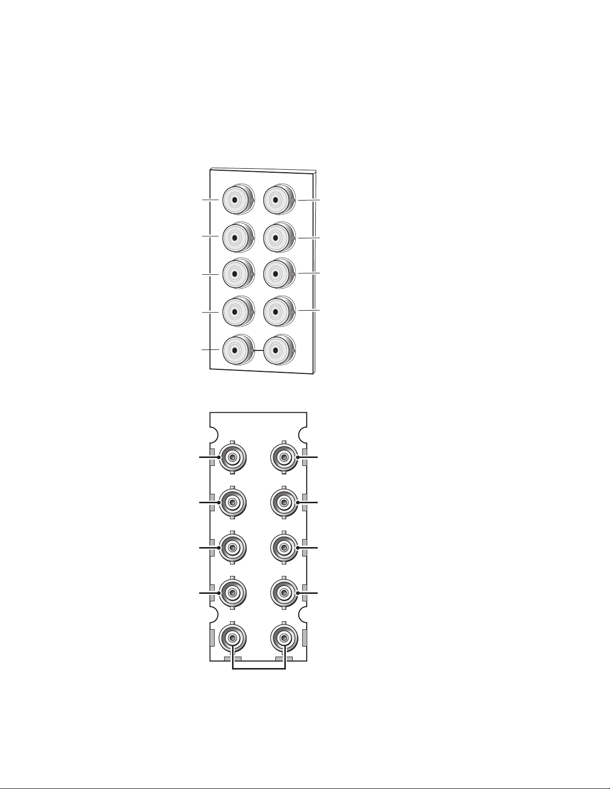
Cabling
Cabling to and from the module is done at the back of the Gecko frame
Figure 5) and the 8900V-R rear module on a GeckoFlex frame (Figure 6) as
(
described below for both frame types.
Figure 5. Input/Output Connectors – Gecko Frame
X
SDI In 1
SDI In 2
SDI In 3
SDI In 4
Reference In
(loop-through)
Figure 6. Input/Output Connectors – 8900V-R GeckoFlex Frame
CV Out 1
J1
J2
J2
CV Out 2
J3
J4
J4
CV Out 3
J5
J6
J6
CV Out 4
J7
J9 J10
IN
J8
J8
8209_02
16 8964ENC/-FS — Instruction Manual
Page 17

Inputs
Four serial digital video inputs are provided at BNCs J1, J3, J5, and J7. The
inputs are non-looping and internally terminated.
Outputs
Four corresponding NTSC or PAL composite video outputs are provided at
BNCs J2, J4, J6, and J8.
Reference Loop-through Input
Connect an NTSC/PAL analog color black reference source (with Signal to
Noise specification of > 40 dB recommended) to one of the loop-through
reference connectors, J9 or J10. Terminate the unused connector into 75 ¾ if
the signal is not looped to other equipment.
Note The line rate for the module (all four encoder channels) will be auto-detected
from the Reference In signal. The line rate must match the reference input.
Installation
8964ENC/-FS — Instruction Manual 17
Page 18
Power Up
Power Up
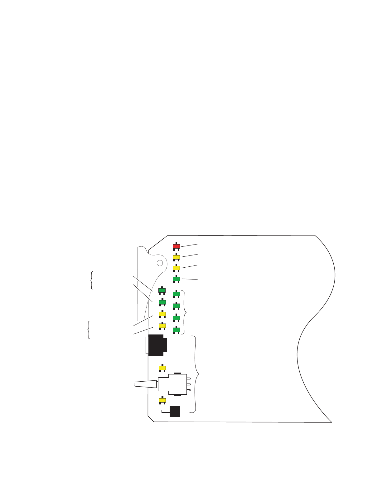
Operation Indicator LEDs
The front LED indicators and configuration switches are illustrated in
Figure 7. Upon power-up, the green PWR LED should light and the yellow
CONF LED should illuminate for a few seconds for the duration of module
initialization.
Note When a module is first plugged into a GeckoFlex frame, the 8900NET module
(if present) may report a momentary fault. This will clear once the module has
booted up.
With factory default configuration and a valid input signal connected, the
green PWR LED and one of the green signal standard LEDs (525 or 625)
should illuminate (refer to
Ta bl e 2 on page 19 to see the possible operating
indicator combinations).
Video input presence on each encoder channel is indicated by the CH1–
CH4 green LEDs on.
Figure 7. LEDs and Configuration Switches
One LED will be
on to indicate
525 or 625 line
reference is present
525 – Green LED
625 – Green LED
Module Configuration
Active Channel
Control Indictors
CM1 – Yellow LED
CM0 – Yellow LED
525 625 CM1 CM0
FUNCTION
2ND
UP
DOWN
CSM
MODE
CNTRL
FAULT
COMM CONF PWR
CH1 CH2 CH3 CH4
2ND LED
FAULT – Red LED is off during normal operation.
COMM – Yellow LED on indicates frame bus traffic.
CONF – Yellow LED on indicates module is initiating,
changing operating mode, or programming hardware.
PWR – Green LED on indicates power OK.
CH 1 – CH4 Green LEDs on indicates
signal present on CH1, 2, 3 and 4.
Module Configuration Switches and LEDs.
8209_05
18 8964ENC/-FS — Instruction Manual
Page 19

Table 2. Board Edge LED Names and Meaning
LED Indication Condition
FAULT
(red)
COMM
(yellow)
CONF
(yellow)
PWR
(green)
625
(green)
525
(green)
CM1
(yellow)
CM0
(yellow)
CH1
(green)
CH2
(green)
CH3
(green)
CH4
(green)
2ND
(yellow)
CSM
(yellow)
Off Normal operation.
On continuously Module has detected an internal fault. (Refer to Status Monitoring on page 64.)
Flashing Configuration problems. Check inputs and settings. Missing video.
Off No activity on frame communication bus.
3 Quick Pulses Locate Module command received by the module from a remote control system.
Short flash Activity present on the frame communication bus.
Off Module is in normal operating mode.
On continuously Module is initializing, changing operating modes or programming hardware.
3 Quick Pulses Locate Module command received by the module from a remote control system.
Off No power to module or module’s DC/DC converter failed.
On continuously Normal operation, module is powered.
Off No reference or standard is other than 625.
On continuously Valid 625 video reference is present.
Off No reference or standard is other than 525.
On continuously Valid 525 video reference is present.
Off
On
Off
On
Off No signal present on Channel 1.
On continuously Valid signal is present on Channel 1.
Flashing Input signal line rate does not match reference.
Off No signal present on Channel 2.
On continuously Valid signal is present on Channel 2.
Flashing Input signal line rate does not match reference.
Off No signal present on Channel 3.
On continuously Valid signal is present on Channel 3.
Flashing Input signal line rate does not match reference.
Off No signal present on Channel 4.
On continuously Valid signal is present on Channel 4.
Flashing Input signal line rate does not match reference.
Off Rotary switch is addressing Bank 1 configuration functions.
On continuously Rotary switch is addressing Bank 2 configuration functions.
Flashing Rotary switch is addressing Bank 3 configuration functions.
Off Paddle switch controls current Bank parameter mode.
On continuously Paddle switch controls channel selection.
On/Off combination Indicates what channel is enabled for configuration when Channel
Select Mode (CSM) LED is on (described in Table 5 on page 28).
Power Up
8964ENC/-FS — Instruction Manual 19
Page 20

Configuration
Configuration
Configuration Summary
The 8964ENC can be configured locally using onboard switches or
remotely using the 8900NET network interface GUI or a networked control
panel.
Refer to the following sections for configuration instructions:
• Configuration Summary (page 20)
• Local Onboard Module Configuration (page 27)
• Remote Control and Monitoring (page 33)
Operation of these control types is explained in detail in their respective
sections of this manual.
format of all parameters and their ranges, default values, and remote, local,
and control panel function names and locations for setting each value.
Ta bl e 8 on page 67 provides a summary in table
This section provides a summary of all parameters that can be configured
on the 8964ENC module. The video processing configuration is described
by what line types will be affected by the adjustments or choices made. Use
this section in conjunction with the specific configuration method instruc
tions for each configuration type.
Video Timing and Freeze Controls
With a standard 8964ENC module with no Frame Sync the following line
sync timing adjustments are available:
• Horizontal Timing – adjusts the horizontal delay of the channel output
in half pixels. and
• Fine Phase Adjustment – adjusts the horizontal fine phase relative to
the input sync reference (in percent of 37 ns).
With an 8964ENC-FS module (8964ENC with Frame Sync, see Module
Option Upgrade on page 61), the following vertical timing adjustments can
be made:
• Horizontal Timing – identical to the line sync timing above.
• Fine Phase Adjustment – identical to the fine phase timing above.
-
• Vertical Timing – adjusts vertical delay in line increments.
20 8964ENC/-FS — Instruction Manual
Page 21

Also available with the 8964ENC-FS are the following freeze controls (one
must be selected from the five choices):
• AutoBlue – when AutoBlue is enabled on a channel, the output will
automatically freeze to a blue screen when the input signal is lost on
that channel.
• AutoFreeze – when AutoFreeze is enabled on a channel, the output will
automatically freeze on the last valid field when the input signal is lost
on that channel.
• Field 1 – manually freeze the output signal on field 1 of the last frame.
• Field 2 – manually freeze the output signal on field 2 of the last frame.
• Frame – manually freeze the output signal on the last frame.
Note A field freeze provides less resolution and no motion artifacts in the output.
In frame mode, the resolution is higher since both fields are present, but the
presentation of the two fields can cause motion artifacts.
Picture Enhancer Controls
Configuration
The Picture Enhancer feature is standard on the 8964ENC and 8964ENC-FS
modules. This feature allows separate picture enhancement control on each
channel output.
Use the following controls for bypassing or disabling picture enhancement:
• Bypass – the Picture Enhancer circuitry can be bypassed to decrease the
amount of delay in the module if required.
• Disable – the Picture Enhancer process can be disabled, still routing the
signal through the Picture Enhancement circuitry.
When Picture enhancement is enabled, the following controls are available:
• Split screen – split the output screen to view the original video on the
left and the enhanced video on the right.
• Detail level – set the amount of picture enhancement detail based on the
split screen comparison.
• Overshoot protection – set the amount of clipping looking at a wave-
form monitor.
8964ENC/-FS — Instruction Manual 21
Page 22

Configuration
Vertical Blanking Interval Controls
The 8964ENC provides line-by-line vertical blanking interval (VBI) processing.
Line Categories
The line categories used in the configuration of the video signal for the
8964ENC are defined as follows:
• F_Active Lines – the portion of the active video that is fixed and always
treated by the module as carrying active video (not programmable).
• P_Active Lines – lines in the active video that can be configured by the
user to carry either active video or be reserved for carrying user data.
• CVBI – the lines in the vertical interval that can be configured by the
user.
• FVBI – the line in the vertical blanking interval that are fixed and are not
configurable.
The line numbers for each category above are defined in Tab le 3 for both
525 and 625 line rates.
Table 3. Line Numbers for 8964ENC Line Categories
Line Categories
Label
F_Active
P_Active
CVBI
FVBI
Start End Start End
25 (F1)
288 (F2)
21 (F1)
284 (F2)
10 (F1)
273 (F2)
1 (F1)
264 (F2)
525 625
263 (F1)
525 (F2)
24 (F1)
287 (F2)
20 (F1)
283 (F2)
9 (F1)
272 (F2)
29 (F1)
342 (F2)
24 (F1)
337 (F2)
6 (F1)
319 (F2)
624 (F1)
311 (F2)
310 (F1)
623 (F2)
28 (F1)
341 (F2)
23 (F1)
336 (F2)
5 (F1)
318 (F2)
22 8964ENC/-FS — Instruction Manual
Page 23

Configuration
Line pairs in the P_Active line category can be reserved for carrying data
by configuring Data Line Pairs with local or remote controls. Refer to
Ta bl e 4 for a listing of the Data Line Pairs lines that are available with each
setting.
Table 4. Lines Reserved for Carrying Data
525 Line
Selection
None None None None
21/284 21/284 24/337 24/337
22/285 21/284 – 22/285 25/338 24/337 – 25/338
23/286 21/284 – 23/286 26/339 24/337 – 26/339
24/287 21/284 – 24/287 27/340 24/337 – 27/340
Data Line Pairs
Reserved
625 Line
Selection
28/341 24/337 – 28/341
Data Line Pairs
Reserved
Programmable VBI and Active Picture Lines
The programmable lines in the vertical blanking interval include the configurable VBI lines (CVBI). Configurable active picture lines (P_Active) can
be reserved for carrying data (refer to
These line pairs can be configured for the following:
• Blank – in local mode, select On to blank all lines of CVBI or Off to not
blank. In remote mode, lines can be blanked or passed on a line-by-line
basis with the web page (toothed blanking).
• VBI Setup – in 525 mode, a control is provided for turning VBI setup on
or off. This is a global control that affects all lines of VBI.
Tab le 4).
Note For this control to be active, the Active Video Setup control on the composite
output must be set to on.
8964ENC/-FS — Instruction Manual 23
Page 24

Configuration
Video Processing Adjustments
The controls for video processing on each channel are the following:
• Test signal generator – when on, enables the internal test signal generator to output a 75% Color Bars test signal to the channel output.
Note When the internally generated color bars test signal output is enabled, the rel-
ative sync and burst may be offset in relation to the input SDI stream timing.
• Chroma Kill – removes all chroma from the signal (black and white).
This is a global control, affecting chroma on all lines of active video and
includes the VBI.
• Burst On/Off – the burst can be turned on (default) or off with a control
in the Video Processor section.
• Black Clip – set the level of black clipping with the remote controls (no
local control).
• Contrast/Y Gain – adjusts the percentage of luminance relative to
white.
• Saturation/Chroma Gain – adjusts percentage of saturation and
chroma gain relative to 100% saturation.
• Brightness/Y Offset – adjusts amount of brightness/Y offset in mV.
• Hue/Chroma Phase – adjusts hue/chroma phase in degrees for both
line rates (525 and 625).
Note Test signals are not adjustable in the Video Processing controls.
24 8964ENC/-FS — Instruction Manual
Page 25

Noise Reducer Controls
The Noise Reducer feature is standard on the 8964ENC and 8964ENC-FS
modules. This feature allows separate noise reduction control on each
channel output. The use of these controls depends on the amount and type
of noise present on the signal.
The Noise Reducer process can be enabled or disabled.
When noise reduction is enabled, the following controls are available:
• Filter Select– the type of noise filter may be selected on the web page
only. Choice of the noise filter depends on the type of noise present.
• Level – adjust the noise level (amount of noise reduction).
• Threshold – adjust the noise threshold until the noise is reduced but
video distortion is minimal.
Composite Output Adjustments
The composite output on each channel can be adjusted for the following:
Configuration
• Add Active Video Setup – add setup to active video.
Note This control also enables or disables the VBI Setup control.
• Output Video Gain – adjust the percent of output video gain relative to
1 V p-p.
Timing and Genlock Considerations
This section is provided for information on some important points about
module reference input sync and color frame timing considerations.
Reference Input Sync
The module is locked to the reference input sync. The following reference
input sync considerations should be noted:
• Jitter performance of the module is influenced by the time base jitter of
the reference input sync.
• Reference input sync timing determines the color burst/output timing.
If a sync changeover is used for the sync reference, the timing of both
sync sources must match. This ensures that the output burst phase of
the module does not change and the timing from the 8964ENC remains
consistent if the reference input sync switches.
8964ENC/-FS — Instruction Manual 25
Page 26

Configuration
12341234
12341234
12121212
12341234
12121212
12341234
12341234
12121212
12341234
8209_10
Reference Input
Reference Input
Reference Input
SDI Input
Encoder Output
SDI Input
Encoder Output
SDI Input
Encoder Output
4-Field Sequence
4-Field Sequence
4-Field Sequence
2-Field Sequence
4-Field Sequence
Color Frame
When converting from a SDI input signal to NTSC or PAL output, a color
frame is chosen by the 8964ENC module based on the position of the closest
SDI Field 1 to Field 1 of the reference input. NTSC video has a 4-field color
frame sequence, while PAL has an 8-field sequence. SDI video coming into
the module has a 2-field sequence.
As illustrated in the three examples in Figure 8 for a 525 reference input, the
relationship of the SDI input Field 1 to the reference input Field 1 will determine the color frame of the encoder video output.
Note When the SDI video is delayed one field, the color frame jumps back two
fields to the closest Field 1.
Figure 8. Color Frame Output (NTSC)
26 8964ENC/-FS — Instruction Manual
Page 27

Local Onboard Module Configuration
The 8964ENC module can be configured locally using the rotary and
paddle switches. Several LEDs interact with the switches to indicate status
of the configuration process.
Configuration Switches and Controls
Each of the four encoder channels is adjusted separately. Selection of each
channel is done with the paddle switch while in Channel Select Mode as
explained below. Refer to
tions. Use the onboard configuration components as follows:
• SW1 Function (rotary) switch — This switch accesses a desired function
for configuration (see Tabl e 6 o n pa ge 31). The switch addresses three
banks of functions; each bank has 16 possible positions (0 through 9 and
A through F). Not all positions are used.
The next bank of functions is accessed each time the Function switch
makes a complete revolution past zero (or back through F): While in
Bank 1, a complete revolution past zero accesses Bank 2; while in Bank
2, a complete revolution past zero accesses Bank 3. The yellow 2ND
LED indicates which bank is currently being accessed.
Figure 9 on page 28 for the following descrip-
Configuration
Note The Function switch should be kept in position 0 in any bank (parked) when
not in use to avoid any inadvertent change in configuration. Position 0 in each
bank is inactive.
• 2ND (second Function) yellow LED – when off, indicates that the rotary
switch is addressing the first bank of functions. When on, indicates that
the rotary switch is addressing the second bank of functions. When
flashing, indicates that rotary switch is addressing the third bank of
functions.
• SW3 (paddle) switch – actuates or selects the desired setting or channel
selection for the selected function when the switch is held momentarily
in either the up or down position. Switch between Parameter and
Channel Select Mode with pushbutton SW2.
• CSM (Channel Select Mode) yellow LED – when on, paddle switch is in
Channel Select Mode. Use the paddle switch to select channel 1, 2, 3, or
4. When off, paddle switch is in Parameter mode.
• CM1 and CM0 yellow LEDs – indicate what channel is active for adjust-
ment. Refer to Table 5 on page 28.
• SW2 (pushbutton) switch – press to toggle assignment of paddle switch
SW3 between Parameter mode (CSM LED off) and Channel Select
Mode (CSM LED on).
• CONF (configuring) yellow LED – when on, indicates the module is
programming hardware.
8964ENC/-FS — Instruction Manual 27
Page 28

Configuration
Figure 9. Onboard Configuration Components – Front View
Ejector Tab
CONF – Yellow LED on indicates module is initiating,
changing operating mode, or updating firmware
CM1 – Yellow LED
Indicate active channel control (see table in text)
CM0 – Yellow LED
5
6
4
7
3
8
2
1
0
F
E
SW1 – 16-position Function rotary switch – accesses 3 banks of
9
A
B
controls. Bank selected is indicted by state of 2ND LED.
C
D
2ND LED – Bank 1 = Off , Bank 2 = On, Bank 3 = flashing
SW3 – Paddle switch for incrementing parameter values (Parameter mode)
or selecting active channel (CSM, Channel Select Mode)
CSM LED – on in Channel Select Mode (use paddle to select channel)
8209_07r1
SW2 – Pushbutton switch to toggle between Parameter
and CSM modes
Refer to Tab le 5 for reading the CM1 and CM0 active channel LED indica-
tors.
Table 5. CM1 and CM0 LED Table
CM1 LED State
Off Off Channel 1 is active
Off On Channel 2 is active
On Off Channel 3 is active
On On Channel 4 is active
CM0 LED
State
Channel Control
28 8964ENC/-FS — Instruction Manual
Page 29

Onboard Jumpers
8209_06r1
Place jumper in Local position
to lock out remote access.
Function rotary switch
2ND Function LED
CM1 LED
CM0 LED
Pushbutton switch
Paddle switch
LOC&REM (2–3)
CSM LED
Remote Lockout
LOCAL (1–2)
JP1
On Screen Display Control
JP3
OSD EN (2-3)
Two onboard jumpers must be set for the following:
• Jumper JP1 allows (LOC&REM position) or locks out (LOCAL posi-
tion) remote control.
• Jumper JP3, OSD enables (OSD_EN pins 2-3) or disables (pins 1-2)
control of the OSD (On Screen Display).
The On Screen Display (OSD) graphic can be enabled on the output of
each channel to allow viewing of the currently selected Rotary switch
function and the currently assigned parameters. The OSD is provided
for an aid in configuring the module in local mode and should be
turned off on each channel with either the local or remote controls
before broadcasting the signal. You may also set this jumper to disable
the OSD completely after the module is configured to prevent the OSD
information from being put on-air.
When control is enabled with jumper JP3, the OSD for each channel can
be turned on or off with either local or remote controls.
Configuration
Figure 10. Module Configuration Switches and LEDs
8964ENC/-FS — Instruction Manual 29
Page 30

Configuration
8964ENC Module Onboard Configuration Settings
Onboard configuration is done on a channel-by-channel basis, there is no
gang mode (apply settings to all channels). You may use an on-screen
display on the output of each channel to view the parameters being
adjusted.
Control of the OSD function must first be enabled locally by setting jumper
JP3 (
Figure 10) to either disabled, pins 1-2, or enabled, OSD_EN (pins 2-3).
Once OSD control has been enabled with JP3, it can be turned on or off with
individual local channel controls (Bank 1/Position 1) or through the web
browser (refer to
To make a configuration setting:
1. Select the channel to be adjusted by pressing pushbutton SW2 to toggle
to the Channel Select Mode (yellow CSM LED on). This allows using
the paddle switch to increment through the channel selections. The
currently selected channel is indicated by the state of the CM1 and CM0
LED. Refer to Table 5 on page 28 for reading LED states.
2. When the desired channel is active, use pushbutton SW2 to toggle back
to Parameter mode (CSM LED off).
OSD Control Web Page on page 57).
3. Rotate the Function switch to Bank 1 (2ND LED off) or Bank 2
(2ND LED on) or Bank 3 (2ND LED slow flash) and to the desired
function within that bank.
4. Move the paddle switch to the up or down position and hold
momentarily to set the desired function (refer to Table 6 on page 31).
Note Holding the paddle switch in the up or down position for more than a half
second will automatically accelerate through the value range for parameters
with 256 or more values. The full range can be accessed in about 10 seconds.
30 8964ENC/-FS — Instruction Manual
Page 31

Function
Switch
Setting
Bank 1 (2ND LED off)
0 – – Default position for normal operation (parked)
1 On Off Turn OSD (on screen display) on or off
2 Yes No Add setup to active video 1:2 Add Setup (525 only)
3 – – Not used
4 Increase Decrease Adjust output video gain (% relative to 1 V p-p) 1:4 Output video gain
5 Increase Decrease Adjust contrast/Y gain 1:5 Contrast/Y Gain
6 Increase Decrease Adjust brightness/Y offset 1:6 Brightness/Y Offset
7 Increase Decrease Adjust saturation/chroma gain 1:7 Sat/Chroma Gain
8 Increase Decrease Adjust hue/chroma phase 1:8 Hue/Chroma Phase
Bank 1 (2ND LED off)
9 – – Not used
A On Off Turn Burst on or off 1:A Burst
B On Off Turn Chroma Kill on and off 1:B Chroma Kill
C On Off Turn output test signal generator on or off 1:C Test Signal
D – – Not used
E >2s Learn Recall
F – Recall Recall factory defaults 1:F Factory default
Bank 2 (2ND LED on)
0 – – Default position for normal operation (parked). 2:0 (parked position information)
1 None 21/284 or 24/337
2 22/285 or 25/338 23/286 or 26/339 2:2 Rsv for data
3 24/287 or 27/340 28/341 (625 only) 2:3 Rsv for data
4 On Off Turn VBI blanking on or off (all VBI lines). 2:4 VBI Blank
5 On Off Turn VBI setup on for off (all VBI lines) 2:5 Add VBI Setup (525 only)
6 – 9 – – Not used
A Increase Decrease Adjust fine phase of output signal 2:A Fine Phase Timing
B Increase Decrease Adjust horizontal timing 2:B Horizontal Timing
Bank 2 (2ND LED on)
C Increase Decrease Adjust vertical timing 2:C Vertical Timing
D AutoBlue Field 1 Select Freeze mode 2:D Frz Mode
E Field 2 Frame Select Freeze mode 2:E Frz Mode
F AutoFrz AutoBlue Select Freeze mode: AutoFreeze 2:F Frz Mode: AutoFrz
Paddle
Switch Up
Table 6. Local Rotary and Paddle Switch Functions
Paddle
Switch Down
Hold paddle for more than 2 seconds to learn current channel settings into E-MEM register. Select
down to Recall.
Select P_Active lines to reserve for data
(525 or 625). See Table 4 on page 23.
These controls (2C – 2F) active for the 8964ENC -FS only
Function Description OSD Text Summary
Configuration
Ch#, Channel Name 1:0 (bank/#)
Model #
HW ver x.x SW ver x.x
FW: xx SN: xxxxxxxxxx
Ch#, Channel Name 1:1
Video: rate or NO Ref: rate or NO
On screen disp: (current state)
Choices or scroll bar
1:E EMEM
2:1 Rsv for data
8964ENC/-FS — Instruction Manual 31
Page 32

Configuration
Function
Switch
Setting
Bank 3 (2ND LED flashing)
0 – – Default position for normal operation (parked). 3:0 (parked position information)
1 – 7 Not used
8 Enable Disable Enable or disable noise reducer process 3:8 NR Process:
9 Increase Decrease Adjust noise reducer level 3:9 NR Level:
A Increase Decrease Adjust noise threshold level 3:A NR Threshold:
B Disable Bypass Bypass Picture Enhancer circuitry 3:B PE Process:
C Enable Disable Enable or disable Picture Enhancer process 3:C PE Process:
D On Off Turn split screen on or off 3:D PE Split Scrn:
Bank 3 (2ND LED flashing)
E Increase Decrease Adjust Picture Enhancer detail level 3:E PE Detail Level:
F Increase Decrease Adjust Picture Enhancer overshoot protection 3:F PE Overshoot Protect:
Table 6. Local Rotary and Paddle Switch Functions
Paddle
Switch Up
Paddle
Switch Down
Function Description OSD Text Summary
32 8964ENC/-FS — Instruction Manual
Page 33

Remote Configuration
The 8964ENC and 8964ENC-FS configuration and monitoring can also be
performed remotely using a web browser interface or a networked Newton
Control Panel with an 8900NET Network Interface module present in the
GeckoFlex frame (8900FFN). Each of these interfaces is described below. A
summary table of all module parameters including defaults, ranges, and
Newton Control Panel controls is given in
8900NET Module Information
Refer to the 8900NET Network Interface Module Instruction Manual (software
version 4.3.0) for information on the 8900NET Network Interface Module
and setting up and operating the GeckoFlex 8900 frame network.
Note Upgrade software and instructions for the 8900NET can be downloaded from
the Grass Valley web site. Refer to Contacting Grass Valley on page 4.
Newton Control Panel Configuration
Configuration
Tab le 8 on page 67.
A Newton Control Panel (hard or soft version) can be interfaced to the
GeckoFlex frame over the local network. Refer to the documentation that
accompanies the Newton Modular Control System for installation, config
uration, and operation information.
Control panel access offers the following considerations for module configuration and monitoring:
• Ability to separate system level tasks from operation ones, minimizing
the potential for on-air mistakes.
• Ability to group modular products—regardless of their physical locations—into logical groups (channels) that you can easily manipulate
with user-configured knobs.
• Recommended for real-time control of module configuration parameters, providing the fastest response time.
Note Not all module functions are available with the control panel, such as factory
default recalls.
-
8964ENC/-FS — Instruction Manual 33
Page 34

Configuration
An example of the Newton Configurator is shown in Figure 11.
Figure 11. Newton Configurator Example
Web Browser Interface
The web browser interface provides a graphical representation of module
configuration and monitoring.
Use of the web interface offers the following considerations (some functions depend on individual module functionality):
• Provides complete access to all module status and configuration functions, including naming of inputs and outputs, factory parameter and
name default recalls, Save/Load module configuration functions, slot
configurations, and SNMP monitoring controls.
• Web access will require some normal network time delays for processing of information.
• Configuration parameter changes may require pressing
Enter, upload processing time. A manual screen refresh is recommended
after changing parameters.
• Web interface recommended for setting up module signal and slot
names, and reporting status for SNMP and monitoring.
Refer to the Status web page shown in Figure 12 on page 35. The 8900
modules can be addressed by clicking either on a specific module icon in
the frame status display or on a module name or slot number in the link list
on the left.
Apply button or
34 8964ENC/-FS — Instruction Manual
Page 35

Configuration
8208_09r3
The Links section lists the frame and its current modules. The selected link's Status
page is first displayed and the sub-list of links for the selection is opened. The sub-list
allows you to select a particular information page for the selected device.
Content display section dis
plays the information page
for the selected frame or module (frame slot icons are also
active links).
Refresh button for manual
update of page
Note The physical appearance of the graphics on the web pages shown in this
manual represent the use of a particular platform, browser and version of
8900NET module software. They are provided for reference only. Web pages
will differ depending on the type of platform and browser you are using and
the version of the 8900NET software installed in your system. This manual
reflects an 8900NET module with software version 4.3.0, using Internet
Explorer, the recommended web browser, and Windows XP operating
system.
For information on module status, fault monitoring and reporting shown
on the Status web page, refer to
Figure 12. Gecko 8900 Frame Status Web Page
Status Web Page on page 38.
8964ENC/-FS — Instruction Manual 35
Page 36

Configuration
Pulldown Menus
Button
Radio button
Check box
Refresh button
Coarse Adjust
Fine Adjust
Enter
Low Limit
Status Indicator
Entry Field
High Limit
Web Page Operations and Functional Elements
The following conventions and functional elements (shown at left) are used
in web page operations. (The examples shown throughout this manual rep
resent 8900NET software version 4.3.0):
• Pulldown menus allow you to choose selections from a list.
• Clicking on a button performs an immediate action such as recall of
defaults, clearing of states, learning configurations, and selecting all or
none of a selection.
• Radio buttons are used to make a choice of one parameter in a group.
• Check boxes are used when a selection can be enabled or included in a
group. Multiple check box selections or enables can be made for some
parameters.
Refresh button (circular arrow) is provided at the top of each web page
•A
for manual refresh to view recently changed parameters.
• Each numerical adjustment control has a
right top double arrows) which increases or decreases the step value by
a factor of 10. The
Fine adjust button (left and right inside single arrows)
increases or decreases the step value by 1.
To change a value, use the arrow button controls or enter a value into
the number field and select the
Enter button (*) or use the Enter key on
your keyboard. The Status Indicator bar will follow the value selected.
Coarse adjust button (left and
-
Status LED
Use the Low and High Limit buttons to go directly to the lowest and
highest limits for the parameter.
8341_13
After a parameter has been changed, it will take approximately 10
seconds for the change to be entered into the module backup memory.
Allow the module enough time to update the change before removing
the module from its slot.
• An entry field allows naming of various module functions such as
input or output signals, asset tag, and slot identification.
•The
Status LED icon indicates module status and is a link to the module
Status web page where status is reported.
LED colors indicate:
• Green = Pass – no problems detected
• Yellow = Configuration error warning
• Red = Fault condition detected (presence of at least one alarm)
36 8964ENC/-FS — Instruction Manual
Page 37

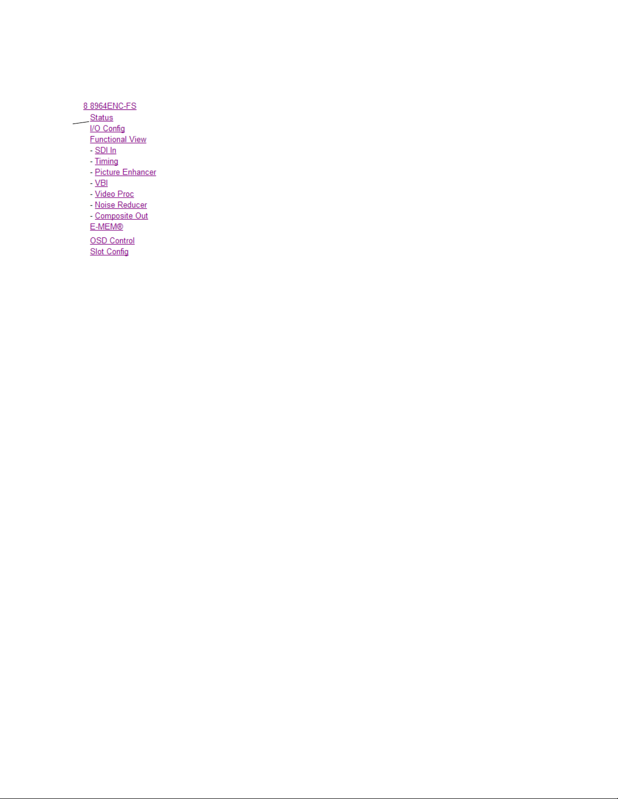
8964ENC Links and Web Pages
The 8900 GUI provides the following links and web pages for the 8964ENC
module (
• Status – reports input and reference signal status and module informa-
• I/O Config – shows a graphic representation of inputs and outputs to
• Functional View – shows a block diagram of the module with links to
• Module Configuration web pages for setting up the module (page 42),
• E-MEM – provides Learn and Recall functions for up to 5 E-MEM reg-
• OSD Control – provides controls to enable or disable the OSD for each
• Slot Config – provides a Locate Module function, Slot Identification,
Figure 13):
tion (page 38),
the module and allows naming of each input (page 40),
each configuration web pages (page 41),
isters along with
channel (page 57), and
and Slot Memory in addition to links to the Frame Reporting, LED
Reporting and SNMP Reporting web pages (page 58).
Save to and Load from file operations (page 53),
Configuration
Figure 13. 8964ENC/-FS Web Page Links
8964ENC/-FS — Instruction Manual 37
Page 38
Configuration
Use
this
link
Status Web Page
The Status web page (Figure 14 on page 39) shows the input signal status
of each of the encoder chan
display indicated the signal status. Refer to 8964ENC Fuse and Voltage
Testpoint Locations on
Status of the OSD displays on each output is also shown. A link to the OSD
ol web page is provided so the OSD can be enabled or disabled from
Contr
the browser. For more information on enabling or disabling an OSD display
through the web browser, refer to OSD Control Web Page on
nels and the reference input. Color coding of the
page 66 for an explanation of the color coding.
page 57.
Information about the module, such as part
ware revision and software and firmware versions are given in a read-only
ction at the bottom of the display. Enabled options are also reported.
se
An Asset Tag identifier can be assigned to the module on the Slot Config
web page
Clicking on the model number in the center box will take you to the Functional View web page illustrating a block diagram overview of the module
with links
(see Slot Config Web Page on
to each of the configuration web pages.
number, serial number, hard-
page 58).
38 8964ENC/-FS — Instruction Manual
Page 39

Figure 14. 8964ENC-FS Status Web Page
Configuration
8964ENC/-FS — Instruction Manual 39
Page 40

Configuration
Use
this
link
I/O Config Web Page
The I/O Config web page (Figure 15) shows the rear input and output connections to the module and allows you to name each input. Type the
sired input name (up to 11 characters) into the corresponding box. The
de
status of each input is indicated by the color of the display.
Note Outputs are not monitored in this application.
SNMP trap reporting of each channel input can be enabled or disabled by
selecting or deselecting the corresponding checkbox in the
column. You may disable reporting for channels not being used if desired.
The
Reporting column is also used when an SNMP monitoring application
such as NetCentral is installed.
Refer to 8964ENC Fuse and Voltage Testpoint Locations on page 66 for an
explanation of the color coding and using
tion.
Figure 15. 8964ENC I/O Config Web Page
Reporting
an SNMP monitoring applica-
40 8964ENC/-FS — Instruction Manual
Page 41

Functional View Web Page
Use
this
link
The Functional View web page (Figure 16) illustrates a block diagram of the
8964ENC module showing module functions and signal paths that are
ive or inactive in the current configuration. It can be used as a link map
act
for configuring module functions. Each block has a link to the configuration web page for that function.
Configuration
Color coding indicates active functions
nents are inactive due to hardware and/or software constraints. Underlined module functions are links to
Use the Functional View to configure the 8964ENC module in the or
the signal flow. Refer to each of the module configuration web pages given
in the next section.
Figure 16. 8964ENC Functional View Web Page
and signal flow. Grayed compo-
the web page for that function.
der of
8964ENC/-FS — Instruction Manual 41
Page 42

Configuration
Module Configuration Pages
Module configuration is provided for the following functions with the web
page GUI interface:
•SDI In (page 43)
• Timing (page 44)
• Picture Enhancer (page 47)
•VBI (page 47)
•Video Proc (page 49)
•Noise Reducer (page 51)
• Composite Out (page 52)
Read-only information about the module is given on the top of each web
page including model name and description, frame and slot location and
last E-MEM register recalled.
When a channel is selected to configure, the input name (as defined on the
I/O Config web page) will be displayed under the selected channel or will
show the default name. Each channel will show the signal reference type
(NTSC or PAL).
After making a parameter value change, click on Apply to activate settings
in each selection. Each of the four encoder channels can be adjusted sepa
rately or settings can be applied to other or all channels. Use the Apply Setting
To
(Channel 1, 2, 3 or 4 as applicable) or All buttons to apply the same values
to the other channels selected or all channels.
To reset the current channel or all channels to factory defaults, select the
Reset defaults for
Select the Back, Functional View, or Next link to navigate to the next function or
use the links on the left of the web page.
Click on the Refresh button at the top of the display to update the entire display.
Current Channel or All Channels buttons.
-
42 8964ENC/-FS — Instruction Manual
Page 43

SDI In Web Page
Use
this
link
The SDI In web page (Figure 17) provides the following status information
on each of the SDI video inputs:
Configuration
• Input Signal State (
• Input Signal Line Rate
• Detected EDH Errors
Press the
begin a new error counting sequence or the
channel counters.
Errors are also reset when the module is removed and re-installed.
Figure 17. 8964ENC SDI In Web Page
Clear Errors button for each channel to reset the error counter and
Present or Not Present)
Clear All Errors button to clear all
8964ENC/-FS — Instruction Manual 43
Page 44

Configuration
Use
this
link
Timing Web Page
Horizontal timing adjustments are provided on all models of the 8964ENC.
When no Frame Sync option is enabled, the Timing web page will display
Sync adjustments for horizontal timing and fine phase control. When
Line
Frame Sync is enabled (8964ENC-FS), the Timing web page will include
horizontal, fine phase, and vertical timing as well as freeze controls. Tab le 8
on page 67 gives a summary of controls, defaults, and parameter ranges.
Select the channel to be adjusted from the
For the 8964ENC model with Line Sync (Figure 18), adjust the following
controls:
• Horizontal Timing – adjust the correct timing output (in pixels) for each
channel.
Fine Phase Adjustment – adjust the percentage of fine horizontal phase
•
for each channel.
Figure 18. 8964ENC Line Sync Timing Web Page
Channel 1 – 4 buttons.
44 8964ENC/-FS — Instruction Manual
Page 45

Configuration
When the Frame Sync option is enabled (8964ENC-FS), the Timing page
(
Figure 19) will also include a Vertical timing adjustment and Freeze con-
trols.
Select the channel to be adjusted from the Channel 1 – 4 buttons and adjust
the following Frame Sync timing controls:
• Horizontal Timing (in pixels)
• Fine Phase (in percent relative to input sync)
• Vertical Timing (in lines)
Select one of the following buttons from Freeze Mode:
• AutoFrz – auto freeze to last valid field will occur upon loss of signal.
AutoBlue – auto freeze to blue screen will occur upon loss of signal.
•
Field 1, Field 2, or Frame – selecting one of these buttons performs an
•
immediate manual freeze on the selected channel output.
Figure 19. 8964ENC-FS Timing With Frame Sync and Freeze Controls
8964ENC/-FS — Instruction Manual 45
Page 46

Configuration
Use
this
link
Picture Enhancer Web Page
The Picture Enhancer function (Figure 20) can be enabled to adjust picture
detail or can be bypassed or di
sabled for each channel.
Select the channel to be adjusted from the
lowing adjustments with this web page:
• Select the
(for less delay through the module).
• Select the
• Use the Detail Enhancer Level control to adjust the amount of detail
enhancement on the channel output.
• Adjust the Overshoot Protection control to minimize overshoot.
Figure 20. 8964ENC Picture Enhancer Web Page
Bypass button to bypass the Picture Enhancement circuitry
Disable button to turn off picture enhancement.
Channel 1 – 4 buttons. Set the fol-
46 8964ENC/-FS — Instruction Manual
Page 47

VBI Web Page
Use
this
link
Use the VBI web page (Figure 21 on page 48 for 525 line rate or Figure 22
on page 48 for 625 line rate) to configure the pr
vertical blanking interval of each channel. Refer to Vertical Blanking Interval
Controls on page 22 for information on VBI lines. Ta bl e 8 on page 67 gives a
summary of controls, defaults, and
Configuration
ogrammable line pairs in the
parameter ranges.
Select the channel to be adjust
for the selected channel (525 or 625) will appear in the upper left of the display.
The display will show each of the programmable VBI line pairs available
at line rate and any Data Line Pairs that have been reserved for car-
for th
rying data.
Configure the VBI Line Pairs in each channel for the following:
• Blank – select to blank the Field
button to blank data on all line pairs or the
on all line pairs.
• Data Line Pairs – check one of the Reserved for Data selections to
reserve the line pair for carrying data. Line pairs reserved for data will
be graphically displayed.
• VBI Setup – in 525 mode, turn VBI setup On or Off for all VBI lines.
Note This checkbox will only be active when the Active Video Setup Add checkbox
has been selected on the Composite Out Web Page on page 52. If setup has
not been added, this selection will appear as a read-only N/A condition.
ed from the Channel 1 – 4 buttons. The line rate
1/Field 2 line pair. Select the Blank All
Pass All button to pass data
8964ENC/-FS — Instruction Manual 47
Page 48

Configuration
Active Video Setup Add
Composite Out web page
checkbox is enabled on
Figure 21. 8964ENC VBI web Page in 525 Line Rate
Refer to Figure 22 for the web page display in 625 line rate.
Figure 22. 8964ENC VBI Web Page for 625 Line Rate
48 8964ENC/-FS — Instruction Manual
Page 49

Video Proc Web Page
Use
this
link
Use the Video Proc web page (Figure 23 on page 50) to adjust the composite
output of each channel. Select the chan
Channel 1 – 4 buttons.
Make the following video processing adjustments on this web page:
Configuration
nel to be adjusted from the
• Enable a color bars test signal to the
Color Bars radio button in the Test Signal Generator control.
Select the
•Check the
Disable button for normal operation.
Chroma Kill checkbox to shut off chroma for a black and white
channel output by selecting the
picture on the channel output.
• Set the amount of Black Clip level with one of the radio buttons. Select
None for no black clipping.
• Turn Burst off or on (default) by checking or unchecking the
Burst
checkbox.
The Video Processing section provides the following controls:
• Contrast/Y Gain – adjusts the perce
ntage of luminance relative to
white.
• Saturation/Chroma Gain – adjust the percentage of saturation and
chroma gain relative to 100% saturation.
• Brightness/Y Offset – adjusts amount of brightness/Y offset in percent.
• Hue/Chroma Phase – adjust hue/chroma phase in degrees for both
line rates.
Note The Contrast Y Gain control interacts with the Brightness/Y Offset control.
Adjusting the former will affect the latter in order to maintain optimum performance and range. This is normal operation and part of the design of these
controls.
8964ENC/-FS — Instruction Manual 49
Page 50

Configuration
Figure 23. 8964ENC Video Proc Web Page
50 8964ENC/-FS — Instruction Manual
Page 51

Noise Reducer Web Page
Use
this
link
The Noise Reducer function (Figure 24) can be enabled to adjust picture
detail or can be bypassed or di
Configuration
sabled for each channel.
Select the channel to be adjusted from the
lowing adjustments with this web page:
• Check the
• Select the type of noise filter from the
• Use the Level control to adjust the amount of noise reduction on the
channel output.
• Adjust the Threshold control for whatever signal amplitude the Noise
Reducer will work on. The higher the threshold number the more noise
is reduced but more video distortion will occur.
Figure 24. 8964ENC Noise Reducer Web Page
Enable Noise Reducer checkbox to turn on noise reduction.
Channel 1 – 4 buttons. Set the fol-
Filter Select radio buttons.
8964ENC/-FS — Instruction Manual 51
Page 52

Configuration
Use
this
link
Composite Out Web Page
Use the Composite Out web page (Figure 25) to make final adjustments to
the composite output video. Select the ch
Channel 1– 4 buttons.
Set the following adjustments with this web page:
annel to be adjusted from the
• In 525 mode, check the
add setup to the active output video.
Note The VBI setup on the VBI Web Page on page 47 follows the state of this con-
trol.
• Adjust the percent of Output Video Gain on each channel.
Figure 25. 8964ENC Composite Out Web Page
Add button in the Active Video Setup checkbox to
52 8964ENC/-FS — Instruction Manual
Page 53

E-MEM Web Page
Use
this
link
The E-MEM web page provides local operations for learning and recalling
configurations into E-MEM registers. File op
saving or loading the learned E-MEM files to and from a hard disk or other
accessible media.
Configuration
erations are also available for
Factory default settings for
Recall factory settings button. To return the module to the factory signal names
(such as the signal inputs), select the
There are two E-MEM view selections:
In Standard view (Figure 26), any one of five learned E-MEMs can be
recalled by selecting the corresponding
tions window. This will place the configuration for all four channels
ned into that E-MEM into the 8964ENC. This change will occur imme-
lear
diately upon recall. The name of the last r
top header of each web page for the module.
To learn an E-MEM select the
This will open the Advanced view (Figure 27 on page 54).
Figure 26. 8964ENC E-MEM Web Page (Standard View)
all channels can be recalled by selecting the
Recall factory names button.
Standard and Advanced.
Recall button in the Local Opera-
ecalled E-MEM will appear in the
Advanced button in the View Selection section.
8964ENC/-FS — Instruction Manual 53
Page 54

Configuration
The Advanced View (Figure 27) includes a File Operations section to Learn
a configuration into E-MEM (Learn), save a file to a disk location (Save to...)
or load a file from a disk location (
To learn an E-MEM:
1. Open the Advanced view.
2. When the configuration is complete for all channels on the module,
type a descriptive name for the configuration into an unused E-MEM
register (or overwrite an existing one).
3. Learn the E-MEM to memory by selecting the corresponding Learn
button. All channel configurations are learned at once and stored in the
same register. This register is now learned and ready for recall.
Figure 27. E-MEM Web Page (Advanced View)
Load from...).
54 8964ENC/-FS — Instruction Manual
Page 55

Configuration
To Save an E-MEM configuration to a file on a hard drive or other accessible
media:
1. Select the corresponding Save to... button.
2. This will bring up a File Download screen (Figure 28).
3. Select the Save this file to disk button and OK.
Figure 28. E-MEM Save to Operation
4. In the resulting Save As dialog box, the file name default to the E-MEM
name. Browse to the folder where you want to save the configuration
and select
Note You may rename the file during the Save process but the E-MEM name
Save. The file saves as a .mcm file type.
entered into the Local Operations window will not change on the web page to
match the Save As name. Best practice is to leave the Save As file name the
same as the E-MEM name.
8964ENC/-FS — Instruction Manual 55
Page 56

Configuration
To load a saved E-MEM from a location
1. Select the Load from ... button.
2. This will bring up the Load E-MEM web page (Figure 29).
3. Browse to the location of the file you wish to load and select the file then
the
Open button to load the file or enter the filename and path in the
Enter filename box.
4. Once the correct path and filename is loaded, select the Load button on
the Load E-MEM web page.
5. This should place the recalled E-MEM file into the corresponding E-
MEM window. Select the corresponding
configuration.
Figure 29. Load E-MEM Web Page
Recall button to invoke this
56 8964ENC/-FS — Instruction Manual
Page 57

OSD Control Web Page
Use
this
link
The OSD Control web page (Figure 30) allows enabling and disabling of the
OSD image on any of the four channel outputs.
of the onboard OSD jumper, JP3 (see 8964ENC Module Onboard Configura-
tion Settings on page 30). Jumper JP3 on the module enables control of the
OSD by either the local onboard controls or this OSD Control web page.
the OSD control is enabled, it can be turned on and off for each
Once
channel with the controls in this display or with the local onboard controls.
Configuration
It also displays the status
After module configuration, set the jumper t
it from being put on-air inadvertently.
Figure 30. 8964ENC OSD Control Web Page
o disable the OSD and prevent
8964ENC/-FS — Instruction Manual 57
Page 58

Configuration
Use
this
link
Slot Config Web Page
Use the Slot Config web page (Figure 31) to perform the following functions on the module:
•Locate Module
Slot Identification
•
•Slot Memory
• Frame Health Reports link
• LED Reports link
• SNMP Trap Reports link
Note This web page reflects an 8900NET module running version 4.3.0 in the
frame with the NetCentral monitoring application installed on the 8900NET
(Net Card) module. Other 8900NET versions will vary in the appearance of
this web page.
Figure 31. Slot Config Web Page
58 8964ENC/-FS — Instruction Manual
Page 59

Configuration
Locate Module
Selecting Flash from the Locate Module pulldown flashes the yellow COMM
and CONF LEDs on the front of the module so it can be located in the
frame.
Slot Identification
You may identify the module by typing a specific name in the Name field.
The assigned name is stored on the 8900NET module and travels with the
8900NET module if it is moved to another frame. Select
factory default module name.
An asset identification may be entered in the Asset Tag field. This will appear
on the module Status web page and in the NetConfig inventory report.
Default to enter the
Slot Memory
The slot configuration for each media module is automatically polled and
refreshed periodically (about every 50 minutes) by the 8900NET module
when the
page (with 4.3.0 software) and/or the
media module Slot Config web page is selected.
Always Slot Refresh checkbox on the 8900NET Configuration web
Restore upon Install checkbox on any
When the Restore upon Install checkbox on any media module Slot Config
web page has been selected, the current configuration from that module is
saved in slot memory on the 8900NET module. This allows the current
module to be removed and when another module of the same part number,
and software version is installed, the configuration saved to the 8900NET
module will be downloaded to the installed module. The
checkbox must be selected before the current module with the saved con
figuration is removed.
Note Make sure all modules of the same model type are running the same software
version and have the same part number silk-screened on the printed circuit
board. Downloading a configuration to a module with a different software
version or part number can produce unexpected results.
If a different type of module is installed in this slot, a warning message will
state that the original module type has been replaced with another module
type. In this case, a
configuration from the previous module.
You may also select the Learn Module Config button at any time to save the
current configuration for this slot. The configuration is saved on the
8900NET module. If the 8900NET module is removed or powered down,
the stored configurations are not saved.
Clear button will appear allowing you to clear the stored
Restore upon Install
-
8964ENC/-FS — Instruction Manual 59
Page 60

Configuration
When no Restore upon Install checkboxes on any of the media module Slot
Config web pages are selected and the
8900NET Configuration web page is unchecked, the slot refresh polling
function on the 8900NET module will be disabled. See the
checkbox description in the 8900NET (Net Card) Network Interface Module
Instruction Manual for more details.
Note Uncheck the Restore Upon Install button before downloading new software.
Always Slot Refresh checkbox on the
Always Slot Refresh
Frame Health Reporting
This web page allows configuration of the alarms and warnings that are
reported to the external Frame Health Alarm connector on the rear of the
GeckoFlex frame. Refer to 8900NET Instruction Manual for more details.
LED Reports
This link appears when the 8900NET module has software version 4.0.2 or
later installed. When the link is selected, a read-only status report of the
8900NET Hardware Switch state is given. In the LED Reporting section of
the web page, LED Reporting can be enabled or disabled as desired.
SNMP Trap Reports
Select the SNMP Trap Reports link to open the 8900NET SNMP Reporting
web page. This link will only be present when SNMP Agent software, such
as NetCentral, has been installed on the 8900NET module. This web page
allows configuration of which alarms and warnings that are reported to the
SNMP management software.
Refer to 8900NET Instruction Manual for more details on the links to the
8900NET module.
60 8964ENC/-FS — Instruction Manual
Page 61

Module Option Upgrade
The 8964ENC module can be upgraded to enable the Frame Sync option.
This upgrade must currently be done at the factory. Contact your nearest
Grass Valley Sales or Service representative for more information.
Software Updating
Software updating any of the 8964ENC/-FS modules is done using the NetConfig Networking Application PC option. The NetConfig application is
available free of charge from the Grass Valley web site.
The procedure for updating software is given in the specific 8943RDA
Release Notes when software updates become available for field updating.
Check the Grass Valley web site for update information. Refer to
Grass Valley on page 4 for more information.
All modular product documentation can be found in PDF format on the
Grass Valley web site at this link:
Module Option Upgrade
Contacting
www.grassvalley.com/docs/modular
8964ENC/-FS — Instruction Manual 61
Page 62

Specifications
Specifications
SDI Input (per channel)
Number of inputs 4, one for each encoder
Signal type SMPTE 259M, 10-bit 270 Mb/s serial component digital
Signal source 75 ohm terminating BNC on rear of frame
Return loss > 15 dB, 5 to 270 MHz
Error checking EDH monitored
Reference Input
Number of inputs One
Signal type Color black, SMPTE170M,140 mV to 560 mV, 525 or 625
Connector type 75 ohm BNC loop-through
Return Loss > 40 dB to 5.0 MHz
Signal to noise requirement > 40 dB
Composite Output (per channel)
Number of outputs 4, one for each encoder
Signal type Composite analog video conforming to SMPTE170M for NTSC and CCIR624 for
Connector type 75 ohm BNC
Signal level 1 V p-p nominal, adjustable in ± 3 dB range
Output return loss > 40 dB to 5.0 MHz
Signal to noise > 70 dB to 6 MHz
Field time distortion < 0.5%
Line time distortion < 0.5%
K-2T < 1%
K-PB < 1%
Frequency response ± 0.1 dB to 5 MHz
Differential phase < 0.5 degrees
Differential gain < 0.7%
Chroma luma delay < 10 ns
Chroma luma gain < 1%
Timing
Range – Line Sync (PAL and NTSC) 1 line
Range – Frame Sync (PAL and NTSC) 1 frame
Delay from reference, all timing controls set to 0 line
sync (PAL and NTSC)
Group delay
PAL
NTSC
Delay from reference, all timing
controls set to 0 frame sync
PAL
NTSC
Table 7. 8964ENC/-FS Specifications
Parameter Value
PAL
2 lines
4 lines + 16.65 µsec
4 lines + 16.58 µsec
4 lines + 16.65 µsec
4 lines + 16.58 µsec
62 8964ENC/-FS — Instruction Manual
Page 63

Table 7. 8964ENC/-FS Specifications
Parameter Value
Performance
Quantization 10-bit
Accuracy 9.2-bit EDH detection
Output phasing Full frame with frame synchronizer firmware
Cable length 300M of 1694A cable
Environmental
Frame temperature range
Operating humidity range
Non-operating temperature
Mechanical
Frame type Gecko 8900 Video or GeckoFlex with 8900V-R rear module
Rear Retainer clip screw torque (GeckoFlex frame) 4-5 inch-lb./0.45-0.6Nm
Power Requirements
Supply voltage +12V
Power consumption < 8.5 W (2 A fast blow fuse)
Refer to the Gecko Frames or GeckoFlex Frames 8900FX/FF/FFN Signal Processing Systems Instruction Manual at
www.grassvalley.com/docs/modular
Specifications
8964ENC/-FS — Instruction Manual 63
Page 64

Status Monitoring
Status Monitoring
There are a number of ways to monitor frame and module status. These
methods are summarized here. For more detailed information, refer to the
8900NET (Net Card) Network Interface Module Instruction Manual and the
8900 Gecko or 8900 GeckoFlex Frame Instruction Manuals.
All modular product documentation is available on-line in PDF format at
this link:
www.grassvalley.com/docs/modular
The main status monitoring methods include the following:
• External frame alarm output on the rear of the 8900 frame with
• LEDs on the Frame, 8900NET module, and individual frame media
• Web browser status reporting for each frame component, and
reporting from the Module Health Bus and other frame status alarm
reports,
modules,
• SNMP traps, captured by Grass Valley’s NetCentral or another SNMP
Manager Application.
Note SNMP trap information is only available when an SNMP Agent has been
installed and configured.
External Frame Alarm
An external Frame Alarm output is available on pins 8 and 9 of the RS-232
connector on the rear of the frame. The Frame Alarm outputs a voltage
level indicating there is an alarm condition on the Module Health Bus or
one of the other frame components reported to the Frame Monitor module
in a Gecko 8900TF or GeckoFlex 8900FF frame or the 8900NET module in
an 8900TFN and GeckoFlex 8900FFN frame.
• The Module Health bus is a separate line on the frame motherboard
that provides a means for older or less capable modules (such as DAs
with no microprocessor) that cannot communicate over the Frame
(serial) bus to report warning and alarm conditions to the external
Frame Alarm. All media modules in the frame report a voltage level to
this line when a warning condition occurs on the module. The specific
warning or module location is not reported, only an indication that an
warning condition has occurred.
• Frame alarm reporting from other frame components can be enabled
and disabled using DIP switches on the Frame Monitor and 8900NET
module. For frames with an 8900NET module, the Frame Alarm
Reporting web page allows configuration of the alarms and warnings
that are reported to this external Frame Health Alarm.
64 8964ENC/-FS — Instruction Manual
Page 65

LED Reporting
LEDs on the front of media modules, the Frame Monitor or 8900NET modules, and the front covers of the 8900TF/TFN and GeckoFlex FF/FFN
frames indicate status of the frame and the installed power supplies, fans
in the front covers, and module status. (The 8900TX-V/A and GeckoFlex
8900FX frames have no LED indicators on the front cover.)
• LED reporting from the modules in the frame to the 8900NET module
is configurable using the 8900NET LED Reporting web page.
• The Status LEDs for this module are described in Operation Indicator
LEDs on page 18. LEDs for the 8900NET module are described in the
8900NET (Net Card) Network Interface Instruction Manual.
Web Browser Interface
The 8900NET module controls a web browser GUI that indicates frame and
module status on the following web pages:
Status Monitoring
• Frame Status web page – reports overall frame and module status in
colored graphical and text formats. Refer to Figure 12 on page 35 for an
example.
•Module Status web page (Figure 14 on page 39) – shows specific input
and reference signal configuration error status to the module along
with module status and information (part number, serial number, hardware version, software/firmware/boot versions, and Asset number (as
assigned on the Slot Config web page).
• A Status LED icon on each web page reflects the module status on the
module Status web page where warnings and faults are displayed and
is a link to the module Status web page.
SNMP Reporting
The GeckoFlex 8900 Series system uses the Simple Network Monitoring
Protocol (SNMP) internet standard for reporting status information to
remote monitoring stations. When SNMP Agent software is installed on the
8900NET module, enabled status reports are sent to an SNMP Manager
such as the Grass Valley’s NetCentral application.
Status reporting for the frame is enabled or disabled with the configuration
DIP switches on the 8900NET module. Most module status reporting items
can be enabled or disabled on individual configuration web pages.
8964ENC/-FS — Instruction Manual 65
Page 66

Service
8209_09r2
Voltage Testpoints
J1
+5V
–5V
+3.3V
+1.5V
Fuse: 2 A 125 V
F2
Service
The 8964ENC modules make extensive use of surface-mount technology
and programmed parts to achieve compact size and adherence to
demanding technical specifications. Circuit modules should not be ser
-
viced in the field unless directed otherwise by Customer Service.
If your module is not operating correctly, proceed as follows:
• Check frame and module power and signal present LEDs.
• Verify power at the voltage testpoints (see Figure 32) and check Fuse if
no voltage is detected.
• Check for presence and quality of input signals.
• Verify that source equipment is operating correctly.
• Check cable connections.
• Check output connections for correct I/O mapping (correct input connector is used for the corresponding channel output).
Refer to Figure 7 for the location of PWR LED and Tab le 2 on page 19 for
proper LED indications.
If the module is still not operating correctly, replace it with a known good
spare and return the faulty module to a designated Grass Valley repair
depot. Call your Grass Valley representative for depot location.
Refer to the Contacting Grass Valley on page 4 at the front of this document
for the Grass Valley Customer Service Information number.
Figure 32. 8964ENC Fuse and Voltage Testpoint Locations
66 8964ENC/-FS — Instruction Manual
Page 67
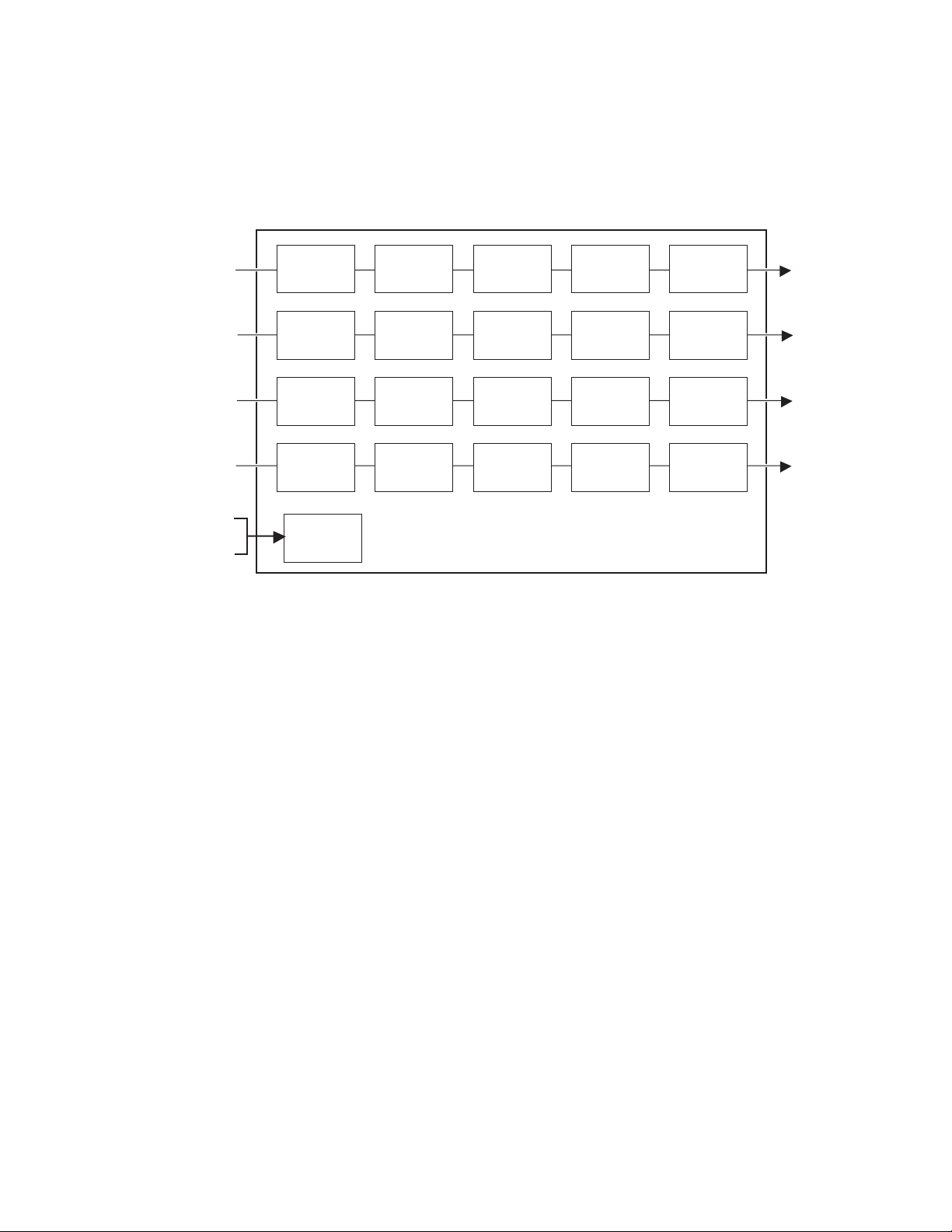
Functional Description
NTSC/PAL 1
NTSC/PAL 2
NTSC/PAL 3
NTSC/PAL 4
Timing
Timing
Timing
Timing
Reference
Looping
Reference Input
SDI 1
SDI 2
SDI 3
SDI In
SDI In
SDI In
SDI In
SDI 4
Video
Proc
Video
Proc
Video
Proc
Video
Proc
Composite
Out
Composite
Out
Composite
Out
Composite
Out
VBI
VBI
VBI
VBI
A block diagram of the 8964ENC front module is shown in Figure 33.
Figure 33. 8964ENC Front Module Block Diagram
Functional Description
8964ENC/-FS — Instruction Manual 67
Page 68

Functional Description
68 8964ENC/-FS — Instruction Manual
Page 69

Configuration Summary
Ta bl e 8 provides a complete summary of the 8964ENC functions and a
comparison of the functionality available with each control type along with
the ranges and default values for each parameter.
Table 8. Summary of 8964ENC/-FS Configuration Functions
Function
Typ e
OSD (On Screen Display) Off On/Off
Horizontal Timing 0
Fine Phase 0
Vertical Timing 0
Freeze Type AutoBlue
Test Signal Generator Off On/Off
Chroma Kill Off On/Off
Black Clip control None
Saturation/Chroma Gain 100
Hue/Chroma Phase 0
Brightness/Y Offset 0
Contrast/Y Gain 100
Burst disable On On or Off
Output Video Gain 100
Add setup to active video On On/Off
Reserve VBI lines for data None
Default
Range/Choices
Resolution
0 - 857.5 pixels (525)
0 - 863.5 pixels (625)
(0.5 pixel steps)
0-100
(1% steps)
0 – 524 lines (525)
0 – 624 lines (625)
(1line steps)
AutoFrz, AutoBlue
Field 1, Field 2, or
Frame
None, -11%, -6%
or -1.5%
50–150%
(0.8% steps)
± 22.3 degrees
(0.2 degree steps)
± 7.5%
(0.5% steps)
50–149.6%
(0.4% steps)
61-138.5%
(0.5% steps)
See VBI Web Page on
page 47
Web Page/
Function Name
OSD Control/
On Screen Display
Timing/
Horizontal Timing (pixels)
Timing/
Fine Phase Adjustment (%)
Timing/
Vertical Timing (lines)
Timing/Freeze Mode
Select AutoFrz, AutoBlue,
Field 1, Field 2, or Frame
radio button
Video Proc/
Select Enable or Color Bars
radio button
Video Proc/
Chroma Kill checkbox
Video Proc/
Select None, -11%, -6% or -
1.5% radio button
Video Proc/
Saturation/Chroma Gain (%)
Video Proc/
Hue/Chroma Phase (deg)
Video Proc/
Brightness/Y Offset (mV)
Video Proc/
Contrast/Y Gain (%)
Video Proc/
Burst checkbox
Composite Out/
Output Video Gain
Composite Out/
Add setup to active video check-
box
VBI/
Select data line pair buttons
Function Switch
Bank/Setting
No local control BlkClip1-4
1:1 N/A
2:B HTim 1-4
2:A FPhase1-4
2:C VTim1-4
2:D
2:E
2:F
1:C Tst1-4
1:B Chroma1-4
1:8 ChroGn1-4
1:9 ChroPhs1-4
1:7 YOff1-4
1:6 YGn1-4
1:D Burst1-4
1:4 OutGn1-4
1:2 N/A
2:1/2:2/2:3
See Table 6 on
page 31
Control
Panel
Mnemonic
Frez1-4
N/A
Notes/
Conditions
Jumper JP3
must be enabled
on module.
8964ENC or
8964ENC-FS
8964ENC-FS
only.
Video
processing
controls
Composite out
controls. Setup
state affects VBI
setup control.
See Table 4 on
page 23 for line
choices
8964ENC/-FS — Instruction Manual 69
Page 70

Configuration Summary
Table 8. Summary of 8964ENC/-FS Configuration Functions
Function
Typ e
Blank VBI Lines On On/Off
Add VBI Setup (525 only) On On/Off
Picture Enhancer process Disable
Picture Enhancer split
screen
PE Detail Enhancer Level 0 0-255
PE Overshoot Protection 0 0-7
Noise Reducer process Off On/Off
Noise Reducer filter select
Noise Reducer level 0
Noise Reducer threshold 0
Learn/Recall E-MEM N/A E-MEM 1-5
Recall factory defaults N/A See Defaults column
Default
Off On/Off
3.5 MHz
Notch
Range/Choices
Resolution
Bypass/Disable/
Enable
3.5 MHz Low Pass
4.2 MHz Notch
3.5 MHz Notch
2.8 MHz Notch
0-8
(1.0 steps)
0-10
(1.0 steps)
Web Page/
Function Name
VBI/
Blank VBI/Data Line Pair or use
Blank All or Pass All button
VBI/
VBI Setup checkbox
(grayed out when Active Video
Setup is off)
Picture Enhancer/
Select Bypass/Disable or Enable
button
Picture Enhancer/
Select Split Screen checkbox
Picture Enhancer/
Detail Enhancer Level
Picture Enhancer/
Overshoot Protection
Noise Reducer/
Select Enable Noise Reducer
checkbox
Noise Reducer/
Select Filter Select button
Noise Reducer/
Level
Noise Reducer/
Threshold
E-MEM/
Standard View: Recall 1-5
Advanced View: Recall/Learn
/Save to/Load from
E-MEM/
Recall factory settings button
Function Switch
Bank/Setting
2:4 N/A
2:5 N/A
3:B
Disable/Bypass
3:C
Enable/Disable
3:D N/A
3:E N/A
3:F N/A
3:8 N/A
No local control N/A
3:9 N/A
3:A N/A
1:E N/A
1:F N/A
Mnemonic
PicEnh1-4
Control
Panel
Notes/
Conditions
Line selectable in
Remote.
Global in Local.
Active Video
Setup in Composite Out must
be enabled.
Picture Enhancer
enabled
Noise
Reducer
enabled
E-MEM
functions
70 8964ENC/-FS — Instruction Manual
Page 71

Index
Numerics
2ND LED 19, 27
8900 frame
module capacity
8900NET (Net Card) module
general
installation 11
software requirements 11, 35
8900V-R rear module 10, 13
8964ENC
features
33
9
A
AutoBlue
control summary
local controls 31
overview 21
remote control 45
AutoFreeze
control summary
local controls 31
overview 21
remote control 45
B
backplane 12
black clip
control summary
overview 24
remote control 49
blank rear cover 14
Block diagram 67
Burst
control summary
local control 31
overview 24
remote control 49
10
69
69
69
69
C
cabling
inputs
outputs 17
reference input 17
CH1-4 LEDs 19
chroma gain (saturation)
control summary
local control 31
overview 24
remote control 49
Chroma Kill
control summary
description 24
local control 31
remote control 49
chroma phase (hue)
control summary
local control 31
overview 24
remote control 49
Clear button 59
Clear Errors button 43
CM0 LED 19, 27
channel indication table 28
CM1 LED 19, 27
channel indication table 28
Coarse adjust button
overview
color frame output 26
COMM LED 19
composite output
adjustment overview
composite video outputs 17
CONF LED 19, 27
configuration
control summary
Local, onboard 27
overview 20
connectors 12
Control panel 33
17
69
69
69
36
25
69
8964ENC/-FS — Instruction Manual 71
Page 72

Index
control panel
mneumonics
CSM LED 19, 27
69
D
data line pairs
control summary
description 23
local configuration 31
remote configuration 47
documentation online 4
69
E
E-MEM
Advanced view
description 53
load from file 56
local controls 31
save to file 55
standard view 53
web page 53
environmental 63
54
Frame Sync
control summary
local controls 31
option features 20
remote control 45
upgrade 61
freeze modes 21
frequently asked questions 4
front module
installation
Function rotary switch
accessing banks
settings table 31
Functional View web page 41
fuse 66
69
15
27
G
Gecko 8900 frame 10, 63
GeckoFlex frame 13, 63
frame alarm 64
graphical user interface (GUI) 37
Grass Valley web site 4
F
factory defaults 18
control summary 69
recall factory defaults
local control
remote control 53
Factory names
53
recall
FAQ database 4
FAULT LED
states
19
Fine adjust button
overview
fine phase
control summary
local controls 31
overview 20
remote control 44
Frame Controller module 11
Frame Health Reporting 60
Frame Status web page 65
31
36
69
H
horizontal timing
control summary
local controls 31
overview 20
remote control 44
69
I
I/O Config web page 40
inputs
cabling
specification 62
installation
8900V-R rear module
front module 15
precautions 13
Internet Explorer 35
17
J
jitter
14
72 8964ENC/-FS — Instruction Manual
Page 73

Index
reference input 25
Jumpers
onboard
29
L
LEDs
front edge
Names and Meanings table 19
line categories
defined
Locate Module function 59
loop-through 17
18
22
M
manual freeze
control summary
local control 31
overview 21
remote control 45
module
12
slots
Module Health Bus 64
module installation precautions 13
Module Status web page 65
69
N
NetConfig PC application
required for updating software
Newton control panel 33
Noise Reducer
control summary
local controls 32
overview 25
remote control 51
web page 51
70
O
online documentation 4
operating system 35
OSD (On Screen Display)
enable with onboard jumper
local control 31
remote control 57
29
61
summary table 69
output video gain
control summary
local control 31
overview 25
remote control 52
outputs
composite video
specification 62
69
17
P
Picture Enhancer
control summary
description 21
local controls 32
remote control 46
split screen 21
web page 46
power 63
PWR LED 19
70
R
rear connectors 12
rear module
installation precautions
rear retainer clip
screw torque specification
reference input
cabling
jitter 25
Refresh button 36
repair depot 66
Restore upon Install checkbox 59
17
13
63
S
SDI IN In web page 43
serial digital inputs 17
setup
active video
control summary
local control 31
overview 25
remote control 52
VBI
69
8964ENC/-FS — Instruction Manual 73
Page 74

Index
control summary 70
local control 31
overview 23
Slot Config web page 58
slot memory 59
SNMP reporting
enabling SNMP Trap Reports
overview 65
software download from web 4
software updating 61
split screen
Picture Enhancer
Status LED icon 36
status monitoring 64
Status web page 38
switches
onboard control
21
27
T
termination 17
test signal generator
control summary
local control 31
overview 24
remote control 49
testpoints 66
Timing web page 44
troubleshooting 66
69
U
upgrade
Frame Sync
61
V
60
programmable lines 23
vertical timing
control summary
local controls 31
overview 20
remote control 45
Video Proc web page 49
video processing
control summary
local controls 31
overview 24
remote controls 49
voltage 63
voltage tespoints 66
69
69
W
web browser
overview
recommended 35
web site
documentation
FAQ database 4
Grass Valley 4
software download 4
34
4
Y
Y gain (contrast)
control summary
local control 31
overview 24
remote control 49
Y offset (brightness)
control summary
local control 31
overview 24
remote control 49
69
69
VBI setup
control summary
overview 23
remote control 47
VBI web page 47
vertical blanking interval (VBI)
adding setup
blanking 23
line categories 22
74 8964ENC/-FS — Instruction Manual
70
23
 Loading...