

Page 1
8964DEC/-FS
4-CH NTSC/PAL TO SDI DECODER MODULE
Instruction Manual
SOFTWARE VERSION 1.0.5
071820802
JULY 2004
Page 2

Contacting Grass Valley
Region Voice Fax Address Web Site
North America (800) 547-8949
Support: 530-478-4148
Pacific Operations +852-2585-6688
Support: 852-2585-6579
U.K., Asia, Middle East +44 1753 218 777 +44 1753 218 757
France +33 1 45 29 73 00
Germany, Europe +49 6150 104 782 +49 6150 104 223
Copyright © Thomson Broadcast and Media Solutions All rights reserved.
Grass Valley Web Site
Sales: (530) 478-3347
Support: (530) 478-3181
+852-2802-2996
Grass Valley
P.O. Box 599000
Nevada City, CA 959597900 USA
www.thomsongrassvalley.com
The www
Online User Documentation
.thomsongrassvalley.com web site offers the following:
— Current versions of product catalogs, brochures,
data sheets, ordering guides, planning guides, manuals, and release notes
in .pdf format can be downloaded.
FAQ Database
— Solutions to problems and troubleshooting efforts can be
found by searching our Frequently Asked Questions (FAQ) database.
Software Downloads
— Software updates, drivers, and patches can be down-
loaded.
2 8964DEC/-FS Instruction Manual
Page 3

Contents
Preface
. . . . . . . . . . . . . . . . . . . . . . . . . . . . . . . . . . . . . . . . . . . . . . . . . . . . . . . . . . . . . . . . . . . . . 5
About This Manual . . . . . . . . . . . . . . . . . . . . . . . . . . . . . . . . . . . . . . . . . . . . . . . . . . . . . 5
8964DEC 4-Channel
NTSC/PAL to SDI Decoder
Introduction . . . . . . . . . . . . . . . . . . . . . . . . . . . . . . . . . . . . . . . . . . . . . . . . . . . . . . . . . . . 7
Installation . . . . . . . . . . . . . . . . . . . . . . . . . . . . . . . . . . . . . . . . . . . . . . . . . . . . . . . . . . . . 8
Frame Capacity . . . . . . . . . . . . . . . . . . . . . . . . . . . . . . . . . . . . . . . . . . . . . . . . . . . . . . 8
Module Placement in the Gecko 8900 Frame . . . . . . . . . . . . . . . . . . . . . . . . . . . . . 8
Cabling . . . . . . . . . . . . . . . . . . . . . . . . . . . . . . . . . . . . . . . . . . . . . . . . . . . . . . . . . . . . 10
Inputs. . . . . . . . . . . . . . . . . . . . . . . . . . . . . . . . . . . . . . . . . . . . . . . . . . . . . . . . . . . . 10
Outputs . . . . . . . . . . . . . . . . . . . . . . . . . . . . . . . . . . . . . . . . . . . . . . . . . . . . . . . . . . 10
Reference Loop-through Input . . . . . . . . . . . . . . . . . . . . . . . . . . . . . . . . . . . . . . 10
Power Up . . . . . . . . . . . . . . . . . . . . . . . . . . . . . . . . . . . . . . . . . . . . . . . . . . . . . . . . . . . . 11
Operation Indicator LEDs . . . . . . . . . . . . . . . . . . . . . . . . . . . . . . . . . . . . . . . . . . . . 11
Configuration. . . . . . . . . . . . . . . . . . . . . . . . . . . . . . . . . . . . . . . . . . . . . . . . . . . . . . . . . 13
Configuration Summary. . . . . . . . . . . . . . . . . . . . . . . . . . . . . . . . . . . . . . . . . . . . . . 13
Video Processing Controls . . . . . . . . . . . . . . . . . . . . . . . . . . . . . . . . . . . . . . . . . . 13
Video Timing and Freeze Controls . . . . . . . . . . . . . . . . . . . . . . . . . . . . . . . . . . . 17
Picture Enhancer Controls . . . . . . . . . . . . . . . . . . . . . . . . . . . . . . . . . . . . . . . . . . 17
Local Onboard Module Configuration. . . . . . . . . . . . . . . . . . . . . . . . . . . . . . . . . . 20
Configuration Switches and Controls. . . . . . . . . . . . . . . . . . . . . . . . . . . . . . . . . 20
Onboard Jumpers. . . . . . . . . . . . . . . . . . . . . . . . . . . . . . . . . . . . . . . . . . . . . . . . . . 22
8964DEC Module Onboard Configuration Settings . . . . . . . . . . . . . . . . . . . . . 23
Remote Configuration and Monitoring . . . . . . . . . . . . . . . . . . . . . . . . . . . . . . . . . 26
8964DEC Links and Web Pages . . . . . . . . . . . . . . . . . . . . . . . . . . . . . . . . . . . . . . 28
Status Web Page. . . . . . . . . . . . . . . . . . . . . . . . . . . . . . . . . . . . . . . . . . . . . . . . . . . 29
I/O Config Web Page . . . . . . . . . . . . . . . . . . . . . . . . . . . . . . . . . . . . . . . . . . . . . . 31
Functional View Web Page. . . . . . . . . . . . . . . . . . . . . . . . . . . . . . . . . . . . . . . . . . 32
EDH Insertion. . . . . . . . . . . . . . . . . . . . . . . . . . . . . . . . . . . . . . . . . . . . . . . . . . . . . 32
Module Configuration Web Pages . . . . . . . . . . . . . . . . . . . . . . . . . . . . . . . . . . . 33
E-MEM Web Page . . . . . . . . . . . . . . . . . . . . . . . . . . . . . . . . . . . . . . . . . . . . . . . . . 43
OSD Control Web Page. . . . . . . . . . . . . . . . . . . . . . . . . . . . . . . . . . . . . . . . . . . . . 47
Slot Config Web Page . . . . . . . . . . . . . . . . . . . . . . . . . . . . . . . . . . . . . . . . . . . . . . 48
Software Update Web Page . . . . . . . . . . . . . . . . . . . . . . . . . . . . . . . . . . . . . . . . . 50
Newton Control Panel Configuration . . . . . . . . . . . . . . . . . . . . . . . . . . . . . . . . . . 51
Module Option Upgrade . . . . . . . . . . . . . . . . . . . . . . . . . . . . . . . . . . . . . . . . . . . . . . . 51
Specifications . . . . . . . . . . . . . . . . . . . . . . . . . . . . . . . . . . . . . . . . . . . . . . . . . . . . . . . . . 52
Service. . . . . . . . . . . . . . . . . . . . . . . . . . . . . . . . . . . . . . . . . . . . . . . . . . . . . . . . . . . . . . . 54
Status Monitoring . . . . . . . . . . . . . . . . . . . . . . . . . . . . . . . . . . . . . . . . . . . . . . . . . . . . . 55
LEDs . . . . . . . . . . . . . . . . . . . . . . . . . . . . . . . . . . . . . . . . . . . . . . . . . . . . . . . . . . . . . . 55
Frame Alarm . . . . . . . . . . . . . . . . . . . . . . . . . . . . . . . . . . . . . . . . . . . . . . . . . . . . . . . 56
Web Browser Interface . . . . . . . . . . . . . . . . . . . . . . . . . . . . . . . . . . . . . . . . . . . . . . . 56
8964DEC/-FS Instruction Manual 3
Page 4

Contents
SNMP Reporting . . . . . . . . . . . . . . . . . . . . . . . . . . . . . . . . . . . . . . . . . . . . . . . . . . 57
Index
. . . . . . . . . . . . . . . . . . . . . . . . . . . . . . . . . . . . . . . . . . . . . . . . . . . . . . . . . . . . . . . . . . . . . . 59
4 8964DEC/-FS Instruction Manual
Page 5

Preface
About This Manual
This manual describes the features of a specific module of the Gecko 8900
Signal Processing System. As part of this module family, it is subject to
Safety and Regulatory Compliance described in the Gecko 8900 Series
frame and power supply documentation (see the
Frames Instruction Manual
8900TX/8900TF/8900TFN
).
8964DEC/-FS Instruction Manual 5
Page 6

Preface
6 8964DEC/-FS Instruction Manual
Page 7

8964DEC 4-Channel NTSC/PAL to SDI Decoder
Introduction
The 8964DEC module offers four independent, full-function, high density
decoders on one module. With 10-bit A-to-D and full-adaptive decoding,
the 8964DEC provides high quality conversion of NTSC/PAL video into a
broadcast quality component 4:2:2 signal from even the noisiest inputs
such as satellite and microwave links. A frame synchronization option is
also available.
The 8964DEC features:
•4 NTSC/PAL to 270 Mbs SDI decoders with independent controls for:
• Line sync mode for horizontal timing,
• Frame sync (option) adding vertical timing and freeze modes,
•Automatic gain and chroma controls (AGC and ACC),
•Monochrome In signal support,
•Processing amplifier,
• Line-by-line VBI processing with remote control,
•Test signal generator (color bars and pathological signal outputs),
•EDH insertion for error tracking, and
• Picture detail enhancement.
•User adjustable 2D adaptive comb decoding,
•An OSD (On Screen Display) can be keyed in and out of video output,
•Analog color black NTSC/PAL reference inputs,
•Up to 10 8964DEC decoders in a 2 RU Gecko™ 8900 video frame providing up to 40 decoders in one frame, and
•Remote interface with the 8900NET module (version 3.2.0 or later):
•Web browser configuration and control,
•SNMP traps for use with NetCentral, and
•Control panel connections.
8964DEC/-FS Instruction Manual 7
Page 8

Installation
Installation
Frame Capacity
1.
2.
Installation of the 8964DEC module is a process of:
The 8964DEC module can be plugged in and removed from a Gecko 8900
video frame with power on. When power is applied to the module, LED
indicators reflect the initialization process (see
The 8964DEC module can be installed in all Gecko 8900 video frames but
with varying maximum quantities determined by frame cooling capacity.
Table 1 provides the power capacity, cooling capacity, and maximum
module count for each frame type.
Placing the module in the proper frame slot, and
Cabling and terminating signal ports.
Power Up
on page 11).
Table 1. Video Frame Power Capacity
Capacity Calculated 8900TX Frame 8900TF Frame 8900TFN Frame
Power (W) 100 100 100
Recommended Module Cooling (W) 30 90 90
8964DEC (-FS) Modules 5 10 10
Note
Module capacity figures assume no other modules are in the frame.
X = Not recommended without forced air cooling.
Module Placement in the Gecko 8900 Frame
There are ten cell locations in the frame to accommodate either analog or
digital modules. These are the left ten locations. Refer to Figure 1 on page 9.
The two cells on the right are allocated for the power supplies. For additional information concerning the Power Supply module, refer to the 8900
Power Supply manual.
The third cell from the right is allocated for the Frame Monitor or 8900NET
Network Interface module. These modules provide health monitoring and
control options.
Note
8 8964DEC/-FS Instruction Manual
If using an 8900NET module in the frame, it must be running software
version 3.2.0 or higher for proper remote operation of the 8964DEC module.
Page 9
1.
2.
3.
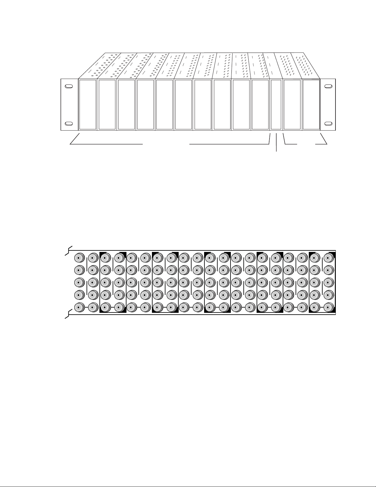
Figure 1. Gecko 8900 Series Frame
Installation
8208_04r1
DA10
J1 J2
O
J3 J4
U
T
J5 J6
J7 J8
J9 J10
IN
DA9
J1 J2
J2
O
J3 J4
J4
U
T
J5 J6
J6
J7 J8
J8
J9 J10
IN
Any 8900 Module
Power
Supplies
Frame Controller or
(only)
8900NET Network
Interface Module
8900 module slots are interchangeable within the frame. There are 10 BNC
connectors in each slot’s I/O group. The functional assignment of each connector in a group is determined by the module that is placed in that slot.
The maximum number of modules a Gecko 8900 frame can accept is ten.
Figure 2 illustrates the rear connector plate for a Gecko 8900 frame.
Figure 2. Gecko 8900 Series Frame Rear Connector
DA8
J1 J2
O
J3 J4
U
T
J5 J6
J7 J8
J9 J10
IN
DA7
J1 J2
J2
O
J3 J4
J4
U
J5 J6
J6
J7 J8
J8
J9 J10
IN
T
DA6
J1 J2
O
J3 J4
U
T
J5 J6
J7 J8
J9 J10
IN
DA5
J1 J2
J2
O
J3 J4
J4
U
T
J5 J6
J6
J7 J8
J8
J9 J10
IN
DA4
J1 J2
O
J3 J4
U
T
J5 J6
J7 J8
J9 J10
IN
DA3
J2
J1 J2
O
J4
J3 J4
U
T
J6
J5 J6
J8
J7 J8
J9 J10
IN
DA2
J1 J2
O
J3 J4
U
T
J5 J6
J7 J8
J9 J10
IN
DA1
J1 J2
O
J3 J4
U
T
J5 J6
J7 J8
J9 J10
IN
0543-03
To install a module in the frame:
Insert the module, connector end first, with the component side of the
module facing to the right and the ejector tab to the top.
Verify that the module connector seats properly against the backplane.
Press in the ejector tab to seat the module.
8964DEC/-FS Instruction Manual 9
Page 10
Installation
Cabling
Cabling to and from the module is done at the back of the Gecko 8900
frame.
Note
At the back of every hard cover manual are overlay cards that can be placed
over the rear connector BNCs to identify the specific 8964DEC connector
functions.
Inputs
Four analog composite video inputs are provided at BNCs J1, J3, J5, and J7.
The inputs are non-looping and internally terminated.
Note
If feeding a monochrome signal to a channel, select Monochrome In with the
Composite In controls. Refer to Table 5 on page 18 control summary.
Outputs
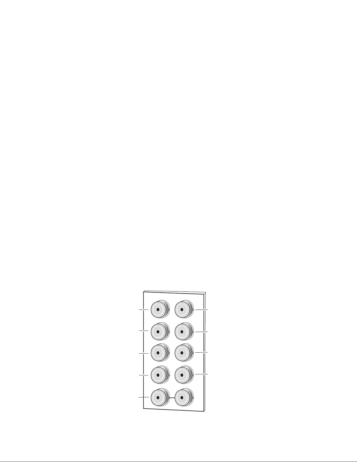
Four corresponding serial digital video outputs are provided at BNCs J2,
J4, J6, and J8 as shown in Figure 3. There is no audio tracking output on the
output of the module.
Reference Loop-through Input
Connect an NTSC/PAL analog color black reference source to one of the
loop-through reference connectors, J9 or J10. Terminate the unused connector into 75
Ω if the signal is not looped to other equipment.
Note
Figure 3. 8960 Input/Output Connectors
Reference In
(loop-through)
The line rate for the module (all four decoder channels) will be auto-detected
from the Reference In signal.
X
CV In 1
J1
CV In 2
J3
CV In 3
J5
CV In 4
J7
J9 J10
IN
J2
J4
J6
J8
SDI Out 1
J2
SDI Out 2
J4
SDI Out 3
J6
SDI Out 4
J8
8208_02
10 8964DEC/-FS Instruction Manual
Page 11
Power Up
Operation Indicator LEDs
Power Up
The front LED indicators and configuration switches are illustrated in
Figure 4. Upon power-up, the green PWR LED should light and the yellow
CONF LED should illuminate for a few seconds for the duration of module
initialization.
With factory default configuration and a valid input signal connected, the
green PWR LED and one of the green signal standard LEDs (525 or 625)
should illuminate (refer to Table 2 on page 12 to see the possible operating
indicator combinations).
Video input presence on each decoder channel is indicated by the
CH1–CH4 green LEDs on.
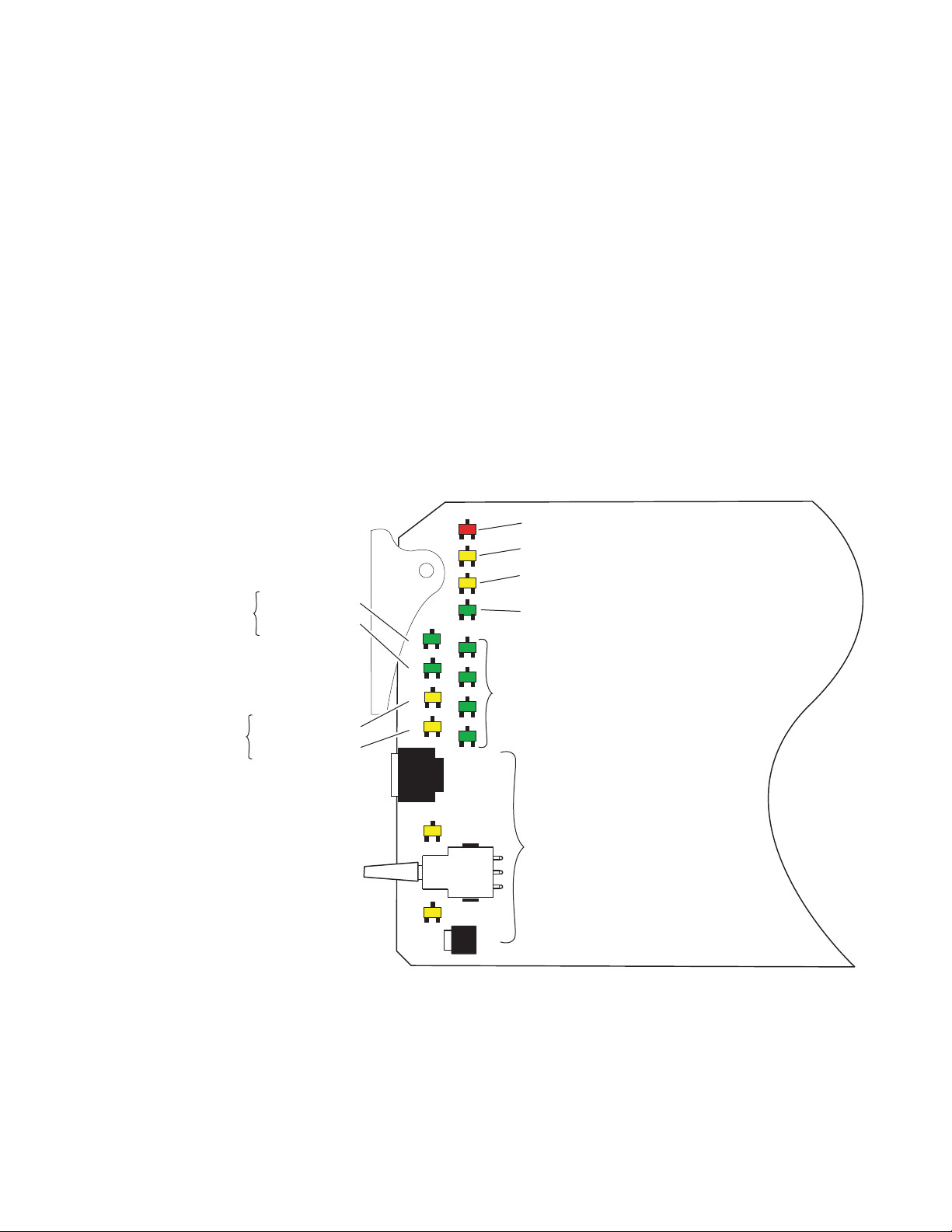
Figure 4. LEDs and Configuration Switches
One LED will be
on to indicate
525 or 625 line
reference is present
525 – Green LED
625 – Green LED
Module Configuration
Active Channel
Control Indictors
CM1 – Yellow LED
CM0 – Yellow LED
525 625 CM1 CM0
FUNCTION
2ND
UP
DOWN
CSM
FAULT
COMM CONF PWR
CH1 CH2 CH3 CH4
2ND LED
FAULT – Red LED is off during normal operation.
COMM – Yellow LED on indicates frame bus traffic.
CONF – Yellow LED on indicates module is initiating,
changing operating mode, or updating firmware.
PWR – Green LED on indicates power OK.
CH 1 – CH4 Green LEDs on indicates
signal present on CH1, 2, 3 and 4.
Module Configuration Switches and LEDs.
8964DEC/-FS Instruction Manual 11
8208_05
Page 12

Power Up
Table 2. Board Edge LED Names and Meaning
LED Indication Condition
Off Normal operation.
FAULT
(red)
COMM
(yellow)
CONF
(yellow)
PWR
(green)
625
(green)
525
(green)
CM1
(yellow)
CM0
(yellow)
CH1
(green)
CH2
(green)
CH3
(green)
CH4
(green)
2ND
(yellow)
CSM
(yellow)
On continuously Module has detected an internal fault. (Refer to Service on page 54.)
Flashing Configuration problems. Check inputs and settings. Missing video.
Off No activity on frame communication bus.
3 Quick Pulses Locate Module command received by the module from a remote control system.
Short flash Activity present on the frame communication bus.
Off Module is in normal operating mode.
On continuously Module is initializing, changing operating modes or updating firmware.
3 Quick Pulses Locate Module command received by the module from a remote control system.
Off No power to module or module’s DC/DC converter failed.
On continuously Normal operation, module is powered.
Off No reference or standard is other than 625.
On continuously Valid 625 video reference is present.
Off No reference or standard is other than 525.
On continuously Valid 525 video reference is present.
Off
On
Off
On
Off No signal present on Ch 1 or input signal line rate does not match reference.
On continuously Valid signal is present on Channel 1.
Off No signal present on Ch 2 or input signal line rate does not match reference.
On continuously Valid signal is present on Channel 2.
Off No signal present on Ch 3 or input signal line rate does not match reference.
On continuously Valid signal is present on Channel 3.
Off No signal present on Ch 4 or input signal line rate does not match reference.
On continuously Valid signal is present on Channel 4.
Off Rotary switch is addressing Bank 1 configuration functions.
On continuously Rotary switch is addressing Bank 2 configuration functions.
Flashing Rotary switch is addressing Bank 3 configuration functions.
Off Paddle switch controls current Bank parameter mode.
On continuously Paddle switch controls channel selection.
On/Off combination Indicates what channel is enabled for configuration when
Channel Select Mode (CSM) LED is on (described in Table 6 on page 21).
12 8964DEC/-FS Instruction Manual
Page 13

Configuration
The 8964DEC can be configured locally using onboard switches or
remotely using the 8900NET network interface GUI or a networked control
panel.
Refer to the following sections for configuration instructions:
•Configuration Summary (page 13)
• Local Onboard Module Configuration (page 20)
•Remote Control and Monitoring (page 26)
•Control Panel Configuration (page 51)
Operation of these control types is explained in detail in their respective
sections of this manual.
Configuration
Configuration Summary
This section provides a summary of all parameters that can be configured
on the 8964DEC module. The video processing configuration is described
by what line types will be affected by the adjustments or choices made. Use
this section in conjunction with the specific configuration method instructions for each configuration type. Table 5 on page 18 provides a summary
in table format of all parameters and their ranges, default values, and
remote, local, and control panel function names and locations for setting
each value.
Video Processing Controls
The 8964DEC provides video processing controls for the decoding process
for all four channels independently. How the video data is processed
depends on what line the video is on. Some processing affects all lines,
other processing affects just the active picture lines, programmable VBI
lines or the fixed VBI lines.
Line Categories
The line categories used in the configuration of the video signal for the
8964DEC are defined as follows:
• F_Active Lines – the portion of the active video that is fixed and always
treated by the module as carrying active video (not programmable).
• P_Active Lines – lines in the active video that can be configured by the
user to carry either active video or be reserved for carrying user data.
8964DEC/-FS Instruction Manual 13
Page 14

Configuration
• CVBI – the lines in the vertical interval that can be configured by the
user.
•FVBI – the line in the vertical blanking interval that are fixed and are not
configurable.
The line numbers for each category above are defined in Table 3 for both
525 and 625 line rates on the 8964DEC module.
Table 3. Line Numbers for 8964DEC Line Categories
Line Categories
Label
F_Active
P_Active
CVBI
FVBI
Start End Start End
25 (F1)
288 (F2)
21 (F1)
284 (F2)
10 (F1)
273 (F2)
1 (F1)
264 (F2)
525 625
263 (F1)
525 (F2)
24 (F1)
287 (F2)
20 (F1)
283 (F2)
9 (F1)
272 (F2)
29 (F1)
342 (F2)
24 (F1)
337 (F2)
6 (F1)
319 (F2)
624 (F1)
311 (F2)
310 (F1)
623 (F2)
28 (F1)
341 (F2)
23 (F1)
336 (F2)
5 (F1)
318 (F2)
Note
The categories may not match the line definition as specified in the applicable
standard.
Line pairs in the P_Active line category can be reserved for carrying data
by configuring Data Line Pairs with local or remote controls. Refer to
Table 4 for a listing of the Data Line Pairs lines that are available with each
setting.
Table 4. Lines Reserved for Carrying Data
525 Line
Selection
None None None None
21/284 21/284 24/337 24/337
22/285 21/284 – 22/285 25/338 24/337 – 25/338
23/286 21/284 – 23/286 26/339 24/337 – 26/339
24/287 21/284 – 24/287 27/340 24/337 – 27/340
Data Line Pairs
Reserved
625 Line
Selection
28/341 24/337 – 28/341
Data Line Pairs
Reserved
All Lines – Composite In Video Path Processing
The incoming video composite signal path for each channel can be processed before decoding. These processing functions affect all lines of video
at once, both active picture lines and VBI lines.
14 8964DEC/-FS Instruction Manual
Page 15

Configuration
The following processing functions are available for the video composite
input signals:
• AGC and ACC on or off – the Auto Gain Control (AGC) and Auto
Chroma Control (ACC) are set to default to the off condition (
ACC
and
provides the following controls for video and chroma gain:
• Input Video Gain – adjust the input video gain in percent relative to
checkboxes not checked). This is the recommended state and
100% (100% = 1 V p-p). AGC operation is based on sync tip.
Enable AGC
Note
•Monochrome In – check this box when a monochrome input signal (or
Manually adjusting Input Video Gain may shift picture position slightly
(± 1 clock).
• Input Chroma Gain – adjust the percentage of chroma gain relative
to 100%.
Checking the
respective automatic gain settings.
any signal that does not contain burst) is being fed to a channel. This
chechbox must be checked for the module to recognize the signal as
valid and light the corresponding input LED. This will also enable the
Chroma Kill function on the Video Proc page, changing it to a read-only
state.
Enable AGC
Enable ACC
or
checkbox will enable the
Active Picture Lines – Video Path Processing
The video processing functions described below affect all active picture
lines (F_Active lines and the P_Active the user has chosen to be part of the
active picture).
The available video path processing controls are the following:
•Contrast/Y Gain – adjusts the percentage of luminance relative to
white.
• Saturation/Chroma Gain – adjusts percentage of saturation and
chroma gain relative to 100% saturation.
• Brightness/Y Offset – adjusts amount of brightness/Y offset in mV.
•Hue/Chroma Phase – adjusts hue/chroma phase in degrees for both
line rates (525 and 625).
•Remove Setup – set to
YES
when setup is present (NTSC). Available in 525 mode only.
• TSG (100% Color Bars) – when on, enables the internal test signal generator to output a 100% Color Bars test signal to the channel output.
• TSG (Pathological) – when on, enables the internal test signal generator
to output a Pathological test signal to the channel output.
Note
8964DEC/-FS Instruction Manual 15
Test signals are not adjustable in the Video Processing controls.
NO
when no setup is present (Japanese NTSC), or
Page 16

Configuration
•On Screen Display (OSD) – enables or disables the On Screen Display
on the selected channel output. Jumper JP3 on module must be set to
enable control. Refer to
on page 23.
•Chroma Kill – removes all chroma from the signal (black and white).
This is a global control, affecting chroma on all lines of active video and
includes the VBI.
•EDH insertion – allows EDH to be inserted in any of the four channel
outputs (available in Remote mode only).
•Decode Mode – select the type of decoding (filtering) for each input
from comb adaptive, comb non-adaptive or notch. Adaptive decoding
is 3-line in NTSC and 4-line in PAL.
8964DEC Module Onboard Configuration Settings
Programmable VBI and Active Picture Lines – Composite Input
Programmable lines in the composite input vertical blanking interval
include the configurable VBI lines (CVBI). Programmable active picture
lines (P_Active) are the lines reserved for carrying data (Data Lines) (refer
to Table 4 on page 14). Both of these line pair types can be configured for
the following:
•Decode Mode – select from Notch Decode or Pass Through (blank U
and V). (Global control – all line pairs are affected in the same manner.)
Note
•Chroma Kill – removes all chroma on VBI and P_Active lines reserved
Note
•Remove Setup from VBI – with local onboard controls, select YES to
Note
• Blank – in local mode, select YES to blank all lines of CVBI or NO to not
When Notch Decode is selected, active picture lines reserved for data are
actually comb decoded with potential artifacts.
for data. (Global control – all line pairs are affected in the same manner.)
This control has no affect when Chroma Kill is already enabled on the Video
Proc web page.
remove setup or NO to not remove setup from all lines of CVBI (global).
In remote mode on the web page, setup can be removed on a
line-by-line basis.
When
Remove Setup from active video
posite In web page (No removal), the VBI Setup Removal function will have
no affect.
blank. In remote mode, lines can be blanked on a line-by-line basis with
the web page (toothed blanking).
is not selected on the Video Com-
16 8964DEC/-FS Instruction Manual
Page 17

Video Timing and Freeze Controls
With a standard 8964DEC module with no Frame Sync enabled the following Line Sync timing adjustment is available:
•Horizontal Timing – adjusts the horizontal delay on the channel output
in pixels. This will add an additional delay of up to one line.
With an 8964DEC-FS module (8964DEC with Frame Sync enabled, see
Module Option Upgrade on page 51), the following Frame Sync timing
adjustments can be made:
•Horizontal Timing – identical to the line sync timing above.
•Vertical Timing – adjusts vertical delay in line increments.
Also available with the 8964DEC-FS are the following freeze controls:
•None – when signal is lost, no automatic freeze occurs and no manual
freeze is activated.
•AutoBlue – when AutoBlue is enabled on a channel, the output will
automatically freeze to a blue screen when the input signal is lost on
that channel.
Configuration
•AutoFreeze – when AutoFreeze is enabled on a channel, the output will
automatically freeze on the last valid field when the input signal is lost
on that channel.
• Field 1 – manually freezes the output signal on field 1 of the last frame.
• Field 2 – manually freezes the output signal on field 2 of the last frame.
• Frame – manually freezes the output signal on the last frame.
A field freeze provides less resolution and no motion artifacts in the output.
In frame mode, the resolution is higher since both fields are present, but the
presentation of the two fields can cause motion artifacts.
Picture Enhancer Controls
The Picture Enhancer feature is standard on the 8964DEC and 8964DEC-FS
modules. This feature allows separate picture enhancement control on each
channel output. Picture enhancement affects all lines of video.
Use the following controls for picture enhancement:
•Disable – the Picture Enhancer process can be turned off by selecting
Disable.
• Picture enhancement can be enabled by selecting one of three settings,
Low, Medium, or High. Amount of adjustment will depend on picture
type and noise level.
8964DEC/-FS Instruction Manual 17
Page 18

Configuration
Table 5 provides a complete summary of the 8964DEC processing functions
and a comparison of the functionality available with each control type
along with the ranges and default values for each parameter. The table is
organized to provide a breakdown of the video path processing adjustments by specific grouping of line type in the video signal.
Table 5. Summary of 8964DEC Configuration Functions By Line Type
Processing
Function
Type
All Lines, Channels 1–4. Composite In Video Path Processing (before decoding).
AGC (Auto Gain Control) Off On/Off
ACC (Auto Chroma Control) Off On/Off
Input Video Gain 100%
Input Chroma Gain 100%
Detail Enhancer Disable
Active Picture Lines, Video Path Processing, Channels 1–4. All settings Global (affects all active picture lines).
Saturation/Chroma Gain 100%
Hue/Chroma Phase 0
Brightness/Y Offset 0
Contrast/Y Gain 100%
Remove setup from active
video
TSG (Test Signal Generator)
(100% Color Bars)
TSG (Test Signal Generator)
(Pathological)
OSD (On Screen Display) Off On/Off
Decode Mode
Chroma Kill Off On/Off
Monochrome In Off On/Off
Insert EDH On On/Off
Default
YesYes/No
Off On/Off
Off On/Off
Comb
Adaptive
Range/Choices
Resolution
72.5–200%
(0.5% steps)
50–200%
(0.6% steps)
Disable, Low,
Medium or High
50–200%
(0.6% steps)
± 180 degrees
(1.4 degree steps)
± 400 mV
(3 mV steps)
50–200%
(0.6% steps)
Adaptive/Notch
1
1
1
Web Page/
Function Name
Video Composite In/
Enable AGC checkbox
Video Composite In/
Enable ACC checkbox
Video Composite In/
Input Video Gain (%)
Video Composite In/
Input Chroma Gain (%)
Picture Enhancer/
Select Disable, Low, Medium
or High radio button
Video Proc/
Saturation/Chroma Gain (%)
1
Video Proc/
Hue/Chroma Phase (deg)
Video Proc/
Brightness/Y Offset (mV)
Video Proc/
Contrast/Y Gain (%)
Video Composite In/
Remove setup from active
video checkbox
Video Proc/
Color Bars 100% checkbox
Video Proc/
Pathological Test checkbox
OSD Control/
On Screen Display
Video Composite In/
comb adaptive,
comb non-adaptive, or notch
Video Proc/
Chroma Kill checkbox
Video Composite In/
Monochrome In checkbox
Functional View/
Insert EDH checkbox
Rotary
Switch
Bank/Setting
1:3 N/A On enables AGC
2:9 N/A On enable ACC
1:4 vciGain1-4 AGC off.
1:5 vciChGn1-4 ACC off.
3:B (Disable
or Low)
3:C (Medium
or high)
1:8 ChrGain1-4
1:9 ChrmPhs1-4
1:7 YOffset1-4
1:6 YGain1-4
1:2 N/A 525 only.
1:D
(enable mode)
1:E
(choose type)
1:1 N/A
1:A
(enable mode)
1:B
(choose type)
1:C N/A
2:A N/A
N/A N/A Remote control only.
Control
Panel
Mnemonic
N/A
TstSig1-4
N/A
Notes/
Conditions
8964DEC and
8964DEC-FS
Active only when
Video Proc is
enabled.
Test signals are not
adjustable.
Jumper JP2 must be
enabled on module.
Global, also affects
CVBI lines.
On indicates monochrome input signal.
18 8964DEC/-FS Instruction Manual
Page 19

Table 5. Summary of 8964DEC Configuration Functions By Line Type
Processing
Function
Type
Programmable VBI Lines, Composite Input, Channel 1–4
Blank VBI Lines Off On/Off
VBI Decoding Mode
Remove VBI Setup (525
ony)
VBI Chroma Kill Off On/Off
Frame Sync Functions
Horizontal Timing 0
Vertical Timing 0
Freeze Mode None
1
Approximate step sizes.
Default
Notch
Decode
No Yes/No
Range/Choices
Resolution
Notch Decode/
Pass Through
0 - 857.5 pixels
(525)
0 - 863.5 pixels
(625)
(0.5 pixel steps)
0 – 524 lines (525)
0 – 624 lines (625)
(1line steps)
None, AutoFreeze,
AutoBlue, Field 1,
Field 2, or Frame
Web Page/
Function Name
VBI/
Blank VBI/Data Line Pair
VBI/
Notch Decode or
Pass Through button
VBI/
Remove Setup checkboxes
VBI/
Chroma Kill checkbox
Timing/
Horizontal Timing (pixels)
Timing/
Vertical Timing (lines)
Timing/Freeze Mode
Select None, AutoFreeze,
AutoBlue, Field 1, Field 2, or
Frame radio button
Rotary
Switch
Bank/Setting
2:5 N/A
2:6 N/A
2:7 N/A
2:4 N/A
2:F HTiming1-4
3:1 VTiming1-4
3:2
3:3
3:4
Control
Panel
Mnemonic
FrzMode1-4
Configuration
Notes/
Conditions
Line selectable in
Remote.
Global in Local.
Global, effects all
CVBI lines.
Active when Blanking off.
Line selectable in
Remote.
Global in local.
Global, effects all
CVBI lines.
No affect when
Video Proc chroma
kill on.
8964DEC
(Line Sync) or
8964DEC-FS
(Frame Sync)
8964DEC-FS
only.
8964DEC/-FS Instruction Manual 19
Page 20

Configuration
Local Onboard Module Configuration
The 8964DEC module can be configured locally using the rotary and
paddle switches. Several LEDs interact with the switches to indicate status
of the configuration process.
Configuration Switches and Controls
Each of the four decoder channels is adjusted separately. Selection of each
channel is done with the paddle switch while in Channel Select Mode as
explained below. Refer to Figure 5 on page 21 for the following descriptions. Use the onboard configuration components as follows:
•SW1 Function (rotary) switch – this switch accesses a desired function
for configuration (see Table 7 on page 24). The switch addresses three
banks of functions; each bank has 16 possible positions (0 through 9 and
A through F). Not all positions are used.
The next bank of functions is accessed each time the Function switch
makes a complete revolution past zero (or back through F): While in
Bank 1, a complete revolution past zero accesses Bank 2; while in
Bank 2, a complete revolution past zero accesses Bank 3. The yellow
2ND LED indicates which bank is currently being accessed.
Note The Function switch should be kept in position 0 in any bank (parked) when
not in use to avoid any inadvertent change in configuration. Position 0 in each
bank is inactive.
•2ND (second Function) yellow LED – when off, indicates that the rotary
switch is addressing the first bank of functions. When on, indicates that
the rotary switch is addressing the second bank of functions. When
flashing, indicates that rotary switch is addressing the third bank of
functions.
•SW4 (paddle) switch – actuates or selects the desired setting or channel
selection for the selected function when the switch is held momentarily
in either the up or down position. Switch between Parameter and
Channel Select Mode with pushbutton SW4.
•CSM (Channel Select Mode) yellow LED – when on, paddle switch is in
Channel Select Mode. Use the paddle switch to select channel 1, 2, 3, or
4. When off, paddle switch is in Parameter mode.
• CM1 and CM0 LEDs – indicate what channel is active for adjustment.
Refer to Table 6 on page 21.
•SW2 (pushbutton) switch – press to toggle assignment of paddle switch
SW2 between Parameter mode (CSM LED off) and Channel Select
Mode (CSM LED on).
• CONF (configuring) yellow LED – when on, indicates the module is initializing or processing configuration information.
20 8964DEC/-FS Instruction Manual
Page 21

Figure 5. Onboard Configuration Components – Front View
Ejector Tab
CONF – Yellow LED on indicates module is initiating,
changing operating mode, or updating firmware
Configuration
CM1 – Yellow LED
Indicate active channel control (see table in text)
CM0 – Yellow LED
5
6
4
7
3
8
2
1
0
F
E
SW1 16-position Function rotary switch – accesses 3 banks of
9
A
B
controls. Bank selected is indicted by state of 2ND LED.
C
D
2ND LED – Bank 1 = Off , Bank 2 = On, Bank 3 = flashing
SW4 Paddle switch for incrementing parameter values (Parameter mode)
or selecting active channel (CSM, Channel Select Mode)
CSM LED – on in Channel Select Mode (use paddle to select channel)
8208_07r1
SW2 – Pushbutton switch to toggle between Parameter
and CSM modes
Refer to Table 6 for reading the CM1 and CM0 active channel LED indica-
tors.
Table 6. CM1 and CM0 LED Table
CM1 LED State CM0 LED State Channel Control
Off Off Channel 1 is active
Off On Channel 2 is active
On Off Channel 3 is active
On On Channel 4 is active
8964DEC/-FS Instruction Manual 21
Page 22

Configuration
Onboard Jumpers
Two onboard jumpers must be set for the following:
• Jumper JP1 allows or locks out (Local) remote control.
• Jumper JP3, OSD enables (OSD_EN pins 2-3) or disables (pins 1-2)
control of the OSD (On Screen Display).
The On Screen Display (OSD) graphic can be enabled on the output of
each channel to allow viewing of the currently selected Rotary switch
function and the currently assigned parameters. The OSD is provided
for an aid in configuring the module in local mode and should be
turned off on each channel with either the local or remote controls
before broadcasting the signal. When control is enabled with jumper
JP3, the OSD for each channel can be turned on or off with either local
or remote controls.
Figure 6. Module Configuration Switches and LEDs
CSM LED
CM1 LED
CM0 LED
Function rotary switch
2ND Function LED
Paddle switch
Pushbutton switch
Remote Lockout
JP1
LOCAL (1–2)
LOCAL
&REM (2–3)
Place jumper in Local position
to lock out remote access.
On Screen Display Control
(1–2)(2-3)
JP3
OSD_EN
8208_06r1
22 8964DEC/-FS Instruction Manual
Page 23

8964DEC Module Onboard Configuration Settings
Onboard configuration is done on a channel-by-channel basis, there is no
gang mode (apply settings to all channels). You may use an on-screen
display on the output of each channel to view the parameters being
adjusted.
Control of the OSD function must first be enabled locally by setting jumper
JP3 (Figure 6) to either disabled (pins 1-2), or enabled (pins 2-3, labeled
OSD_EN). Once OSD control has been enabled with JP3, it can be turned
on or off with individual local channel controls (Bank 1/Position 1) or
through the web browser (refer to OSD Control Web Page on page 47).
To make a configuration setting:
1. Select the channel to be adjusted by pressing pushbutton SW4 to toggle
to the Channel Select Mode (yellow CSM LED on). This allows using
the paddle switch to increment through the channel selections. The
currently selected channel is indicated by the state of the CM1 and CM0
LED. Refer to Table 6 on page 21for reading LED states.
Configuration
2. When the desired channel is active, use pushbutton SW4 to toggle back
to Parameter mode (CSM LED off).
3. Rotate the Function switch to Bank 1 (2ND LED off) or Bank 2
(2ND LED on) or Bank 3 (2ND LED slow flash) and to the desired
function within that bank.
4. Move the paddle switch to the up or down position and hold
momentarily to set the desired function (refer to Table 7 on page 24).
Note Holding the paddle switch in the up or down position for more than a half
second will automatically accelerate through the value range for parameters
with 256 or more values. The full range can be accessed in about 10 seconds.
8964DEC/-FS Instruction Manual 23
Page 24

Configuration
Table 7. Local Rotary and Paddle Switch Functions
Function
Switch
Setting
Bank 1 (2ND LED off)
Adjust individual channels for input video path and video processing.
0– –Default position for normal operation (parked)
1On Off Turn OSD (on screen display) on or off
2Yes No Remove setup in composite input video 1:2 Remove Setup (525 only)
3 On Off Turn AGC (Auto Gain Control) on or off 1:3 AGC
4 Increase Decrease Adjust input video gain (% relative to 1 V p-p) 1:4 Input Video Gain
5 Increase Decrease Adjust input chroma gain 1:5 Input Chroma Gain
6 Increase Decrease Adjust contrast/Y gain 1:6 Contrast/Y Gain
7 Increase Decrease Adjust brightness/Y offset 1:7 Bright/Y Offset
Bank 1 (2ND LED off)
8 Increase Decrease Adjust saturation/chroma gain 1:8 Sat/Chroma Gain
9 Increase Decrease Adjust hue/chroma phase 1:9 Hue/Chroma Phase
A Comb Notch Select decoding mode 1:A Decoding mode
B Adaptive Fixed In Comb mode, select type of filtering 1:B Comb Type
COn Off Turn Global Chroma Kill on or off 1:C Chroma Kill
DOn Off Turn output test signal generator on or off 1:D Vid Proc
E Bars Pathological When test signal on, select signal type 1:E Test Sig
F– Recall Recall factory defaults 1:F Factory Default
Bank 2 (2ND LED on)
0– –Default position for normal operation (parked). 2:0 (parked position information)
1 None 21/284 or 24/337
2 22/285 or 25/338 23/286 or 26/339 2:2 Rsv For Data
3 24/287 or 27/340 28/341 (625 only) 2:3 Rsv For Data
4On Off Turn VBI Chroma Kill on or off (all VBI lines). 2:4 VBI Chroma Kill
5On Off Turn VBI blanking on or off (all VBI lines). 2:5 VBI Blanking
6 Pass Thr Notch Select VBI decoding mode (all VBI lines). 2:6 VBI mode
7Yes No Remove VBI setup (525 only). 2:7 Remove VBI Setup
8 >2s Learn Recall
Bank 2 (2ND LED on)
9On Off Turn ACC (Auto Chroma Control) on or off 2:9 ACC
A On Off Turn Monochrome In on or off 2:A Monochrome In
B-E – – Not used
F Increase Decrease Adjust horizontal timing 2:F Horizontal Timing
Paddle
Switch Up
Paddle
Switch Down
Select P_Active lines to reserve for data (525
or625). See Table 4 on page 14.
Hold paddle for more than 2 seconds to learn
current channel settings into E-MEM register.
select down to Recall.
Function Description OSD Text Summary
Ch#, Channel Name 1:0 (bank/#)
Model #
HW ver x.x SW ver x.x
FW: xx SN: xxxxxxxxxx
Ch#, Channel Name 1:1
Video: rate or NO Ref: rate or NO
On Screen Disp: (current state)
Choices or scroll bar
2:1 Rsv For Data
2:8 EMEM
24 8964DEC/-FS Instruction Manual
Page 25

Table 7. Local Rotary and Paddle Switch Functions
Configuration
Function
Switch
Setting
Bank 3 (2ND LED flashing)
Adjust Frame Sync (8964DEC-FS) and Picture Enhancer functions.
0– –Default position for normal operation (parked). 3:0 (parked position information)
1 Increase Decrease Adjust vertical timing 3:1 Vertical Timing
2 None AutoBlue Select None or Autoblue freeze type 3:2 Frz mode 1
3 Field 1 Field 2 Select Field 1 or Field 2 manual freeze 3:3 Frz mode
4 Frame AutoFreeze Select Frame manual freeze or AutoFreeze 3:4 Frz mode
5 – A – – Not used
B Disable Low Disable or enable Picture Enhancer to Low 3:B PE Level
Bank 3 (2ND LED flashing)
C Medium High Set Picture Enhancer to Medium or High 3:C PE Level
1
These controls are active only in the 8964DEC-FS model.
Paddle
Switch Up
Paddle
Switch Down
Function Description OSD Text Summary
1
1
1
8964DEC/-FS Instruction Manual 25
Page 26

Configuration
Remote Configuration and Monitoring
8964DEC configuration and monitoring can be performed using a web
browser GUI interface or the Newton Control System when the 8900NET
Network Interface module is present in the frame (Gecko 8900TFN frame).
This section describes the GUI access to the module configuration functions. For information on using the Newton Control Panels, refer to Newton
Control Panel Configuration on page 51.
For remote access, make sure the jumper block on the module is set for both
Local and Remote access (Figure 6 on page 22).
Refer to the 8900NET Network Interface Module Instruction Manual for
information on the 8900NET Network Interface module and setting up and
operating the Gecko 8900 frame network.
Note The 8900NET module in the frame must be running software version 3.2.0 or
higher for proper remote and control panel operation. Upgrade software and
instructions for the 8900NET are available on a separate CD-ROM with the
module or can be downloaded from the Grass Valley web site.
Refer to the Frame Status web page shown in Figure 7 on page 27. The 8900
modules can be addressed by clicking either on a specific module icon in
the frame status display or on a module name or slot number in the link list
on the left.
Note The physical appearance of the menu displays on the web pages shown in
this manual represent the use of a particular platform, browser and version
of 8900NET module software. They are provided for reference only. Displays
will differ depending on the type of platform and browser you are using and
the version of the 8900NET software installed in your system. This manual
reflects the 8900NET software version 3.2.2.
Use the Refresh button to update the display (available with 8900NET software version 3.2.0 and later).
For information on status and fault monitoring and reporting shown on the
Status web page, refer to Status Monitoring on page 55.
26 8964DEC/-FS Instruction Manual
Page 27

Figure 7. Frame Status Web Page
The Links section lists the frame and its current modules. The selected link's Status
page is first displayed and the sub-list of links for the selection is opened. The sub-list
allows you to select a particular information page for the selected device.
Content display section displays the information page
for the selected frame or module (frame slot icons are also
active links).
Refresh button for manual
update of page
Configuration
8038_09r1
8964DEC/-FS Instruction Manual 27
Page 28

Configuration
8964DEC Links and Web Pages
The 8900 GUI provides the following links and web pages for the 8964DEC
module (Figure 8):
• Status – reports input and reference signal status and module information (page 29),
• I/O Config – shows a graphic representation of inputs and outputs to
the module and allows naming of each input (page 31),
• Functional View – shows a block diagram of the module with links to
each configuration web page (page 32),
•Module Configuration web pages for setting up the module (page 33),
• E-MEM – provides Learn and Recall functions for up to 5 E-MEM registers along with
•OSD Control – provides controls to enable or disable the OSD for each
channel (page 47),
• Slot Config – provides a Locate Module function and Slot Memory
(page 48), and
Save to and Load from file operations (page 43),
• Software Update – allows updating of software from a CD-ROM or the
web site (page 50).
Figure 8. 8964DEC Web Page Links
28 8964DEC/-FS Instruction Manual
Page 29

Status Web Page
Configuration
Use
this
link
The Status web page (Figure 9) shows the input signal status of each of the
decoder channels and the reference input. Color coding of the display indicated the signal status. Refer to Status Monitoring on page 55 for an explanation of the color coding.
Status of the OSD displays on each output is also shown. A link to the OSD
Control web page is provided so the OSD can be enabled or disabled from
the browser. For more information on enabling or disabling an OSD
display through the web browser, refer to OSD Control Web Page on
page 47.
Information about the module, such as part number, serial number, hardware revision and software and firmware versions are given in a read-only
section at the bottom of the display. Enabled options are also reported.
An Asset Tag identifier can be assigned to the module on the Slot Config
web page (see Slot Config Web Page on page 48).
Clicking on the model number in the center box will take you to the Functional View web page illustrating a block diagram overview of the module
with links to each of the configuration web pages.
8964DEC/-FS Instruction Manual 29
Page 30

Configuration
Figure 9. 8964DEC Status Web Page
30 8964DEC/-FS Instruction Manual
Page 31

Use
this
link
I/O Config Web Page
The I/O Config web page (Figure 10) shows the rear input and output connections to the module and allows you to name each input. Type the
desired input name (up to 10 characters) into the corresponding box. The
status of each input is indicated by the color of the display.
Note Outputs are not monitored in this application.
SNMP trap reporting of each channel input can be enabled or disabled by
selecting or deselecting the corresponding checkbox in the
column. The
application such as NetCentral is installed.
Refer to Status Monitoring on page 55 for an explanation of the color coding
and using an SNMP monitoring application.
Figure 10. 8964DEC I/O Config Web Page
Configuration
Reporting
Reporting column will appear only when an SNMP monitoring
8964DEC/-FS Instruction Manual 31
Page 32

Configuration
Use
this
link
Functional View Web Page
The Functional View web page (Figure 11) illustrates a block diagram of the
8964DEC module showing module functions and signal paths that are
active or inactive in the current configuration and provides control for EDH
insertion. It can be used as a link map for configuring module functions.
Each block has a link to the configuration web page for that function.
Color coding indicates active functions and signal flow. Grayed components are inactive due to hardware and/or software constraints. Underlined module functions are links to the web page for that function.
Use the Functional View to configure the 8964DEC module in the order of
the signal flow. Refer to each of the module configuration web pages given
in the next section.
EDH Insertion
Select the correponding Insert checkbox to insert EDH into the SDI output
for each channel. Uncheck the box to not insert EDH.
Figure 11. 8964DEC Functional View Web Page
32 8964DEC/-FS Instruction Manual
Page 33

Module Configuration Web Pages
Module configuration is provided for the following functions with the GUI
interface:
•Video Composite In (page 34)
•Video Processing (page 36)
•VBI (page 38)
•Timing (page 40)
• Picture Enhancer (page 42)
Read-only information about the module is given on the top of each web
page including model name and description, frame and slot location and
last E-MEM register recalled.
When a channel is selected to configure, the input name (as defined on the
I/O Config web page) will be displayed under the selected channel or will
show the default name in bold type. Each channel will show the signal reference type (NTSC or PAL).
Configuration
After making a change, click on
then click on the
Each of the four decoder channels can be adjusted separately or settings
can be applied to other or all channels. Use the
3 or 4 as applicable) or All buttons to apply the same values to the other
channels selected or all channels.
To reset the current channel or all channels to factory defaults, select the
Reset defaults for
Select the
use the links on the left of the web page.
Back, Functional View, or Next link to navigate to the next function or
Refresh button at the top of the display to see the changes.
Current Channel or All Channels buttons.
Apply to activate settings in each selection
Apply Setting To (Channel 1, 2,
8964DEC/-FS Instruction Manual 33
Page 34

Configuration
Use
this
link
Video Composite In Web Page
The Video Composite In web page provides adjustments for the video composite input signals prior to decoding. Refer to Table 5 on page 18 for a
summary of controls, defaults, parameter ranges and what lines of video
are affected by each control.
Select the channel to be adjusted from the
the following for each channel:
Channel 1 – 4 buttons. Configure
• The
Note The setting of the ACC affects the status of the Sat/Chroma control on the
• Report Signal Loss checkbox– checking this selection enables the SNMP
•
Enable AGC and Enable ACC are set to default to disabled as shown in
Figure 12 on page 35 and provide the following corresponding gain
controls:
• Input Video Gain – adjust the percentage of gain relative to 100%.
• Input Chroma Gain – adjust the percentage of gain relative to 100%.
When either checkbox is selected (enabled), the automatic gain or
chroma controls will be enabled, setting the display to a read-only
condition (100%) as shown in Figure 13 on page 35.
Video Proc web page (see page 36).
status reporting of all input signals to the module. Leave this box
unchecked to disable reporting of all inputs in SNMP and on web page
indicators.
Individual inputs can also be enabled or disabled for SNMP reporting
on the I/O Config web page (see I/O Config Web Page on page 31).
Monochrome In checkbox – select this checkbox when the input signal to
this channel is a monochrome signal. This must be checked for the
module to recognize a signal with no burst as a vaild signal and light
the respective input LED.
•
Remove setup from active video checkbox – for NTSC signals only, select the
checkbox when setup is present (NTSC). Leave the box unchecked (no
removal) when no setup is present (Japanese NTSC).
Note When Remove active video from setup is unchecked (no removal), setup
removal is disabled on the VBI web page.
•Decode Mode – select the type of decoding for the input signal with one
of the radio buttons.
34 8964DEC/-FS Instruction Manual
Page 35

Figure 12. 8964DEC Video Composite In Web Page with AGC and ACC Disabled
Configuration
Figure 13. 8964DEC Video Composite In Web Page with AGC and ACC Enabled
8964DEC/-FS Instruction Manual 35
Page 36

Configuration
Use
this
link
Video Processing Web Page
The Video Proc web page (Figure 14 on page 37) provides access to processing amplifier controls for each channel. Refer to Table 5 on page 18 for
a summary of controls, defaults, parameter ranges and what lines of video
are affected by each control.
Select the channel to be adjusted from the
Configure the following for each channel:
•Video Processing – enable or disable video processing for the channel
or select a test signal (100% Color Bars or Pathological).
Note Test signals are not adjustable with the video processing controls. The video
processing controls can be changed while using the test signals but will have
no affect on the test signal output.
•Chroma Kill – select this checkbox to shut off chroma on the channel
output. This control will also affect the VBI lines.
If the channel is assigned as a monochrome signal (seeVideo Composite
In Web Page on page 34), the Chroma Kill function will be forced to a
read-only state as shown in Figure 15 on page 37. If the monochrome
status is turned off, the checkbox will return to its previous state.
Channel 1 – 4 buttons.
When the
lowing controls will be active:
•Contrast/Y Gain – adjusts the percentage of luminance relative to
white.
• Saturation/Chroma Gain – when ACC is enabled on the Video Composite In web page, adjust the percentage of saturation and chroma
gain relative to 100% saturation. When ACC is disabled (the default),
this control will be a read-only value (100%).
• Brightness/Y Offset – adjusts amount of brightness/Y offset in mV.
•Hue/Chroma Phase – adjust hue/chroma phase in degrees for both
line rates.
Note The Contrast Y Gain control interacts with the Brightness/Y Offset control.
Enable button is checked in the Video Processing section, the fol-
Adjusting the former will affect the latter in order to maintain optimum performance and range. This is normal operation and part of the design of these
controls.
36 8964DEC/-FS Instruction Manual
Page 37

ACC control on
Video Composite In
web page must
be enabled
Configuration
Figure 14. 8964DEC Video Proc Web Page
Figure 15. 8964DEC Video Proc Web Page with Monochorome Signal
8964DEC/-FS Instruction Manual 37
Page 38

Configuration
Use
this
link
VBI Web Page
Use the VBI web page (Figure 16 for 525 line rate or Figure 17 for 625 line
rate) to configure the programmable line pairs in the vertical blanking
interval of each channel. Refer to Programmable VBI and Active Picture Lines
– Composite Input on page 16 for information on VBI lines. Table 5 on
page 18 gives a summary of controls, defaults, parameter ranges and what
lines of video are affected by each control.
Select the channel to be adjusted from the
line rate for the selected channel will appear in the upper left of the display.
The display will show each of the programmable VBI line pairs available
for that line rate and any Data Line Pairs that have been reserved for carrying data.
Configure the VBI Line Pairs in each channel for the following:
•Decode Mode – select the type of decoding for the channel VBI and
Data Line Pairs as
and affects all lines of programmable VBI lines.
Notch Decode or Pass Through. This is a global control
Channel 1 – 4 buttons. The current
•Chroma Kill – select this checkbox to shut off chroma on the programmable VBI lines. This is a global control and affects all lines of programmable VBI lines.
Note This control has no affect when Chroma Kill has already been enabled on
Video Proc web page.
The following controls can be applied to each programmable VBI Line Pair
on a line selectable basis:
•Remove Setup (525 only) – select to remove setup on the selected line
pair.
Note Only adjustable when Remove active video from setup is checked on Video
Composite In web page. When Remove active video from setup is
unchecked (no removal), setup removal has no affect on the VBI web page.
• Blank – select to blank the line pair.
•Data Line Pairs – check one of the Reserved for Data selections to
reserve the line pair for carrying data. Line pairs reserved for data will
be graphically displayed.
38 8964DEC/-FS Instruction Manual
Page 39

Figure 16. 8964DEC VBI Web Page in 525 Line Rate
Configuration
Refer to Figure 17 for the web page display in 625 line rate.
Figure 17. 8964DEC VBI Web Page for 625 Line Rate
8964DEC/-FS Instruction Manual 39
Page 40

Configuration
Use
this
link
Timing Web Page
Timing adjustments are provided on all models of the 8964DEC. When no
Frame Sync option is enabled, the Timing web page will display a Line
Sync adjustment for horizontal timing only. When frame sync is enabled
(8964DEC-FS), the Timing web page will include horizontal and vertical
timing as well as freeze controls. Table 5 on page 18 gives a summary of
controls, defaults, parameter ranges and what lines of video are affected by
each control.
Select the channel to be adjusted from the
8964DEC model with Line Sync (Figure 18), adjust the Horizontal Timing
control in pixels for the correct timing output for each channel.
Figure 18. 8964DEC Timing with Line Sync
Channel 1 – 4 buttons. For the
40 8964DEC/-FS Instruction Manual
Page 41

Configuration
When the Frame Sync option is enabled (8964DEC-FS), the Timing web
page (Figure 19) will also include a Vertical timing adjustment and Freeze
controls.
Select the channel to be adjusted from the
the following Frame Sync timing controls:
•Horizontal Timing (in pixels)
•Vertical Timing (in lines)
Select one of the following buttons from Freeze Mode:
•
None – no manual or auto freeze enabled.
•
AutoFreeze – auto freeze to last valid field will occur upon loss of signal.
•
AutoBlue – auto freeze to blue screen will occur upon loss of signal.
•
Field 1, Field 2, or Frame – selecting one of these buttons performs an
immediate manual freeze on the selected channel output.
Figure 19. 8964DEC-FS Timing With Frame Sync and Freeze Controls
Channel 1 – 4 buttons and adjust
8964DEC/-FS Instruction Manual 41
Page 42

Configuration
Picture Enhancer Web Page
The Picture Enhancer function can be enabled to adjust picture detail or can
be disabled for each channel on the web page shown in Figure 20.
Use
this
link
Select the channel to be adjusted from the
• Select the
• Select the
enhancement on the channel output.
Figure 20. 8964DEC Picture Enhancer Web Page
Disable button to turn off picture enhancement.
Low, Medium, or High button to enable the amount of picture
Channel 1 – 4 buttons.
42 8964DEC/-FS Instruction Manual
Page 43

E-MEM Web Page
The E-MEM web page provides local operations for learning and recalling
configurations into E-MEM registers. File operations are also available for
saving or loading the learned E-MEM files to and from a hard disk or other
accessible media.
Configuration
Use
this
link
Factory default settings for all channels can be recalled by selecting the
Recall factory settings button. To return the module to the factory signal
names (such as the signal inputs), select the
There are two E-MEM view selections:
In Standard view (Figure 21), any one of five learned E-MEMs can be
recalled by selecting the corresponding
tions window. This will place the configuration for all four channels
learned into that E-MEM into the 8964DEC. This change will occur immediately upon recall. The name of the last recalled E-MEM will appear in the
top header of each web page for the module.
To learn an E-MEM select the
This will open the Advanced view (Figure 22 on page 44).
Figure 21. 8964DEC E-MEM Web Page (Standard View)
Advanced button in the View Selection section.
Recall factory names button.
Standard and Advanced.
Recall button in the Local Opera-
8964DEC/-FS Instruction Manual 43
Page 44

Configuration
The Advanced View (Figure 22) includes a File Operations section to Learn
a configuration into E-MEM (
or load a file from a disk location (
To learn an E-MEM:
1. Open the Advanced view.
2. When the configuration is complete for all channels on the module,
type a descriptive name for the configuration into an unused E-MEM
register (or overwrite an existing one).
3. Learn the E-MEM to memory by selecting the corresponding Learn
button. All channel configurations are learned at once and stored in the
same register. This register is now learned and ready for recall.
Figure 22. E-MEM Web Page (Advanced View)
Learn), save a file to a disk location (Save to...)
Load from...).
44 8964DEC/-FS Instruction Manual
Page 45

Configuration
To Save an E-MEM to configuration to a file on a hard drive or other accessible media:
1. Select the corresponding Save to... button.
2. This will bring up a File Download screen (Figure 23).
3. Select the Save this file to disk button and OK.
Figure 23. E-MEM Save to Operation
4. In the resulting Save As dialog box, the file name default to the E-MEM
name. Browse to the folder where you want to save the configuration
and select
Note You may rename the file during the Save process but the E-MEM name
Save. The file saves as a .mcm file type.
entered into the Local Operations window will not change on the web page to
match the Save As name. Best practice is to leave the Save As file name the
same as the E-MEM name.
8964DEC/-FS Instruction Manual 45
Page 46

Configuration
To load a saved E-MEM from a location
1. Select the Load from ... button.
2. This will bring up the Load E-MEM web page (Figure 24).
3. Browse to the location of the file you wish to load and select the file then
the
Open button to load the file or enter the filename and path in the
Enter filename box.
4. Once the correct path and filename is loaded, select the Load button on
the Load E-MEM page.
5. This should place the recalled E-MEM file into the corresponding
E-MEM window. Select the corresponding
configuration.
Figure 24. Load E-MEM Web Page
Recall button to invoke this
46 8964DEC/-FS Instruction Manual
Page 47

Use
this
link
Configuration
OSD Control Web Page
The OSD Control web page (Figure 25) allows enabling and disabling of
the OSD on any of the four channel outputs. It also displays the status of
the onboard OSD jumper, JP3 (see 8964DEC Module Onboard Configuration
Settings on page 23).
Jumper JP3 on the module enables control of the OSD by either the local
onboard controls or this OSD Control web page. Once the OSD control is
enabled, it can be turned on and off for each channel with the controls in
this display or with the local onboard controls.
Figure 25. 8964DEC OSD Control Web Page
8964DEC/-FS Instruction Manual 47
Page 48

Configuration
Use
this
link
Slot Config Web Page
Use the Slot Config web page (Figure 26 on page 49) to perform the following functions on the 8964DEC module:
•
Locate Module – selecting Flash from the Locate Module pulldown flashes
the yellow COMM and CONF LEDs on the front of the module so it can
be located in the frame.
•
Slot Identification – You may identify the module by typing a specific
name in the
module and travels with the 8900NET module if it is moved to another
frame. Select
An asset identifier may be entered into the
purposes (functionality requires 8900NET software 3.2.2 or later). The
asset tag will appear on the Status web page and can be used in the
Inventory function with the NetConfig Network Configuration application.
•
Slot Memory – the slot configuration for each media module is automati-
cally saved periodically (once an hour) to the 8900NET module in that
frame. You may also select the
save the current configuration for this slot. The configuration is saved
on the 8900NET module. If the 8900NET module is removed or
powered down, the stored configurations are not saved.
Name field. The assigned name is stored on the 8900NET
Default to enter the factory default module name.
Asset Tag field for inventory
Learn Module Config button at any time to
When the
ration saved to this slot is saved as slot memory. When the current
module is removed and another module of the same type is installed,
the configuration saved to the 8900NET module will be downloaded to
the new module. The box must be checked before the current module
with the saved configuration is removed.
•
Hardware Switch Controls – a read-only status report of 8900NET module
switch settings for Module Status Reporting and Asynchronous Status
Reporting. These functions must be enabled for the following Slot
SNMP Trap Reports to function.
•
Frame Heath Reporting – this function is not used on the current version of
8900NET software which controls this page.
•
Slot SNMP Trap Reports – displayed only when the SNMP Agent software
has been installed on the 8900NET module. Slot SNMP traps can be
enabled only when the hardware switches for Module Fault reporting
and Asynchronous Status reporting are in enabled on the 8900NET
module (dipswitch S1 segment 7 and dipswitch S2 segment 1).
The enabled SNMP traps will be reported to any SNMP manager that
is identified as an SNMP Report Destination in 8900NET configuration.
Trap severity is read-only hard-coded information that is interpreted
and responded to by the SNMP Manager software configuration.
Restore upon Install box has been checked, the current configu-
SNMP reporting can be also be disabled for individual signal inputs on
the I/O Config and Video Composite In web pages.
48 8964DEC/-FS Instruction Manual
Page 49

Figure 26. 8964DEC Slot Config Web Page
Configuration
8964DEC/-FS Instruction Manual 49
Page 50

Configuration
Use
this
link
Software Update Web Page
The Software update web page (Figure 27) allows updating of software
from remote locations such as a CD-ROM or the Grass Valley web site. For
instructions on updating to the latest software, refer first to the 8964DEC
Release Notes that accompany the software update for compete details.
Updating with this method requires the use of an ftp server application
available from the Grass Valley web site. Refer to the 8900NET Network
Interface Instruction Manual for instructions for installing and using the ftp
server application.
Software updates may also be performed using the NetConfig application
available from Grass Valley. Refer to the NetConfig Instruction Manual for
more information.
Figure 27. 8964DEC Software Update Web Page
50 8964DEC/-FS Instruction Manual
Page 51

Newton Control Panel Configuration
A Newton Control Panel can be interfaced to the Gecko 8900 Series frame
over the local network to control 8964DEC configuration and control
parameters.
Note The 8900NET module in the Gecko 8900 frame must be running software
version 3.2.0 or later for proper operation of the Newton Control Panel.
Not all parameter controls are available with the Newton Control Panel.
The available control panel controls are listed in Table 5 on page 18. An
example of the Newton Configurator for the 8964DEC is shown in
Figure 28.
Figure 28. Newton Configurator Example
Module Option Upgrade
Refer to the documentation that accompanies the Newton Control Panel for
installation, configuration, and operation information.
Module Option Upgrade
The 8964DEC module can be upgraded to enable the Frame Sync option.
This upgrade must currently be done at the factory. Contact your nearest
Grass Valley Sales or Service representative for more information.
8964DEC/-FS Instruction Manual 51
Page 52

Specifications
Specifications
Composite Input (per channel)
Number of inputs 4, one for each decoder
Signal type Composite analog video conforming to:
Signal level 0.5 p-p to 2 V p-p, 1 V p-p nominal
Signal source 75 Ω BNC on rear of frame
Impedance 75 Ω terminating
Return loss > 40 dB to 5.75 MHz
Common mode rejection ratio None
Composite Input Performance
Sampling 27 MHz (2 x oversampling)
Input quantization 10 bits
Overall processing accuracy 8.5 bits
Luma frequency response ± 0.1 dB to 5 MHz
Chroma (R-Y, B-Y) response – 1.5 dB at 1.3 MHz
Group delay error < 8 ns to 5 MHz
Chroma/luma delay < 10 ns
Luma non-linearity < 0.8%
K factor (2T) < 0.5%
Line tilt < 0.5%
Field tilt < 0.5%
Differential phase < 1 degree
Differential gain < 1%
Signal/noise ration (CCIR410 or EIA RS-250B) > 54.5 dB RMS to 5 MHz
Phasing None
Picture centering error 0.0 ± 20 ns (non-adjustable)
Decoding modes 3-/4-line adaptive/non-adaptive multiple modes
Blanking start/end SMPTE170M or CCIR624, non-adjustable
Input locking noise level > 15 dB RMS S/N
Table 8. 8964DEC Specifications
Parameter Value
NTSC (525/59.9) SMPTE170M
PAL-B/PAL-I (625/50) CCIR624-4
52 8964DEC/-FS Instruction Manual
Page 53

Specifications
Table 8. 8964DEC Specifications
Parameter Value
SDI Outputs
Number of outputs 4, one for each decoder
Signal type Serial digital video conforming to SMPTE259M 10-bit 4 2:2 compo-
Signal level 800 mV ±10%
Connector type 75 Ω BNC on rear of frame
DC offset < 0.5 V when terminated into 75 Ω
Output return loss > 15 dB up to 270 Mb/s
Jitter Conforms to SMPTE 17.12/002 < 400 ps above 1 kHz
Rise/Fall times 700-900 ps (20 – 80% amplitude)
Error checking EDH embedded
Timing Control Parameters (line/frame synchronizer delay)
Reference input return loss w/75 Ω termination > 45 dB
Reference signal level 300 mV sync tip ± 37 ns steps
Reference signal noise level > 40 dB S/N RMS
Timebase offset tolerance < ± 40 ppm
Locking time < 1.5 sec, critically damped
Delay adjustment Frame sync: 0 to 1 frame, 37 ns steps
Latency
(minimum absolute delay from video in to SDI out)
Fine phase subpixel delay None
Freeze control Auto (last valid field or blue) or Manual (Field 1, Field 2 or Frame)
Environmental
Frame temperature range 0 to 45 degrees C
Operating humidity range 0 to 90% non-condensing
Non-operating temperature -10 to 70 degrees C
Mechanical
Frame type Gecko 8900 Video
Power Requirements
Supply voltage +12V
Power consumption < 8.2 W (2 A slow blow fuse)
nent digital signal
Line sync: 0 to 1 line, 37 ns steps
Line delay: 1 line + 55 µs
Frame sync: 1 line + 55 µs
8964DEC/-FS Instruction Manual 53
Page 54

Service
Service
The 8964DEC modules make extensive use of surface-mount technology
and programmed parts to achieve compact size and adherence to
demanding technical specifications. Circuit modules should not be serviced in the field unless directed otherwise by Customer Service.
If your module is not operating correctly, proceed as follows:
•Check frame and module power and signal present LEDs.
•Verify power at the voltage testpoints (see Figure 29) and check Fuse F1
if no voltage is detected.
•Check for presence and quality of input signals.
•Verify that source equipment is operating correctly.
•Check cable connections.
•Check output connections for correct I/O mapping (correct input connector is used for the corresponding channel output).
Refer to Figure 4 for the location of PWR LED and Table 2 on page 12 for
proper LED indications.
If the module is still not operating correctly, replace it with a known good
spare and return the faulty module to a designated Grass Valley repair
depot. Call your Grass Valley representative for depot location.
Refer to the Contacting Grass Valley at the front of this document for the
Grass Valley Customer Service Information number.
Figure 29. 8964DEC Fuse and Voltage Testpoint Locations
+5V
+3.3V
+1.5V
–5V
Voltage Testpoints
J1
Fuse: 2 A Slow
125 V
F1
8208_08r1
54 8964DEC/-FS Instruction Manual
Page 55

Status Monitoring
This section provides a summary of status monitoring and reporting for a
Gecko 8900 Series system. It also summarizes what status items are
reported and how to enable/disable reporting of each item. There are a
number of ways to monitor status of modules, power supplies, fans and
other status items depending on the method of monitoring being used.
8900 Frame status will report the following items:
• Power supply health,
• Status of fans in the frame front cover,
•Temperature,
•Module health, and
• Frame bus status.
Module health status will report the following items:
• Internal module state (and state of submodule or options enabled)
Status Monitoring
including configuration errors (warning), internal faults, and normal
operation (Pass).
• Signal input states including valid/present (pass), not present or
invalid (warning), not monitored, and not available (no signal inputs).
•Reference input states including locked/valid (pass), not
locked/invalid (warning), and not monitored.
• Signal output states with reporting functionality (reference output).
LEDs
LEDs on modules in the frame and on the front of the 8900TF/TFN frames
indicate status of the frame and the installed power supplies, fans in the
front covers, and modules. (The 8900TX-V/A frames have no LED indicators on the front cover.)
When a red FAULT LED is lit on a frame front cover, the fault will also be
reported on the 8900NET or Frame Monitor module. The LEDs on the front
of these modules can then be read to determine the following fault conditions:
• Power Supply 1 and 2 health,
• Fan rotation status,
• Frame over-temperature condition,
• Frame Bus fault (8900NET only), and
•Module health bus.
8964DEC/-FS Instruction Manual 55
Page 56

Status Monitoring
Frame Alarm
In general, LED colors used on the frame and modules indicate:
•Green = normal operation, (Pass) or signal present, module locked.
•Red – On continuously = fault condition, flashing = configuration error.
•Yellow – On continuously = active condition (configuration mode or
communication), flashing in sequence = module locator function.
Status LEDs for this module are described in Operation Indicator LEDs on
page 11. LEDs for the 8900NET module are described in the 8900NET
Network Interface Instruction Manual.
A Frame Alarm connection is available on pins 8 and 9 of the RS-232 connector on the rear of 8900 frame (Frame Monitor or 8900NET Network
Interface module required). This will report any of the status items enabled
with the 8900NET or Frame Monitor module configuration DIP switch.
Connection and use of the Frame Alarm is covered in detail in the 8900NET
Network Interface Instruction Manual.
Web Browser Interface
When the 8900NET module is installed in the frame, a web browser GUI
can indicate frame and module status on the following web pages:
• Frame Status web page – reports overall frame and module status in
graphical and text formats.
•Module Status web page – shows specific input and reference signal
status to the module along with enabled options and module versions.
•A Status LED icon on each web page to report communication status
for the frame slot and acts as a link to the Status web page where warnings and faults are displayed (8900NET version 3.0 or later).
In general, graphics and text colors used indicate the following:
•Green = Pass – signal or reference present, no problems detected.
•Red = Fault – fault condition.
•Yellow = Warning – signal is absent, has errors, or is mis-configured.
•Gray = Not monitored (older 8900 module).
•White = Not present.
Status reporting for the frame is enabled or disabled with the configuration
DIP switches on the 8900NET module. Most module status reporting items
can be enabled or disabled on individual configuration web pages.
56 8964DEC/-FS Instruction Manual
Page 57

SNMP Reporting
The Gecko 8900 Series system uses the Simple Network Monitoring Protocol (SNMP) internet standard for reporting status information to remote
monitoring stations. When SNMP Agent software is installed on the
8900NET module, enabled status reports are sent to an SNMP Manager
such as the Grass Valley’s NetCentral application.
There are both hardware and software report enable switches for each
report. Both must be enabled for the report to be sent. Software report
switches are set on the 8900NET Configuration web page for the Frame, the
8900NET module, and each module slot. Refer to the 8900NET Network
Interface Instruction Manual for installation instructions.
Status Monitoring
8964DEC/-FS Instruction Manual 57
Page 58

Status Monitoring
58 8964DEC/-FS Instruction Manual
Page 59

Index
Numerics
2ND LED 12, 20
8900 frame
frame alarm
module capacity 8
status reporting 55
8900NET module
installation
required software version 8, 26
software requirement 51
8964DEC
features
56
8
7
A
ACC (Auto Chroma Control)
description
local control 24
summary table 18
AGC (Auto Gain Control)
description
local control 24
summary table 18
AutoBlue
local control
overview 17
remote control 41
summary table 19
AutoFreeze
local control
overview 17
remote control 41
15
15
25
25
reference inputs 10
CH1-4 LEDs 12
chroma gain (saturation)
ACC control
Chroma Kill
description
local control 24
remote control 36
summary 18
VBI lines
description
local control 24
remote control 38
summary 19
CM0 LED 12, 20
channel indication table 21
CM1 LED 12, 20
channel indication table 21
COMM LED 12
composite video inputs 10
CONF LED 12, 20
configuration
Local, onboard
overview 13
Remote, GUI 26
summary table 18
connectors 9
control panel 51
mneumonics 18
controller module 8
CSM LED 12, 20
36
16
16
20
D
B
backplane 9
C
cabling
inputs
outputs 10
8964DEC/-FS Instruction Manual 59
10
data line pairs
description
local configuration 24
remote configuration 38
decoding
composite in video
composite video in
local controls
14
24
16
Page 60

Index
remote control 34
summary table 18
VBI lines 16
local controls 24
remote control 38
documentation online 2
E
EDH insertion
overview
remote control 32
summary table 18
E-MEM
Advanced view
description 43
load from file 46
local controls 24
save to file 45
standard view 43
web page 43
enable SNMP 57
environmental 53
16
44
F
factory defaults 11
recall factory defaults 43
summary table 18
Factory names
recall
43
FAQ database 2
FAULT LED
states
12
troubleshooting 55
Frame Controller module 8
Frame Status page 56
Frame Sync
local controls
remote control 41
summary table 19
timing overview 17
upgrade 51
freeze modes 17
frequently asked questions 2
Function rotary switch
accessing banks
25
20
settings table 24
Functional View web page 32
fuse 54
G
Gecko frame 8, 53
graphical user interface (GUI) 28
Grass Valley web site 2
H
horizontal timing
local controls
overview 17
remote control 40
summary table 19
24
I
I/O Config web page 31
inputs
cabling
composite video 10
specification 52
installation 8
10
J
Jumpers
onboard
22
L
LEDs
front edge
Names and Meanings table 12
line categories
defined
Line Sync 17
locate module 48
loop-through 10
11
13
M
manual freeze modes
remote control
41
60 8964DEC/-FS Instruction Manual
Page 61

Index
module
controller
installation 8
power supply 8
slots 9
module health status 55
Module Status page 56
Monochrome
local control
overview 15
remote control 34
summary table 18
8
N
NetConfig
software updating
Newton Control Panel 51
O
online documentation 2
OSD (On Screen Display)
enable with onboard jumper
local control 24
remote control 47
outputs
analog
cabling 10
SD1 serial digital 53
specification 52
overlay 10
53
P
Picture Enhancer
description
local controls 25
remote control 42
summary 18
web page 42
power 53
power supply 8
PWR LED 12
24
17
50
22
R
rear connectors 9
reference inputs
cabling
Refresh button 26
repair depot 54
report enable switches 57
10
S
serial digital outputs 10
Slot Config web page 48
slot memory 48
SNMP reporting
enabling
overview 57
software download from web 2
Software Update web page 50
status monitoring 55
Status web page 29
switches
onboard control
48
20
T
termination 10
test signals
local controls
overview 15
remote control enable 36
summary 18
testpoints 54
Timing web page 40
troubleshooting 54
24
U
upgrade
Frame Sync
51
V
VBI web page 38
vertical timing
local controls
25
8964DEC/-FS Instruction Manual 61
Page 62

Index
overview 17
remote control 41
summary table 19
Video Composite In web page 34
Video Proc web page 36
video processing
description
local controls 24
remote control 36
voltage 53
voltage tespoints 54
13
W
web site documentation 2
web site FAQ database 2
web site Grass Valley 2
web site software download 2
62 8964DEC/-FS Instruction Manual
Page 63

8964DEC 4 Channel NTSC/PAL to SDI Decoder
Rear Connector Overlay
Fold along vertical lines to break perforations, then tear to separate vertical pairs.
Fold FoldFold FoldFold Fold
CV In 1
J1
CV In 2
J3
CV In 3
J5
CV In 4
J7
J9
CV In 1
8964DEC
REFERENCE
IN
8964DEC
SDI Out 1 CV In 1 SDI Out 1
J1
J2
SDI Out 2
SDI Out 3
J6
SDI Out 4
J10
SDI Out 1
CV In 2
J4
J3
CV In 3 SDI Out 3
J5
CV In 4
J8
J7
J9
CV In 1
8964DEC
REFERENCE
IN
8964DEC
J2
SDI Out 2
J4
SDI Out 4
J10
SDI Out 1
J6
J8
CV In 1
J1
CV In 2
J3
CV In 3
J5
CV In 4
J7
J9
CV In 1
8964DEC
REFERENCE
IN
8964DEC
SDI Out 1
SDI Out 2
SDI Out 3
J6
SDI Out 4
J8
J10
SDI Out 1
J2
J4
J1
CV In 2
J3
CV In 3
J5
CV In 4
J7
J9
REFERENCE
IN
SDI Out 2
SDI Out 3
J6
SDI Out 4
J8
J10
J2
J4
J1
CV In 2
J3
CV In 3
J5
CV In 4
J7
J9
REFERENCE
IN
SDI Out 2
SDI Out 3
J6
SDI Out 4
J8
J10
J2
J4
J1
CV In 2
J3
CV In 3
J5
CV In 4
J7
J9
J2
SDI Out 2
J4
SDI Out 3
J6
SDI Out 4
J8
REFERENCE
IN
J10
Fold FoldFold FoldFold Fold
Page 64

18 8964DEC Instruction Manual
Page 65

8964DEC 4 Channel NTSC/PAL to SDI Decoder
Rear Connector Overlay
Fold along vertical lines to break perforations, then tear to separate vertical pairs.
Fold FoldFold FoldFold Fold
CV In 1
J1
CV In 2
J3
CV In 3
J5
CV In 4
J7
J9
CV In 1
8964DEC
REFERENCE
IN
8964DEC
SDI Out 1 CV In 1 SDI Out 1
J1
J2
SDI Out 2
SDI Out 3
J6
SDI Out 4
J10
SDI Out 1
CV In 2
J4
J3
CV In 3 SDI Out 3
J5
CV In 4
J8
J7
J9
CV In 1
8964DEC
REFERENCE
IN
8964DEC
J2
SDI Out 2
J4
J6
SDI Out 4
J8
J10
SDI Out 1
CV In 1
J1
CV In 2
J3
CV In 3
J5
CV In 4
J7
J9
CV In 1
8964DEC
REFERENCE
IN
8964DEC
SDI Out 1
SDI Out 2
SDI Out 3
J6
SDI Out 4
J8
J10
SDI Out 1
J2
J4
J1
CV In 2
J3
CV In 3
J5
CV In 4
J7
J9
REFERENCE
IN
SDI Out 2
SDI Out 3
J6
SDI Out 4
J8
J10
J2
J4
J1
CV In 2
J3
CV In 3
J5
CV In 4
J7
J9
REFERENCE
IN
SDI Out 2
SDI Out 3
J6
SDI Out 4
J8
J10
J2
J4
J1
CV In 2
J3
CV In 3
J5
CV In 4
J7
J9
J2
SDI Out 2
J4
SDI Out 3
J6
SDI Out 4
J8
REFERENCE
IN
J10
Fold FoldFold FoldFold Fold
Page 66

18 8964DEC Instruction Manual
 Loading...