

Page 1

8960ENC
SDI TO NTSC/PAL ENCODER
Instruction Manual
SOFTWARE VERSION 8.1.0
071064205
JUNE 2007
Page 2

Affiliate with the N.V. KEMA in The Netherlands
CERTIFICATE
Certificate Number: 510040.001
The Quality System of:
Grass Valley, Inc.
400 Providence Mine Road
Nevada City, CA 95945
United States
15655 SW Greystone Ct.
Beaverton, OR 97006
United States
10 Presidential Way
3
rd
Floor, Suite 300
Woburn, MA 01801
United States
Nederland B.V.
4800 RP BREDA
The Netherlands
Weiterstadt, Germany
Brunnenweg 9
D-64331 Weiterstadt
Germany
Rennes, France
Rue du Clos Courtel
Cesson-Sevigne, Cedex
France
Technopole Brest Iroise
CS 73808
29238 Brest Cedex 3
France
17 rue du Petit Albi-BP 8244
95801 Cergy Pontoise
Cergy, France
2300 South Decker Lake Blvd.
Salt Lake City, UT 84119
United States
7140 Baymeadows Way
Suite 101
Jacksonville, FL 32256
United States
Including its implementation, meets the requirements of the standard:
ISO 9001:2000
Scope:
The design, manufacture and support of video hardware and software products and
related systems.
This Certificate is valid until: June 14, 2009
This Certificate is valid as of: August 30, 2006
Certified for the first time: June 14, 2000
H. Pierre Sallé
President
KEMA-Registered Quality
The method of operation for quality certification is defined in the KEMA General Terms
And Conditions For Quality And Environmental Management Systems Certifications.
Integral publication of this certificate is allowed.
KEMA-Registered Quality, Inc.
4377 County Line Road
Chalfont, PA 18914
Ph: (215)997-4519
Fax: (215)997-3809
CRT 001 073004
ccredited By:
ANAB
A
Page 3
8960ENC
SDI TO NTSC/PAL ENCODER
Instruction Manual
SOFTWARE VERSION 8.1.0
071064205
JUNE 2007
Page 4
Contacting Grass Valley
International
Support Centers
Local Support
Centers
(available
during normal
business hours)
France
24 x 7
Australia and New Zealand: +61 1300 721 495 Central/South America: +55 11 5509 3443
Middle East: +971 4 299 64 40 Near East and Africa: +800 8080 2020 or +33 1 48 25 20 20
Europe
+800 8080 2020 or +33 1 48 25 20 20
+800 8080 2020 or +33 1 48 25 20 20
Hong Kong, Taiwan, Korea, Macau: +852 2531 3058 Indian Subcontinent: +91 22 24933476
Asia
Southeast Asia/Malaysia: +603 7805 3884 Southeast Asia/Singapore: +65 6379 1313
China: +861 0660 159 450 Japan: +81 3 5484 6868
Belarus, Russia, Tadzikistan, Ukraine, Uzbekistan: +7 095 2580924 225 Switzerland: +41 1 487 80 02
S. Europe/Italy-Roma: +39 06 87 20 35 28 -Milan: +39 02 48 41 46 58 S. Europe/Spain: +34 91 512 03 50
Benelux/Belgium: +32 (0) 2 334 90 30 Benelux/Netherlands: +31 (0) 35 62 38 42 1 N. Europe: +45 45 96 88 70
Germany, Austria, Eastern Europe: +49 6150 104 444 UK, Ireland, Israel: +44 118 923 0499
Copyright © Grass Valley. All rights reserved.
This product may be covered by one or more U.S. and foreign patents.
United States/Canada
24 x 7
+1 800 547 8949 or +1 530 478 4148
Grass Valley Web Site
The www.thomsongrassvalley.com web site offers the following:
Online User Documentation — Current versions of product catalogs, brochures,
data sheets, ordering guides, planning guides, manuals, and release notes
in .pdf format can be downloaded.
FAQ Database — Solutions to problems and troubleshooting efforts can be
found by searching our Frequently Asked Questions (FAQ) database.
Software Downloads — Download software updates, drivers, and patches.
4 8960ENC — Instruction Manual
Page 5

Contents
Preface. . . . . . . . . . . . . . . . . . . . . . . . . . . . . . . . . . . . . . . . . . . . . . . . . . . . . . . . . . . . . . . . . . . . . 7
8960ENC SDI to NTSC/PAL Encoder Module . . . . . . . . . . . . . . . . . . . . . . . . . . . . 9
About This Manual . . . . . . . . . . . . . . . . . . . . . . . . . . . . . . . . . . . . . . . . . . . . . . . . . . . . . 7
Introduction . . . . . . . . . . . . . . . . . . . . . . . . . . . . . . . . . . . . . . . . . . . . . . . . . . . . . . . . . . . 9
Installation . . . . . . . . . . . . . . . . . . . . . . . . . . . . . . . . . . . . . . . . . . . . . . . . . . . . . . . . . . . 10
Frame Sync Submodule (8900FSS) . . . . . . . . . . . . . . . . . . . . . . . . . . . . . . . . . . . . . 10
Installation . . . . . . . . . . . . . . . . . . . . . . . . . . . . . . . . . . . . . . . . . . . . . . . . . . . . . . . 10
Termination. . . . . . . . . . . . . . . . . . . . . . . . . . . . . . . . . . . . . . . . . . . . . . . . . . . . . . . 10
Gecko 8900 Frame . . . . . . . . . . . . . . . . . . . . . . . . . . . . . . . . . . . . . . . . . . . . . . . . . . . 11
Frame Capacity. . . . . . . . . . . . . . . . . . . . . . . . . . . . . . . . . . . . . . . . . . . . . . . . . . . . 11
Module Placement in the 8900 Frame. . . . . . . . . . . . . . . . . . . . . . . . . . . . . . . . . 11
GeckoFlex Frame . . . . . . . . . . . . . . . . . . . . . . . . . . . . . . . . . . . . . . . . . . . . . . . . . . . . 13
Rear Module Installation . . . . . . . . . . . . . . . . . . . . . . . . . . . . . . . . . . . . . . . . . . . 13
Front Module Installation. . . . . . . . . . . . . . . . . . . . . . . . . . . . . . . . . . . . . . . . . . . 14
Cabling . . . . . . . . . . . . . . . . . . . . . . . . . . . . . . . . . . . . . . . . . . . . . . . . . . . . . . . . . . . . 15
Loop-through Input. . . . . . . . . . . . . . . . . . . . . . . . . . . . . . . . . . . . . . . . . . . . . . . . 15
Outputs . . . . . . . . . . . . . . . . . . . . . . . . . . . . . . . . . . . . . . . . . . . . . . . . . . . . . . . . . . 15
Reference Inputs. . . . . . . . . . . . . . . . . . . . . . . . . . . . . . . . . . . . . . . . . . . . . . . . . . . 15
Power Up . . . . . . . . . . . . . . . . . . . . . . . . . . . . . . . . . . . . . . . . . . . . . . . . . . . . . . . . . . . . 16
Operation Indicator LEDs . . . . . . . . . . . . . . . . . . . . . . . . . . . . . . . . . . . . . . . . . . . . 16
Configuration. . . . . . . . . . . . . . . . . . . . . . . . . . . . . . . . . . . . . . . . . . . . . . . . . . . . . . . . . 19
Configuration Summary. . . . . . . . . . . . . . . . . . . . . . . . . . . . . . . . . . . . . . . . . . . . . . 19
Configuration Summary Table . . . . . . . . . . . . . . . . . . . . . . . . . . . . . . . . . . . . . . 20
Local Onboard Module Configuration. . . . . . . . . . . . . . . . . . . . . . . . . . . . . . . . . . 22
Onboard Module Configuration . . . . . . . . . . . . . . . . . . . . . . . . . . . . . . . . . . . . . 23
Adding/Deleting Setup for 525 Format . . . . . . . . . . . . . . . . . . . . . . . . . . . . . . . 23
Remote Configuration and Monitoring . . . . . . . . . . . . . . . . . . . . . . . . . . . . . . . . . 26
8900NET Module Information . . . . . . . . . . . . . . . . . . . . . . . . . . . . . . . . . . . . . . . 26
Newton Control Panel Configuration. . . . . . . . . . . . . . . . . . . . . . . . . . . . . . . . . 26
Web Browser Interface . . . . . . . . . . . . . . . . . . . . . . . . . . . . . . . . . . . . . . . . . . . . . 27
8960ENC Links and Web Pages. . . . . . . . . . . . . . . . . . . . . . . . . . . . . . . . . . . . . . 29
Status Web Page. . . . . . . . . . . . . . . . . . . . . . . . . . . . . . . . . . . . . . . . . . . . . . . . . . . 30
Standard Selection Web Page. . . . . . . . . . . . . . . . . . . . . . . . . . . . . . . . . . . . . . . . 31
Levels Web Page . . . . . . . . . . . . . . . . . . . . . . . . . . . . . . . . . . . . . . . . . . . . . . . . . . 34
Timing Web Page. . . . . . . . . . . . . . . . . . . . . . . . . . . . . . . . . . . . . . . . . . . . . . . . . . 37
Video Processing Web Page . . . . . . . . . . . . . . . . . . . . . . . . . . . . . . . . . . . . . . . . . 40
Recall Factory Defaults Web Page. . . . . . . . . . . . . . . . . . . . . . . . . . . . . . . . . . . . 41
Slot Config Web Page . . . . . . . . . . . . . . . . . . . . . . . . . . . . . . . . . . . . . . . . . . . . . . 42
Software Updating . . . . . . . . . . . . . . . . . . . . . . . . . . . . . . . . . . . . . . . . . . . . . . . . . . . . 44
Equipment Required. . . . . . . . . . . . . . . . . . . . . . . . . . . . . . . . . . . . . . . . . . . . . . . . . 44
Acquiring Software Updates . . . . . . . . . . . . . . . . . . . . . . . . . . . . . . . . . . . . . . . . . . 44
Functional Description . . . . . . . . . . . . . . . . . . . . . . . . . . . . . . . . . . . . . . . . . . . . . . . . . 45
Serial 4:2:2 Input Stage & Output . . . . . . . . . . . . . . . . . . . . . . . . . . . . . . . . . . . . . . 45
8960DEC — Instruction Manual 5
Page 6

Contents
Cross-Color Remover. . . . . . . . . . . . . . . . . . . . . . . . . . . . . . . . . . . . . . . . . . . . . . . . 46
Synchronizer . . . . . . . . . . . . . . . . . . . . . . . . . . . . . . . . . . . . . . . . . . . . . . . . . . . . . . . 46
10-bit Encoder and Output Driver . . . . . . . . . . . . . . . . . . . . . . . . . . . . . . . . . . . . . 46
Color-frame Lock . . . . . . . . . . . . . . . . . . . . . . . . . . . . . . . . . . . . . . . . . . . . . . . . . . . 46
Microcontroller . . . . . . . . . . . . . . . . . . . . . . . . . . . . . . . . . . . . . . . . . . . . . . . . . . . . . 47
Regulator . . . . . . . . . . . . . . . . . . . . . . . . . . . . . . . . . . . . . . . . . . . . . . . . . . . . . . . . . . 47
Specifications. . . . . . . . . . . . . . . . . . . . . . . . . . . . . . . . . . . . . . . . . . . . . . . . . . . . . . . . . 48
Service . . . . . . . . . . . . . . . . . . . . . . . . . . . . . . . . . . . . . . . . . . . . . . . . . . . . . . . . . . . . . . 50
Status Monitoring. . . . . . . . . . . . . . . . . . . . . . . . . . . . . . . . . . . . . . . . . . . . . . . . . . . . . 51
LEDs . . . . . . . . . . . . . . . . . . . . . . . . . . . . . . . . . . . . . . . . . . . . . . . . . . . . . . . . . . . . . . 51
Frame Alarm . . . . . . . . . . . . . . . . . . . . . . . . . . . . . . . . . . . . . . . . . . . . . . . . . . . . . . . 52
Web Browser Interface. . . . . . . . . . . . . . . . . . . . . . . . . . . . . . . . . . . . . . . . . . . . . . . 52
SNMP Reporting . . . . . . . . . . . . . . . . . . . . . . . . . . . . . . . . . . . . . . . . . . . . . . . . . . 53
Index. . . . . . . . . . . . . . . . . . . . . . . . . . . . . . . . . . . . . . . . . . . . . . . . . . . . . . . . . . . . . . . . . . . . . . 55
6 8960DEC — Instruction Manual
Page 7

Preface
About This Manual
This manual describes the features of a specific 8900 module in the Gecko
and GeckoFlex Signal Processing System families. As part of this module
family, it is subject to Safety and Regulatory Compliance described in the
Gecko 8900 Series frame and power supply documentation (see the Gecko
8900 Frames and the GeckoFlex Frames Instruction Manuals).
8960ENC — Instruction Manual 7
Page 8

Preface
8 8960ENC — Instruction Manual
Page 9

8960ENC SDI to NTSC/PAL Encoder Module
Introduction
The 8960ENC module is an encoder solution for converting 4:2:2 component serial digital SDI video inputs into multi-standard composite analog
video signals by using 10-bit processing throughout the conversion
process.
The 8960ENC features:
• 10-bit signal processing,
• 4 NTSC/PAL outputs,
• 2 reclocked SDI (Serial Digital Interface standard) outputs,
• Full-frame output phasing with 8900FSS frame sync submodule option,
• 2 reference inputs for multi-format facilities,
• EDH detection, and
• Remote interface with the 8900NET module (version 3.2.2 or later) providing support for the following:
• Web browser configuration and control
• SNMP trap reports for use with NetCentral and other SNMP appli-
cations
• NetConfig Networking application
• Newton Control Panel control
8960ENC—Instruction Manual 9
Page 10
Installation
8900FSS
0642-08r1
Temination
jumpers in
high impedance
position
JP3 NTSC
Ref.
JP4 PAL
Ref.
75
75
HI IMP
HI IMP
Insert and tighten screw
to secure submodule.
Installation
Frame Sync Submodule (8900FSS)
Installation
The 8960ENC can be installed in either an 8900 Gecko or an 8900FN
GeckoFlex frame. An 8900V-R rear module is required for use in the
GeckoFlex frame.
If using an 8900FSS Frame Sync submodule, mount it onto the 8960ENC
circuit board first below before installing the 8960ENC in the frame.
An optional Frame Sync submodule is available for providing frame synchronization to an external reference. The submodule installs on the
8960ENC circuit board.
Install the submodule onto the main circuit board by lining up the two connectors on the submodule with the connectors on the module. Make sure
the connectors are aligned properly then press to seat the submodule.
Insert and tighten the center screw to secure the submodule and assure that
the connectors are in proper alignment.
Termination
When used on the 8960ENC host module, the Frame Sync Submodule reference signal input termination should be set to high impedance (see
Figure 1).
Figure 1. Frame Sync Submodule Reference Signal Termination Selection
10 8960ENC—Instruction Manual
Page 11

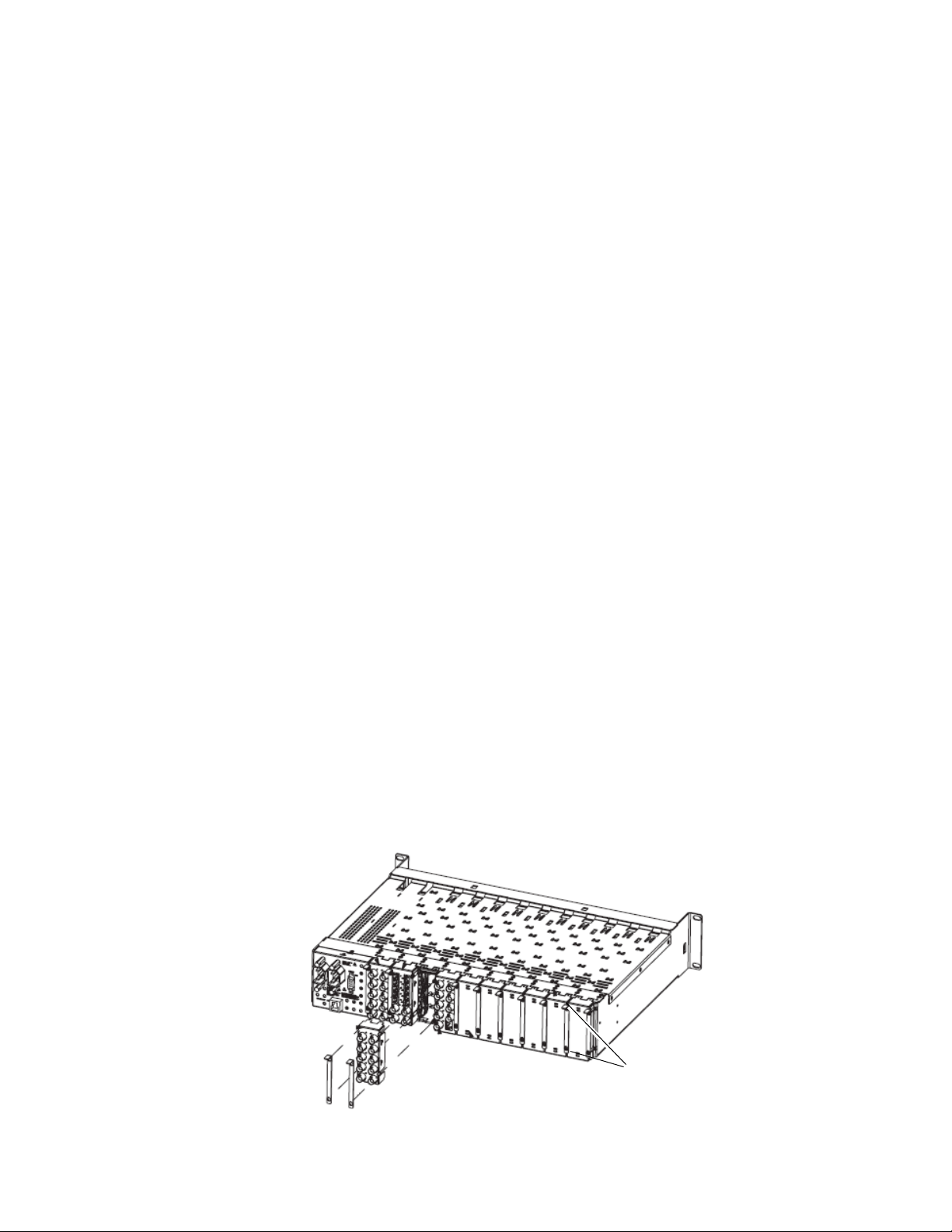
Gecko 8900 Frame
Installation of the 8960ENC module in a Gecko 8900 frame is a process of:
1. Placing the module in the proper frame slot, and
2. Cabling and terminating signal ports.
The 8960ENC module can be plugged in and removed from any Gecko
8900 frame with power on. When power is applied to the module, LED
indicators reflect the initialization process (see Power Up on page 16).
Frame Capacity
The 8960ENC module can be installed in all 8900 Series video frames but
with varying maximum quantities determined by frame cooling capacity.
Ta bl e 1 provides the power capacity, cooling capacity, and maximum
8960ENC module count for each frame type.
Table 1. Power, Cooling, and Module Capacity of 8900 Frames
Power (W)
Recommended Module Cooling (W)
8960ENC Modules
8960ENC Modules with 8900FSS
Capacity Calculated
8900TX
Frame
100 100 100
30 90 90
8900TF-V
Frame
51010
X1010
8900TFN-V
Frame
Installation
Note Module capacity figures assume no other modules are in the frame.
X = Not recommended without forced air cooling.
If you are using an 8900NET module running software version 4.0.0 or
later, you may link to the 8900 Frame Status web page (Figure 10 on
page 28) then select the link to the Power Supply/Demand web page for
determining the power capacity for the frame. Using this function, the
8900NET module will determine how much power is being consumed and
report back when power has been exceeded.
Module Placement in the 8900 Frame
There are ten slot locations in the frame to accommodate either analog or
digital modules. These are the left ten locations. Refer to
page 12.
The two slots on the right are allocated for the power supplies. For additional information concerning the Power Supply module, refer to the Gecko
8900 Frames Instruction Manual.
Figure 2 on
8960ENC—Instruction Manual 11
Page 12
Installation
Frame Monitor or
8900NET Network
Interface Module
Any 8900 Module
Power
Supplies
(only)
0642_04r1
0642-03
J1 J2
J3 J4
J5 J6
J7 J8
J9 J10
IN
DA1
J2
J4
J6
J8
J1 J2
J3 J4
J5 J6
J7 J8
J9 J10
IN
DA3
J1 J2
J3 J4
J5 J6
J7 J8
J9 J10
IN
DA5
J1 J2
J3 J4
J5 J6
J7 J8
J9 J10
IN
DA2
J1 J2
J3 J4
J5 J6
J7 J8
J9 J10
IN
DA7
J1 J2
J3 J4
J5 J6
J7 J8
J9 J10
IN
DA9
J1 J2
J3 J4
J5 J6
J7 J8
J9 J10
IN
DA4
J2
J4
J6
J8
J1 J2
J3 J4
J5 J6
J7 J8
J9 J10
IN
DA6
J2
J4
J6
J8
J1 J2
J3 J4
J5 J6
J7 J8
J9 J10
IN
DA8
J2
J4
J6
J8
J1 J2
J3 J4
J5 J6
J7 J8
J9 J10
IN
DA10
O
U
T
O
U
T
O
U
T
O
U
T
O
U
T
O
U
T
O
U
T
O
U
T
O
U
T
O
U
T
The third slot from the right is allocated for the controller module—either
a Frame Monitor Module or a 8900NET Network Interface Module. For
additional information concerning the controller module options, refer to
the 8900NET Network Interface Module Instruction Manual.
Figure 2. Gecko 8900 Series Frame
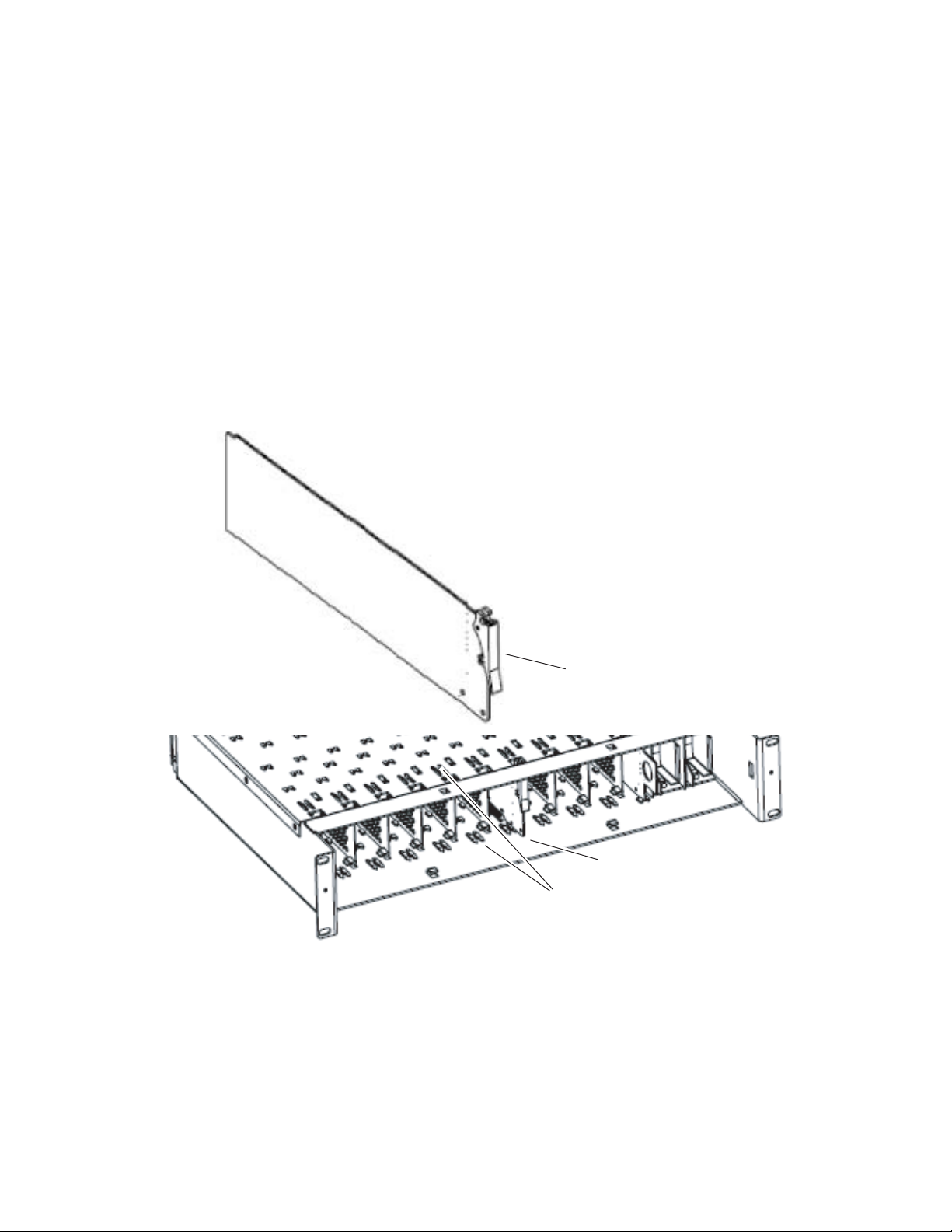
8900 module slots are interchangeable within the frame. There are 10 BNC
connectors in each slot’s I/O group. The functional assignment of each con
nector in a group is determined by the module that is placed in that slot.
The maximum number of modules an 8900 frame can accept is ten.
Figure 3
illustrates the rear connector plate for an 8900 Series frame.
Figure 3. Gecko 8900 Series Frame Rear Connector
To install a module in the frame:
1. Insert the module, connector end first, with the component side of the
module facing to the right and the ejector tab to the top.
-
2. Verify that the module connector seats properly against the backplane.
12 8960ENC—Instruction Manual
3. Press in the ejector tab to seat the module.
Page 13
GeckoFlex Frame
Use needlenose pliers
to pull out blank after
removing retainers.
Installation of the 8960ENC module in a GeckoFlex frame is a process of:
1. Installing the 8900V-R rear module into the rear of the frame,
2. Placing the 8960ENC module in the corresponding front frame slot, and
3. Cabling and terminating signal ports.
Rear Module Installation
To install a rear module into the frame, follow these steps:
1. Each 8900V-R rear module or blank rear adapter cover is held in place
CAUTION Be careful to leave the screws in place as they can be easily lost or fall into
Installation
by two retainer strips as shown in Figure 4. Loosen (but do not remove
completely) the two screws holding each retainer strip to the frame
with a 2 mm (5/64”) hex screwdriver. Pull up on the retainer to remove
it, leaving the screws in place.
equipment below the frame creating a shorting hazard.
2. Remove the blank rear adapter cover by inserting needlenose pliers
into the slots in the top and bottom of the blank and pulling it off.
Note To remove a rear module already installed, follow the same steps. It is helpful
to first remove the front module so the rear can be pulled out more easily.
3. Insert the rear module into the empty slot.
4. Replace each retainer strip over the two screws on both sides of the
module and push down to seat the retainer.
5. Tighten the screws for each retainer just until they are snug. Do not
force or torque the screws too tightly.
Figure 4. Installing Rear Module
8960ENC—Instruction Manual 13
Page 14
Installation
Slide top and bottom card carriers on module
over top and bottom guides on right of slot.
Module installed
Locking Pin
Front Module Side View
0642_10r0
Front Module Installation
After installing the rear module, install the front module as follows:
1. Remove the front cover of the frame if required.
2. Locate the corresponding front slot.
3. Insert the front module so that the plastic card guides on the module
top and bottom edges go over the upper and lower raised rail guides on
the right of the top and bottom of the slot(Figure 5).
4. Carefully slide the module into the rear connector.
5. Lock the front module ejector tab into the locking pin.
Figure 5. Front Module Installation
14 8960ENC—Instruction Manual
Page 15
Cabling
J2
J4
J6
J8
J1
J9 J10
IN
Four NTSC/PAL
Outputs J1 - J4
X
O
U
T
J3
J5
J7
J2
J4
J6
J8
0642_02r1
SDI Loop-through
Input
625 Reference
Input
525 Reference
Input
Reclocked SDI OutputReclocked SDI Output
Loop-through Input
Outputs
Reference Inputs
Installation
Cable the module as described below for either frame type.
Connect an input source to one of the loop-through input connectors, J9 or
J10 (see
Figure 6). The 8960ENC input will accept serial digital video con-
forming to SMPTE 259M 10-bit, 4:2:2 component digital standard. Terminate the unused connector into 75 Ω if the signal is not looped to other
equipment.
The 8960ENC has four analog NTSC/PAL outputs—J1 through J4. Connectors J-5 and J-6 are reclocked SDI outputs.
Separate input BNCs are provided for either 625-line (J7) or 525-line (J8)
black burst reference signals. The reference inputs are 75 ohm or high
impedance (jumper selectable, see
Local Onboard Module Configuration on
page 22).
Figure 6. 8960 Input/Output Connectors
8960ENC—Instruction Manual 15
Page 16
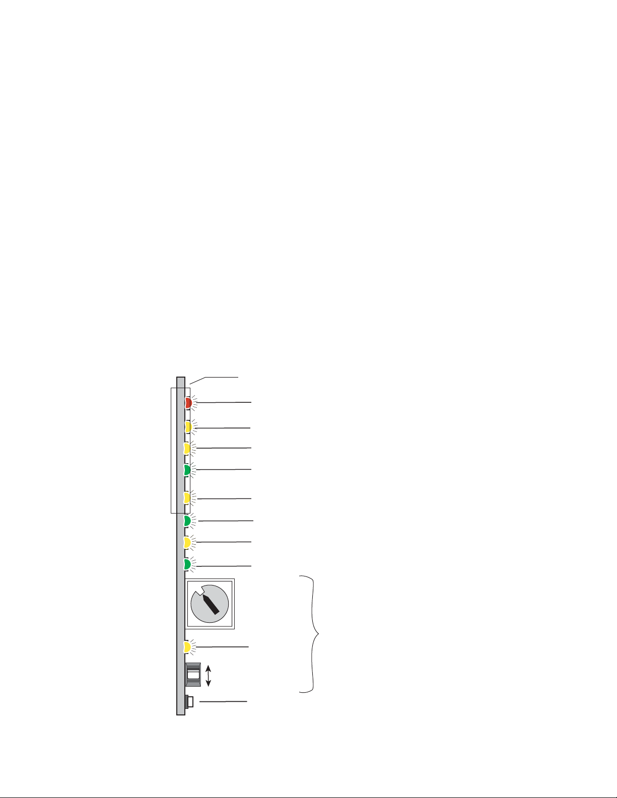
Power Up
0642_06r1
0
1
2
3
4
5
6
7
8
9
A
B
C
D
16-position
Rotary switch
Momentary toggle switch
525 – Green LED on indicates 525-line input is present
PWR – Green LED on indicates power OK
FAULT – Red LED is off during normal operation
Ejector Tab
COMM – Yellow LED indicates communication activity
CONF – Yellow LED indicates configuration activity
Auto/Manual MODE – Yellow LED on indicates automatic input detection mode
625 – Green LED on indicates 625-line input is present
Filter – Yellow LED on indicates signal is being cross-color filtered
Module Configuration Switches and LED
GND
2nd Function
(yellow)
Power Up
Operation Indicator LEDs
The front LED indicators and configuration switches are illustrated in
Figure 7. Upon power-up, the green PWR LED should light and the yellow
CONF LED should illuminate for the duration of module initialization.
Note When a media module is first plugged into a Gecko or GeckoFlex frame, the
8900NET module (if present) may report a momentary fault. This will clear
once the media module has booted up.
With factory default configuration and a valid input signal connected, the
green PWR LED, the yellow AUTO, and one of the green signal standard
LEDs (525 or 625) should illuminate (refer to
Ta bl e 2 on page 17 to see the
possible operating indicator combinations).
Video input presence is indicated by the 525 or 625 LED (indicating a
525-line or 625-line input signal has been detected). The AUTO LED indicates that automatic standard selection is enabled.
Figure 7. LEDs and Configuration Switches
16 8960ENC—Instruction Manual
Page 17
Power Up
A red FAULT LED indicates an error situation and, with the previously
described LEDs, can indicate the operational conditions presented in
Tab le 2 . The table describes LED indications and the signal input/output
conditions and user settings that are indicated.
Table 2. Input Conditions and Resulting Output signals and Indicators
Fault
(red)
OFF ON OFF
OFF OFF ON
Flashing OFF OFF
Flashing ON OFF
Flashing OFF ON
Flashing OFF Flashing
Flashing Flashing OFF
Flashing Flashing OFF
Flashing OFF Flashing
525
(green)
625
(green)
Mode
Input Condition Output Signal
Normal operation; SDI input signal and 525 reference standard selected.
Normal operation; SDI input signal and 625 reference standard selected.
Missing or invalid SDI input signal. No signal.
EDH or format error in the input signal. Output signal has errors.
EDH or format error in the input signal. Output signal has errors.
SDI 625 signal present; selected 625 reference missing or
invalid.
SDI 525 signal present; selected 525 reference missing or
invalid.
525 configued with Manual control, wrong input signal. Corrupted output signal.
625 configured with Manual contol, wrong input signal. Corrupted output signal.
Correct encoded signal with correct color-framing.
Correct encoded signal with correct color-framing.
Correct encoded output; color framing and delay adjustment
from frame sync submodule is free running.
Correct encoded output; color framing and delay adjustment
from frame sync submodule is free running.
Tab le 3 describes the outputs that will be seen for the operating modes and
input conditions listed.
Table 3. Operating Mode, Input Conditions and Resulting Outputs
Standard
Selection
AUTO
Manual 525-line
Manual 625-line
Frame Sync Submodule Present — Module In Sync Mode
Video Input Reference Input Output
Video present Valid reference present Correct output signal with correct timing
No video signal present Valid reference present Corrupted output signal
Or last field if autofreeze is on
Video present Reference not present Correct output signal with free run timing
Video present Invalid reference input Corrupted output signal
Video present Valid reference present Correct output signal with correct timing
No signal present Valid reference present Corrupted output signal
Or last field if autofreeze is on
Video present Reference not present Correct output signal with free run timing
Video present Invalid reference input Corrupted output signal
Invalid Video present Valid reference present Corrupted output signal
Invalid Video present Invalid reference input Corrupted output signal
Video present Valid reference present Correct output signal with correct timing
No video signal present Valid reference present Corrupted output signal
Or last field if autofreeze is on
Video present Reference not present Correct output signal with free run timing
Video present Invalid reference input Corrupted output signal
Invalid Video present Valid reference present Corrupted output signal
Invalid Video present Invalid reference input Corrupted output signal
8960ENC—Instruction Manual 17
Page 18
Power Up
Table 3. Operating Mode, Input Conditions and Resulting Outputs - (continued)
Mode
Frame Sync Submodule Present
Standard
Selection
Manual 525-line
Module In Delay Mode
Manual 625-line
Manual 525-line
Manual 625-line
No Frame Sync Submodule
AUTO
AUTO
Video Input Reference Input Output
Video present Not needed Correct output signal w correct timing
No video signal present Not needed Corrupted output signal
Or last field if autofreeze is on
Video present Not needed Correct output signal w correct timing.
No video signal present Not needed Corrupted output signal
Or last field if autofreeze is on
Invalid Video input Not needed Corrupted output signal
Video present Not needed Correct output signal w correct timing
No video signal present Not needed Corrupted output signal
Or last field if autofreeze is on
Invalid Video input Not needed Corrupted output signal
Video present Not needed Correct output signal
No video signal present Not needed No output signal
Video present Not needed Correct output signal
No video signal present Not needed No output signal
Invalid Video input Not needed Corrupted output signal
Video present Not needed Correct output signal
No video signal present Not needed No output signal
Invalid Video input Not needed Corrupted output signal
18 8960ENC—Instruction Manual
Page 19

Configuration
Configuration Summary
Configuration
The 8960ENC can be configured locally using onboard switches or
remotely using the 8900NET network interface GUI or a networked control
panel.
Refer to the following sections for configuration instructions:
• Configuration Summary (page 19)
• Local Onboard Module Configuration (page 22)
• Remote Control and Monitoring (page 26)
Operation of these control types is explained in detail in their respective
sections of this manual.
The configuration of the 8960ENC establishes:
• Reference signal input impedance (jumper selection),
• Local only or Remote/Local control (jumper selection),
• Input/Output standard setup,
• Signal processing adjustment,
• Signal filtering setup, and
• Optional Frame Sync module setup.
Output standard setup provides multi-standard support of analog output
signals such as NTSC, Japanese NTSC, PAL-B, PAL-M.
The factory (default) settings for signal processing functions are set to pass
a calibrated broadcast quality signal at optimum levels. Signal processing
amplifier adjustments are available to correct deficiencies in the input
signal.
Table 4 on page 20 provides a summary in table format of all parameters
and their ranges, default values, and remote, local, and control panel function names and locations for setting each value.
8960ENC—Instruction Manual 19
Page 20

Configuration
Configuration Summary Table
Ta bl e 4 provides a complete summary of the 8960ENC functions and a
comparison of the functionality available with each control type along with
the ranges and default values for each parameter.
Table 4. Summary of Configuration Functions
Function
Type
Standard Recognition Auto Auto or Manual
Manual Standard
Selection
Output Video Setup Setup Setup or No Setup
Vertical Interval Setup Off On or Off
Line 21 Setup Off On or Off
Line 22 Setup Off On or Off
NTSC or PAL-M
selection
Standards Selection
Controls Type
Output Video Level 97.09%
User Adjustments Calibrate Calibrate or User
Levels Control Type Numeric Numeric2 or Slider
Luma Level adjustment
to set luma gain
Chroma Level adjustment to set chroma gain
Hue Level adjustment
(525 only)
Black Level adjustment 7.54%
Lock Source selection Reference Video or Reference
Default
525 525 or 625
NTSC NTSC or PAL-M
Numeric Numeric
99.74%
99.52%
0 degrees
Range/Choices
Resolution
b
or Slider
41.5 to 171.55%
(0.51% steps)
89.5 to109.9%
(0.08% steps)
88 to 110.95%
(0.09% steps)
0 to 358.05 degrees
(0.35 degree steps)
-14.22 to 21.48%
(0.34% steps)
Web Page/
Function Name
Standard Selection/
Standard Recognition pulldown
Standard Selection/
Manual Selection pulldown
Standard Selection/
Output Video Setup pulldown
Standard Selection/
VI Setup pulldown
Standard Selection/
Line 21 Setup pulldown
Standard Selection/
Line 22 Setup pulldown
a
2
2
2
2
2
Standard Selection/
NTSC/PAL-M Select pulldown
Standard Selection/
Controls Type pulldown
Standard Selection/
Output Video Level (% 1Vpp)
Slider or arrow controls
Levels/
User Adjustments pulldown
Levels/
Controls Type pulldown
Levels/
Luma Level (% White)
Luma Level slider
or arrow controls
Levels/
Chroma Level (% saturation)
Chroma Level slider
or arrow controls
Levels/
Hue (degrees)
Hue Level slider
or arrow controls
Levels/
Black Level (% White)
Black Level slider or arrow
controls
Timing/
Lock Source pulldown
Function Switch
Bank/Setting
1:0 Auto Std
1:1 Lines
1:2 FF Setup
2:F VI Setup
1:D L21Setup
1:E L22Setup
1:3 525 Std
N/A N/A Web page only
1:4 Video
1:5 Levels
N/A N/A Web page only
1:6 Luma
1:8 Chroma
1:9 Hue
1:7 Black
2:0 Lock To
Newton
Control
Panel
Notes/
Conditions
Manual mode
selected in
Standard Recognition above.
525 only
User mode
selected in User
Adjustments
above
20 8960ENC—Instruction Manual
Page 21

Configuration
Table 4. Summary of Configuration Functions
Function
Type
Timing Control Type Numeric Numeric or Slider
Fine Delay control 0 ns
Horizontal Delay 0
Vertical Delay 0
Freeze Recognition Manual Manual or Auto
Freeze Mode Frame Field or Frame
Freeze Field Field 1 Field 1 or Field 2
Freeze Signal Last Field Last Field or Black
Force Manual Freeze Off On or Off
Cross Color Removal Disable Enable or Disable
Chrominance Signal Disable Enable or Disable
Burst Signal Disable Enable or Disable
VI Processing Pass Pass or Delete
Test Mode Disable Enable or Disable
Test Signal Colorbar Colorbar or Linearity
Recall factory defaults N/A See Defaults column
a
Grass Valley no longer supports PAL-M in any of its modular products. Although this setting may work in certain applications, Grass Valley will not warrant that it works
or provide support if problems are encountered using this product with PAL-M signals. This product has not been modified to eliminate support for PAL-M. If this product
has been used with PAL-M in the past without problems, there shouldn’t be any issues using it for the same application. However, it is not recommended that customers
use it in any new PAL-M applications.
b
The numeric displays are approximate values only. Calculation of displayed values are subject to decimal place truncation. Variation from the absolute value increases
at higher adjustment levels.
Default
Range/Choices
Resolution
0 to 40.80 ns
(0.16 ns steps)
0 to 63418 ns (525)
0 to 63862 ns (625)
(37 ns steps)
0 to 524 lines (525)
0 to 624 lines (625)
(1line steps)
Web Page/
Function Name
Timing/
Controls Type pulldown
Timing/
Fine Delay
Fine Delay slider or arrow
controls
Timing/
Horizontal Delay slider or arrow
controls
Timing/
Vertical Delay slider or arrow
controls
Timing/
Freeze Recognition pulldown
Timing/
Freeze Mode pulldown
Timing/
Freeze Field pulldown
Timing/
Freeze Signal pulldown
Timing/
Freeze button
Video Processing/
Cross Color Removal pulldown
Video Processing/
Chrominance Signal pulldown
Video Processing/
Burst Signal pulldown
Video Processing/
VI Processing pulldown
Video Processing/
Test Mode pulldown
Video Processing/
Test Signal Select pulldown
Recall Factory Defaults/
Factory Defaults button
Function Switch
Bank/Setting
N/A N/A Web page only
2:1 Fine Dly
2:2 H Delay
2:3 V Delay
2:4 Frz Rec
2:6 Frz Mode
2:7 FrzField
2:8 Frz Sig
2:5 Freeze
2:A CrossClr
2:A Chr Sig
1:B Burst
1:C VI Proc
2:D Tst Mode
2:C Tst Sel
1:F (down) N/A
Newton
Control
Panel
Notes/
Conditions
No submodule
required
8900FSS
submodule
installed.
Output signal
processing
Replace output
signal with test
pattern
8960ENC—Instruction Manual 21
Page 22

Configuration
GRASS VALLEY GROUP 8960ENC COMPOSITE ENCODER 671-4698-
GND
FUNCTION – rotary switch
SW1 – actuator toggle switch
2nd – second function LED
CONF – configuration LED
JP1
Place jumper in
Local position to
lock out remote
access.
Local
Local &
Remote
JP1
JP10 JP11
Remote Lockout
Reference Input
Impedance
75 Hi Z
JP11 (625)
75 Hi Z
0642_07r1
Local Onboard Module Configuration
The 8960ENC module can be configured locally using the rotary and toggle
switches shown in
Figure 8. Two LEDs (CONF and 2nd) indicate status of
the configuration process. These four components perform the following:
• Function (rotary) switch addresses a desired function for configuration
and provides two sets (banks) of 16 functions (0 through 9,
A through F), although not all positions are used.
• 2nd (second function) LED when on, indicates that the rotary switch is
addressing the second (Bank 2) of functions (see Table 5 on page 24)
that control the optional 8900FSS Frame Sync Submodule.
• SW1 (paddle) switch actuates or selects the desired setting for the
selected function when the switch is held momentarily in either the up
or down position.
• CONF (configuring) LED when on, indicates the module is initializing
or processing configuration information.
Note Function switch position F (Recall) in Bank 1 can be used to return the
module configuration to the factory default.
The following onboard jumpers are used to permit or lockout remote
control and set reference input impedance.
• Remote Control Lockout – When a jumper is placed across pins 1 and 2
of jumper block JP1 (see Figure 8), module output mode settings are
adjustable from the Local on-board switches only. To have both Local
and Remote access, set the jumper across pins 2 and 3.
• Reference Input Impedance – When a jumper is placed across pins 1
and 2 of jumper block JP10 (525 line reference) or JP11 (625 line reference), Reference Input is terminated into 75 Ω (see Figure 8). To have
high impedance termination, set the jumper across pins 2 and 3 of the
appropriate jumper block.
Figure 8. Module Configuration Switches, LEDs, and Jumpers
22 8960ENC—Instruction Manual
Page 23

Onboard Module Configuration
To make configuration settings:
1. Rotate the Function Switch to Bank 1 (2nd LED off) or Bank 2 (2nd LED
on) and to the desired function within that bank.
Note The Function switch should be kept in Bank 2 position E when not in use to
avoid any inadvertent change in configuration. E is an inactive position.
2. Move the paddle switch to the up or down position and hold
momentarily to set the desired function (refer to Table 5 on page 24).
3. Return the Function switch to Bank 2 position E when finished with
entire configuration process.
Adding/Deleting Setup for 525 Format
Bank 1, Position 2
Bank 1, position 2 is an overall setup on/off selection which overwrites all
other setup controls. When
lines in the full-field (FF) picture—which is composed of AP (active pic
ture) and VI (vertical interval)—have 54 mV setup added. The luma
chroma gain is reduced to provide a 1 V peak-to-peak nominal level. When
No Setup (off) is selected, AP and VI have no setup, and luma chroma gain is
increased to provide a 1 V peak-to-peak nominal level.
Setup (on) is selected for NTSC 525 format, all
Configuration
-
When Setup is selected, setup can be selectively removed from lines 21, 22
or the vertical interval. When
any line.
Bank 1, Position D
Bank 1, position D controls setup ON/OFF for line 21 in both fields.
Bank 1, Position E
Bank 1, position E controls setup ON/OFF for line 22 in both fields.
Bank 2, Position F
Bank 2, position F controls setup ON/OFF VI lines only both fields.
When Factory Default is selected setup is on AP lines, no setup on VI lines, no
setup on line 21, setup on line 22.
No Setup is selected, setup cannot be added to
8960ENC—Instruction Manual 23
Page 24

Configuration
Table 5. Encoder Configuration Functions
Function
Switch
Input/Output Signal Adjustments
0 Auto Manual
1525 625
2On Off
3NTSCPAL-M
4 Increase Decrease
Signal Processing Adjustments
5 Enable Calibrated
6 Increase Decrease
7 Increase Decrease
8 Increase Decrease
Bank 1 - 2nd LED Off
9 Increase Decrease
Signal Filtering Setup
A Enable Disable
B Enable Disable
C Pass Delete
DOn Off
EOn Off
F – Recall
Paddle
Switch Up
Paddle
Switch Down
Function Description
Standard Recognition – Automatic standard recognition or manual
select enable.
Manual Standard – Selection of 525-line or 625-line signal. The
internal automatic standard detection is disabled when Manual is
selected.
Setup in the output video (this function is disabled if the standard is
625). Select On for NTSC, select Off for Japanese NTSC.
525 NTSC/PAL-M Selection – Defines the subcarrier frequency of
a
the output video signal (Function is Disabled if standard is 625).
Output Video Level – controls ± 6 dB gain adjustment of the output
video signal in 256 steps.
User Adjustments – Enables processing amplifier functions (6-9) or
selects Calibrated presets optimized for a calibrated video output.
Luma Level b – Can be adjusted ±10% in 256 incremental steps.
Black Level 2 – Can be adjusted ±100 mV in 256 incremental steps.
Chroma Level 2 – Can be adjusted ±10% in 256 incremental steps.
Hue 2 – Chroma phase can be rotated from 0 to 360 degrees. Disabled if standard is PAL.
Enable/Disable modulated chroma signal
Enable/Disable burst reference in the output signal
VI Processing Options – Select Pass for picture content processed
and passed through, or Delete to remove picture content.
Adds or removes setup for line 21 in both fields
Adds or removes setup for line 22 in both fields
Factory Default – Resets all user adjustable parameters to optimized
setting for a calibrated SDI input signal.
24 8960ENC—Instruction Manual
Page 25

Configuration
Table 5. Encoder Configuration Functions - (continued)
Function
Switch
0 Video Reference
1 Increase Decrease
2 Increase Decrease
3 Increase Decrease
4Manual Auto
5 Off On
6Frame Field
7 Field 1 Field 2
8 Last Field Black
Bank 2 - 2nd LED On
9
A Enable Disable
B
C Colorbar Linearity
D Enable Disable
E
FOn Off
a
Grass Valley no longer supports PAL-M in any of its modular products. Although this setting may work in certain applications,
Grass Valley will not warrant that it works or provide support if problems are encountered using this product with PAL-M signals.
This product has not been modified to eliminate support for PAL-M. If this product has been used with PAL-M in the past without
problems, there shouldn’t be any issues using it for the same application. However, it is not recommended that customers use it in
any new PAL-M applications.
b
Inactive if User Adjustments (switch position 5) is set to Calibrated.
c
Inactive if Frame Sync Submodule is not present.
Paddle
Switch Up
currently not used
currently not used
Inactive Position
Paddle
Switch Down
Function Description
Lock Source – Selecting Video forces delay mode even if a reference
signal is present
Fine delay adjustment
Horizontal Delay c – Provides synchronizer delay adjustment in clock
increments and line increments accordingly.t
Vertical Delay 3 – Provides synchronizer delay adjustment in clock
increments and line increments accordingly
Freeze Recognition 3 – Selecting Auto stores the last field in the
frame synchronizer to use if the input video is lost or corrupted.
Freeze Manual 3 – Enables/Disables manual selection of Freeze
Mode according to positions 6&7.
Freeze Mode 3 – Select between Frame and Field.
Freeze Field 3 – Select between Field 1 and Field 2.
Freeze Signal 3 – Selects the freeze output signal if Auto or manual
freeze is activated.
Cross color removal – Enables/Disables the cross-color removing
2D filter.
Test Signal – Select between colorbar and linearity signal.
Test Mode – If Test is selected, the input SDI is replaced with the test
pattern selected in 2:C.
Adds or removes setup for vertical interval in both fields
8960ENC—Instruction Manual 25
Page 26

Configuration
Remote Configuration and Monitoring
8960ENC configuration and monitoring can be performed using a web
browser GUI interface or a networked Newton Control Panel when the
8900NET Network Interface module is present in the video frame (Gecko
8900TFN-V frame). Each of these interfaces is described below.
Note For remote access, make sure the jumper block on the module is set for both
Local and Remote access (Figure 8 on page 22).
8900NET Module Information
Refer to the 8900NET Network Interface Module Instruction Manual for
information on the 8900NET Network Interface module and setting up and
operating the Gecko 8900 frame network.
Note The 8900NET module in the frame must be running software version 3.2.2 or
higher for proper remote and control panel operation. Upgrade software and
instructions for the 8900NET can be downloaded from the Grass Valley web
site.
Newton Control Panel Configuration
A Newton Control Panel (hard or soft version) can be interfaced to the
Gecko 8900 Series frame over the local network. Refer to the documentation
that accompanies the Newton Modular Control System for installation,
configuration, and operation information.
Control panel access offers the following considerations for module configuration and monitoring:
• Ability to separate system level tasks from operation ones, minimizing
the potential for on-air mistakes.
• Ability to group modular products—regardless of their physical locations—into logical groups (channels) that you can easily manipulate
with user-configured knobs.
• Update software for applicable modules and assign frame and panel IP
addresses with the NetConfig Networking application.
• Recommended for real-time control of module configuration parameters, providing the fastest response time.
Note Not all module functions are available with the control panel, such as factory
default recalls. The available Newton control panel controls for the 8960ENC
module are listed in Table 4 on page 20.
An example of the Newton Configurator is shown in Figure 9 on page 27.
26 8960ENC—Instruction Manual
Page 27

Figure 9. Newton Configurator Example
Configuration
Web Browser Interface
The web browser interface provides a graphical representation of module
configuration and monitoring.
Use of the web interface offers the following considerations:
• Provides complete access to all module status and configuration func-
tions, including naming of inputs and outputs, factory parameter and
name default recalls, E-MEM functions, slot configuration, and SNMP
monitoring controls.
• Web access will require some normal network time delays for pro-
cessing of information.
• Configuration parameter changes may require pressing
Enter, upload processing time, and a manual screen refresh to become
effective.
• Web interface recommended for setting up module signal and slot
names, E-MEMS, and reporting status for SNMP and monitoring.
Refer to the Frame Status page shown in Figure 10 on page 28. The 8900
modules can be addressed by clicking either on a specific module icon in
the frame status web page or on a module name or slot number in the link
list on the left.
Apply button or
8960ENC—Instruction Manual 27
Page 28
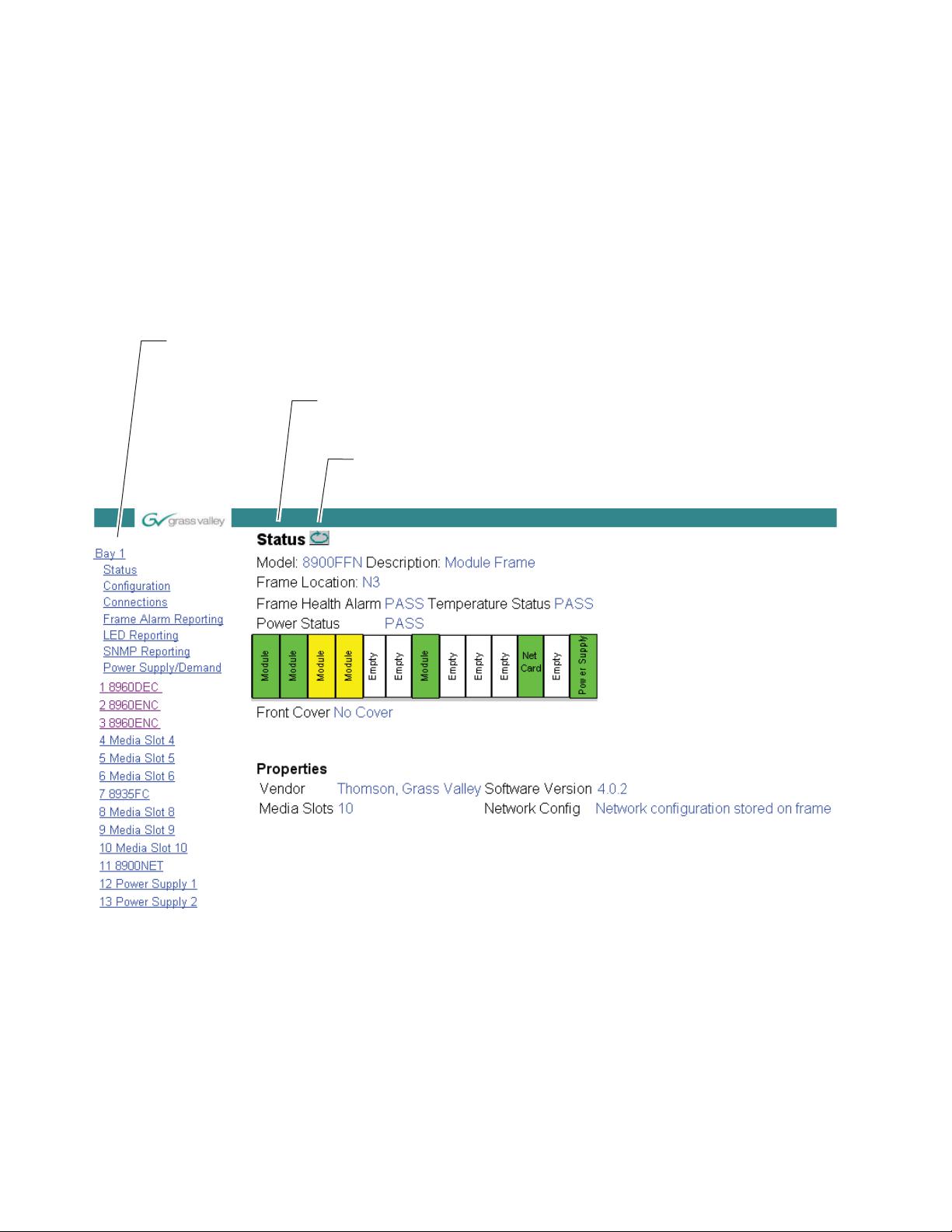
Configuration
0612-12r2
The Links section lists the frame and its current modules. The selected link's Status
page is first displayed and the sub-list of links for the selection is opened. The sub-list
allows you to select a particular information page for the selected device.
Content display section displays the information page
for the selected frame or module (frame slot icons are also
active links).
Refresh button for manual
refresh of page
Note The physical appearance of the graphics on the web pages shown in this
manual represent the use of a particular platform, browser and version of
8900NET module software. They are provided for reference only. Web pages
will differ depending on the type of platform and browser you a
the version of the 8900NET software installed in your system. This manual
reflects 8900NET software version 4.0.2.
re using and
For information on status and fault monitoring and reporting shown on the
Status page, refer to Status Monitoring on page 51.
Figure 10. Gecko 8900 Frame Status Page
28 8960ENC—Instruction Manual
Page 29

8960ENC Links and Web Pages
The 8900 web interface GUI provides the following links and web pages for
the 8960ENC module (
• Status – reports input and reference signal status and module informa-
tion (page 30),
• Standard Selection – provides controls for setting module line standard
and setting output video levels (page 31),
• Levels – provides access to controls for adjusting luma, chroma, hue,
and black levels (page 34),
• Timing – provides lock source and fine phase adjustments and hori-
zontal and vertical timing adjustments when the 8900FSS is installed
(page 37),
• Video Processing – provides controls for enabling and disabling video
functions on the encoded output (page 40),
• Recall Factory Defaults – use this web page to recall factory defaults for
the module (page 41), and
Figure 11):
Configuration
• Slot Config – provides a Locate Module function, Slot Identification
fields, Slot Memory controls, and links to the Frame Alarm and SNMP
Trap enables on the 8900NET module web pages (page 42).
Figure 11. 8960ENC Web Page Links
On all web pages, click on Apply to activate settings in each selection then
refresh the web page at the top of the page with the
shown at left).
Refer to Table 4 on page 20 for a complete summary of controls, defaults,
and parameter ranges.
Refresh button (both
8960ENC—Instruction Manual 29
Page 30

Configuration
Use
this
link
Status Web Page
The Status web page (Figure 12) shows the input signal status of the component analog video input. Color coding of the display indicated the signal
status. Refer to
coding.
Information about the module, such as part number, serial number, hardware revision and software and firmware versions are given in a read-only
section at the bottom of the display.
Figure 12. 8960ENC Status Web Page
Status Monitoring on page 51 for an explanation of the color
30 8960ENC—Instruction Manual
Page 31

Standard Selection Web Page
Use
this
link
The Standard Selections web page provides controls to set the line standard, enable setup on the vertical interval and the output video, and set the
video output level from the module.
Set the following parameters on this web page:
Configuration
• Set the Standard Recognition control to either
allows the module to detect and accept either a 525-line or 625-line
input signal. The line standard value will be reported as a read-only
value in the menu when
Figure 13. Standard Selection Web Page
Auto is selected (see Figure 13).
Auto or Manual. Auto mode
8960ENC—Instruction Manual 31
Page 32

Configuration
Manual Mode
The Manual setting forces the module to operate in the mode chosen by
the user. If
allow selection of either
Figure 14. Standard Selection Web Page – Manual Mode
Manual is selected, the Line Standard control will appear and
525 or 625 (Figure 14).
• The Output Video Setup control appears only when a 525-line standard
is enabled, either manually or automatically. For output video with
54 mV of setup, select
Setup. Select No Setup for Japanese NTSC or other
requirements with no setup.
When Setup (on) is selected for NTSC 525 format, all lines in the
full-field (FF) picture—which is composed of AP (active picture) and VI
(vertical interval)—have 54 mV setup added. The luma chroma gain is
reduced to provide a 1 V peak-to-peak nominal level. When
No Setup
(off) is selected, AP and VI have no setup, and luma chroma gain is
increased to provide a 1 V peak-to-peak nominal level.
When Setup is selected, setup can be selectively removed from lines 21,
22 or the vertical interval. When
No Setup is selected, setup cannot be
added to any line. Factory default provides setup on AP lines, no setup
on VI lines, no setup on line 21, and setup on line 22.
• Select NTSC or PAL-M subcarrier format.
Note Grass Valley no longer supports PAL-M in any of its modular products.
Although this setting may work in certain applications, Grass Valley will not
warrant that it works or provide support if problems are encountered using
this product with PAL-M sig
inate support for PAL-M. If this product has been used with PAL-M in the past
without problems, there shouldn’t be any issues using it for the same application. However, it is not recommended that customers use it in any new
PAL-M applications.
nals. This product has not been modified to elim-
32 8960ENC—Instruction Manual
Page 33

Configuration
• Adjust the Output Video Level using either the Slider or Numeric adjust-
ment mode (see Figure 13 on page 31 for numeric control and Figure 15
for slider control).
The gain of the output video is adjusted relative to a calibrated value of
1
V p-p (100%). For example, if you have an output of 1V p-p, the value
would be set to 100%.
In either adjustment mode, the single arrow will increment the value by
approximately 0.5% per click. The double arrows increment or decre
ment the value by approximately 10x (5% per click).
Note Numeric displays are for approximate values only. Calculation of displayed
values are subject to decimal place truncation. Variation from the absolute
value increases at higher adjustment levels.
Figure 15. Output Level Adjustments – Slider Control Type
-
8960ENC—Instruction Manual 33
Page 34

Configuration
Use
this
link
Levels Web Page
The Levels web page provides access to processing amplifier controls. You
may select user adjustable to set the values or set the module to factory calibrated levels.
Set the User Adjustments pulldown to either Calibrate or User.
In
Calibrate mode, the module selects preset factory default values opti-
mized for a calibrated video output. The values will be reported as
read-only as shown in Figure 16.
Figure 16. Levels Web Page – Calibrate Mode
In User mode, select Slider or Numeric adjustment mode to adjust the following output video parameters (see Figure 17 on page 35 for numeric controls and Figure 18 on page 36 for slider controls):
• Luma level (luminance gain relative % white),
• Chroma level (chrominance gain relative % saturation),
• Hue, 0 – 360 degrees (525 standard only), and
• Black level (black level relative to % white).
In either adjustment mode, the single arrow will increment/decrement the
values by approximately 1x the parameter value. The double arrows will
increment/decrement the values by approximately 10x. In
ment mode, you may also enter a value directly into the window.
Numeric adjust-
34 8960ENC—Instruction Manual
Page 35
Configuration
Note Numeric displays are for approximate values only. Calculation of displayed
values are subject to decimal place truncation. Variation from the absolute
value increases at higher adjustment levels.
Figure 17. Levels Web Page – User Mode – Numeric Control Type
8960ENC—Instruction Manual 35
Page 36

Configuration
Figure 18. Levels Web Page – Slider Control Type
36 8960ENC—Instruction Manual
Page 37

Timing Web Page
Use
this
link
The Timing web page shown in Figure 19 on page 38 (Numeric control
mode) or Figure 20 on page 39 (Slider control mode) provides lock source
selection and fine phase adjustments for the output video. When the
optional Frame Sync submodule is installed, additional horizontal and ver
tical phase adjustments and freeze options become available.
Select the Apply button to activate each selection.
Configuration
-
Adjustment parameters may be selected in
Slider or Numeric mode. Select the
desired mode in the Controls Type window. In either mode, the single
arrow will increment/decrement the values by approximately 1x the value
of the parameter. The double arrows will increment/decrement the values
by approximately 10x. In
Numeric adjustment mode, you may also enter a
value directly into the window.
Set the following parameters in this web page:
• Choose a Lock Source from
• Adjust the
Fine Delay in nanoseconds with either Slider or Numeric
Reference input or Video input.
adjustment mode.
If the optional 8900FSS Frame Sync submodule is installed (Submodule
Option: Present as shown in Figure 19 on page 38), you can also make the
following delay adjustments and set freeze operation parameters:
• Adjust Horizontal Delay in nanosecond increments and Vertical Delay
phase adjustment in line increments in either
• Set Freeze Recognition to
Manual or Auto. Selecting Auto stores the last
Slider or Numeric mode.
field in the Frame Synchronizer to use if the input video is lost or corrupted.
• Set the Freeze Mode to
Frame or Field.
• Set the Freeze Field to
• Set the Freeze Signal to
output signal when a freeze is activated in either
• To perform a manual freeze, click the
Field 1 or Field 2.
Last Field or Black. This will determine the freeze
Auto or Manual mode.
Freeze button at the lower left of
the web page.
8960ENC—Instruction Manual 37
Page 38

Configuration
Figure 19. Timing Web Page – Numeric Control Type
38 8960ENC—Instruction Manual
Page 39
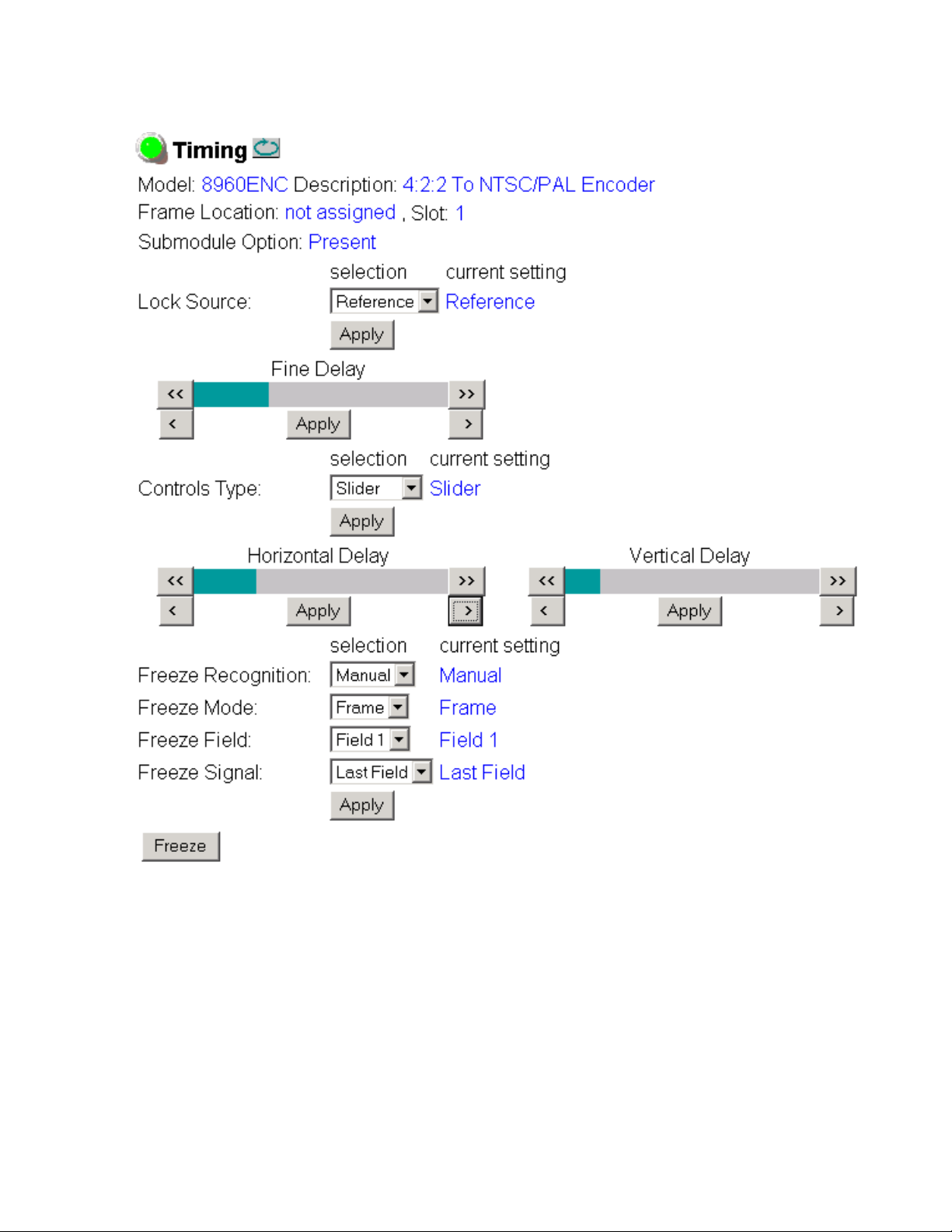
Figure 20. Timing Web Page – Slider Control Type
Configuration
8960ENC—Instruction Manual 39
Page 40

Configuration
Use
this
link
Video Processing Web Page
Use the Video Processing web page shown in Figure 21 to enable or disable
the:
• Cross-color removing 2D filter,
• Modulated chrominance signal,
• Burst reference in the output signal, and
• Test Mode signal output.
In the VI Processing pulldown select
selected, the picture content in the vertical interval is processed and passed
through. If
tical interval.
Test Mode is enabled, choose Colorbar or Linearity as the test output signal.
If
Figure 21. Video Processing Web Page
Delete is selected, the picture content is removed from the ver-
Pass or Delete VI signal. When Pass is
40 8960ENC—Instruction Manual
Page 41
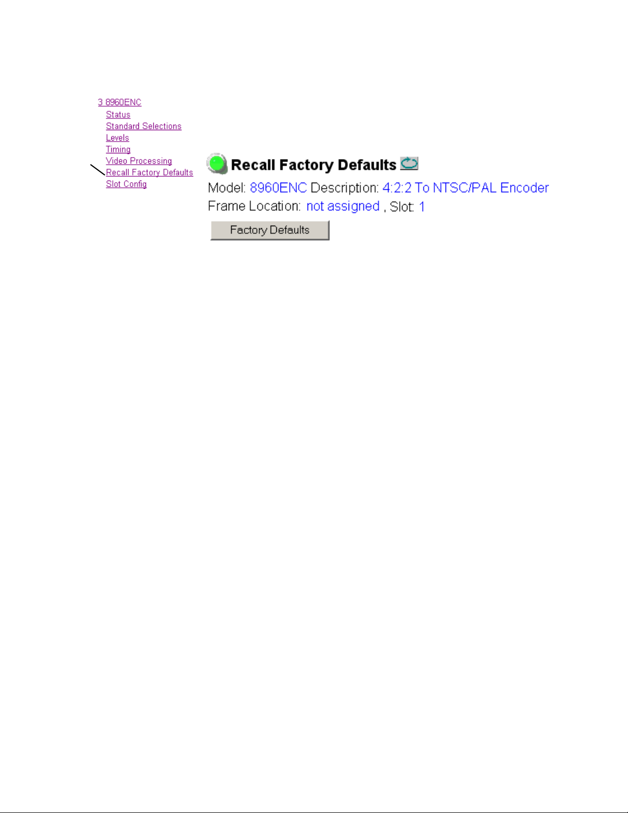
Recall Factory Defaults Web Page
Use
this
link
Factory default settings can be recalled by selecting the Factory Defaults
button shown in Figure 22 on the Recall Factory Defaults web page.
Figure 22. Factory Default Recall Web Page
Configuration
8960ENC—Instruction Manual 41
Page 42

Configuration
Use
this
link
Slot Config Web Page
Use the Slot Config web page (Figure 23 on page 43) to perform the following functions on the 8960ENC module:
• Locate Module – selecting the Flash radio button flashes the yellow
COMM and CONF LEDs on the front of the module so it can be located
in the frame.
Slot Identification – you may identify the module by typing a specific
•
name in the
module and travels with the 8900NET module if it is moved to another
frame. Select
An Input Signal Name field is also provided for entering a name for the
input signal. Press the
name.
• Slot Memory – the slot configuration for each media module is automatically saved periodically (once an hour) to the 8900NET module in that
frame. You may also select the
save the current configuration for this slot. The configuration is saved
on the 8900NET module. If the 8900NET module is removed or
powered down, the stored configurations are not saved.
Name field. The assigned name is stored on the 8900NET
Default to enter the factory default module name.
Default button to return to the factory default
Learn Module Config button at any time to
When the Restore upon Install box has been checked, the current configuration saved to this slot is saved as slot memory. When the current
module is removed and another module of the same type is installed,
the configuration saved to the 8900NET module will be downloaded to
the new module. The box must be checked before the current module
with the saved configuration is removed.
• Frame Health Reports Link – select the Frame Health Reports link to open
the 8900NET module Frame Alarm Reporting web page. This web page
allows configuration of the alarms and warnings that are reported to
the external Frame Health Alarm connector on the rear of the GeckoFlex frame.
LED Reports – This link appears when the 8900NET module has software
•
version 4.0.2 or later installed. When the link is selected, a read-only
status report of the 8900NET Hardware Switch state is given. In the
LED Reporting section of the web page, LED Reporting on the 8900NET
module can be enabled or disabled as desired.
SNMP Trap Reports Link – select the SNMP Trap Reports link to open the
•
8900NET SNMP Reporting web page. This link will only be present
when SNMP Agent software has been installed on the 8900NET
module. This web page allows configuration of which alarms and
warnings that are reported to the SNMP management software.
Refer to the 8900NET Instruction Manual for complete details on using the
8900NET web pages.
42 8960ENC—Instruction Manual
Page 43

Figure 23. 8960ENC Slot Config Web Page
Configuration
8960ENC—Instruction Manual 43
Page 44

Software Updating
Software Updating
Software updating for the module is done using the 8900-FLOAD-CBL
assembly available from Grass Valley Customer Service.
The 8900-FLOAD-CBL assembly consists of a circuit board and serial and
ribbon cables that connect between a serial port on a PC and the ISP con
nector on an 8900 or 2000 module. The software upgrade requires downloading files from a PC to the module through the cable assembly.
Equipment Required
The following items are required for this procedure:
• 8900-FLOAD-CBL assembly (circuit board and 2 cables),
• Software CD containing ModLoad.exe application (comes with the
• PC with unused Serial Com port that can be connected serially to the
-
8900-FLOAD-CBL kit) and 8900/2000 module software files and
Release Notes, and
8900 or 2000 frame.
Acquiring Software Updates
For information on acquiring the upgrade kit and available software
updates, contact Grass Valley Customer Service at the location given in
Contacting Grass Valley on page 4 at the front of this manual.
44 8960ENC—Instruction Manual
Page 45
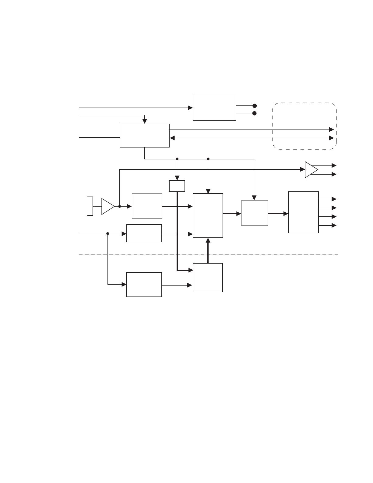
Functional Description
+12V
Module Slot ID
Fault Reporting
Local User
Interface
Intra-frame Control Interface
4:2:2
SDI
Input
10
10
10
4X NTSC/PAL
2X SDI
Optional Submodule *
Available with Frame
Communication Upgrade
* The main encoder module automatically recognizes the attachment of the frame synchronizer submodule.
NTSC/PAL
Reference
-5V
+5V
Microcontroller
On-board
Switching Mode
Power Supply
module
Serial to
Parallel
Converter
EDH
Frame Delay/
Synchronizer
H Genlock to
External Video
Color Frame
ID Generation
Output
Filter and
Driver
Cross-color
Remover
&
Genlock
with
FIFO
10-bit
Composite
Encoder
0642-01
RC
Refer to the block diagram in Figure 24 while reading the following functional description.
Figure 24. 8960ENC Block Diagram
Functional Description
Serial 4:2:2 Input Stage & Output
The SDI signal is connected to the high impedance loop-through input. The
input amplifier auto-equalizes the signal up to 24 dB loss (300 meters of
Belden 8281 cable). The reclocked signal is available on two SDI output con
nectors and also on an internal 10-bit parallel bus for further processing.
Error Detection Handling (EDH) is tested by the microcontroller which
flashes the Fault LED when errors are detected.
-
8960ENC—Instruction Manual 45
Page 46

Functional Description
Cross-Color Remover
Synchronizer
The encoder accepts 525/625 component video and before the composite
encoding, removes luminance components that could cause discoloration
in high detail diagonal content areas. By doing this at the decoder side,
there are no artifacts when using digital comb filtering based decoders such
as the 8960DEC Adaptive Decoder. The pre-filtering is done in a Field Pro
grammable Gate Array (FPGA) using a spatio-temporal comb filter that
gives full vertical resolution while removing all unwanted cross-color
details. All the necessary timing and interfacing signals are generated inter
nally and adjusted automatically to the incoming signal’s standard.
Phasing range is infinite with the addition of the optional frame synchronizer module. The frame synchronizer is locked to the selected reference in
the horizontal and vertical domain in 37 ns steps.
-
-
10-bit Encoder and Output Driver
The 10-bit precision encoder can be switched through auto/manual standard selection to multi-standard outputs:
•NTSC
•PAL-B
•PAL-M
Fine phase adjustment is available within a 0-45 ns range.
The oversampling restoration filter gives an exceptionally flat response and
a linear phase signal that is amplified and automatically DC-restored
before it is output to the four BNC connectors.
Color-frame Lock
When the Lock Source is set to Reference (factory default configuration),
the composite output video is automatically color-frame locked when a
blackburst reference signal is present. The composite analog video output
signal and the reference have to be frequency-locked and the phase differ
ence has to be within ±10 video lines for color-frame locking.
-
If during module configuration Lock Source is set to Video, color-frame
lock is free-running. If the output signal is PAL-M encoded, the board locks
to NTSC reference signal.
46 8960ENC—Instruction Manual
Page 47

Microcontroller
At power up, the microcontroller configures the encoder chip and loads the
firmware according to the last stored user settings. The user adjustable
parameters are input through a multifunction rotary and toggle switch
combination interface with a preset option of the factory recall settings. All
the functions are remote read/writable through the intraframe control
interface (available in 8900TX/TF/TFN frames). The Fault Reporting
output is pulsed in case of loss of input signal.
Regulator
The input +12 V is stepped down to +5 V and -5 V using an on-board
switched mode drop (buck) regulator. The regulator does not start up until
the main supply voltage reaches approximately 80% of its nominal value.
Functional Description
8960ENC—Instruction Manual 47
Page 48

Specifications
Specifications
Table 6. 8960ENC Specifications
Parameter Value
Input
Number of inputs 1
Input signal formats Serial digital video conforming to SMPTE 259M 10-bit, 4:2:2 component
Common Mode Rejection 2 V p-p to 60 Hz
Impedance 75 Ω, loop-through
Return loss > 15 dB up to 270 MHz
Equalization 300 meters (984 ft.) Belden 8281 cable
Connector 75 Ω on 8900 frame
Analog Outputs
Number of outputs 4
Signal type Composite analog video conforming SMPTE170M for NTSC and
Signal level 1 V peak to peak nominal ±6 dB
Clamping level 0.0 VDC +20 mV/-0.0 mV
Output impedance 75 Ω
Connector type 75 Ω on 8900 frame
Output return loss > 40 dB to 5.5 MHz
Output isolation > 46 dB to 5.5 MHz
Frequency response ± 0.1 dB to 5.5 MHz
Differential phase < 0.5 degrees
Differential gain < 0.9%
Group delay < 10 ns to 5.5 MHz
RMS signal-to-noise > 59 dB to 5.5 MHz
Resolution 10 bits
Phasing Full-frame with optional frame synchronizer
Fine Phase 0-45 ns
Electrical length 2.1 µs ±0.1 µs
Accuracy 9.2 bits
digital signal
CCIR624 for PAL-B
a
48 8960ENC—Instruction Manual
Page 49

Specifications
Table 6. 8960ENC Specifications - (continued)
Parameter Value
Serial Digital Outputs
Number of outputs 2
Signal type Serial digital video conforming to SMPTE259M 10bit 4:2:2component
Signal Level 800 mV +/-10%
Connector type 75 Ω on 8900 frame
Output Return Loss > 15 dB up to 270 MHz
Jitter Conforms to SMPTE 17.2/002
Rise/Fall Times 400-700 ps (20-80% amplitude)
Reference Input
Number of references 2
Signal type Black Burst
Signal level Sync: 300 mV p-p ±3 dB
Input impedance 75 Ω or high impedance, jumper selectable
Connector type 75 Ω on 8900 frame
Return loss > 36 dB to 5 MHz
RMS signal-to-noise > 40 dB to 5 MHz
SCH error ≤ 60 degrees
Color-frame locking Composite analog video output and reference signal must be within ±10
Environmental
Frame temperature range See Gecko Frame manual
Operating Humidity Range 0 to 90% non-condensing
Non-operating Temperature -10 to +70 degrees C
Mechanical
Frame type 8900 Gecko Video or GeckoFlex with 8900V-R rear module
Power Requirements
Supply voltage + 12V
Power Consumption < 6.5 Watts, < 8.5 Watts with Frame Sync option
a
Grass Valley no longer supports PAL-M in any of its modular products. Although this setting may work in certain applications, Grass Valley will not warrant that it works or provide support if problems are encountered using this product with
PAL-M signals. This product has not been modified to eliminate support for PAL-M. If this product has been used with
PAL-M in the past without problems, there shouldn’t be any issues using it for the same application. However, it is not recommended that customers use it in any new PAL-M applications.
digital signal
Separate input assigned for SMPTE170M signal (525) and
CCIR624 signal (625)
video lines phase difference or color-frame lock will be in free-run mode
8960ENC—Instruction Manual 49
Page 50

Service
GRASS VALLEY GROUP 8960ENC COMPOSITE ENCODER 671-4698-
GND
JP3
JP3
Voltage
Test Points
1
+5V
+3.3V
-5V
F1
F2A 125V FAST
Fuse
Service
The 8960ENC modules make extensive use of surface-mount technology
and programmed parts to achieve compact size and adherence to
demanding technical specifications. Circuit modules should not be ser
-
viced in the field unless directed otherwise by Customer Service.
If your module is not operating correctly, proceed as follows:
• Check frame and power and signal present LEDs.
• Check module voltage testpoints and fuse (Figure 25).
• Check for presence and quality of input signals.
• Verify that source equipment is operating correctly.
• Check cable connections.
Refer to Figure 7 for the location of PWR LED and Table 2 on page 17 for
proper LED indications.
If the module is still not operating correctly, replace it with a known good
spare and return the faulty module to a designated Grass Valley repair
depot. Call your Grass Valley representative for depot location.
Refer to the Contacting Grass Valley on page 4 at the front of this document
for the Grass Valley Customer Service Information number.
Figure 25. Module Voltage Testpoints and Fuse
50 8960ENC—Instruction Manual
Page 51

Status Monitoring
This section provides a summary of status monitoring and reporting for a
8900 Series system. It also summarizes what status items are reported and
how to enable/disable reporting of each item. There are a number of ways
to monitor status of modules, power supplies, fans and other status items
depending on the method of monitoring being used.
8900 Frame status will report the following items:
• Power supply health,
• Status of fans in the frame front cover,
• Temperature,
• Module health, and
• Frame bus status.
Module health status will report the following items:
• Internal module state (and state of submodule or options enabled)
Status Monitoring
including configuration errors (warning), internal faults, and normal
operation (Pass).
• Signal input states including valid/present (pass), not present or
invalid (warning), not monitored, and not available (no signal inputs).
• Reference input states including locked/valid (pass), not
locked/invalid (warning), and not monitored.
• Signal output states with reporting functionality (reference output).
LEDs
LEDs on modules in the frame and on the front of the 8900 frames indicate
status of the frame and the installed power supplies, fans in the front
covers, and modules. (The 8900TX-V/A frames have no LED indicators on
the front cover.)
When a red FAULT LED is lit on a frame front cover, the fault will also be
reported on the 8900NET or Frame Monitor module. The LEDs on the front
of these modules can then be read to determine the following fault conditions:
• Power Supply 1 and 2 health,
• Fan rotation status,
• Frame over-temperature condition,
• Frame Bus fault (8900NET only), and
• Module health bus.
8960ENC—Instruction Manual 51
Page 52

Status Monitoring
Frame Alarm
In general, LED colors used on the frame and modules indicate:
• Green – normal operation, (Pass) or signal present, module locked.
• Red – On continuously = fault condition, flashing = configuration error.
• Yellow – On continuously = active condition (configuration mode or
communication), flashing in sequence = module locator function.
Status LEDs for this module are described in Operation Indicator LEDs on
page 16. LEDs for the 8900NET module are described in the 8900NET
Network Interface Instruction Manual.
A Frame Alarm connection is available on pins 8 and 9 of the RS-232 connector on the rear of 8900 frame (Frame Monitor or 8900NET Network
Interface module required). This will report any of the status items enabled
with the 8900NET or Frame Monitor module configuration DIP switch.
Connection and use of the Frame Alarm is covered in detail in the 8900NET
Network Interface Instruction Manual.
Web Browser Interface
When the 8900NET module is installed in the frame, a web browser GUI
can indicate frame and module status on the following web pages:
• Frame Status web page – reports overall frame and module status in
graphical and text formats.
• Module Status web page – shows specific input and reference signal
status to the module along with enabled options and module versions.
• A St atus LED ic on on each web page to rep ort c omm unic atio n sta tus for
the frame slot and acts as a link to the Status web page where warnings
and faults are displayed (8900NET version 3.0 or later).
In general, graphics and text colors used indicate the following:
• Green = Pass – signal or reference present, no problems detected.
• Red = Fault – fault condition.
• Yellow = Warning – signal is absent, has errors, or is mis-configured.
• Gray = Not monitored (older 8900 module).
• White = Not present.
Status reporting for the frame is enabled or disabled with the configuration
DIP switches on the 8900NET module. Some module status reporting items
can also be enabled or disabled on individual configuration web pages.
52 8960ENC—Instruction Manual
Page 53

SNMP Reporting
The Gecko 8900 Series system uses the Simple Network Monitoring Protocol (SNMP) internet standard for reporting status information to remote
monitoring stations. When SNMP Agent software is installed on the
8900NET module, enabled status reports are sent to an SNMP Manager
such as the Grass Valley’s NetCentral application.
There are both hardware and software report enable switches for each
report. Both must be enabled for the report to be sent. Software report
switches are set on the 8900NET Configuration web page for the Frame, the
8900NET module, and each module slot. Refer to the 8900NET Network
Interface Instruction Manual for installation instructions.
Status Monitoring
8960ENC—Instruction Manual 53
Page 54

Status Monitoring
54 8960ENC—Instruction Manual
Page 55

Index
Numerics
8900 frame
frame alarm
status reporting 51
8900FSS (Frame Sync option) 37
installation 10
termination 10
8900FSS Frame Sync 22
8900GFR-R rear module
installation
8900NET module
required software version
8960ENC module
features
52
13
9
A
activate freeze 37
Apply button 29
B
backplane 12
black burst
reference input
black level
local control
remote control 34
summary table 20
blank rear cover 13
block diagram 45
burst signal
local control
remote control 40
summary table 21
15
24
24
C
calibrated levels 34
chroma level
local control
24
26
remote control 34
summary table 20
chrominance signal
local control
remote control 40
summary table 21
configuration 22
local 22
Newton Control Panel 20
Remote, GUI 26
summary 19
summary table 20
connectors 15
control panel 26
controller module 11
cross color removal
local control
remote control 40
summary table 21
24
25
D
delay 37
documentation online 4
E
enable SNMP 53
environmental 49
F
factory default 16, 19
factory defaults
recalling with local controls
remote control 41
summary table 20, 21
FAQ database 4
fault 17
FAULT LED
troubleshooting
51
24
8960ENC — Instruction Manual 55
Page 56

Index
fine delay
local control
remote control 37
summary table 21
frame 11, 49
module placement 12
Frame Health Reporting 42
Frame Status page 52
freeze controls
local controls
remote controls 37
summary table 21
frequently asked questions 4
front module
installation
25
25
14
G
Gecko 8900 Frame
module installation
GeckoFlex frame
module installation
graphical user interface (GUI) 29
Grass Valley web site 4
11
13
8900FSS (Frame Sync option)
8900GFR-R rear module 13
front module 14
L
Learn Module Config button 42
LED Reporting 42
line 21 setup
local control
summary table 20
line 22 setup
local control
summary table 20
locate module 42
lock source 37
lock source selection
local control
remote control 37
summary table 20
loop-through 15
luma level
local control
remote control 34
summary table 20
24
24
25
24
10
H
horizontal delay 37
local control 25
remote control 37
summary table 21
hue
local control
remote control 34
summary table 20
24
I
indicators 17
input
loopthrough
specification 48
standard 19
termination 15
inputs
reference
installation
15
15
M
manual freeze 37
manual standard selection
local control
remote control 32
summary table 20
Mode 21
module
controller
installation 11
power supply 11
slots 12
module health status 51
Module Status page 52
24
11
N
Newton Control Panel
overview
summary table 20
26
56 8960ENC — Instruction Manual
Page 57

Index
numeric displays 34
O
online documentation 4
operational modes 17
output video level
local control
remote control 33
summary table 20
output video setup
local control
summary table 20
outputs
analog
cabling 15
serial digital 49
24
24
48
P
PAL-M
disclaimer
power 49
power supply 11
processing amplifier controls 34
25
R
overview 53
software download from web 4
standard recognition
local control
remote control 31
summary table 20
Standard Selection web page 31
status monitoring 51
Status web page 30
submodule 22
switches 22
sync timing adjustment 37
24
T
termination 15
test mode enable
local control
remote controls 40
summary table 21
test signal selection
local mode
remote control 40
summary table 21
timing 37
Timing web page 37
troubleshooting 50
25
25
rear connectors 12
Recall Factory Defaults web page 41
reference input impedance jumper 22
reference inputs 15
Refresh button 29
remote/local jumper 22
repair depot 50
report enable switches 53
Restore Upon Install function 42
S
SDI 15
Slot Config web page 42
slot memory 42
SMPTE 259M 15, 49
SNMP reporting
enabling
8960ENC — Instruction Manual 57
42
U
user adjustments
local control
remote control 34
summary table 20
24
V
vertical delay 37
local control 25
remote control 37
summary table 21
vertical interval setup
local control
summary table 20
VI (vertical interval) processing
local control
remote control 40
25
24
Page 58

Index
summary table 21
video processing 40
voltage specification 49
W
web browser
overview
web site documentation 4
web site FAQ database 4
web site Grass Valley 4
web site software download 4
27
58 8960ENC — Instruction Manual
 Loading...