

Page 1
8950ADC
COMPONENT VIDEO A-T0-D CONVERTER
Instruction Manual
SOFTWARE VERSION 3.0.2
071060303
JUNE 2005
Page 2

Contacting Grass Valley
Region Voice Fax Address Web Site
North America (800) 547-8949
Support: 530-478-4148
Pacific Operations +852-2585-6688
Support: 852-2585-6579
U.K., Asia, Middle East +44 1753 218 777 +44 1753 218 757
France +33 1 45 29 73 00
Germany, Europe +49 6150 104 782 +49 6150 104 223
Copyright © Thomson Broadcast and Media Solutions All rights reserved.
Grass Valley Web Site
Sales: (530) 478-3347
Support: (530) 478-3181
+852-2802-2996
Grass Valley
P.O. Box 599000
Nevada City, CA 959597900 USA
www.thomsongrassvalley.com
The www
Online User Documentation
.thomsongrassvalley.com web site offers the following:
— Current versions of product catalogs, brochures,
data sheets, ordering guides, planning guides, manuals, and release notes
in .pdf format can be downloaded.
FAQ Database
— Solutions to problems and troubleshooting efforts can be
found by searching our Frequently Asked Questions (FAQ) database.
Software Downloads
— Software updates, drivers, and patches can be down-
loaded.
2 8950ADC Instruction Manual
Page 3

Preface
About This Manual
This manual describes the features of a specific module of the Gecko 8900
Signal Processing System. As part of this module family, it is subject to
Safety and Regulatory Compliance described in the Gecko 8900 Series
frame and power supply documentation (see the 8900TX/8900TF/8900TFN
Frames Instruction Manual
).
8950ADC Instruction Manual 3
Page 4

Preface
4 8950ADC Instruction Manual
Page 5

Contents
Preface
. . . . . . . . . . . . . . . . . . . . . . . . . . . . . . . . . . . . . . . . . . . . . . . . . . . . . . . . . . . . . . . . . . . . . 3
About This Manual . . . . . . . . . . . . . . . . . . . . . . . . . . . . . . . . . . . . . . . . . . . . . . . . . . . . . 3
8950ADC Analog to Component Digital Converter
Introduction . . . . . . . . . . . . . . . . . . . . . . . . . . . . . . . . . . . . . . . . . . . . . . . . . . . . . . . . . . . 7
Installation . . . . . . . . . . . . . . . . . . . . . . . . . . . . . . . . . . . . . . . . . . . . . . . . . . . . . . . . . . . . 8
Frame Capacity . . . . . . . . . . . . . . . . . . . . . . . . . . . . . . . . . . . . . . . . . . . . . . . . . . . . . . 8
Module Placement in the Gecko 8900 Frame . . . . . . . . . . . . . . . . . . . . . . . . . . . . . 8
Cabling . . . . . . . . . . . . . . . . . . . . . . . . . . . . . . . . . . . . . . . . . . . . . . . . . . . . . . . . . . . . 10
Analog Video Inputs . . . . . . . . . . . . . . . . . . . . . . . . . . . . . . . . . . . . . . . . . . . . . . . 10
Loop-through External Sync Input . . . . . . . . . . . . . . . . . . . . . . . . . . . . . . . . . . . 10
Digital Video Outputs . . . . . . . . . . . . . . . . . . . . . . . . . . . . . . . . . . . . . . . . . . . . . . 10
Power Up . . . . . . . . . . . . . . . . . . . . . . . . . . . . . . . . . . . . . . . . . . . . . . . . . . . . . . . . . . . . 11
Operation Indicator LEDs . . . . . . . . . . . . . . . . . . . . . . . . . . . . . . . . . . . . . . . . . . . . 11
Configuration. . . . . . . . . . . . . . . . . . . . . . . . . . . . . . . . . . . . . . . . . . . . . . . . . . . . . . . . . 13
Configuration Summary. . . . . . . . . . . . . . . . . . . . . . . . . . . . . . . . . . . . . . . . . . . . . . 13
Format Selections . . . . . . . . . . . . . . . . . . . . . . . . . . . . . . . . . . . . . . . . . . . . . . . . . . 13
Level Adjustments . . . . . . . . . . . . . . . . . . . . . . . . . . . . . . . . . . . . . . . . . . . . . . . . . 14
Timing/Blanking Adjustments . . . . . . . . . . . . . . . . . . . . . . . . . . . . . . . . . . . . . . 14
Standard Recognition . . . . . . . . . . . . . . . . . . . . . . . . . . . . . . . . . . . . . . . . . . . . . . 15
Video Input Setup . . . . . . . . . . . . . . . . . . . . . . . . . . . . . . . . . . . . . . . . . . . . . . . . . 15
Kalypso 0:4:4 Mode . . . . . . . . . . . . . . . . . . . . . . . . . . . . . . . . . . . . . . . . . . . . . . . . 15
User Settings Save and Recall . . . . . . . . . . . . . . . . . . . . . . . . . . . . . . . . . . . . . . . 15
Onboard Module Configuration Switches and LEDs . . . . . . . . . . . . . . . . . . . . . 18
Local On-board Module Configuration . . . . . . . . . . . . . . . . . . . . . . . . . . . . . . . 19
Remote Configuration and Monitoring . . . . . . . . . . . . . . . . . . . . . . . . . . . . . . . . . 20
8900NET Module Information . . . . . . . . . . . . . . . . . . . . . . . . . . . . . . . . . . . . . . . 20
Newton Control Panel Configuration. . . . . . . . . . . . . . . . . . . . . . . . . . . . . . . . . 20
Web Browser Interface . . . . . . . . . . . . . . . . . . . . . . . . . . . . . . . . . . . . . . . . . . . . . 21
8950ADC Links and Web Pages . . . . . . . . . . . . . . . . . . . . . . . . . . . . . . . . . . . . . 23
Status Web Page. . . . . . . . . . . . . . . . . . . . . . . . . . . . . . . . . . . . . . . . . . . . . . . . . . . 24
Levels Web Page . . . . . . . . . . . . . . . . . . . . . . . . . . . . . . . . . . . . . . . . . . . . . . . . . . 25
Timing/Blanking Web Page. . . . . . . . . . . . . . . . . . . . . . . . . . . . . . . . . . . . . . . . . 27
Standard Selections Web Page. . . . . . . . . . . . . . . . . . . . . . . . . . . . . . . . . . . . . . . 28
User Settings Web Page . . . . . . . . . . . . . . . . . . . . . . . . . . . . . . . . . . . . . . . . . . . . 29
Slot Config Web Page . . . . . . . . . . . . . . . . . . . . . . . . . . . . . . . . . . . . . . . . . . . . . . 30
Software Update Web Page . . . . . . . . . . . . . . . . . . . . . . . . . . . . . . . . . . . . . . . . . 32
Specifications . . . . . . . . . . . . . . . . . . . . . . . . . . . . . . . . . . . . . . . . . . . . . . . . . . . . . . . . . 33
Service. . . . . . . . . . . . . . . . . . . . . . . . . . . . . . . . . . . . . . . . . . . . . . . . . . . . . . . . . . . . . . . 35
Status Monitoring . . . . . . . . . . . . . . . . . . . . . . . . . . . . . . . . . . . . . . . . . . . . . . . . . . . . . 36
LEDs . . . . . . . . . . . . . . . . . . . . . . . . . . . . . . . . . . . . . . . . . . . . . . . . . . . . . . . . . . . . . . 36
Frame Alarm . . . . . . . . . . . . . . . . . . . . . . . . . . . . . . . . . . . . . . . . . . . . . . . . . . . . . . . 37
Web Browser Interface . . . . . . . . . . . . . . . . . . . . . . . . . . . . . . . . . . . . . . . . . . . . . . . 37
8950ADC Instruction Manual 5
Page 6

Contents
SNMP Reporting . . . . . . . . . . . . . . . . . . . . . . . . . . . . . . . . . . . . . . . . . . . . . . . . . . 38
Functional Description . . . . . . . . . . . . . . . . . . . . . . . . . . . . . . . . . . . . . . . . . . . . . . . . 39
Input Buffers/Amplifiers/Low Pass Filters. . . . . . . . . . . . . . . . . . . . . . . . . . . . . 40
Analog to Digital Converters . . . . . . . . . . . . . . . . . . . . . . . . . . . . . . . . . . . . . . . . . 40
Digital Signal Processor FPGA . . . . . . . . . . . . . . . . . . . . . . . . . . . . . . . . . . . . . . . . 40
Input Phase Lock Loop (PLL) and 54 MHz clock generator . . . . . . . . . . . . . . . 41
Delay line . . . . . . . . . . . . . . . . . . . . . . . . . . . . . . . . . . . . . . . . . . . . . . . . . . . . . . . . . . 41
Serializer. . . . . . . . . . . . . . . . . . . . . . . . . . . . . . . . . . . . . . . . . . . . . . . . . . . . . . . . . . . 41
Embedded processor . . . . . . . . . . . . . . . . . . . . . . . . . . . . . . . . . . . . . . . . . . . . . . . . 41
Index
. . . . . . . . . . . . . . . . . . . . . . . . . . . . . . . . . . . . . . . . . . . . . . . . . . . . . . . . . . . . . . . . . . . . . . 43
6 8950ADC Instruction Manual
Page 7

8950ADC Analog to Component Digital Converter
Introduction
The 8950ADC converts an analog Color Difference or GBR video signal to
a SMPTE 259M (270 Mb/s) D1 serial component digital signal.
The 8950ADC is compact and fits in the 8900 frame, which holds up to 10
modules in 2 RU.
Key features include the following:
• 10-bit analog to digital conversion,
• Four times oversampling for outstanding resolution,
•EDH (Error Detection and Handling) embedded in the output signal,
•Two lines of output delay adjustment,
• Supports all popular Component Analog Video (CAV) formats,
• Part of the 8900 family of audio and video modules, and
•With 8900NET module installed, provides support for:
•SNMP monitoring,
•Remote web browser, and
•Newton Control Panel interface..
8950ADC Instruction Manual 7
Page 8

Installation
Installation
Frame Capacity
Installation of the 8950ADC module is a simple process of:
• Placing the module in the proper Gecko video frame slot, and
•Cabling and terminating signal ports.
The 8950ADC module can be plugged in and removed from a Gecko 8900
Series video frame with power on. When power is applied to the module,
LED indicators reflect the initialization process (see
Connectors
The maximum number of 8900 modules allowed in a frame is determined
by frame cooling capacity. Table 1 provides the power capacity, cooling
capacity, and maximum 8950ADC module count for each frame type.
on page 10).
8950ADC Input/Output
Table 1. Power, Cooling, and Module Capacity of 8900 Video Frames
Capacity Calculated
Power (W) 60 60 100 100 100
Recommended Module Cooling (W) 30 60 30 90 90
8950ADC Modules 4 8 4 10 10
Note
Module capacity figures assume no other modules are in the frame.
If the maximum number of modules a frame can handle is less than ten,
provide as much space between the modules as possible.
8900T2
Frame
8900T2-F
Frame
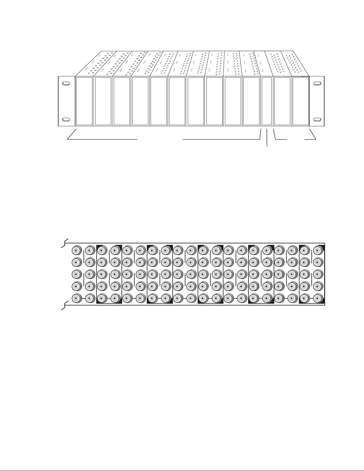
Module Placement in the Gecko 8900 Frame
There are ten slot locations in the video frame to accommodate either
analog or digital modules. These are the left ten locations. Refer to Figure 1
on page 9.
The two slots on the right are allocated for the power supplies. For additional information concerning the Power Supply module, refer to the 8900
Power Supply manual.
8900TX
Frame
8900TF
Frame
8900TFN
Frame
The third slot from the right is allocated for the Frame Monitor or 8900NET
Network Interface module. These module provide the interface for SMPTE
269M fault reporting (health alarm). For additional information concerning
the 8900NET module, refer to the 8900NET Instruction Manual.
8 8950ADC Instruction Manual
Page 9
1.
3.
Figure 1. Gecko 8900 Series Frame
Installation
8208_04r1
10
J1 J2
O
J3 J4
U
T
J5 J6
J7 J8
J9 J10
IN
9
J1 J2
J2
O
J3 J4
J4
U
T
J5 J6
J6
J7 J8
J8
J9 J10
IN
Any 8900 Module
Power
Supplies
Frame Controller or
(only)
8900NET Network
Interface Module
8900 module slots are interchangeable within the frame. There are 10 BNC
connectors in each slot’s I/O group. The functional assignment of each connector in a group is determined by the module that is placed in that slot.
The maximum number of modules a Gecko 8900 frame can accept is ten.
Figure 2 illustrates the rear connector plate for a Gecko 8900 frame.
Figure 2. Gecko 8900 Series Frame Rear Connectors
8
J1 J2
O
J3 J4
U
T
J5 J6
J7 J8
J9 J10
IN
7
J1 J2
J2
O
J3 J4
J4
U
T
J5 J6
J6
J7 J8
J8
J9 J10
IN
6
J1 J2
O
J3 J4
U
T
J5 J6
J7 J8
J9 J10
IN
5
J1 J2
J2
O
J3 J4
J4
U
T
J5 J6
J6
J7 J8
J8
J9 J10
IN
4
J1 J2
O
J3 J4
U
T
J5 J6
J7 J8
J9 J10
IN
3
J2
J1 J2
O
J4
J3 J4
U
T
J6
J5 J6
J8
J7 J8
J9 J10
IN
2
J1 J2
O
J3 J4
U
T
J5 J6
J7 J8
J9 J10
IN
1
J1 J2
O
J3 J4
U
T
J5 J6
J7 J8
J9 J10
IN
0603-03
To install a module in the frame:
Insert the module, connector end first, with the component side of the
module facing to the right and the ejector tab to the top.
2.
Verify that the module connector seats properly against the backplane.
Press the ejector tab in to seat the module in place.
8950ADC Instruction Manual 9
Page 10
Installation
Cabling
Note
At the back of every hard copy manual are die-cut overlay cards that can be
placed over the rear BNCs to identify specific 8950ADC connector functions.
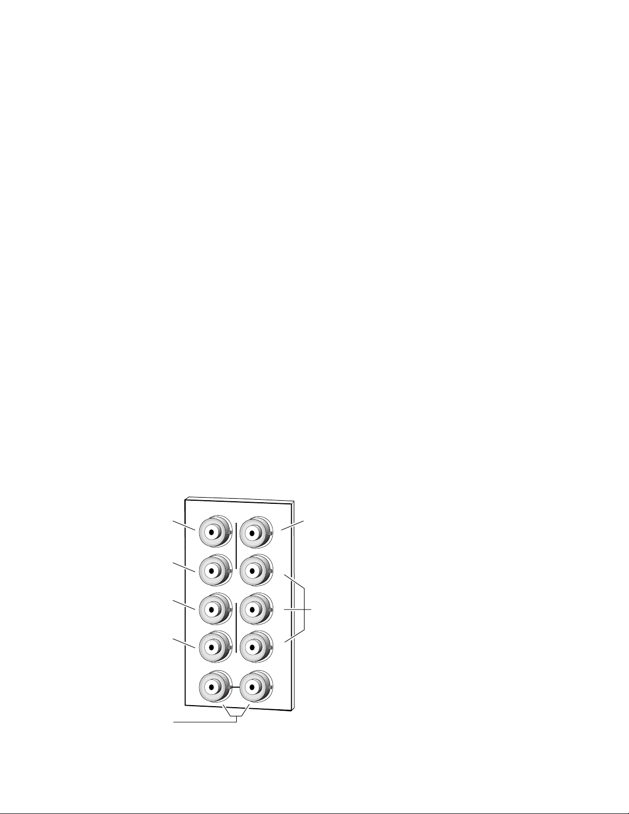
Analog Video Inputs
Connect analog component video inputs to input connectors J3, J5 and J7
(see Figure 3). The 8950ADC accepts Y, (B-Y), (R-Y) or GBR analog input,
with or without sync on the Y/G channel. For specific input signal types,
refer the Analog Inputs listed in the Specifications on page 33.
Loop-through External Sync Input
The External Sync Input is used to provide external sync for Y/G channel
inputs that do not have a sync component. There are horizontal and vertical
phase timing requirements for the Y/G and Sync input signals (see Using
External Sync on page 14 for timing considerations).
Connect a sync input source to one of the loop-through input connectors,
J9 or J10 (see Figure 3). The 8950ADC External Sync input accepts color
black or composite sync reference signal input. Terminate the unused connector into 75
Ω if the signal is not looped to other equipment.
Digital Video Outputs
Digital Output 1
R-Y/R Input
B-Y/B Input
Y/G Input
Loop-through
External Sync Input
SMPTE 259M digital are output on BNC J1 and J2 from the Y, (B-Y), (R-Y)
or GBR analog component signal. Destination equipment should have a
75
Ω input impedance or loop through inputs that are terminated into 75 Ω .
Figure 3. 8950ADC Input/Output Connectors
J3
J5
J7
DAx
O
U
T
J9 J10
IN
J2
J4
J6
J8
J2J1
J4
J6
J8
Digital Output 2
Not Used
0603-02
10 8950ADC Instruction Manual
Page 11
Power Up
Operation Indicator LEDs
Power Up
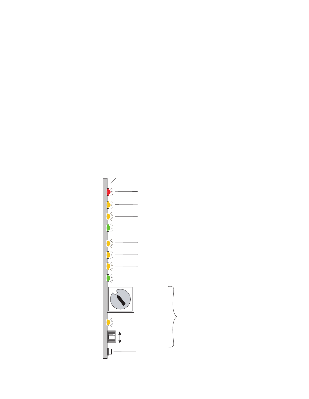
The front LED indicators and configuration switches are illustrated in
Figure 4. On power-up the green PWR LED should light and the yellow
CONF LED should illuminate for the duration of module initialization.
With factory default configuration and a valid input signal connected, the
green PWR LED, and one of the yellow signal standard LEDs (525 or 625)
should illuminate (refer to Table 2 on page 12 to see the possible operating
indicator combinations).
Video input presence is indicated by an illuminated VID PRES LED and the
appropriate 525 or 625 LED. The 525 or 625 LED will illuminate to indicate
detection of a 525-line or 625-line input signal. The VID PRES LED indicates the presence of valid composite sync on the Y/G channel or reference
input.
Figure 4. LEDs and Configuration Switches
Ejector Tab
FAULT – Red LED is off during normal operation
COMM (Yellow)
CONF (Yellow)
PWR – Green LED on indicates power OK
525 – Yellow LED on indicates 525 mode input
MAN MODE – Yellow LED on indicates manual input selection
625 – Yellow LED on indicates 625 mode input
VID PRES – Green LED on indicates a valid video input signal is present
5
6
4
7
3
8
2
9
A
B
C
16-position
Rotary switch
1
0
F
E
D
Module Configuration Switches and LED
2nd Function
(Yellow)
Momentary toggle switch
0603_06r1
GND
8950ADC Instruction Manual 11
Page 12

Power Up
A red FAULT LED indicates an error situation and, with the previously
described LEDs, can indicate the operational conditions presented in
Table 2. The table describes signal output and LED indications for various
input/reference combinations and user settings.
Table 2. Indicator LEDs and Conditions Indicated
LED Indication Condition
FAULT
(red)
COMM
(yellow)
CONF
(yellow)
PWR
(green)
1
525
(yellow)
MAN MODE
(yellow)
1
625
(yellow)
VID PRES
(green)
2ND
(yellow)
1
In Auto mode, this LED changes status depending on input signal.
Off Normal operation.
On continuously Module has detected a CPU problem or FPGA programming problem.
Flashing Configuration problems. Check inputs and settings.
Off No activity on frame communication bus.
Long flash Location Command received by the module from a remote control system.
Short flash Activity present on the frame communication bus.
Off Module is in normal operating mode.
On continuously Module is initializing, changing operating modes or updating firmware.
Flashing
Off No power to module or module’s DC/DC converter failed.
On continuously Normal operation, module is powered.
Off No input signal is present, or 625 input is present.
On continuously Input signal is 525 standard.
Flashing 525 standard input signal is manually selected, but actual signal is 625 standard.
Off Module will automatically detect and accept either input signal format.
On Input is forced by configuration to accept one format, either 525 or 625.
Off No input signal is present, or 525 input is present.
On continuously Input signal is 625 standard.
Flashing 625 standard input signal is manually selected, but actual signal is 525 standard.
Off No valid input signal is present.
On
Off First bank of rotary switch selected.
On Second bank of rotary switch selected.
Indicates rate of change of toggle switch controlled analog setting. The longer the
switch is held, the more the flashing rate and the change-of-setting rate increases.
A video input signal is present and there is valid composite sync on the Y/G channel
or reference input.
12 8950ADC Instruction Manual
Page 13

Configuration
The 8950ADC can be configured locally using onboard switches or
remotely using the 8900NET network interface GUI or a networked control
panel.
Refer to the following sections for configuration instructions:
•Configuration Summary (page 13)
• Local Onboard Module Configuration (page 18)
•Remote Control and Monitoring (page 20)
Operation of these control types is explained in detail in their respective
sections of this manual.
Configuration
Configuration Summary
This section provides a summary of all parameters that can be configured
on the 8950ADC module. Table 4 on page 16 provides a summary in table
format of all parameters and their ranges, default values, and remote, local,
and control panel function names and locations for setting each value.
Format Selections
The 8950ADC converts any one of the following analog Color Difference or
GBR video signals to a SMPTE 259M (270 Mb/s) D1 serial component
digital signal:
•SMPTE
•GBR
• Beta (US/525)
• Beta (Japan/525)
•MII (US/525)
•MII (Japan/525)
• EBU N10 (625)
Once a format is selected, the default values for that format will be loaded
to the module. The overall factory default for the module is GBR.
8950ADC Instruction Manual 13
Page 14

Configuration
Level Adjustments
The factory (default) settings for signal processing functions are set to pass
a calibrated broadcast quality signal at optimum levels. Signal video and
black output adjustments are available to correct deficiencies in the input
signal.
Once any video or black adjustments are made, it is recommended to save
these settings on the User Settings web page (
page 29). If the format is reselected from the pulldown, the Level values
will return to the factory defaults for that format.
Timing/Blanking Adjustments
The following adjustments can be made to the signal that affect timing and
blanking:
•Horizontal delay – adjust the amount of horizontal delay in ns,
User Settings Web Page
on
•SAV /EAV positions – set the position of SAV/EAV (start active
video/end active video),
• Sync source – set the sync source of the module as Y/G Channel or
External, refer to
•Vertical blanking – set vertical blanking to Short (525 and 625 = 9 lines)
or Wide (525 = 19 lines, 625 = 25 lines).
Using External Sync
below, and
Using External Sync
The External Sync source is intended to provide sync when the Y/G component signal does not contain sync. The module is not intended to provide
auto-timing or frame sync functions. Allowable horizontal and vertical
phase differences between the Y/G signal and the external sync signal vary
depending upon the presence of sync in the Y/G signal. Table 3 provides
the phase difference tolerances. Exceeding these tolerances can produce an
incorrect output signal.
Within the tolerances shown, phase adjustment can be made using the
SAV/EAV (start active video/end active video) and output video delay
line adjustment settings described in
on page 19. Function F5, 2nd bank, adjusts output horizontal phase by
setting the position of active video in the digital output within a ± 400 ns
window. Function F4, 2nd bank provides output line delay of up to 2.5 lines
in 37 ns increments.
Local On-board Module Configuration
Table 3. Adjustable Phase Difference Between Y/G and External Sync
Y/G Input
With Y/G sync < ± 400 ns 0
No Y/G sync < ± 5 µs Up to two lines N/A
14 8950ADC Instruction Manual
H Phase
Difference
V Phase
Difference
When Out of Tolerance
Select Y/G channel for Sync Source (F2, 2nd bank),
compensate using Output delay (F4, 2nd bank)
Page 15

Standard Recognition
The module can be set to for auto recognition of the input standard or set
for manual 525 or 625.
Video Input Setup
For Beta and MII 525 signals, the input video setup can be passed through
to the output or removed.
Kalypso 0:4:4 Mode
A special compressed chroma key mode (0:4:4) can be enabled for feeding
an input to the Kalypso Production Center. This format is a special
non-standard mode implemented to support a high bandwidth color input
to a Kalypso.
Configuration
User Settings Save and Recall
A function is provided to save and recall the adjusted parameters for the
selected standard. This function is useful for saving configured parameters
because recalling a standard will return the values to the factory defaults
for that specific standard.
8950ADC Instruction Manual 15
Page 16

Configuration
Table 4 provides a complete summary of the 8950ADC processing func-
tions and a comparison of the functionality available with each control type
along with the ranges and default values for each parameter.
Table 4. Summary of 8950ADC Configuration Functions
Function
Type
Format/Standard GBR
Levels control action Independent
Y/G video level 100%
Cb/B video level 100%
Cr/R video level 100%
Adjust all black
levels together
Y/G Black level 100%
Cr/R Black level 100%
Cb/B Black level 100%
Cr/R Black Beta level 100%
Cb/B Black Beta level 100%
Cr/R Black GBR level 100%
Cb/B Black GBR level 100%
Horizontal delay
adjust
Set SAV/EAV position 29
Sync Source
Vertical Blanking Short Short or Wide
Default
––
0 ns
Y/G
Channel
Range/Choices
Resolution
SMPTE
GBR 1:7
Beta (US/525) 1:3
Beta (Japan/525) 1:4
MII (US/525) 1:1
MII (Japan/525) 1:2
EBU N10 (625) 1:5
Independent or
Locked
50 to 126.4%
(0.8% steps)
48 to 126.4%
(0.8% steps)
51.2 to 126.4%
(0.8% steps)
84.3 to 158%
(0.29% steps)
41.4 to 104.9%
(0.29% steps)
40.8 to 103.7%
(0.29% steps)
41.4 to 105%
(0.29% steps)
40.8 to 103.7%
(0.29% steps)
84.3 to 158.2%
(0.29% steps)
84.3 to 158.2%
(0.29% steps)
0 to 148000 ns
(37 ns steps)
0 to 255
(1 unit steps)
Y/G Channel or
External
Web Page/
Function Name
Levels/
Format/Standard pulldown
Levels/
Control Action pulldown
1
1
1
Control Action set to Locked
1
Cr/R Black Beta (%) control
Cb/B Black Beta (%) control
Cr/R Black GBR (%) control
Cb/B Black GBR (%) control
Horizontal Delay (ns) control
Levels/
Y/G Video (%) control
Levels/
Cb/B Video (%) control
Levels/
Cb/B Video (%) control
Levels/
Levels/
Y/G Black (%) control
Levels/
Cr/R Black (%) control
Levels/
Cb/B Black (%) control
Levels/
Levels/
Levels/
Levels/
Timing/Blanking/
Timing/Blanking/
EAV/SAV Position control
Timing/Blanking/
Sync Source pulldown
Timing/Blanking/
Vertical Blanking pulldown
Rotary Switch
Bank/Setting
1:6
1:8 CNAC
1:A YGCI
1:B CBCI
1:C CRCI
1:9 –
1:D YGBI All formats
1:E CBBI
1:F CRBI
1:E CBLB
1:F RBLB
1:E BBLG
1:F RBLG
2:4 HDZI
2:5 ESVI
2:2 SSRC
2:6 VBLK
Newton
Control
Panel
RCSD
Notes/
Conditions
Selecting format
recalls factory
defaults for that
standard.
Adjust each
video level separately or tie controls together.
All formats.
Use any black
control
SMPTE,
MII (US/525),
MII (Japan/625)
EBU N10 (625)
Beta (US/525)
Beta (Japan/525)
GBR format
See
Timing/Blanking
Adjustments
page 14
See
ing/Blanking
Adjustments
page 14
on
Tim-
on
16 8950ADC Instruction Manual
Page 17

Table 4. Summary of 8950ADC Configuration Functions
Function
Type
Standard Recognition Auto
Input Video Setup
Kalypso 0:4:4 Mode Off On or Off
Recall User Settings – –
Save User Settings – –
Get Factory Defaults GBR values –
1
Value ranges include all formats and lower ranges will vary between formats.
Default
Remove
Setup
Range/Choices
Resolution
Auto, Manual 525,
or Manual 625
Remove Setup or
Pass Setup
Function Name
Standard Selection/
Standard Recognition
Standard Selection/
Input Video Setup pulldown
Standard Selection/
Kalypso 0:4:4 Mode pulldown
User Settings/
Recall User Settings
User Settings/
Save User Settings
User Settings/
Get Factory Default
Web Page/
pulldown
button
button
button
Rotary Switch
Bank/Setting
(Down 1X=Manual,
Down 2X=525
Down 3X=625)
(press down 3X
successively)
Newton
Control
Panel
2:1
RCSD
2:3 OVSP
2:E KALM
2:F N/A
2:F
N/A
N/A
Configuration
Notes/
Conditions
Beta and MII
US/525 formats
only
See
Kalypso
0:4:4 Mode
page 15
Save Levels
settings after
configuration
Module factory
default is GBR
on
8950ADC Instruction Manual 17
Page 18

Configuration
Onboard Module Configuration Switches and LEDs
The 8950ADC module can be configured locally using the rotary and
paddle switches shown in Figure 5 on page 18. The CONF and 2ND function LEDs are configuration status indicators. These four components
perform the following:
• Function (rotary) switch — This switch is used to access a desired function for configuration. The switch addresses two banks of functions;
each bank has 16 possible positions (0 through 9 and A through F). Not
all positions are used (see Table 5 on page 19). The alternate bank of
functions is accessed each time the Function Switch makes a complete
revolution past zero: While in Bank 1, a complete revolution past zero
accesses Bank 2; while in Bank 2, a complete revolution past zero
accesses Bank 1. The 2ND LED indicates which bank is currently being
accessed.
CONF – configuration LED
LOCAL
JP2
REMOTE
JP2
Note
The Function switch should be kept in the position for the selected mode (1
through 7) or in position 0 when not in use to avoid any inadvertent change
in configuration. 0 is an inactive position.
•SW2 (paddle) switch — Actuates or selects the desired setting for the
selected function when the switch is held momentarily in either the up
or down position.
•2ND LED — When on, indicates that user is accessing the second bank
of configuration parameters.
• CONF (configuring) LED — When on, indicates the module is initializing or processing configuration information.
Figure 5. Module Configuration Switches and LEDs
671-4799-
FUNCTION – rotary switch
2nd – second function LED
SW2 – paddle switch
GRASS VALLEY GROUP 8950ADC
18 8950ADC Instruction Manual
0603_05r1
Page 19

Local On-board Module Configuration
1. Rotate the Function Switch to the desired function (see Table 5). Also
refer to Table 4 on page 16 for a summary in table format of all
parameters and their ranges, and default values.
2. Move the paddle switch up or down to set the desired function
parameter. Some parameters require that the paddle switch be moved
more than once in succession.
Table 5. 8950ADC Local On-board Configuration Functions
Configuration
Function
Switch
0----Inactive position
1 MII (US/525) -- Recalls default parameters for MII (US/525) standard.
2 MII (Japan/525) -- Recalls default parameters for MII (Japan/525) standard.
3 BETA (US/525) -- Recalls default parameters for BETA (US/525) standard.
4 BETA (Japan/525) -- Recalls default parameters for BETA (Japan/525) standard.
5 EBU N10 (625) -- Recalls default parameters for EBU N10 625 standard.
6 SMPTE -- Recalls default parameters for SMPTE standard.
7 GBR -- Recalls default parameters for GBR standard.
8 Increase Decrease Input video level adjustment for all channels (Y, Cb/B, Cr/R) together.
Bank 1
9 Increase Decrease Input black level adjustment for all channels (Y, Cb/B, Cr/R) together.
A Increase Decrease Y/G input video level adjustment.
B Increase Decrease Cb/B input video level adjustment.
C Increase Decrease Cr/R input video level adjustment.
D Increase Decrease Y/G input black level adjustment.
E Increase Decrease Cb/B input black level adjustment.
F Increase Decrease Cr/R input black level adjustment.
0----Inactive position
1 Auto
2 Sync on G/Y Ext Ref In Sync mode selection determines the sync source.
3 Pass Remove Pass or remove setup level from 525 Beta or MII only.
4 Increase Decrease Horizontal video delay line adjustment in 37 ns steps to maximum 2.5 lines.
Bank 2
5 Increase Decrease
6 Short Wide Vertical blanking.
7 thru D Currently not used
E Off On Turn 0:4:4 Kalypso mode On or Off.
F Recall
1
Subsequent presses toggle between 525 and 625.
Paddle
Switch Up
Paddle
Switch Down
Manual
Down x 2 Manually sets 525 line standard.
Down x 3
Save
(Down x 3)
Standard recognition – Paddle switch up enables automatic input standard recognition. First press down enables manual selection; second press selects 525 standard,
and third press selects 625 standard.
1
Manually sets 625 line standard.
SAV/EAV (start active video/end active video) delay adjustment. The default value is
correct for the sync source on the Y/G channel.
Recall previously saved configuration or Save current configuration settings by pressing paddle down 3 X. Recycling module power restores the most recent state.
Function Description
8950ADC Instruction Manual 19
Page 20

Configuration
Remote Configuration and Monitoring
8950ADC configuration and monitoring can be performed using a web
browser GUI interface or a networked Newton Control Panel when the
8900NET Network Interface module is present in the video frame (Gecko
8900TFN-V frame). Each of these interfaces is described below.
Note For remote access, make sure the jumper block on the module is set for both
Local and Remote access (Figure 5 on page 18).
8900NET Module Information
Refer to the 8900NET Network Interface Module Instruction Manual for
information on the 8900NET Network Interface module and setting up and
operating the Gecko 8900 frame network.
Note The 8900NET module in the frame must be running software version 3.2.0 or
higher for proper remote and control panel operation. Upgrade software and
instructions for the 8900NET can be downloaded from the Grass Valley web
site.
Newton Control Panel Configuration
A Newton Control Panel (hard or soft version) can be interfaced to the
Gecko 8900 Series frame over the local network. Refer to the documentation that accompanies the Newton Modular Control System for installation, configuration, and operation information.
Control panel access offers the following considerations for module configuration and monitoring:
•Ability to separate system level tasks from operation ones, minimizing
the potential for on-air mistakes.
•Ability to group modular products—regardless of their physical locations—into logical groups (channels) that you can easily manipulate
with user-configured knobs.
•Update software for applicable modules and assign frame and panel IP
addresses with the NetConfig Networking application.
•Recommended for real-time control of module configuration parameters, providing the fastest response time.
Note Not all module functions are available with the control panel, such as E-MEM
and factory default recalls. The available control panel controls for the
8950ADC module are listed in Table 4 on page 16.
An example of the Newton Configurator is shown in Figure 6 on page 21.
20 8950ADC Instruction Manual
Page 21

Figure 6. Newton Configurator Example
Configuration
Web Browser Interface
The web browser interface provides a graphical representation of module
configuration and monitoring.
Use of the web interface offers the following considerations:
•Provides complete access to all module status and configuration func-
tions, including naming of inputs and outputs, factory parameter and
name default recalls, E-MEM functions, slot configuration, and SNMP
monitoring controls.
•Web access will require some normal network time delays for pro-
cessing of information.
•Configuration parameter changes may require pressing
Enter, upload processing time, and a manual screen refresh to become
effective.
•Web interface recommended for setting up module signal and slot
names, E-MEMS, and reporting status for SNMP and monitoring.
Refer to the Frame Status page shown in Figure 7 on page 22. The 8900
modules can be addressed by clicking either on a specific module icon in
the frame status display or on a module name or slot number in the link list
on the left.
Apply button or
8950ADC Instruction Manual 21
Page 22

Configuration
Note The physical appearance of the menu displays on the web pages shown in
this manual represent the use of a particular platform, browser and version
of 8900NET module software. They are provided for reference only. Displays
will differ depending on the type of platform and browser you are using and
the version of the 8900NET software installed in your system. This manual
reflects 8900NET software version 3.2.2.
For information on status and fault monitoring and reporting shown on the
Status page, refer to Status Monitoring on page 36.
Figure 7. Gecko 8900 Frame Status Page
The Links section lists the frame and its current modules. The selected link's Status
page is first displayed and the sub-list of links for the selection is opened. The sub-list
allows you to select a particular information page for the selected device.
Content display section displays the information page
for the selected frame or module (frame slot icons are also
active links).
Refresh button for manual
update of page
0603_08
22 8950ADC Instruction Manual
Page 23

8950ADC Links and Web Pages
The 8900 GUI provides the following links and web pages for the 8950ADC
module (Figure 8):
• Status – reports input and reference signal status and module informa-
tion (page 24),
• Levels – select operating format for module and adjust video and black
levels (page 25),
•Timing/Blanking – adjust horizontal timing, select SAV/EAV, sync
source, and vertical blanking width (page 27),
• Standard Selections – select standard recognition method, add or
remove output video setup, and turn Kalypso 0:4:4 compressed chroma
key signal on or off (page 28),
•User Settings – Save or recall user settings, select factory defaults
(page 29),
• Slot Config – provides a Locate Module function and Slot Memory and
SNMP reporting status information (page 30), and
Configuration
• Software Update – provides information on software updating
(page 32).
Figure 8. 8950ADC Web Page Links
Refer to Table 4 on page 16 for a summary in table format of all parameters
and their ranges, and default values.
8950ADC Instruction Manual 23
Page 24

Configuration
Status Web Page
Use
this
link
The Status web page (Figure 9) shows the input signal status of the component analog video input. Color coding of the display indicated the signal
status. Refer to Status Monitoring on page 36 for an explanation of the color
coding.
Information about the module, such as part number, serial number, hardware revision and software and firmware versions are given in a read-only
section at the bottom of the display.
Figure 9. 8950ADC Status Web Page
24 8950ADC Instruction Manual
Page 25

Use
this
link
Configuration
Levels Web Page
The Levels web page (Figure 10) provides adjustment for the following
module parameters:
• Format and standard selection,
•Video levels (all channels together or individually), and
• Black levels (all channels together or individually).
Press the
Figure 10. Levels Web Page for SMPTE, M II, and EBU N10
Apply button when required after a selection to enter the value.
Format/Standard Selection
Select a component standard from the pulldown choices. The default
parameters for that standard will be recalled to the module.
8950ADC Instruction Manual 25
Page 26

Configuration
Video and Black Levels
If required, Video and Black levels for each channel can be adjusted as
needed after the selected format defaults have been loaded.
Levels can be set in
or in
Locked mode (all channels at once with any of the three controls). Use
the
Control Action pulldown to select either Independent or Locked.
Make Level adjustments with the controls provided. You may use the
arrow controls or enter a number with the keyboard.
If you have made level changes, save these if desired with the Save User
Settings function (see User Settings Web Page on page 29).
Horizontal delay, sync source, and vertical blanking are not changed by
this reset so these user adjustments are retained. This differs from the
Factory Defaults function which returns these values to factory calibration.
The Level web pages differ slightly between formats. The Black controls
will be labeled differently for the specific formats.
Independent mode (Y/G, Cb/B, and Cr/R individually)
Get
26 8950ADC Instruction Manual
Page 27

Use
this
link
Configuration
Timing/Blanking Web Page
Set the following parameters on the Timing/Blanking web page:
• Amount of Horizontal Delay in ns,
• Position of EAV/SAV (end active video/start active video),
• Sync source (Y/G Channel or External), and
• Short or Wide vertical blanking.
The Timing/Blanking web page is shown in Figure 11.
Figure 11. Timing/Blanking Web Page
8950ADC Instruction Manual 27
Page 28
Configuration
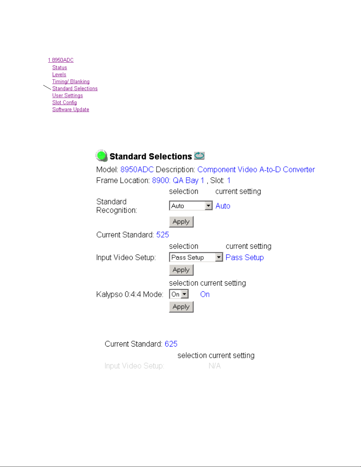
Standard Selections Web Page
The Standards Selection web page shown in Figure 12 (for a 525 standard)
is used to select the following module parameters:
Use
this
link
• Standard Recognition (auto or manual,)
• If
Manual is selected, set signal standard (525 or 625),
•Output video setup add or remove (in 525 line rate only), this control is
grayed out in a 625 standard as shown in Figure 13, and
• Enable Kalypso 0:4:4 Mode (compressed chroma key input mode for
Thomson Grass Valley Kalypso Video Production Center).
Figure 12. Standard Selection Web Page – 525 Signal
Figure 13. Standard Selection – 625 Signal
28 8950ADC Instruction Manual
Page 29

User Settings Web Page
The User Settings web page (Figure 14) allows you to set the following
parameters:
Configuration
Use
this
link
•Recall previously user setting with
• Save the currently selected settings for the entire module by selecting
the
Save User Settings button, and
•Recall the GBR factory default video levels and timing settings on the
module using the
Figure 14. User Settings Web Page
Get Factory Defaults button.
Recall User Settings button,
8950ADC Instruction Manual 29
Page 30

Configuration
Use
this
link
Slot Config Web Page
Use the Slot Config web page (Figure 15 on page 31) to perform the following functions on the 8950ADC module:
•
Locate Module – selecting the Flash radio button flashes the yellow
COMM and CONF LEDs on the front of the module so it can be located
in the frame.
•
Slot Identification – you may identify the module by typing a specific
name in the
module and travels with the 8900NET module if it is moved to another
frame. Select
•
Slot Memory – the slot configuration for each media module is automati-
cally saved periodically (once an hour) to the 8900NET module in that
frame. You may also select the
save the current configuration for this slot. The configuration is saved
on the 8900NET module. If the 8900NET module is removed or
powered down, the stored configurations are not saved.
Name field. The assigned name is stored on the 8900NET
Default to enter the factory default module name.
Learn Module Config button at any time to
When the
ration saved to this slot is saved as slot memory. When the current
module is removed and another module of the same type is installed,
the configuration saved to the 8900NET module will be downloaded to
the new module. The box must be checked before the current module
with the saved configuration is removed.
•
Frame Heath Reporting – this function is not active with the latest version
of the 8900NET module that controls this page.
•
Hardware Switch Controls – a read-only status report of 8900NET module
switch settings for Module Status Reporting and Asynchronous Status
Reporting. These functions must be enabled for the following Slot
SNMP Trap Reports to function.
Slot SNMP Trap Reports – displayed only when the SNMP Agent software
•
has been installed on the 8900NET module. Slot SNMP traps can be
enabled only when the hardware switches for Module Fault reporting
and Asynchronous Status reporting are in enabled on the 8900NET
module (dipswitch S1 segment 5 and dipswitch S2 segment 1).
The enabled SNMP traps will be reported to any SNMP manager that
is identified as an SNMP Report Destination in 8900NET configuration.
Trap severity is read-only hard-coded information that is interpreted
and responded to by the SNMP Manager software configuration.
Restore upon Install box has been checked, the current configu-
30 8950ADC Instruction Manual
Page 31

Figure 15. 8950ADC Slot Config Web Page
Configuration
8950ADC Instruction Manual 31
Page 32

Configuration
Use
this
link
Software Update Web Page
The Software Update page (Figure 16) indicates that module software
updates via the web or using the NetConfig networking application are not
supported. For instructions on updating to the latest software, refer first to
the 8950ADC Release Notes that accompany the software update for complete details.
Currently, the only recommended method of software updating is done
with a software kit (8900-FLOAD-CBL) that includes a CD-ROM with the
current software files and a serial cable assembly available from Grass
Valley.
Refer to the 8900-FLOAD-CBL Software Upgrade Instruction Manual in
PDF format on the CD-ROM for complete updating instructions and the
required software files for the module.
Figure 16. 8950ADC Software Update Web Page
32 8950ADC Instruction Manual
Page 33

Specifications
Specifications
Table 6. 8950ADC Specifications
Parameter Value
Analog Component Input
Signal type SMPTE, GBR, EBU N10, Beta (US), Beta (Japan), MII (US),
MII (Japan)
Number of inputs 3: Y, (B-Y), (R-Y) or G, B, R
Connector type 75 Ω BNC
Signal level 1 Vpp +15% max (Y or G channel)
0.7Vpp +15% [(B-Y), (R-Y) or B, R channels]
Return loss > 40 db to 5.5 MHz
External Sync Input
Signal type Color black: 140 mV to 560 mV / Composite sync: 600 mV to 3 V
Number of inputs 1 loop-through
Connector type 75 Ω BNC
Impedance Hi Z (> 10k)
Return loss > 40 db to 5.5 MHz
Digital Outputs
Number of outputs 2
Connector type 75 Ω BNC
Signal formats SMPTE 259M
Return loss > 18 dB, 5 MHz - 270 MHz
Error handling EDH embedded
Performance
Standards Input: 525 or 625 (auto or manual)
Sampling 4 times over-sampling
Input A/D 10 bits
Frequency response Y,G,B,R: ±0.1 dB (10 Hz to 5.5 MHz)
(R-Y), (B-Y): ±0.1 dB (10 Hz to 2.75 MHz)
Group delay error Y: < 5 ns peak to peak (10 Hz to 5.5 MHz)
(R-Y), (B-Y): < 5 ns peak to peak (10 Hz to 2.75 MHz)
Propagation delay 2.5 µs GBR input; 2.1 µs Y(B-Y) (R-Y) input
Delay control (user) Up to 2.5 line (37 ns increments)
Relative timing of CAV outputs Y to B-Y and R-Y within 2 ns
K-factor 2T pulse K < 0.4%
Vertical blanking 525:
Narrow (short) – 9 lines
Wide – 19 lines
625:
Narrow (short) – 9 lines
Wide – 25 lines
Input gain control ± 50% ± 20%
Black level setup Manual, all channels (±15%)
Signal-to-noise ratio ≥ 60 dB
8950ADC Instruction Manual 33
Page 34

Specifications
Table 6. 8950ADC Specifications - (continued)
Parameter Value
Environmental
Frame temperature range See Gecko 8900 Frame specifications
Operating humidity range 0 to 90% non-condensing
Non-operating temperature -10 to 70 ° C
Mechanical
Frame type Gecko 8900 Series
Size 2 RU
Power Requirements
Supply voltage +12 V
Power consumption ≤ 7.2 Watts ±5%
34 8950ADC Instruction Manual
Page 35

Service
Service
The 8950ADC modules make extensive use of surface-mount technology
and programmed parts to achieve compact size and adherence to
demanding technical specifications. Circuit modules should not be serviced in the field unless directed otherwise by Customer Service.
If your module is not operating correctly, proceed as follows:
•Check frame and module power and signal present LEDs.
•Verify power at the voltage testpoints (Figure 17) and check Fuse F2 (on
the back of the module circuit board) if no voltage is detected.
•Check for presence and quality of input signals.
•Verify that source equipment is operating correctly.
•Check cable connections.
Refer to Figure 4 for the location of PWR LED and Table 2 on page 12 for
proper LED indications.
If the module is still not operating correctly, replace it with a known good
spare and return the faulty module to a designated Grass Valley repair
depot. Call your Grass Valley representative for depot location.
Refer to the Contacting Grass Valley at the front of this document for the
Grass Valley Customer Service Information number.
Figure 17. 8950ADC Fuse and Voltage Testpoint Locations
Voltage Testpoints
JP8
GND
JP8
-5V
GRASS VALLEY GROUP 8950ADC
+3V
+5V
671-4799-
Fuse
Solder side
(back)
F1.5A 125V
F2
0603_07
8950ADC Instruction Manual 35
Page 36

Status Monitoring
Status Monitoring
This section provides a summary of status monitoring and reporting for a
Gecko 8900 Series system. It also summarizes what status items are
reported and how to enable/disable reporting of each item. There are a
number of ways to monitor status of modules, power supplies, fans and
other status items depending on the method of monitoring being used.
8900 Frame status will report the following items:
• Power supply health,
• Status of fans in the frame front cover,
•Temperature,
•Module health, and
• Frame bus status.
Module health status will report the following items:
• Internal module state (and state of submodule or options enabled)
including configuration errors (warning), internal faults, and normal
operation (Pass).
LEDs
• Signal input states including valid/present (pass), not present or
invalid (warning), not monitored, and not available (no signal inputs).
•Reference input states including locked/valid (pass), not
locked/invalid (warning), and not monitored.
• Signal output states with reporting functionality (reference output).
LEDs on modules in the frame and on the front of the 8900TF/TFN frames
indicate status of the frame and the installed power supplies, fans in the
front covers, and modules. (The 8900TX-V/A frames have no LED indicators on the front cover.)
When a red FAULT LED is lit on a frame front cover, the fault will also be
reported on the 8900NET or Frame Monitor module. The LEDs on the front
of these modules can then be read to determine the following fault conditions:
• Power Supply 1 and 2 health,
• Fan rotation status,
• Frame over-temperature condition,
• Frame Bus fault (8900NET only), and
•Module health bus.
36 8950ADC Instruction Manual
Page 37

Frame Alarm
Status Monitoring
In general, LED colors used on the frame and modules indicate:
•Green – normal operation, (Pass) or signal present, module locked.
•Red – On continuously = fault condition, flashing = configuration error.
•Yellow – On continuously = active condition (configuration mode or
communication), flashing in sequence = module locator function.
Status LEDs for this module are described in Operation Indicator LEDs on
page 11. LEDs for the 8900NET module are described in the 8900NET
Network Interface Instruction Manual.
A Frame Alarm connection is available on pins 8 and 9 of the RS-232 connector on the rear of 8900 frame (Frame Monitor or 8900NET Network
Interface module required). This will report any of the status items enabled
with the 8900NET or Frame Monitor module configuration DIP switch.
Connection and use of the Frame Alarm is covered in detail in the 8900NET
Network Interface Instruction Manual.
Web Browser Interface
When the 8900NET module is installed in the frame, a web browser GUI
can indicate frame and module status on the following web pages:
• Frame Status web page – reports overall frame and module status in
graphical and text formats.
•Module Status web page – shows specific input and reference signal
status to the module along with enabled options and module versions.
•A Status LED icon on each web page to report communication status
for the frame slot and acts as a link to the Status web page where warnings and faults are displayed (8900NET version 3.0 or later).
In general, graphics and text colors used indicate the following:
•Green = Pass – signal or reference present, no problems detected.
•Red = Fault – fault condition.
•Yellow = Warning – signal is absent, has errors, or is mis-configured.
•Gray = Not monitored (older 8900 module).
•White = Not present.
Status reporting for the frame is enabled or disabled with the configuration
DIP switches on the 8900NET module. Some module status reporting items
can also be enabled or disabled on individual configuration web pages.
8950ADC Instruction Manual 37
Page 38

Status Monitoring
SNMP Reporting
The Gecko 8900 Series system uses the Simple Network Monitoring Protocol (SNMP) internet standard for reporting status information to remote
monitoring stations. When SNMP Agent software is installed on the
8900NET module, enabled status reports are sent to an SNMP Manager
such as the Grass Valley’s NetCentral application.
There are both hardware and software report enable switches for each
report. Both must be enabled for the report to be sent. Software report
switches are set on the 8900NET Configuration web page for the Frame, the
8900NET module, and each module slot. Refer to the 8900NET Network
Interface Instruction Manual for installation instructions.
38 8950ADC Instruction Manual
Page 39

Functional Description
The 8950ADC converts an analog CAV or GBR video signal to the SMPTE
259M (270Mb/s) D1 serial component digital signal. The major functional
blocks are:
• Input buffers, amplifiers and low pass filters (LPF)
•Analog to digital converters (ADC)
•Digital Signal Processing (DSP) Field Programmable Gate Array
(FPGA)
•Digital to Analog Converters
• Input Phase Lock Loop (PLL) and 54 MHz clock generator
• Serializer
•Delay line
•Embedded processor
Refer to the block diagram in Figure 18 while reading the following functional description.
Functional Description
Figure 18. 8950ADC Block Diagram
Reference
Sync
Y/G
A
(B-Y)/B
A
(R-Y)/R
A
LEDs
User
Setup
DAC
DAC
DAC
LPF
LPF
LPF
Clamp
Mux
Reference Selection
Parallel Interface
I2C
Interface
ADC
ADC
ADC
Sync
Separator
10 bit+1
10 bit+1
10 bit+1
54 MHz
Delay Line
(2.5 max.)
D1 Parallel
FPGA
Digital Signal
Processing
Timing
Sync Generator
Standard Detector
Filters
Color Space
Converter
Serializer
Serial
Output
27 MHz
To Host
Embedded
Processor
VCXO
54 MHz
Loop
Filter
Phase
Comp.
0603_01
8950ADC Instruction Manual 39
Page 40

Functional Description
Input Buffers/Amplifiers/Low Pass Filters
Analog to Digital Converters
Digital Signal Processor FPGA
Three-channel input Clamping Video Amplifiers support the professional
studio TV standard with 20 MHz bandwidth and > 60dB signal to noise
ratio. Black level voltage is under CPU control (DC feedback D/A converters). Signals are passed from the amplifiers to three identical Low Pass
Filters (LPF), where all spectral components above 15 MHz are removed
from incoming signals.
The three 10-bit ADCs have a 54 MHz sampling rate, and perform high
speed analog to digital conversion on the signals received from the LPFs.
The DSP FPGA performs the following signal processing:
• Input Signal Processor
After analog to digital conversion, the digitized video signal passes
through the Digital Input Signal Processor. This controls the gain of all
three input signals individually in the range of ± 15%. User input gain
control is also available through Embedded Processor. The clipping
circuit preludes overshooting errors in cases where either the input
signal level or amplifier gain is too high.
•Color Space Converter
The 8950ADC supports Y, (B-Y), (R-Y) or GBR input, and the Color
Space Converter automatically connects to the appropriate signal path.
The Color Space Converter converts an incoming GBR signal to Y,
(B-Y), (R-Y) according to the D1 Color space matrix.
• Sync Processor
The Sync Processor contains the H&V Extractor, Frame Pulse Extractor,
Standard Detector, and PLL Phase Detector Input Signal. (The Analog
Sync Separator and PLL Phase Detector are not part of the FPGA.)
• Filters and Decimators
The DSP FPGA performs Low Pass filtering (6 MHz bandwidth) and
decimation by 4 for all three channels. For the B-Y and R-Y channels the
DSP FPGA performs additional Low Pass filtering and decimation by 2
(3 MHz bandwidth).
•Control
The Control FPGA contains parallel communication blocks between
the embedded processor and FPGA.
40 8950ADC Instruction Manual
Page 41

Functional Description
Input Phase Lock Loop (PLL) and 54 MHz clock generator
From the incoming composite sync, the PLL generates a 54 MHz clock for
oversampling. This clock also servers as a free-running clock when no
input signal is present.
Delay line
The on board delay line provides a maximum 2.5 line signal delay. The
delay time is under user control in 37 ns increments.
Serializer
The Serializer is a standard D1, 10-bit, 270 MHz serializer with embedded
Error Data Handling.
Embedded processor
The embedded processor provides the interface between the user and all
the processing logic of the 8950ADC, as well as communication between
the 8950ADC and a remote host processor.
8950ADC Instruction Manual 41
Page 42

Functional Description
42 8950ADC Instruction Manual
Page 43

Index
Numerics
2ND LED 12
525 LED 12
525 line standard
local control
625 LED 12
625 line standard
local control
8900 frame
frame alarm
status reporting 36
8900-FLOAD-CBL option 32
8900NET module
installation
required software version 20
8950ADC
features
functional description 39
19
19
37
8
7
A
analog component inputs
cabling
specification 33
10
B
COMM LED 12
CONF LED 11, 12
configuration 18
overview 13
Remote, GUI 20
summary table 16
connectors 9
input 10
input/output 10
control panel 20
controller module 8
Cr/R black level
local control
remote control 26
summary table 16
Cr/R video level
local control
remote control 26
summary table 16
19
19
D
default configuration 11
digital video outputs
cabling
specifications 33
documentation online 2
10
backplane 9
block diagram 39
C
cabling 10
Cb/B black level
local control
remote control 26
summary table 16
Cb/B video level
local control
remote control 26
summary table 16
8950ADC Instruction Manual 43
19
19
E
enable SNMP 38
environmental 34
external sync 14
F
factory default 11, 14
factory defaults
remote control
summary table 16, 17
FAQ database 2
29
Page 44

Index
fault 12
FAULT LED
troubleshooting
format setup 19
frame 8, 34
frame capacity 8
Frame Monitor module 8
Frame Status page 37
frequently asked questions 2
functional description 39
fuse 35
36
G
graphical user interface (GUI) 23
Grass Valley web site 2
H
horizontal delay
local control
overview 14
remote control 27
summary table 16
horizontal phase 14
19
I
overview 15
summary table 17
Kalypso mode selection 28
L
LEDs and Configuration Switches 11
level adjustments
locking together
local control
remote control 26
overview 14
Levels web page 25
locate module 30
loop-through 10
19
M
MAN MODE LED 12
module
configuration switches
controller 8
installation 8
power supply 8
slots 9
module health status 36
Module Status page 37
18
impedance 10
indicators 12
initialization 11
input 33
buffers 40
loopthrough 10
phase lock loop 41
specification 33
input formats
local controls
overview 13
remote control 25
summary table 16
19
N
Newton Control Panel
control summary table
overview 20
O
online documentation 2
operational modes 12
outputs 33
connectors 10
specification 33
termination 10
overlay 10
16
K
Kalypso 0:4:4 mode
local control
44 8950ADC Instruction Manual
19
P
performance 33
Page 45

Index
phase differences 14
power 11, 34
power supply 8
PWR LED 11, 12
R
rear connectors 9
recall user settings 19
remote configuration
standards selection
user settings 29
repair depot 35
report enable switches 38
S
SAV/EAV position
local control
overview 14
remote control 27
summary table 16
save user settings 19
service 35
setup
input video
remote control
summary table 17
Slot Config web page 30
slot memory 30
SNMP reporting
enabling
overview 38
software download from web 2
software update
8900-FLOAD-CBL
Software Update web page 32
specifications 33
standard recognition
overview
summary table 17
status monitoring 36
Status web page 24
summary table 16
switches 18
sync 14
19
30
15
28
19, 28
32
sync output 10
sync source
local controls
overview 14
remote control 27
summary table 16
19
T
termination 10
testpoints 35
Timing/Blanking web page 27
troubleshooting 35
U
User Settings
overview
user settings
recall
summary table
save
summary table
User Settings web page 29
15
17
17
V
vertical blanking 16
local control 19
overview 14
remote control 27
specifications 33
vertical phase 14
VID PES LED 12
video input setup
overview
voltage 34
voltage tespoints 35
15
W
web browser
overview
rweb page control summary 16
web site
documentation
FAQ database 2
21
2
8950ADC Instruction Manual 45
Page 46

Index
Grass Valley 2
software download 2
Y
Y/G black level
local control
remote control 26
summary table 16
Y/G video level
local control
remote control 26
summary table 16
19
19
46 8950ADC Instruction Manual
 Loading...