

Page 1

7500 SERIES
7500NB/7500WB ROUTERS
Instruction Manual
071810700
FIRST PRINTING: JULY 2001
Page 2
Contacting Grass Valley Group
Region Voice Fax Address Web Site
North America (800) 547-8949
530-478-4148
Pacific Operations +852-2585-6688
Support: 852-2585-6579
U.K., Europe, Asia, Middle East +44 1753 218 777 +44 1753 218 757
France +33 1 45 29 73 00
Germany +49 221 1791 234 +49 221 1791 235
Copyright © Grass Valley Group. All rights reserved.
This document may not be copied, in whole or in part, or otherwise reproduced, except as specifically
permitted under U.S. copyright law, without the prior written consent of Grass Valley Group, P.O. Box
599000, Nevada City, CA 95959-7900 USA. GRASS VALLEY GROUP is a registered trademark and
Grass Valley is a trademark of Grass Valley Group. All registered trademarks and trademarks are property of their respective holders. Grass Valley Group products are covered by U.S. and foreign patents,
issued and pending. Product options and specifications subject to change without notice. The information in this manual is furnished for informational use only, is subject to change without notice, and
should not be construed as a commitment by Grass Valley Group. Grass Valley Group assumes no responsibility or liability for any errors or inaccuracies that may appear in this publication.
Online User Documentation
(530) 478-3347 Grass Valley Group
+852-2802-2996
P.O. Box 599000
Nevada City, CA 95959-7900
USA
www.grassvalleygroup.com
Current versions of product catalogs, brochures, data sheets, ordering
guides, planning guides, manuals, and release notes may be downloaded
via the Product Documentation link on the Grass Valley Group home page:
FAQ Database
Many solutions to problems and troubleshooting efforts can be found by
searching our Frequently Asked Questions (FAQ) database. To access:
Select the Service/Support link on the Grass Valley Group home page.
1.
Select the Online Support & FAQ link on the Service/Support page.
2.
Follow the directions provided to access the FAQ database and other
3.
online support services.
Software Downloads
Software updates, drivers and patches may be downloaded via the
Download link on the Grass Valley Group home page:
Page 3

Contents
Preface
About This Manual. . . . . . . . . . . . . . . . . . . . . . . . . . . . . . . . . . . . . . . . . . . . . . . . . . . . vii
Additional Documentation . . . . . . . . . . . . . . . . . . . . . . . . . . . . . . . . . . . . . . . . . . . vii
Safety Summary
Safety Terms and Symbols. . . . . . . . . . . . . . . . . . . . . . . . . . . . . . . . . . . . . . . . . . . . . . ix
Terms in This Manual. . . . . . . . . . . . . . . . . . . . . . . . . . . . . . . . . . . . . . . . . . . . . . . . ix
Terms on the Product . . . . . . . . . . . . . . . . . . . . . . . . . . . . . . . . . . . . . . . . . . . . . . . . ix
Symbols on the Product . . . . . . . . . . . . . . . . . . . . . . . . . . . . . . . . . . . . . . . . . . . . . . . x
Warnings . . . . . . . . . . . . . . . . . . . . . . . . . . . . . . . . . . . . . . . . . . . . . . . . . . . . . . . . . . . . . x
Cautions . . . . . . . . . . . . . . . . . . . . . . . . . . . . . . . . . . . . . . . . . . . . . . . . . . . . . . . . . . . . . xi
Regulatory Notices
Certifications and Compliances . . . . . . . . . . . . . . . . . . . . . . . . . . . . . . . . . . . . . . . . xiii
FCC Emission Control . . . . . . . . . . . . . . . . . . . . . . . . . . . . . . . . . . . . . . . . . . . . . . xiii
Canadian EMC Notice of Compliance . . . . . . . . . . . . . . . . . . . . . . . . . . . . . . . . . xiii
EN55022 Class A Warning. . . . . . . . . . . . . . . . . . . . . . . . . . . . . . . . . . . . . . . . . . . xiii
Canadian Certified Power Cords . . . . . . . . . . . . . . . . . . . . . . . . . . . . . . . . . . . . . xiv
Canadian Certified AC Adapter . . . . . . . . . . . . . . . . . . . . . . . . . . . . . . . . . . . . . . xiv
Laser Compliance . . . . . . . . . . . . . . . . . . . . . . . . . . . . . . . . . . . . . . . . . . . . . . . . . . xiv
Laser Safety Requirements . . . . . . . . . . . . . . . . . . . . . . . . . . . . . . . . . . . . . . . . . xiv
Laser Safety. . . . . . . . . . . . . . . . . . . . . . . . . . . . . . . . . . . . . . . . . . . . . . . . . . . . . . xiv
FCC Emission Limits. . . . . . . . . . . . . . . . . . . . . . . . . . . . . . . . . . . . . . . . . . . . . . . xv
Certification . . . . . . . . . . . . . . . . . . . . . . . . . . . . . . . . . . . . . . . . . . . . . . . . . . . . . . . . xv
Section 1 — Overview
Introduction . . . . . . . . . . . . . . . . . . . . . . . . . . . . . . . . . . . . . . . . . . . . . . . . . . . . . . . . . 1-1
System Level Architecture. . . . . . . . . . . . . . . . . . . . . . . . . . . . . . . . . . . . . . . . . . . . . 1-2
7500NB Architecture. . . . . . . . . . . . . . . . . . . . . . . . . . . . . . . . . . . . . . . . . . . . . . . . 1-2
7500WB Architecture . . . . . . . . . . . . . . . . . . . . . . . . . . . . . . . . . . . . . . . . . . . . . . . 1-7
Section 2 — Installation
Frame Installation . . . . . . . . . . . . . . . . . . . . . . . . . . . . . . . . . . . . . . . . . . . . . . . . . . . . 2-1
7500 NB Frame Installation . . . . . . . . . . . . . . . . . . . . . . . . . . . . . . . . . . . . . . . . . . 2-1
7500 WB Frame Installation . . . . . . . . . . . . . . . . . . . . . . . . . . . . . . . . . . . . . . . . . . 2-2
Module Installation. . . . . . . . . . . . . . . . . . . . . . . . . . . . . . . . . . . . . . . . . . . . . . . . . . . 2-3
7500NB Module Placement . . . . . . . . . . . . . . . . . . . . . . . . . . . . . . . . . . . . . . . . . . 2-3
7500WB Module Placement . . . . . . . . . . . . . . . . . . . . . . . . . . . . . . . . . . . . . . . . . . 2-4
Cabling . . . . . . . . . . . . . . . . . . . . . . . . . . . . . . . . . . . . . . . . . . . . . . . . . . . . . . . . . . . . . 2-5
7500 Series Instruction Manual iii
Page 4

Contents
7500NB Backplane Cabling . . . . . . . . . . . . . . . . . . . . . . . . . . . . . . . . . . . . . . . . . . . 2-6
7500NB Backplane Cabling . . . . . . . . . . . . . . . . . . . . . . . . . . . . . . . . . . . . . . . . . . . 2-8
Pinouts . . . . . . . . . . . . . . . . . . . . . . . . . . . . . . . . . . . . . . . . . . . . . . . . . . . . . . . . . . . 2-10
Communications. . . . . . . . . . . . . . . . . . . . . . . . . . . . . . . . . . . . . . . . . . . . . . . . . . . 2-13
7500NB Ethernet . . . . . . . . . . . . . . . . . . . . . . . . . . . . . . . . . . . . . . . . . . . . . . . . . 2-13
7500WB Ethernet. . . . . . . . . . . . . . . . . . . . . . . . . . . . . . . . . . . . . . . . . . . . . . . . . 2-16
Global Serial Channel. . . . . . . . . . . . . . . . . . . . . . . . . . . . . . . . . . . . . . . . . . . . . 2-17
References . . . . . . . . . . . . . . . . . . . . . . . . . . . . . . . . . . . . . . . . . . . . . . . . . . . . . . . . 2-18
7500NB AES Reference. . . . . . . . . . . . . . . . . . . . . . . . . . . . . . . . . . . . . . . . . . . . 2-18
7500NB Video Reference . . . . . . . . . . . . . . . . . . . . . . . . . . . . . . . . . . . . . . . . . . 2-20
7500WB Video Reference . . . . . . . . . . . . . . . . . . . . . . . . . . . . . . . . . . . . . . . . . . 2-21
Power . . . . . . . . . . . . . . . . . . . . . . . . . . . . . . . . . . . . . . . . . . . . . . . . . . . . . . . . . . . . . . 2-22
AC Connections . . . . . . . . . . . . . . . . . . . . . . . . . . . . . . . . . . . . . . . . . . . . . . . . . . . 2-22
48V DC Connections . . . . . . . . . . . . . . . . . . . . . . . . . . . . . . . . . . . . . . . . . . . . . . . 2-22
7500NB 48V DC. . . . . . . . . . . . . . . . . . . . . . . . . . . . . . . . . . . . . . . . . . . . . . . . . . 2-22
7500WB 48V DC . . . . . . . . . . . . . . . . . . . . . . . . . . . . . . . . . . . . . . . . . . . . . . . . . 2-23
Section 3 — Configuration
7500NB Configuration. . . . . . . . . . . . . . . . . . . . . . . . . . . . . . . . . . . . . . . . . . . . . . . . . 3-1
Series 7000 Control of 7500NB . . . . . . . . . . . . . . . . . . . . . . . . . . . . . . . . . . . . . . . . 3-1
New AES Configured Node Controller Settings . . . . . . . . . . . . . . . . . . . . . . . 3-2
AES Attributes. . . . . . . . . . . . . . . . . . . . . . . . . . . . . . . . . . . . . . . . . . . . . . . . . . . . 3-3
Physical Matrix . . . . . . . . . . . . . . . . . . . . . . . . . . . . . . . . . . . . . . . . . . . . . . . . . . . 3-6
7500WB Configuration . . . . . . . . . . . . . . . . . . . . . . . . . . . . . . . . . . . . . . . . . . . . . . . . 3-7
Series 7000 Control of 7500WB . . . . . . . . . . . . . . . . . . . . . . . . . . . . . . . . . . . . . . . . 3-7
New 7500WB Configured Node Controller Settings. . . . . . . . . . . . . . . . . . . . 3-7
VRef Override . . . . . . . . . . . . . . . . . . . . . . . . . . . . . . . . . . . . . . . . . . . . . . . . . . . . 3-8
Section 4 — Functional Description
Matrix Controller . . . . . . . . . . . . . . . . . . . . . . . . . . . . . . . . . . . . . . . . . . . . . . . . . . . . . 4-1
Matrix Modules . . . . . . . . . . . . . . . . . . . . . . . . . . . . . . . . . . . . . . . . . . . . . . . . . . . . . . 4-2
7500WB Modules . . . . . . . . . . . . . . . . . . . . . . . . . . . . . . . . . . . . . . . . . . . . . . . . . . . 4-2
7500NB Modules. . . . . . . . . . . . . . . . . . . . . . . . . . . . . . . . . . . . . . . . . . . . . . . . . . . . 4-4
Section 5 — Maintenance and Troubleshooting
Field Replaceable Units . . . . . . . . . . . . . . . . . . . . . . . . . . . . . . . . . . . . . . . . . . . . . . . . 5-1
Modules . . . . . . . . . . . . . . . . . . . . . . . . . . . . . . . . . . . . . . . . . . . . . . . . . . . . . . . . . . . 5-1
To Remove Modules. . . . . . . . . . . . . . . . . . . . . . . . . . . . . . . . . . . . . . . . . . . . . . . 5-1
To Insert Modules . . . . . . . . . . . . . . . . . . . . . . . . . . . . . . . . . . . . . . . . . . . . . . . . . 5-1
Air Filter 7500WB 256x256. . . . . . . . . . . . . . . . . . . . . . . . . . . . . . . . . . . . . . . . . . . . 5-2
Fan Assembly 7500WB 256x256 . . . . . . . . . . . . . . . . . . . . . . . . . . . . . . . . . . . . . . . 5-2
To Replace a Fan . . . . . . . . . . . . . . . . . . . . . . . . . . . . . . . . . . . . . . . . . . . . . . . . . . 5-2
Service and Replacement Parts. . . . . . . . . . . . . . . . . . . . . . . . . . . . . . . . . . . . . . . . . . 5-3
Troubleshooting . . . . . . . . . . . . . . . . . . . . . . . . . . . . . . . . . . . . . . . . . . . . . . . . . . . . . . 5-3
Matrix Controller LEDs . . . . . . . . . . . . . . . . . . . . . . . . . . . . . . . . . . . . . . . . . . . . . . 5-4
Matrix Modules. . . . . . . . . . . . . . . . . . . . . . . . . . . . . . . . . . . . . . . . . . . . . . . . . . . . . 5-5
Power Supply Modules . . . . . . . . . . . . . . . . . . . . . . . . . . . . . . . . . . . . . . . . . . . . . . 5-7
7500NB Power Supply Module. . . . . . . . . . . . . . . . . . . . . . . . . . . . . . . . . . . . . . 5-7
7500WB Power Supply Module . . . . . . . . . . . . . . . . . . . . . . . . . . . . . . . . . . . . . 5-7
Thermal Control Module Reset 7500WB 256x256 . . . . . . . . . . . . . . . . . . . . . . . . 5-8
iv 7500 Series Instruction Manual
Page 5

Contents
To Reset the Thermal Control Module . . . . . . . . . . . . . . . . . . . . . . . . . . . . . . . 5-8
Appendix — Specifications
Mechanical and Power Specifications . . . . . . . . . . . . . . . . . . . . . . . . . . . . . . . . . . . A-1
Performance and Environmental Specifications. . . . . . . . . . . . . . . . . . . . . . . . . . . A-1
7500NB . . . . . . . . . . . . . . . . . . . . . . . . . . . . . . . . . . . . . . . . . . . . . . . . . . . . . . . . . . . A-1
7500WB . . . . . . . . . . . . . . . . . . . . . . . . . . . . . . . . . . . . . . . . . . . . . . . . . . . . . . . . . . . A-2
Glossary
Index
7500 Series Instruction Manual v
Page 6

Contents
vi 7500 Series Instruction Manual
Page 7

Preface
About This Manual
This manual provides installation, operation, and service information specific to the 7500 Series Routing frames.
Additional Documentation
The 7500 Series Routing frames can be controlled by either the Series 7000
Signal Management System or the Encore Control System. Configuration
information required for using the 7500 Series frames with either of these
systems is contained in the control system’s documentation set.
Electronic copies of all routing documentation is available on the documentation CD that came with your frame. A printed copy of the documentation
set was provided with the system. Individual manuals may be ordered by
contacting Customer Service.
7500 Series Instruction Manual vii
Page 8

Preface
viii 7500 Series Instruction Manual
Page 9

Safety Summary
Read and follow the important safety information below , noting especially
those instructions related to risk of fire, electric shock or injury to persons.
Additional specific warnings not listed here may be found throughout the
manual.
WARNING Any instructions in this manual that require opening the equipment cover
or enclosure are for use by qualified service personnel only. T o reduce the
risk of electric shock, do not perform any servicing other than that contained in the operating instructions unless you are qualified to do so.
Safety Terms and Symbols
Terms in This Manual
Safety-related statements may appear in this manual in the following form:
WARNING Warning statements identify conditions or practices that may result in per-
sonal injury or loss of life.
CAUTION Caution statements identify conditions or practices that may result in damage
to equipment or other property.
Terms on the Product
The following terms may appear on the product:
DANGER
the marking.
WARNING
sible as you read the marking.
— A personal injury hazard is immediately accessible as you read
— A personal injury hazard exists but is not immediately acces-
CAUTION
7500 Series Instruction Manual ix
— A hazard to property, product, and other equipment is present.
Page 10
Symbols on the Product
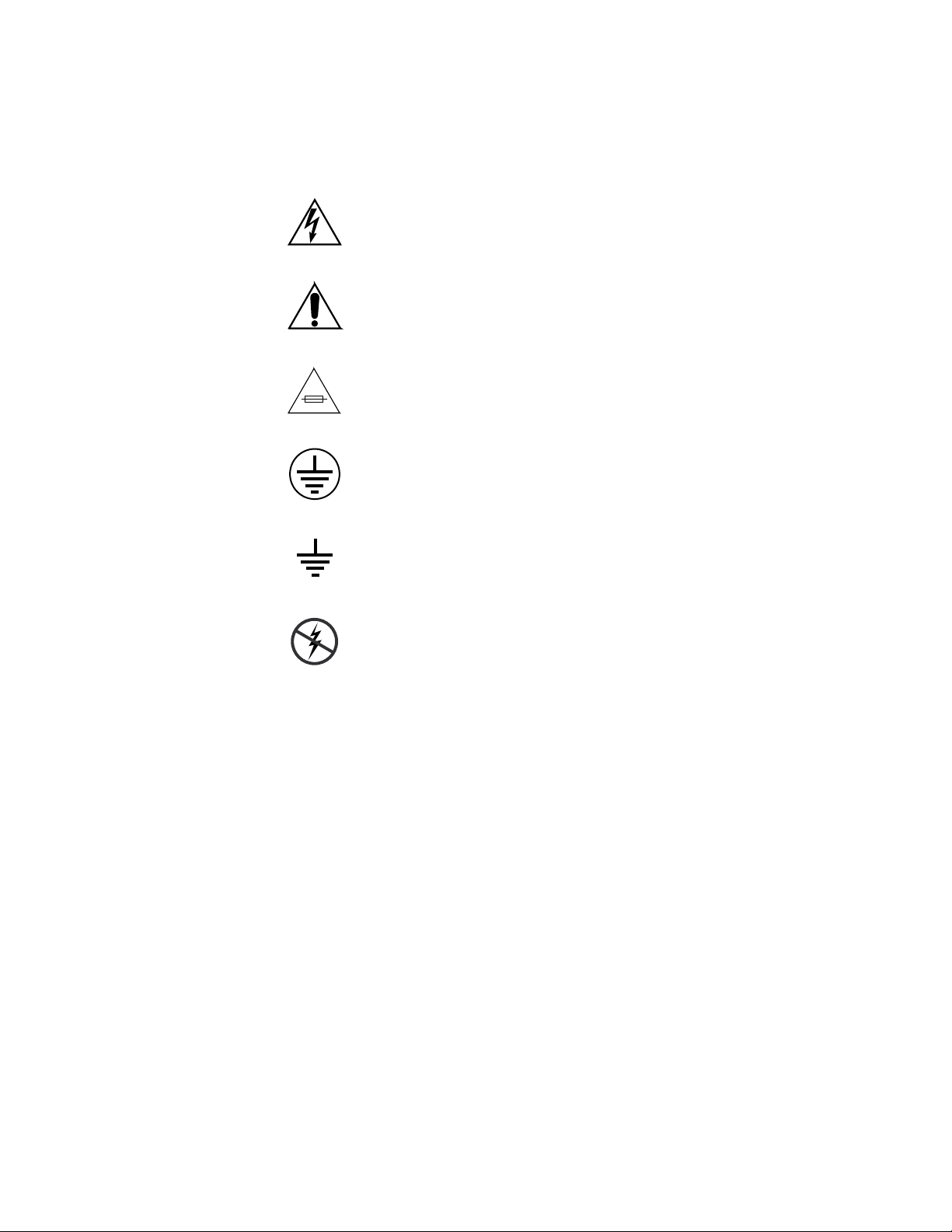
The following symbols may appear on the product:
Indicates that dangerous high voltage is present within the
equipment enclosure that may be of sufficient magnitude to
constitute a risk of electric shock.
Indicates that user, operator or service technician should
refer to product manual(s) for important operating, maintenance, or service instructions.
This is a prompt to note fuse rating when replacing fuse(s).
The fuse referenced in the text must be replaced with one
having the ratings indicated.
Warnings
Identifies a protective grounding terminal which must be
connected to earth ground prior to making any other equipment connections.
Identifies an external protective grounding terminal which
may be connected to earth ground as a supplement to an
internal grounding terminal.
Indicates that static sensitive components are present which
may be damaged by electrostatic discharge. Use anti-static
procedures, equipment and surfaces during servicing.
The following warning statements identify conditions or practices that can
result in personal injury or loss of life.
Dangerous voltage or current may be present
battery (if applicable) before removing protective panels, soldering, or
replacing components.
— Disconnect power and remove
Do not service alone
person capable of rendering first aid and resuscitation is present.
Remove jewelry
and other metallic objects.
Avoid exposed circuitry
circuitry when power is present.
x 7500 Series Instruction Manual
— Do not internally service this product unless another
— Prior to servicing, remove jewelry such as rings, watches,
— Do not touch exposed connections, components or
Page 11

Use proper power cord
— Use only the power cord supplied or specified for
this product.
Ground product
— Connect the grounding conductor of the power cord to
earth ground.
Operate only with covers and enclosure panels in place
— Do not operate this
product when covers or enclosure panels are removed.
Use correct fuse
— Use only the fuse type and rating specified for this
product.
Use only in dry environment
Use only in non-explosive environment
— Do not operate in wet or damp conditions.
— Do not operate this product in an
explosive atmosphere.
High leakage current may be present
— Earth connection of product is essential
before connecting power.
Dual power supplies may be present
— Be certain to plug each power supply
cord into a separate branch circuit employing a separate service ground.
Disconnect both power supply cords prior to servicing.
Double pole neutral fusing
— Disconnect mains power prior to servicing.
Cautions
Use proper lift points
Avoid mechanical hazards
— Do not use door latches to lift or move equipment.
— Allow all rotating devices to come to a stop before
servicing.
The following caution statements identify conditions or practices that can
result in damage to equipment or other property
Use correct power source
— Do not operate this product from a power sour ce
that applies more than the voltage specified for the product.
Use correct voltage setting
— If this product lacks auto-ranging power supplies, before applying power ensure that the each power supply is set to
match the power source.
Provide proper ventilation
— To prevent product overheating, provide equip-
ment ventilation in accordance with installation instructions.
Use anti-static procedures
— Static sensitive components are present which
may be damaged by electrostatic discharge. Use anti-static procedures,
equipment and surfaces during servicing.
7500 Series Instruction Manual xi
Page 12

Do not operate with suspected equipment failure
— If you suspect product
damage or equipment failure, have the equipment inspected by qualified
service personnel.
Ensure mains disconnect
— If mains switch is not provided, the power cor d(s)
of this equipment provide the means of disconnection. The socket outlet
must be installed near the equipment and must be easily accessible. Verify
that all mains power is disconnected before installing or removing power
supplies and/or options.
Route cable properly
— Route power cor ds and other cables so that they ar not
likely to be damaged. Properly support heavy cable bundles to avoid connector damage.
Use correct power supply cords
— Power cords for this equipment, if pr ovided,
meet all North American electrical codes. Operation of this equipment at
voltages exceeding 130 VAC requires power supply cords which comply
with NEMA configurations. International power cords, if provided, have
the approval of the country of use.
Use correct replacement battery
— This product may contain batteries. To
reduce the risk of explosion, check polarity and replace only with the same
or equivalent type recommended by manufacturer. Dispose of used batteries according to the manufacturer’s instructions.
Troubleshoot only to board level
— Circuit boards in this product are densely
populated with surface mount technology (SMT) components and application specific integrated circuits (ASICS). As a result, circuit board repair at
the component level is very difficult in the field, if not impossible. For warranty compliance, do not troubleshoot systems beyond the board level.
xii 7500 Series Instruction Manual
Page 13

Regulatory Notices
Certifications and Compliances
FCC Emission Control
This equipment has been tested and found to comply with the limits for a
Class A digital device, pursuant to Part 15 of the FCC Rules. These limits
are designed to provide reasonable pr otection against harmful interference
when the equipment is operated in a commercial environment. This equipment generates, uses, and can radiate radio frequency energy and, if not
installed and used in accordance with the instruction manual, may cause
harmful interference to radio communications. Operation of this equipment in a residential area is likely to cause harmful interference in which
case the user will be required to correct the interfer ence at his own expense.
Changes or modifications not expressly approved by Grass Valley Group
can affect emission compliance and could void the user’s authority to
operate this equipment.
Canadian EMC Notice of Compliance
This digital apparatus does not exceed the Class A limits for radio noise
emissions from digital apparatus set out in the Radio Interference Regulations of the Canadian Department of Communications.
Le présent appareil numérique n’emet pas de bruits radioélectriques
dépassant les limites applicables aux appareils numeriques de la classe A
préscrites dans le Règlement sur le brouillage radioélectrique édicte par le
ministère des Communications du Canada.
EN55022 Class A Warning
For products that comply with Class A. In a domestic environment this
product may cause radio interference in which case the user may be
required to take adequate measures.
7500 Series Instruction Manual xiii
Page 14

Canadian Certified Power Cords
Canadian approval includes the products and power cords appr opriate for
use in the North America power network. All other power cords supplied
are approved for the country of use.
Canadian Certified AC Adapter
Canadian approval includes the AC adapters appropriate for use in the
North America power network. All other AC adapters supplied are
approved for the country of use.
Laser Compliance
Laser Safety Requirements
The device used in this product is a Class 1 certified laser product. Operating this product outside specifications or altering from its original design
may result in hazardous radiation exposure, and may be consider ed an act
of modifying or new manufacturing of a laser product under U.S. regulations contained in 21CFR Chapter1, subchapter J or CENELEC regulations
in HD 482 S1. People performing such an act are required by law to recertify and reidentify this product in accordance with provisions of 21CFR
subchapter J for distribution within the U.S.A., and in accordance with
CENELEC HD 482 S1 for distribution within countries using the IEC 825
standard.
Laser Safety
Laser safety in the United States is regulated by the Center for Devices and
Radiological Health (CDRH). The laser safety regulations are published in
the “Laser Product Performance Standard,” Code of Federal Regulation
(CFR), Title 21, Subchapter J.
The international Electrotechnical Commission (IEC) Standard 825, “Radiation of Laser Products, Equipment Classification, Requirements and
User’s Guide,” governs laser products outside the United States. Europe
and member nations of the European Free trade Association fall under the
jurisdiction of the Comite European de Normalization Electrotechnique
(CENELEC).
For the CDRH: The radiant power is detected trough a 7 mm aperture at a
distance of 200 mm from the source focused through a lens with a focal
length of 100 mm.
For IEC compliance: The radiant power is detected trough a 7 mm aperture
at a distance of 100 mm from the source focused through a lens with a focal
length of 100 mm.
xiv 7500 Series Instruction Manual
Page 15

FCC Emission Limits
Certification
This device complies with Part 15 of the FCC Rules. Operation is subject to
the following two conditions: (1) This device may no cause harmful interference, and (2) this device must accept any interference received,
including interference that may cause undesirable operation. This device
has been tested and found to comply with FCC Part 15 Class B limits for a
digital device when tested with a representative laser-based fiber optical
system that complies with ANSI X3T11 Fiber Channel Standard.
Category Standard Designed/tested for compliance with:
Safety UL1419 Professional Video and Audio Equipment
7500 Series Instruction Manual xv
Page 16

xvi 7500 Series Instruction Manual
Page 17
Overview
Introduction
The 7500 Series Routing frames can be controlled by either the Series 7000
Signal Management System or the Encore Control System. The 7500 Series
Routing frames expand the multiformat routing capability of the Series
7000 Signal Management System and are compatible with existing Series
7000 matrices and control panels.
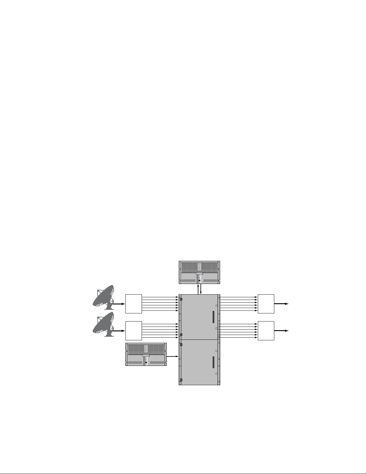
The 7500NB frame is designed to switch digital signals up to 50 Mbps.
Figure 1-1 shows an example of MPEG signal routing using a SMS-
NB512x512
Figure 1-1. 7500NB 512x512 MPEG Signal Routing
Section
1
Incoming
Satellite Feed
Incoming
Satellite Feed
PROFILE XP
Streaming Server
Multiple MPEG
Transport Streams
DMUX
DMUX
PROFILE XP
Time Delay Recorder
SMS-NB512x512
Matrix Frame
0723_00_01
MUX
MUX
Re-Transmission
via Cable or Satellite
Re-Transmission
via Cable or Satellite
7500 Series Instruction Manual 1-1
Page 18
Section 1 — Overview
Analog
Inputs
SDI Inputs
8900 Series
A-to-D Converters
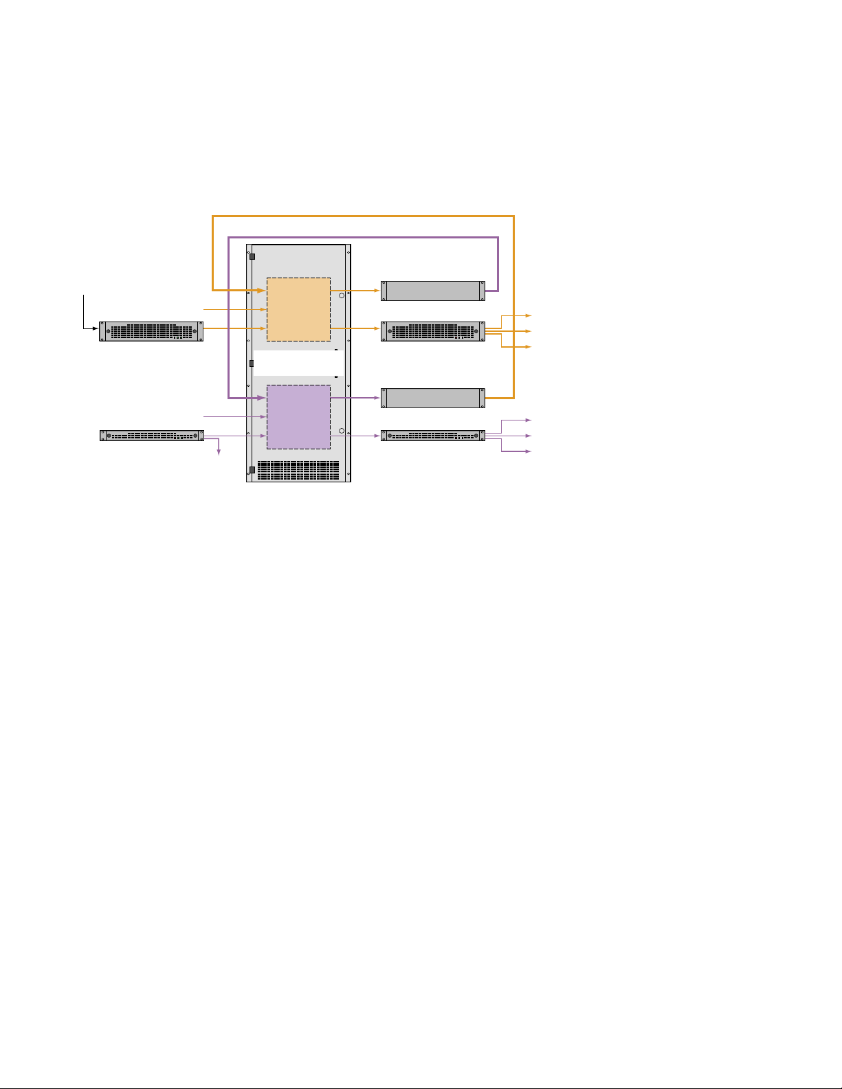
The 7500WB frame is designed to switch signals from 10 Mbps to 1.485
Gbps. Figure 1-2 shows an example of Standard Definition (SD) and High
Definition (HD) signal routing using a 7500WB 256x256.
Figure 1-2. 7500WB 256x256 HD and SD Signal Routing
SD Tie Lines
HD Tie Lines
SD
Operation
7500WB 256x256
Matrix Frame
Up Converter
8900 Series DAs
Profile® XP
Monitor
Master Control
HD Inputs
Monitor
HD
Operation
System Level Architecture
7500NB Architecture
7500NB AES Audio Systems are built around a 256x256, two bay, 12RU
matrix. The 7500NB 256x256 uses one matrix and the 7500NB 512x512 uses
two matrices connected together at the backplanes with expansion connector modules. The 7500NB 1024x1024 uses eight matrices connected
together.
Matrices are populated with crosspoint modules, input modules, output
modules, and matrix controller modules. synchronous and asynchronous
input and output modules are available. Both types of modules can be
placed in the same matrix. The synchronous modules can be configured to
allow an asynchronous signal to be passed through an input or an output.
Down Converter
0723_00_02
2000 Series DAs2000 Series DAs
Profile XP
Monitor
Master Control
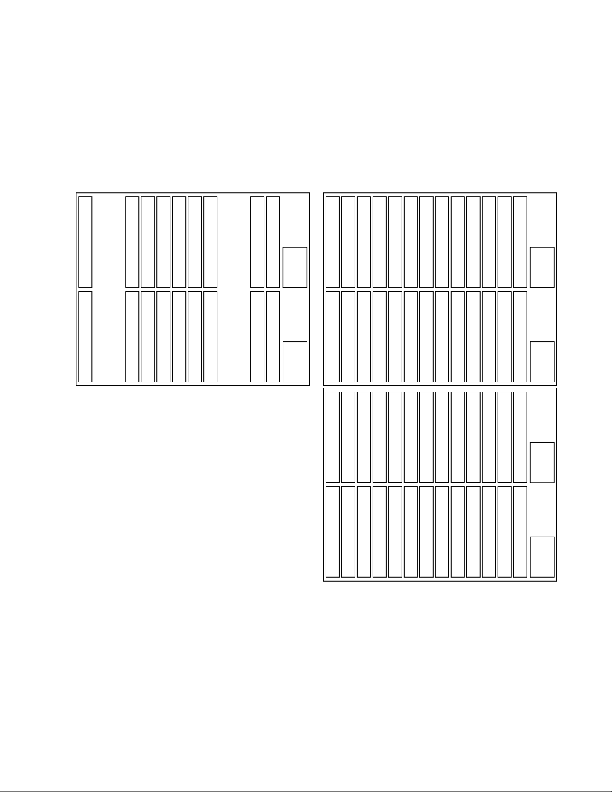
The two bay, 12RU matrix uses four input modules, four output modules,
and eight crosspoint modules for a fully configured 256x256 system. Each
bay of the system contains a slot for a matrix controller and a power supply.
The slot locations for the modules are shown in Figure 1-3. The empty slots
are used for crosspoint modules in expansion systems larger than 256x256.
1-2 7500 Series Instruction Manual
Page 19
System Level Architecture
Two of the two bay, 12RU matrices are connected using expansion connectors to create a fully configured 512x512 system. The system uses eight
input modules, eight output modules, and thirty-two crosspoint modules
as shown in Figure 1-3. The top bay is always used for inputs 1-128, the
second one for inputs 129-256, the third for 255-384, and the fourth bay is
used for inputs 385-512.
Figure 1-3. 7500NB Module Placement
7500NB 256x256
Inputs 1-64
Inputs 129-192
Xpt Expansion Slot
Xpt Expansion Slot
Xpt Expansion Slot
Xpt Expansion Slot
Outputs 1-64
Xpt (In=1-128, Out=1-64)
Xpt (In=129-256, Out=1-64)
Xpt (In=1-128, Out=129-192)
Outputs 129-192
Xpt (In=129-256, Out=129-192)
Outputs 65-128
Xpt (In=1-128, Out=193-256)
Xpt (In=129-256, Out=193-256)
Xpt (In=1-128, Out=65-128)
Outputs 193-256
Xpt (In=129-256, Out=65-128)
Inputs 65-128
Xpt Expansion Slot
Xpt Expansion Slot
Xpt Expansion Slot
Xpt Expansion Slot
Matrix Controller 1
Inputs 193-256
Matrix Controller 2
Power
Supply
1
Power
Supply
2
7500NB 512x512
Inputs 1-64
Xpt (In=1-128, Out=257-320)
Inputs 129-192
Xpt (In=129-256, Out=257-320)
Inputs 257-320
Xpt (In=257-384, Out=1-64)
Xpt (In=1-128, Out=1-64)
Xpt (In=1-128, Out=385-448)
Xpt (In=129-256, Out=1-64)
Xpt (In=129-256, Out=385-448)
Xpt (In=257-384, Out=129-192)
Xpt (In=257-384, Out=257-320)
Outputs 1-64
Xpt (In=1-128, Out=129-192)
Outputs 129-192
Xpt (In=129-256, Out=129-192)
Outputs 257-320
Xpt (In=257-384, Out=385-448)
Outputs 65-128
Xpt (In=1-128, Out=193-256)
Xpt (In=129-256, Out=193-256)
Xpt (In=257-384, Out=449-512)
Xpt (In=1-128, Out=65-128)
Outputs 193-256
Xpt (In=129-256, Out=65-128)
Outputs 321-384
Xpt (In=257-384, Out=321-384)
Inputs 65-128
Power
Matrix Controller 1
Xpt (In=1-128, Out=449-512)
Xpt (In=1-128, Out=321-384)
Xpt (In=129-256, Out=449-512)
Xpt (In=129-256, Out=321-384)
Xpt (In=257-384, Out=65-128)
Xpt (In=257-384, Out=193-256)
Supply
1
Inputs 193-256
Power
Matrix Controller 2
Supply
2
Inputs 321-384
Power
Matrix Controller 3
Supply
3
Inputs 385-448
Xpt (In=385-512, Out=1-64)
Xpt (In=385-512, Out=129-192)
Outputs 385-448
Xpt (In=385-512, Out=257-320)
Outputs 449-512
Xpt (In=385-512, Out=385-448)
Xpt (In=385-512, Out=449-512)
Xpt (In=385-512, Out=321-384)
Xpt (In=385-512, Out=193-256)
Inputs 449-512
Power
Matrix Controller 4
Xpt (In=385-512, Out=65-128)
Supply
4
7500 Series Instruction Manual 1-3
Page 20
Section 1 — Overview
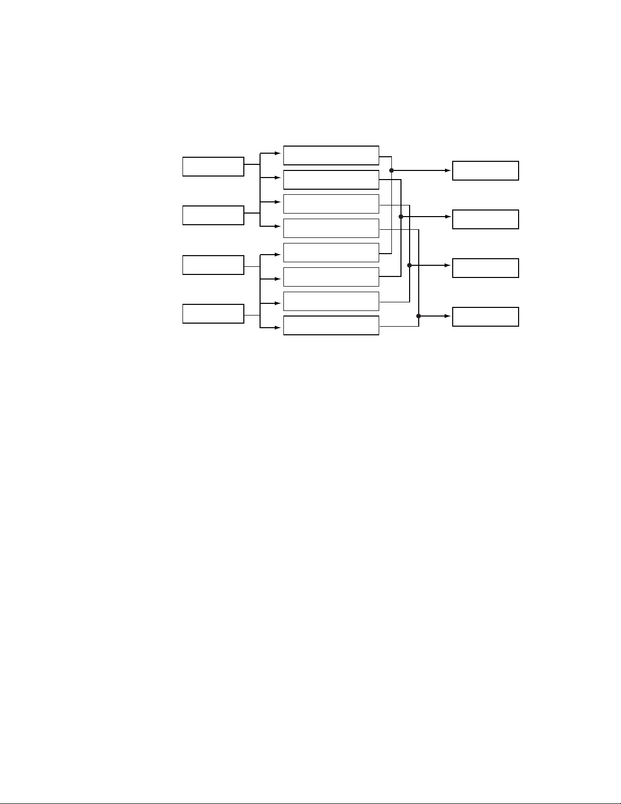
Inputs are routed by the Crosspoint modules to the Output modules to
ensure that all Inputs are available to all Outputs. See Figure 1-4 for the
256x256 signal flow and Figure 1-5 for the 512x512 signal flow.
Figure 1-4. 7500NB 256x256 Signal Flow
Xpt (In=1-128, Out=1-64)
Inputs 1-64
Xpt (In=1-128, Out=65-128)
Xpt (In=1-128, Out=129-192)
Inputs 65-128
Xpt (In=1-128, Out=193-256)
Xpt (In=129-256, Out=1-64)
Inputs 129-192
Xpt (In=129-256, Out=65-128)
Outputs 1-64
Outputs 65-128
Outputs 129-192
Inputs 193-256
Xpt (In=129-256, Out=129-192)
Outputs 193-256
Xpt (In=129-256, Out=193-256)
1-4 7500 Series Instruction Manual
Page 21
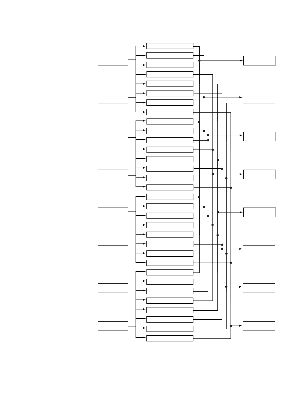
Figure 1-5. 7500NB 512x512Signal Flow
Xpt (In=1-128, Out=1-64)
Xpt (In=1-128, Out=65-128)
Inputs 1-64
Inputs 65-128
Inputs 129-192
Xpt (In=1-128, Out=129-192)
Xpt (In=1-128, Out=193-256)
Xpt (In=1-128, Out=257-320)
Xpt (In=1-128, Out=321-384)
Xpt (In=1-128, Out=385-448)
Xpt (In=1-128, Out=449-512)
Xpt (In=129-256, Out=1-64)
Xpt (In=129-256, Out=65-128)
Xpt (In=129-256, Out=129-192)
System Level Architecture
Outputs 1-64
Outputs 65-128
Outputs 129-192
Inputs 193-256
Inputs 257-320
Inputs 321-384
Inputs 385-448
Xpt (In=129-256, Out=193-256)
Xpt (In=129-256, Out=257-320)
Xpt (In=129-256, Out=321-384)
Xpt (In=129-256, Out=385-448)
Xpt (In=129-256, Out=449-512)
Xpt (In=257-384, Out=1-64)
Xpt (In=257-384, Out=65-128)
Xpt (In=257-384, Out=129-192)
Xpt (In=257-384, Out=193-256)
Xpt (In=257-384, Out=257-320)
Xpt (In=257-384, Out=321-384)
Xpt (In=257-384, Out=385-448)
Xpt (In=257-384, Out=449-512)
Xpt (In=385-512, Out=1-64)
Xpt (In=385-512, Out=65-128)
Xpt (In=385-512, Out=129-192)
Outputs 193-256
Outputs 257-320
Outputs 321-384
Outputs 385-448
Xpt (In=385-512, Out=193-256)
Xpt (In=385-512, Out=257-320)
Xpt (In=385-512, Out=321-384)
Inputs 449-512
Xpt (In=385-512, Out=385-448)
Xpt (In=385-512, Out=449-512)
Outputs 449-512
7500 Series Instruction Manual 1-5
Page 22
Section 1 — Overview
64 128 192 256 320 384 448 512 576 640 704 768 832 896 960 1024
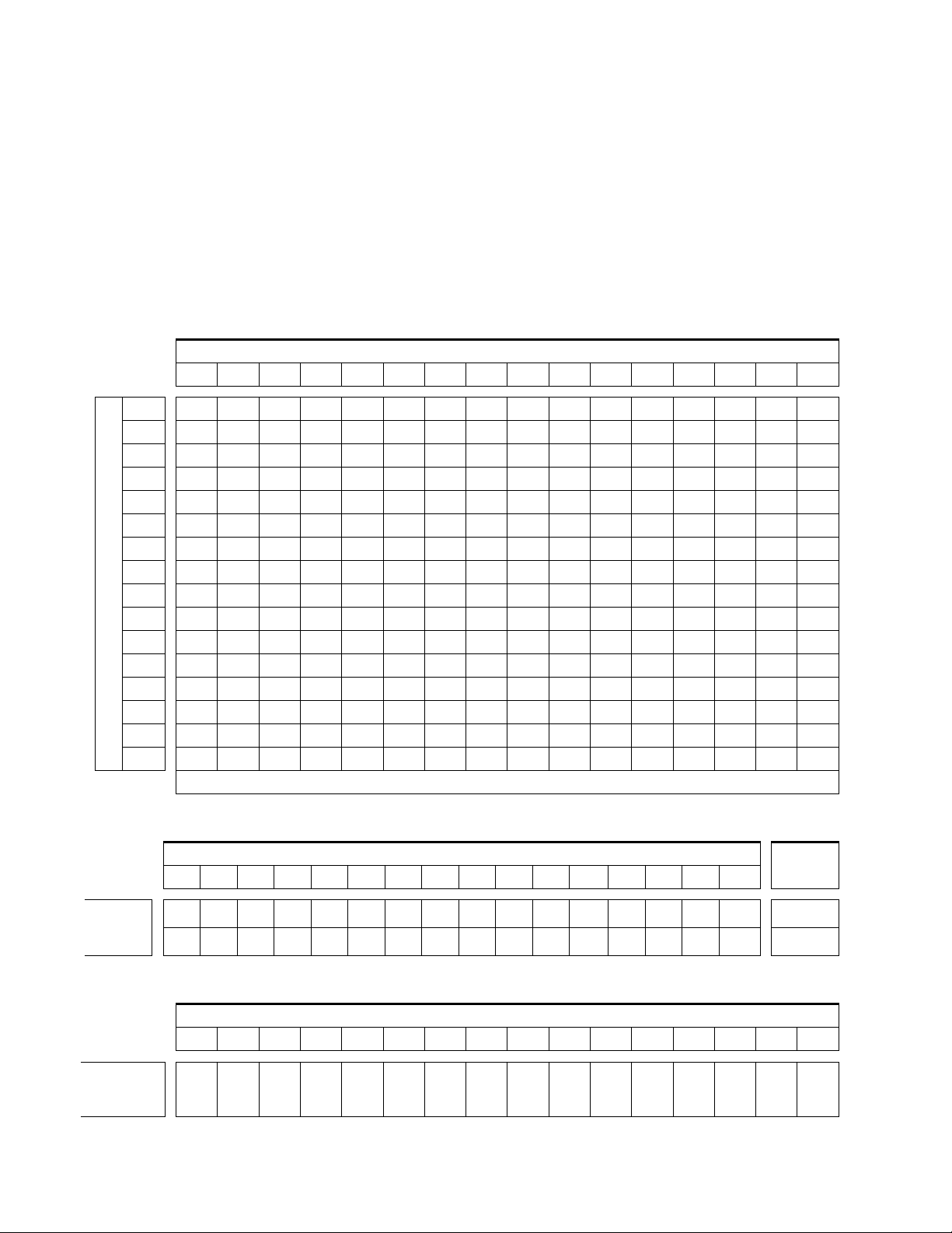
7500NB systems can be expanded in increments of 64 inputs/outputs to as
large as 1024x1024. They are assembled using standard Grass Valley router
frames, distribution amplifiers, Ethernet switches, and in some cases
custom cables. Contact Customer Service for specifications and ordering
details. Table 1-1 shows the number of crosspoint modules required to
create configurations up to 1024x1024.Table 1-2 and Table 1-3 shows the
number of input and output modules needed to create configurations up to
1024x1024.The number of input modules needed is affected by how many
outputs the system contains.
Table 1-1. Required AES 128x64 Crosspoint Modules
Outputs
128
192
256
320
384
448
512
576
Inputs
640
704
768
832
896
960
1024
64
12345678910111213141516
12345678910111213141516
2468101214161820222426283032
2468101214161820222426283032
3691215 18 21 24 27 30 33 36 39 42 45 48
3691215 18 21 24 27 30 33 36 39 42 45 48
481216 20 24 28 32 36 40 44 48 52 56 60 64
481216 20 24 28 32 36 40 44 48 52 56 60 64
5101520253035404550556065707580
5101520253035404550556065707580
6121824303642485460667278849096
6121824303642485460667278849096
714212835424956607077849198105112
714212835424956607077849198105112
81624324048566466808896104112120128
81624324048566466808896104112120128
Crosspoint Modules Required
Table 1-2. Required AES Input Modules
Inputs
64 128 192 256 320 384 448 512 576 640 704 768 832 896 960 1024
Outputs
# of Input
Boards
Required
# of Output
Boards
Required
12345678910111213141516
2468101214161820222426283032 >512
Table 1-3. Required AES Output Modules
Outputs
64 128 192 256 320 384 448 512 576 640 704 768 832 896 960 1024
12345678910111213141516
≤
512
1-6 7500 Series Instruction Manual
Page 23
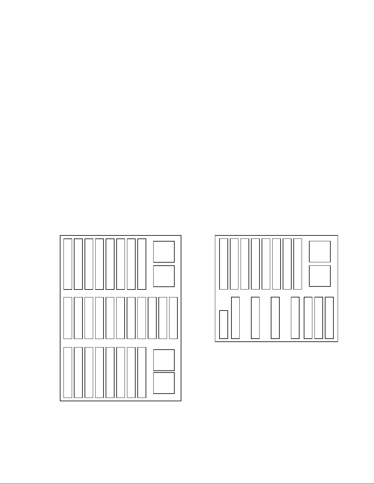
7500WB Architecture
The 7500WB 256x256 matrix frame is configured with a Controller module,
two Power Supply modules, eight Input modules, eight Crosspoint modules, eight Output modules, a two-piece backplane, an interconnect and an
optional monitor module. The router has two Controller module slots and
four Power Supply module slots to allow for redundancy. See Figure 1-6.
The 7500WB 128x128 matrix frame is configured with a Controller module,
one Power Supply module, four Input modules, four Crosspoint modules,
four Output modules, a backplane, an interconnect, a DC Distribution
module, and an optional monitor module. The router has two Controller
module slots and two Power Supply module slots to allow for redundancy.
See Figure 1-6.
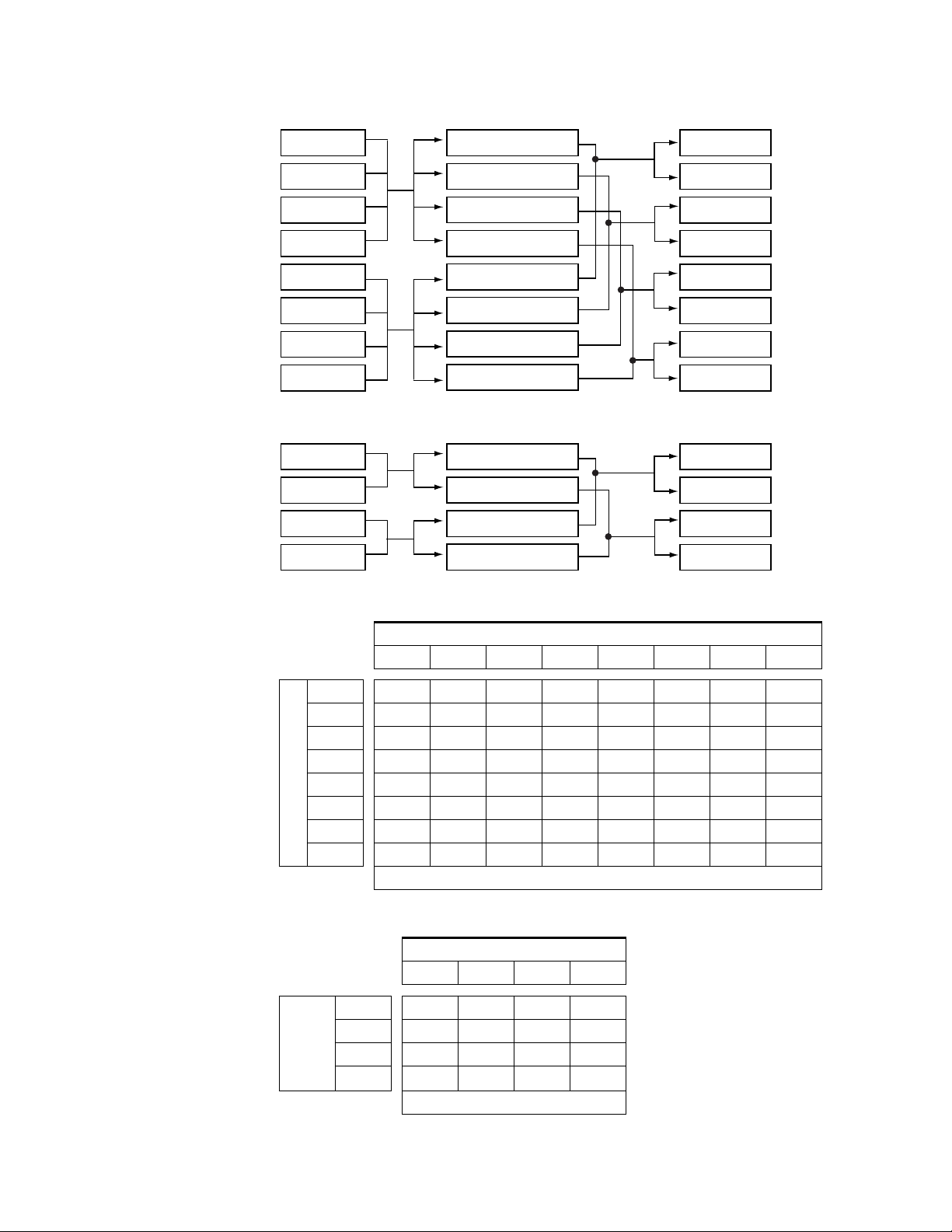
Inputs are routed by the Crosspoint modules to the Output modules to
ensure that all Inputs are available to all Outputs. See Figure 1-7 and
Figure 1-8 for the signal flow. Table 1-4 shows how many Crosspoint,
Input, and Output modules are needed to create configurations in a
7500WB 256x256 from 32x32 to 256x256. Table 1-5 shows how many Cros-
spoint, Input, and Output modules are needed in a 7500WB 128x128 to
create configurations from 32x32 to 128x128.
System Level Architecture
7500WB 256x256
Input 1-32
Input 65-96
Output 1-32
Xpt (In=1-128, Out=1-64)
Xpt (In=1-128, Out=65-128)
Xpt (In=1-128, Out=129-192)
Input 33-64
Input 97-128
Output 33-64
Figure 1-6. 7500WB Module Placement
Output 65-96
Output 129-160
Xpt (In=129-256, Out=1-64)
Xpt (In=1-128, Out=193-256)
Output 97-128
Output 161-192
Input 129-160
Output 193-224
Xpt (In=129-256, Out=65-128)
Xpt (In=129-256, Out=129-192)
Input 161-192
Output 225-256
Power
Supply
1
Power
Input 193-224
Supply
2
Monitor
Controller
Controller
Xpt (In=129-256, Out=193-256)
Power
Supply
3
Power
Input 225-256
Supply
4
7500WB 128x128
Input 1-32
Input 33-64
Output 1-32
Xpt (In=1-64, Out=1-64)
DC Distribution
Output 33-64
Output 65-96
Xpt (In=1-64, Out=65-128)
Input 65-96
Output 97-128
Xpt (In=65-128, Out=1-64)
Power
Supply
1
Power
Input 97-128
Supply
2
Monitor
Controller
Controller
Xpt (In=65-128, Out=65-128)
7500 Series Instruction Manual 1-7
Page 24
Section 1 — Overview
Figure 1-7. Signal Flow 7500WB 256x256
Inputs 1-32
Xpt (In=1-128, Out=1-64)
Outputs 1-32
Inputs 33-64
Inputs 65-96
Inputs 97-128
Inputs 129-160
Inputs 161-192
Inputs 193-224
Inputs 225-256
Xpt (In=1-128, Out=65-128)
Xpt (In=1-128, Out=129-192)
Xpt (In=1-128, Out=193-256)
Xpt (In=129-256, Out=1-64)
Xpt (In=129-256, Out=65-128)
Xpt (In=129-256, Out=129-192)
Xpt (In=129-256, Out=193-256)
Figure 1-8. Signal Flow 7500WB 128x128
Inputs 1-32
Inputs 33-64
Inputs 65-96
Inputs 97-128
Xpt (In=1-64, Out=1-64)
Xpt (In=1-64, Out=65-128)
Xpt (In=65-128, Out=1-64)
Xpt (In=65-128, Out=65-128)
Table 1-4. Crosspoint Modules Required for 7500WB 256x256
Outputs 33-64
Outputs 65-96
Outputs 97-128
Outputs 129-160
Outputs 161-192
Outputs 193-224
Outputs 224-256
Outputs 1-32
Outputs 33-64
Outputs 65-96
Outputs 97-128
Outputs (# of Modules)
32 (1) 64 (2) 96 (3) 128 (4) 160 (5) 196 (6) 224 (7) 256 (8)
32 (1)
64 (2)
96 (3)
128 (4)
160 (5)
196 (6)
Inputs (# of Modules)
224 (7)
256 (8)
11223344
11223344
11223344
11223344
22446688
22446688
22446688
22446688
Crosspoint Modules Required
Table 1-5. Crosspoint Modules Required for 7500WB 128x128
Outputs (# of Modules)
32 (1) 64 (2) 96 (3) 128 (4)
32 (1)
64 (2)
96 (3)
Inputs
128 (4)
(# of Modules)
1122
1122
2244
2244
Crosspoint Modules Required
1-8 7500 Series Instruction Manual
Page 25
Installation
Frame Installation
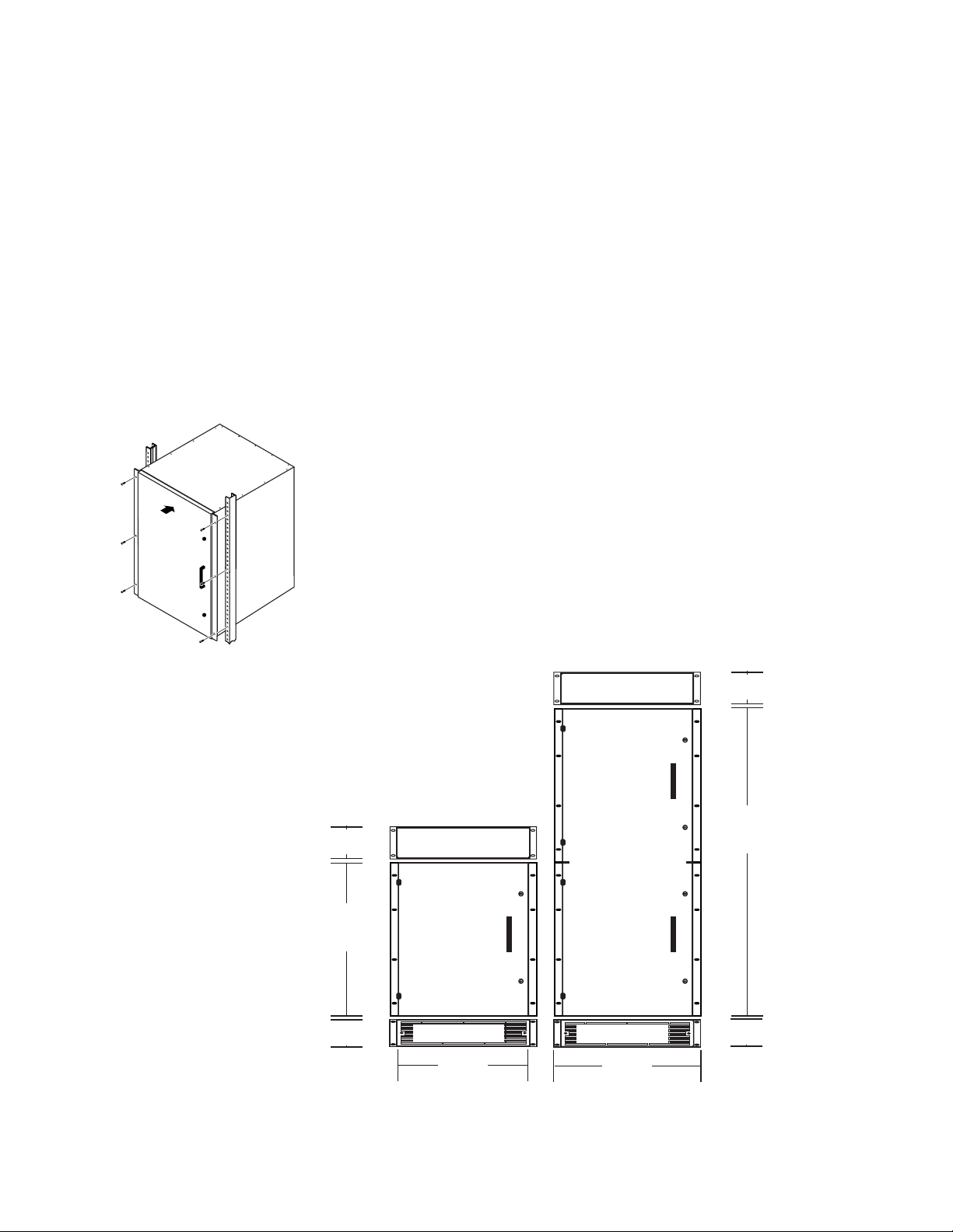
The 7500 Series matrices are installed in a standard 483 mm (19-inch) rack.
Rear frame support is not required.
7500 NB Frame Installation
The 7500NB 256x256 occupies 12 rack-units. Cooling is by vertical airflow
using an external fan set. The 7500NB 512x512 is two 7500NB 256x256
frames connected by an Expansion module set. The 7500NB 512x512 occupies 24 rack-units. See Figure 2-2.
Section
2
Figure 2-1. Rack Mount
Figure 2-2. NB Rack Installation Front View
2 RU
89 mm/3.55 in.
12 RU
534 mm
21 in.
2 RU
89 mm/3.55 in.
Exhaust Unit
7500NB 256x256
Frame
Intake/Fan Unit
438 mm
17.25 in.
Exhaust Unit
7500NB 512x512
Frame
Intake/Fan Unit
483 mm
19 in.
2 RU
89 mm/3.55 in.
24 RU
1067 mm
42 in.
2 RU
89 mm/3.55 in.
7500 Series Instruction Manual 2-1
Page 26
Section 2 — Installation
7500 WB Frame Installation
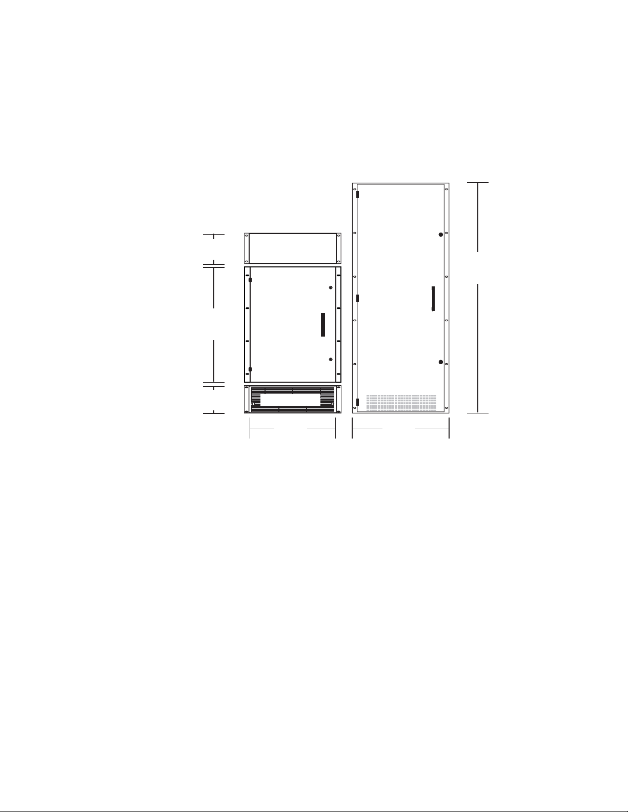
The 7500WB 256x256 router occupies 25 rack-units. Cooling is by vertical
airflow using a fan mounted inside the top of the frame and an air filter on
the front door . The 7500WB 128x128 r outer occupies 13 rack-units. Cooling
is by vertical airflow using an external fan set. See Figure 2-3.
Figure 2-3. WB Rack Installation Front View
7500WB 256x256
Frame
3 RU
134 mm/5.25 in.
13 RU
578 mm
22.72 in.
Exhaust Unit
25 RU
1110 mm
43.75 in.
7500WB 128x128
Frame
3 RU
134 mm/5.25 in.
Intake/Fan Unit
438 mm
17.25 in.
483 mm
19 in.
2-2 7500 Series Instruction Manual
Page 27
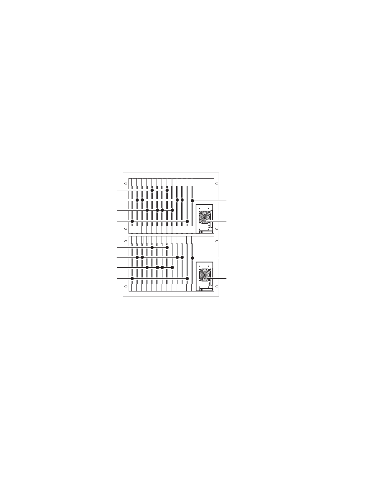
Module Installation
All the modules are vertically oriented in the frames, and edge guides aid
insertion and removal.
CAUTION It is critical that the modules be placed in the proper slot and oriented cor-
7500NB Module Placement
7500NB modules are oriented in the frame with the front (populated) side
facing to the right. See Figure 2-4.
Figure 2-4. 7500NB Module Configuration and Alignment
Output Modules
Crosspoint Expansion Modules
Crosspoint Modules
Input Modules
rectly to prevent bent pins.
DC OK
AC PRESENT
Module Installation
Controller Modules
Power Supply Modules
Output Modules
Crosspoint Expansion Modules
Crosspoint Modules
Input Modules
AC PRESENT
Controller Modules
DC OK
Power Supply Modules
7500 Series Instruction Manual 2-3
Page 28
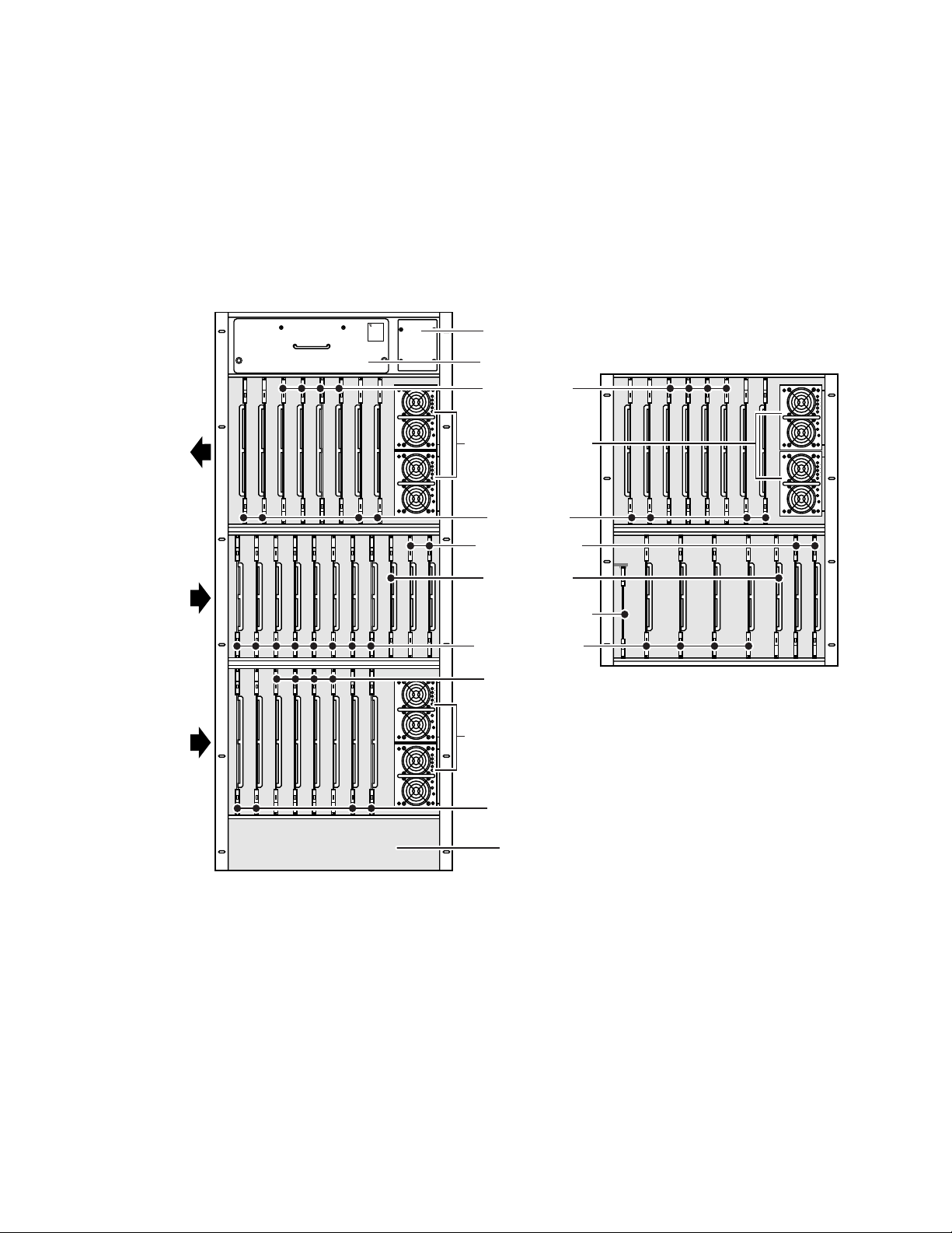
Section 2 — Installation
7500WB Module Placement
7500WB 256X256
In the top row of the 7500WB, Input and Output modules are oriented in
the frame with the front (populated) side facing to the left. The other rows
of modules are orientated in the frame with the front (populated) side
facing to the right. See Figure 2-5.
Figure 2-5. 7500WB Module Configuration and Alignment
WARNING
ROTATING
FAN BLADES
PULL OUT
1/2 INCH
AND WAIT
30 SECONDS
BEFORE
REMOVING
Thermal Control
Module Cover
Exhaust Fan Unit
7500WB 128X128
In this row all
Input and Output
modules are
orientated with
fronts to the left.
In this row all
modules are
orientated with
fronts to the right
In this row all
Input and Output
modules are
orientated with
fronts to the right.
All Power Supply
modules are
orientated with the
tops to the left.
100%
20 40 60 80
DCG
ACG
VADJ
100%
20 40 60 80
DCG
ACG
VADJ
Output Modules
Power Supply Modules
Input Modules
Controller Modules
Monitor Module
DC Distribution Module
Crosspoint Modules
100%
20 40 60 80
DCG
ACG
VADJ
100%
20 40 60 80
DCG
ACG
VADJ
Output Modules
Power Supply Modules
Input Modules
Air Intake
100%
20 40 60 80
DCG
ACG
VADJ
100%
20 40 60 80
DCG
ACG
VADJ
0528_01_16
2-4 7500 Series Instruction Manual
Page 29

Cabling
Cabling
Table 2-1 contains a compilation of the connectors and label variations
found on 7500 matrices. The Gender column indicates the gender of the
connector found on the 7500 matrix. The Details column contains information to assist in using the connector.
Table 2-1. Connectors Found on 7500 Matrices
Label NB WB
AES REF 1 and AES REF 2 √ - BNC Female Synchronous audio references use unbalanced 75 Ohm connector, terminator, and
ALARM - √ D-9 Pin Female Audio Alarm use serial/machine cable.
CONSOLE 1 and CONSOLE 2 √√D-9 Pin Female Terminal interface (factory use) use serial/machine cable.
DC PWR √ -Terminal
- √ Wire - Use 6 AWG (13.30 mm
DIGITAL VIDEO REF
MC1(1), MC1(2), MC2(1),
and MC2(2)
ETHERNET CONT 1 and
ETHERNET CONT 2
MC1 ETHERNET CONT 1,
MC2 ETHERNET CONT 1,
MC1 ETHERNET CONT 2,
and MC2 ETHERNET CONT 2
EXT-COM2 √√D-9 Pin Female External Control (factory use) use serial/machine cable.
FAN DC/ALARM √√Terminal
GSC √√BNC Female Global Serial Channel Interface use unbalanced 75 Ohm connector, terminator,
INPUTS √√BNC Female Use unbalanced 75 Ohm connector and coaxial cable.
MC1 EXT-COM1 and
MC2 EXT-COM1
MON 1, MON 2, MON 3,
MON 4, MON 5, MON 6,
MON 7, and MON 8
MONITOR 1-8 √ - D-25 Pin Female Monitor input use balanced 110 Ohm connector and shielded twisted pair cable
MONITOR IN - √ BNC Female Monitor input use an unbalanced 75 Ohm connector and coaxial cable.
MONITOR OUT 1, 2, 3, and 4 - √ BNC Female Monitor output use an unbalanced 75 Ohm connector and coaxial cable.
OPTION √√D-25 Pin Female Optional Interface use serial/machine cable.
OUTPUTS √√BNC Female Use unbalanced 75 Ohm connector and coaxial cable.
SMTE/LTC √√D-9 Pin Female SMPTE Line Time Code use serial/machine cable.
VID REF √ - BNC Female Video reference use unbalanced 75 Ohm connector, terminator, and coaxial cable.
VIDEO REF 1 and 2 - √ BNC Female Video reference use unbalanced 75 Ohm connector, terminator , and coaxial cable.
- √ BNC Female Future use for digital video references use unbalanced 75 Ohm connector, termi-
√ - RJ45 Female Ethernet network communication interface is 10Base-T and 100Base-T compatible
- √
√ - D-50 Pin Female Use balanced 110 Ohm connector and shielded twisted pair cable.
√√D-9 Pin Female External Control (factory use) use serial/machine cable.
√ - BNC Female Monitor output use unbalanced 75 Ohm connector and coaxial cable.
√ - D-50 Pin Female Use balanced 110 Ohm connector and shielded twisted pair cable.
Connector
Type Gender
Male Use 12 AWG (3.31 mm
Block
Male DC Fan and/or Audio Alarm use 12 AWG (3.31 mm2) wire and a 10-pin terminal
Block
Details
coaxial cable. Loop-thru cabling supported.
2
DC power connection.
nator, and coaxial cable. Loop-thru cabling supported.
use category 5 cable, 8 conductor twisted pair. All Ethernet connections need to be
routed through switches.
block connector
and coaxial cable. Loop-thru cabling supported.
Loop-thru cabling supported.
Loop-thru cabling supported.
) wire and a 3-pin terminal block connector to establish a
2
) wire to establish a DC power connection.
7500 Series Instruction Manual 2-5
Page 30
Section 2 — Installation
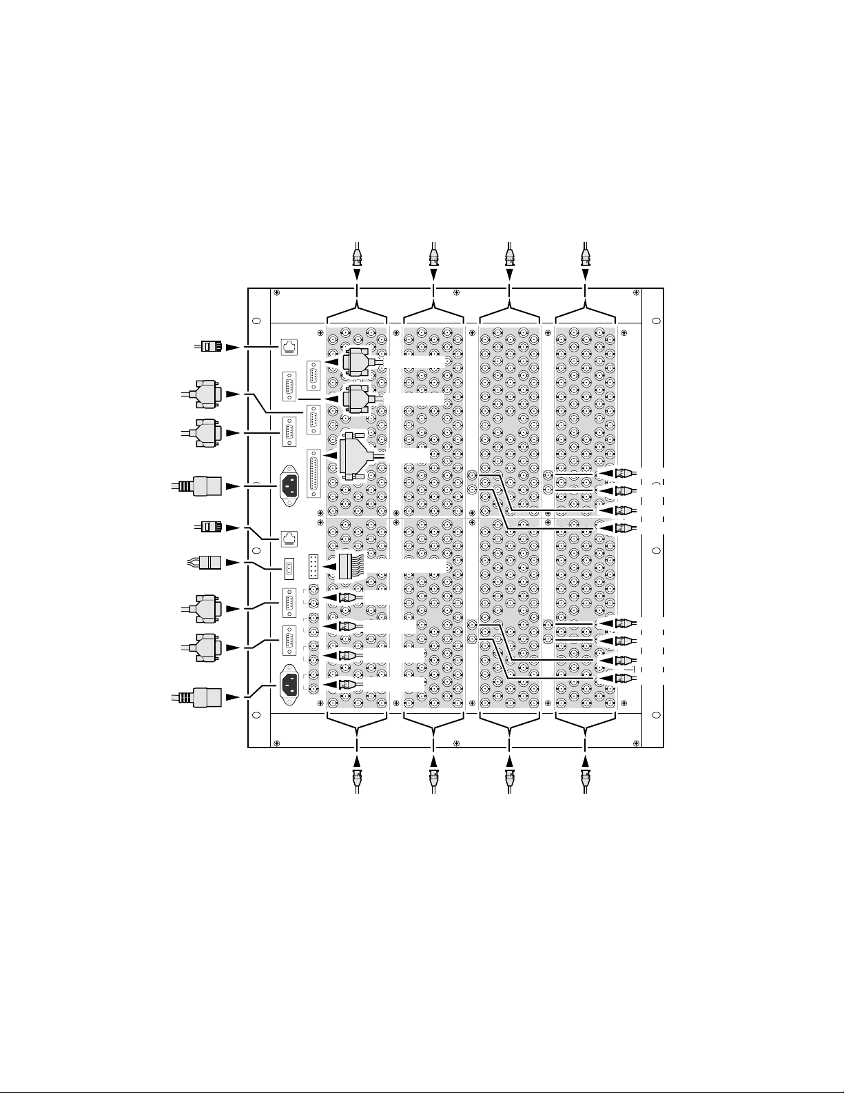
7500NB Backplane Cabling
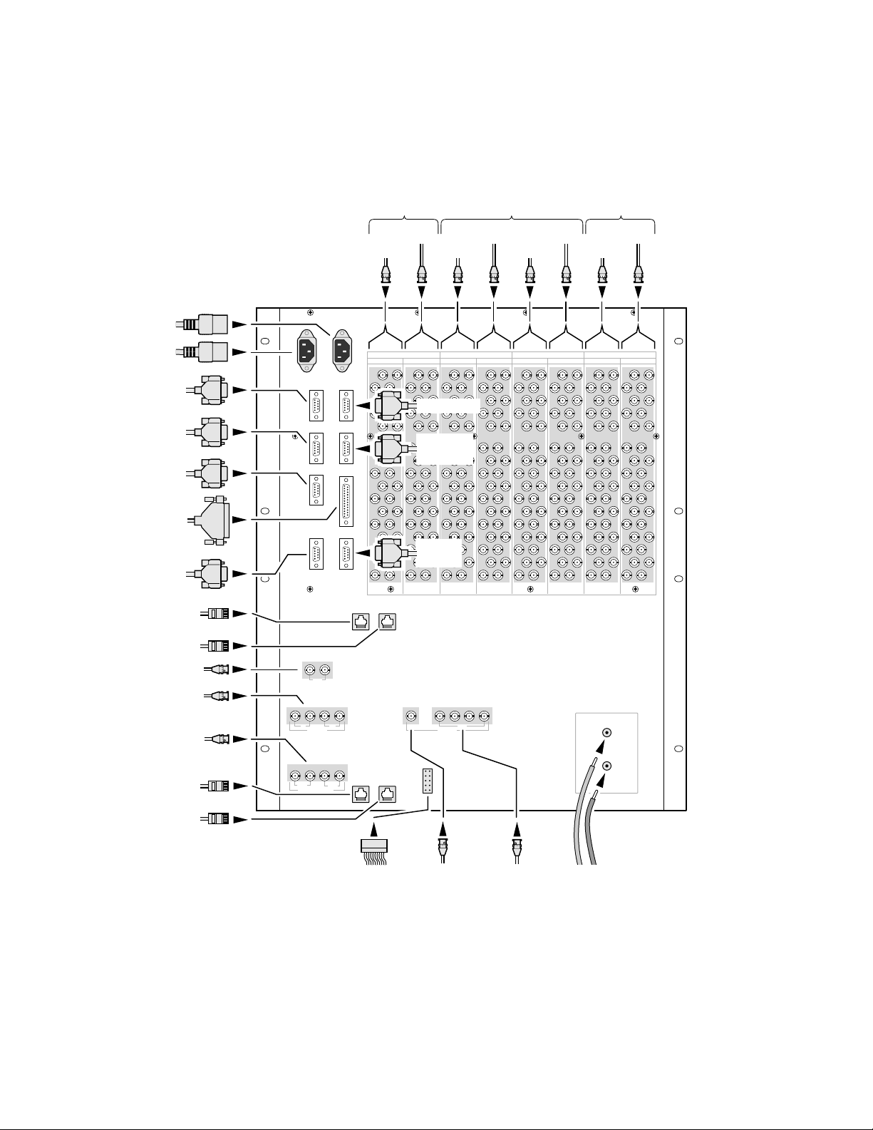
See Figure 2-6 for the 7500NB 256x256 with a BNC backplane and
Figure 2-7 for the 7500NB 256x256 with a D-50 pin connector backplane.
Figure 2-6. 7500NB Backplane Cabling with BNC Input and Output Connectors
ETHERNET
CONT 1
MC2
EXT-COM1
MC1
EXT-COM1
AC
PWR 1
ETHERNET
CONT 2
DC PWR
EXT-COM2
SMPTE/
LTC
AC
PWR 2
7500NB 256X256
GSC
VID
REF
AES
REF1
AES
REF2
Inputs
65-128
FAN DC/ALARM
GSC
VID REF
AES REF1
AES REF2
Outputs
65-128
CONSOLE 2
CONSOLE 1
OPTION
Outputs
1-64
Inputs
1-64
MON 1
MON 2
MON 3
MON 4
MON 5
MON 6
MON 7
MON 8
0723_00_4_r0
Inputs
193-256
Outputs
193-256
Outputs
129-192
Inputs
129-192
2-6 7500 Series Instruction Manual
Page 31
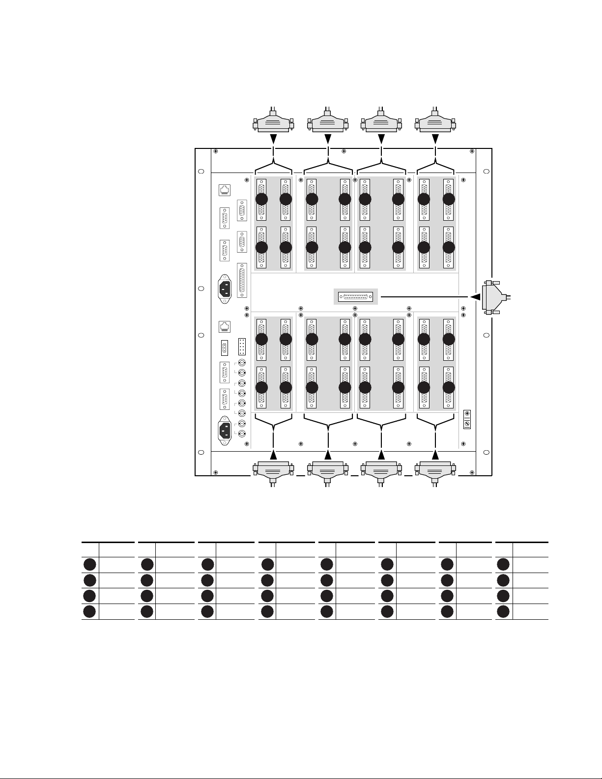
Figure 2-7. 7500NB Backplane Cabling with D-50 Pin Input and Output Connectors
Cabling
7500NB 256X256
(D-50 pin connector
version)
Note:
Refer to
Figure 2-6 for
other cabling.
Inputs
65-128
INPUTS
65-128
81
65
T
T
H
H
R
R
O
O
U
U
G
G
H
H
96
80
113
97
T
T
H
H
R
R
O
O
U
U
G
G
H
H
128
112
INPUTS
193-256
193
209
T
T
H
H
R
R
O
O
U
U
G
G
H
H
208
224
GSC
VID
REF
AES
REF1
225
241
T
T
H
H
R
R
O
O
U
U
G
G
H
H
240
256
Outputs
65-128
OUTPUTS
65-128
65
T
H
R
O
U
G
H
80
97
T
H
R
O
U
G
H
112
OUTPUTS
193-256
193
T
H
R
O
U
G
H
208
225
T
H
R
O
U
G
H
240
81
T
H
R
O
U
G
H
96
113
T
H
R
O
U
G
H
128
209
T
H
R
O
U
G
H
224
241
T
H
R
O
U
G
H
256
Outputs
1-64
OUTPUTS
1-64
1
T
H
R
O
U
G
H
16
33
T
H
R
O
U
G
H
48
OUTPUTS
129-192
129
T
H
R
O
U
G
H
144
161
T
H
R
O
U
G
H
176
Inputs
1-64
INPUTS
1-64
17
T
H
R
O
U
G
H
32
49
T
H
R
O
U
G
H
64
145
T
H
R
O
U
G
H
160
177
T
H
R
O
U
G
H
192
1
T
H
R
O
U
G
H
16
33
T
H
R
O
U
G
H
48
INPUTS
129-192
129
T
H
R
O
U
G
H
144
161
T
H
R
O
U
G
H
176
17
T
H
R
O
87654321
U
G
H
32
49
T
H
R
O
161514131211109
U
G
H
64
Monitor 1-8
145
T
H
R
O
2423222120191817
U
G
H
160
177
T
H
R
O
3231302928272625
U
G
H
192
AES
REF2
0723_00_5_r0
Inputs
193-256
Outputs
193-256
Outputs
129-192
Inputs
129-192
Table 2-2. Input and Output Groups for 7500NB with D-50 Pin Connectors
# Inputs # Inputs # Outputs # Outputs # Outputs # Outputs # Inputs # Inputs
65-80 81-96 65-80 81-96 1-16 17-32 1-16 17-32
1 2 3 4
97-112 113-128 97-112 113-128 33-48 49-64 33-48 49-64
9 10 11 12 13 14 15 16
193-256 209-224 193-256 209-224 129-144 145-160 129-144 45-160
17 18 19 20 21 22 23 24
225-240 241-256 225-240 241-256 161-176 177-192 161-176 I77-192
25 26 27 28 29 30 31
5 6 7 8
32
1
7500 Series Instruction Manual 2-7
Page 32
Section 2 — Installation
7500NB Backplane Cabling
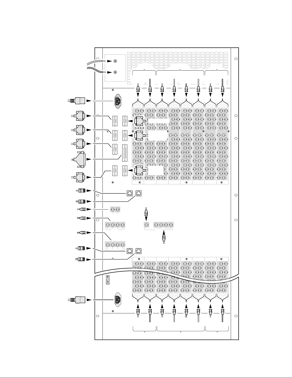
Figure 2-8 for the 7500WB 128x128, and Figure 2-9 for the 7500WB 256x256.
Figure 2-8. 7500WB 128x128 Backplane Cabling
Inputs Inputs
Outputs
AC PWR 2
AC PWR 1
CONSOLE 1
MC1
EXT-COM1
EXT-COM2
OPTION
ALARM
MC1 ETHERNET
CONT 1
MC1 ETHERNET
CONT 2
GSC
VIDEO REF
1 & 2
DIGITAL VIDEO REF
MC1(1), MC1(2),
MC2(1), & MC2(2)
MC2 ETHERNET
CONT 1
MC2 ETHERNET
CONT 2
7500WB 128X128
GSC
1
2
1 2 1 2
MC1
MC2
DIGITAL VIDEO REF
65-96
97-128
INPUTS INPUTSOUTPUTS OUTPUTS
193-224 129-160 193-224 129-160 65-96 1-32 65-96 1-32
97-128
65-96
33-64
1-32
33-64
CONSOLE 2
MC2
EXT-COM1
SMPTE/
LTC
1 2 3 4
IN
OUT
MONITORVIDEO REF
1-32
+
_
0723_00_6_r0
FAN
DC/ALARM
MONITOR
IN
MONITOR OUT
1, 2, 3, 4
48V DC
Power
2-8 7500 Series Instruction Manual
Page 33
48V DC
Power
Figure 2-9. 7500WB 256x256 Backplane Cabling
7500WB 256X256
+
_
Inputs Inputs
129-160
193-224
193-224
Outputs
129-160
65-96
1-32
Cabling
1-32
65-96
AC PWR 1
CONSOLE 1
MC1
EXT-COM1
EXT-COM2
OPTION
ALARM
MC1 ETHERNET
CONT 1
MC1 ETHERNET
CONT 2
GSC
VIDEO REF
1 & 2
DIGITAL VIDEO REF
MC1(1), MC1(2),
MC2(1), & MC2(2)
MC2 ETHERNET
CONT 1
MC2 ETHERNET
CONT 2
GSC
1
1 2 1 2
MC1
MC2
DIGITAL VIDEO REF
INPUTS INPUTSOUTPUTS OUTPUTS
193-224 129-160 193-224 129-160 65-96 1-32 65-96 1-32
CONSOLE 2
MC2
EXT-COM1
SMPTE/
LTC
MONITOR
IN
1 2 3 4
2
IN
OUT
MONITORVIDEO REF
MONITOR OUT
1, 2, 3, 4
225-256 161-192 225-256 161-192 97-128 33-64 97-128 33-64
INPUTS INPUTSOUTPUTS OUTPUTS
AC PWR 2
225-256
Inputs Inputs
161-192
225-256
161-192
Outputs
97-128
33-64
97-128
33-64
0723_00_7_r0
7500 Series Instruction Manual 2-9
Page 34
Section 2 — Installation
Pinouts
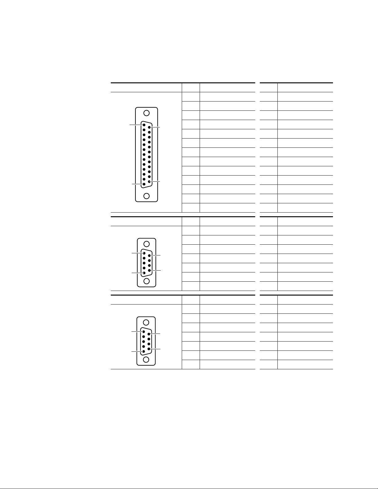
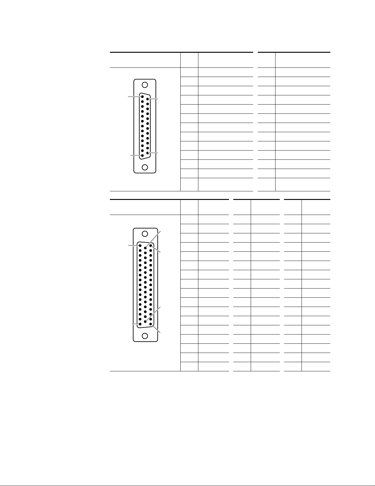
Table 2-3 contains pinout information for use with the 7500 matrices.
Table 2-3. Pinouts
OPTION Pin Function Pin Function
1 OPT_1 14 OPT_14
2 OPT_2 15 OPT_15
3 OPT_3 16 OPT_16
4 OPT_4 17 OPT_17
5 OPT_5 18 OPT_18
6 OPT_6 19 OPT_19
7 OPT_7 20 OPT_20
8 OPT_8 21 OPT_21
9 OPT_9 22 OPT_22
10 OPT_10 23 OPT_23
11 OPT_11 24 OPT_24
12 OPT_12 25 OPT_25
13 OPT_13 - -
Pin 1
Pin 13
D-25 Female
Pin 14
Pin 25
SMPTE/LTC Pin Function Pin Function
D-9 Female
Pin 1
Pin 5
CONSOLE 1 and CONSOLE 2 Pin Function Pin Function
D-9 Female
Pin 1
Pin 5
Pin 6
Pin 9
Pin 6
Pin 9
1 GND 6 NC
2LTC INPUT - 7 NC
3LTC INPUT + 8 NC
4NC 9NC
5NC --
-- --
-- --
1 GND 6 NC
2 RS-232_TX 7 NC
3 RS-232_RX 8 NC
4NC 9NC
5NC --
-- --
-- --
2-10 7500 Series Instruction Manual
Page 35
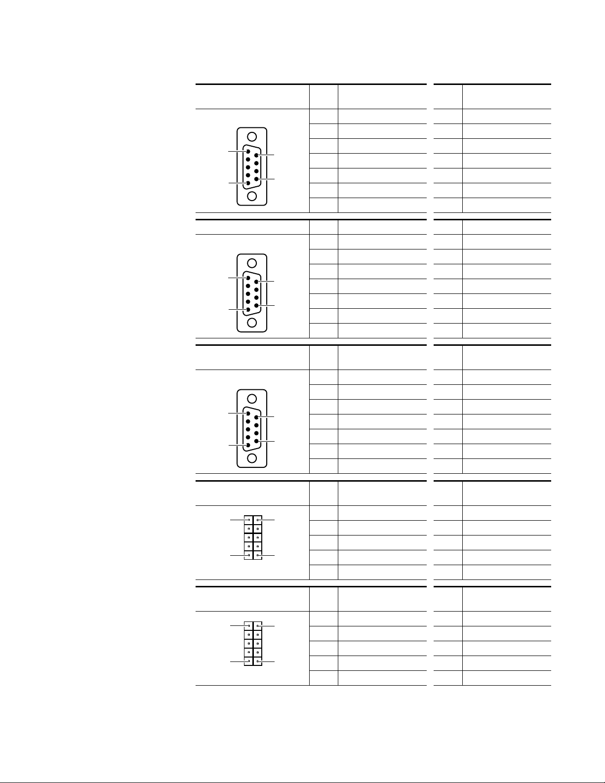
Table 2-3. Pinouts - (continued)
MC1 EXT-COM1 and
MC2 EXT-COM1
D-9 Female
Pin 1
Pin 5
EXT-COM2 Pin Function Pin Function
D-9 Female
Pin 1
Pin 5
Pin 6
Pin 9
Pin 6
Pin 9
Cabling
Pin Function Pin Function
1 GND 6 TX_COM
2 TX - 7 TX +
3 RX + 8 RX 4 RX_COM 9 GND
5NC --
-- --
-- --
1 GND 6 MC1 & MC2_TX_COM
2 MC1 & MC2_TX - 7 MC1 & MC2_TX +
3 MC1 & MC2_RX + 8 MC1 & MC2_RX 4 MC1 & MC2_RX _COM 9 GND
5NC --
-- --
-- --
ALARM
(7500WB)
D-9 Female
Pin 1
Pin 5
FAN DC/ALARM
(7500NB 256x256)
Pin 6 Pin 1
FAN DC/ALARM
(7500WB 128x128
Pin 6 Pin 1
Pin 6
Pin 9
Pin 5Pin 10
Pin 5Pin 10
Pin Function Pin Function
1 GND 6 MC2_RLY_COM
2 MC2_RLY_NO 7 NC
3NC 8NC
4 MC1_RLY_COM 9 MC1_RLY_NO
5 GND - -
-- --
-- --
Pin Function Pin Function
6FAN2_ALARM 1 MC1_RLY_NO
7FAN3_ALARM 2 MC1_RLY_NO_COM
8FAN4_ALARM 3 MC2_RLY_NO
9 24 VDC 4 MC2_RLY_NO_COM
10 GND 5 FAN1_ALARM
Pin Function Pin Function
6FAN2_ALARM 1 NC
7FAN3_ALARM 2 NC
8FAN4_ALARM 3 NC
9 24 VDC 4 NC
10 GND 5 FAN1_ALARM
7500 Series Instruction Manual 2-11
Page 36
Section 2 — Installation
Table 2-3. Pinouts - (continued)
MONITOR 1-8
(7500NB)
D-25 Female
Pin 1
Pin 13
Use 110 Ohm Shielded Twisted
Pair Cable
Pin 14
Pin 25
Pin Function Pin Function
1 Monitor 1+ 14 Monitor 1-
2 Ground 15 Monitor 2+
3 Monitor 2- 16 Ground
4 Monitor 3+ 17 Monitor 3-
5 Ground 18 Monitor 4+
6 Monitor 4- 19 Ground
7 Monitor 5+ 20 Monitor 5-
8 Ground 21 Monitor 6+
9 Monitor 6- 22 Ground
10 Monitor 7+ 23 Monitor 711 Ground 24 Monitor 8+
12 Monitor 8- 25 Ground
Ground
13
-
-
Input/Output D Connector
(7500NB)
D-50 Female
Pin 18
Pin 1
Pin 34
Pin 33
Pin 17
Pin 50
Use 110 Ohm Shielded Twisted
Pair Cable
Pin Function Pin Function Pin Function
1 Ground 18 1- 34 1+
22+192-35Ground
3 Ground 20 3- 36 3+
44+214-37Ground
5 Ground 22 5- 38 5+
66+236-39Ground
7 Ground 24 7- 40 7+
88+258-41Ground
9 Ground 26 9- 42 9+
10 10+ 27 10- 43 Ground
11 Ground 28 11- 44 11+
12 12+ 29 12- 45 Ground
13 Ground 30 13- 46 13+
14 14+ 31 14- 47 Ground
15 Ground 32 15- 48 15+
16 16+ 33 16- 49
17 Not used - - 50 Not used
2-12 7500 Series Instruction Manual
Page 37
Communications
Encore Control Frame
Managed
Ethernet Switch
0723_00_17_r0
VID
REF
AES
REF1
AES
REF2
GSC
7500NB 128X128
ETHERNET
CONT 1
ETHERNET
CONT 2
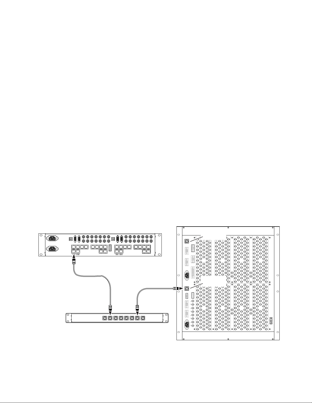
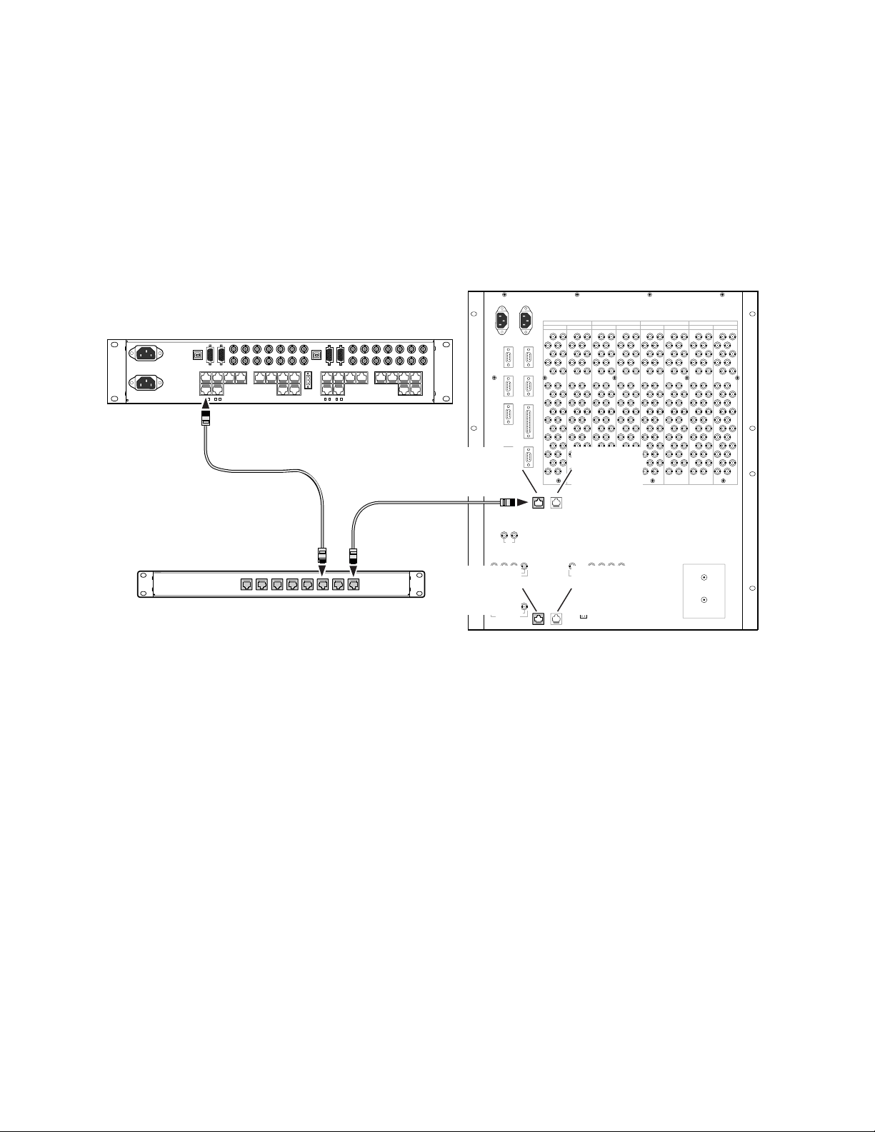
Communications between matrices and control systems use either
Ethernet or Global Serial Channel (GSC) interfaces. The Encore Control
System requires an Ethernet connection and Series 7000 requires a GSC
connection. Communications between matrices in expanded systems
requires Ethernet.
7500NB Ethernet
Ethernet is required for communication among the Encore Control Frame
and 7500NB matrices. Ethernet is also required to communicate among
matrices in 7500NB systems larger than 256x256.
Ethernet communications can be established between the Encore Control
Frame and a 7500NB matrix using either
2. One connection can be used as a primary connection and the other can
be used as a redundant connection. See Figure 2-10
The multicast signals from the 7500NB matrices are routed through a
managed Ethernet switch. Using the software and instructions that come
with the managed Ethernet switch, Virtual Local Area Networks (VLANs)
can be created to manage the communication between matrices, the Encore
Control Frame, and other equipment connected to the switch. The
managed switch must support IP multicast with Internet Group Management Protocol (IGMP).
Cabling
ETHERNET CONT 1 or ETHERNET CONT
Figure 2-10. NB and Encore Ethernet Connectors
7500 Series Instruction Manual 2-13
Page 38
Section 2 — Installation
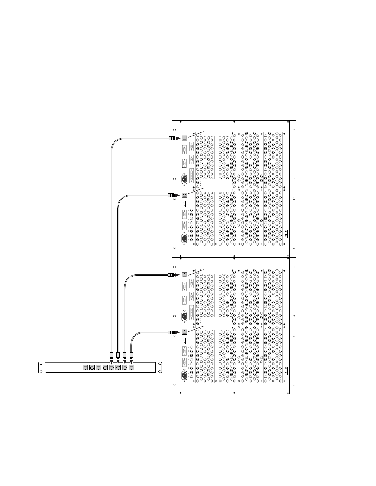
Figure 2-11 shows the Ethernet requirements for a 7500NB 512x512 that is
controlled by a Series 7000 Control System. Dedicated Ethernet Switches
are used to communicate between the matrices. One Ethernet Switch is
required for each set of up to four matrices. The switches do not have to be
in the same rack as the matrices and the standard cable length restrictions
of 100 m (328 ft) apply.
Figure 2-11. Ethernet Communication Connections in Expanded NB Systems
7500NB 512X512
ETHERNET
CONT 1
ETHERNET
CONT 2
Ethernet Switch
GSC
VID
REF
AES
REF1
AES
REF2
GSC
VID
REF
AES
REF1
AES
REF2
ETHERNET
CONT 1
ETHERNET
CONT 2
0723_00_16_r0
2-14 7500 Series Instruction Manual
Page 39
Encore Control Frame
Cabling
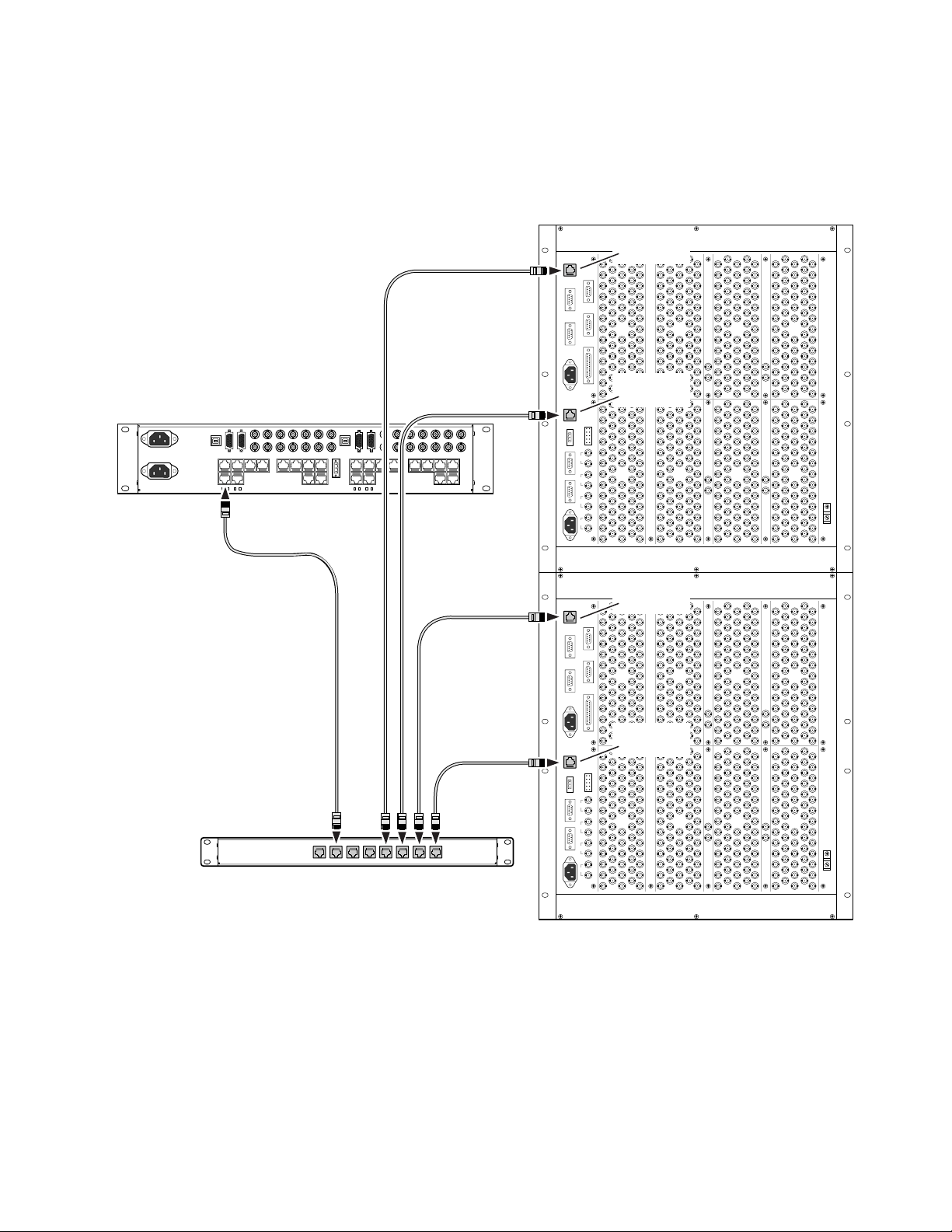
Figure 2-12 shows all the Ethernet connections for using a 7500NB 512x512
with an Encore Control System.
Figure 2-12. Ethernet Communication Connections Between Expanded 7500NB and Encore
7500NB 512X512
ETHERNET
CONT 1
ETHERNET
CONT 2
Managed
Ethernet Switch
GSC
VID
REF
AES
REF1
AES
REF2
GSC
VID
REF
AES
REF1
AES
REF2
ETHERNET
CONT 1
ETHERNET
CONT 2
7500 Series Instruction Manual 2-15
0723_00_2_r0
Page 40
Section 2 — Installation
7500WB Ethernet
Encore Control Frame
Ethernet communications can be established between the Encore Control
Frame and a 7500WB matrix using either
ERNET CONT 2. One connection can be used as a primary connection and the
other can be used as a redundant connection.
ETHERNET CONT 2 are reserved for future use.
Figure 2-13. WB and Encore Ethernet Connectors
7500WB 128X128
MC1 ETHERNET CONT 1 or MC1 ETH-
MC2 ETHERNET CONT 1 and MC2
INPUTS INPUTSOUTPUTS OUTPUTS
193-224 129-160 193-224 129-160 65-96 1-32 65-96 1-32
Ethernet Switch
MC1
ETHERNET
CONT 1
GSC
1
MC1
ETHERNET
1 2 1 2
CONT 2
MC1
DIGITAL VIDEO REF
MC2
ETHERNET
CONT 1
1 2 3 4
2
MC2
OUT
IN
MONITORVIDEO REF
MC2
ETHERNET
CONT 2
+
_
0723_00_9_r0
2-16 7500 Series Instruction Manual
Page 41

Global Serial Channel
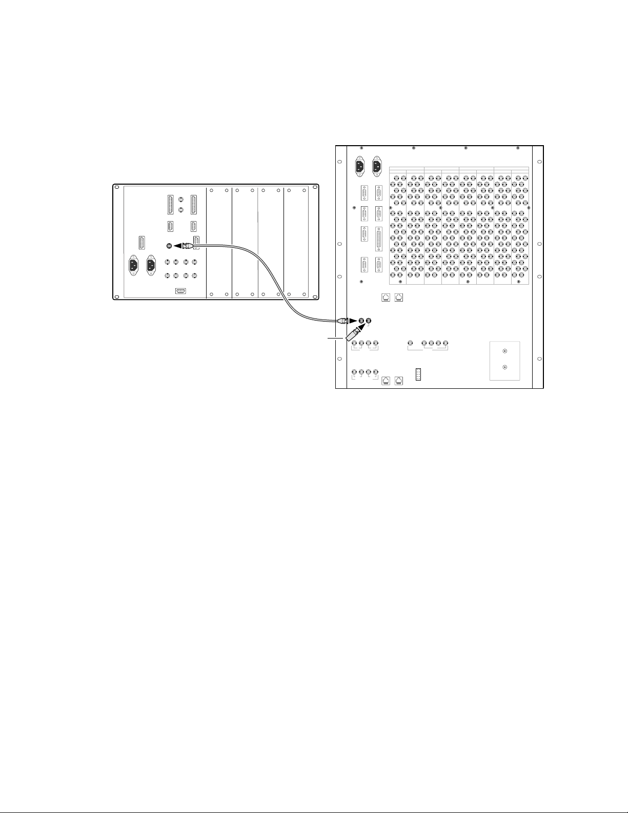
The Global Serial Channel (node bus) must be daisy chained from the
control frame, between matrices, and terminated at the end of the bus as
shown in Figure 2-14.
Note 7500NB systems 512x512 and larger require Ethernet cabling to communi-
Figure 2-14. NB Global Serial Channel Connectors
7000 Control Frame
Cabling
cate between matrices. See 7500NB Ethernet on page 2-13 for Ethernet
requirements.
7500NB 512X512
75 Ohm Terminator
GSC
VID
REF
AES
REF1
AES
REF2
GSC
VID
REF
AES
REF1
AES
REF2
7500 Series Instruction Manual 2-17
0723_00_3_r0
Page 42
Section 2 — Installation
7000 Control Frame
The 7500WB Global Serial Channel connection has the same requirements
as the 7500NB. See Figure 2-15.
Figure 2-15. WB Global Serial Channel Connectors
7500WB 128X128
INPUTS INPUTSOUTPUTS OUTPUTS
193-224 129-160 193-224 129-160 65-96 1-32 65-96 1-32
Global Serial Channel
(node bus)
75 Ohm Terminator
GSC
1
1 2 1 2
MC1
DIGITAL VIDEO REF
1 2 3 4
2
OUT
IN
MONITORVIDEO REF
+
_
MC2
0723_00_8_r0
References
7500NB AES Reference
7500NB systems have dual AES reference inputs. Two AES sync reference
loop-thru inputs provide a 48 kHz AES formatted signal upon which the
router bases its re-synchronization to frame and block boundaries. This
signal is assumed to be present for the router to be called synchronous. Two
inputs are provided for redundancy. In the event of loss of one AES reference the router will default to the second reference if one is present, otherwise, it will default to asynchronous operation.
In systems with mixed module types (async and sync input and output
modules) the reference signal is required for the synchronous modules to
function properly. In systems that contain only asynchronous input and
output modules the reference signal is not required.
Figure 2-16 shows the flow of the AES reference signal. All signals have to
be terminated at the end of the flow . Cables must be as short as possible and
each cable pair must be the same length. Input Signal 1 and Input Signal 2
is one cable pair . Output Signal 1 and Output Signal 2 is another cable pair.
2-18 7500 Series Instruction Manual
Page 43
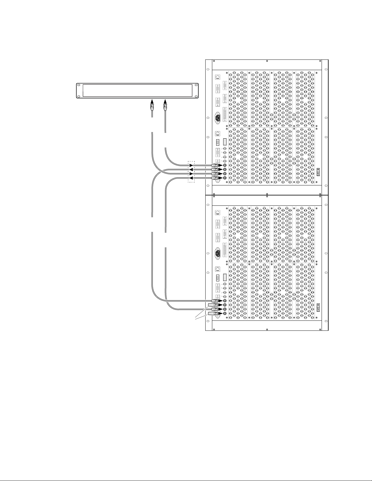
Figure 2-16. NB AES Reference Connectors
AES Reference Generator
Output
Signal 2
Output
Signal 1
Signal
Flow
7500NB 512X512
GSC
VID
REF
AES
REF1
AES
REF2
Cabling
Input
Signal 1
Input
Signal 2
75 Ohm Terminators
GSC
VID
REF
AES
REF1
AES
REF2
0723_00_1_r0
7500 Series Instruction Manual 2-19
Page 44
Section 2 — Installation
7500NB Video Reference
Video Reference Generator (Color Black)
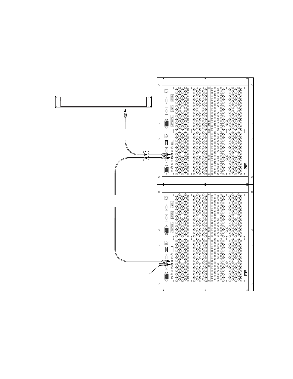
The 7500NB requires a Video Reference. Any Composite Analog Video
Sync signal will work. Color Black is recommended. See Figure 2-17.
Figure 2-17. NB Video Reference Connectors
7500NB 512X512
Output
Signal 1
Signal
Flow
GSC
VID
REF
AES
REF1
AES
REF2
Input
Signal 1
75 Ohm Terminator
GSC
VID
REF
AES
REF1
AES
REF2
0723_00_13_r0
2-20 7500 Series Instruction Manual
Page 45
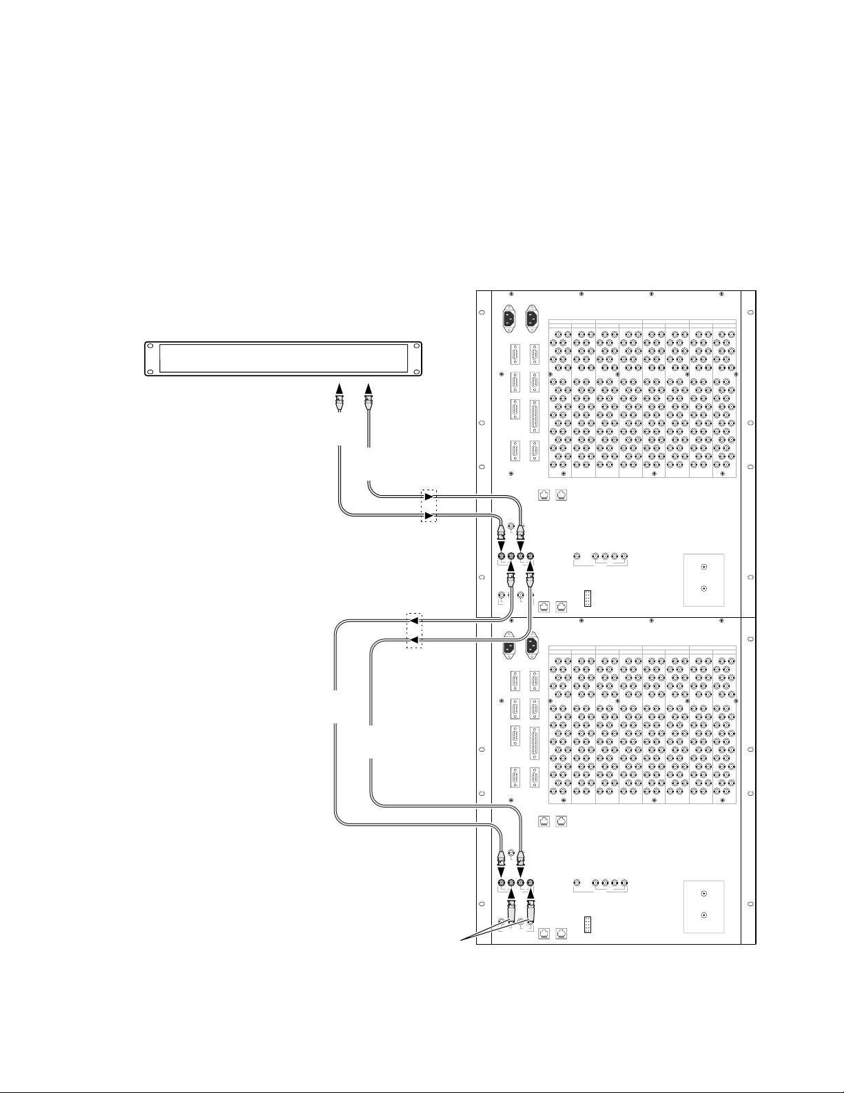
7500WB Video Reference
The 7500WB Video Refer ence is used to determine the r outer switch point.
Two sets of video references allow the router to switch on two differ ent vertical rates. Any Composite Analog Video Sync signal will work. Color Black
is recommended. See Figure 2-18.
The 7500 WB Digital Video References are not currently used.
Figure 2-18. WB Video Reference Connectors
Video Reference Generator (Color Black)
Output
Signal 2
Output
Signal 1
Signal
Flow
7500WB 128X128
INPUTS INPUTSOUTPUTS OUTPUTS
193-224 129-160 193-224 129-160 65-96 1-32 65-96 1-32
Cabling
Input
Signal 1
Input
Signal 2
75 Ohm Terminators
Signal
Flow
GSC
1
1 2 1 2
MC1
DIGITAL VIDEO REF
GSC
1
1 2 1 2
MC1
DIGITAL VIDEO REF
1 2 3 4
2
MC2
193-224 129-160 193-224 129-160 65-96 1-32 65-96 1-32
2
MC2
OUT
IN
MONITORVIDEO REF
INPUTS INPUTSOUTPUTS OUTPUTS
1 2 3 4
OUT
IN
MONITORVIDEO REF
+
_
+
_
0723_00_14_r0
7500 Series Instruction Manual 2-21
Page 46
Section 2 — Installation
Power
AC Connections
Frames may be powered using either an AC power source, or a 48V DC
power source. It is also possible to cable a matrix using an AC power sour ce
and a 48V DC power source at the same time. If a matrix has both AC and
DC power sources available it will use whichever power source can meet
its power level demand. So if the AC power source fails then the DC power
source would feed the matrix, and if the DC power starts to fall the AC
power would feed the matrix. AC and DC power sources ar e kept separate
with no feedback, so the AC power source will not char ge batteries used in
a connected DC power source.
The 7500NB 256x256 and the 7500WB 128x128 come with one power
supply . The 7500WB 256x256 comes with two power supplies. Redundancy
is provided by adding additional power supplies.
48V DC Connections
WARNING Do not apply a 48V DC power source until all 48V DC connections on the
7500NB 48V DC
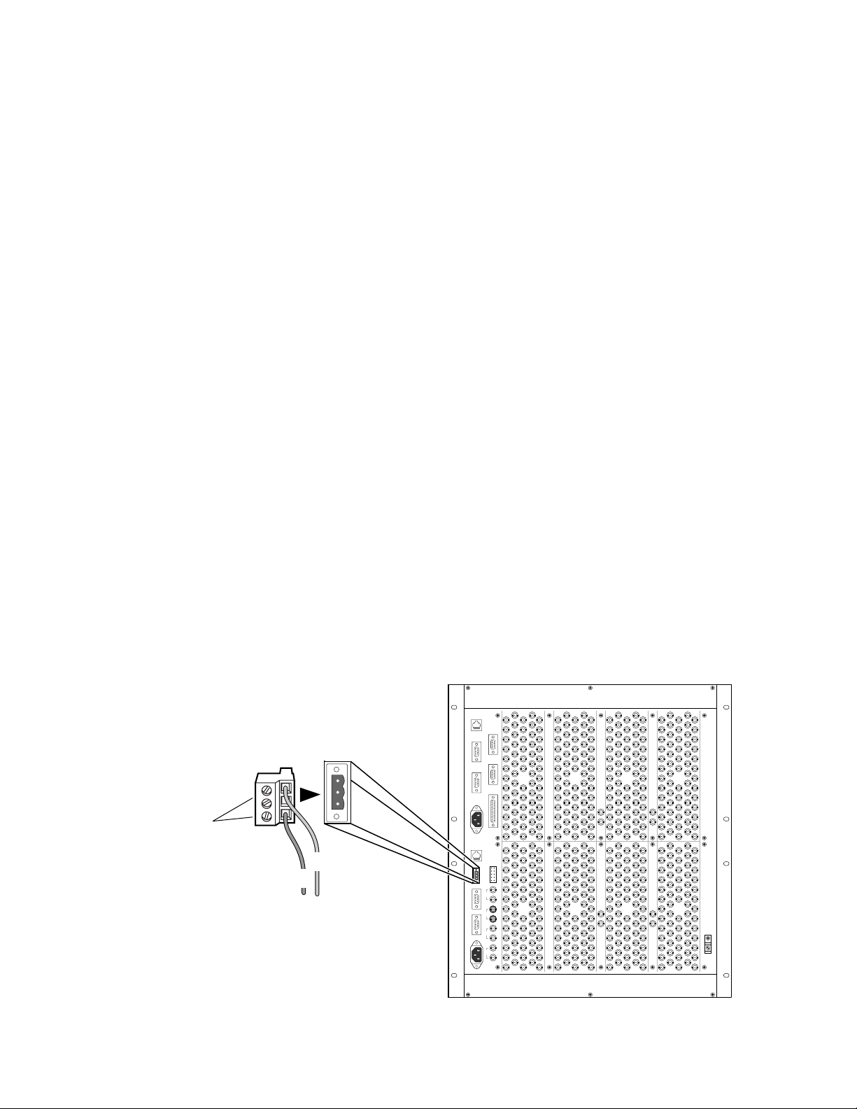
The 7500NB 48V DC connection requires 12 AWG (3.31 mm2) wire and a 3pin female terminal block connector. See Figure 2-19.
Figure 2-19. NB 48V DC Connection
3-pin Female
Terminal Block
Connector
Tighten screws
to secure wires
Negative
7500 matrices are complete and secure.
3-pin Male
Terminal Block
Connector
Positive
GSC
VID
REF
AES
REF1
AES
REF2
2-22 7500 Series Instruction Manual
0723_00_15_r0
Page 47
7500WB 48V DC
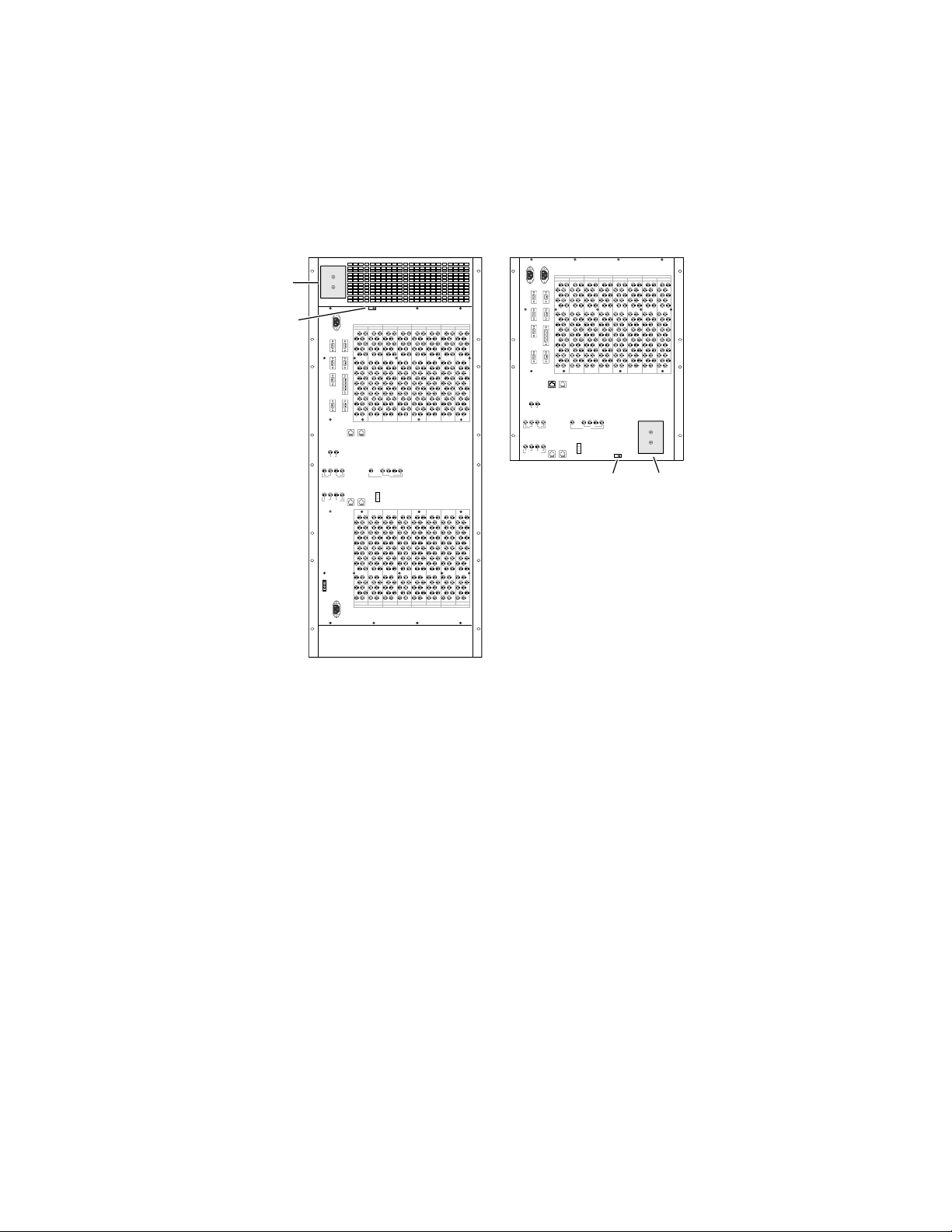
Refer to Figure 2-20, Figure 2-21, and Figure 2-22 when performing the fol-
lowing procedure.
Figure 2-20. WB 48V DC Cover Plate and Retainer Locations
48V DC
Entry Module
cover plate
Cable Retainer
+
_
INPUTS INPUTSOUTPUTS OUTPUTS
193-224 129-160 193-224 129-160 65-96 1-32 65-96 1-32
Power
7500WB 128X1287500WB 256X256
INPUTS INPUTSOUTPUTS OUTPUTS
193-224 129-160 193-224 129-160 65-96 1-32 65-96 1-32
1
1 2 1 2
MC1
DIGITAL VIDEO REF
GSC
1
1 2 1 2
MC1
GSC
1 2 3 4
2
MC2
OUT
IN
MONITORVIDEO REF
DIGITAL VIDEO REF
1 2 3 4
IN
OUT
MONITORVIDEO REF
Cable
Retainer
+
_
48V DC
Entry Module
2
MC2
cover plate
225-256 161-192 225-256 161-192 97-128 33-64 97-128 33-64
INPUTS INPUTSOUTPUTS OUTPUTS
0723_00_12r0
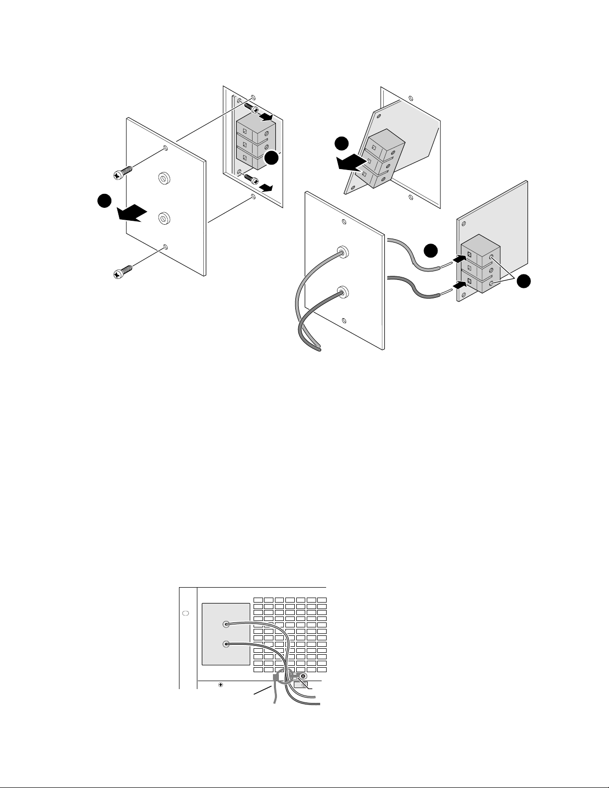
1. Remove cover screws. Set cover aside.
2. Remove screws from 48V DC Entry module.
3. Remove 48V DC Entry module.
4. Thread a 6 AWG (13.30 mm
2
) positive connector wire through the top
hole on the cover.
5. Secure wire to 48V DC Entry module by inserting the wire in the top
slot and tightening the retention screw.
7500 Series Instruction Manual 2-23
Page 48
Section 2 — Installation
1
Figure 2-21. WB 48V DC Connector
3
2
+
_
+
4
Positive
_
Negative
0723_00_11r2
6. Thread a 6 AWG (13.30 mm
bottom hole on the cover.
7. Secure wire to 48V DC Entry module by inserting the wire in the
bottom slot and tightening the retention screw. The middle slot is not
used.
8. Reseat the 48V DC Entry module in the matrix.
9. Secure the 48V DC Entry module with screws.
10. Replace the cover and secure with screws.
11. Restrain wires using a cable tie looped through the retainer on the back
of the frame.
2
) negative connector wire through the
5
Tighten
screws
Figure 2-22. WB 48V DC Cable Retainer and Tie
+
_
0528_01_12r1
Cable Tie
2-24 7500 Series Instruction Manual
Cable Retainer
Page 49

Configuration
Matrix configuration procedures are dependent upon how the matrix fits
within its resident system and how that system is controlled. If you are
using a Series 7000 Control System you will generally need to follow the
instructions for matrix configuration found in the Series 7000 Configuration
Manual. In some cases, however, you must use 7500-specific settings. This
section highlights those distinctions.
7500NB Configuration
The 7500NB matrices can be controlled by the Series 7000 Control System.
Series 7000 Control of 7500NB
Section 3
The Matrix Controller in the 7500NB matrix communicates with the MCPU
in the Series 7000 Control System. The configuration of the Matrix Controller is handled by the Series 7000 Configuration Editor GUI. The
7500NB-specific settings for the Matrix Controller are applied during the
Configured Node Controller (CNC) and Physical Matrix procedures. A
separate Configured Node Controller record is required for each 7500NB
matrix in the system. In a single system, that has multiple 7500NB matrices,
all of the CNCs for the 7500NB matrices must be combined into a single
Physical Matrix. For example, a system that contains a 7500 NB 256x256 (1
matrix frame) would be configured with 1 CNC and 1 Physical Matrix. A
system that contains a 7500 NB 1024x1024 (8 matrix frames) would be configured with 8 CNCs and 1 Physical Matrix.
7500 Series Instruction Manual 3-1
Page 50
Section 3 — Configuration
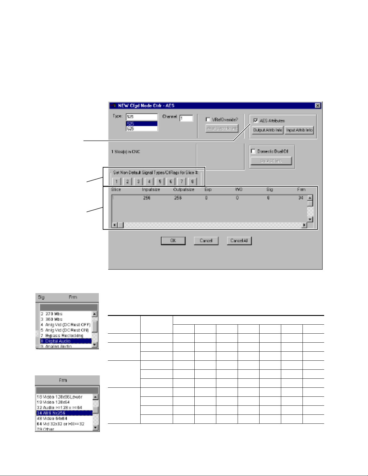
New AES Configured Node Controller Settings
AES Attributes allow
individual settings for
inputs and outputs.
Do not use this feature to
change the signal type on
a 7500NB Audio frame.
All inputs and outputs are
signal type 8.
Note 7500 Narrow Band matrices must have separate configured Node Controller
(CNC) templates for each set of 256 Outputs. Do not configure a single CNC
with multiple slices.
Figure 3-1. Cfgd Node Ctrlr Window With AES Settings
Settings from Table 3-1
are entered here.
Sig = Signal type. All 7500NB
matrices use selection 8,
Digital Audio.
Frm = Frame type. All 7500NB
matrices use selection 34,
AES Nx256.
In the multi-column window, click the gray area immediately beneath a
column heading and enter settings as indicated in Table 3-1.
Table 3-1. 7500 Narrow Band Series Matrix Settings
Matrix Size CNC
256x256 MC1 1 256 256 0 0 8 34
512x512
768x512
1024x512
MC1 1 512 256 0 0 8 34
MC2 1 512 256 0 0 8 34
MC1 1 768 256 0 0 8 34
MC2 1 768 256 0 0 8 34
MC3 1 768 000834
MC1 1 1024 256 0 0 8 34
MC2 1 1024 256 0 0 8 34
MC3 1 1024 000834
MC4 1 1024 000834
Slice Inputs OutSize Exp
Multiple Column Headings
a
WO
a
Sig Frm
3-2 7500 Series Instruction Manual
Page 51
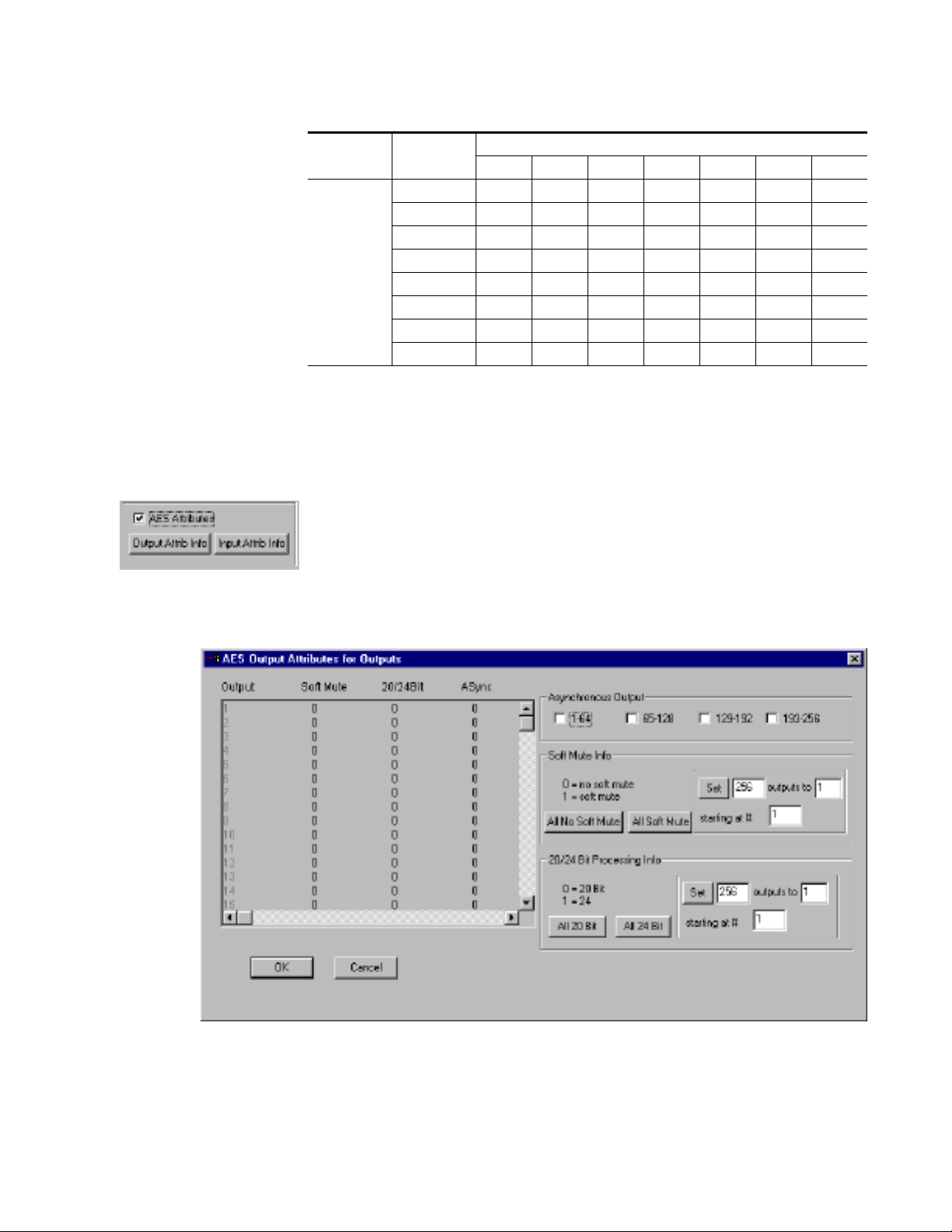
Table 3-1. 7500 Narrow Band Series Matrix Settings - (continued)
7500NB Configuration
Matrix Size CNC
1024x1024
a
Settings for Exp and WO must always be set to 0 (zero).
AES Attributes
This option in the Cfgd Node Ctrlr Window is used to apply AES Audio
attributes to Inputs and Outputs in the 7500NB matrices.
If the frame you’re configuring supports AES and this box is checked the
Output Attrib Info and Input Attrib Info buttons are activated.
1. Click the Output Attrib Info button to bring up the AES Output Attributes
for Outputs window.
Multiple Column Headings
Slice Inputs OutSize Exp
MC1 1 1024 256 0 0 8 34
MC2 1 1024 256 0 0 8 34
MC3 1 1024 000834
MC4 1 1024 000834
MC5 1 1024 256 0 0 8 34
MC6 1 1024 256 0 0 8 34
MC7 1 1024 000834
MC8 1 1024 000834
a
WO
a
Sig Frm
Figure 3-2. AES Output Attributes for Outputs Window
This window allows the outputs to be set individually or in groups. If
you were configuring a matrix that contained Asynchronous Output
modules then you would use the check boxes under
Asynchronous Output
7500 Series Instruction Manual 3-3
Page 52
Section 3 — Configuration
to set groups of 64 outputs to Asynchr onous. If you were configuring a
system that had some Asynchronous Input modules (one or just a few)
and wanted to assign a few Outputs on a Synchronous Output module
to pass asynchronous signals, then use the individual settings under
the
ASync column.
Outputs can be assigned
individually, in groups, or by using the
Soft Mute/No Soft Mute
Soft Mute/No Soft Mute and 20/24 Bit Processing
All buttons.
The Soft Mute/No Soft Mute attribute is a soft mute or alignment of one
signal’s amplitude to another signal’s amplitude at switching. This soft
mute prevents a crack or pop at switching.
20/24 Bit
The 20/24 Bit attribute determines how the signal bits are processed. A
signal has 24 bits with the last four bits designated as auxiliary (AUX)
bits.
In
20 bit mode the four AUX bits pass through the router unaffected by
any processing. If left and right channels are swapped, the four AUX
bits stay in the same place. If the signal is muted, the four AUX bits are
not muted.
In
24 bit mode the router will treat the four AUX bits as though they are
part of the audio data. If left and right channels are swapped, the four
AUX bits will swap locations. If the audio is muted, the four AUX bits
will be muted.
2. After the Output attributes are assigned click Ok to return to the New
Cfgd Node Ctrlr window.
3. Click the Input Attrib Info button to bring up the AES Input Attributes for
Inputs window.
3-4 7500 Series Instruction Manual
Page 53
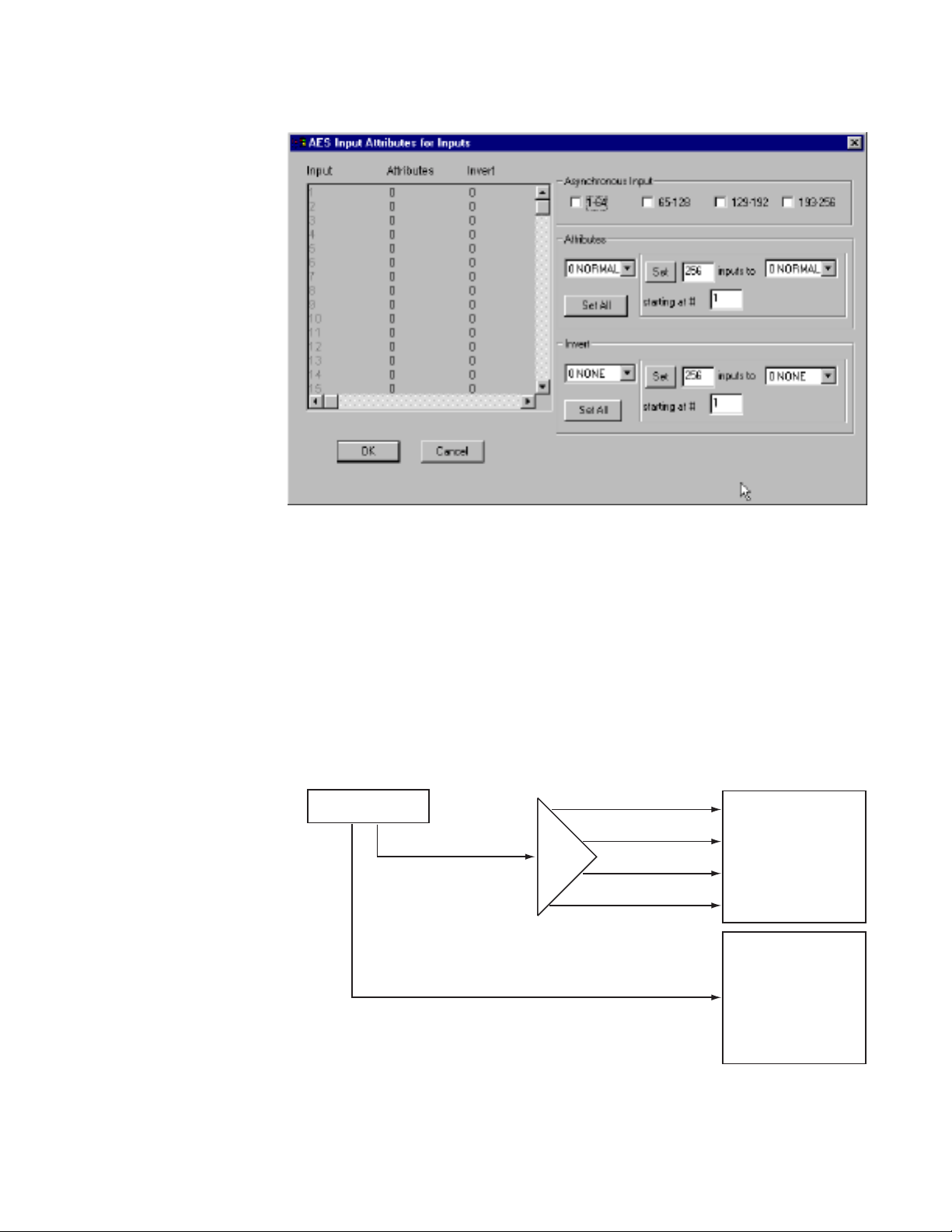
Figure 3-3. AES Inputs Attributes for Inputs Window
7500NB Configuration
This window allows the inputs to be set individually or in groups. If
you were configuring a matrix that contained Asynchronous Input
modules then you would use the check boxes under
Asynchronous Input to
set groups of 64 inputs to Asynchronous.
Inputs can be assigned Attribute and Invert options, individually, in
groups, or by using the
All buttons.
Attributes affect the way the signal is routed through the matrix.
Figure 3-4 and Figure 3-5, show how a signal is routed. Table 3-2 shows
how it is affected by the attribute settings.
Figure 3-4. Audio Signal Splitting
VTR
Audio Signal (VTR)
DA
Video Signal
VTRA
VTRB
VTRC
VTRD
7500 NB
Audio Frame
Video Frame
7500 Series Instruction Manual 3-5
Page 54
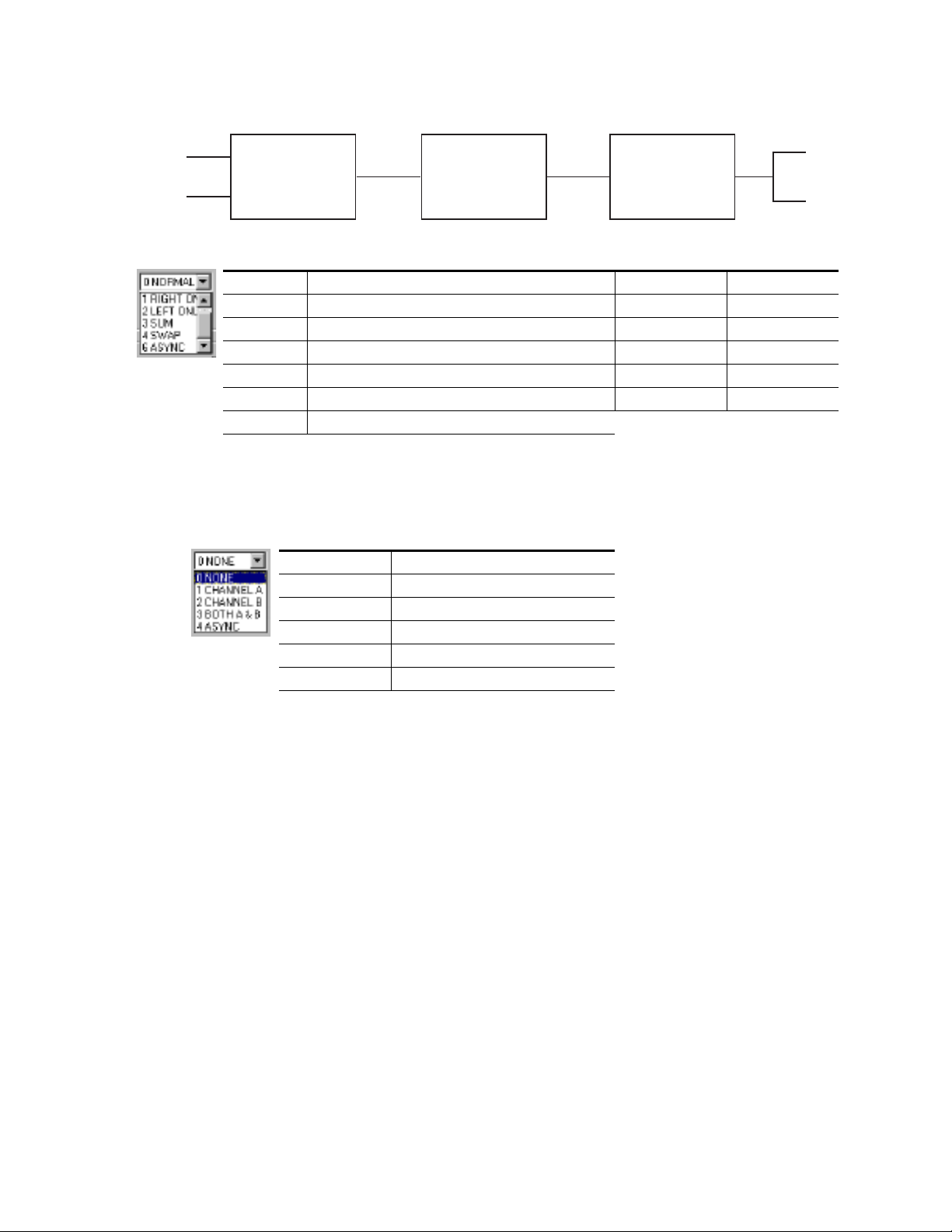
Section 3 — Configuration
Figure 3-5. Signal Flow
Right (100 Hz)
Left (1000 Hz)
Analog to Digital
Converter
Table 3-2. Attribute Options
Attribute Definition 100 Hz (Right) 1000 Hz (Left)
Normal Defaults are assigned to all Inputs. 100 Hz 1000 Hz
Right Only Right Channel Audio will be routed to the assigned Input. 100 Hz 100 Hz
Left Only Left Channel Audio will be routed to the assigned Input. 1000 Hz 1000 Hz
Sum Frequencies of the Right and left Channel are added together. 1100 Hz (R+L) 1100 Hz (R+L)
Swap Left and Right Channels are swapped. 1000 Hz 100 Hz
Async Asynchronous signals are routed.
7500 NB
Digital to Analog
Converter
Invert options assign the invert (opposite logic state) of the signal to
an Input using the settings in Table 3-3.
Table 3-3. Invert Options
Attribute Definition
None Signal is not changed.
Invert Channel A Channel A audio is inverted.
Invert Channel B Channel B audio is inverted.
Both A & B Channel A and Channel B audio is inverted.
Async Asynchronous signals are routed.
Right
Left
4. After the Input attributes are assigned click OK to return to the NEW
Cfgd Node Ctrlr window.
Physical Matrix
When configuring this, remember that the 7500 NB Series must have one Physical Matrix that includes all of the 7500 NB matrices in the system. For example,
a system that contains a 7500 NB 256x256 (1 matrix frame) would be configured with 1 CNC and 1 Physical Matrix. A system that contains a 7500
NB 1024x1024 (8 matrix frames) would be configured with 8 CNCs and 1
Physical Matrix.
3-6 7500 Series Instruction Manual
Page 55
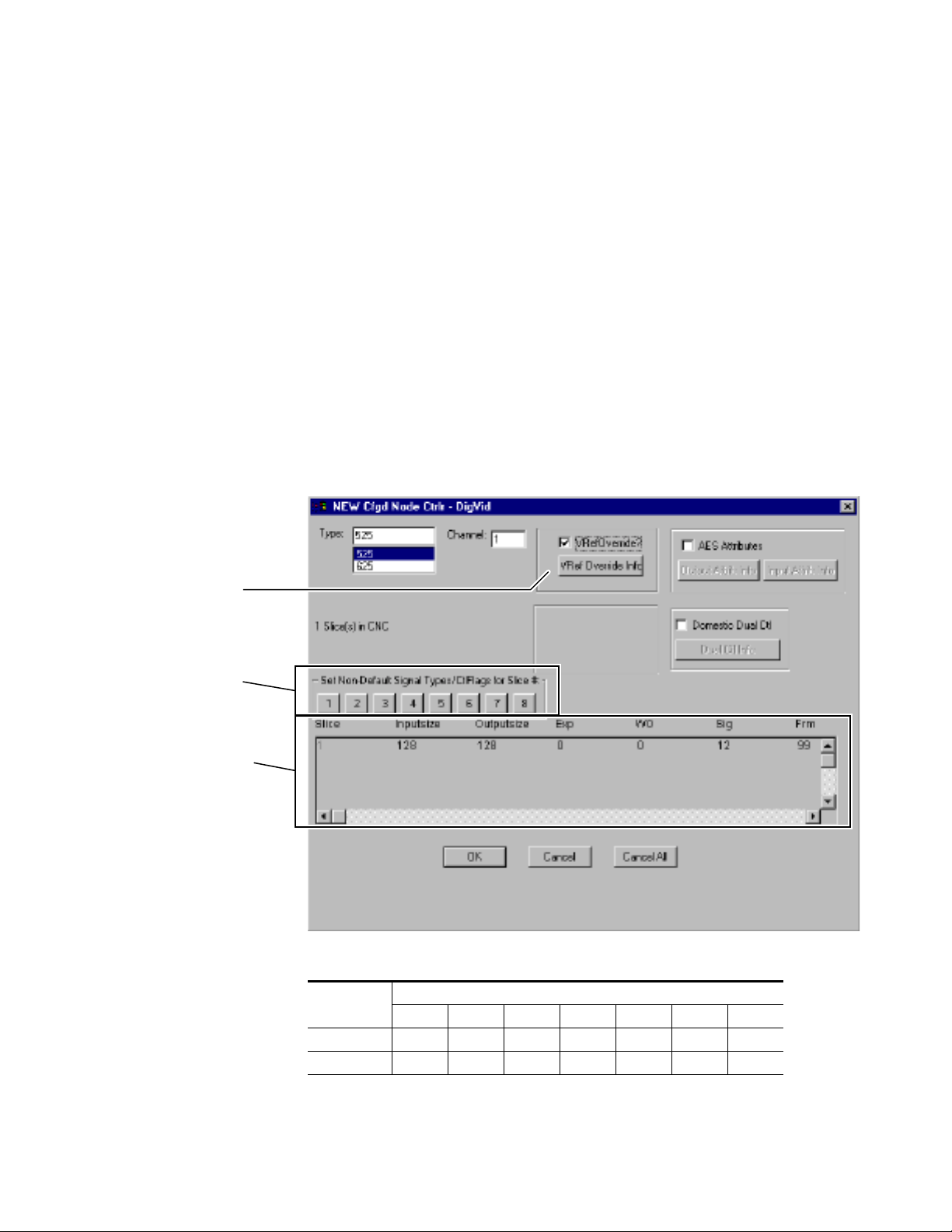
7500WB Configuration
The 7500WB matrices can be controlled by the Series 7000 Control System.
Series 7000 Control of 7500WB
The Matrix Controller in the 7500WB matrix communicates with the MCPU
in the Series 7000 Control System. The configuration of the Matrix Controller is handled by the Series 7000 Configuration Editor GUI. The
7500WB-specific settings for the Matrix Controller are applied during the
Configured Node Controller (CNC) procedures.
The 7500WB matrix can have a second Video Reference.
New 7500WB Configured Node Controller Settings
Figure 3-6. Cfgd Node Ctrlr Window With AES Settings
7500WB Configuration
VRef Override is used
to enter settings for a
second Video Reference.
Use this feature to
change the signal type
for individual Inputs
and Outputs on a
7500WB matrix.
Settings from Table 3-4
are entered here.
Table 3-4. 7500 Wide Band Series Matrix Settings
Matrix Size
128x128 1 128 128 0 0 12 98
256x256 1 256 256 0 0 12 99
a
Settings for Exp and WO must always be set to 0 (zero).
b
Any Digital Video Signal type may be used
Slice Inputs OutSize Exp
Multiple Column Headings
a
WO
a
Sig
b
Frm
7500 Series Instruction Manual 3-7
Page 56

Section 3 — Configuration
Signal types from the Sig column drop-down list that can be used with a
7500WB frames are
RECLOCKING), 10 (540 MBPS), 11 (1.485 GBPS), and 12 (AUTO RECLOCKING). Auto
0 (143 MBS), 1 (177 MBS), 2 (270 MBS), 3 (360 MBS), 7 (BYPASS
Reclocking will automatically reclock to any of the signal rates. Bypass
reclocking will pass any signal rate without reclocking. Selecting a signal
rate such as 270 will set the reclocker to 270.
Individual Inputs and Outputs can be configured with different signal
types using the
Note Switching an Input configured with one type of signal to an Output configured
with a different signal type will cause a conflict. The conflict is resolved by the
matrix. If either one of the signal types is Bypass Reclocking then the matrix
will bypass reclocking. If neither one of the signal types is Bypass Reclocking
then the matrix will auto reclock the signal.
Set Non-Default Signal Types: /CtlFlags: for Slice# button number 1.
Frame types that can be used with a 7500WB frame are either 98 7500WB
256X256 or 99 7500WB 128X128.
VRef Override
This option in the Cfgd Node Ctrlr Window is used to enter a setting for a
second Video Reference in the 7500WB matrices.
1. Select VREF OVERRIDE? check box if V ideo Reference 2 is going to be used.
2. Click on VREF OVERRIDE INFO to access the Vert Reference Override
3. Assign 1 or 2 to each Output. Outputs may have different VRef signal
4. Select 525 (NSTC) or 625 (PAL) as a setting for TYPE FOR REF2.
The VRef Override is used to set 525 or 625 for Video Reference 2 and
to assign Video Reference 1 or Video Reference 2 to each Output.
window. See Figure 3-7.
types within a slice.
3-8 7500 Series Instruction Manual
Page 57
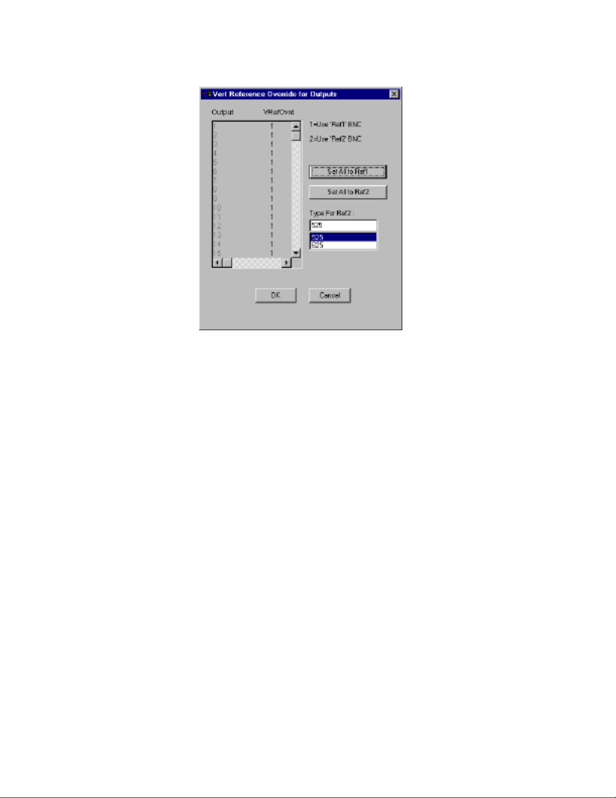
Figure 3-7. Vert Reference Override Window
7500WB Configuration
5. Click OK to return to the Cfgd Node Ctrlr window.
6. Click OK to accept the Cfgd Node Ctrlr settings.
7500 Series Instruction Manual 3-9
Page 58

Section 3 — Configuration
3-10 7500 Series Instruction Manual
Page 59

Functional Description
Matrix Controller
The Matrix Controller (MC) modules are used in 7500 Series models. MCs
are designed to work in pairs (one primary, one backup) to provide failure
resistance. The primary MC provides all required functions; the backup is
ready to take over should the primary unit fail. Control logic facilitates
orderly change of control between the two modules and ensures that only
one module at a time controls the external serial busses.
Control consists of messages created to set matrix crosspoints, and the
return from the MC contains true tally status back to the control system.
The MC module can be inserted into a powered frame. To ensure that the
system power supply is not disturbed, a pre-charge resistor is connected in
series with one of the rear connector pins. The corresponding pin on the
backplane connector is longer than any of the other power pins. This allows
the pre-charge pin to make connection before the others.
Section 4
A 25-pin D connector labeled
optional interface.
A SMPTE Vertical Interval Time Code (VITC) reader is used to allow preloaded events to be triggered on a particular SMPTE frame number. This
signal must be applied to the single coax vertical reference input.
Vertical interval reference is still required for crosspoint switching tasks.
This is an analog video input which can be NTSC or P AL. This input is pr ocessed to extract vertical sync and odd/even field (if any) information. Predefined progammable logic device (PLD) logic is used to create a switching
strobe that is offset into line 10 for NTSC or line 6 for PAL. A video presence
detector interrupts the processor if the video refer ence is missing. If this reference is missing then a fake sync is generated at a default asynchronous
interval.
7500 Series Instruction Manual 4-1
OPTION is connected to the MC for use as an
Page 60

Section 4 — Functional Description
Matrix Modules
The 7500 matrix modules are identified in Table 4-1.
Table 4-1. 7500 Matrix Modules
Label NB WB Description
32 INPUT - √ Wide band digital video input module (page 4-2)
64X64 CROSSPOINT - √ Wide band digital video 64x64 crosspoint module 7500WB 128x128 (page 4-2)
128X64 CROSSPOINT √ - 128x64 Audio crosspoint module (page 4-4)
128X64 CROSSPOINT - √ Wide band digital video 128x64 crosspoint module 7500WB 256x256 (page 4-2)
NB DIGITAL INPUT √ - Asynchronous audio input module (page 4-4)
NB DIGITAL OUTPUT √ - Asynchronous audio output module (page 4-4)
SD EXPANSION BYPASS - √ Serial digital video bypass switch (page 4-2)
SD OUTPUT - √ Wide band standard definition digital video output module (page 4-3)
SYNC AES INPUT √ - Synchronous AES audio input module (page 4-4)
SYNC AES OUTPUT √ - Synchronous AES audio output module (page 4-4)
WB 128 DC DISTRIBUTION - √ Wide band 48 VDC power distribution module (page 4-3)
WB EXPANSION SWITCH - √ Reclocking serial digital video 2x1, 4x1, 8x1, 16x1, and 32x1 switch (page 4-3)
WB MONITOR - √ Wide band digital video monitor module (page 4-3)
WB OUTPUT - √ Wide band digital video output module (page 4-3)
WB SD INPUT - √ Wide band standard definition digital video input module (page 4-3)
7500WB Modules
32 Input
The module labeled 32 INPUT provides 32 equalized Input channels. The
module supports data rates from 19 Mbps to 1.5 Gbps. There are no user
adjustments on the module.
64x64 Crosspoint
The module labeled 64X64 CROSSPOINT is a 64 Input by 64 Output Crosspoint
array. This module is used in the 7500WB 128x128 frame. There are no user
adjustments on the module.
128x64 Crosspoint
The module labeled 128X64 CROSSPOINT is a 128 Input by 64 Output Crosspoint array . This module is used in the 7500WB 256x256 frame.Ther e are no
user adjustments on the module.
SD Expansion Bypass
The module labeled SD EXPANSION BYPASS provides a path from Input 1 to
Output 1, a second path from Input 2 to Output 2, a third path from Input
3 to Output 3, etc. for 32 signals. The main purpose of the SD Expansion
4-2 7500 Series Instruction Manual
Page 61

Matrix Modules
Bypass module is to allow the expansion frame to be pre-wired and tested
for future expansion. The supported data rates are 143 Mbps, 177 Mbps,
270 Mbps, and 360 Mbps. There are no user adjustments on the module.
SD Output
The module labeled SD OUTPUT pr ovides 32 reclocked output channels with
selectable bypass mode for each channel. The supported reclocked data
rates are 143 Mbps, 177 Mbps, 270 Mbps, and 360 Mbps. There are no user
adjustments on the module.
WB 128 DC Distribution
The module labeled WB 128 DC DISTRIBUTION provides DC connections for the
48V DC Entry module. It also distributes the 48V power to the frame and
processes the external fan alarm outputs. There are no user adjustments on
the module.
WB Expansion Switch
The module labeled WB EXPANSION SWITCH is a reclocking serial digital video
expansion switch that can be configured as a 2x1, 4x1, 8x1, 16x1, or 32x1.
There are no user adjustments on the module.
WB Monitor
The module labeled WB MONITOR provides 4 channels of monitoring. It also
provides for one channel of multi-standard CRC error detection. Five
signals are sent from each Output Module to the Monitor Module for
output monitoring. One signal is sent from each Crosspoint Module for
Input monitoring. The
used between 7500WB matrices in expanded systems. There are four
connectors which can be used for monitoring. When used with a 7000
Series Control System the four connectors provide the same signal to different monitors. When used with an Encore Control System the four connectors can provide up to four different signals to four different monitors.
A fifth video channel is used for CRC checking, but the signal does not
leave the Monitor Module. There are no user adjustments on the module.
IN connector for use with an external input signal is
OUT
WB Output
The module labeled WB OUTPUT provides 32 reclocked output channels with
selectable bypass mode for each channel. The supported reclocked data
rates are 143 Mbps, 177 Mbps, 270 Mbps, 360 Mbps, 540 Mbps, 1.485 Gbps,
and 1.485/1.001 Gbps. There are no user adjustments on the module.
WB SD Input
The module labeled WB SD INPUT pr ovides 32 equalized input channels. The
supported data rates are from 19 Mbps to 360 Mbps. There are no user
adjustments on the module.
7500 Series Instruction Manual 4-3
Page 62

Section 4 — Functional Description
7500NB Modules
128x64 Crosspoint
The module labeled 128X64 CROSSPOINT is a Narrow Band (NB) audio crosspoint module used in 7500 Series Narrow Band frames. This module inputs
128 single ended digital inputs and then outputs 64 single ended outputs.
The module does not manipulate the data and can be used for data rates up
to 50 Mbps. There are no user adjustments on the module.
NB Digital Output
The module labeled NB DIGITAL OUTPUT can be used as an asynchr onous AES
audio output module in 7500 Series Narrow Band frames. This module provides 64 outputs of any digital rate up to 50 Mbps. There are 2 monitoring
channels on each module. There are no user adjustments on the module.
NB Digital Input
The module labeled NB DIGITAL INPUT can be used as an asynchronous AES
audio input module in 7500 Series Narrow Band frames. This module provides 64 inputs of any digital rate up to 50 Mbps.There are no user adjustments on the module.
Sync AES Input
The module labeled SYNC AES INPUT is a synchronous AES audio input
module used in 7500 Series Narrow Band frames. This module receives and
reclocks 64 separate AES streams and synchronizes them to a 48 kHz
system clock. A 27 MHz system clock is used as a sample clock for the input
data. There are no user adjustments on the module.
Sync AES Output
The module labeled SYNC AES OUTPUT is a synchronous AES audio output
module used in 7500 Series Narrow Band frames. This module provides 64
AES outputs that are reclocked and reformatted AES data streams. There
are 2 monitoring channels on each module. There are no user adjustments
on the module.
4-4 7500 Series Instruction Manual
Page 63

Maintenance and Troubleshooting
Field Replaceable Units
Modules and Power Supplies are not serviced in the field. Replace faulty
modules and Power Supplies with spares. Return faulty units to a designated repair depot. Use the information located on the back of the title page
to contact Customer Service.
7500WB 256x256 The fan assembly can be replaced by a complete new
assembly. The filter slides in and out of the door for cleaning or replacement.
Section 5
Modules
To Remove Modules
To Insert Modules
Modules can be inserted or removed from the frame without powering
down the system.
1. Lift the ejector tabs on the front of the module.
2. Pull the module gently to disengage it from the backplane.
3. Slide the module out of the frame.
4. Use anti-static precautions to protect the module.
1. Align the module in the appropriate frame slot.
2. Slide the module into the frame.
3. Gently push the module to engage the backplane.
7500 Series Instruction Manual 5-1
Page 64
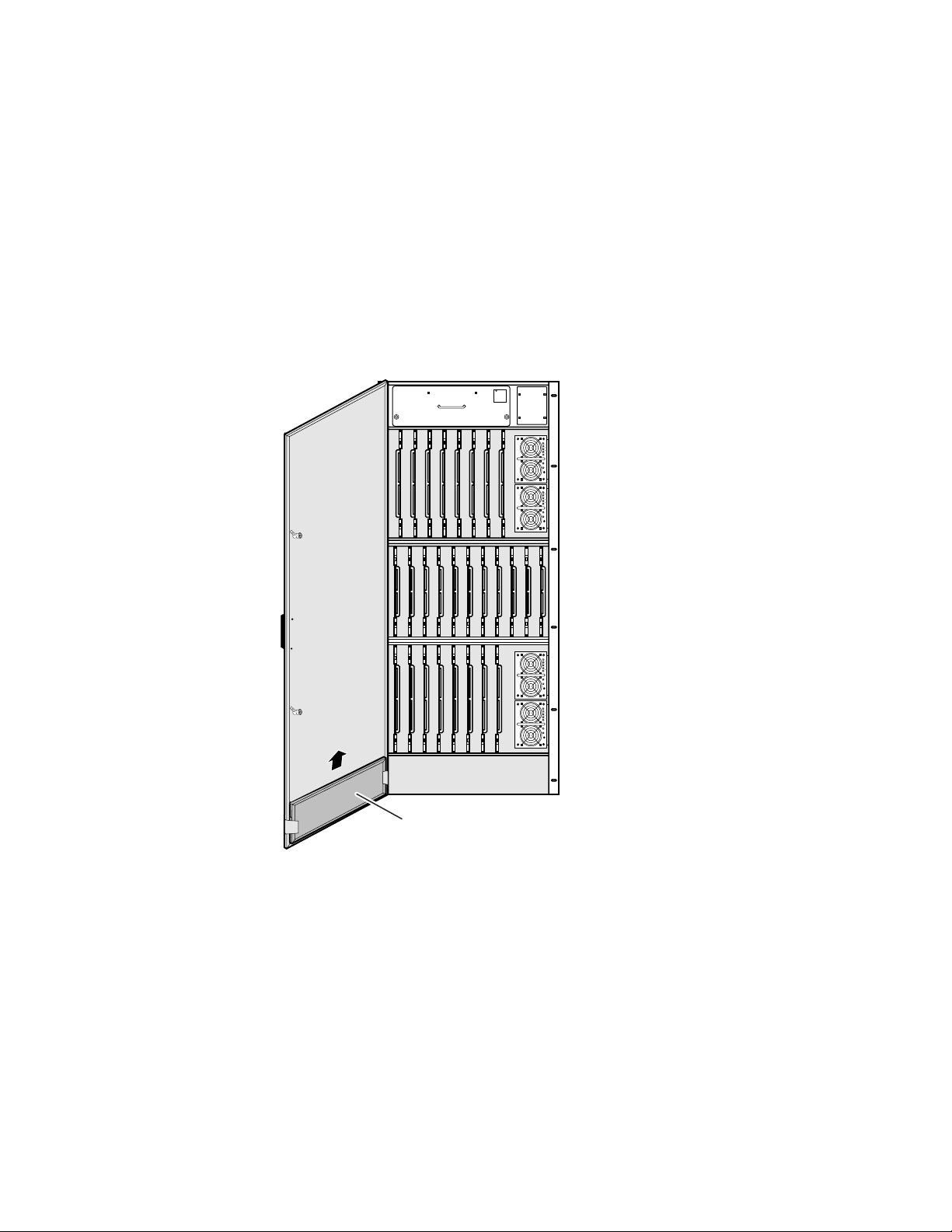
Section 5 — Maintenance and Troubleshooting
4. Close the ejector tabs. Replace the interconnect if removed, pin
alignment is critical.
CAUTION Multi-pin module connectors can become misaligned and cause damage to
the backplane and interconnect. Use caution when inserting modules. Do not
force modules into slots.
Air Filter 7500WB 256x256
The air filter slides in and out for easy replacement. Refer to Figure 5-1.
Figure 5-1. Filter Replacement
WARNING
ROTATING
FAN BLADES
PULL OUT
1/2 INCH
AND WAIT
30 SECONDS
BEFORE
REMOVING
100%
20 40 60 80
DCG
ACG
VADJ
100%
20 40 60 80
DCG
ACG
VADJ
Air Filter
Fan Assembly 7500WB 256x256
The Fan Assembly can be replaced as a complete unit.
To Replace a Fan
Refer to Figure 5-2.
1. Loosen the screws on the front of the fan assembly.
2. Pull the assembly out one half inch and wait for the fan blades to stop.
100%
20 40 60 80
DCG
ACG
VADJ
100%
20 40 60 80
DCG
ACG
VADJ
0528_01_01
5-2 7500 Series Instruction Manual
Page 65
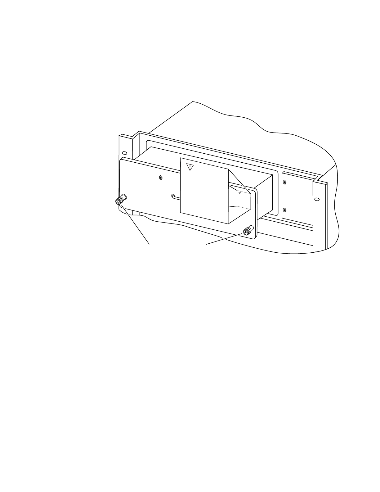
Service and Replacement Parts
3. Slide the fan assembly out of the frame.
4. Slide the new fan assembly into the frame.
5. Tighten the screws on the front of the fan assembly.
Figure 5-2. Fan Replacement
WARNING
ROTATING
FAN BLADES
PULL OUT
1/2 INCH
AND WAIT
30 SECONDS
BEFORE
REMOVING
W
A
R
N
IN
G
RO
TATIN
G
FAN
B
LADES
P
ULL OU
T
1/2 INCH
A
ND
W
AIT
30 SEC
ON
DS
BEFOR
E
REM
O
VING
Turn Screws to Release
Assembly from Frame
Service and Replacement Parts
Replacement parts can be ordered. Use the information on the back of the
title page to contact Customer Service. They will provide the current part
numbers, part availability, and ordering instructions.
Troubleshooting
Each module has LEDs, testpoints, and switches along its front edge which
are visible when the frame door is open. The LEDs indicate the operating
condition of the module. T estpoints are used to check voltages and gr ound.
Switches are used to reset the module. Testpoint and switch markings are
self-explanatory.
0528_01_03
7500 Series Instruction Manual 5-3
Page 66
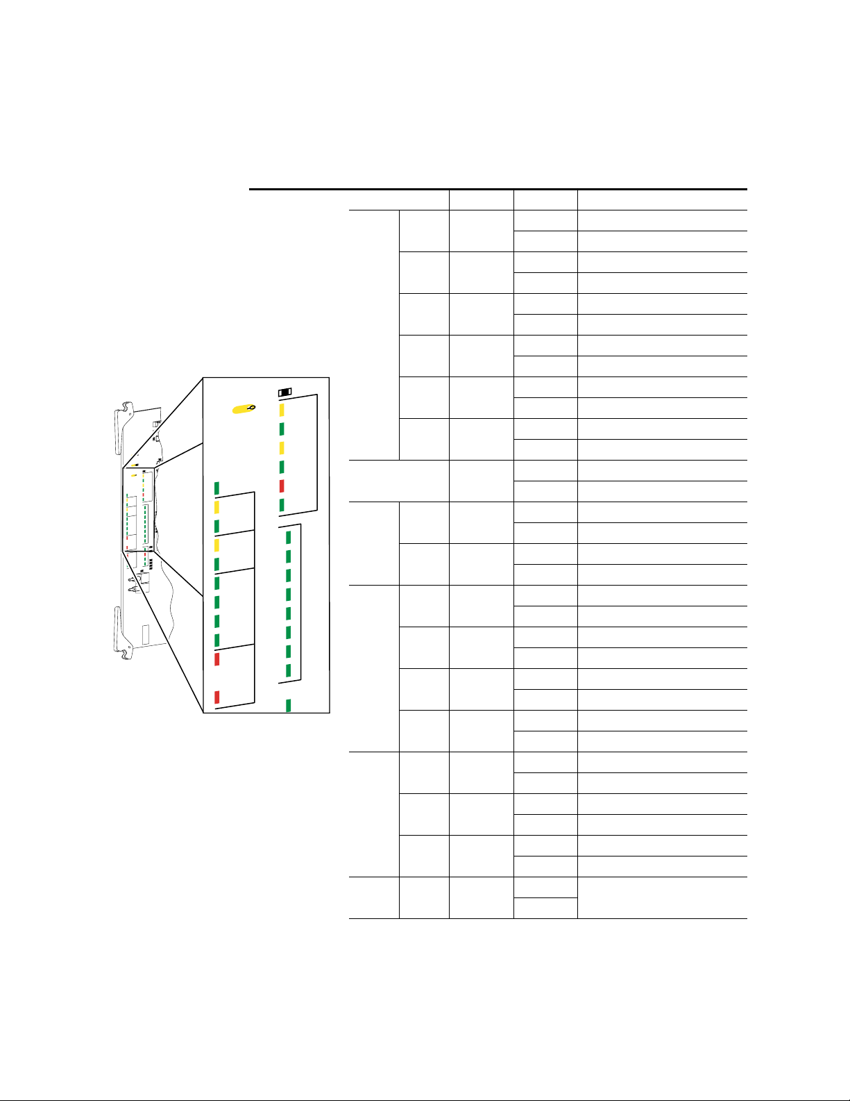
Section 5 — Maintenance and Troubleshooting
R
5
R
6
R
2
1
R
2
2
R
2
3
R
2
4
R
2
5
R
2
6
R
2
7
R
2
8
R
2
9
R
3
3
R
3
4
R
3
5
R
3
6
R
3
7
R
3
8
R
3
9
R
4
0
R
1
2
R
1
3
R
1
4
R
1
5
R
1
6
R
1
7
R
1
8
R
1
9
1
N
B
X
&
X
R
1
1
R
3
2
R
2
0
R
3
0
J
1
G
R
A
S
S
V
A
L
LE
Y
M
A
T
R
IX
C
O
N
T
R
O
LL
E
R
6
71-4
7
85–
J
2
1
R
E
S
E
T
C
L
E
A
R
M
E
M
R
3
T
E
S
T
I
D
L
A
B
E
L
G
O
E
S
H
E
R
E
C
1
9
9
0
3
L
T
C
4
9
1
C
S
R
4
1
+
5
V
R
1
+
3
.3
V
R
2
G
N
D
T
P
3
R
4
D
S
4
C
R
1
3
D
S
5
C
R
1
4
C
R
1
5
C
R
1
6
D
U
P
L
S
P
E
E
D
R
E
C
V
X
M
IT
C
O
L
L
L
IN
K
C
R
1
7
C
R
1
8
C
R
1
9
C
R
2
0
C
R
2
1
C
R
2
2
7
6
5
4
3
2
C
R
2
3
1
C
R
2
4
0
C
R
2
5
C
R
2
6
C
R
2
7
C
R
2
8
3
2
1
0
X
C
1
X
C
2
V
I
R
E
F
A
E
S
C
R
2
D
S
1
C
R
3
D
S
2
C
R
4
A
C
T
IV
E
R
E
C
V
X
M
IT
R
E
C
V
X
M
IT
C
R
5
C
R
6
C
R
7
C
R
8
C
R
9
C
R
1
0
T
C
P
R
E
S
R
E
F
1
P
R
E
S
R
E
F
2
P
R
E
S
R
E
F
E
R
R
O
R
4
8
K
1
P
R
E
S
4
8
K
2
P
R
E
S
C
R
1
1
4
8
K
E
R
R
O
R
C
R
1
2
D
S
3
S
Y
S
T
E
M
C
R
1
E
R
R
O
R
B
U
S
Y
P
W
R
O
K
N
B
X
T
E
S
T
E
T
H
E
R
N
E
T
C
2
U
2
M
C
T
O
O
A
P
O
G
8
2
1
R
7
R
8
R
9
R
1
0
Matrix Controller LEDs
The LEDs found on the Matrix Controller module are shown in Table 5-1.
Table 5-1. Matrix Controller LEDs
Group LED Indication Condition
DUPL
SPEED
RECV
DS4
(yellow)
CR13
(green)
DS5
(yellow)
Ethernet
XMIT
R4
CR2
DS1
CR3
DS2
CR4
CR5
CR6
CR7
CR8
CR9
CR10
CR11
GND
ACTIVE
RECV
IT
XM
RECV
XMIT
TC
PRES
REF1
PRES
REF2
PRES
REF
ERROR
48K1
PRES
48K2
PRES
48K
ERROR
TP3
XC1
XC2
VI REF
AES
DS4
CR13
DS5
CR14
CR15
CR16
CR17
CR18
CR19
CR20
CR21
CR22
CR23
CR24
CR2
DUPL
SPEED
RECV
IT
XM
COLL
LINK
7
6
5
4
3
2
1
0
3
ETHERNET
XC1
XC2
TEST
0531_01_04A_r3MC
VI REF
COLL
LINK
ACTIVE
RECV
&
XMIT
TC
PRES
REF1
PRES
REF2
PRES
REF
ERROR
48K1
PRES
AES
5-4 7500 Series Instruction Manual
TEST 0-7
48K2
PRES
48K
ERROR
CR14
(green)
CR15
(red)
CR16
(green)
CR2
(green)
DS1 & DS2
(yellow)
CR3 &CR4
(green)
CR5
(green)
CR6
(green)
CR7
(green)
CR8
(red)
CR9
(green)
CR10
(green)
CR11
(red)
CR17-CR24
(green)
On Ethernet-duplex half
Off Ethernet-duplex full
On Ethernet-speed 100BaseT
Off Ethernet-speed 10BaseT
On Ethernet-receiving
Off Not receiving
On Ethernet-transmitting
Off Not transmitting
On Ethernet-collision
Off Normal ethernet condition
On Ether-link
Off No Ether-link
On Normal - active control
Off Standby
On XC1 - receiving data
Off XC1 - not receiving data
On XC1 -Transmitting data
Off XC1 - not transmitting data
On VI REF-time code present
Off Not present
On VI REF-reference 1 present
Off Not present
On VI REF-reference 2 present
Off Not present
On VI REF-reference error
Off Normal
On Present
Off Not present
Present
Not present
On AES-48K error
Off Normal
On
Off
Not used - can be on or off
Page 67
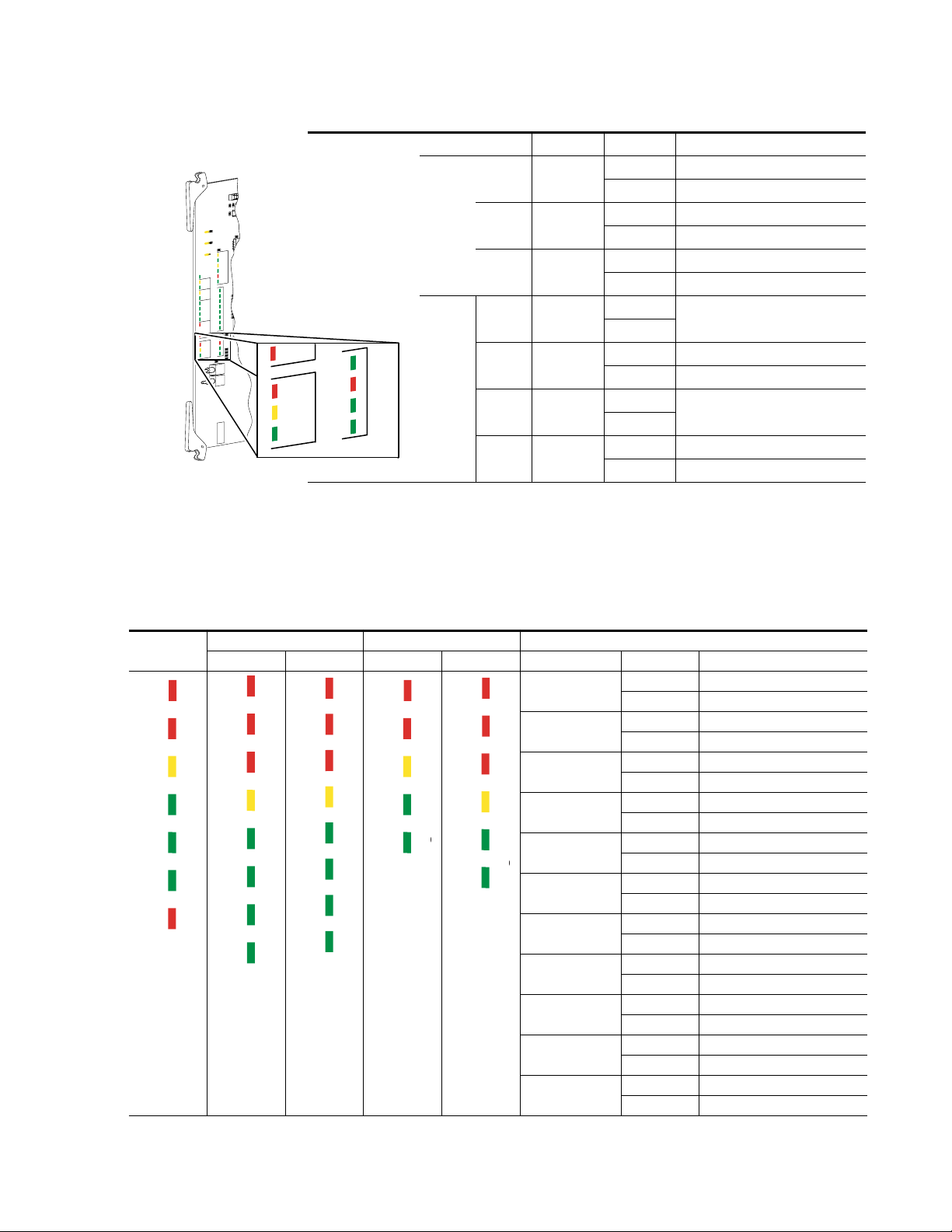
Table 5-1. Matrix Controller LEDs - (continued)
R
5
R
6
R
2
1
R
2
2
R
2
3
R
2
4
R
2
5
R
2
6
R
2
7
R
2
8
R
2
9
R
3
3
R
3
4
R
3
5
R
3
6
R
3
7
R
3
8
R
3
9
R
4
0
R
1
2
R
1
3
R
1
4
R
1
5
R
1
6
R
1
7
R
1
8
R
1
9
1
N
B
X
&
X
R
1
1
R
3
2
R
2
0
R
3
0
J
1
G
R
A
S
S
V
A
L
L
E
Y
M
A
T
R
IX
C
O
N
T
R
O
L
LE
R
6
7
1
-4
7
85
–
J
2
1
R
E
S
E
T
C
L
E
A
R
M
E
M
R
3
T
E
S
T
ID
L
A
B
E
L
G
O
E
S
H
E
R
E
C
1
9
9
0
3
L
T
C
4
9
1
C
S
R
4
1
+
5
V
R
1
+
3
.3
V
R
2
G
N
D
T
P
3
R
4
D
S
4
C
R
1
3
D
S
5
C
R
1
4
C
R
1
5
C
R
1
6
D
U
P
L
S
P
E
E
D
R
E
C
V
X
M
IT
C
O
L
L
L
IN
K
C
R
1
7
C
R
1
8
C
R
1
9
C
R
2
0
C
R
2
1
C
R
2
2
7
6
5
4
3
2
C
R
2
3
1
C
R
2
4
0
C
R
2
5
C
R
2
6
C
R
2
7
C
R
2
8
3
2
1
0
X
C
1
X
C
2
V
I
R
E
F
A
E
S
C
R
2
D
S
1
C
R
3
D
S
2
C
R
4
A
C
T
IV
E
R
E
C
V
X
M
IT
R
E
C
V
X
M
IT
C
R
5
C
R
6
C
R
7
C
R
8
C
R
9
C
R
1
0
T
C
P
R
E
S
R
E
F
1
P
R
E
S
R
E
F
2
P
R
E
S
R
E
F
E
R
R
O
R
4
8
K
1
P
R
E
S
4
8
K
2
P
R
E
S
C
R
1
1
4
8
K
E
R
R
O
R
C
R
1
2
D
S
3
S
Y
S
T
E
M
C
R
1
E
R
R
O
R
B
U
S
Y
P
W
R
O
K
N
B
X
T
E
S
T
E
T
H
E
R
N
E
T
C
2
U
2
M
C
T
O
O
A
P
O
G
8
2
1
R
7
R
8
R
9
R
1
0
g
g
Group LED Indication Condition
Activity
and
Power
CR11
CR12
DS3
CR1
48K
ERROR
ERROR
BUSY
R
PW
OK
SYSTEM
CR25
CR26
CR27
CR28
3
NBX
2
1
NBX
0531_01_04_r3MC
(Node
Bus
Control)
0
ERR
BSY
PWR
CR25
CR26
CR27
CR28
DS7
(red)
DS8
(yellow)
DS9
(green)
3
(green)
2
(red)
1
(green)
0
(green)
Troubleshooting
On Circuit failure or reset
Off Normal
On Active Controller indication
Off Inactive
On Power on
Off Bad or unseated module
On
Off
On Processor Event
Off Normal
On
Off
On Node Controller okay (health check)
Off Bad or unseated module
Not used - can be on or off
Not used - can be on or off
Matrix Modules
7500NB LEDs are identified in Table 5-2 and 7500 WB LEDs in
Table 5-3.
Table 5-2. 7500NB Modules LEDs
Crosspoint
ERROR
PAR
ERROR BUSY PWR DONE DIAGVI
STB
7500 Series Instruction Manual 5-5
AES (Synchronous) Digital (Asynchronous) LEDs
Input Output Input Output Label Indication Condition
ERROR
DIAG
PAR
ERROR BUSY
PWR DONE
REF1 REF2
OVER
TEMP
ERROR
PAR
ERROR BUSY
PWR DONE
STB
VI
AUD
REF
ERROR
PAR
ERROR BUSY PWR DONE
OVER
TEMP
ERROR
PAR
ERROR BUSY PWR DONE
PAR ERR or PAR
(red)
ERR or ERROR
(red)
BSY or BUSY
(yellow)
PWR
(green)
DONE
(green)
VI STB
(green)
DIAG
(red)
REF1
(green)
REF2
(green)
OVER TMP
(green)
AUD REF
(green)
On Parity error
Off Normal
On Error.
Off Normal
On Busy
Off Standby
On Power on
Off Bad or unseated module
On Done
Off Standby
On VI Strobe present
Off No VI Strobe
On Diagnostic in process
Off Normal
On Reference 1 present
Off No Reference 1
On Reference 2 present
Off No Reference 2
On Over temperature
Off Normal
On Audio Reference present
Off No Audio Reference
Page 68
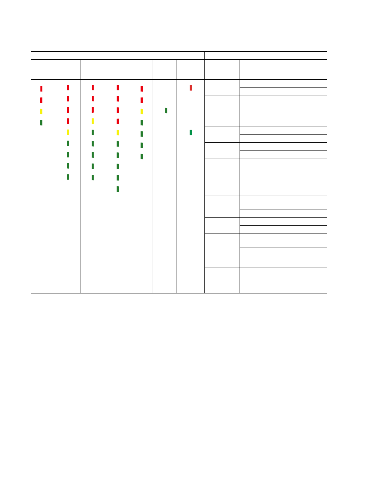
Section 5 — Maintenance and Troubleshooting
Table 5-3. 7500WB Modules LEDs
Module LEDs
Input
ERROR
PARITY
ERROR BUSY
POWER
OK
a
Either VI STROBE 1 or VI STROBE 2 needs to on for proper timed switching.
Output &
Expansion
Switch
DIAG
0531_01_4_r0WBINPUT
OVER
TEMP
ERROR
PARITY
ERROR BUSY
POWER
OK
0531_01_1_r0WBOUTPUT
DONE
STROBE
VI
1
STROBE
VI
2
64x64 128x64 Monitor DC
DIAG
ERROR
PARITY
ERROR BUSY
POWER
OK
DONE
STB1
VI
STB2
VI
ENABLE
BOARD
DIAG
OVER
TEMP
ERROR
PARITY
ERROR BUSY
0531_01_2A_r0WBCROSSPOINT
POWER
OK
DONE
STROBE
VI
1
STROBE
VI
2
ENABLE
BOARD
ERROR
PARITY
ERROR BUSY
PRESENT
BATTERY
POWER
0531_01_3_r0WBMONITOR
OK
DONE
STROBE
VI
1
0531_01_2_r0WBCROSSPOINT
STROBE
VI
2
EXTERNAL
Expansion
Bypass
0531_01_3_r0DCDIST
OVER
TEMP
0531_01_18_r0
POWER
OK
Label Indication Condition
PARITY ERROR
(red)
ERROR
(red)
BUSY
(yellow)
POWER OK
(green)
DONE
(green)
DIAG
(red)
VI STROBE 1
(green)
VI STROBE 2
(green)
OVER TMP
(red)
BOARD ENABLE
(green)
On Parity error
Off Normal
On Error.
Off Normal
On Busy
Off Standby
On Power on
Off Bad or unseated module
On Firmware loaded okay
Off Firmware load problem
On Diagnostic mode
Off Normal
On
Vertical Interval Strobe 1
a
present
Off No Vertical Interval Strobe 1
On
Vertical Interval Strobe 2
present
Off No Vertical Interval Strobe 2
On Over temperature
Off Normal
On
Module is communicating
with the Controller module
Module is not communicatOff
ing with the Controller mod-
ule
EXTERNAL
On DC Battery is connected
BATTERY
PRESENT
Off DC Battery is not connected.
(green)
5-6 7500 Series Instruction Manual
Page 69
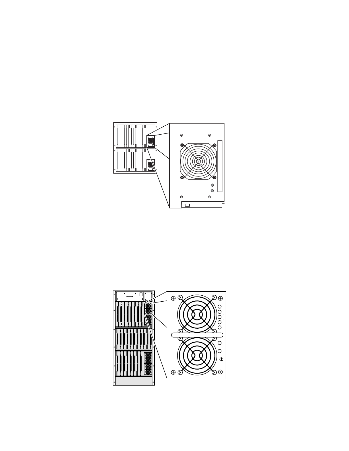
Power Supply Modules
7500NB Power Supply Module
The 7500NB Power Supply module is a fully autoranging 400 W 48V DC
Output module. LED indicators:
DC power when Illuminated),
present when illuminated). See Figure 5-4.
Figure 5-3. 7500NB Power Supply Module
Troubleshooting
DC OK (green light indicates satisfactory
AC PRESENT (yellow light indicates AC power
0528_01_19
DC OK
AC PRESENT
7500WB Power Supply Module
The 7500WB Power Supply module is a fully autoranging 1000 W 48V DC
Output module. LED indicators:
power when Illuminated),
when illuminated), and the rest of the LEDs show percentage of available
power usage. See Figure 5-4.
Figure 5-4. 7500WB Power Supply Module
WARNING
ROTATING
FAN BLADES
PULL OUT
1/2 INCH
AND WAIT
30 SECONDS
BEFORE
REMOVING
100%
2040 60 80
DCG
ACG
VADJ
100%
2040 60 80
DCG
ACG
VADJ
100%
2040 60 80
DCG
ACG
VADJ
100%
2040 60 80
DCG
ACG
VADJ
Latch
ACG (green light indicates satisfactory DC
DCG (green light indicates AC power present
100%
DCG
ACG 20 40 60 80
VADJ
0528_01_20
7500 Series Instruction Manual 5-7
Page 70
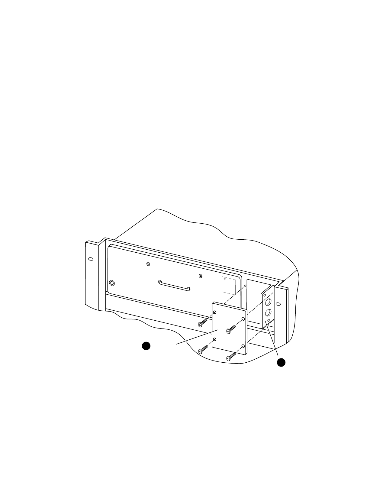
Section 5 — Maintenance and Troubleshooting
W
A
R
N
IN
G
RO
TA
TING
FA
N
B
LA
D
ES
PULL O
U
T
1/2 INC
H
A
N
D W
A
IT
30 S
EC
O
N
DS
BEF
O
RE
RE
M
O
VIN
G
Thermal Control Module Reset 7500WB 256x256
The Thermal Control module monitors the temperature inside the matrix.
It controls fan speed and will shutdown the matrix if a critical temperature
condition occurs (temperature in excess of 80° C, 176° F). This is a fail-safe
feature. If a shutdown does occur all modules within the matrix should be
inspected. Once the cause of the critical temperature condition has been
identified and corrected, the Thermal Control module must be reset. Refer
to Figure 5-5.
To Reset the Thermal Control Module
1. Remove cover screws. Set cover aside.
2. Slide the module out at least one half inch to unseat the module.
3. Reseat the module into the frame.
4. Replace cover and secure with screws.
Figure 5-5. Thermal Control Module Reset
Remove
1
Cover Plate
Unseat Module
2
≥ 0.5 in. (13mm)
0528_01_02
Note The Thermal Control module can also be reset by removal and replacement
of all Power Supplies or unplugging and replugging the power cords.
5-8 7500 Series Instruction Manual
Page 71
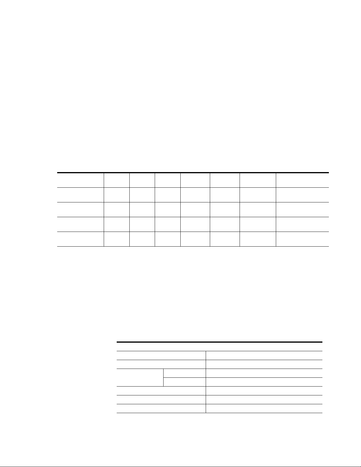
Appendix — Specifications
Mechanical and Power Specifications
Table A-1. 7500 Mechanical and Power Specifications Maximum Configuration
Power Consumption
(Maximum)
120 W
300 W
900 W
1800 W
19 in.
19 in.
19 in.
19 in.
a
Width Height Weight Rack Units Voltage Input
483 mm
19 in.
483 mm
19 in.
483 mm
19 in.
483 mm
19 in.
534 mm
21 in.
1067 mm
42 in.
578 mm
22.72 in.
1110 mm
43.72 in.
Component Depth
7500NB256X256B/D 483 mm
7500NB512x512B/D 483 mm
7500WB128x128 483 mm
7500WB256x256 483 mm
a
Allow a minimum of four inches behind the frames for cabling
46.7 kg.
103 lbs.
104.3 kg.
230 lbs.
47.6 kg.
105 lbs.
81.7 kg.
180 lbs.
12
24
13
25
100-240 V AC or
36-60 V DC
100-240 V AC or
36-60 V DC
100-240 V AC or
40-56 V DC
100-240 V AC or
40-56 V DC
Performance and Environmental Specifications
7500NB
Table A-2. 7500NB256x256 and 512x512
AES Inputs
Signal Format SMPTE-276-M (AES/EBU)
Input Voltage 200 mV to 5V p-p
Impedance/Connector BNC unbalanced 75 Ohms
50-pin D balanced 110 Ohms
Return Loss >15dB 0.1-1 MHz 25dB @ MHz
Cable EQ None
Jitter Tolerance +/- 1/2 UI
7500 Series Instruction Manual A-1
Page 72
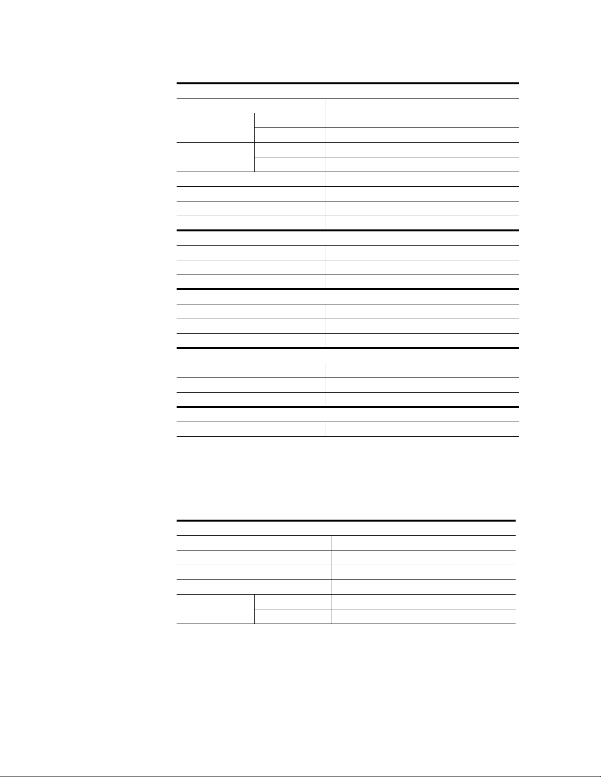
Appendix — Specifications
Table A-2. 7500NB256x256 and 512x512 - (continued)
AES Outputs - Including Monitors
Signal Format SMPTE-276-M (AES/EBU)
Output Voltage Balanced 1V p-p
Unbalanced 4V p-p
Impedance/Connector BNC unbalanced 75 Ohms
50-pin D balanced 110 Ohms
Rise-time 15-30 ns
Return Loss >15dB 0.1-1 MHz 25dB @ MHz
Input-to-Output Delay 3-4 AES Frames
Output Jitter TBD
Reference Video Input
Type NTSC or PAL color black
Impedance/Connector High/looping BNC
Return Loss >25dB 0.1-5 MHz, 75 ohm termination
Audio Reference Inputs 1 and 2
Type SMPTE-276-M (AES/EBU) audio black not necessary
Impedance/Connector High/looping BNC
Return Loss >15dB 0.1-6 MHz, 75 ohm termination
Node Bus Input
Type SMS-7000 Node Bus proprietary Global Serial Channel
Impedance/Connector High/looping BNC
Return Loss >25dB @ 1 MHz, 75 ohm termination
Environment
Operating Temperature 0-to-40 degrees C
7500WB
Table A-3. 7500WB128x128 and 256x256
Video Inputs
Format SMPTE-259, SMPTE-292
Voltage 800 mV ± 10%
Impedance / Connector 75 ohms, unbalanced BNC
Return Loss > 15 dB 1 MHz ≥ 1.5 GHz, self terminating, 20 dB typical
Cable Equalization 1694A 100 meters maximum all formats
7731A 200 meters maximum all formats
A-2 7500 Series Instruction Manual
Page 73
Performance and Environmental Specifications
Table A-3. 7500WB128x128 and 256x256 - (continued)
Video Outputs (including monitors)
Format SMPTE-259, SMPTE-292
Voltage 800 mV ± 10%
Rise time SMPTE-292 R AC
Impedance / Connector 75 ohms unbalanced BNC
Return Loss > 15 dB 1 MHz -> 1.5 GHz, self terminating, typical
Output Jitter (reclocked) < 0.2 unit interval
Output Reclocking 143 Mbps, 177 Mbps, 270 Mbps, 360 Mbps, 540 Mbps,
Output Non-reclocking Bypass 10 Mbps ≥ 500 Mbps
Input To Output Delay 28 nanoseconds ± 2 nanoseconds
Input To Output Delay Match ± 5 nanoseconds
Video Reference 1 & 2 Input
Type NTSC or PAL color black
Impedance / Connector High looping BNC
Return Loss > 25 dB @ 1 MHz, when terminated into 75 Ohms
Vertical Interval Switch
VI1, Video Reference 1 525/625 Mode Middle of the line ± 5 microseconds - 0, + 0, field latency
Pulse Mode 2 microseconds or less from rising edge, - 0, + 1 field
VI1, Video Reference 2
Using SMS 7000
Control System
Impedance / Connector High looping BNC
Return Loss > 25 dB @ 1 MHz, when terminated into 75 ohms
Node Bus Input
Type SMS7000 Node Bus proprietary Global Serial Channel
Impedance / Connector High, looping BNC
Return Loss > 10 dB @ 1 MHz, when terminated into 75 ohms
Ethernet Port
Connector RJ45
Power Supply
Mains AC Voltage 100-240 V 50/60 Hz
AC Current 128x128 100-120 V 8 amps maximum
DC Voltage 48 V DC nominal (40-56 V DC)
DC Current 128x128 22 amps DC nominal @ 48 V in
525/625 Mode Middle of the line ± 12 microseconds - 0, + 0, field
Pulse Mode - 5.5 + 7.5 microseconds or less from rising edge, - 0, +
200-240 V 4 amps maximum
256x256 100-120 V 16 amps maximum
200-240 V 8 amps maximum
256x256 33 amps DC nominal @ 48 V in
1.485 Gbps
latency
latency
1 field latency
7500 Series Instruction Manual A-3
Page 74

Appendix — Specifications
Table A-3. 7500WB128x128 and 256x256 - (continued)
Environmental
Operating Temperature 0-40 degrees C (32-104 degrees F)
Operating Humidity 10-90% non-condensing
Static Withstand 1.5 k V (330 ohms, 150 pF)
A-4 7500 Series Instruction Manual
Page 75

Glossary
AES
Audio Engineering Society. AES represents
any of the digital audio standards established by the Audio Engineering Society.
AES/EBU
Name for a digital audio standards established jointly by the Audio Engineering Society and European Broadcasting Union. The
sampling frequencies for this standard vary
depending on the format being used.
Alarm
A signal indicating major or minor alarm
conditions.
Alien Matrices
Any matrix which is not a part of the Series
7000 router product line.
All-level Takes
Switch the same input number on all Levels,
to the controlled Destination.
Amezi
Asynchronous Mezzanine board. An RS422/RS-232 communications board which
mounts on the 7000 MCPU or a 7000 Communications Interface (CIF) module and provides RS-422 and RS-232 ports. The
Asynchronous Mezzanine board is one of
several mezzanine boards of differing functionality.
ANC
Active Node Controller. An ANC is communicating with the MCPU and will appear in a
list of Active Node Controllers when polled
by the GUI. The Enhanced Node Controller
and the Matrix Controller modules also appear in the list. ANCs include both the primary and backup Controller modules.
ANSI
American National Standards Institute.
Assignment
Assignment is an action that grants permission for exclusive control of a resource. Multiple devices may be assigned permission for
exclusive control of a single device, however
only one may exercise control at a specific
point in time.
Control of particular sources and TieLines
can be Assigned to destinations on a case-bycase basis. The Assignment system is enabled (Machine and TieLine Assignment)
through the GUI Enables menu. Active Assignments are controlled through the GUI
(on-line, OnLine menu, Assignments submenu) or may be handled by an external automation or scheduling system.
Backplane (Rear connector channel, Motherboard)
The circuit board at the back of an electronics
frame where modules (from the front) and
cables (from the rear) are plugged-in.
BNC
Bayonet Neill-Concelman (BNC) connector.
(Named for its inventors). A type of coaxial
cable connector.
BPI
Backplane Interface. This is required for a
Communications Interface module to communicate with a MCPU module.
BPS
Button Per Source. Name given to a panel
feature that performs a source take with the
single push of a button.
7500 Series Instruction Manual Glossary-1
Page 76

Breakaway
Coaxial Cable (coax)
A Take operation which is performed by accessing the control Levels of a Destination individually and selecting a different Source
on at least one Level than that selected on the
others. Breakaways allow a Destination to selectively utilize video and audio from different Sources.
BSY
Busy. This is commonly found on the modules to identify the yellow busy LED.
Bus
A signal path to which a number of inputs
may be connected to feed one or more outputs. Also, a signal path used to communicate between devices such as the node bus or
the Control Panel bus. the node bus is used to
communicate between the MCPU and the
Controller modules. The Control Panel bus is
used to communicate between the MCPU
and Control Panels.
Chop
A variation of a Take command that alternately connects each of two different Sources
to a single Destination (flip-flopping) at a
designated switching rate (the chop rate).
CIF
Communication Interface. A Series 7000 optional CIF module is a general purpose communications interface module used to
augment the capability of the Series 7000
MCPU when the MCPU is housed in a standalone Control Frame. Each CIF module will
support four mezzanine submodules; mezzanine submodules in turn provide a particular communications capability.
A cable which has a metallic noise shield surrounding a signal-carrying conductor. In
video, the cable impedance is typically 75
ohms. Ethernet coax is typically 50Ω impedance.
Cold Start
A boot from power off.
Component Video
The un-encoded output of a camera, videotape recorder, etc., consisting of 3 primary
color signals: Red, Green, and Blue (RGB)
that together convey all necessary picture information. In some component video formats, these three components have been
translated into a luminance signal and two
color difference signals, e.g. Y, R-Y, B-Y.
Composite Video
An encoded video signal, such as NTSC or
PAL video, that includes horizontal and vertical synchronizing information.
Control Device
Panel, computer, or other device that controls router crosspoint selections.
Control Panel Bus (CP bus)
Communications path between control panels or devices and the MCPU which controls
the routing matrices.
Controllers
Part of the control system, Controllers are cir cuit modules which interface between the
MCPU and signal processing modules.
COS
CLN
Client Control Panel. A companion panel
used with the Server panel to expand Source
and Destination selection. Each Client controls three Destinations.
Glossary-2 7500 Series Instruction Manual
Cubicle or Studio. A custom configuration
set.
CPO
Clear Protected Output.
Page 77

Crosspoint (XPT)
EC I/F
An electronic switch that allows a signal to
pass from an input to an output when the
switch is closed.
DA
Distribution Amplifier. The Series 7000 uses
DAs to expand outputs.
Data Matrix
A signal processing matrix containing modules that route RS-422 or RS-485 data.
Default
The setup condition existing when a device
is first powered-up or after a system restart.
Destination (DEST or DST)
The point to which Source signals are routed. In Series 7000, a Destination may include
one or more outputs, across multiple Levels,
with any connector number offset (user-defined in system configuration). (See Multilevel Switching in Section 1.)
Destination Exclusion Set (DXS)
User-determined set of Destinations excluded from control by a particular panel. If used,
Destination Exclusion Sets are included in a
Panel Template before the template is downloaded to a particular control panel. A specific Destination Exclusion Set may be shared
by more than one panel template.
DGND
Digital Ground.
External Control Interface.
EDP
Eight Destination Paging control panel.
EMI
Electromagnetic interference.
ENC
Enhanced Node Controller. Designed to replace the Node Controller it can be used in all
Classic and DV Series matrices. The ENC is
required for Dual Control of a matrix by the
Series 7000 Control System and an external
device such as a PC. The ENC does not support the Kscope Interface Mezzanine.
EPROM
Erasable Programmable Read Only Memory .
EPROMs are non-volatile memory chips.
They are commonly called Flash memory
chips.
ERR
Error. This is commonly found on the modules to identify the red error LED.
Ethernet
A local area network (LAN) technology capable of transmitting information between
computers at speeds of 10 and 100 Mbps.
Exclusion
User-determined Sources excluded from
routing to a particular Destination.
DST
See Destination (DEST or DST).
DSVOM
Dual Sync Video Output Monitor. Part of the
DV Series.
FC
Frame Controller.
FET
Field Effect Transistor.
First Come First Served (FCFS)
Dumb Terminal
A conversational slave to a host computer.
7500 Series Instruction Manual Glossary-3
Tieline status wher e it is not necessary to create a reservation to use the specified Tieline.
Page 78

Flag
Hardware
A parameter that can be set in a control panel
template to control how the panel operates.
Flash Memory
See: EPROM.
Flip-Flopping
Alternately connecting each of two different
Sources to a single Destination (at a designated switching rate (See: Chop).
GBR (Green, Blue & Red)
The three primary colors used in video processing, often referring to the three un-encoded outputs of a color camera. The
sequence of GBR indicates the mechanical
sequence of the connectors in the SMPTE
standard. Also see: RGB.
GPI
General Purpose Interface. Refers to the HXGPI or Horizon General Purpose Interface
used to connect a Horizon Routing Switcher
to a Series 7000 System.
GSC
Global Serial Channel. Refers to the GSC
Mezzanine which provides additional BNC,
serial communications ports for the Series
7000 MCPU. The four additional BNCs provided per mezzanine can be used as additional control panel bus or Tally System
ports. The GSC can also be used to provide
Node Control Bus expansion. In this capacity, only one of the four BNCs can be used because traffic density is too great for all four
BNCs to be serviced by a single communications controller.
1. Electrical devices connected through physical wiring. 2. Electronic programming technique using physical connections and
therefore essentially unalterable.
HDTV
Television with a resolution approximately
four times that of Conventional Definition
Television and a 16:9 (H x V) picture aspect
ratio.
Heartbeat
A health status message provided by networked frames that are polled by MCPUs.
Horizon
A Grass Valley line of routing switchers.
HX
Grass Valley Horizon Series Crosspoint
Routing System.
IBOP
Interconnect /Break Out Panel. An option
panel used to add BNC connectors to an audio matrix using 50-pin D connectors.
ID or IDENT
A software routine that identifies a device
(e.g. a control panel). Includes such information as:
• controlled Destination
• active tally level
• panel name
• software version
• system name
I/O
GUI
Graphical User Interface. Refers to the Configuration Editor software program used to
configure the Series 7000 System.
Glossary-4 7500 Series Instruction Manual
Abbreviation for input/output. Typically refers to sending information or data signals to
and from devices.
Page 79

Input
LED
A single physical, numerically designated
connection point of an in-coming signal to a
matrix. One or more Series 7000 inputs can
be assigned to a Source name during System
Configuration.
Input Offset
Unlike traditional multi-level systems, Series
7000 Sources do not have to use the same input connector number on each matrix Level
(i.e. RGB inputs for one Source can use input
#1 in one matrix for R, input #4 in another
matrix for G, etc.) The offset of the input
numbers used is logged in the System Configuration.
J Number
Jack Number.
Jumper
A short conductor used to manually bridge
two contact points. Used in Series 7000
Alarm system. Also called a strap.
Light emitting Diode. In Grass Valley products, LEDs illuminate to indicate a specific
state (such as normal, error, on-line, and so
on).
Level
Level is a name given to a group of signals
that have something in common such as video, audio right, audio left, R, G, or B. This
grouping becomes an independently controllable stratum of signals or crosspoints
within a Physical Matrix or routing system.
A Level may include more than one Virtual
matrix as a slaved set. All elements in a Level
respond to commands addressed to that Level.
Local
Local is used during configuration to identify local Sources and Destinations. Local
Sources and Destinations are inputs and outputs physically connected to the Series 7000
System using the related configuration file.
Kadenza
A Grass Valley Group digital video effects
system that can be used in an integrated environment with the Series 7000.
Kaleidoscope
A Grass Valley Group digital video effects
system that can be used in an integrated environment with the Series 7000.
KISS
Key Input Source Select. Used in configuring
the Kscope Key Sources.
KScope
The collective name for Kadenza and Kaleidoscope.
Krystal
A Grass Valley Group digital video effects
system.
Master
A module that controls a subordinate (slave)
module.
Matrices
Plural of matrix.
Matrix
A configuration of potentially intersecting
inputs and outputs. In routing switchers, signal switching hardware configured such that
any input may be switched to any output.
MB4
Programmable Multibus 4 Control Panel.
MB8
Programmable Multibus 8 Control Panel.
MC
Matrix Controller . Controller module used in
7500 Series matrices.
7500 Series Instruction Manual Glossary-5
Page 80

MCO
Mezzanine
Machine Control Only Control Panel.
MCPU
Master Control Processing Unit. This module provides:
• Overall system control
• Node manager interface to Series 7000
matrices
• Direct control panel support for up to 64
control panels
• Programmable real-time clock, date and
time stamping for logged events
• Redundant controller interface (allows
primary and backup MCPU pairs)
• Static RAM sizes (ranging from 128k bytes
to 4M bytes) are supported
• Flash ROM sizes (ranging from 128k bytes
to 4M bytes) are supported
MEC
Matrix Element Control. The MEC bus connects the control circuits of the various matrix modules in a frame section to the Node
Controller. In some cases, when the MCPU
and Node Controller reside in the same
frame, these connections are all internal to
the frame. More often, there are multiple
Node Controllers in a system and a coaxial
cable is run between Node Bus ports of each
frame in the system. Only secondary systems
and a particular compact configuration run
external MEC buses.
A secondary printed circuit module consisting of a flat circuit board of insulating material with conductive circuits etched on and/
or components mounted on its surface.
These submodules generally plug into a primary module. Sometimes referred to as a
submodule or daughter board.
Module
A single circuit board or assembly of circuit
boards that can be readily removed from an
electronics frame without first having to remove screws or other mounting hardware.
Multiformat
Ability to pass multiple signal types, such as
serial digital, analog component, and analog
composite.
Name(s)
Sources, Destinations, Levels, Salvos, Control Panels, Node Controllers, MCPUs, Mezzanine Boards, Tally Modules, and other
components of the Series 7000 system all
have names. When system software sets out
to perform a function, a Take for instance, it
looks for the source name, determines the inputs involved, and Takes the Source to the
Destination specified (by name). Naming
conventions are discussed in Section 1 of the
Configuration manual. Names are important
to operation and equally so to configuration.
NB (Node Bus)
Node Bus. A name for the communications
bus between the MCPU and Controllers.
MEDIC
Matrix Element Decode Integrated Circuit.
Used as a communications bus between the
MCPU and Controllers.
Glossary-6 7500 Series Instruction Manual
NB (Narrow Band)
Identifies the 7500 Series AES Audio Matrices.
Page 81

NC
Panel Template
Node Controller. Controller used by Classic
and DV Series matrices. The controller collects information from the modules in a matrix, sends the information to the system
MCPU, and receives instructions from the
MCPU.
Node Controller
See NC.
NTSC
Standard for scanning television signals.
Used in the U.S., Canada, and Japan.
Output
A single physical, numerically designated
connection point of an out-going signal from
a matrix. One or more Series 7000 outputs
can be assigned to a Destination name during System Configuration.
P32
32 Button-per-source Control Panel.
Configuration data specifying control panel
configuration; which includes items such as
Tally Level, Destination, button assignments,
and Flags restricting or allowing certain actions. Completed templates are downloaded
to specific control panels.
Physical Matrix
Defines the total Input/Output size of a like
signal type matrix. A Physical Matrix may be
sized from 16x16 to 1,024x1,024 in increments of 16. Physical Matrices may be used
to unite discrete frames in a large matrix or to
fragment a single frame into smaller matrices. Every system must have at least one
Physical Matrix and one Controller slice.
PLD
Programmable Logic Device.
Port
A connector, usually bidirectional, through
which one device communicates with others.
P48
48 Button-per-source Control Panel.
PAL
Standard for scanning television signals.
Used in most European countries.
Panel Prefixes
A set of 1-to-8 printable ASCII character
strings assigned to the 16-button or 24-button keypads on control panels. Used with
suffixes to comprise a complete Source or
Destination name. (Prefixes and 1-character
suffixes are assigned to panel Keypad sets.)
Panel Suffix Set
A set of single printable ASCII characters
usually the numbers 0-9 assigned to 10 buttons of a control panel 16-button or 24-button
keypad. Pre-configured defaults exist for
Telephone and Calculator style suffix sets.
Preset
Selecting a Source in preparation to taking it
to air; a tentative change to one or more crosspoints which has not yet been executed.
Protect (PROT)
A control function which prevents control
panels or devices from changing the current
Source selection for the specified Destination.
PROTOVRD
Protect Override.
PWR
Power. This is commonly found on the modules to identify the green power LED.
PXD
X-Y Destination Control Panel.
7500 Series Instruction Manual Glossary-7
Page 82

PXS
Remote
Programmable X-Y Source Control Panel.
PXY
Programmable X-Y. Used to identify a group
of control panels consisting of a PXS, and one
or more PXYE and PXD panels.
PXYE
Programmable X-Y Expansion Control Panel.
Rack
An equipment rack. A standard EIA equipment rack is 19 inches (48.26 am) wide.
Rack Unit (RU)
Unit of measure of vertical space in an equipment rack. One rack unit is equal to 1.75 inches (445 mm). The height of a GVG electronics
frame is typically specified in rack units.
RAM
Random access memory.
RAS
Remote Access Service.
Remote is used during configuration to identify remote Sources and Destinations. Remote Sources and Destinations are inputs
and outputs not physically connected to the
Series 7000 System using the related configuration file. These remote Sources and Destinations are controlled over a network.
Reserved
Tieline status wher e a reservation is requir ed
to use a specified Tieline. See First Come First
Served (FCFS).
Reset
See reboot.
Resource Group
A resource group is an association of machine control devices all within a single work
area.
RGB (Red, Green & Blue)
The three primary colors used in video processing, often referring to the three un-encoded outputs of a color camera. See GBR
(Green, Blue & Red).
Rear Connector Channel
ROM
See Backplane (Rear connector channel, Mother-
board).
Reboot (Reset)
To restart a computer, reloading the software.
Redundant Power Supply
Backup power supply which takes over immediately if the primary power supply fails.
Glossary-8 7500 Series Instruction Manual
Read Only Memory.
Room
A group of Destinations (usually a physical
studio or control room within a facility) to
which machine control and tally assignments can be made by an automated facility
control system or the GUI Assignments
menu. An assignment made to one Destination in a room allows control by any of the
Destinations in that room.
Page 83

RP
SCP
Rear Panel. RPs are special connector channels that support the various mezzanine
boards. They are attached to the back of the
stand-alone Control Frame according to
which mezzanines are on the associated CIF
module.
RS-232 or RS-232C
A serial data communications standard. RS232C is a low-speed serial interface which
uses a single-ended (unbalanced) interconnection scheme. Commonly used in telecommunications to connect computers and
terminals to modems and other devices. The
C suffix refers to the version of the RS-232
standard.
RS-485
A high-speed serial interface connection between data communications equipment. RS485 specifies the characteristics of a balanced
(differential) multipoint transceiver/receiver
interface.
Simple Control Panel.
SDP
Single Destination Paging control panel.
SDV
Serial Digital Video.
SERIM
Serial Interface Module.
SID
Source Identification panel.
Slave
Component in a system that does not act independently, but only under the control of
another component.
Slice
A group of inputs and outputs assigned to a
Controller.
RU
Rack Unit. See Rack Unit (RU).
Salvo (SVO)
A named, system-wide Preset which, when
executed, may change crosspoints on one or
more Destinations at the same time.
Salvo Elements
The individual take commands (Source to
Destination connections) which comprise a
Salvo.
Salvo Permission Set
User-determined set of Salvos permitted to
be controlled by a specific panel. If used, Salvo Permission Sets are included in a Panel
Template before the template is downloaded
to a particular control panel. A single Salvo
Permission Set may be used by more than
one panel template.
SLIP
Serial Line Internet Protocol. Used only in
SMS-V64x64 Systems to communicate with
the GUI.
SMS
Signal Management System.
Source
Software defined, can be made up of one or
more inputs on one or more Levels (i.e., a
Source may consist of one input on the video
Level and two inputs [left and right] on the
audio Level). Two different Sources may
share one or more inputs on one or more Levels. For example, if the Source
(Bars, Tone) consists of a video and an audio
input connected to a Color bar generator,
BarsSil (Bars, Silent) can use the same video
input.
BARSTONE
7500 Series Instruction Manual Glossary-9
Page 84

Source Exclusion
SVR
This provides a means for limiting system access to specified sources on a Destination by
Destination basis. Also, it prevents the inadvertent transmission of material that might
be inappropriate for a specified Destination.
Source Exclusion is applicable to all Levels
on which a specified Source appears. Multiple Sources shall be excluded for single or
multiple Destinations.
SMPTE
Society of Motion Picture and Television Engineers.
SRC
Source. See Source.
SS
Secondary Switch. The Series 7000 uses SSs
to expand inputs.
Status
The current Source connected to a given Destination on a specific Level (usually the T ally
level); sometimes referred to as the on air signal.
STB
Strobe.
Strap
A short conductor used to manually bridge
two contact points. Used in Series 7000
Alarm system. Also called a jumper.
Server.
System Controller
Another term for the MCPU.
Take
Direct, immediate switching from one
Source to another, occurring during the vertical interval for clean transition. The control
operation which switches a Source or Sources to a Destination.
Tally
An acknowledgment returned to a control
panel or terminal that an operation has been
executed.
Tally Level, Active
Initially set to the default tally level, the active tally level will tally if the default tally
level is not defined for the Destination assigned to a bus. In the UCP,MB8, and Client
panels, the name(s) of this/these Level(s) appear(s) in the status display(s) at the start of
the IDENT function.
Tally Level, Default
Set during Configuration, this level is the default Level that will tally in panel displays if
no other Level tally is activated by control
panel operation. In the UCP , MB8, and Server
panels, the name of this Level appears in the
Preset display at the start of the IDENT function.
STROPCHS
Store Operator Changes.
Submodule
A small circuit board designed to mount on a
larger module. Also known as a mezzanine
board.
SVO
See Salvo (SVO).
Glossary-10 7500 Series Instruction Manual
Tally Modules
Circuit modules, housed in Grass Valley
MAX Series frames, which use opto-isolated
inputs and relay closure outputs to facilitate
visual or aural tally indicators within a facility. For example, when a Source machine is
selected on a Destination, the returned tally
could light a lamp to let the machine operator know that a machine was in use.
Page 85

TCI
Toggle
Terminal Computer Interface.
Terminate, Termination
To complete a circuit by connecting a resistive load to it. A video termination is typically a male BNC connector which contains a
75-ohm resistive load.
TieLine
A physical connection used to give a Destination connected to the output of one matrix
access to Source equipment connected to the
input of another matrix. A signal which passes through 2 or more matrices; more specifically the path (consisting of 1 or more Tie
Wires) which links a Destination of one matrix to a Source of another matrix. T ielines are
established during system configuration.
TieLine Type
Is the Level created to be assigned to one end
of a TieLine. Each TieLine must have two
TieLine Types, one for each end.
Tie Wire
A physical cable which links the output of
one matrix to the input of another matrix.
One or more tie wires comprise a tie line.
Time Code
Timing code laid down on video tape to give
each frame a unique number to ensure exact
transitions during editing.
Timing Scatter
The temporal range of the different electrical
lengths of router paths.
TLYLVL
Tally Level.
TM
Tally Module.
To switch back and forth between two settings.
Twisted Pair
A cable composed of two small insulated
conductors twisted together without a common covering.
UART
Universal Asynchronous Receiver Transmitter.
UCP
Universal Control Panel.
UMD
Under Monitor Display.
VI
Vertical Interval.
Virtual Matrix
Virtual Matrices can be used to fragment a
Physical Matrix. Inputs and Outputs within
a Virtual Matrix need not be contiguous.
Only Destinations with Outputs in a given
Virtual Matrix will be able to directly, without using a TieLine, access the Sources within that Virtual Matrix. As an example of their
functionality , V irtual Matrices, working with
control Levels, allow you set up selected Inputs and Outputs to handle R, G, B video signals by assigning each component to its own
Virtual Matrix. Extending this example, if
you assign the R, G, and B Virtual Matrices to
the same control Level, they will always
switch together as a married block; if you assign the R component Virtual Matrix to one
Level, and the G and B Virtual Matrices to a
second Level, you would then be able to
break the R component away from the other
two by selecting to control only the R V irtual
Matrix associated Level at the control panel.
VISS
Video Input Source Select.
7500 Series Instruction Manual Glossary-11
Page 86

VITC
Vertical Interval Time Code.
VOM
Video Output Monitor
VSD
Visual Status Display.
VT100
A standard protocol for dumb terminals.
VT100 terminals may be used for router dignostics.
Warm Start
A boot from power on, where the CPU and
peripherals are already powered up (warm).
A warm boot might be performed after a
software crash or a hardware reset.‘
WO
Which block of Outputs.
XPT
See Crosspoint.
YUV
A type of video which employs luminance
(Y) and two color components (U [B-Y] and
V [R-Y]).
Glossary-12 7500 Series Instruction Manual
Page 87

Index
Numerics
128x64 Crosspoint
Module
7500NB
256x256 signal flow
512x512 signal flow 1-5
crosspoint module requirement (table) 1-6
input module requirement (table) 1-6
module placement (fig.) 1-3
output module requirement (table) 1-6
7500WB
128x128 module requirement (table)
128x128 signal flow 1-8
256x256 signal flow 1-8
4-4
1-4
1-8
A
AES
defined
AES/EBU
defined
Alarm
defined
Alien Matrices
defined
All-Level Take
defined
Amezi
defined
ANC
defined
ANSI
defined
Assignment
defined
Async AES Input
Module
Async AES Output
Module
Glossary-1
Glossary-1
Glossary-1
Glossary-1
Glossary-1
Glossary-1
Glossary-1
Glossary-1
Glossary-1
4-4
4-4
B
Backplane
defined
BNC
defined
BPI
defined
BPS
defined
Breakaway
defined
BSY
defined
Bus
defined
Glossary-1
Glossary-1
Glossary-1
Glossary-1
Glossary-2
Glossary-2
Glossary-2
C
Chop
defined
CIF
defined
CLN
defined
Coaxial Cable
defined
Cold Start
defined
Component Video
defined
Composite Video
defined
Control Device
defined
Control Panel Bus
defined
Controllers
defined
COS
defined
Glossary-2
Glossary-2
Glossary-2
Glossary-2
Glossary-2
Glossary-2
Glossary-2
Glossary-2
Glossary-2
Glossary-2
Glossary-2
7500 Series Instruction Manual Index-1
Page 88

CPO
defined
Glossary-2
Crosspoint
defined
Glossary-3
crosspoint module requirement
7500NB (table)
1-6
D
DA
defined
Data Matrix
defined
Default
defined
Destination
defined
Destination Exclusion Set
defined
DGND
defined
DST
defined
DSVOM
defined
Dumb Terminal
defined
Glossary-3
Glossary-3
Glossary-3
Glossary-3
Glossary-3
Glossary-3
Glossary-3
Glossary-3
Glossary-3
F
FC
defined
Glossary-3
FET
defined
Glossary-3
First Come First Served
defined
Glossary-3
Flag
defined
Glossary-4
Flash Memory
defined
Glossary-4
Flip-flopping
defined
Glossary-4
G
GBR
defined
Glossary-4
GPI
defined
Glossary-4
GSC
defined
Glossary-4
GUI
defined
Glossary-4
H
E
EC I/F
defined
EDP Panel
defined
EMI
defined
ENC
defined
EPROM
defined
ERR
defined
Ethernet
defined
Exclusion
defined
Glossary-3
Glossary-3
Glossary-3
Glossary-3
Glossary-3
Glossary-3
Glossary-3
Glossary-3
Hardwired
defined
Glossary-4
HDTV
defined
Glossary-4
Heartbeat
defined
Glossary-4
Horizon
defined
Glossary-4
HX
defined
Glossary-4
I
I/O
defined
IBOP
defined
ID or IDENT
defined
Glossary-4
Glossary-4
Glossary-4
Index-2 7500 Series Instruction Manual
Page 89

Input
defined
Glossary-5
input module requirement
7500NB (table)
1-6
Input Offset
defined
Glossary-5
J
J Number
defined
Glossary-5
Jumper
defined
Glossary-5
K
Kadenza
defined
Glossary-5
Kaleidoscope
defined
Glossary-5
KISS
defined
Glossary-5
Krystal
defined
Glossary-5
KScope
defined
Glossary-5
L
LED
defined
Glossary-5
Level
defined
Glossary-5
Local
defined
Glossary-5
M
Master
defined
Matrices
defined
Matrix
defined
Modules 4-2, 5-5
MB4
defined
Glossary-5
Glossary-5
Glossary-5
Glossary-5
MB8
defined
Glossary-5
MC
defined
Glossary-5
MCO
defined
Glossary-6
MCPU
defined
Glossary-6
MEC
defined
Glossary-6
Mechanical and Power Specifications A-1
MEDIC
defined
Glossary-6
Mezzanine
defined
Glossary-6
Module
128x64 Crosspoint
4-4
Async AES Input 4-4
Async AES Output 4-4
defined Glossary-6
Sync AES Input 4-4
Sync AES Output 4-4
module placement
7500NB (fig.)
1-3
module requirement 128x128
7500WB (table)
1-8
Modules
Matrix
4-2, 5-5
Multiformat
defined
Glossary-6
N
Name
defined
NB (Narrow Band)
defined
NB (Node Bus)
defined
NC
defined
Node Controller
defined
slice 3-2
NTSC
defined
Glossary-6
Glossary-6
Glossary-6
Glossary-7
Glossary-7
Glossary-7
7500 Series Instruction Manual Index-3
Page 90

O
R
Output
defined
Glossary-7
output module requirement
7500NB (table)
1-6
P
P32
defined
P48
defined
PAL
defined
Panel Prefixes
defined
Panel Suffix Set
defined
Panel Template
defined
Performance and Environmental Specifications
7500NB
7500WB A-2
Physical Matrix
defined
PLD
defined
Port
defined
Preset
defined
Protect
defined
PROTOVRD
defined
PWR
defined
PXD
defined
PXS
defined
PXY
defined
PXYE
defined
Glossary-7
Glossary-7
Glossary-7
Glossary-7
Glossary-7
Glossary-7
A-1
Glossary-7
Glossary-7
Glossary-7
Glossary-7
Glossary-7
Glossary-7
Glossary-7
Glossary-7
Glossary-8
Glossary-8
Glossary-8
Rack
defined
Glossary-8
Rack Unit
defined
Glossary-8
RAM
defined
Glossary-8
RAS
defined
Glossary-8
Rear Connector Channel
defined
Glossary-8
Reboot
defined
Glossary-8
Redundant Power Supply
defined
Glossary-8
Remote
defined
Glossary-8
Reserved
defined
Glossary-8
Reset
defined
Glossary-8
Resource Group
defined
Glossary-8
RGB
defined
Glossary-8
ROM
defined
Glossary-8
Room
defined
Glossary-8
RP
defined
Glossary-9
RS-232
defined
Glossary-9
RS-232C
defined
Glossary-9
RS-485
defined
Glossary-9
RU
defined
Glossary-9
S
Salvo
defined
Salvo Elements
defined
Glossary-9
Glossary-9
Index-4 7500 Series Instruction Manual
Page 91

Salvo Permission Set
defined
Glossary-9
SCP
defined
Glossary-9
SDP
defined
Glossary-9
SDV
defined
Glossary-9
SERIM
defined
Glossary-9
SID
defined
Glossary-9
signal flow
7500NB 256x256
1-4
7500NB 512x512 1-5
7500WB 128x128 1-8
7500WB 256x256 1-8
Slave
defined
Glossary-9
Slice
defined
Glossary-9
Info Window 3-2
SLIP
defined
Glossary-9
SMPTE
defined
Glossary-10
SMS
defined
Glossary-9
Source
defined
Glossary-9
Source Exclusion
defined
Glossary-10
Specifications
Mechanical and Power
A-1
Performance and Environmental
7500NB
A-1
7500WB A-2
SRC
defined
Glossary-10
SS
defined
Glossary-10
Status
defined
Glossary-10
STB
defined
Glossary-10
Strap
defined
Glossary-10
STROPCHS
defined
Glossary-10
Submodule
defined
Glossary-10
SVO
defined
Glossary-10
SVR
defined
Glossary-10
Sync AES Input
Module
4-4
Sync AES Output
Module
4-4
System Controller
defined
Glossary-10
T
Take
All-Level, defined
defined Glossary-10
Tally
defined
Glossary-10
Tally Level, Active
defined
Glossary-10
Tally Level, Default
defined
Glossary-10
Tally Module
defined
Glossary-10
TCI
defined
Glossary-11
Terminate, Termination
defined
Glossary-11
Tie Wire
defined
Glossary-11
TieLine
defined
Glossary-11
TieLine Type
defined
Glossary-11
Time Code
defined
Glossary-11
Timing Scatter
defined
Glossary-11
TLYLVL
defined
Glossary-11
TM
defined
Glossary-11
Glossary-1
7500 Series Instruction Manual Index-5
Page 92

Toggle
defined
Twisted Pair
defined
Glossary-11
Glossary-11
U
UART
defined
UCP
defined
UMD
defined
Glossary-11
Glossary-11
Glossary-11
V
VI
defined
Virtual Matrix
defined
VISS
defined
VITC
defined
VOM
defined
VSD
defined
VT100
defined
Glossary-11
Glossary-11
Glossary-11
Glossary-12
Glossary-12
Glossary-12
Glossary-12
W
Warm Start
defined
WO
defined
Glossary-12
Glossary-12
X
XPT
defined
Glossary-12
Y
YUV
defined
Index-6 7500 Series Instruction Manual
Glossary-12
 Loading...